MCAO MCAO Control System Corinne Boyer. MCAO May 24-25, 2001MCAO Preliminary Design Review2 Changes...
42
MCAO MCAO MCAO Control System MCAO Control System Corinne Boyer
-
Upload
barry-harrell -
Category
Documents
-
view
215 -
download
1
Transcript of MCAO MCAO Control System Corinne Boyer. MCAO May 24-25, 2001MCAO Preliminary Design Review2 Changes...

MCAOMCAO
MCAO Control SystemMCAO Control System
Corinne Boyer
May 24-25, 2001 MCAO Preliminary Design Review
2
MCAOMCAO
Changes since the CoDRChanges since the CoDR
• The requirements for all the sub-systems of the MCAO have been modified and refined.
• The Interface Control Documents (ICDs) between MCAO and the other telescopes systems have been written as well as the internal sub-system interface ICD.
• Preliminary design documents (mainly flow diagrams) have been written for some of the sub-systems.

May 24-25, 2001 MCAO Preliminary Design Review
3
MCAOMCAOMCAO sub-system of the OCS - MCAO sub-system of the OCS - 11
A&G
SCS
LLT
Har
dwar
e si
deEPICS
ENGINEERINGGUIs
OCS GUI &SAD
SCREENS
ALARMS SCREEN
ObservatoryControlSystem
StatusAlarm
Database
MCAOControl System
EP
ICS
sid
e, C
han
nel
Acc
ess
BTO SALSA AOM Laser
TCS GIS
GIS
Interlocks

May 24-25, 2001 MCAO Preliminary Design Review
4
MCAOMCAOMCAO sub-system of the OCS - MCAO sub-system of the OCS - 22
• This solution is different from the one chosen for the Altair, which is a subsystem of the TCS. The reasons are:
– The MCAO system is an independent system with a minimal interface to the TCS,
– The MCAO system needs to be synchronized with the other instruments controlled by the OCS,
– There will be some very complex sequences that need to be done at the level of the Sequencer which will be most efficiently performed by using a direct-access tool like ocswish.

May 24-25, 2001 MCAO Preliminary Design Review
5
MCAOMCAOPosition in the Gemini Position in the Gemini architecturearchitecture
MCS VME
CRCShardware
MCAOhardware
SCShardware
A&Ghardware
PCShardware
PCS VME SCS VME CRCS VME A&G VME MCAO VME
Instrumenthardware
Instrument VME
TCS VME
Synchro bus
MCShardware
ECShardware
ECS VME
GIS VME
LANs
Interlock system
Observingworkstations
MCAO workstation
Instrument/telescope
workstation
May 24-25, 2001 MCAO Preliminary Design Review
6
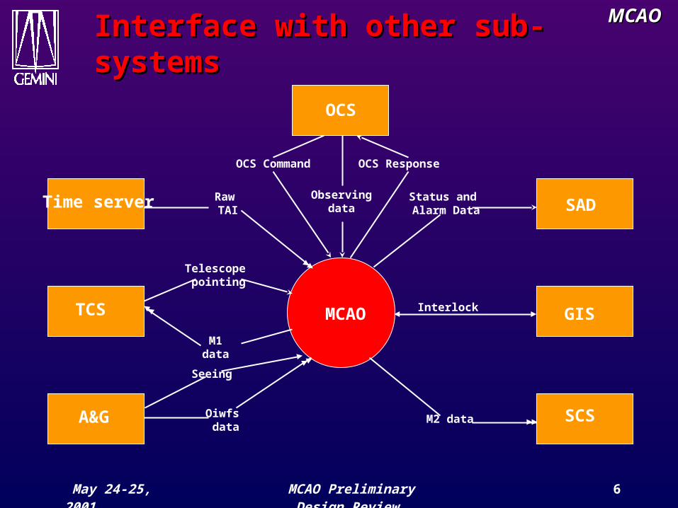
MCAOMCAOInterface with other sub-Interface with other sub-systemssystems
MCAO
SADStatus and Alarm Data
OCS
OCS ResponseOCS Command
Observingdata
GISInterlock
SCSM2 dataA&G Oiwfs data
Seeing
TCS
Telescope pointing
M1data
Time server Raw TAI
May 24-25, 2001 MCAO Preliminary Design Review
7
MCAOMCAO
Interface Control DocumentsInterface Control Documents
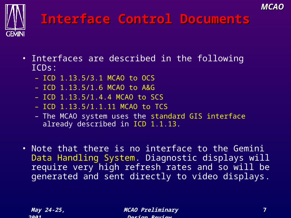
• Interfaces are described in the following ICDs:– ICD 1.13.5/3.1 MCAO to OCS– ICD 1.13.5/1.6 MCAO to A&G – ICD 1.13.5/1.4.4 MCAO to SCS – ICD 1.13.5/1.1.11 MCAO to TCS – The MCAO system uses the standard GIS interface
already described in ICD 1.1.13.
• Note that there is no interface to the Gemini Data Handling System. Diagnostic displays will require very high refresh rates and so will be generated and sent directly to video displays.

May 24-25, 2001 MCAO Preliminary Design Review
8
MCAOMCAO
MCAO controller architectureMCAO controller architecture
• The MCAO control system will be split in six independent sub-systems :
– The Real Time Controller,
– The AOM Component Controller ,
– The BTO / LLT Component Controller,
– The Laser Controller,
– The SALSA Controller,
– The Diagnostics Wavefront Sensor Controller.

May 24-25, 2001 MCAO Preliminary Design Review
9
MCAOMCAO
Gemini modelGemini model
• The MCAO control system will be implemented using the standard Gemini control system model.
• An Instrument Sequencer will manage the 6 independent subsystems and act as the main public interface for the entire MCAO system.
• The sequencer will coordinate all of the internal tasks and provide external systems with the commands and status information they need, to control the MCAO System.
May 24-25, 2001 MCAO Preliminary Design Review
10
MCAOMCAO
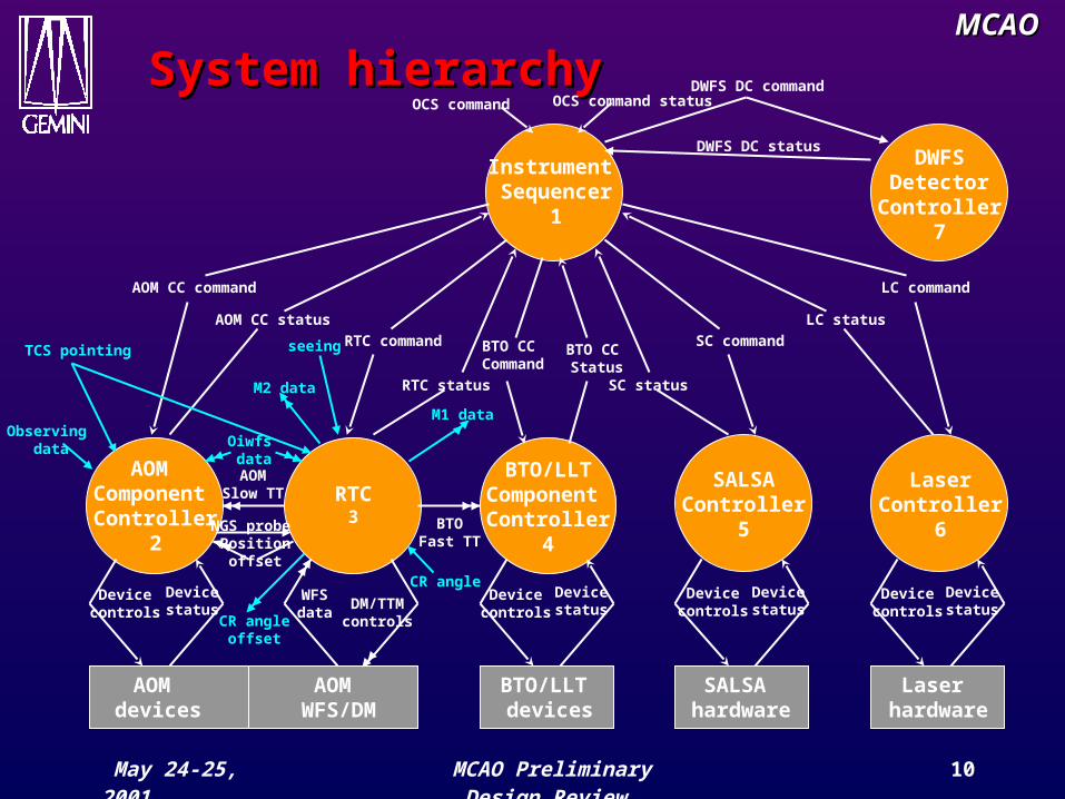
System hierarchySystem hierarchy
Instrument Sequencer
1
RTC3
AOM Component Controller
2
BTO/LLTComponent Controller
4
SALSAController
5
LaserController
6
Laser hardware
SALSA hardware
BTO/LLT devices
AOM devices
AOM WFS/DM
OCS command OCS command status
AOM CC command
AOM CC status
RTC command
RTC status
BTO CC Command
BTO CC Status
SC status
SC command
LC status
LC command
WFSdata
DM/TTMcontrols
Devicecontrols
Devicestatus
Devicecontrols
Devicecontrols
Devicecontrols
Devicestatus
Devicestatus
Devicestatus
TCS pointing
Oiwfs data
M2 data
M1 data
BTOFast TT
AOMSlow TT
NGS probe Position
offset
Observing data
seeing
CR angleoffset
CR angle
DWFS DC command
DWFS DC statusDWFS
DetectorController
7

May 24-25, 2001 MCAO Preliminary Design Review
11
MCAOMCAO
MCAO Sequencer - 1MCAO Sequencer - 1
• The Sequencer will be implemented using only standard EPICS records.
• Command and status information that pass between the OCS and MCAO systems is described in the OCS/MCAO ICD.
• The commands reboot, initialize, datum, park, test, simulate and debug will be implemented to perform global actions on all of the associated devices for all the sub-systems.
May 24-25, 2001 MCAO Preliminary Design Review
12
MCAOMCAO
MCAO Sequencer - 2MCAO Sequencer - 2
• The standard commands pause, continue, stop and abort will not be implemented. The observe command will be rejected during the preset directive and the others commands verify, endVerify, guide, endGuide, endObserve will be ignored.
• Night operation and calibration and maintenance sequences will be implemented using ocswish tool.
• The setup/engineering command set can be found in the MCAO Internal ICD.
May 24-25, 2001 MCAO Preliminary Design Review
13
MCAOMCAOBTO/LLT Component BTO/LLT Component ControllerController
• This sub-system is responsible for managing all of the opto-mechanical devices associated with the BTO and LLT under the direct control of the MCAO Instrument Sequencer.
• The commands initialize, datum, park, test, simulate and debug will be implemented to perform global actions on all of the associated devices.
• The component controller will be a hybrid EPICS/VxWorks implementation which uses a mix of standard EPICS records and custom assembly and device control records and also dedicated VxWorks tasks.

May 24-25, 2001 MCAO Preliminary Design Review
14
MCAOMCAO
BTO/LLT CC InterfacesBTO/LLT CC Interfaces
• The BTO/LLT CC will interface directly with:
– the RTC to receive Fast Steering Array commands,
– the SALSA sub-system to sense the state of the SALSA shutter,
– the Gemini GIS system to disable all motions in the case of a hardware interlock,
– the TCS system to read the telescope pointing information.

May 24-25, 2001 MCAO Preliminary Design Review
15
MCAOMCAO
BTO/LLT CC Design - 1BTO/LLT CC Design - 1
Device Hardware DesignLLT Cover AC motor with two limit
switches: 2 outputs and 2 inputs of a XVME244 digital I/O card.
2 EPICS binary output records and 2 EPICS binary input records.
Pointing mirror 2 DC servo motors: 2 channels of an OMS58 servo card.
2 EPICS device control records and a single EPICS assembly control record.
Centering mirror 2 DC servo motors: 2 channels of an OMS58 servo card.
2 EPICS device control records and a single EPICS assembly control record.
K mirror A DC servo motors: 1 channel of an OMS58 servo card.
A single EPICS device control record.
Top end ring mirror 2 DC servo motors: 2 channels of an OMS58 servo card.
2 EPICS device control records and a single EPICS assembly control record.

May 24-25, 2001 MCAO Preliminary Design Review
16
MCAOMCAO
BTO/LLT CC Design - 2BTO/LLT CC Design - 2
Device Hardware Design
Beam dump mirror AC motor with two limit switches: 2 outputs and 2 inputs of a XVME244 digital I/O card.
2 EPICS binary output records and 2 EPICS binary input records.
Corner cube shutter AC motor with two limit switches: 2 outputs and 2 inputs of a XVME244 digital I/O card.
2 EPICS binary output records and 2 EPICS binary input records.
Near-field chopper wheel
Single stepper motor with encoder: one axis of an OMS58 servo card.
A single EPICS device control record.
Centering array 10 DC servo motors: 10 channels of OMS58 servo cards.
10 EPICS device control records and 5 EPICS assembly control records
Pointing array 10 DC servo motors: 10 channels of OMS58 servo cards.
10 EPICS device control records and 5 EPICS assembly control records

May 24-25, 2001 MCAO Preliminary Design Review
17
MCAOMCAO
BTO/LLT CC Design - 3BTO/LLT CC Design - 3
Device Hardware DesignFast Steering Array Piezzo-electric actuators:
10 channels of XYCOM531 high-speed D/A card.
VxWorks task.
Quarter-wave plate Single stepper motor with encoder: one axis of an OMS58 servo card.
A single EPICS device control record.
Alignment camera selector
TTL selection signals: 3 output bit of an XVME244 digital I/O card.
3 EPICS binary output records.
Power meter A single analog input: one channel of the XYCOM 566 Analog I/O card.
A single EPICS analog input record.
Polarization sensor A single analog input: one channel of the XYCOM 566 Analog I/O card.
A single EPICS analog input record.
May 24-25, 2001 MCAO Preliminary Design Review
18
MCAOMCAO
BTO/LLT CC Design - 4BTO/LLT CC Design - 4
Device Hardware Design
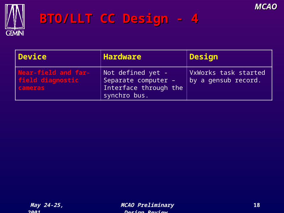
Near-field and far-field diagnostic cameras
Not defined yet - Separate computer – Interface through the synchro bus.
VxWorks task started by a gensub record.

May 24-25, 2001 MCAO Preliminary Design Review
19
MCAOMCAO
BTO/LLT CC Design – 5BTO/LLT CC Design – 5
• The BTO/LLT CC will be implemented using two separate CPU boards.
• The first CPU board will provide the EPICS interface and all device control. This board will also implement the following slow closed loop algorithms:– PM, KM, CM closed loop, – Beam diagnostic WFS and CA and PA closed loop,– Quarter wave plate closed loop.
• The second CPU board (non EPICS) will be dedicated to the fast TT mirror control at 800Hz.
• All of the closed loops will maintain circular buffers to hold debugging and display history data.

May 24-25, 2001 MCAO Preliminary Design Review
20
MCAOMCAOBTO/LLT CC hardware BTO/LLT CC hardware environmentenvironment
MV
ME
270
0 –
CP
U b
oard
OM
S58
mot
or c
ontr
olle
r
Control LAN
Time bus
To servo motor electronics
To TT mirrors
Ban
com
635
tim
e b
oard
MV
ME
270
0 –
CP
U b
oard
XY
CO
M53
1 D
A b
oard
VM
IVM
E55
88 R
M b
oard
Synchro bus
XY
CO
M 5
66 A
D b
oard
From sensors
OM
S58
mot
or c
ontr
olle
r
OM
S58
mot
or c
ontr
olle
r
OM
S58
mot
or c
ontr
olle
r
XY
CO
M 2
44 D
igit
al I
/O
BTO/LLT VME
BTO DWFS
To switches, relays, DC
motors
May 24-25, 2001 MCAO Preliminary Design Review
21
MCAOMCAO
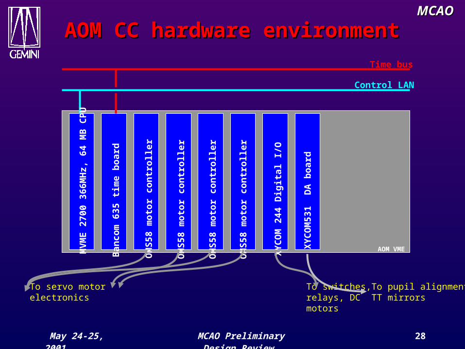
AOM Component ControllerAOM Component Controller
• This sub-system is responsible for managing all of the opto-mechanical devices (except the DM, TTM and the readout of the WFS) associated with the AOM under the direct control of the MCAO Instrument Sequencer.
• The commands initialize, datum, park, test, simulate and debug will be implemented to perform global actions on all of the associated devices.
• The component controller will be an all-EPICS implementation based on the Gemini Altair model which uses a mix of standard EPICS records and custom assembly and device control records.
• All of the closed loops will maintain circular buffers to hold debugging and display history data.

May 24-25, 2001 MCAO Preliminary Design Review
22
MCAOMCAO
AOM CC InterfacesAOM CC Interfaces
• The AOM CC will interface directly with:
– the RTC to receive LGS WFS pupil alignment data, to receive NGS probe position offsets and to send NGS probe positions,
– the SALSA sub-system to sense the state of the SALSA shutter,
– the Gemini GIS system to disable all motions in the case of a hardware interlock,
– the TCS system to read the telescope pointing information and to receive NGS probe position demands,
– the A&G to read OIWFS data,– The OCS to receive observing data.

May 24-25, 2001 MCAO Preliminary Design Review
23
MCAOMCAO
AOM CC Design - 1AOM CC Design - 1
Device Hardware DesignLGS simulated source array illumination
One output channel of a XVME244 output card.
A single EPICS binary output record.
LGS simulated source array position
A single DC motor with 2 limit switches: 2 outputs and 2 inputs of a XVME244 digital I/O card.
2 EPICS binary output records and 2 EPICS binary input records.
LGS simulated source array focus
A single DC servo motor: one axis of an OMS58 servo card.
A single EPICS device control.
NGS peripheral simulated source array illumination
One output channel of a XVME244 output card.
A single EPICS binary output record.
NGS central simulated source array illumination
One output channel of a XVME244 output card.
A single EPICS binary output record.
May 24-25, 2001 MCAO Preliminary Design Review
24
MCAOMCAO
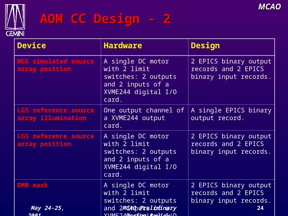
AOM CC Design - 2AOM CC Design - 2
Device Hardware Design
NGS simulated source array position
A single DC motor with 2 limit switches: 2 outputs and 2 inputs of a XVME244 digital I/O card.
2 EPICS binary output records and 2 EPICS binary input records.
LGS reference source array illumination
One output channel of a XVME244 output card.
A single EPICS binary output record.
LGS reference source array position
A single DC motor with 2 limit switches: 2 outputs and 2 inputs of a XVME244 digital I/O card.
2 EPICS binary output records and 2 EPICS binary input records.
DM0 mask A single DC motor with 2 limit switches: 2 outputs and 2 inputs of a XVME244 digital I/O card.
2 EPICS binary output records and 2 EPICS binary input records.
May 24-25, 2001 MCAO Preliminary Design Review
25
MCAOMCAO
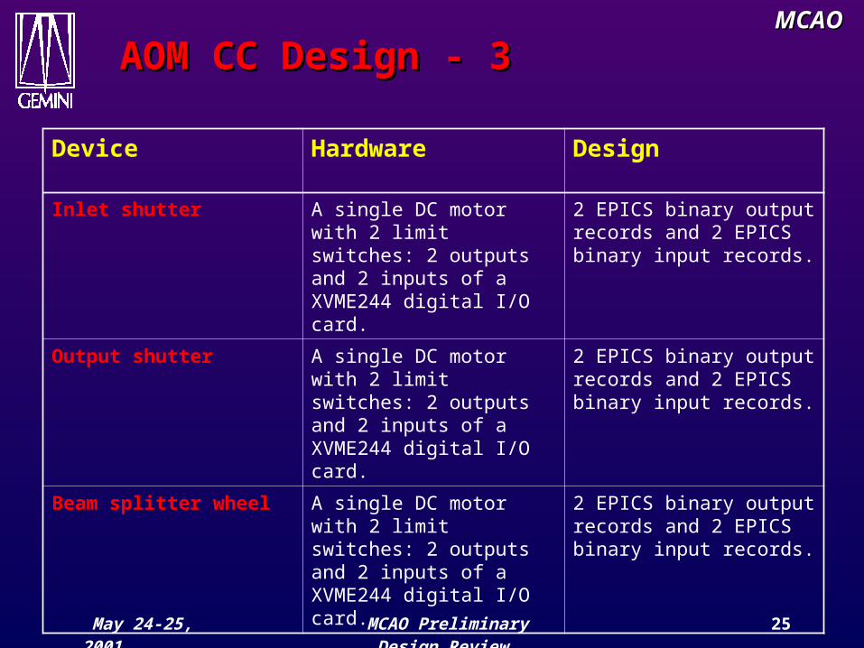
AOM CC Design - 3AOM CC Design - 3
Device Hardware Design
Inlet shutter A single DC motor with 2 limit switches: 2 outputs and 2 inputs of a XVME244 digital I/O card.
2 EPICS binary output records and 2 EPICS binary input records.
Output shutter A single DC motor with 2 limit switches: 2 outputs and 2 inputs of a XVME244 digital I/O card.
2 EPICS binary output records and 2 EPICS binary input records.
Beam splitter wheel A single DC motor with 2 limit switches: 2 outputs and 2 inputs of a XVME244 digital I/O card.
2 EPICS binary output records and 2 EPICS binary input records.
May 24-25, 2001 MCAO Preliminary Design Review
26
MCAOMCAO
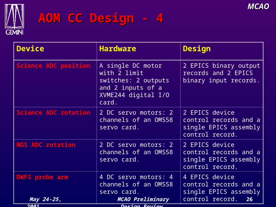
AOM CC Design - 4AOM CC Design - 4
Device Hardware DesignScience ADC position A single DC motor with 2
limit switches: 2 outputs and 2 inputs of a XVME244 digital I/O card.
2 EPICS binary output records and 2 EPICS binary input records.
Science ADC rotation 2 DC servo motors: 2 channels of an OMS58 servo card.
2 EPICS device control records and a single EPICS assembly control record.
NGS ADC rotation 2 DC servo motors: 2 channels of an OMS58 servo card.
2 EPICS device control records and a single EPICS assembly control record.
DWFS probe arm 4 DC servo motors: 4 channels of an OMS58 servo card.
4 EPICS device control records and a single EPICS assembly control record.
May 24-25, 2001 MCAO Preliminary Design Review
27
MCAOMCAO
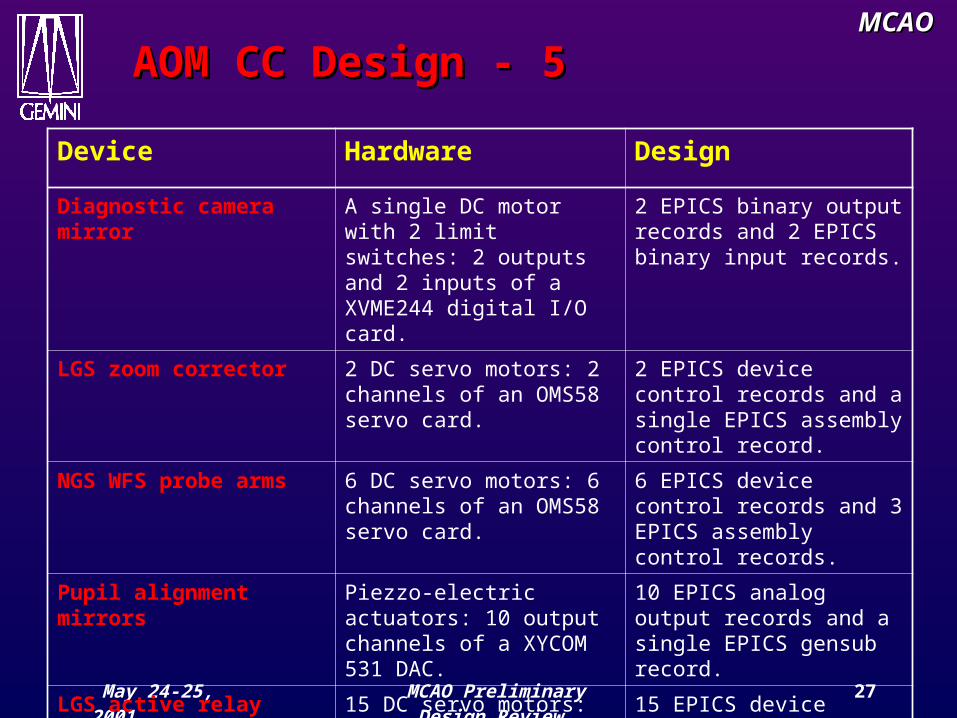
AOM CC Design - 5AOM CC Design - 5
Device Hardware DesignDiagnostic camera mirror
A single DC motor with 2 limit switches: 2 outputs and 2 inputs of a XVME244 digital I/O card.
2 EPICS binary output records and 2 EPICS binary input records.
LGS zoom corrector 2 DC servo motors: 2 channels of an OMS58 servo card.
2 EPICS device control records and a single EPICS assembly control record.
NGS WFS probe arms 6 DC servo motors: 6 channels of an OMS58 servo card.
6 EPICS device control records and 3 EPICS assembly control records.
Pupil alignment mirrors
Piezzo-electric actuators: 10 output channels of a XYCOM 531 DAC.
10 EPICS analog output records and a single EPICS gensub record.
LGS active relay elements
15 DC servo motors: 15 channels of an OMS58 servo card.
15 EPICS device control records and 5 EPICS assembly control records.
May 24-25, 2001 MCAO Preliminary Design Review
28
MCAOMCAOAOM CC hardware AOM CC hardware environmentenvironment
MV
ME
270
0 36
6MH
z, 6
4 M
B C
PU
Ban
com
635
tim
e b
oard
OM
S58
mot
or c
ontr
olle
r
OM
S58
mot
or c
ontr
olle
r
OM
S58
mot
or c
ontr
olle
r
XY
CO
M 2
44 D
igit
al I
/O
Control LAN
Time bus
To servo motor electronics
To switches, relays, DC motors
To pupil alignmentTT mirrors
XY
CO
M53
1 D
A b
oard
OM
S58
mot
or c
ontr
olle
rAOM VME

May 24-25, 2001 MCAO Preliminary Design Review
29
MCAOMCAO
SALSA ControllerSALSA Controller
• Presented with the SALSA sub-system later in the morning
May 24-25, 2001 MCAO Preliminary Design Review
30
MCAOMCAO
DWFS Controller RequirementsDWFS Controller Requirements
• The Diagnostic Wavefront sensor is 32x32 sub-aperture SH WFS, each sub aperture being composed of at least 16x16 pixels. A 1024x1024 standard CCD will be used.
• This diagnostic WFS will only be used during the day to calibrate the DM commands to insure the science path wavefront quality.
• Basic signal processing will be required at a slow rate:– read the pixel image, save to a file,– subtract a dark to a pixel image,– compute the centroids and save the centroids to a file.

May 24-25, 2001 MCAO Preliminary Design Review
31
MCAOMCAO
DWFS Controller DesignDWFS Controller Design
• A frame grabber installed on a PC system or on a Unix host will be implemented to read the pixel data.
• Two solutions to perform signal processing:– Use of WaveLab,– in house developed IDL routines.
• In the two cases, it will be very easy for the instrument sequencer to interface these tools.
• Interface with MCAO sequencer has been defined and is described in the ICDs.
May 24-25, 2001 MCAO Preliminary Design Review
32
MCAOMCAO
Real Time ControllerReal Time Controller
• This controller is dedicated to the AO control loop itself. It is the heart of the system and the most critical in terms of real time performances
• It will handle 3 basic real time functions:– The NGS real time control loop,– The LGS real time control loop,– The optimization and background processes.

May 24-25, 2001 MCAO Preliminary Design Review
33
MCAOMCAO
LGS WFS pixels (7)
LGS WFS slopes
computation (8)
Extrapolate un-illuminatined DM
actuators (11)
DM actuator controls
++
+
(10)
DMs filter+
Reference slopes
LGS DM actuator controls
computation(9)
RTC block diagramRTC block diagram
NGS WFS Slopes computation (1)
NGS WFS Pixels (0)
TTM actuator controls
computation (2)
NGS DM mode computation
(4)
TTM filter (3)
TTM actuator controls
OIWFS TTConversion to DMs
actuators(6)
NGS DM filter(5)
OIWFS Focus
Adjust LGS WFS focus lens and active
relay elements
Offload M2 via synchro bus
(16)
TT F
PSF, r0 (15)
LGS and NGS slopes, DM and TTM actuator
controls CR angle
NGS modal Optimization
(14)
Adjust NGS WFS position and Cass
Rotator (13)
NGS WFS Gain optimization
(12)
Lookup table (seeing)
Field distorsion
OIWFS TT
Observation parameters
ProbePositions
Offload M1via EPICS
Records (22)
Null DMPiston,waffle,
Tilt (19)
Loop gain and control matrix
optimization (18)
Telescope pointing
Adjust BTO TT (20)
Real Time display (23)
LGS WFS Gain optimization
(17)
A
A
Fie
ld r
otat
ion
Ref
eren
ce s
lop
es
Adjust the AOM TT
(21)
B
B
CR angle
May 24-25, 2001 MCAO Preliminary Design Review
34
MCAOMCAO
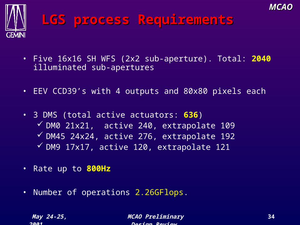
LGS process RequirementsLGS process Requirements
• Five 16x16 SH WFS (2x2 sub-aperture). Total: 2040 illuminated sub-apertures
• EEV CCD39’s with 4 outputs and 80x80 pixels each
• 3 DMS (total active actuators: 636) DM0 21x21, active 240, extrapolate 109 DM45 24x24, active 276, extrapolate 192 DM9 17x17, active 120, extrapolate 121
• Rate up to 800Hz
• Number of operations 2.26GFlops.

May 24-25, 2001 MCAO Preliminary Design Review
35
MCAOMCAO
NGS process requirementsNGS process requirements
• 3 tip/tilt sensors using APDs
• 1 TTM
• 3 DM modes
• Rate up to 800Hz
• Operation number: 3.16 MFlops

May 24-25, 2001 MCAO Preliminary Design Review
36
MCAOMCAO
RTC synchronisationRTC synchronisationLGS WFS exposure
time - 1.25ms
LGS WFS readout time (10) – 1ms
LGS DM computation
(11), (12)
NGS TTM computation(1), (2), (3)
NGS DM computation (4)
NGS WFS exposure time - 1.25ms
NGS WFS readout time (0)
Final DM computation
(13), (14), (15)
TTM commands
DMcommands
TTM commands
DMcommands
DMcommands
TTM commands
DM0DM45DM9
DM0DM45DM9

May 24-25, 2001 MCAO Preliminary Design Review
37
MCAOMCAOComputation requirement Computation requirement summarysummary
RTC Process Frequency Computation requirement
NGS process 800Hz 3.16MFlops
LGS process 800Hz 2.26GFlops
• Computation requirement also estimated for all optimization and background processes.

May 24-25, 2001 MCAO Preliminary Design Review
38
MCAOMCAO
RTC architectureRTC architecture
• Since the CoDR, 2 actions:– a VSS4 Synergy Micro Systems board a VME64
back plane has been purchased: VME DSP-Quad PPC 7400@433Mhz, 256 Mb, 8Mb Backside Cache (2:1 ratio), VME64x. Benchmarks are right now performed by HIA to assess the suitability of this board.
– contract some vendors to study other architectures for our requirements. Two vendors have been selectioned :
• The Optical Science Company (tOSC), located in Anaheim-California,
• SHAKTIWARE, located in Marseille France.

May 24-25, 2001 MCAO Preliminary Design Review
39
MCAOMCAO
One possible RTC approachOne possible RTC approach
VM
IVM
E55
88 R
efle
ctiv
e m
emor
y b
oard
Ban
com
635
tim
e b
oard
DM9
TTM
VSS4 VME Board
DM45DM0
EPICS
CCD Controller
LGS CB image
LGS CB slopes
CB actuator DM0
CB actuator DM45
CB actuator DM9
CB actuator TTM
NGS CB modes
NGS CB slopes
SDSU
PM
C I
FP
IO P
MC
boa
rdP
IO P
MC
boa
rd
PIO
PM
C b
oard
PIO
PM
C b
oard
PIO
PM
C b
oard
PIO
PM
C b
oard
APD
DA
C P
MC
boa
rdA
PD
PM
C I
F
boar
d
Vid
eo b
oard
XY
CO
M24
4 D
igit
al I
/O b
oard
VSS4 VME Board
VSS4 VME Board
VSS4 VME Board
LGSoptim
DM0
DM0
DM0 DM45
DM45
DM45
DM45
DM9 DM9
Video PSF/r0
Modaloptim
NGSoptim
TTM
May 24-25, 2001 MCAO Preliminary Design Review
40
MCAOMCAO
RTC software designRTC software design
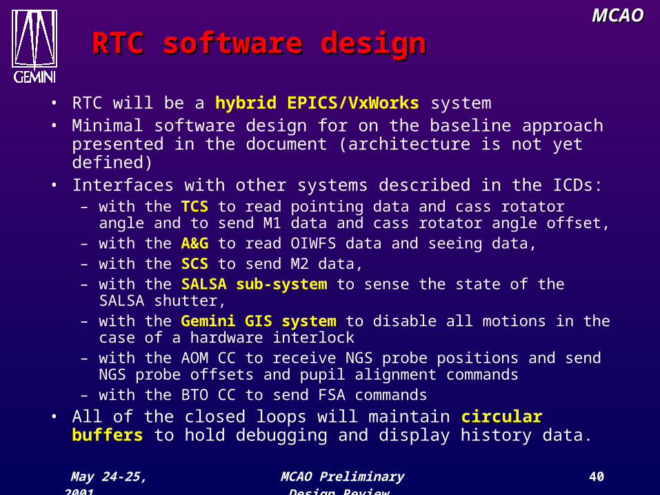
• RTC will be a hybrid EPICS/VxWorks system• Minimal software design for on the baseline approach
presented in the document (architecture is not yet defined)• Interfaces with other systems described in the ICDs:
– with the TCS to read pointing data and cass rotator angle and to send M1 data and cass rotator angle offset,
– with the A&G to read OIWFS data and seeing data,– with the SCS to send M2 data,– with the SALSA sub-system to sense the state of the SALSA
shutter,– with the Gemini GIS system to disable all motions in the
case of a hardware interlock– with the AOM CC to receive NGS probe positions and send NGS
probe offsets and pupil alignment commands– with the BTO CC to send FSA commands
• All of the closed loops will maintain circular buffers to hold debugging and display history data.

May 24-25, 2001 MCAO Preliminary Design Review
41
MCAOMCAO
PDR AgendaPDR Agenda
Friday, 5/250800 Laser System 0900 CTIO Sodium Studies0915 Control System0945 Break1000 RTC Electronics1045 Safety System1100 Availability analysis1130 Closed vendor
Sessions1200 Lunch
1300 Cost and schedule1400 Committee session1700 Committee report1800 Adjourn
May 24-25, 2001 MCAO Preliminary Design Review
42
MCAOMCAO
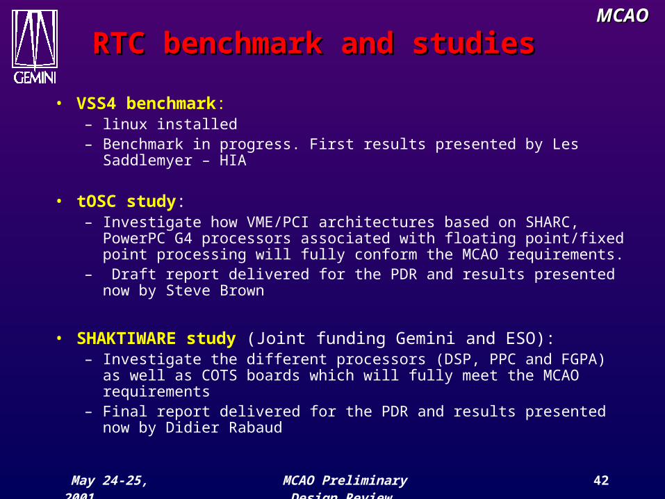
RTC benchmark and studiesRTC benchmark and studies
• VSS4 benchmark: – linux installed– Benchmark in progress. First results presented by Les
Saddlemyer – HIA
• tOSC study: – Investigate how VME/PCI architectures based on SHARC,
PowerPC G4 processors associated with floating point/fixed point processing will fully conform the MCAO requirements.
– Draft report delivered for the PDR and results presented now by Steve Brown
• SHAKTIWARE study (Joint funding Gemini and ESO):– Investigate the different processors (DSP, PPC and FGPA) as
well as COTS boards which will fully meet the MCAO requirements
– Final report delivered for the PDR and results presented now by Didier Rabaud