
MC88(i)Terminal Users Guide
22
MC 88(i)T User Guide MC88(i)Term_UG_en_141112.doc Page 1 of 22 MC88(i)Terminal Users Guide Title: MC88(i)T User Guide Version: 0.0.0.2 Status: Preliminary Date: November 14, 2012 Doc: MC88(i)T_UG_EN_Rel. 0.2 Author: Wacker Copyright: MC Technologies GmbH, Hannover / Germany
Transcript of MC88(i)Terminal Users Guide

MC 88(i)T User Guide
MC88(i)Term_UG_en_141112.doc Page 1 of 22
MC88(i)Terminal Users Guide
Title: MC88(i)T User Guide Version: 0.0.0.2 Status: Preliminary Date: November 14, 2012 Doc: MC88(i)T_UG_EN_Rel. 0.2 Author: Wacker Copyright: MC Technologies GmbH, Hannover / Germany

MC 88(i)T User Guide
MC88(i)Term_UG_en_141112.doc Page 2 of 22
1.1 Contents 1.1 Contents ......................................................................................................................................... 2 1.2 Figures ........................................................................................................................................... 3 1.3 Tables ............................................................................................................................................ 3 1.4 Revision history .............................................................................................................................. 3 1.5 Legal information ........................................................................................................................... 3
1.5.1 Definitions ................................................................................................................................ 3 1.5.2 Disclaimers .............................................................................................................................. 4
1.6 Terms and abbreviations ............................................................................................................... 4 1.7 Related documents ........................................................................................................................ 5
2 Introduction ........................................................................................................................................... 6 2.1 Features ......................................................................................................................................... 6 2.2 Differences between the MC88T and MC88iT ............................................................................ 66
3 Safety requirement ............................................................................................................................... 8 4 Product description ............................................................................................................................... 9 5 Interface description ............................................................................................................................. 9
5.1 Overview ........................................................................................................................................ 9 5.2 Supported operating modes ........................................................................................................ 10 5.3 Power supply and on/off control .................................................................................................. 10 5.4 Turn on ......................................................................................................................................... 11 5.5 Turn off ......................................................................................................................................... 11
5.5.1 Normal shutdown .................................................................................................................. 11 5.5.2 Emergency shutdown ............................................................................................................ 11
5.5.2.1 Disconnecting the power supply ..................................................................................... 11 5.5.2.2 Automatic thermal shutdown .......................................................................................... 12
5.6 Serial interfaces ........................................................................................................................... 12 5.6.1 EIA/RS-232 interface ............................................................................................................ 12
5.6.1.1 DTR - Data terminal ready .............................................................................................. 12 5.6.1.2 RI – Ring indication ........................................................................................................ 12
5.6.2 USB interface (Mini-USB Connectro, Type B) (MC88iT only) .............................................. 12 5.6.2.1 Suspension of the USB interface ................................................................................... 12
5.7 SIM interface ................................................................................................................................ 13 5.8 Radio interface ............................................................................................................................. 14 5.9 Staus LEDs .................................................................................................................................. 14
5.9.1 Red LED ........................................................................... Fehler! Textmarke nicht definiert. 5.9.2 Yellow LED ............................................................................................................................ 15 5.9.3 Blue LED (MC88iT only) ....................................................................................................... 15
6 AT commands .................................................................................................................................... 16 7 Software-/Firmware-update ................................................................................................................ 16 8 Mechanical characteristics and mounting advice ............................................................................... 16
8.1 Mounting example ........................................................................................................................ 17 9 Electrical and environmental characteristics ...................................................................................... 18
9.1 Absolute maximum ratings .......................................................................................................... 18 9.2 Operation supply specification ................................................ Fehler! Textmarke nicht definiert. 9.3 On-board operating temperature of build in GSM engine ............................................................ 19 9.4 On/off control line specification .................................................................................................... 19 9.5 EIA/RS-232 interface specification .............................................................................................. 19 9.6 USB interface specification .......................................................................................................... 19
10 Power supplies ................................................................................................................................. 20 11 Over temperature ............................................................................................................................. 20 12 Regulatory and type approval information ........................................................................................ 20
12.1 Directives and standards ........................................................................................................... 20 12.2 SAR requirements specific to portable mobiles ......................................................................... 20
13 Special features for Java applications .............................................................................................. 21 13.1 Configuration the special functions with "Ccfg.exe" .................................................................. 21 13.2 Watchdog ................................................................................................................................... 21 13.3 Auto-Start ................................................................................................................................... 22
14 Programming GPIOs in (Java) applications ..................................................................................... 22 15 Programming hints and warnings ..................................................................................................... 22

MC 88(i)T User Guide
MC88(i)Term_UG_en_141112.doc Page 3 of 22
1.2 Figures Figure 1: System overview ...................................................................................................................... 9 Figure 2: Pin assignment of the 6-pole Western jack for power supply, ignition and power down ....... 11 Figure 3: EIA/RS-232 interface (D-Sub 9-pole female connector) ........................................................ 12 Figure 4: USB interface (Mini-USB Connector, Type B) (MC88iT only) ............................................... 10 Figure 5: SIM interface .......................................................................................................................... 13 Figure 6: Radio interface ....................................................................................................................... 14 Figure 7: recommended antenna connector ......................................................................................... 14 Figure 8: Status LEDs ........................................................................................................................... 14 Figure 9: Design drawing ....................................................................................................................... 17 Figure 10: Recommend screws ............................................................................................................. 17 Figure 11: "Ccfg.exe" ............................................................................................................................. 21
1.3 Tables Table 1: Revision history ......................................................................................................................... 3 Table 2: Terms and abbreviations ........................................................................................................... 5 Table 3: Features .................................................................................................................................... 7 Table 4: Differences between the MC88T and MC88iT .......................................................................... 7 Table 5: Supported operating modes .................................................................................................... 10 Table 6: Pin assignment of the 6-pole Western jack for power supply, ignition and power down ........ 11 Table 7: Pin assignment of the EIA/RS-232 plug .................................................................................. 12 Table 8 Coding of the red LED ......................................................... Fehler! Textmarke nicht definiert. Table 9: Coding of the yellow LED ........................................................................................................ 15 Table 10: Mechanical and operating characteristics ............................................................................. 16 Table 11: Absolute maximum ratings .................................................................................................... 18 Table 12: Operation supply specification .............................................................................................. 18 Table 13: Average supply current ......................................................................................................... 19 Table 14: On-board operating temperature of build in GSM engine ..................................................... 19 Table 15: On/off control line specification ............................................................................................. 19 Table 16: EIA/RS-232 interface specification ........................................................................................ 19 Table 17: GPIO-pin configuration .......................................................................................................... 22 Table 18: GPIO output setting ............................................................................................................... 22
1.4 Revision history Revision Date Status Description Original 2010-06-12 Advace Information/Confidential Firs release 0.0.0.2 2010-06-14 Preliminary
Table 1: Revision history
1.5 Legal information
1.5.1 Definitions Advance Information
The document contains the design specification for product development. Specifications may change in any manner without notice.
Draft The document contains specifications that are still under internal review and subject to formal approval, which may result in modifications or additions. The publisher/manufacturer reserves the right to make changes at any time without notice to improve the design.
Preliminary The document contains preliminary data; supplementary data will be published at a later date. The publisher/manufacturer reserves the right to make changes at any time without notice to improve the design.
No Identification Needed
The document contains the final specifications. The publisher/manufacturer reserves the right to make changes at any time without notice to improve the design.
Obsolete The document contains specifications on a product that has been discontinued. The document is printed for reference information only.

MC 88(i)T User Guide
MC88(i)Term_UG_en_141112.doc Page 4 of 22
1.5.2 Disclaimers General Information in this document is believed to be accurate and reliable and shall not be considered as a guarantee of characteristics or the suitability of the products for any particular purpose, nor does the publisher / manufacturer assume any liability arising out of the application or use of any product or circuit, and specifically disclaims any and all liability, including without limitation special, consequential or incidental damages. However, the publisher / manufacturer does not give any representations or warranties, expressed or implied, as to the accuracy or completeness of such information and shall have no liability for the consequences of use of such information. "Typical" parameters which may be provided in the documents and/or specifications can and do vary in different applications and actual performance may vary over time. All operating parameters, including "Typical" must be validated for each customer application by customer’s technical experts. For additional information, please contact your local Sales Representative. Right to make changes The publisher / manufacturer reserves the right to make corrections, modifications, enhancements, improvements, and other changes to its products and services at any time and to discontinue any product or service without notice. Customers should obtain the latest relevant information before placing orders and should verify that such information is current and complete. This document supersedes and replaces all information supplied prior to the publication hereof. Suitability for use The publisher / manufacturer products are not designed, authorized or warranted to be suitable for use in medical, military, aircraft, space or life support equipment, nor in applications where failure or malfunction of a product can reasonably be expected to result in personal injury, death or severe property or environmental damage. The publisher / manufacturer accept no liability for inclusion and/or use of products in such equipment or applications and therefore such inclusion and/or use are at the customer’s own risk. Applications Applications that are described herein for any of these products are for illustrative purposes only. The publisher / manufacturer make no representation or warranty that such applications will be suitable for the specified use without further testing or modification. Trademarks All referenced brands, product names, service names and trademarks are the property of their respective owners. Copyright All rights reserved. Reproduction in whole or in part is prohibited without the prior written consent of the copyright owner. © Copyright by MC Technologies GmbH, Hannover / Germany The copyright owner of some figures, tables and descriptions are the Cinterion Wireless Modules GmbH, Munich / Germany.
1.6 Terms and abbreviations Abbreviation Description ASC Asynchronous Controller. Abbreviations used for first and second serial interface. CSD Circuit Switched Data CTS Clear To Send DCD Data Carrier Detect DCE Data Communication Equipment (typically a modem or a terminal) DSR Data Set Ready DTE Data Terminal Equipment (typically a computer, notebook or a GSM application) DTR Data Terminal Ready EIA Electronic Industries Alliance FME Sub-miniature connector for radio frequencies IDE Integrated Development Environment J2ME Java 2 Platform, Micro Edition Java METM Java Mobile Edition

MC 88(i)T User Guide
MC88(i)Term_UG_en_141112.doc Page 5 of 22
Abbreviation Description GND Ground GPIO General Purpose Input / Output GPRS General Packet Radio Service GSM Global Standard for Mobile Communications I²C Inter-integrated Circuit IP Internet Protocol I/O Input / Output JDK Java Development Kit LED Light Emitting Diode ME Mobile Equipment MO Mobile Originated MS Mobile Station MT Mobile Terminated NDIS Network Driver Interface Specification PBCCH Packet Broadcast Control Channel PDP Packet Data Protocol PIN Personal Identification Number PPP Point-to-Point Protocol RAM Random Access Memory RF Radio Frequency RIL Radio Interface Layer RLP Radio Link Protocol RO Ring Indicator RSA Remote SIM Access RTS Ready To Send RXD Receive Data SIM Subscriber Identification Module SPI Serial Peripheral Interface SMS Short Message Service tbd To be defined TCP Transmission Control Protocol TXD Transmit Data UART Universal asynchronous receiver-transmitter URC Unsolicited Result Codes USSD Unstructured Supplementary Service Data
Table 2: Terms and abbreviations
1.7 Related documents [1] EGS5 Hardware Interface Description, Cinterion Wireless Modules GmbH [2] EGS5 AT Command Set, Cinterion Wireless Modules GmbH [3] Java User's Guide, Cinterion Wireless Modules GmbH

MC 88(i)T User Guide
MC88(i)Term_UG_en_141112.doc Page 6 of 22
2 Introduction The MC88(i)T is a Java TM-based GSM/GPRS-terminal for control, measurement, security, vending systems and mobile communications. The MC88(i)T supports the Java J2METM profile IMP 2.0 (downward-compatible with IMP 1.0) and quadband technology (850/900/1800/1900 MHz) for GSM networks. The complete software development platform is free of charge. The Java METM is provided by SUN Microsystems, http://java.sun.com/javame/ A Java IDE is provided by the Eclipse Foundation, http://www.eclipse.org The installation and use is decrypting in [3] Java User's Guide. The control of the MC88(i)T operates with AT Commands1 via the serial interface (EIA/RS-232), via the USB interface (MC88iT only) or inside a Java application as explained in [3] Java User's Guide. All AT Commands are summarized in [2] EGS5 AT Command Set. Additional hardware information are descript in [1] EGS5 Hardware Interface Description.
2.1 Features The GSM- and GPRS-features are provided by the integrated GSM-/GPRS-engine EGS5. Most of them are supported with the MC88(i)T: Feature Implementation General Frequency bands
Quad band: GSM 850/900/1800/1900 MHz
GSM class Small MS Output power (according to Release 99, V5)
• Class 4 (+33dBm ±2dB) for EGSM850 • Class 4 (+33dBm ±2dB) for EGSM900 • Class 1 (+30dBm ±2dB) for GSM1800 • Class 1 (+30dBm ±2dB) for GSM1900
The values stated above are maximum limits. According to Release 99, the maximum output power in a multi slot configuration may be lower. The nominal reduction of maximum output power varies with the number of uplink timeslots used and amounts to 3.0dB for 2Tx, 4.8dB for 3Tx and 6.0dB for 4Tx.
Ambient operating temperature according to IEC 60068-2
• Normal operation: -30°C to +75°C • Restricted operation: +75°C to +85°C; -30°C to -40°C
GSM / GPRS features Data transfer GPRS:
• Multi slot Class 12 • Full PBCCH support • Mobile Station Class B • Coding Scheme 1 – 4
CSD: • V.110, RLP, non-transparent • 2.4, 4.8, 9.6, 14.4kbps • USSD
PPP-stack for GPRS data transfer SMS Point-to-point MT and MO
Cell broadcast Text and PDU mode Storage: SIM card plus 25 SMS locations in mobile equipment Transmission of SMS alternatively over CSD or GPRS. Preferred mode can be user defined.
Fax Group 3; Class 1
1 AT Commands based on the Hayes command set developed in the 1970th; a command-language for modem.

MC 88(i)T User Guide
MC88(i)Term_UG_en_141112.doc Page 7 of 22
Feature Implementation AT commands
AT-Hayes GSM 07.05 and 07.07, Cinterion AT commands for RIL compatibility (NDIS/RIL)
Java platform
Java Virtual Machine with APIs for AT Parser, Serial Interface, Flash File-System and TCP/IP Stack. Major benefits: seamless integration into Java applications, ease of programming, no need for application microcontroller, extremely cost-efficient hardware and software design – ideal platform for industrial GSM applications. The memory space available for Java programs is around 1.7 MB in the flash file system and around 400k RAM. Application code and data share the space in the flash file system and in RAM.
SIM Application Toolkit
SAT Release 99
TCP/IP stack Access by AT commands Remote SIM Access
EGS5 supports Remote SIM Access. RSA enables EGS5 to use a remote SIM card via its serial interface and an external application, in addition to the SIM card locally attached to the dedicated lines of the application interface. The connection between the external application and the remote SIM card can be a Bluetooth wireless link or a serial link. The necessary protocols and procedures are implemented according to the “SIM Access Profile Interoperability Specification of the Bluetooth Special Interest Group”.
Firmware update
Generic update from host application over ASC0.
Interface 1 serial interfaces
ASC0: • 8-wire modem interface with status and control lines, unbalanced,
asynchronous • Fixed bit rates: 300 bps to 921,600 bps • Autobauding: 1,200 bps to 460,800 bps • RTS0/CTS0 and XON/XOFF flow control. • Multiplex ability according to GSM 07.10 Multiplexer Protocol.
USB Supports a USB 2.o Full Speed (12Mbit/s) slave interface (only MC88iT) I²C I²C bus for 7-bit addressing and transmission rates up to 400kbps. Programmable
with AT command. (only used inside the terminal)
SIM interface Supported SIM cards: 3V, 1.8V Antenna 50Ohms. External antenna can be connected via antenna connector. Power on/off, Reset Power on/off Switch-on by hardware pin IGT
Switch-off by AT command (AT^SMSO) Automatic switch-off in case of critical temperature and voltage conditions.
Reset Orderly shutdown and reset by AT command Emergency reset by hardware pin EMERG_RST and IGT.
Special features Real time clock
Timer functions via AT commands
GPIO 10 I/O pins of the application interface programmable as GPIO. Programming is done via AT commands. Alternatively, GPIO pin10 is configurable as pulse counter. (only used inside the terminal)
Phonebook SIM and phone Table 3: Features

MC 88(i)T User Guide
MC88(i)Term_UG_en_141112.doc Page 8 of 22
2.2 Differences between the MC88T and MC88iT The MC88T and MC88iT differ ony in the UsB connection of the MC88iT (see 5.6.2 USB interface (Mini-USB Connector, Type B)(MC88iT only), page 12) Terminal USB interface Recommendations MC88T Without Recommend for applications with EIA-232 interface MC88iT Mini-USB Recommend for application without EIA-232 interface but with USB
interface (host, e.g. Personal Computer) Table 4: Features
3 Safety requirement
When in a hospital or other health care facility, observe the restrictions on the use of mobiles. Switch the cellular terminal or mobile off, if instructed to do so by the guidelines posted in sensitive areas. Medical equipment may be sensitive to RF energy. The operation of cardiac pacemakers, other implanted medical equipment and hearing aids can be affected by interference from cellular terminals or mobiles placed close to the device. If in doubt about potential danger, contact the physician or the manufacturer of the device to verify that the equipment is properly shielded. Pacemaker patients are advised to keep their hand-held mobile away from the pacemaker, while it is on.
Switch off the cellular terminal or mobile before boarding an aircraft. Make sure it cannot be switched on inadvertently. The operation of wireless appliances in an aircraft is forbidden to prevent interference with communications systems. Failure to observe these instructions may lead to the suspension or denial of cellular services to the offender, legal action, or both.
Do not operate the cellular terminal or mobile in the presence of flammable gases or fumes. Switch off the cellular terminal when you are near petrol stations, fuel depots, chemical plants or where blasting operations are in progress. Operation of any electrical equipment in potentially explosive atmospheres can constitute a safety hazard.
Your cellular terminal or mobile receives and transmits radio frequency energy while switched on. Remember that interference can occur if it is used close to TV sets, radios, computers or inadequately shielded equipment. Follow any special regulations and always switch off the cellular terminal or mobile wherever forbidden, or when you suspect that it may cause interference or danger.
Road safety comes first! Do not use a hand-held cellular terminal or mobile when driving a vehicle, unless it is securely mounted in a holder for speakerphone operation. Before making a call with a hand-held terminal or mobile, park the vehicle. Speakerphones must be installed by qualified personnel. Faulty installation or operation can constitute a safety hazard.
IMPORTANT! Cellular terminals or mobiles operate using radio signals and cellular networks. Because of this, connection cannot be guaranteed at all times under all conditions. Therefore, you should never rely solely upon any wireless device for essential communications, for example emergency calls. Remember, in order to make or receive calls, the cellular terminal or mobile must be switched on and in a service area with adequate cellular signal strength. Some networks do not allow for emergency calls if certain network services or phone features are in use (e.g. lock functions, fixed dialing etc.). You may need to deactivate those features before you can make an emergency call. Some networks require that a valid SIM card be properly inserted in the cellular terminal or mobile.
Bear in mind that exposure to excessive levels of noise can cause physical damage to users! With regard to acoustic shock, the cellular application must be designed to avoid unintentional increase of amplification, e.g. for a highly sensitive earpiece. A protection circuit should be implemented in the cellular application.
If a power supply unit is used to supply the device it must meet the demands placed on SELV circuits in accordance with EN60950. The maximum permissible connection length between the device and the supply source should not exceed 3m.

MC 88(i)T User Guide
MC88(i)Term_UG_en_141112.doc Page 9 of 22
According to the guidelines for human exposure to radio frequency energy, an antenna connected to the SMA jack of the device should be placed at least 20cm away from human bodies.
4 Product description The core of the MC88(i)T is a Cinterion engine EGS5 and a microcontroller.
Figure 1: System overview
The micro controller is responsible for the power supply, the interfaces and supervised the operation of the GSM engine EGS5. Detailed descriptions of the GSM engine EGS5 are [1] EGS5 Hardware Interface Description and [2] EGS5 AT Command Set. Please consider these documents.
5 Interface description
5.1 Overview The MC88(i)T provide the following connectors:
6-pole Western plug (female) for power supply, ignition and power down signal (Emergency off) FME jack (male) for antenna (Radio Interface) SIM card holder 9-pole Sub-D plug (female) for EIA/RS-232 (RS-232) serial interface Optional a Mini USB receptacle (MC88iT only)

MC 88(i)T User Guide
MC88(i)Term_UG_en_141112.doc Page 10 of 22
Figure 2: Connectors and LEDs
5.2 Supported operating modes Normal operation
GSM / GPRS Sleep
Various power save modes set with AT+CFUN command. Software is active to minimum extent. If the module was registered to the GSM network in IDLE mode, it is registered and paging with the BTS in SLEEP mode, too. Power saving can be chosen at different levels: The NON-CYCLIC SLEEP mode (AT+CFUN=0) disables the AT interface. The CYCLIC SLEEP modes AT+CFUN=7 and 9 alternatingly activate and deactivate the AT interfaces to allow permanent access to all AT commands.
GSM IDLE
Software is active. Once registered to the GSM network, paging with BTS is carried out. The module is ready to send and receive
GPRS IDLE
Module is ready for GPRS data transfer, but no data is currently sent or received. Power consumption depends on network settings and GPRS configuration (e.g. multi slot settings).
GPRS DATA
GPRS data transfer in progress. Power consumption depends on network settings (e.g. power control level), uplink / downlink data rates, GPRS configuration (e.g. used multi slot settings) and reduction of maximum output power.
POWER DOWN
Normal shutdown after sending the AT^SMSO command. Only a voltage regulator is active for powering the RTC. Software is not active. Interfaces are not accessible. Operating voltage (connected to BATT+) remains applied.
Airplane mode
Airplane mode shuts down the radio part of the module, causes the module to log off from the GSM/GPRS network and disables all AT commands whose execution requires a radio connection. Airplane mode can be controlled by using the AT commands AT^SCFG and AT+CALA: With AT^SCFG=MEopMode/Airplane/OnStart the module can be configured to
enter the Airplane mode each time when switched on or reset. The parameter AT^SCFG=MEopMode/Airplane can be used to switch back and
forth between Normal mode and Airplane mode any time during operation. Setting an alarm time with AT+CALA followed by AT^SMSO wakes the module up
into Airplane mode at the scheduled time. Table 5: Supported operating modes
5.3 Power supply and on/off control The power supply of the MC88(i)T has to be a single voltage source of VPLUS = 8 V … 30 V. The source has to be capable of providing peak currents of about 1.0 A at 12 V during an active transmission (pulsed 2.3075 ms at T = 4.615 ms).

MC 88(i)T User Guide
MC88(i)Term_UG_en_141112.doc Page 11 of 22
A general voltage separation will take place, if the 6pin western jack of the power supply will be completely removed. The power supply must be compliant with the EN60950 guidelines. Pin Signal name Use Parameters 1 PLUS Power supply 8 – 30 V DC 2 DO NOT USE --- UIH > 5 V for t > 100 ms turns the terminal off. 3 POWER DOWN Power Down Mode 4 IGNITION Ignition UIH > 5 V for t > 100 ms turns the terminal on.
Ignition is activated only by a rising edge. 5 DO NOT USE -- 6 MINUS Supply Ground 0 V
Table 6: Pin assignment of the 6-pole Western jack for power supply, ignition and power down
Figure 3: Pin assignment of the 6-pole Western jack for power supply, ignition and power down
5.4 Turn on The terminal is switched on by an activating signal of Ignition (Pin 4 of the 6-pole Western jack) (rising edge). Alternative the terminal can be switched on by an activating DTR signal on the EIA/RS-232 interface.
5.5 Turn off
5.5.1 Normal shutdown To turn off the terminal use the AT Command "AT^SMSO"!
5.5.2 Emergency shutdown In the case of hang-ups or similar the terminal can be switched off by applying a voltage of 5 V to 30 V to the "POWER DOWN" signal (pin 3 of the 6-pole Western jack). Use the "POWER DOWN" signal only in the case of serious problems! This procedure is intended only in the case of emergency!
5.5.2.1 Disconnecting the power supply Before disconnecting the power supply, make sure that the terminal is switched off by the AT Command "AT^SMSO". The best way is to wait 1 second after the "^SHUTDOWN" result code has been indicated!
MC 88(i)T User Guide
MC88(i)Term_UG_en_141112.doc Page 12 of 22
5.5.2.2 Automatic thermal shutdown There is an on-board temperature measurement inside the terminal. If over- or under-temperature is detected the module will be switched off.
5.6 Serial interfaces The GSM-/GPRS-engine is equipped with two serial interfaces, ASC0 and ASC1 ([1] EGS5 Hardware Interface Description). Here, only ASC0 is accessible from outside the case. Via the serial interface, the host controller controls the terminal and transport data, either the EIA/RS-232 or the optional USB interface (or virtually with a Java application).
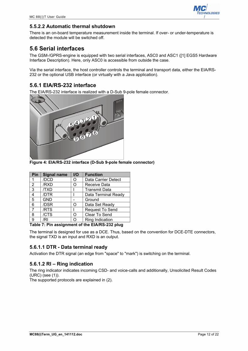
5.6.1 EIA/RS-232 interface The EIA/RS-232 interface is realized with a D-Sub 9-pole female connector.
Figure 4: EIA/RS-232 interface (D-Sub 9-pole female connector)
Pin Signal name I/O Function 1 /DCD O Data Carrier Detect 2 /RXD O Receive Data 3 /TXD I Transmit Data 4 /DTR I Data Terminal Ready 5 GND - Ground 6 /DSR O Data Set Ready 7 /RTS I Request To Send 8 /CTS O Clear To Send 9 /RI O Ring Indication
Table 7: Pin assignment of the EIA/RS-232 plug
The terminal is designed for use as a DCE. Thus, based on the convention for DCE-DTE connectors, the signal TXD is an input and RXD is an output.
5.6.1.1 DTR - Data terminal ready Activation the DTR signal (an edge from "space" to "mark") is switching on the terminal.
5.6.1.2 RI – Ring indication The ring indicator indicates incoming CSD- and voice-calls and additionally, Unsolicited Result Codes (URC) (see (1)). The supported protocols are explained in (2).
MC 88(i)T User Guide
MC88(i)Term_UG_en_141112.doc Page 13 of 22
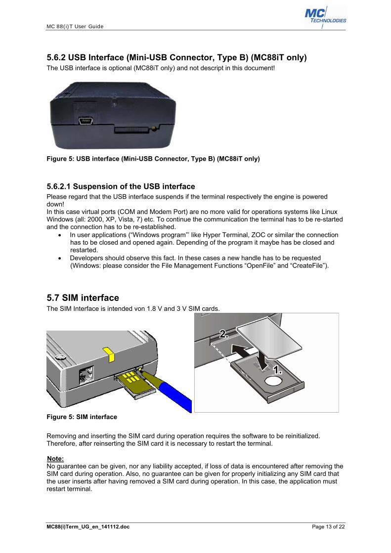
5.6.2 USB Interface (Mini-USB Connector, Type B) (MC88iT only) The USB interface is optional (MC88iT only) and not descript in this document!
Figure 5: USB interface (Mini-USB Connector, Type B) (MC88iT only)
5.6.2.1 Suspension of the USB interface Please regard that the USB interface suspends if the terminal respectively the engine is powered down! In this case virtual ports (COM and Modem Port) are no more valid for operations systems like Linux Windows (all: 2000, XP, Vista, 7) etc. To continue the communication the terminal has to be re-started and the connection has to be re-established.
In user applications (“Windows program”’ like Hyper Terminal, ZOC or similar the connection has to be closed and opened again. Depending of the program it maybe has be closed and restarted.
Developers should observe this fact. In these cases a new handle has to be requested (Windows: please consider the File Management Functions “OpenFile” and “CreateFile”).
5.7 SIM interface The SIM Interface is intended von 1.8 V and 3 V SIM cards.
Figure 5: SIM interface
Removing and inserting the SIM card during operation requires the software to be reinitialized. Therefore, after reinserting the SIM card it is necessary to restart the terminal. UNote: No guarantee can be given, nor any liability accepted, if loss of data is encountered after removing the SIM card during operation. Also, no guarantee can be given for properly initializing any SIM card that the user inserts after having removed a SIM card during operation. In this case, the application must restart terminal.

MC 88(i)T User Guide
MC88(i)Term_UG_en_141112.doc Page 14 of 22
5.8 Radio interface
Figure 6: Radio interface
For the application it is recommended to use only FME (female) connectors:
Figure 7: recommended antenna connector
5.9 LEDs
Figure 8: LEDs
There are LEDs to indicate the status and operation modes of the terminal. Additional to the following descriptions of the coding of the LEDs, the LEDs are flickering during the boot loader operation of the micro controller program (Firmware update) and during the configuration of the additional features (CCfg.exe, WatchDog etc.).
5.9.1 50B50B50B50BRed LED The red LED indicates the power control and the status of the micro controller. Operating status of the controller
LED mode
Description
Sleep mode Off Power supply connected, but not switched on Ignition flashing The engine is switched on. The communication via the serial interface will
be active after a few seconds. Active mode off The red LED is off. Usually the yellow LED is flashing (Table 9: Coding of
the yellow LED). Standby mode on The duration of the Standby Mode is roundabout 30 seconds.
If an ignition signal occurs (an active signal edge at pin 3 of the Western jack (5.4 Turn on) or an active edge on DTR (5.6.1.1 DTR - Data terminal ready)) the engine is activate immediately.
Table 8: Coding of the red LED

MC 88(i)T User Guide
MC88(i)Term_UG_en_141112.doc Page 15 of 22
5.9.2 Yellow LED The yellow LED is driven by the SYNC signal of the integrated GSM engine. The SYNC signal is configured by the AT Command "AT^SSYNC". For the purpose of the terminal it is recommend to use the AT Command "AT^SSYNC=1" or "AT^SSYNC=2" (1). LED mode Operation status
@ AT^SSYNC=1
Operation status @
AT^SSYNC=2 Permanently off
ME is in one of the following modes: POWER DOWN mode AIRPLANE mode CHARGE ONLY mode NON-CYCLIC SLEEP mode CYCLIC SLEEP mode with no
temporary wake-up event in progress 1)
ME is in one of the following modes: POWER DOWN mode AIRPLANE mode CHARGE ONLY mode
600 ms on / 600 ms off
Limited network service: No SIM card inserted or no PIN entered, or network search in progress, or ongoing user authentication, or network login in progress.
Same as for AT^SSYNC=1.
75 ms on / 3 s off
IDLE mode: The mobile is registered to the GSM network (monitoring control channels and user interactions). No call is in progress.
Same as for AT^SSYNC=1.
75 ms on / 75 ms off / 75 ms on / 3 s off
One or more GPRS PDP contexts activated.
Same as for AT^SSYNC=1.
500 ms on / 50 ms off
Packet switched data transfer is in progress
Same as for AT^SSYNC=1.
Permanently on
Depending on type of call: Voice call: Connected to remote
party. Data call: Connected to remote party
or exchange of parameters while setting up or disconnecting a call.
Same as for AT^SSYNC=1.
<n> ms on / <n> ms off 2)
Not possible: With AT^SSYNC=1, LED signalization is disabled in SLEEP mode.
SLEEP mode is activated (AT+CFUN parameter <fun> ≠ 1), but the ME is not registered to the GSM network (e.g. SIM not inserted or PIN not entered, and therefore, either no network service or only Limited Network Service is available.
25 ms on / 4 * <n> ms off 2)
Not possible: With AT^SSYNC=1, LED signalization is disabled in SLEEP mode.
SLEEP mode is activated (AT+CFUN parameter <fun> ≠ 1) while the ME is registered to the GSM network and in IDLE mode.
25 ms on / <m> ms off / 25 ms on / 3 * <m> ms off2)
Not possible: With AT^SSYNC=1, LED signalization is disabled in SLEEP mode.
SLEEP mode is activated (AT+CFUN parameter <fun> ≠ 1) while the ME is registered to the GSM network. Additionally, PDP context is activated.
1) When a temporary wake-up event (for example a call, a URC, a packet switched transfer) occurs in CYCLIC SLEEP mode the LED flashes according to the patterns listed above. 2) The duration of <n> and <m> depends on the network: In SLEEP mode, the module can only change its LED status during intermittent wake-up periods when listening to paging information from the base station. Therefore the values of <n> and <m> vary as follows: <n> = value from 471 ms to 2118 ms <m> = 3000 ms
Table 9: Coding of the yellow LED
MC 88(i)T User Guide
MC88(i)Term_UG_en_141112.doc Page 16 of 22
5.9.3 Blue LED (MC88iT only) The blue LED indicates the plugged USB connection.
6 AT commands All supported AT commands are described in [2] EGS5 AT Command Set.
7 Software-/Firmware-update Please differentiate between "Software" and "Firmware": Software "Software" means the program for GSM-/GPRS-engine.
An update is possible via the serial interface. The actual version can be identified with the AT command "ATI". The response is for example "CINTERION, EGS5, REVISION xx.xxx", with the Revision "xx.xxx". An update is possible with a Windows application.
Firmware "Firmware" means the program for the micro controller inside the terminal. An update is possible via the serial interface. The actual version cannot be identified with an AT command! An update is possible with a Windows application.
Update programs are available from your local distributer.
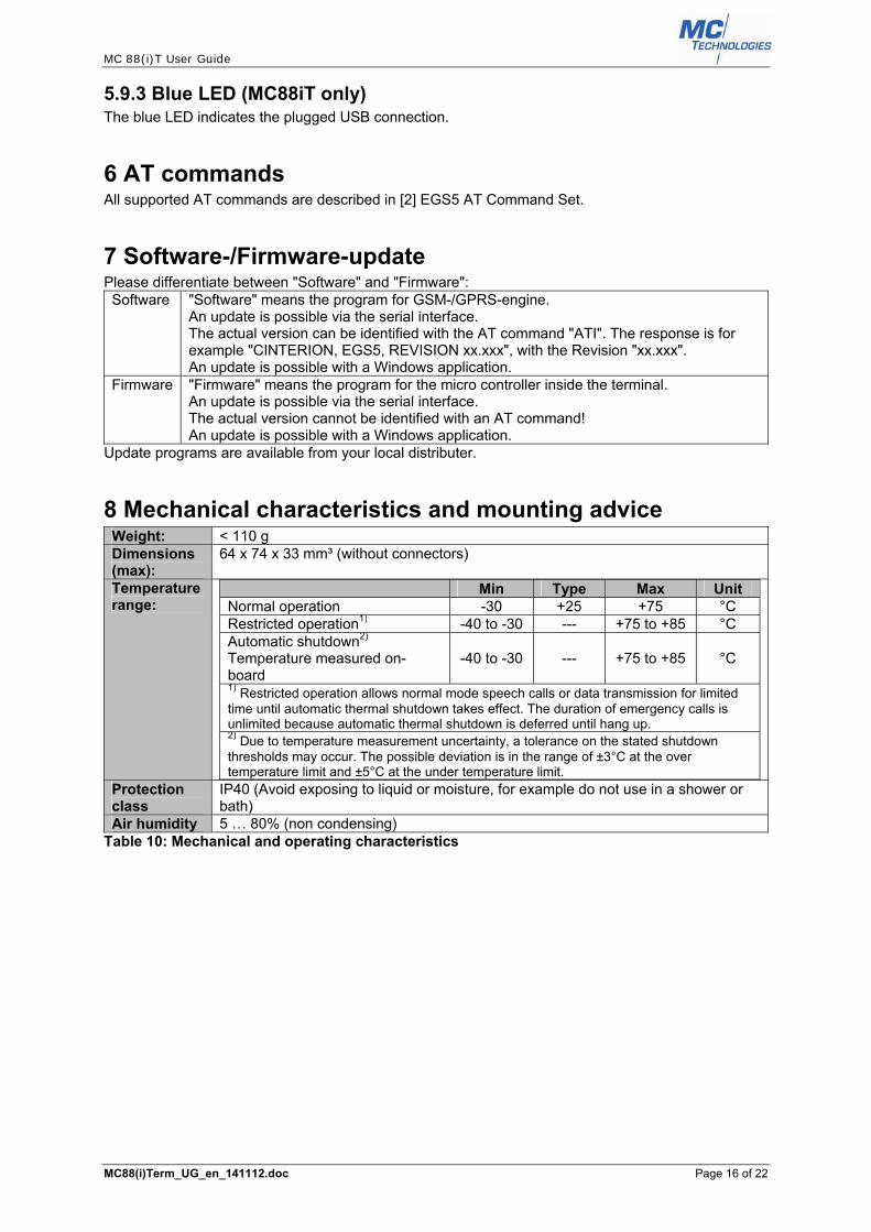
8 Mechanical characteristics and mounting advice Weight: < 110 g Dimensions (max):
64 x 74 x 33 mm³ (without connectors)
Temperature range:
Min Type Max Unit Normal operation -30 +25 +75 °C Restricted operation1) -40 to -30 --- +75 to +85 °C Automatic shutdown2)
Temperature measured on-board
-40 to -30 --- +75 to +85 °C
1) Restricted operation allows normal mode speech calls or data transmission for limited time until automatic thermal shutdown takes effect. The duration of emergency calls is unlimited because automatic thermal shutdown is deferred until hang up. 2) Due to temperature measurement uncertainty, a tolerance on the stated shutdown thresholds may occur. The possible deviation is in the range of ±3°C at the over temperature limit and ±5°C at the under temperature limit.
Protection class
IP40 (Avoid exposing to liquid or moisture, for example do not use in a shower or bath)
Air humidity 5 … 80% (non condensing) Table 10: Mechanical and operating characteristics
MC 88(i)T User Guide
MC88(i)Term_UG_en_141112.doc Page 17 of 22
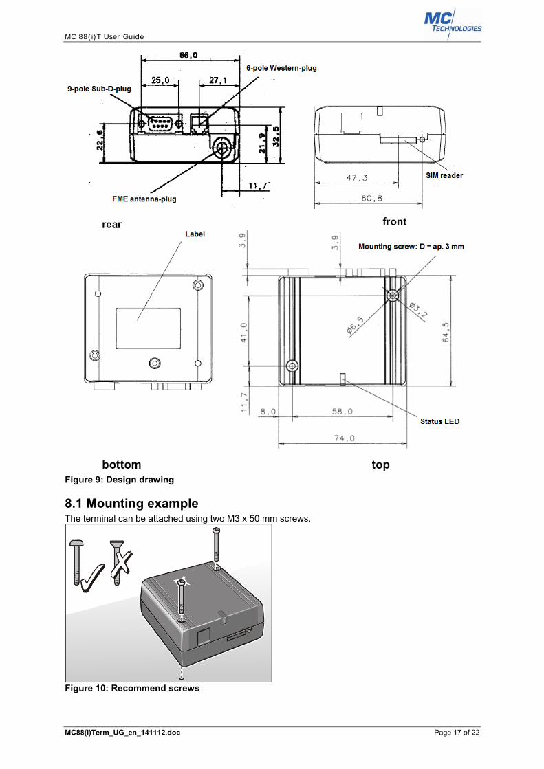
Figure 9: Design drawing
8.1 Mounting example The terminal can be attached using two M3 x 50 mm screws.
Figure 10: Recommend screws

MC 88(i)T User Guide
MC88(i)Term_UG_en_141112.doc Page 18 of 22
9 Electrical and environmental characteristics
9.1 Absolute maximum ratings Parameter Port / Description Min Max Unit
Supply Voltage PLUS 0 30 V Input voltage for on/off control lines
IGNITION, POWER DOWN 0 30 V
EIA/RS-232 input voltage range
/TXD, /DTR, /RTS -25 +25 V
/RXD, /CTS, /DSR, /DCD, /RING Immunity against discharge of static electricity
PLUS, IGNITION, POWER DOWN -8 +8 kV ESD-Protection: /TXD, /DTR, /RTS, /RXD, /CTS, /DSR, /DCD, /RING
-15 +15 kV
Protection class IP40 (Avoid exposing to liquid or moisture, for example do not use in a shower or bath)
IP40
Table 4: Absolute maximum ratings
9.2 34B34B34B34BOperation supply specification Parameter Description Conditions Min. Typ.2F2F2F2F
2 Max. UnitVPLUS Supply voltage PLUS to MINUS
measured at 6-pole Western jack plug (pin 1 to 6).
8 12 30 V
ÎPLUS Burst current4F3F3F3F
3 >1 A IPLUS Average supply current Power Down Mode @ 8 V 1,5 5,5 mA
@ 12V 1,5 5,5 mA @ 30V 1,7 5,5 mA
Sleep Mode @ 8 V 1,5 5,5 mA @ 12V 1,5 5,5 mA @ 30V 1,7 5,5 mA
Table 5: Operation supply specification
Parameter Description Conditions Unit
Mode GSM frequency RF power3F4F4F4F
4
Input Voltage5
8 V 12 V
30 V
IPLUS Average supply current
IDLE mode (GSM / GPRS) 50 50 50 mA
GSM CSD mode 850/900 MHz 2 W 160 115 60 mA
1800/1900 MHz 1 W 130 100 50 mAGPRS Data mode Class 8 (1 TX, 4 RX)
850/900 MHz 2 W 170 120 70 mA1800/1900 MHz 1 W 130 100 50 mA
GPRS Data mode Class10 (2 TX, 3 RX)
850/900 MHz 2 W 300 200 100 mA1 W 250 170 80 mA
1800/1900 MHz1 W 200 140 70 mA
0,5 W 180 130 70 mA
GPRS Data mode Class 12 (4TX, 1RX)
850/900 MHz 1 W 340 230 110 mA
0,5 W 300 200 100 mA
1800/1900 MHz0,5 W 250 180 90 mA0,25 W 230 160 80 mA
Table 6: Average supply current 2 The Parameters are tested and calculated. In practice they can vary depending of the antenna signal quality and the distance between the terminal and the GSM base station! 3 The value and duration of the burst current depend on several conditions. Pay attention to use only power supplies that comply with the conditions in this document! 4 The (maximal) RF power is adjustable by the command AT^SCFG="Radio/OutputPowerReduction"[, <ropr>] (see [2] EGS5 AT Command Set) 5 The Parameters are tested and calculated. In practice they can vary depending of the antenna signal quality and the distance between the terminal and the GSM base station! Peak levels are possible up to 1.4 A!

MC 88(i)T User Guide
MC88(i)Term_UG_en_141112.doc Page 19 of 22
9.3 On-board operating temperature of build in GSM engine Parameter Min Typ. Max Unit
Normal operation -30 +25 +75 °C Restricted operation -50 to -30 --- +75 to +85 °C Automatic thermal shutdown ≤-30 --- ≥+75 °C
Table 14: On-board operating temperature of build in GSM engine
9.4 On/off control line specification Parameter Description Conditions Min Typ. Max Unit Vin,high IGNITION, POWER DOWN 2,0 V Vin,low IGNITION, POWER DOWN 1,5 RIN IGNITION, POWER DOWN 100 kΩ
Table 15: On/off control line specification
9.5 EIA/RS-232 interface specification Parameter Description Conditions
(TA=+25°C) Min Typ. Max Unit
VOUT Transmitter output voltage for /RXD, /CTS, /DSR, /DCD, /RING
All transmitter outputs loaded with 3kΩto ground
±5 ±5.4 V
ROUT Transmitter output resistor for /RXD, /CTS, /DSR, /DCD, /RING
300 10M Ω
RIN Receiver input resistor for /TXD, /RTS, /DTR
3 5 7 kΩ
Vin Input Voltage Range -25 +25 V Vin,low Input threshold voltage low 0.6 1.2 V Vin,high Input threshold voltage high 1.5 2.4 V Vin,hysteresis Input hysteresis 0.3 V Baud rate Maximum data rate RL=3kΩ, CL=250pF 1000 kbps
Table 76: EIA/RS-232 interface specification
9.6 USB interface specification The USB interface is optional (MC88iT only) and not descript in this document!

MC 88(i)T User Guide
MC88(i)Term_UG_en_141112.doc Page 20 of 22
10 Power supplies If you do not use the special power supply for the terminal, for example an alternative wall adapter please verifies the conditions and the necessary parameters.
• A voltage of 12 VDC is strictly recommended. • The minimum output current should be 1.2 Ampere or more. • The GSM burst transmissions are causing pulse currents at the power supply input. • The power supply has to be protected against short circuit. • Additional low-ESR Capacitors could be necessary. • At higher voltages it is recommend placing a serial resistor into the power line.
11 Over temperature Data transmission for a longer time can cause higher temperature of the GSM-/GPRS-engine. If the on-board temperature rises over the limited rating, the engine switches off automatically. To avoid over temperature take care of the cooling.
• Do not cover the terminal! • Take care for suitable ambient temperature. • Use only recommended antennas. • Use power supplies with an output voltage between 12 VDC and 15 VDC.
12 Regulatory and type approval information
12.1 Directives and standards The GSM-/GPRS-engine has been approved to comply with the directives and standards listed in [1] EGS5 Hardware Interface Description. It is the responsibility of the application manufacturer to ensure compliance of the final product with all provisions of the applicable directives and standards as well as with the technical specifications provided in [1] EGS5 Hardware Interface Description.
12.2 SAR requirements specific to portable mobiles Mobile phones, PDAs or other portable transmitters and receivers incorporating a GSM module must be in accordance with the guidelines for human exposure to radio frequency energy. This requires the Specific Absorption Rate (SAR) of portable GSM-/GPRS-applications to be evaluated and approved for compliance with national and/or international regulations.

MC 88(i)T User Guide
MC88(i)Term_UG_en_141112.doc Page 21 of 22
13 Special features for Java applications There are several special functions to improve the operation of the terminal – especially for java applications. These functions are realized with the on-board controller circuit.
13.1 Configuration the special functions with "Ccfg.exe" The configuration occurs with the program "Ccfg.exe".
Figure 11: "Ccfg.exe"
13.2 Watchdog The "Watchdog" resets the GSM-/GPRS-engine and also the Java application on the engine in the case of a fault condition, such as a hang. The Java application has to trigger the "Watchdog" by toggling GPIO1 (configured as an output pin) in defined intervals. If the toggling is missing the Watchdog timer overrun and the controller automatically resets the engine, because a hang up of the Java application is supposed. The "Watchdog" function is an option that has to be enabled with the Windows program "Ccfg.exe" (13.1 Configuration the special functions with "Ccfg.exe") and also the duration of the watchdog timer interval. In most cases it is recommend activating the "Watchdog" function together with "Auto-Start" function (13.3 Auto-Start)!

MC 88(i)T User Guide
MC88(i)Term_UG_en_141112.doc Page 22 of 22
13.3 Auto-Start In autonomous application without personal control a fall out of the terminal perhaps would occur in dramatic effects - even in the case of only a little problem like a small power failure. To prevent the terminal and of course the Java applications from longer breakdowns the "Auto-Start" functions re-starts the GSM-/GPRS-engine in the case that it is switched off. If the controller logic recognizes the off-state of the engine, it switched on the engine again automatically. The "Auto-Start" function is an option that has to be enabled with the Windows program "Ccfg.exe" (13.1 Configuration the special functions with "Ccfg.exe"). Please refer to the AT command 'AT^SCFG="Userware/Autostart/AppName" ' in [3] Java User's Guide and [2] EGS5 AT Command Set for additional notes.
14 Programming GPIOs in (Java) applications Only GPIO1 (index '0'!) is used for the "Watchdog"-function (13.2 Watchdog). Other GPIOs should not be used by user applications! Please refer to the chapter "GPIO Commands" in [2] EGS5 AT Command Set. Before or during the start-up process of the terminal respectively the engine the GPIOs are in an undefined state and sometimes they float! The sequence to set the GPIOs in a defined status requires only a few AT commands.
AT command Description AT^SPIO=1 Open general purpose IO driver
Note: The command must be executed before any other GPIO command can be used.
AT^SCPIN=1,0,1,0 Pin configuration: AT^SCPIN=<mode>,<pin_id>,<direction>,<startValue> Open (<mode> =1) GPIO1 (<pin_id> = 0) as an output (<direction> = 1) and set a low output level (<startValue > = 0)
Table 17: GPIO-pin configuration
After this configuration, the output level of the GPIO can be changed with only on AT command: AT
command Description
AT^SSIO=0,0 Set IO state of a specified pin: AT^SSIO = <io_id>,<value> Set the state of GPIO1 (<pin_id> = 0) to a low output level (<value > = 0)
AT^SSIO=0,1 Set IO state of a specified pin: AT^SSIO = <io_id>,<value> Set the state of GPIO1 (<pin_id> = 0) to a high output level (<value > = 1)
Table 8: GPIO output setting
15 Programming hints and warnings Do not use (internal) hardware features of the integrated GSM engine like Analog-Digital-
Converter, Pulse-Width modulation, charging etc. Do not use other GPIOs than GPIO1 (see 13.2 Watchdog, page 21). The yellow LED is controlled by a signal from the GSM engine (see Fehler! Verweisquelle
konnte nicht gefunden werden. Yellow LED, page Fehler! Textmarke nicht definiert.). Never use the command "AT^SSYNC=0" (see [2] EGS5 AT Command Set).
The Real Time Clock of the engine is only powered if the engine is switched on. There is
no (power) backup. Thus the write command "AT+CCLK=<time>" and read command "AT+CCLK?" have no sense (see [2] EGS5 AT Command Set).
The command "AT+CALA=<time>[, <n>[, <type>[, <text>]]]" (see [2] EGS5 AT Command Set) should never be used!
The I2C bus and SPI bus of the engine should not be used. They are used internal of the
terminal and incorrect usage could damage the terminal!