MC2 Match Controller Operator Manual Ver. 1 · The MC2 Matching Network Controller is designed for...
58
1925 Worthington Ave Clairton Pa, 15025 Telephone: (800) 245-1656 Fax: (412) 384-2745 MC2 MATCHING NETWORK CONTROLLER OPERATOR’S MANUAL Revision: 1.01 Standard Configuration Document Number 6200070000
Transcript of MC2 Match Controller Operator Manual Ver. 1 · The MC2 Matching Network Controller is designed for...

1925 Worthington Ave
Clairton Pa, 15025 Telephone: (800) 245-1656
Fax: (412) 384-2745
MC2
MATCHING NETWORK
CONTROLLER
OPERATOR’S MANUAL
Revision: 1.01
Standard Configuration
Document Number 6200070000

MC2 MATCHING NETWORK CONTROLLER OPERATOR’S MANUAL
Page 1 Kurt J. Lesker Company
6200070000 Rev. 1.01
Introduction
Thank you for acquiring your new KJLC IPS product. The MC2 Matching Network
Controller has been designed to provide the best value, ease of operation, and reliability
for plasma and processing systems. This manual covers specifications, installation, and
operation of the MC2 Matching Network Controller.
Information
For technical questions, application assistance, or additional information, contact our
customer service department or nearest customer service representative.
Service
Customer Service Representatives are available to answer your technical questions.
Should your KJLC product require service, contact the nearest KJLC service
representative for a Return Materials Authorization Number. Any returned equipment
should be sent freight prepaid.
Please note: Equipment returned to us without prior authorization or without a Return
Materials Authorization (RMA) number visible on the outside of the package will be
refused.
How to Contact Us Our address, telephone, and fax numbers are listed below. Office hours are Monday through Friday, 8:00am to 8:00pm, United States Eastern Time
Kurt J. Lesker Company
1925 Worthington Ave.
Clairton Pa, 15025
Telephone: 800-245-1656
Fax: 412-384-2745
Proprietary Information Notice
This document contains information proprietary to KJLC. This document shall not be reproduced or its contents disclosed without the written permission of KJLC. This
notice shall appear in all copies.

MC2 MATCHING NETWORK CONTROLLER OPERATOR’S MANUAL
Page 2 Kurt J. Lesker Company
6200070000 Rev. 1.01
TABLE OF CONTENTS
Safety Notes ………………………………………………………………………3
MC2 Matching Network Controller Features ………………………………………5
Physical Dimensions ………………………………………………………6
Installation ………………………………………………………………………8
Front Panel Controls and Display ………………………………………………10
Operation ………………………………………………………………………12
Basic Front Panel ………………………………………………………………12
Configuring Programmable Parameters ………………………………………14
Programmable Parameter Reference ………………………………………14
Programmable Parameter Details ………………………………………………16
Rear Panel Controls and Connections………………………………………………26
AC Mains Voltage Change Procedure ………………………………………27
Typical Interface Connections ………………………………………………36
Typical Configurations ………………………………………………………42
Maintenance ………………………………………………………………………48
Problem Solving ………………………………………………………………49
Matching Network Range Configuration ………………………………………51
Phase and Magnitude Sensor Adjustment Procedure ………………………52
Technical Data ………………………………………………………………53
KJLC 1 Year Limited Warranty ………………………………………………54
Obtaining Service for the MC2 Matching Network Controller ………………54
Glossary of Terms ………………………………………………………………57
Revision History ………………………………………………………………58

MC2 MATCHING NETWORK CONTROLLER OPERATOR’S MANUAL
Page 3 Kurt J. Lesker Company
6200070000 Rev. 1.01
=
Safety Notes
The MC2 Matching Network Controller has been designed and tested to meet strict safety
requirements. These include independent lab examination and approval, and compliance
to established standards. Please read the following instructions carefully before operating
the Matching Network Controller and refer to them as needed to ensure the continued
safe operation of the Matching Network Controller.
Follow all warnings and instructions marked on or supplied with the product.
Safety Symbols:
! = CAUTION HIGH
= VOLTAGE
RADIO FREQUENCY =
ENERGY HAZARD
PROTECTIVE
GROUND
EQUIPOTENTIAL BONDING =
POINT
Unplug or disconnect this equipment from the power source before cleaning or re-
configuring the AC mains voltage.
Do not use this equipment near water, wet locations, or outdoors.
Do not place this equipment on an unstable cart, stand, or table. The MC2 Matching
Network Controller may fall, causing personal injury or damage to the Matching
Network Controller.
This product is equipped with a 3-wire power cord and grounding type plug. This is a
safety feature. To avoid electric shock, this unit must be connected to the power source
in compliance with the National Electrical Code ANSI C1 and/or any other codes
applicable to the user. Improper installation may result in a shock or fire hazard.
It is the responsibility of the installer to provide a proper protective ground from the Matching Network Controller to earth ground, in accordance with local and national
electrical codes, and any other codes applicable to the user.
The Matching Network Controller should be operated from the type of power source
indicated by the rear panel voltage selector. If you are not sure of the type of power
available, consult an electrician or your local power company.
The power supply cord and plug is the disconnect device for this equipment. If the
plug is removed from the cord and the power cord is hard wired to the power source, it is
the responsibility of the installer to provide a disconnect device.
Do not allow anything to rest on the power cord or interconnecting cables. Do not locate the Matching Network Controller where persons will step on the power or
interconnecting cables.
Slots and Openings in the equipment’s chassis are provided for ventilation. To ensure
reliable operation of the MC2 Matching Network Controller, these openings must not be
blocked, covered, or restricted. Restricting the air inlets or exhaust will cause the unit to
overheat. Sustained over temperature conditions may degrade or damage the unit.

MC2 MATCHING NETWORK CONTROLLER OPERATOR’S MANUAL
Page 4 Kurt J. Lesker Company
6200070000 Rev. 1.01
Never push objects of any kind into the slots and openings of the Matching Network
Controller’s enclosure. They may touch dangerous voltage points or short out parts,
which could result in a fire or electric shock.
Never spill liquid of any kind on or into the Matching Network Controller.
Never remove covers or guards that require a tool for removal. There are no operator
serviceable areas within these covers. Refer servicing to qualified service personnel.
! CAUTION!
ELECTRICAL SHOCK HAZARD PRESENT
INSIDE UNIT AND AT THE MAINS INPUT
CONNECTOR .
DO NOT REMOVE COVERS. REFER
SERVICING TO QUALIFIED
SERVICE PERSONNEL.

MC2 MATCHING NETWORK CONTROLLER OPERATOR’S MANUAL
Page 5 Kurt J. Lesker Company
6200070000 Rev. 1.01
MC2 Matching Network Controller Features
The MC2 Matching Network Controller is intended for use with KJLC AT-Series
Automatic Impedance Matching Networks.
The MC2 Matching Network Controller powers and controls the operation of the KJLC
AT-Series Automatic Impedance Matching Networks, provides operator- accessible
controls, a visual display of matching network status, and a control interface to the user’s
processing system. Other MC2 features are listed below:
• ½ Rack 2U High Package
• 110VAC or 220VAC AC Mains, field selectable
• Bright, easy to read 4 Line Vacuum Fluorescent Display, capable of displaying
matching network status, RF Power Supply Status, RF or DC Probe Voltage,
Phase and magnitude error signals
• Front panel controls for capacitor positioning, mode selection, and programming
• Scaleable Forward and Reflected power metering (requires interface connection to RF Power Supply)
• Scalable RF and DC Probe display
• Programmable capacitor position presets
• Programmable capacitor position limits
• Remote controlled via analog system interface connector
• Matching network capacitors can be manually positioned from front panel
controls while unit is in “Automatic” mode
• Loop-through control connectors for the RF Power Supply – simplifies
connection of RF and DC Probes, provides forward power, reflected power, and
power setpoint monitoring
• Adjustable error amplifier gain
• Rear panel Phase and Magnitude error signal test points
• Limit Condition Backout: The MC2 Controller reverses the matching network’s motors for a brief interval when a minimum or maximum position limit condition
has been reached, allowing the matching network to re-tune, thus minimizing
“stuck” network conditions. The limit condition feature can be enabled/disabled from the front panel.

MC2 MATCHING NETWORK CONTROLLER OPERATOR’S MANUAL
Page 6 Kurt J. Lesker Company
6200070000 Rev. 1.01
0.0
0 [0.0
0]
0.1
6 [4.0
6]
0.0
0 [
0.0
0]
0.3
1 [
7.9
2]
9.1
9 [
23
3.3
5]
9.5
0 [
24
1.3
0]
12.9
0 [3
27
.76]
13.0
7 [3
31
.90]
Physical Dimensions
3.50 [88.90]
2.63 [66.68]
0.25 x 0.41
[6.35 x 10.41]
0.88 [22.23]
0.00 [0.00]
Front View, MC2 Matching Network Controller
Dimensions in Inch [mm]
Side View, MC2 Matching Network Controller
Dimensions in Inch [mm]

MC2 MATCHING NETWORK CONTROLLER OPERATOR’S MANUAL
Page 7 Kurt J. Lesker Company
6200070000 Rev. 1.01
0.0
0 [
0.0
0]
0.6
3 [
15.8
8]
8.8
8 [
225.4
3]
9.5
0 [
241.3
0]
3.50 [88.90]
3.47 [88.14]
0.00 [0.00]
Rear View, MC2 Matching Network Controller
Dimensions in Inch [mm]

MC2 MATCHING NETWORK CONTROLLER OPERATOR’S MANUAL
Page 8 Kurt J. Lesker Company
6200070000 Rev. 1.01
Installation:
Recommended mounting:
The MC2 Matching Network Controller is designed for placement on a tabletop or within an equipment rack, with another ½ Rack 2U piece of equipment, in a clean
environment. The table or equipment rack must be capable of supporting the full
weight of the unit. The MC2 Controller is supplied with an integral ½ Rack
Mounting Bracket. The user is responsible for providing mounting hardware.
Note: the weight of the MC2 Matching Network
Controller is 7.5 pounds (3.2 kg)
Optional Mounting:
One (1) MC2 Controller may be mounted in a 19” equipment rack with the use of the optional single rack mount kit, KJLC Part Number 7300080000. The
equipment rack must be capable of supporting the full weight of the unit.
Two (2) MC2 Controllers may be mounted in a 19” equipment rack with the use of
the dual rack mount kit, KJLC Part Number 7300070000. The equipment rack must be capable of supporting the full weight of two (2) MC2 units.
Supplied Accessories:
Description Quantity KJLC Part Number
½ Rack Mount Bracket Kit (2 brackets and
4 screws)
1 7300120000
Power Cord (for 110V models)
IEC320-13 Receptacle to NEMA 5-15 Plug
* 4500680000
Power Cord (for 220V models)
IEC320-13 Receptacle to un-terminated
wires
* 4500730000
* Only 1 power cord is supplied with the MC2 Matching Network Controller. The
power cord type depends on the line voltage ordered.
MC2 MATCHING NETWORK CONTROLLER OPERATOR’S MANUAL
Page 9 Kurt J. Lesker Company
6200070000 Rev. 1.01
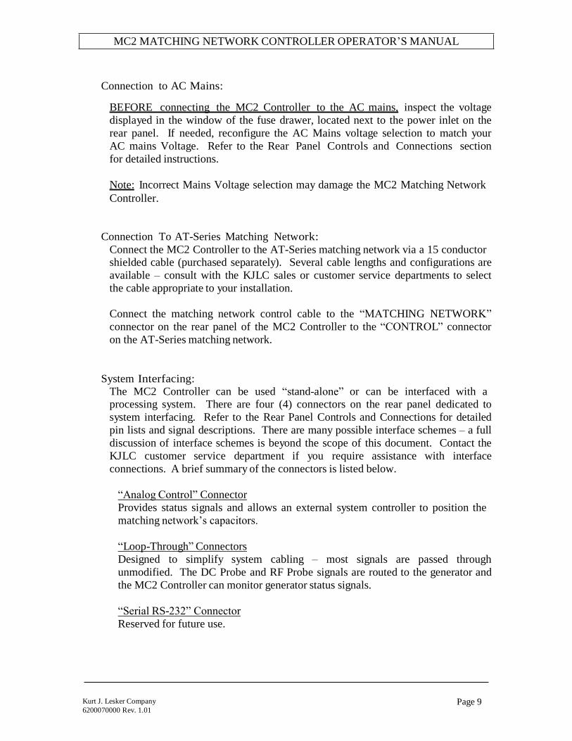
Connection to AC Mains:
BEFORE connecting the MC2 Controller to the AC mains, inspect the voltage
displayed in the window of the fuse drawer, located next to the power inlet on the
rear panel. If needed, reconfigure the AC Mains voltage selection to match your
AC mains Voltage. Refer to the Rear Panel Controls and Connections section
for detailed instructions.
Note: Incorrect Mains Voltage selection may damage the MC2 Matching Network
Controller.
Connection To AT-Series Matching Network:
Connect the MC2 Controller to the AT-Series matching network via a 15 conductor shielded cable (purchased separately). Several cable lengths and configurations are
available – consult with the KJLC sales or customer service departments to select
the cable appropriate to your installation.
Connect the matching network control cable to the “MATCHING NETWORK”
connector on the rear panel of the MC2 Controller to the “CONTROL” connector
on the AT-Series matching network.
System Interfacing: The MC2 Controller can be used “stand-alone” or can be interfaced with a processing system. There are four (4) connectors on the rear panel dedicated to
system interfacing. Refer to the Rear Panel Controls and Connections for detailed
pin lists and signal descriptions. There are many possible interface schemes – a full
discussion of interface schemes is beyond the scope of this document. Contact the
KJLC customer service department if you require assistance with interface
connections. A brief summary of the connectors is listed below.
“Analog Control” Connector
Provides status signals and allows an external system controller to position the
matching network’s capacitors.
“Loop-Through” Connectors
Designed to simplify system cabling – most signals are passed through
unmodified. The DC Probe and RF Probe signals are routed to the generator and
the MC2 Controller can monitor generator status signals.
“Serial RS-232” Connector
Reserved for future use.

MC2 MATCHING NETWORK CONTROLLER OPERATOR’S MANUAL
Page 10 Kurt J. Lesker Company
6200070000 Rev. 1.01
Front Panel Controls and Display:
DISPLAY 5 7 8 9
KJLC Industrial Power Systems
TUN
P-TN
PH:
49%
25%
-2mV
LOAD
P-LD
MAG
35%
50%
+5mV
MIN MAX
MIN MAX
MAN
MAN
LOAD
PGM DOWN UP ENT TUNE
MC2 AUTOMATIC MATCHING NETWORK CONTROLLER
POWER
I O
1 2 3 4 6 10 11 12
13
Buttons
Item Name Description
1 Program/Run Toggles the MC2 Controller between the RUN mode and
PROGRAM mode. In Program mode, display line 3
changes to show Programmable Menu Entry Options. The
button legend changes from “PGM” to “RUN” when in
the Program mode.
2 Down Moves down the programming menu
3 Up Moves up the programming menu
4 Enter Programs (saves) changes made to a parameter
5 Value Up Changes Parameter Value - Increment
6 Value Down Changes Parameter Value - Decrement
7 Load Min Manually positions Load cap towards minimum
capacitance
8 Load Max Manually positions Load cap towards maximum
capacitance
9 Load Mode Selects Load capacitor automatic or manual mode
10 Tune Min Manually moves Tune cap to minimum capacitance

MC2 MATCHING NETWORK CONTROLLER OPERATOR’S MANUAL
Page 11 Kurt J. Lesker Company
6200070000 Rev. 1.01
11 Tune Max Manually moves Tune cap to maximum capacitance
12 Tune Mode Selects Tune capacitor automatic or manual mode
13 Power Enables / Disables Mains Power
Display The front panel display shows status of the matching network capacitor positions and provides legends for the keypad. Two of the four display lines are user configurable.
There are four (4) display items available for the user configurable display lines, but
only two (2) display items can be shown at one time.
Line Description
1 Tune and Load Capacitor positions 1 to 100%, or 0% if matching
network control cable has been disconnected or capacitor position
feedback signal is missing.
2 User Configurable Display Line
Displays Tune Capacitor Preset Point, Load Capacitor Preset Point
(User enabled or disabled)
Displays Phase and MAGnitude error signal Voltage
(User enabled or disabled)
Displays Generator’s Forward power setpoint and Reflected power (RF
OFF condition) or Actual Forward power and reflected power (RF ON
condition). (User enabled or disabled)
Displays DC Voltage Probe or RF Voltage Probe output
(User enabled or disabled)
3 User Configurable Display Line
In RUN mode:
Displays Tune Capacitor Preset Point, Load Capacitor Preset Point
(User enabled or disabled)
Displays Phase and MAGnitude error signal Voltage
(User enabled or disabled)
Displays Generator’s Forward power setpoint and Reflected power
(RF Off condition) or Actual Forward power and reflected power (RF
ON condition). (User enabled or disabled)
Displays DC Voltage Probe or RF Voltage Probe output
(User enabled or disabled)
In PROGRAM mode:
Displays a programmable parameter and its current setting.
4 Keypad Menu – button legends change depending on mode

MC2 MATCHING NETWORK CONTROLLER OPERATOR’S MANUAL
Page 12 Kurt J. Lesker Company
6200070000 Rev. 1.01
Operation
Front panel operation of the MC2 Matching Network Controller is simple. This section
describes the use and operation of the front panel controls in a “how to…” manner. Refer
to the front panel illustration on the previous page for item references.
Basic Front Panel Operation
Mains Power On/Off
Press the POWER button (item 13) to enable mains power – the front panel display
will illuminate and momentarily display the firmware revision and copyright. Press
the POWER button again to disable mains power.
To Select CAPACITOR MODE:
The MC2 Controller has two (2) capacitor control modes: Automatic (AUTO) and
Manual (MAN). The Load and Tune capacitor control modes are independent of
each other.
The Automatic mode responds to an error signal from the matching network’s Phase
and Magnitude sensor, automatically adjusting the associated matching network
capacitor to minimize reflected power to the RF generator. The MIN and MAX
capacitor positioning buttons are active in Automatic mode – this is useful for system
set-up.
The automatic mode will only respond when an RF signal is applied to the matching
network.
The Manual mode disables automatic operation of the respective matching network
capacitor. The MIN and MAX capacitor positioning buttons may be used to
manually position the matching network capacitor.
LOAD:
To change the mode of the Load capacitor, press the LOAD mode select button
(item 9) on the front panel. The indicator lamp above the button will change to
show the current operational mode.
TUNE:
To change the mode of the Tune capacitor, press the TUNE mode select button
(item 12) on the front panel. The indicator lamp above the button will change to
show the current operational mode.
Note: The mode selection is saved when the MC2 Controller is powered down – it
will power-up in the same mode.
MC2 MATCHING NETWORK CONTROLLER OPERATOR’S MANUAL
Page 13 Kurt J. Lesker Company
6200070000 Rev. 1.01
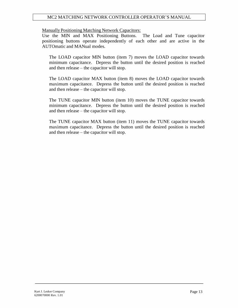
Manually Positioning Matching Network Capacitors:
Use the MIN and MAX Positioning Buttons. The Load and Tune capacitor
positioning buttons operate independently of each other and are active in the
AUTOmatic and MANual modes.
The LOAD capacitor MIN button (item 7) moves the LOAD capacitor towards
minimum capacitance. Depress the button until the desired position is reached
and then release – the capacitor will stop.
The LOAD capacitor MAX button (item 8) moves the LOAD capacitor towards
maximum capacitance. Depress the button until the desired position is reached
and then release – the capacitor will stop.
The TUNE capacitor MIN button (item 10) moves the TUNE capacitor towards
minimum capacitance. Depress the button until the desired position is reached
and then release – the capacitor will stop.
The TUNE capacitor MAX button (item 11) moves the TUNE capacitor towards
maximum capacitance. Depress the button until the desired position is reached
and then release – the capacitor will stop.
MC2 MATCHING NETWORK CONTROLLER OPERATOR’S MANUAL
Page 14 Kurt J. Lesker Company
6200070000 Rev. 1.01
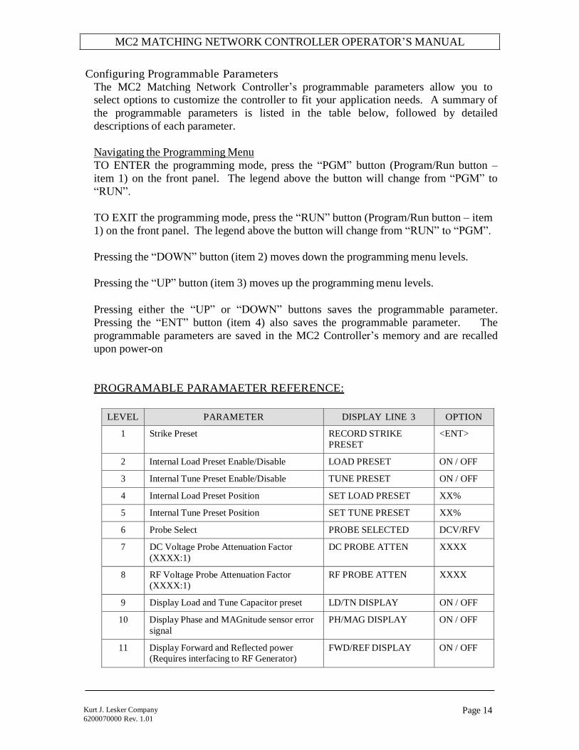
Configuring Programmable Parameters
The MC2 Matching Network Controller’s programmable parameters allow you to select options to customize the controller to fit your application needs. A summary of
the programmable parameters is listed in the table below, followed by detailed
descriptions of each parameter.
Navigating the Programming Menu
TO ENTER the programming mode, press the “PGM” button (Program/Run button –
item 1) on the front panel. The legend above the button will change from “PGM” to
“RUN”.
TO EXIT the programming mode, press the “RUN” button (Program/Run button – item
1) on the front panel. The legend above the button will change from “RUN” to “PGM”.
Pressing the “DOWN” button (item 2) moves down the programming menu levels.
Pressing the “UP” button (item 3) moves up the programming menu levels.
Pressing either the “UP” or “DOWN” buttons saves the programmable parameter.
Pressing the “ENT” button (item 4) also saves the programmable parameter. The
programmable parameters are saved in the MC2 Controller’s memory and are recalled
upon power-on
PROGRAMABLE PARAMAETER REFERENCE:
LEVEL PARAMETER DISPLAY LINE 3 OPTION
1 Strike Preset RECORD STRIKE
PRESET
<ENT>
2 Internal Load Preset Enable/Disable LOAD PRESET ON / OFF
3 Internal Tune Preset Enable/Disable TUNE PRESET ON / OFF
4 Internal Load Preset Position SET LOAD PRESET XX%
5 Internal Tune Preset Position SET TUNE PRESET XX%
6 Probe Select PROBE SELECTED DCV/RFV
7 DC Voltage Probe Attenuation Factor
(XXXX:1)
DC PROBE ATTEN XXXX
8 RF Voltage Probe Attenuation Factor
(XXXX:1)
RF PROBE ATTEN XXXX
9 Display Load and Tune Capacitor preset LD/TN DISPLAY ON / OFF
10 Display Phase and MAGnitude sensor error
signal
PH/MAG DISPLAY ON / OFF
11 Display Forward and Reflected power
(Requires interfacing to RF Generator)
FWD/REF DISPLAY ON / OFF

MC2 MATCHING NETWORK CONTROLLER OPERATOR’S MANUAL
Page 15 Kurt J. Lesker Company
6200070000 Rev. 1.01
LEVEL PARAMETER DISPLAY LINE 3 OPTION
12 Display RF or DC Voltage Probe
(Displays Probe selected at level 6)
RF/DCV DISPLAY ON / OFF
13 Forward Power Full Scale Wattage.
Assumes generator’s Forward power
monitor signal is set for 5.00V at full scale.
Instructs the MC2 Controller to display 0-
9999 Watts for a 5.00VDC signal.
(Requires interfacing to RF Generator)
FORWARD F.S. 0-9999
14 Reflected Power Full Scale Wattage.
Assumes generator’s Reflected power
monitor signal is set for 5.00V at full scale.
Instructs the MC2 Controller to display 0-
9999 Watts for a 5.00VDC signal.
(Requires interfacing to RF Generator)
REFLECTED F.S. 0-9999
15 Load Capacitor Programmable High Limit
(Factory Default: 98%)
LOAD LIMIT HIGH 2-98%
16 Load Capacitor Programmable Low Limit
(Factory Default 2%)
LOAD LIMIT LOW 2-98%
17 Tune Capacitor Programmable High Limit
(Factory Default: 98%)
TUNE LIMIT HIGH 2-98%
18 Tune Capacitor Low Limit
(Factory Default: 2%)
TUNE LIMIT LOW 2-98%
19 BACKOUT feature Enable / Disable
(Factory Default: Enabled)
BACKOUT ENABLED /
DISABLED
20 RFON Signal Polarity
Used to select RF Generator RF ON and RF
OFF states for displaying Forward setpoint
or Forward Power
(Requires interfacing to RF Generator)
Low Input = Active Low RF ON polarity
(default)
High Input = Active High RF ON polarity
RFON = LOW
INPUT /
HIGH
INPUT
21 Factory Settings – Enter secure setup menu.
Enter passcode.
No User Adjustments
ENT SECURE SETUP XXX

MC2 MATCHING NETWORK CONTROLLER OPERATOR’S MANUAL
Page 16 Kurt J. Lesker Company
6200070000 Rev. 1.01
PROGRAMMABLE PARAMETER DETAILS:
1. Record Strike Preset
Used in conjunction with LOAD and TUNE presets – records the current capacitor
positions for use with the preset feature.
The third line of the front panel display changes to “RECORD STRIKE PRESET”.
Position the Load and Tune capacitors to the desired position for striking a plasma.
Press the Enter “ENT” button (item 4) on the front panel. The current load and tune
capacitor positions are recorded as the strike preset and saved in non-volatile
storage.
Use the UP or DOWN buttons to select another parameter, or press the RUN button
return to normal operation.
2. Internal Load Preset Enable/Disable
Selects the source of the Load Capacitor preset position. The MC2 Controller will
position the Load Capacitor to the selected preset when the Analog Control
connector PRELOAD signal (pin 2) is activated.
The LOAD PRESET ON state instructs the MC2 Controller to position the Load
Capacitor to the Load Preset value stored in the MC2 Controller’s memory.
The LOAD PRESET OFF state instructs the MC2 Controller to position the Load
Capacitor to the preset position value present at the Analog Control connector
LOADPSETV signal (pin 13).
Use the VALUE UP button (item 5) or VALUE DOWN button (item 6) to select
the desired LOAD PRESET state.
Press the Enter “ENT” button (item 4) on the front panel. The displayed Load
Preset status is saved in non-volatile storage.
Use the UP or DOWN buttons to select another parameter, or press the RUN button
return to normal operation.
3. Internal Tune Preset Enable/Disable
Selects the source of the Tune Capacitor preset position. The MC2 Controller will
position the Tune Capacitor to the selected preset when the Analog Control
connector PRETUNE signal (pin 5) is activated.

MC2 MATCHING NETWORK CONTROLLER OPERATOR’S MANUAL
Page 17 Kurt J. Lesker Company
6200070000 Rev. 1.01
The TUNE PRESET ON state instructs the MC2 Controller to position the Tune
Capacitor to the Tune Preset value stored in the MC2 Controller’s memory.
The TUNE PRESET OFF state instructs the MC2 Controller to position the Tune
Capacitor to the preset position value present at the Analog Control connector
TUNEPSETV signal (pin 12).
Use the VALUE UP button (item 5) or VALUE DOWN button (item 6) to select
the desired TUNE PRESET state.
Press the Enter “ENT” button (item 4) on the front panel. The displayed Tune
Preset status is saved in non-volatile storage.
Use the UP or DOWN buttons to select another parameter, or press the RUN button
return to normal operation.
4. Internal Load Preset Position
Sets the MC2 Controller’s internal Load Capacitor preset position. Settable
position range is from 2% (minimum) to 98% (maximum).
Use the VALUE UP button (item 5) or VALUE DOWN button (item 6) to select
the desired LOAD PRESET position.
Press the Enter “ENT” button (item 4) on the front panel. The displayed LOAD
PRESET value is saved in non-volatile storage.
Use the UP or DOWN buttons to select another parameter, or press the RUN button
return to normal operation.
5. Internal Tune Preset Position
Sets the MC2 Controller’s internal Tune Capacitor preset position. Settable
position range is from 2% (minimum) to 98% (maximum).
Use the VALUE UP button (item 5) or VALUE DOWN button (item 6) to select
the desired TUNE PRESET position.
Press the Enter “ENT” button (item 4) on the front panel. The displayed TUNE
PRESET value is saved in non-volatile storage.
Use the UP or DOWN buttons to select another parameter, or press the RUN button
return to normal operation.

MC2 MATCHING NETWORK CONTROLLER OPERATOR’S MANUAL
Page 18 Kurt J. Lesker Company
6200070000 Rev. 1.01
6. Probe Select
Selects which matching network voltage probe signal, DC Voltage or RF Voltage,
is routed to the RF Generator. Factory default is DC Voltage (DCV).
Note: DC Voltage probes are standard equipment on KJLC AT- Series
Matching Networks. RF Voltage Probes are optional. Interfacing from
the MC2 Controller to the RF Generator is required for the generator to use
the Voltage Probe signal.
Use the VALUE UP button (item 5) or VALUE DOWN button (item 6) to select
the desired Voltage Probe.
Press the Enter “ENT” button (item 4) on the front panel. The displayed Voltage
PROBE SELECTED value is saved in non-volatile storage.
Use the UP or DOWN buttons to select another parameter, or press the RUN button
return to normal operation.
Related Menu Level: 7 DC Voltage Probe Attenuation Factor
Related Menu Level: 8 RF Voltage Probe Attenuation Factor
Related Menu Level: 12 Display RF or DC Probe
7. DC Voltage Probe Attenuation Factor
Sets the DC Voltage probe’s attenuation factor, in the form of XXXX: 1. Set the
attenuation factor to match the matching network’s DC Voltage Probe attenuation
factor. Attenuation factor range is 1:1 to 9999:1. Factory default is 200:1
Note: The standard DC Voltage Probe attenuation factor for KJLC AT- Series
matching networks is 200:1
Use the VALUE UP button (item 5) or VALUE DOWN button (item 6) to select
the desired DC PROBE ATTEN factor.
Press the Enter “ENT” button (item 4) on the front panel. The displayed DC
PROBE ATTEN factor value is saved in non-volatile storage.
Use the UP or DOWN buttons to select another parameter, or press the RUN button
return to normal operation.
Related Menu Level: 6 Probe Select
Related Menu Level: 12 Display RF or DC Probe

MC2 MATCHING NETWORK CONTROLLER OPERATOR’S MANUAL
Page 19 Kurt J. Lesker Company
6200070000 Rev. 1.01
8. RF Voltage Probe Attenuation Factor
Sets the RF Voltage probe’s attenuation factor, in the form of XXXX: 1. Set the
attenuation factor to match the matching network’s RF Voltage Probe attenuation
factor. Attenuation factor range is 1:1 to 9999:1.
Note: RF Voltage probes are optional on KJLC AT-Series matching networks
Use the VALUE UP button (item 5) or VALUE DOWN button (item 6) to select
the desired RF PROBE ATTEN factor.
Press the Enter “ENT” button (item 4) on the front panel. The displayed RF
PROBE ATTEN factor value is saved in non-volatile storage.
Use the UP or DOWN buttons to select another parameter, or press the RUN button
return to normal operation.
9. Display Load and Tune Capacitor Preset
Enables/disables the display of the Load and Tune capacitor preset values on one of
the two user-configurable front panel display lines (lines 2 and 3).
Note: There are 4 items that can be enabled for display on the front panel;
however, there are only 2 user-configurable display lines available. Select a
maximum of 2 display line items.
Use the VALUE UP button (item 5) to set LD/TN DISPLAY to ON. Use the
VALUE DOWN button (item 6) to set LD/TN DISPLAY to OFF.
Press the Enter “ENT” button (item 4) on the front panel. The displayed LD/TN
DISPLAY mode is saved in non-volatile storage.
Use the UP or DOWN buttons to select another parameter, or press the RUN button
return to normal operation.
10. Display Phase and Magnitude Sensor Error Signal
Enables/disables the display of the Phase and Magnitude sensor error signal values,
in milli-Volts, on one of the two user-configurable front panel display lines (lines 2
and 3).
Note: There are 4 items that can be enabled for display on the front panel;
however, there are only 2 user-configurable display lines available. Select a
maximum of 2 display line items.

MC2 MATCHING NETWORK CONTROLLER OPERATOR’S MANUAL
Page 20 Kurt J. Lesker Company
6200070000 Rev. 1.01
Use the VALUE UP button (item 5) to set PH/MAG DISPLAY to ON. Use the
VALUE DOWN button (item 6) to set PH/MAG DISPLAY to OFF.
Press the Enter “ENT” button (item 4) on the front panel. The displayed PH/MAG
DISPLAY mode is saved in non-volatile storage.
Use the UP or DOWN buttons to select another parameter, or press the RUN button
return to normal operation.
11. Display Forward and Reflected Power
Enables/disables the display of the RF Generator’s Forward and Reflected Power
monitor signal, in Watts, on one of the two user-configurable front panel display
lines (lines 2 and 3). This feature requires an interface connection from the MC2
Controller’s “TO GENERATOR” connector to the RF Generator.
Note: There are 4 items that can be enabled for display on the front panel;
however, there are only 2 user-configurable display lines available. Select a
maximum of 2 display line items.
Use the VALUE UP button (item 5) to set FWD/REF DISPLAY to ON. Use the
VALUE DOWN button (item 6) to set FWD/REF DISPLAY to OFF.
Press the Enter “ENT” button (item 4) on the front panel. The displayed PH/MAG
DISPLAY mode is saved in non-volatile storage.
Use the UP or DOWN buttons to select another parameter, or press the RUN button
return to normal operation.
Related Menu Level: 13 Forward Power Full Scale Wattage
Related Menu Level: 14 Reflected Power Full Scale Wattage
Related Menu Level: 20 RFON Signal Polarity
12. Display RF or DC Probe
Enables/disables the display of the matching networks RF Voltage probe signal or
DC Voltage probe signal, in Volts, on one of the two user-configurable front panel
display lines (lines 2 and 3). The displayed probe is selected at menu level 6 -
Probe Select.
Note: There are 4 items that can be enabled for display on the front panel;
however, there are only 2 user-configurable display lines available. Select a
maximum of 2 display line items.
Use the VALUE UP button (item 5) to set RF/DCV DISPLAY to ON. Use the
VALUE DOWN button (item 6) to set RF/DCV DISPLAY to OFF.

MC2 MATCHING NETWORK CONTROLLER OPERATOR’S MANUAL
Page 21 Kurt J. Lesker Company
6200070000 Rev. 1.01
Press the Enter “ENT” button (item 4) on the front panel. The displayed RF/DCV
DISPLAY mode is saved in non-volatile storage.
Use the UP or DOWN buttons to select another parameter, or press the RUN button
return to normal operation.
Related Menu Level: 6 Probe Select
Related Menu Level: 7 DC Voltage Probe Attenuation Factor
Related Menu Level: 8 RF Voltage Probe Attenuation Factor
13. Forward Power Full Scale Wattage
Adjusts the MC2 Controller’s forward power scaling factor. The MC2 Controller
assumes the RF Generator’s full-scale forward power monitor output voltage is
+5.00VDC. Range is 1 Watt to 9999 Watts.
This feature requires an interface connection from the MC2 Controller’s “TO
GENERATOR” connector to the RF Generator.
Use the VALUE UP button (item 5) or the VALUE DOWN button (item 6) to set
the FORWARD F.S. to the desired full-scale wattage.
Press the Enter “ENT” button (item 4) on the front panel. The displayed
FORWARD F.S. value is saved in non-volatile storage.
Use the UP or DOWN buttons to select another parameter, or press the RUN button
return to normal operation.
Related Menu Level: 11 Display Forward and Reflected Power
14. Reflected Power Full Scale Wattage
Adjusts the MC2 Controller’s forward power scaling factor. The MC2 Controller
assumes the RF Generator’s full-scale reflected power monitor output voltage is
+5.00VDC. Range is 1 Watt to 9999 Watts.
This feature requires an interface connection from the MC2 Controller’s “TO
GENERATOR” connector to the RF Generator.
Use the VALUE UP button (item 5) or the VALUE DOWN button (item 6) to set
the REFLECTED F.S. to the desired full-scale wattage.
Press the Enter “ENT” button (item 4) on the front panel. The displayed
REFLECTED F.S. value is saved in non-volatile storage.

MC2 MATCHING NETWORK CONTROLLER OPERATOR’S MANUAL
Page 22 Kurt J. Lesker Company
6200070000 Rev. 1.01
Use the UP or DOWN buttons to select another parameter, or press the RUN button
return to normal operation.
Related Menu Level: 11 Display Forward and Reflected Power
15. Load Capacitor Programmable High Limit
Sets the Load Capacitor’s maximum position limit to a value less than the absolute
maximum. The Load Capacitor’s motor will stop when this limit is reached,
regardless of the Magnitude error signal, preset signal, or front panel positioning
controls. “LOAD MAX” will be displayed on the front panel.
Range is 2% to 98%. Factory default is 98%.
Use the VALUE UP button (item 5) or the VALUE DOWN button (item 6) to set
the desired LOAD LIMIT HIGH value.
Press the Enter “ENT” button (item 4) on the front panel. The displayed LOAD
LIMIT HIGH value is saved in non-volatile storage.
Use the UP or DOWN buttons to select another parameter, or press the RUN button
return to normal operation.
16. Load Capacitor Programmable Low Limit
Sets the Load Capacitor’s minimum position limit to a value greater than the
absolute minimum. The Load Capacitor’s motor will stop when this limit is
reached, regardless of the Magnitude error signal, preset signal, or front panel
positioning controls. “LOAD MIN” will be displayed on the front panel.
Range is 2% to 98%. Factory default is 2%.
Use the VALUE UP button (item 5) or the VALUE DOWN button (item 6) to set
the desired LOAD LIMIT LOW value.
Press the Enter “ENT” button (item 4) on the front panel. The displayed LOAD
LIMIT LOW value is saved in non-volatile storage.
Use the UP or DOWN buttons to select another parameter, or press the RUN button
return to normal operation.
17. Tune Capacitor Programmable High Limit
Sets the Tune Capacitor’s maximum position limit to a value less than the absolute
maximum. The Tune Capacitor’s motor will stop when this limit is reached,

MC2 MATCHING NETWORK CONTROLLER OPERATOR’S MANUAL
Page 23 Kurt J. Lesker Company
6200070000 Rev. 1.01
regardless of the Phase error signal, preset signal, or front panel positioning
controls. “TUNE MAX” will be displayed on the front panel.
Range is 2% to 98%. Factory default is 98%.
Use the VALUE UP button (item 5) or the VALUE DOWN button (item 6) to set
the desired TUNE LIMIT HIGH value.
Press the Enter “ENT” button (item 4) on the front panel. The displayed TUNE
LIMIT HIGH value is saved in non-volatile storage.
Use the UP or DOWN buttons to select another parameter, or press the RUN button
return to normal operation.
18. Tune Capacitor Programmable Low Limit
Sets the Tune Capacitor’s minimum position limit to a value greater than the
absolute minimum. The Tune Capacitor’s motor will stop when this limit is
reached, regardless of the Phase error signal, preset signal, or front panel
positioning controls. “TUNE MIN” Will be displayed on the front panel.
Range is 2% to 98%. Factory default is 2%.
Use the VALUE UP button (item 5) or the VALUE DOWN button (item 6) to set
the desired TUNE LIMIT LOW value.
Press the Enter “ENT” button (item 4) on the front panel. The displayed TUNE
LIMIT LOW value is saved in non-volatile storage.
Use the UP or DOWN buttons to select another parameter, or press the RUN button
return to normal operation.
19. Backout Feature Enable/Disable
Enables or disables the MC2 Controller’s Limit Condition Backout feature.
Factory Default: Enabled
With the limit condition BACKOUT feature enabled, the MC2 Controller reverses
the matching network’s motors for a brief interval when a minimum or maximum
position limit condition has been reached, allowing the matching network to re-
tune, thus minimizing “stuck” network conditions. This feature is useful for
processing systems or plasmas that are difficult to start or ignite.
Note: When installing a MC2 Controller and matching network on a new
system, or when calibrating a matching network, it is recommended the

MC2 MATCHING NETWORK CONTROLLER OPERATOR’S MANUAL
Page 24 Kurt J. Lesker Company
6200070000 Rev. 1.01
BACKOUT feature be disabled. Enabling the BACKOUT feature during set-
up can lead to “oscillation” of the motors, making set-up very difficult.
Use the VALUE UP button (item 5) to set BACKOUT to ENABLED. Use the
VALUE DOWN button (item 6) to set BACKOUT to DISABLED.
Press the Enter “ENT” button (item 4) on the front panel. The displayed
BACKOUT mode is saved in non-volatile storage.
Use the UP or DOWN buttons to select another parameter, or press the RUN button
return to normal operation.
20. RFON Signal Polarity
Matches the MC2 Controller’s “TO GENERATOR” and “FROM SYSTEM”
connectors RFON signal (pin 3) polarity to the polarity of the RF Generator’s
RFON signal.
This feature requires an interface connection from the MC2 Controller’s “TO
GENERATOR” connector to the RF Generator, and an interface connection from
the MC2 Controller’s “FROM SYSTEM” to the user’s system controller.
The MC2 Controller uses this signal to determine when to display the forward
power setpoint from the user’s system controller (when RF is Off), or the actual
forward power from the RF Generator (when RF is On). Proper polarity is required
to correctly detect the RF Generator’s RF ON/OFF state.
Note: An interface connection from the MC2 Controller’s “TO GENERATOR”
connector to the RF Generator is required to obtain the forward and
reflected power signals.
Use the VALUE UP button (item 5) to set RFON = LOW INPUT. Use the VALUE
DOWN button (item 6) to set RFON = HIGH INPUT.
Press the Enter “ENT” button (item 4) on the front panel. The displayed RFON =
setting is saved in non-volatile storage.
Use the UP or DOWN buttons to select another parameter, or press the RUN button
return to normal operation.
Related Menu Level: 11 Display Forward and Reflected Power

MC2 MATCHING NETWORK CONTROLLER OPERATOR’S MANUAL
Page 25 Kurt J. Lesker Company
6200070000 Rev. 1.01
21. Factory Settings
Used by factory technicians to program and calibrate the MC2 Controller. There
are no user adjustments.
Use the VALUE UP button (item 5) or the VALUE DOWN button (item 6) to set
the desired ENT SECURE SETUP passcode value.
Press the Enter “ENT” button (item 4) on the front panel. If the displayed passcode
is correct, factory settings are available by using the UP or DOWN buttons, or press
the RUN button return to normal operation.
MC2 MATCHING NETWORK CONTROLLER OPERATOR’S MANUAL
Page 26 Kurt J. Lesker Company
6200070000 Rev. 1.01
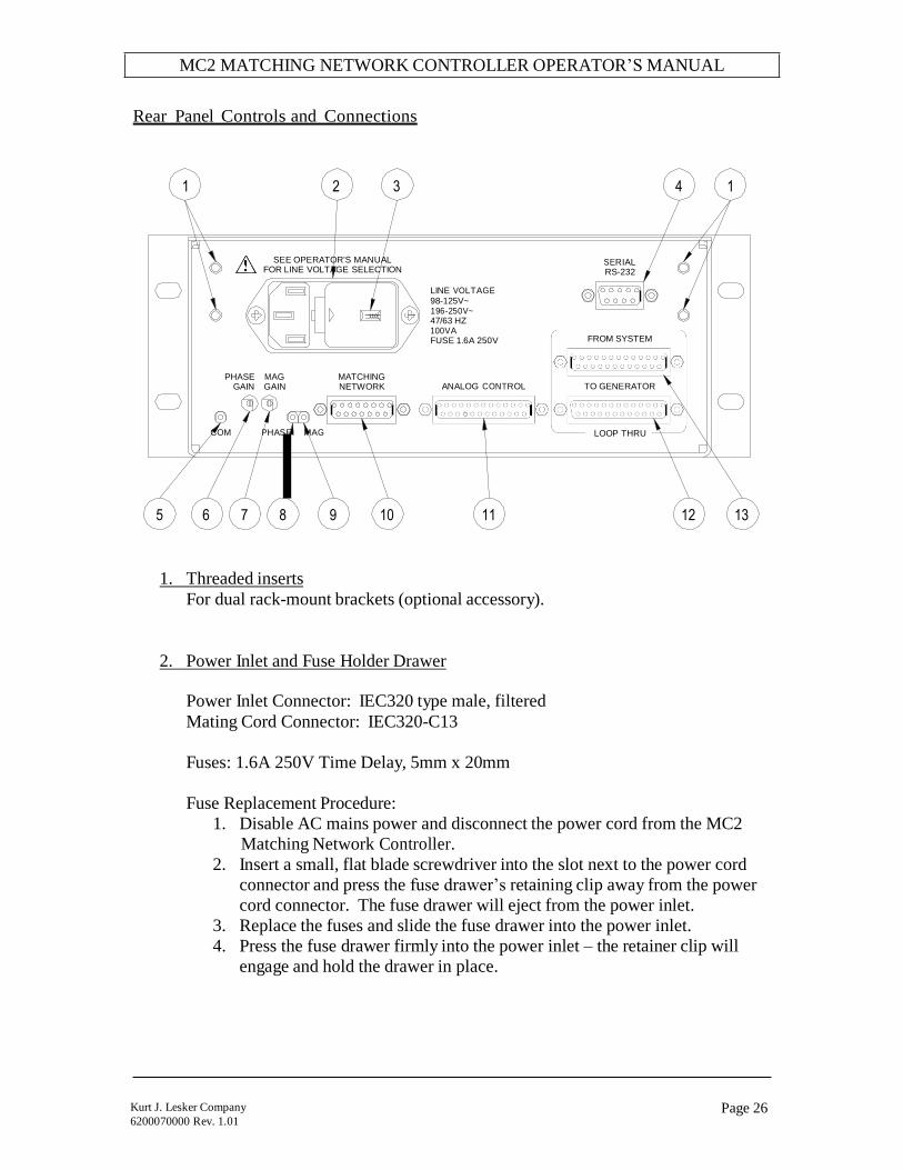
Rear Panel Controls and Connections
1 2 3 4 1
SEE OPERATOR'S MANUAL FOR LINE VOLTAGE SELECTION
SERIAL RS-232
110
LINE VOLTAGE 98-125V~
196-250V~ 47/63 HZ 100VA FUSE 1.6A 250V
FROM SYSTEM
PHASE MAG
GAIN GAIN MATCHING NETWORK
ANALOG CONTROL
TO GENERATOR
COM PHASE MAG LOOP THRU
5 6 7 8 9 10 11 12 13
1. Threaded inserts
For dual rack-mount brackets (optional accessory).
2. Power Inlet and Fuse Holder Drawer
Power Inlet Connector: IEC320 type male, filtered
Mating Cord Connector: IEC320-C13
Fuses: 1.6A 250V Time Delay, 5mm x 20mm
Fuse Replacement Procedure:
1. Disable AC mains power and disconnect the power cord from the MC2
Matching Network Controller.
2. Insert a small, flat blade screwdriver into the slot next to the power cord
connector and press the fuse drawer’s retaining clip away from the power
cord connector. The fuse drawer will eject from the power inlet.
3. Replace the fuses and slide the fuse drawer into the power inlet.
4. Press the fuse drawer firmly into the power inlet – the retainer clip will
engage and hold the drawer in place.
MC2 MATCHING NETWORK CONTROLLER OPERATOR’S MANUAL
Page 27 Kurt J. Lesker Company
6200070000 Rev. 1.01
3. Voltage Selector (part of Power Inlet)
CAUTION: UNLESS OTHERWISE SPECIFIED, THE MC2 CONTROLLER IS SHIPPED FROM THE FACTORY WITH THE LINE VOLTAGE SELECTOR SET FOR 110 VOLT OPERATION.
CHECK YOUR LINE VOLTAGE OR CONSULT A QUALIFIED ELECTRICIAN BEFORE CONNECTING THE MC2 CONTROLLER TO MAINS POWER. SELECTING THE WRONG LINE VOLTAGE MAY DAMAGE THE MC2
CONTROLLER AND VOID THE WARRANTY.
The MC2 Matching network controller has 2 mains voltage settings.
Use the “110” voltage setting for 100 to 125V 50/60 Hz AC Mains
Use the “220” voltage setting for 198 to 250V 50/60 Hz AC Mains
The mains voltage is displayed in the window in the fuse drawer.
AC Mains Voltage Change Procedure:
1. Disable AC mains power and disconnect the power cord from the MC2
Matching Network Controller.
2. Insert a small, flat blade screwdriver into the slot next to the power cord
connector and press the fuse drawer’s retaining clip away from the power
cord connector. The fuse drawer will eject from the power inlet. Set the
fuse drawer aside.
3. Remove the gray power selector from the power inlet housing
4. Rotate the power selector until the desired voltage is facing you.
5. Re-insert the voltage selector into the power inlet housing.
6. Place the fuse drawer back into the power inlet.
7. Press the fuse drawer firmly into the power inlet – the retainer clip will
engage and hold the drawer in place.
8. Connect the MC2 Matching Network Controller to the AC mains with a
power cord suitable for your location.
4. RS-232 Serial Interface Connector
Allows remote control and monitoring of the matching network and generator
parameters (monitoring of generator requires use of the FROM SYSTEM/TO
GENERATOR Loop-Thru connectors). Connector Type: 9 pin “D” female
For serial operation, see the Serial Commands section of this manual.
Pin Signal Description
1 No Connection No Connection
2 TXB Transmit Data
3 RXB Receive Data
MC2 MATCHING NETWORK CONTROLLER OPERATOR’S MANUAL
Page 28 Kurt J. Lesker Company
6200070000 Rev. 1.01
Pin Signal Description
4 No Connection No Connection
5 No Connection No Connection
6 No Connection No Connection
7 CTS Clear To Send
8 RTS Request To Send
9 No Connection No Connection
5. “COM” Test Point
Common return (negative) test point for the PHASE and MAG test points.
Internally connected to chassis ground. Used when making direct measurements
of Phase and Magnitude error signals during matching network set-up. Accepts
0.080” [2.03mm] diameter test probe.
6. PHASE Gain Adjustment
Adjusts the gain (sensitivity) of the Phase Error Amplifier. The Phase error
amplifier drives the matching network’s TUNE capacitor
7. MAG Gain Adjustment
Adjusts the gain (sensitivity) of the Magnitude Error Amplifier. The Magnitude
error amplifier drives the matching network’s LOAD capacitor
8. “PHASE” Test Point
PHASE error signal test point. Buffered PHASE detector output from the
matching network. Used when making direct measurements of the Phase error
signal and when nulling (calibrating) the matching network’s phase detector
during matching network set-up. See Troubleshooting instructions for details.
Accepts 0.080” [2.03mm] diameter test probe.
9. “MAG” Test Point
MAGnitude error signal test point. Buffered Magnitude detector output from the
matching network. Used when making direct measurements of the Magnitude
error signal and while nulling (calibrating) the matching network’s magnitude
detector during matching network set-up. See Troubleshooting instructions for
details. Accepts 0.080” [2.03mm] diameter test probe.
MC2 MATCHING NETWORK CONTROLLER OPERATOR’S MANUAL
Page 29 Kurt J. Lesker Company
6200070000 Rev. 1.01
10. Matching Network Connector
Control signals and motor drive for matching network. Connector Type: 15 pin
“D” female. Connect to the matching network’s “CONTROL” connector with a
shielded cable (purchased separately).
Pin Signal Description
1 TUNEMOTOR Drive voltage output for tune capacitor motor
–15VDC to +15VDC
2 GROUND Return for load capacitor motor. Internally
connected to chassis ground.
3 TUNEPOS Tune capacitor position feedback input. Analog
signal, 0.00VDC = minimum capacitance,
5.00VDC = maximum capacitance.
4 +5.25VREF Current limited +5.25VDC reference voltage output
for capacitor feedback signals. Do not connect
external equipment to this pin.
5 -0.25VREF Current limited -0.25VDC reference voltage output
for capacitor feedback signals. Do not connect
external equipment to this pin.
6 +12V Current limited +12VDC output for operation of
control circuits within the matching network. Do
not connect other equipment to this pin.
7 PHASE Phase (tune) error signal input. Analog input, -
10VDC to +10VDC range.
8 MAG Magnitude (load) error signal input. Analog input,
-10VDC to +10VDC range
9 LOADMOTOR Drive voltage output for load capacitor motor
–15VDC to +15VDC
10 GROUND Return for tune capacitor motor. Internally
connected to chassis ground.
11 LOADPOS Load capacitor position feedback input. Analog
signal, 0.00VDC = minimum capacitance,
5.00VDC = maximum capacitance.
12 GROUND Internally connected to chassis ground.
13 DC-PROBE DC Probe signal input. Analog, -10VDC to
+10VDC range
14 RF-PROBE DC Probe signal input. Analog, -10VDC to
+10VDC range
15 GROUND Internally connected to chassis ground.

MC2 MATCHING NETWORK CONTROLLER OPERATOR’S MANUAL
Page 30 Kurt J. Lesker Company
6200070000 Rev. 1.01
11. Analog Control Connector
Analog control signals for system interfacing. Connector Type: 25 pin “D”
female. Use shielded cable for making connections to system controller or
external equipment.
Pin Signal Description
1 No Connection No connection
2 PRELOAD Load capacitor preset enable input. TTL/HCMOS
compatible logic input, active high internally pulled
down to 0V. Apply a logic high signal to enable
preset, apply a logic low signal to disable preset.
3 PRELOAD-ON Load capacitor preset active output. TTL/HCMOS
compatible logic output, active low. Internally
pulled up to +5VDC. Logic low when controller is
presetting the load capacitor, logic high when the
load capacitor is not being pre-set.
4 PRETUNE-ON Tune capacitor preset active output. TTL/HCMOS
compatible logic output, active low. Internally pulled up to +5VDC. Logic low when controller is
presetting capacitors, logic high when the tune
capacitor is not being pre-set.
5 PRETUNE Tune capacitor preset enable input. TTL/HCMOS
compatible logic input, active high, internally
pulled down 0V. Apply a logic high signal to
enable preset, apply a logic low signal to disable
preset.
6 -TUNELIMIT Tune capacitor minimum limit signal output.
TTL/HCMOS compatible logic output, active high.
Output is a logic high when the tune capacitor has
reached its minimum limit. Output is a logic low
when the tune capacitor is not at its minimum limit.
7 +TUNELIMIT Tune capacitor maximum limit signal output.
TTL/HCMOS compatible logic output, active high.
Output is a logic high when the tune capacitor has
reached its maximum limit. Output is a logic low
when the tune capacitor is not at its maximum limit.
8 FAIL General purpose fail condition signal output.
TTL/HCMOS compatible logic output, active high.
Output state is a logic high if a fail condition is
detected (control cable disconnected or other
software-determined condition), output state is a
logic low if there is no fail condition.
MC2 MATCHING NETWORK CONTROLLER OPERATOR’S MANUAL
Page 31 Kurt J. Lesker Company
6200070000 Rev. 1.01
Pin Signal Description
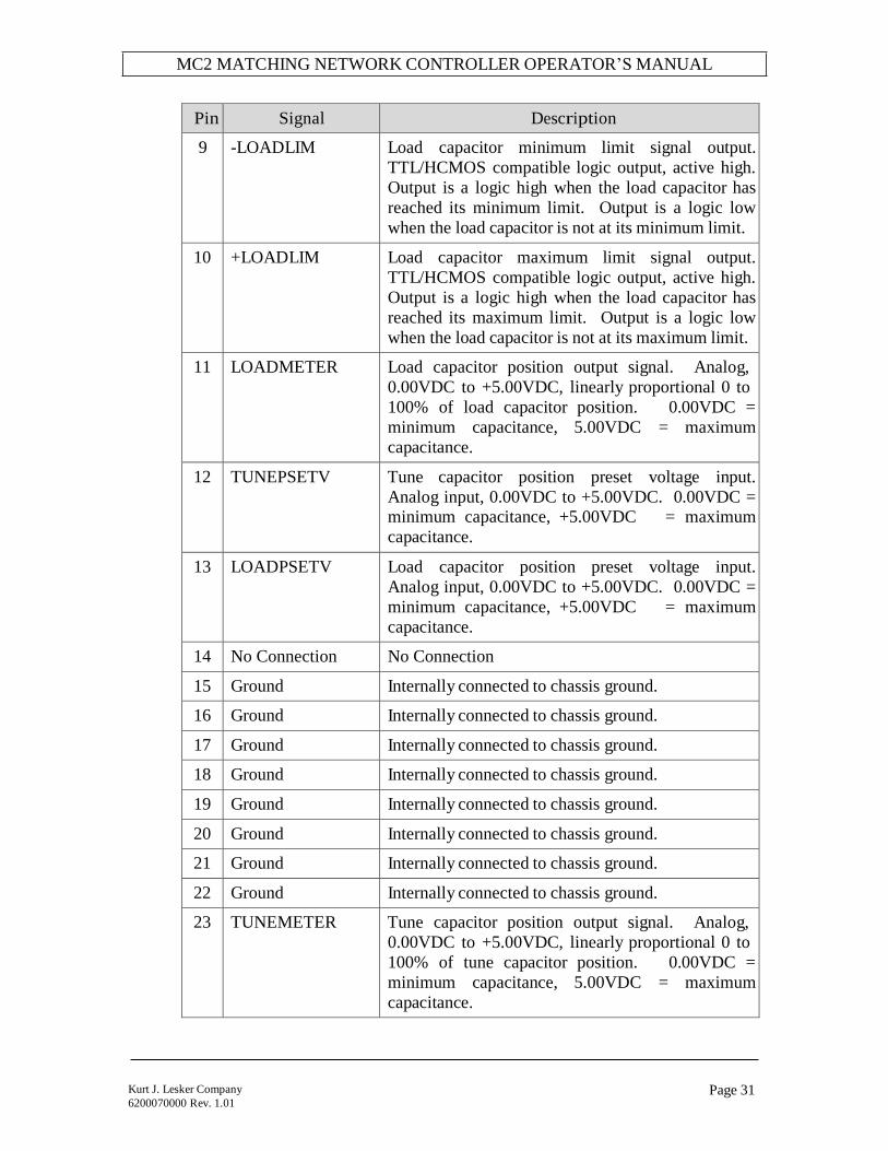
9 -LOADLIM Load capacitor minimum limit signal output.
TTL/HCMOS compatible logic output, active high.
Output is a logic high when the load capacitor has
reached its minimum limit. Output is a logic low
when the load capacitor is not at its minimum limit.
10 +LOADLIM Load capacitor maximum limit signal output.
TTL/HCMOS compatible logic output, active high.
Output is a logic high when the load capacitor has
reached its maximum limit. Output is a logic low
when the load capacitor is not at its maximum limit.
11 LOADMETER Load capacitor position output signal. Analog,
0.00VDC to +5.00VDC, linearly proportional 0 to
100% of load capacitor position. 0.00VDC =
minimum capacitance, 5.00VDC = maximum
capacitance.
12 TUNEPSETV Tune capacitor position preset voltage input.
Analog input, 0.00VDC to +5.00VDC. 0.00VDC = minimum capacitance, +5.00VDC = maximum
capacitance.
13 LOADPSETV Load capacitor position preset voltage input.
Analog input, 0.00VDC to +5.00VDC. 0.00VDC =
minimum capacitance, +5.00VDC = maximum
capacitance.
14 No Connection No Connection
15 Ground Internally connected to chassis ground.
16 Ground Internally connected to chassis ground.
17 Ground Internally connected to chassis ground.
18 Ground Internally connected to chassis ground.
19 Ground Internally connected to chassis ground.
20 Ground Internally connected to chassis ground.
21 Ground Internally connected to chassis ground.
22 Ground Internally connected to chassis ground.
23 TUNEMETER Tune capacitor position output signal. Analog,
0.00VDC to +5.00VDC, linearly proportional 0 to
100% of tune capacitor position. 0.00VDC =
minimum capacitance, 5.00VDC = maximum
capacitance.

MC2 MATCHING NETWORK CONTROLLER OPERATOR’S MANUAL
Page 32 Kurt J. Lesker Company
6200070000 Rev. 1.01
Pin Signal Description
24 Ground Internally connected to chassis ground.
25 Ground Internally connected to chassis ground.
12 and 13: Loop-Thru Connectors
These connectors are provided to interface the MC2 matching network controller
with an RF generator. This enables the MC2 to monitor and display the
generator’s setpoint, forward power, and reflected power, and supply the RF or
DC probe voltage signal to the RF generator (for voltage control). All other
control signals are passed from the “FROM SYSTEM” connector to the “TO
GENERATOR” connector without modification.
The Loop-Thru connectors are designed to be plug-compatible with the KJLC
R/L20XX/30XX/50XX series of RF generators. Other RF generators can be
connected with external cabling - contact KJLC customer service department for
assistance.
12. “TO GENERATOR” Connector:
Connects to the RF Generator’s analog interface or control connector.
Connector type: 25 pin “D” female. Use shielded cable to make connections
to the RF Generator.
Pin Signal Description
1 Loop-Thru Connected to pin 1 of SYSTEM connector
2 Loop-Thru Connected to pin 2 of SYSTEM connector
3 RFON1 RFON signal output. TTL/HCMOS compatible
logic output, active low. The logic state is the
same as the pin 3 of the SYSTEM connector
4 Loop-Thru Connected to pin 4 of SYSTEM connector
5 Loop-Thru Connected to pin 5 of SYSTEM connector
6 Loop-Thru Connected to pin 6 of SYSTEM connector
7 Loop-Thru Connected to pin 7 of SYSTEM connector
8 Loop-Thru Connected to pin 8 of SYSTEM connector
9 Loop-Thru Connected to pin 9 of SYSTEM connector
10 FORWARD Forward Power monitor signal. Analog loop-
thru, 0.00VDC to +5.00VDC. Connected to pin
10 of SYSTEM connector.
11 REFLECTED Reflected Power monitor signal. Analog loop-
thru, 0.00VDC to +5.00VDC. Connected to pin

MC2 MATCHING NETWORK CONTROLLER OPERATOR’S MANUAL
Page 33 Kurt J. Lesker Company
6200070000 Rev. 1.01
Pin Signal Description
11 of SYSTEM connector.
12 PROBE RF or DC probe signal (from matching network
controller, derived from the matching network).
Analog, -10VDC to +10VDC. Connected to pin
12 of SYSTEM connector.
13 SETPOINT Forward Power Setpoint signal. Analog loop-
thru, -10VDC to +10VDC, single-ended.
Connected to pin 13 of SYSTEM connector.
14 Loop-Thru Connected to pin 14 of SYSTEM connector.
15 GROUND Internally connected to chassis ground.
16 GROUND Internally connected to chassis ground.
17 GROUND Internally connected to chassis ground.
18 GROUND Internally connected to chassis ground.
19 Loop-Thru Connected to pin 19 of SYSTEM connector.
20 Loop-Thru Connected to pin 20 of SYSTEM connector.
21 Loop-Thru Connected to pin 21 of SYSTEM connector.
22 FWDRET Forward Power Monitor return signal. Internally
connected to chassis ground.
23 REFRET Reflected Power Monitor return signal. Internally
connected to chassis ground.
24 FBRET External Feedback (Probe) return signal.
Internally connected to chassis ground.
25 SETRET Forward Power Setpoint return signal. Internally
connected to chassis ground.
Note: KJLC RF generators use a differential
setpoint input. To prevent erratic operation, this
signal must be connected to the generator’s
setpoint return terminal.
.

MC2 MATCHING NETWORK CONTROLLER OPERATOR’S MANUAL
Page 34 Kurt J. Lesker Company
6200070000 Rev. 1.01
13. “FROM SYSTEM” Connector
Connects to the user’s system controller or external equipment. Connector
type: 25 pin “D” male. Use shielded cable to make connections to system
controller or external equipment.
Pin Signal Description
1 Loop-Thru Connected to pin 1 of GENERATOR connector
2 Loop-Thru Connected to pin 2 of GENERATOR connector
3 RFON RFON signal input. TTL/HCMOS compatible
logic input, active low. Internally pulled up to
+5VDC.
4 Loop-Thru Connected to pin 4 of GENERATOR connector
5 Loop-Thru Connected to pin 5 of GENERATOR connector
6 Loop-Thru Connected to pin 6 of GENERATOR connector
7 Loop-Thru Connected to pin 7 of GENERATOR connector
8 Loop-Thru Connected to pin 8 of GENERATOR connector
9 Loop-Thru Connected to pin 9 of GENERATOR connector
10 FORWARD Forward Power monitor signal. Analog loop- thru, 0.00VDC to +5.00VDC. Connected to pin
10 of GENERATOR connector.
11 REFLECTED Reflected Power monitor signal. Analog loop-
thru, 0.00VDC to +5.00VDC. Connected to pin
11 of GENERATOR connector.
12 PROBE RF or DC probe signal (from matching network
controller). Analog, -10VDC to +10VDC.
Connected to pin 12 of GENERATOR connector.
13 SETPOINT Forward Power Setpoint signal. Analog loop-
thru, -10VDC to +10VDC, single-ended.
Connected to pin 13 of GENERATOR connector.
14 Loop-Thru Connected to pin 14 of GENERATOR connector.
15 GROUND Internally connected to chassis ground.
16 GROUND Internally connected to chassis ground.
17 GROUND Internally connected to chassis ground.
18 GROUND Internally connected to chassis ground.
19 Loop-Thru Connected to pin 19 of GENERATOR connector.
20 Loop-Thru Connected to pin 20 of GENERATOR connector.

MC2 MATCHING NETWORK CONTROLLER OPERATOR’S MANUAL
Page 35 Kurt J. Lesker Company
6200070000 Rev. 1.01
Pin Signal Description
21 Loop-Thru Connected to pin 21 of GENERATOR connector.
22 FWDRET Forward Power Monitor return signal. Internally
connected to chassis ground.
23 REFRET Reflected Power Monitor return signal. Internally
connected to chassis ground.
24 FBRET External Feedback (Probe) return signal.
Internally connected to chassis ground.
25 SETRET Forward Power Setpoint return signal. Internally
connected to chassis ground.
MC2 MATCHING NETWORK CONTROLLER OPERATOR’S MANUAL
Page 36 Kurt J. Lesker Company
6200070000 Rev. 1.01
TYPICAL INTERFACE CONNECTIONS
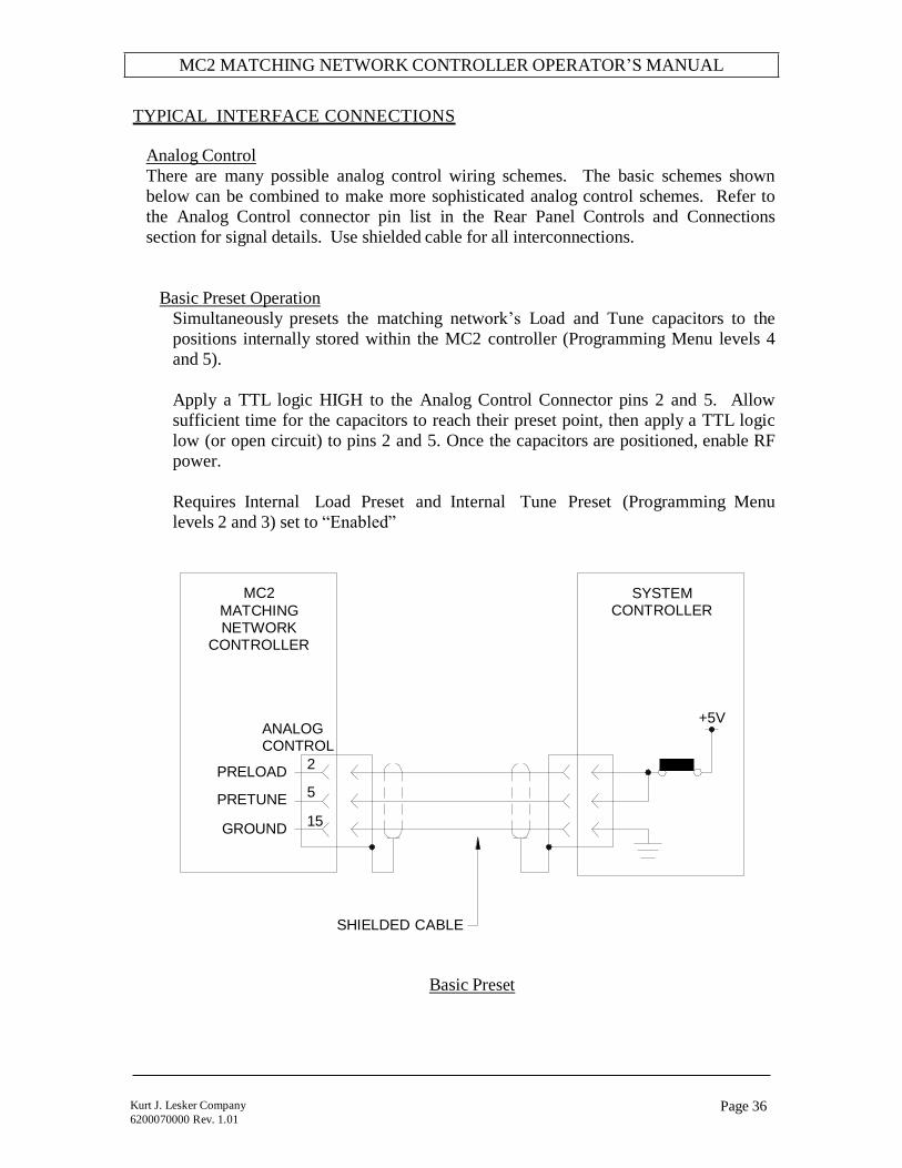
Analog Control
There are many possible analog control wiring schemes. The basic schemes shown
below can be combined to make more sophisticated analog control schemes. Refer to
the Analog Control connector pin list in the Rear Panel Controls and Connections
section for signal details. Use shielded cable for all interconnections.
Basic Preset Operation
Simultaneously presets the matching network’s Load and Tune capacitors to the
positions internally stored within the MC2 controller (Programming Menu levels 4
and 5).
Apply a TTL logic HIGH to the Analog Control Connector pins 2 and 5. Allow
sufficient time for the capacitors to reach their preset point, then apply a TTL logic
low (or open circuit) to pins 2 and 5. Once the capacitors are positioned, enable RF
power.
Requires Internal Load Preset and Internal Tune Preset (Programming Menu
levels 2 and 3) set to “Enabled”
MC2
MATCHING NETWORK
CONTROLLER
ANALOG CONTROL
SYSTEM CONTROLLER
+5V
PRELOAD 2
PRETUNE 5
GROUND 15
SHIELDED CABLE
Basic Preset
MC2 MATCHING NETWORK CONTROLLER OPERATOR’S MANUAL
Page 37 Kurt J. Lesker Company
6200070000 Rev. 1.01
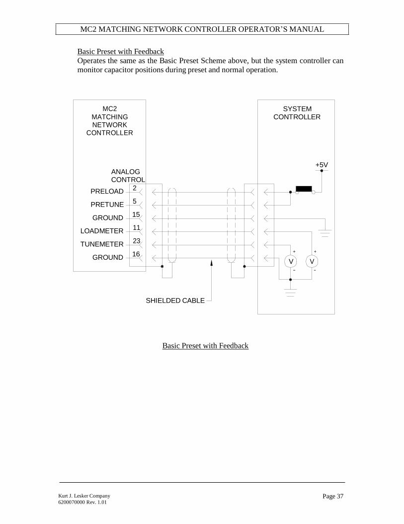
Basic Preset with Feedback
Operates the same as the Basic Preset Scheme above, but the system controller can
monitor capacitor positions during preset and normal operation.
MC2
MATCHING NETWORK
CONTROLLER
SYSTEM CONTROLLER
ANALOG CONTROL
+5V
PRELOAD 2
PRETUNE 5
GROUND 15
LOADMETER 11
TUNEMETER 23
GROUND 16
+ +
V V -- --
SHIELDED CABLE
Basic Preset with Feedback

MC2 MATCHING NETWORK CONTROLLER OPERATOR’S MANUAL
Page 38 Kurt J. Lesker Company
6200070000 Rev. 1.01
External Preset Operation
Simultaneously presets the matching network’s Load and Tune capacitors to the
positions requested by the system controller.
Apply a TTL logic HIGH to the Analog Control Connector pins 2 and 5. Allow
sufficient time for the capacitors to reach their preset point, or monitor the capacitor
position signals TUNEMETER and LOADMETER until the capacitors to reach
their requested positions, then apply a TTL logic level LOW (or open circuit) to
pins 2 and 5. Once the capacitors are positioned, enable RF power.
Requires Internal Load Preset and Internal Tune Preset (Programming Menu
levels 2 and 3) set to “Disabled”
MC2
MATCHING
NETWORK CONTROLLER
SYSTEM
CONTROLLER
+5V
ANALOG CONTROL
TUNEPSETV 12
LOADPSETV 13
GROUND 17
PRELOAD 2
PRETUNE 5
GROUND 15
LOADMETER 11
TUNEMETER 23
+ +
GROUND 16
SHIELDED CABLE
V V
-- --
External Preset

MC2 MATCHING NETWORK CONTROLLER OPERATOR’S MANUAL
Page 39 Kurt J. Lesker Company
6200070000 Rev. 1.01
Full Analog Control
The system controller can individually preset the matching network’s Load and
Tune capacitors, monitor the capacitor positions and monitor all status signals.
Make connections to the Analog Control Connector as shown below. Apply preset
voltages to pins 12 and 13 and apply a TTL logic HIGH state to pin 2 and/or pin 5.
Allow sufficient time for the capacitors to reach their preset point, or monitor the
capacitor position signals TUNEMETER (pin23) and LOADMETER (pin 11) until
the capacitors to reach their requested positions, then apply a TTL logic LOW
signal to pins 2 and 5. Once the capacitors are positioned, enable RF power.
Requires Internal Load Preset and Internal Tune Preset (Programming Menu
levels 2 and 3) set to “Disabled”
MC2
MATCHING NETWORK
CONTROLLER
ANALOG CONTROL
PRELOAD-ON 3
PRETUNE-ON 4
-TUNELIMIT 6
+TUNELIMIT 7
FAIL 8
SYSTEM CONTROLLER
-LOADLIM 9
+LOADLIM 10
GROUND 18
TUNEPSETV 12
LOADPSETV 13
GROUND 17
PRELOAD 2
PRETUNE 5
GROUND 15
GROUND 16
LOADMETER 11
GROUND 19
+5V
TUNEMETER 23
SHIELDED CABLE
Full Analog Control

MC2 MATCHING NETWORK CONTROLLER OPERATOR’S MANUAL
Page 40 Kurt J. Lesker Company
6200070000 Rev. 1.01
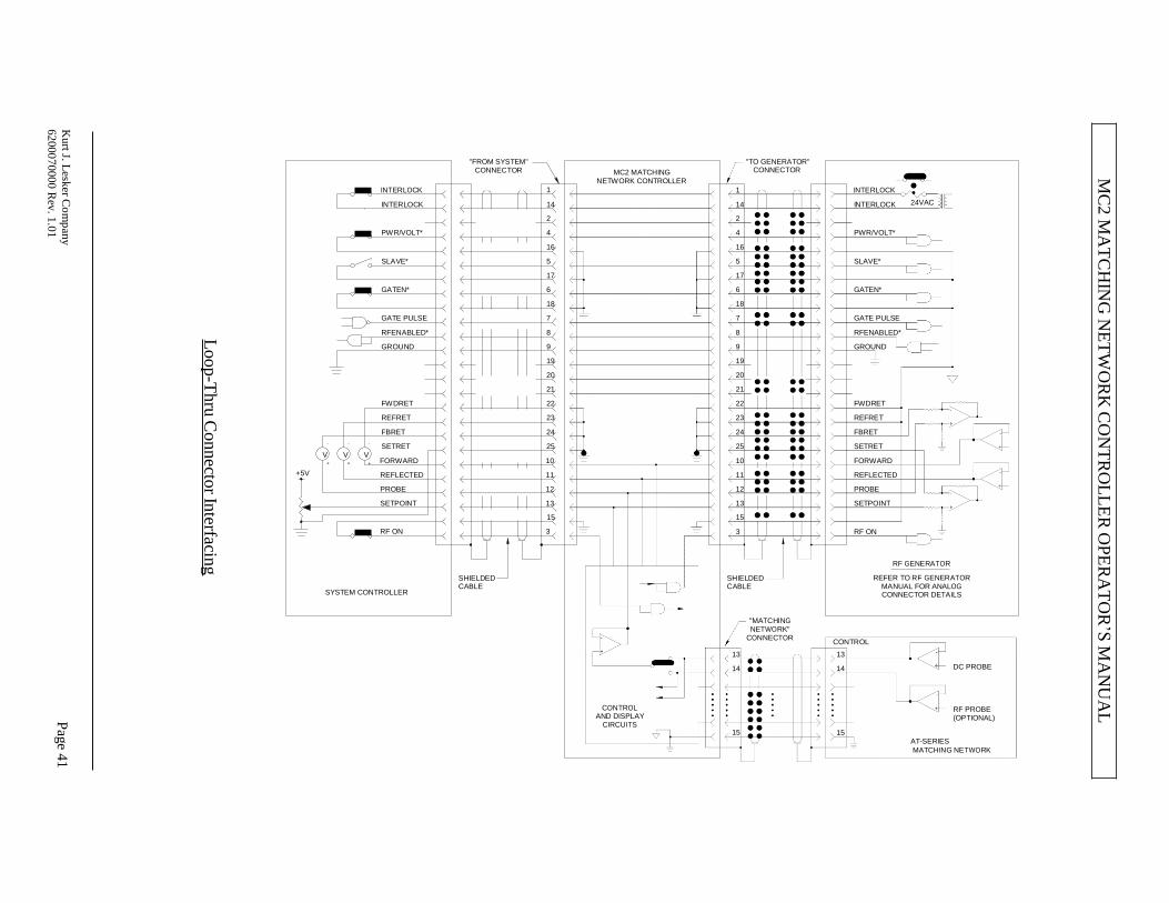
Loop Thru Connector Interfacing
The rear panel Loop-Thru connectors interface the MC2 Matching Network
Controller to an RF Generator and your system controller. Using the Loop-Thru
connectors can simplify system wiring when using RF or DC Voltage control modes.
The configuration diagrammed below allows the MC2 Matching Network Controller
to monitor and display the RF Generator’s setpoint, forward power, and reflected
power and supply the AT-Series Matching Network’s RF or DC probe voltage signal
to the RF generator for voltage control operation.
All other control signals are passed from the “FROM SYSTEM” connector to the
“TO GENERATOR” connector without modification.
The RF Generator analog connections shown below are generic. The actual analog
interface connection wiring depends on the RF Generator model. Consult the RF
Generator’s instruction manual for appropriate analog connector pin-outs or contact a
customer service representative for wiring assistance and available interface cables.
MC2 Controller Programming Notes:
1. Set the RFON Signal polarity (Programming Menu, level 20) to match the RF
Generator’s RFON signal polarity.
2. Select the desired Voltage Probe (Programming Menu, level 6)
3. Set the Voltage Probe’s attenuation factor (Programming Menu, levels 7 and 8)
4. Set the Forward and Reflected Power full-scale wattage (Programming Menu,
levels 13 and 14) to match the RF Generator’s scaling.
5. Set the FWD/REF DISPLAY (Programming Menu, level 11) to “ON”.
6. Set the RF/DCV DISPLAY (Programming Menu, level 12) to “ON”.
System Wiring Notes:
1. Use shielded cables for all interface wiring. Foil shielded cable with a drain
wire is recommended.
2. Use connectors with metal shells and connect the cable shield (drain wire) to the
connector’s shell.
MC
2 M
AT
CH
ING
NE
TW
OR
K C
ON
TR
OL
LE
R O
PE
RA
TO
R’S
MA
NU
AL
Loop-T
hru
Connecto
r Interfacin
g
Pag
e 41
K
urt J. L
esker C
om
pan
y
62000
7000
0 R
ev. 1
.01
INTERLOCK
"FROM SYSTEM" CONNECTOR
1
"TO GENERATOR"
MC2 MATCHING CONNECTOR NETWORK CONTROLLER
1 INTERLOCK
- - -
V V V
INTERLOCK 14
2
PWR/VOLT* 4
16
SLAVE* 5
17
GATEN* 6
18
GATE PULSE 7
RFENABLED* 8
GROUND 9
19
20
21
FWDRET 22
REFRET 23
FBRET 24
SETRET 25
14 INTERLOCK
2
4 PWR/VOLT*
16
5 SLAVE*
17
6 GATEN*
18
7 GATE PULSE
8 RFENABLED*
9 GROUND
19
20
21
22 FWDRET
23 REFRET
24 FBRET
25 SETRET
24VAC
+ +
+5V
+ FORWARD 10
REFLECTED 11
PROBE 12
SETPOINT 13
15
RF ON 3
10 FORWARD
11 REFLECTED
12 PROBE
13 SETPOINT
15
3 RF ON
SYSTEM CONTROLLER
SHIELDED CABLE
SHIELDED CABLE
RF GENERATOR
REFER TO RF GENERATOR MANUAL FOR ANALOG CONNECTOR DETAILS
"MATCHING NETWORK"
CONNECTOR
13
14
CONTROL AND DISPLAY
CIRCUITS 15
CONTROL
13
14
15
AT-SERIES
DC PROBE
RF PROBE (OPTIONAL)
MATCHING NETWORK

Page 42 Kurt J. Lesker Company
6200070000 Rev. 1.01
Typical Configurations Popular configurations are depicted in this manual. Other configurations and wiring schemes are possible. For assistance with system wiring schemes, contact the customer
service department or a KJLC customer service depot. Coaxial cables, control
cables, matching networks, RF generators, and system equipment are not supplied
with the MC2 Controller.
1. Basic Configuration
The basic configuration consists of the MC2 Controller, an AT-Series matching
network, an RF Power source (generator), and a load. There are no control
connections between the MC2 controller and the RF Power source and
load/processing system. In this configuration, the MC2 and matching network
operate independently from the RF power source and load/processing system.
PLASMA CHAMBER OR OTHER LOAD
EQUIPOTENTIAL BONDING TERMINAL
MC2
AT-SERIES CONTROL CABLE
COAXIAL CABLE(S) OR DIRECT INTERNAL CONNECTION
RF OUTPUT
CONTROLLER
MATCHING NETWORK
CONTROL
AT-SERIES MATCHING NETWORK
MAINS POWER
EQUIPOTENTIAL BONDING TERMINAL
RF
INPUT
COAXIAL CABLE
MAINS POWER
EQUIPOTENTIAL BONDING TERMINAL
RF GENERATOR
RF
OUTPUT
Basic Configuration

Page 43 Kurt J. Lesker Company
6200070000 Rev. 1.01
2. Basic Analog System
The Basic Analog System configuration consists of the MC2 Controller, an AT-
Series matching network, and RF Power source (generator), system controller and a
load. The system controller interfaces to the MC2 matching network controller and
the RF generator. There are no control connections between the MC2 controller
and the RF Power source.
In this configuration, the MC2 and matching network operate independently from
the RF power source. The system controller controls the operation of the MC2
controller and the RF generator. Voltage control (a DC Probe or RF Probe within
the matching network provides a feedback signal to the generator’s power
regulation circuits) of the RF generator is not available.
SYSTEM CONTROLLER
PLASMA CHAMBER OR OTHER LOAD
EQUIPOTENTIAL BONDING TERMINAL
TO MATCH CONTROL
TO
GENERATOR
SHIELDED CABLES
COAXIAL CABLE(S)
OR DIRECT INTERNAL CONNECTION
ANALOG
CONTROL
RF OUTPUT
MC2 MATCHING
CONTROL AT-SERIES
CONTROLLER NETWORK
AT-SERIES
CONTROL EQUIPOTENTIAL
MATCHING
NETWORK
RF
CABLE
MAINS POWER
BONDING TERMINAL INPUT
COAXIAL CABLE
EQUIPOTENTIAL BONDING TERMINAL
RF
OUTPUT
ANALOG INTERFACE
RF GENERATOR
MAINS POWER
Basic Analog System Configuration

Page 44 Kurt J. Lesker Company
6200070000 Rev. 1.01
3. Full Analog System
The Full Analog System configuration consists of the MC2 Controller, an AT-
Series matching network, and RF Power source (generator), system controller and a
load. The system controller interfaces to the MC2 matching network controller and
the RF generator with shielded analog control cables.
In this configuration, the MC2 and matching network operate independently from
the RF power source. The system controller controls the operation of the MC2
controller and the RF generator. A voltage control signal (a DC Probe or RF Probe
within the matching network provides a feedback signal to the generator’s power
regulation circuits) from the matching network is routed through the MC2 controller
to the RF generator.
The system controller controls RF enable/disable and other functions of the RF
generator.
SYSTEM PLASMA CHAMBER
CONTROLLER OR OTHER LOAD
EQUIPOTENTIAL BONDING TERMINAL
TO MATCH CONTROL
TO
GENERATOR
COAXIAL CABLE(S)
OR DIRECT INTERNAL
CONNECTION
ANALOG CONTROL
FROM
SYSTEM
EQUIPOTENTIAL BONDING TERMINAL
RF OUTPUT
MC2 MATCHING
CONTROL
AT-SERIES
MATCHING
NETWORK CONTROLLER NETWORK
TO
GENERATOR
AT-SERIES
CONTROL
CABLE
RF INPUT
MAINS POWER
COAXIAL CABLE
EQUIPOTENTIAL BONDING TERMINAL
RF
OUTPUT
ANALOG RF GENERATOR
INTERFACE
MAINS
POWER
Full Analog System
Page 45 Kurt J. Lesker Company
6200070000 Rev. 1.01
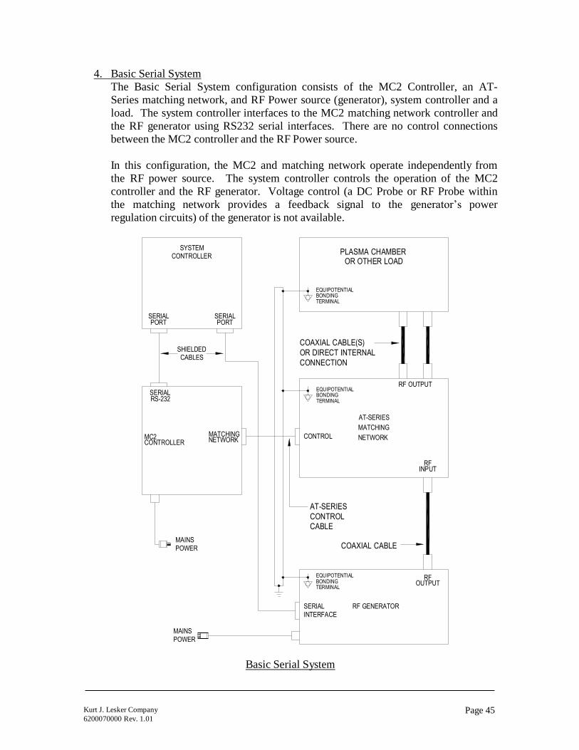
4. Basic Serial System
The Basic Serial System configuration consists of the MC2 Controller, an AT-
Series matching network, and RF Power source (generator), system controller and a
load. The system controller interfaces to the MC2 matching network controller and
the RF generator using RS232 serial interfaces. There are no control connections
between the MC2 controller and the RF Power source.
In this configuration, the MC2 and matching network operate independently from
the RF power source. The system controller controls the operation of the MC2
controller and the RF generator. Voltage control (a DC Probe or RF Probe within
the matching network provides a feedback signal to the generator’s power
regulation circuits) of the generator is not available.
SYSTEM PLASMA CHAMBER
CONTROLLER OR OTHER LOAD
EQUIPOTENTIAL BONDING TERMINAL
SERIAL PORT
SERIAL PORT
SHIELDED CABLES
COAXIAL CABLE(S)
OR DIRECT INTERNAL
CONNECTION
SERIAL RS-232
EQUIPOTENTIAL BONDING TERMINAL
RF OUTPUT
MC2 CONTROLLER
MATCHING NETWORK
CONTROL
AT-SERIES
MATCHING
NETWORK
RF
INPUT
MAINS POWER
AT-SERIES
CONTROL CABLE
COAXIAL CABLE
EQUIPOTENTIAL BONDING TERMINAL
RF
OUTPUT
SERIAL INTERFACE
RF GENERATOR
MAINS POWER
Basic Serial System

Page 46 Kurt J. Lesker Company
6200070000 Rev. 1.01
5. Serial System With Voltage Control
The Serial System with Voltage Control consists of the MC2 Controller, an AT-
Series matching network, and RF Power source (generator), system controller and a
load. The system controller interfaces to the MC2 matching network controller and
the RF generator using RS232 serial interfaces. The MC2 routes the DC Probe
signal (feedback signal) to the RF Power source.
In this configuration, the MC2 and matching network operate independently from
the RF power source. The system controller controls the operation of the MC2
controller and the RF generator. Voltage control (a DC Probe or RF Probe within
the matching network provides a feedback signal to the generator’s power
regulation circuits) of the generator is available.
SYSTEM
CONTROLLER
PLASMA CHAMBER OR OTHER LOAD
EQUIPOTENTIAL BONDING TERMINAL
SERIAL PORT
SERIAL PORT
SHIELDED
CABLES
COAXIAL CABLE(S) OR DIRECT INTERNAL CONNECTION
SERIAL RS-232
EQUIPOTENTIAL BONDING TERMINAL
RF OUTPUT
MC2 CONTROLLER
MATCHING NETWORK
CONTROL
AT-SERIES
MATCHING
NETWORK
MAINS
POWER
TO
GENERATOR
AT-SERIES CONTROL CABLE
COAXIAL CABLE
RF INPUT
EQUIPOTENTIAL BONDING TERMINAL
SERIAL
RF
OUTPUT
MAINS
POWER
INTERFACE ANALOG INTERFACE
RF GENERATOR
Serial System with Voltage Control

Page 47 Kurt J. Lesker Company
6200070000 Rev. 1.01
6. Fully Configured System
The Fully Configured System consists of the MC2 Controller, an AT-Series
matching network, and RF Power source (generator), system controller and a load.
The system controller interfaces to the MC2 matching network controller and the
RF generator using RS232 Serial and Analog Control interfaces. The MC2 routes
the DC Probe signal (feedback signal) to the RF Power source.
In this configuration, the MC2 and matching network operate independently from
the RF power source. The system controller controls the operation of the MC2
controller and the RF generator. Voltage control (a DC Probe or RF Probe within
the matching network provides a feedback signal to the generator’s power
regulation circuits) of the generator is available.
The system controller controls RF enable/disable and other functions of the RF
generator.
SYSTEM PLASMA CHAMBER
CONTROLLER OR OTHER LOAD
EQUIPOTENTIAL BONDING TERMINAL
SERIAL
TO MATCH
TO SERIAL
PORT CONTROL GENERATOR PORT
COAXIAL CABLE(S) OR DIRECT INTERNAL
CONNECTION
SERIAL RS-232
ANALOG
CONTROL
FROM
SYSTEM
EQUIPOTENTIAL BONDING TERMINAL
RF OUTPUT
MC2 CONTROLLER
MATCHING NETWORK
CONTROL
AT-SERIES
MATCHING
NETWORK
MAINS
POWER
TO
GENERATOR
AT-SERIES
CONTROL CABLE
COAXIAL CABLE
RF INPUT
EQUIPOTENTIAL BONDING TERMINAL
SERIAL
RF
OUTPUT
MAINS
POWER
INTERFACE ANALOG INTERFACE
RF GENERATOR
Fully Configured System

Page 48 Kurt J. Lesker Company
6200070000 Rev. 1.01
!
Maintenance
The MC2 Automatic Matching Network Controller is designed to be maintenance free.
There are no user maintainable assemblies inside the unit. The MC2 is designed for use
in a clean environment. Periodically check the air vents for accumulation of dust and
debris. Clean the air vents with a vacuum cleaner if they appear dirty or clogged.
Restricting the air vents or installing the MC2 Automatic Matching
Network Controller in a dusty environment may impact the long-
term reliability of the matching network controller.
Cleaning:
DO NOT clean the MC2 Automatic Matching Network Controller when RF power is
applied to the matching network or when the unit is connected to the AC mains. The
exterior of the matching network controller may be cleaned with a soft cloth,
dampened with soap and water or a mild solvent, such as alcohol.
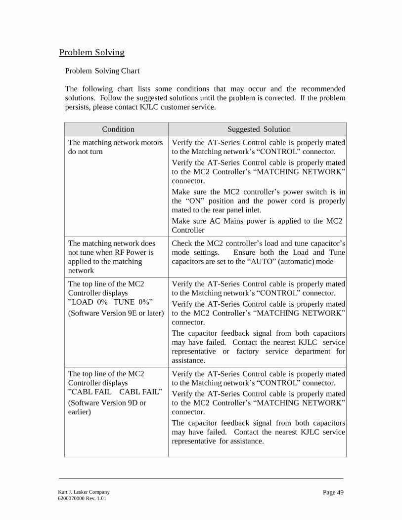
Page 49 Kurt J. Lesker Company
6200070000 Rev. 1.01
Problem Solving
Problem Solving Chart
The following chart lists some conditions that may occur and the recommended
solutions. Follow the suggested solutions until the problem is corrected. If the problem
persists, please contact KJLC customer service.
Condition Suggested Solution
The matching network motors
do not turn
Verify the AT-Series Control cable is properly mated
to the Matching network’s “CONTROL” connector.
Verify the AT-Series Control cable is properly mated
to the MC2 Controller’s “MATCHING NETWORK”
connector.
Make sure the MC2 controller’s power switch is in
the “ON” position and the power cord is properly
mated to the rear panel inlet.
Make sure AC Mains power is applied to the MC2
Controller
The matching network does
not tune when RF Power is
applied to the matching
network
Check the MC2 controller’s load and tune capacitor’s
mode settings. Ensure both the Load and Tune
capacitors are set to the “AUTO” (automatic) mode
The top line of the MC2
Controller displays
”LOAD 0% TUNE 0%”
(Software Version 9E or later)
Verify the AT-Series Control cable is properly mated
to the Matching network’s “CONTROL” connector.
Verify the AT-Series Control cable is properly mated
to the MC2 Controller’s “MATCHING NETWORK”
connector.
The capacitor feedback signal from both capacitors
may have failed. Contact the nearest KJLC service
representative or factory service department for
assistance.
The top line of the MC2
Controller displays ”CABL FAIL CABL FAIL”
(Software Version 9D or
earlier)
Verify the AT-Series Control cable is properly mated to the Matching network’s “CONTROL” connector.
Verify the AT-Series Control cable is properly mated
to the MC2 Controller’s “MATCHING NETWORK”
connector.
The capacitor feedback signal from both capacitors
may have failed. Contact the nearest KJLC service
representative for assistance.
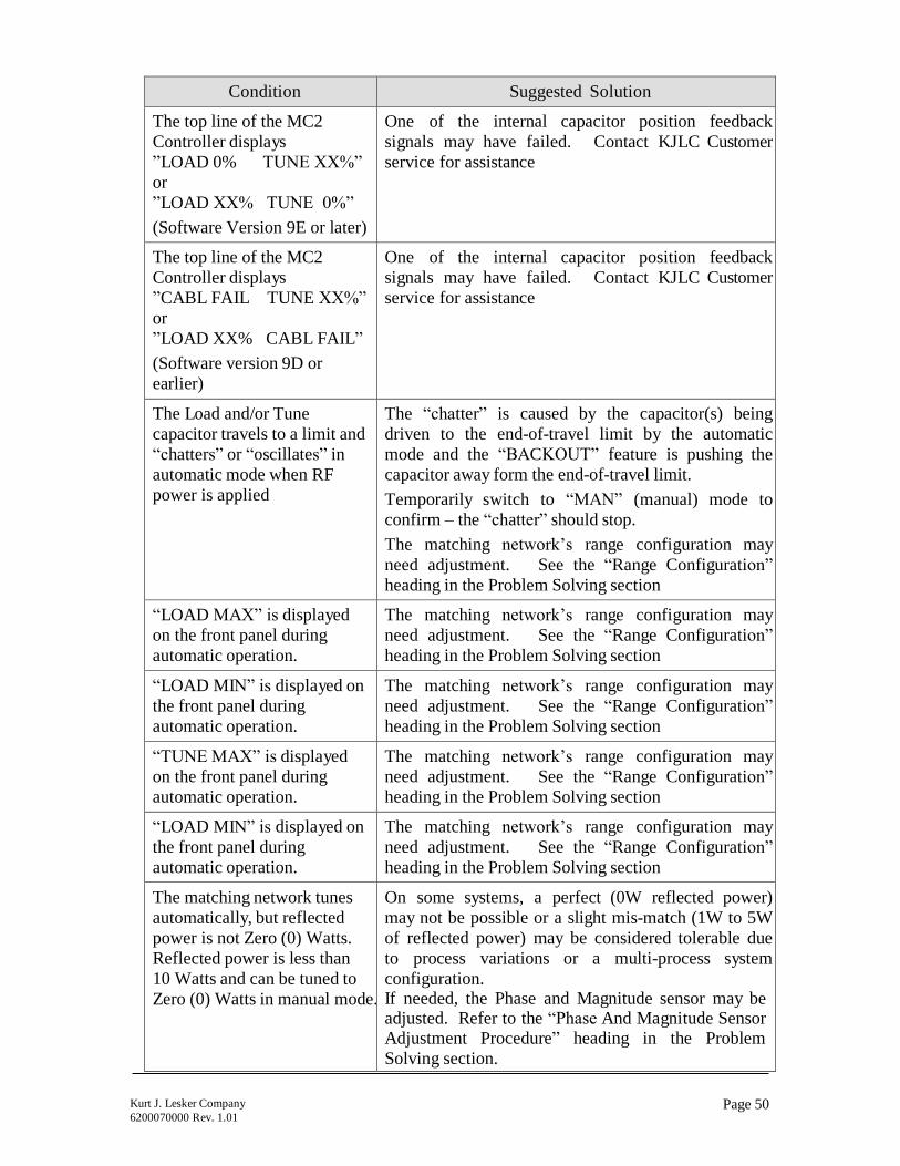
Page 50 Kurt J. Lesker Company
6200070000 Rev. 1.01
Condition Suggested Solution
The top line of the MC2
Controller displays
”LOAD 0% TUNE XX%”
or
”LOAD XX% TUNE 0%”
(Software Version 9E or later)
One of the internal capacitor position feedback
signals may have failed. Contact KJLC Customer
service for assistance
The top line of the MC2
Controller displays
”CABL FAIL TUNE XX%”
or
”LOAD XX% CABL FAIL”
(Software version 9D or
earlier)
One of the internal capacitor position feedback
signals may have failed. Contact KJLC Customer
service for assistance
The Load and/or Tune
capacitor travels to a limit and
“chatters” or “oscillates” in
automatic mode when RF
power is applied
The “chatter” is caused by the capacitor(s) being
driven to the end-of-travel limit by the automatic
mode and the “BACKOUT” feature is pushing the
capacitor away form the end-of-travel limit.
Temporarily switch to “MAN” (manual) mode to
confirm – the “chatter” should stop.
The matching network’s range configuration may
need adjustment. See the “Range Configuration”
heading in the Problem Solving section
“LOAD MAX” is displayed
on the front panel during
automatic operation.
The matching network’s range configuration may
need adjustment. See the “Range Configuration”
heading in the Problem Solving section
“LOAD MIN” is displayed on
the front panel during
automatic operation.
The matching network’s range configuration may
need adjustment. See the “Range Configuration”
heading in the Problem Solving section
“TUNE MAX” is displayed
on the front panel during
automatic operation.
The matching network’s range configuration may
need adjustment. See the “Range Configuration”
heading in the Problem Solving section
“LOAD MIN” is displayed on
the front panel during
automatic operation.
The matching network’s range configuration may
need adjustment. See the “Range Configuration”
heading in the Problem Solving section
The matching network tunes
automatically, but reflected
power is not Zero (0) Watts.
Reflected power is less than
10 Watts and can be tuned to
Zero (0) Watts in manual mode.
On some systems, a perfect (0W reflected power)
may not be possible or a slight mis-match (1W to 5W
of reflected power) may be considered tolerable due
to process variations or a multi-process system
configuration. If needed, the Phase and Magnitude sensor may be adjusted. Refer to the “Phase And Magnitude Sensor Adjustment Procedure” heading in the Problem
Solving section.
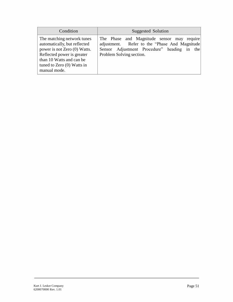
Page 51 Kurt J. Lesker Company
6200070000 Rev. 1.01
Condition Suggested Solution
The matching network tunes
automatically, but reflected
power is not Zero (0) Watts.
Reflected power is greater
than 10 Watts and can be
tuned to Zero (0) Watts in
manual mode.
The Phase and Magnitude sensor may require
adjustment. Refer to the “Phase And Magnitude
Sensor Adjustment Procedure” heading in the
Problem Solving section.

Page 52 Kurt J. Lesker Company
6200070000 Rev. 1.01
MA
TC
HIN
G N
ET
WO
RK
TU
NE
S I
N A
UT
OM
AT
IC
MO
DE
BU
T R
EA
CH
ES
A T
RA
VE
L L
IMIT
BE
FO
RE
R
EA
CH
ING
ZE
RO
(0
) W
AT
TS
RE
FLE
CT
ED
PO
WE
R
TU
NE
LIM
IT
OR
LO
AD
LIM
IT?
TU
NE
LO
AD
MA
XIM
UM
OR
MIN
IMU
M
LIM
IT?
MA
XIM
UM
OR
MIN
IMU
M
LIM
IT?
MA
X
MIN
M
AX
M
IN
INC
RE
AS
E I
ND
UC
TA
NC
E
Move jum
per
on
RF
co
il
con
nectio
n f
rom
tw
o (
2)
turn
s jum
ped o
ut
to o
ne
(1)
turn
jum
ped o
ut.
Rep
eat
if n
ece
ssa
ry.
DE
CR
EA
SE
IN
DU
CT
AN
CE
Move
ju
mp
er
on
RF
coil
con
ne
ction f
rom
tw
o (
2)
turn
s jum
ped o
ut
to t
hre
e (
3)
turn
s jum
ped o
ut.
Rep
ea
t if n
eccesa
ry.
INC
RE
AS
E C
AP
AC
ITA
NC
E
Add
on
e (
1)
12
0pF
(or
200
pF
)
cap
acito
r in
pa
ralle
l w
ith
va
ria
ble
Lo
ad c
apacitor.
DE
CR
EA
SE
CA
PA
CIT
AN
CE
R
em
ove o
ne
(1)
120
pF
(o
r
20
0p
F)
fixed
load
ing
capacito
r.
Rep
ea
t if
necessa
ry.
INC
RE
AS
ED
CA
PA
CIT
AN
CE
R
EQ
UIR
ED
.
Con
tact
Sere
n I
PS
se
rvic
e
dep
art
ment
or
auth
orized
serv
ice
rep
resenta
tive
for
assis
tance
Range Configuration
Unless otherwise specified at the time of order, KJLC Automatic Matching Networks
are shipped with a “generic” range configuration. On some systems, the generic
range configuration may be insufficient to obtain a matched (0 Watts Reflected
power) condition. Refer to the chart below to adjust the matching network’s
range.

Page 53 Kurt J. Lesker Company
6200070000 Rev. 1.01
Phase and Magnitude Sensor Adjustment Procedure:
If your KJLC AT-Series Matching Network can optimally match to your plasma
chamber in manual mode, but not in automatic mode, or your matching network’s
hardware configuration required changes to meet your process requirements,
adjustment of the Phase and Magnitude error sensor may have to be performed.
Use the following procedure to adjust the Phase and Magnitude Error Sensor.
Required test equipment: Digital Multimeter, Fluke Model 77 Type III or equivalent
(KJLC recommends the Fluke digital multimeter because of its superior immunity to
RF Interference)
1. At the MC2 Controller, set the Load and Tune capacitor modes to “MAN”
(manual)
1. Set the RF Generator’s power setpoint to 250 Watts and enable the RF output.
2. Manually adjust the matching network’s Load and Tune capacitors for minimum
reflected power at the RF Generator.
3. Insert the negative (-) miltimeter test lead into the “COM” test point on the rear
panel of the MC2 Controller.
4. Insert the positive (+) miltimeter test lead into the “PHASE” test point on the rear
panel of the MC2 Controller.
5. Adjust the “PHASE” potentiometer, located on the side panel of the AT-Series
Matching Network for a 0.000VDC +/- 0.005VDC reading on the multimeter.
6. Remove the positive (+) miltimeter test lead from the MC2 Controller’s rear panel
“PHASE” test point.
7. Insert the positive (+) miltimeter test lead into the “MAG” test point on the rear
panel of the MC2 Controller.
8. Adjust the “MAG” potentiometer, located on the side panel of the AT-Series
Matching Network for a 0.000VDC +/- 0.005VDC reading on the multimeter.
9. Set the MC2 Controller Load and Tune capacitor modes to “AUTO” (automatic)
and confirm the matching network tunes to zero (0) Watts reflected.
10. Increase the RF Generator’s output power to the matching networks’ rated input
power (or maximum power if less than the matching network’s rated input
power).
11. Repeat steps 2 through 9.
12. Disconnect the multimeter from the MC2 Controller’s rear panel test points.
13. Disable the RF generator’s RF output.
14. End Of Procedure

Page 54 Kurt J. Lesker Company
6200070000 Rev. 1.01
Technical Data
AC Mains Input Power Voltage: 98-125V or 198-250V, selectable
Frequency: 47-63 HZ
Power required: 100VA Maximum
Overcurrent Protection: 1.6A 250V Time-Delay fuse,
5mm x 20mm
Power Cord Supplied 98-125V Models: 18/3 Type SJT, 2m length, with IEC320-
C13 female connector and NEMA 5-15P male plug.
198-250V Models: 18/3 Type SJT, 2m length, with IEC320-
C13 female connector to un-terminated leads
Environment: Operating Temperature, Ambient: 0 to +40°C
Operating Relative Humidity: 10% to 90%, non-condensing
Cooling: Convection
Interfaces: Matching Network: 15 pin Female D-Sub Connector
Serial RS-232: 9 pin Female D-Sub Connector
Analog Control: 25 Pin Female D-Sub Connector
Loop-Thru To Generator: 25 pin Female D-Sub Connector
Loop-Thru From System: 25 pin Male D-Sub Connector
Matching Network
Motor Voltage:
12VDC Nominal
Overall Dimensions
inch (mm):
3.47 (88.14) High x 9.50 (241.30) Wide x 13.03 (330.86)
Deep. Width includes ½ Rack Mounting Brackets
Weight: 7.5 Lbs (3.2Kg)

Page 55 Kurt J. Lesker Company
6200070000 Rev. 1.01
KJLC 1 Year Limited Warranty
KJLC products are warranted to the original purchaser against defects in material and
workmanship for a period of one year from the date of delivery.
KJLC will repair or replace, at its option, all defective products returned freight
prepaid during the warranty period, without charge, provided that there is no evidence the
product has been mishandled, abused, or misapplied. Our liability under this warranty is
limited to servicing, repairing, or replacing any defective products for a period of one
year after delivery to the original purchaser.
If warranty service is required, the equipment must be returned, transportation charges
prepaid, to our factory or authorized service depot. In the case of misuse, abnormal
operating conditions, or other non-warranty work, a repair cost estimate will be submitted
for approval before work is started.
WHAT THE WARRANTY DOES NOT COVER:
This warranty covers only defects in materials and workmanship provided by KJLC
and does not cover equipment damage or malfunction from misuse, abuse,
accident, act of God, non-KJLC modification or upgrade. Improper return shipping,
packaging, or shipping damage is not covered. KJLC will not be liable for any incidental
or consequential damages resulting from your use or inability to use your Matching
Network Controller.
IF YOU HAVE A PROBLEM
The first step is to contact your system vendor. Consult with your system vendor to
determine the nature of the problem. Your system vendor knows the intimate details of
how your processing system interfaces and operates with the MC2 Matching Network
Controller and can efficiently resolve system related problems.
If it is determined that the Matching Network Controller has a problem, contact our
customer service department. Before you call, please be ready to provide the model of
your Matching Network Controller, its serial number, date of manufacture, a description
of the problem, and the model and manufacturer of the processing system it is used on.
HOW IS WARRANTY SERVICE OBTAINED?
Our customer service representative will explain how to obtain service under this
warranty. Please save the original packing materials in order to facilitate shipment.

Page 56 Kurt J. Lesker Company
6200070000 Rev. 1.01
Glossary of Terms
A Amperes, a measurement unit of current
AC Alternating Current
Chamber Industry term for a vacuum chamber used in plasma processing
equipment.
D-Sub Industry term for D-Subminiature connector
DC Direct Current
Equipotential Bond
Equipotential Bonding
Equipotential bonding (often referred to as grounding) is used
to control RF circulating currents within a system. For
regulatory purposes, it is not a “Protective Earth” or “Safety
Ground”, even though it may be bonded to the “Protective
Earth” or “Safety Ground” within the equipment or user’s
facility.
KHz Kilo Hertz, a measurement unit of frequency (1000 Hertz)
KVA Kilo Volt-Amperes
Load Capacitor Industry term for a shunt capacitor in an “L” type impedance
matching network. Can be fixed or variable type.
Matchbox Industry term for an impedance matching network
MHz Mega Hertz, a measurement unit of frequency (1,000,000
Hertz)
mV Milli-Volts, a measurement unit of Voltage, equal to 1/1000 of
a Volt.
Non-Volatile Storage Also known as non-volatile memory. Computer memory
that retains its data after power has been removed.
RF Generator Industry term for Radio Frequency Power Supply
RF Radio Frequency
Strike Preset A pre-determined (usually empirically) starting positions for
the matching network’s capacitors – an aid for plasma ignition.
TTL Transistor-Transistor Logic
Tune Capacitor Industry term for the series capacitor in an “L” type impedance
matching network. Can be fixed or variable type.
Tuner Industry term for an impedance matching network
VAC Volts, Alternating Current
VDC Volts, Direct Current
W Watts
Page 57 Kurt J. Lesker Company
6200070000 Rev. 1.01
Revision History:
Revision Date Revision Description
0.90 12/23/02 Preliminary
1.00 2/28/03 Issued
1.01 9/23/03 Updated illustrations;
Incorporated Software Version 9E changes:
1. “Cable Fail” messages removed
2. End-of-travel limits no longer disable the RF Power
source’s output (when MC2 is interfaced to the user’s
system and the RF power source)