MC Xpress AB Norra Altervägen 821 945 92 · PDF file1 Installation manual turbo kit...
20
1 Installation manual turbo kit Ski-Doo 1200 180 hp MC Xpress AB Norra Altervägen 821 945 92 ALTERSBRUK Sweden Tel: +46 911 202005 Fax: +46 911 202008 www.mcx.se [email protected] Supreme of the extreme !
Transcript of MC Xpress AB Norra Altervägen 821 945 92 · PDF file1 Installation manual turbo kit...
1
Installation manual turbo kit
Ski-Doo 1200 180 hp
MC Xpress AB Norra Altervägen 821 945 92 ALTERSBRUK
Sweden
Tel: +46 911 202005 Fax: +46 911 202008
www.mcx.se [email protected]
Supreme of the extreme !

2
Ski-Doo 1200 / 180 turbo Thank you for choosing the MC Xpress turbo kit to your Ski-Doo 1200 snowmobile. The turbo kit is designed for racing use only. The turbo kit is designed to give you the best performance possible together with reliability. During the developement work we have tried to keep the snowmobile as stock as possible to make the installation easy and to keep the sled as untouched as possible. Read this manual carefully before you start with the installation. We hope you will get much joy with your new investment. The turbo snowmobile is only recommended to be used by experienced riders and for racing use only. • This turbo kit greatly enhances the performance of the vehicle it is installed upon! • Professional training should be received by anyone that operates this modified vehicle. • Installation of this turbo kit may void any warranty that is provided by the vehicle
manufacturer. • A one (1) year warranty is provided on the kit parts only. This warranty does not cover
any other parts even if the damage is caused by the installation of the turbo kit. • MCXpress AB, its distributors, dealers, nor installers will not be held liable for any
personal or physical damaged obtained in association with the installation or use of this product.
By installation or purchase of this product, the end user and or installer agree that the end user has been informed of this information.

3
Dyno graph SkiDoo 1200 / 180 turbo. At 35 kPa (5 Psi) turbo pressure at sea level, you can expect 132 kW (180 hp) At higher altitude, higher turbo pressure can be accepted. At 2000 meter, (6500 feet) recommended turbo pressure is 55 kPa (8 Psi)
4
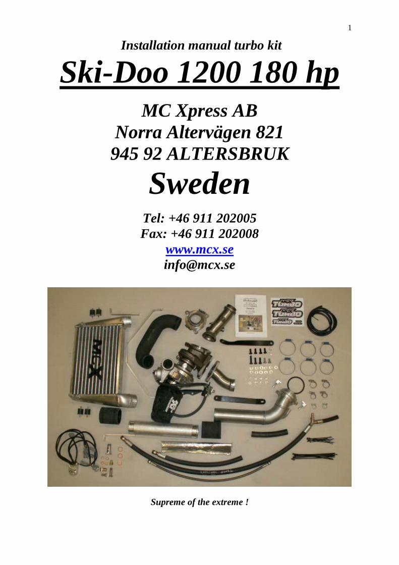
1. Cable ties 2. Oil outlet of the engine to the turbo. 3. Oil return of the turbo including three copper washers 4. Oil return nipple on the crankcase 5 O-ring inside the pressure tube going to the throttle body 6. Three M8 bolts +washers for the exhaust out of the turbo. (two are 20 mm and one 25 mm) 7. M8 Bolts, washers and nut to left stay for turbo. 8. Rubber mounts, nuts and washers to intercooler 9. Nipple with M5 thread to be installed on throttle body. 10. L-shaped clamps and bolts to fasten the pressure tube to the throttle body 11. M8 bolts, washers and one nut to secure turbo to exhaust manifold.
5
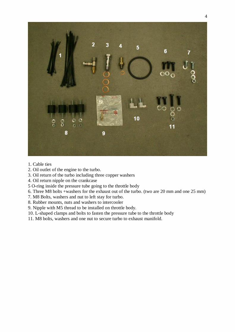
Before the installation
Take off the side plastic fairings the head lights etc. Take off the muffler, exhaust pipe and the exhaust manifold.
The exhaust pipe to the turbo shall be welded to the stock exhaust manifold. Use the jig supplied with the kit. Install the header and the exhaust pipe into the jig and weld around the joint.
Install the oil return nipple on the engine block. Use thread sealant on the threads of the nipple. Tighten not so hard. The nipple is rather weak.

6
Oil outlet to the turbo
The oil outlet from the engine to the turbo shall be installed where the oil pressure sensor is located. Remove the front/right engine mounting bracket from the engine and then remove the oil pressure sensor. Use the tool supplied with the kit when removing the oil pressure sensor. Install the nipple where the sensor has been located. Use thread sealant. Install the oil pressure sensor on top of the banjo bolt supplied with the kit. Install the T-fitting and the oil hose to the turbo and the banjobolt like the picture. Install the engine mounting bracket again.

7
Exhaust / Turbo installation Install the modified exhaust manifold to the cylinder head. Use the stock gasket between the cylinder head and the exhaust manifold. Install both oil return hoses under the turbo. (lose installation) The upper hose shall go to the valve cover/oil tank and the lower to the engine crankcase. (Picture of oil return hoses, see next chapter) Install the turbo to the exhaust manifold, loose installation. No gasket shall be used between the exhaust manifold and the turbo. Two steel stays shall be installed when installing the turbo to the exhaust manifold.
Lubricate the oil inlet of the turbo with motor oil. Install the oil hose to the turbo.

8
Left stay between the engine and the bracket on the turbo. Note that a steel bracket shall be installed at the turbo flange. (The longer bolts are supposed to be used on this side.)
Install the right stay like the picture. Final tighten everything after you have installed both stays to the turbo. Install the exhaust pipe out from the turbo and then the muffler. Use the stock exhaust gaskets and springs.

9
Oil return hose Two oil return hoses shall be installed. One hose shall go between the turbo and the nipple you have installed on the crankcase. The other hose shall be fitted to valve cover and hose to the oil tank behind the engine.
Note the hose routing of the hoses to and from the Turbo Control Valve (=TCV) Also note the vacuum hose to the blow off valve on the turbo.
Install a heat shield on the oil return hose and strap it against the chassis to avoid the hot exhaust pipe.
10
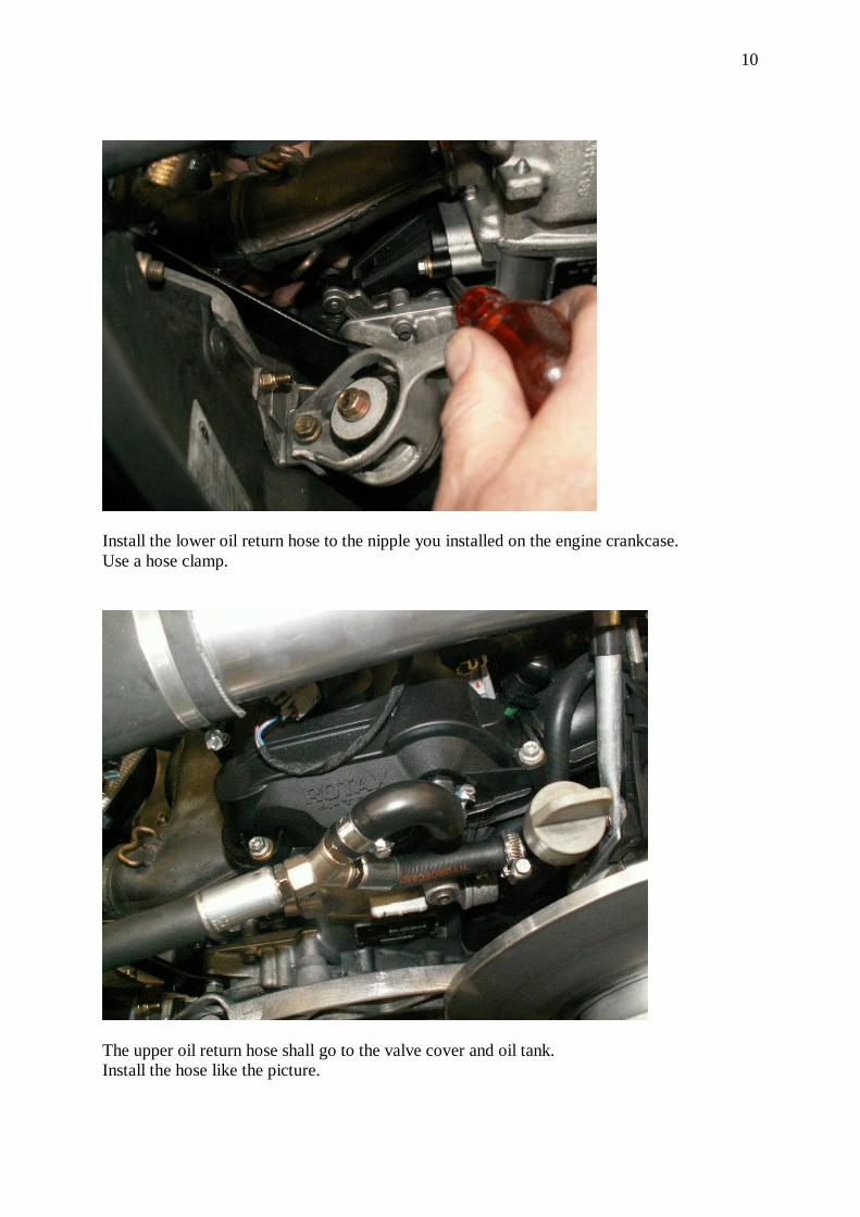
Install the lower oil return hose to the nipple you installed on the engine crankcase. Use a hose clamp.
The upper oil return hose shall go to the valve cover and oil tank. Install the hose like the picture.

11
Intercooler installation Install the intercooler in front of the turbo.
Install the intercooler like shown on the pictures.
The picture shows the left/upper intercooler stay. Install the aluminium stay for the stock air box when installing the upper stays for the intercooler.

12
Install the hose between the turbo and the intercooler.

13
Pressure tubes
Install a small nipple on the throttle body. Drill a 4 mm hole and use a M5 thread tap. An O-ring shall be placed inside the end of the pressure tube. Put some grease on the O-ring to make it slide in easier. Use the L-shaped holders to secure the pressure tube against the throttle body. To avoid the hose between the throttle body and the plastic plenum from blowing off in the future, we recommend to use “super glue” or similar between the rubber hose and the plastic. Install the vacuum hose against the nipple you just mounted. This hose shall be connected to the EFI-box and through a T fitting also to the blow off valve at the turbo.

14
EFI-box installation The stock fuel injection is not designed for turbo. An external EFI-box shall be installed. This box will correct the signals to the injectors so the air/fuel ratio always will be right during all kind of loads of the engine.
The EFI-box will also control the turbo pressure and engine power thanks to the TC-valve located close to the turbo. A barometer pressure sensor is built in inside the EFI-box and will inform about the outside pressure (=altitude) The EFI-box will –thanks to the TCV- automatically adjust up the turbo pressure if you go up in altitude to remain the full power of the engine. A wire from the EFI-box shall be connected to the TC-valve on the turbo.
The red wire to the EFI-box (+wire) shall be connected to a 12 volt ignition switch wire. Connect it to the red wire with green tracer located behind the stock fuse box above the battery. Use solder and insulate carefully.

15
Disconnect the stock wires to the injectors and plug them into the wires to the new EFI-box. Connect the EFI-box connectors to the EFI-box. You can connect any wire group to any injector, it does not matter.
16
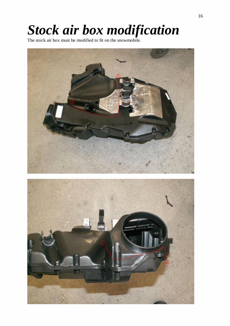
Stock air box modification The stock air box must be modified to fit on the snowmobile.

17
Try on the stock air box. Modify it until it fits fine.

18
Start the engine Check engine coolant and the oil level. Make sure everything is tightened properly. Start up the engine and search for leaks before you install the rest of the fairings.
Test-driving CAUTION: Always use high octane pump gas or race gas. Low octane may cause engine damages. Test-drive the snowmobile. CAUTION: Be very careful when you drive in the beginning. Check water level and oil level several times. Check for leaks and control so everything seems normal. It is very important that it is no air left in the cooling water system. The recommended turbo pressure is 35 kPa at sea level. (5Psi) The maximum power will then be 180 hp. At 2000 meters altitude, the pressure shall be 55 kPa (8Psi) Using higher turbo pressure may cause engine damages. If higher performance is requested, we recommend low compression pistons or that you use race gas. The air/fuel ratio shall also be recorded to avoid the engine from running lean. The maximum turbo pressure shall be tested! When testing turbo pressure, we recommend connecting a gauge via a T-connector on the same hose as the blow off valve is located. The test shall be made at full throttle for at least 4 seconds. If the pressure is too high, the test shall be stopped immediately, and the pressure shall be adjusted down. We recommend being careful when doing this test.
The turbo pressure can be adjusted by changing the spring pressure of the waste gate actuator. This is done by adjusting the length of the rod on top of the turbo. Shorter rod=higher turbo pressure.
19
When the turbo pressure is tested and everything seems to work fine, install the rest of the fairings. Good to know: Drive gently before the engine has reached proper temperature. When you shall turn off the engine, just let it idle for about 10 seconds. But drive very gently the last minute before you stop. Don’t use full power if the fuel level in the fuel tank is low, especially in steep hills. This can cause fuel starvation and engine damages.
Stickers
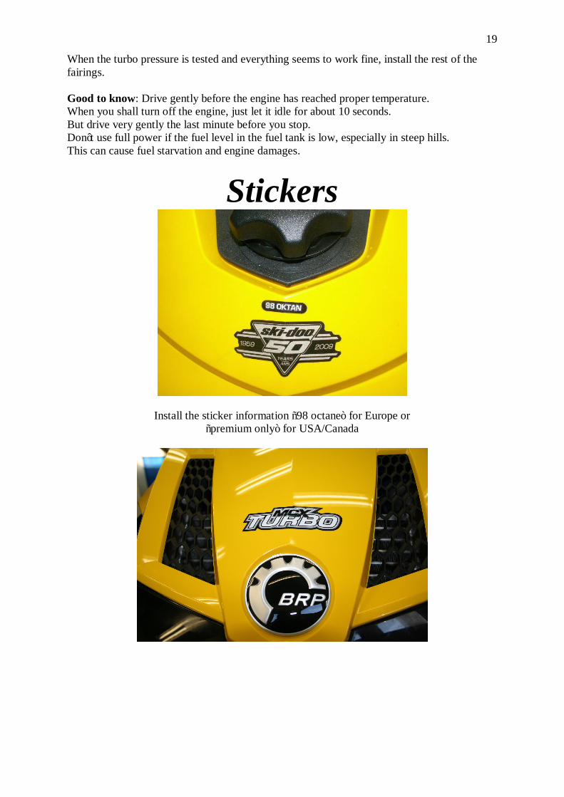
Install the sticker information “98 octane” for Europe or “premium only” for USA/Canada

20
Clutch modification (option)
The clutch needs to be adjusted to be able to handle the extra power. We recommend replacing the pins inside the primary clutch to heavier ones. New pins can be bought from us as an option. Take off the clutch from the crank shaft, take it apart when replacing the pins. The clutch must be pressed together with a pressure of 5000 kg (=11000 pound) before you install the clutch on the motor again.