MBRG-300 Modbus Router/Gateway - User manual Modbus Router/Gateway: User manual ... proconX Pty Ltd...
40
MBRG-300 Modbus Router/ Gateway User manual UMMBRG300-1101
Transcript of MBRG-300 Modbus Router/Gateway - User manual Modbus Router/Gateway: User manual ... proconX Pty Ltd...
MBRG-300Modbus Router/GatewayUser manual
UMMBRG300-1101

MBRG-300Modbus Router/Gateway: User manualCopyright © 2011 proconX Pty Ltd. All rights reserved.
Document revision history
2011-03-28 Initial Release
No part of this material may be reproduced or transmitted in any form or by any means or used to make any derivative work withoutexpress written consent from the copyright holders.
Modbus is a registered trademark of Schneider Automation Inc. proconX and FieldTalk are trademarks of proconX Pty Ltd. All otherproduct and brand names mentioned in this document may be trademarks or registered trademarks of their respective owners.
Disclaimer
proconX Pty Ltd makes no warranty for the use of its products, other than those expressly contained in the Company’s standard warrantywhich is detailed in the Terms and Conditions located on the Company’s Website. The Company assumes no responsibility for any errorswhich may appear in this document, reserves the right to change devices or specifications detailed herein at any time without notice,and does not make any commitment to update the information contained herein. No licenses to patents or other intellectual propertyof proconX are granted by the Company in connection with the sale of proconX products, expressly or by implication. proconX productsare not authorized for use as critical components in life support devices or systems.
Support & product feedback
We provide an electronic support and feedback system for our proconX products. It can be accessed through the following web link:
http://www.proconx.com/support
Your feedback and comments are always welcome. It helps improving this product.
Contact
For further information about the MBRG-300 product or this document please contact us at:
proconX Pty LtdPO Box 791Sumner QLD 4074AustraliaWebsite: http://www.proconx.com/mbrg300

UMMBRG300-1101 iii
Contents
Important user information ........................................................................................ vSafety Precautions ............................................................................................... vDocument conventions ....................................................................................... vi
1 Introduction ............................................................................................................. 1Features ............................................................................................................... 2Quick start checklist ............................................................................................ 2
2 Description .............................................................................................................. 3LED indicators ..................................................................................................... 3
3 Installation ............................................................................................................... 5Regulatory notes ................................................................................................. 5Unpacking, handling and storage ....................................................................... 5Before connecting anything ................................................................................ 5DIN rail mounting and removal .......................................................................... 6Mounting rules .................................................................................................... 6Powering the MBRG-300 ..................................................................................... 7Wiring the RS-485/422 interface ......................................................................... 7Wiring the RS-232 interface ................................................................................ 7Connecting Ethernet ........................................................................................... 8
4 Ethernet & IP configuration ................................................................................... 11IP setup using a web browser and a cross-over network cable .......................... 11IP setup using a terminal program like HyperTerminal ....................................... 12Temporarily changing the IP settings on your PC .............................................. 13
5 Web browser based management ......................................................................... 15Connecting to the MBRG-300 ........................................................................... 15Monitoring and diagnostic ................................................................................ 16
Device status .............................................................................................. 16Modbus connection status ........................................................................ 16Finding the firmware version and serial number ........................................ 18
Configuring and commissioning ........................................................................ 18Configuring Ethernet and IP ...................................................................... 18Configuring serial line Modbus .................................................................. 19Remote restarting the device ..................................................................... 20
6 Decommissioning ................................................................................................... 23Disconnecting .................................................................................................... 23Disposal ............................................................................................................. 23
A Specifications ........................................................................................................ 25Dimensions ........................................................................................................ 27
Glossary .................................................................................................................... 29Index ......................................................................................................................... 31
Figures2.1 Location of connectors ......................................................................................... 35.1 Device management and configuration via the web browser ............................. 155.2 Overview page .................................................................................................... 165.3 Modbus status page ........................................................................................... 175.4 About page ........................................................................................................ 18

iv UMMBRG300-1101
5.5 Ethernet and IP settings page ............................................................................ 185.6 IP settings changed confirmation ....................................................................... 195.7 Modbus settings page ........................................................................................ 195.8 Restart device page ............................................................................................ 205.9 Restart confirmation page .................................................................................. 20A.1 Enclosure dimensions ......................................................................................... 27
Tables2.1 LED diagnostic codes ............................................................................................ 43.1 Power supply connector pinout ............................................................................ 73.2 Modbus RS-232 connector pinout ........................................................................ 83.3 Ethernet connector pinout ................................................................................... 8

Important user information
UMMBRG300-1101 v
Important user informationThis manual explains how to install, operate and configure a MBRG-300. This device mayonly be used for the applications described in this document.
This manual is to be used with a MBRG-300 with firmware version 1.6.
These instructions are intended for use by trained specialists in electrical installationand control and automation engineering, who are familiar with the applicable nationalstandards and safety procedures.
Safety Precautions
ELECTRICAL HAZARD
• This equipment must be installed and serviced only by qualified personnel. Suchwork should be performed only after reading this entire set of instructions.
• Before performing visual inspections, tests, or maintenance on this equipment,disconnect all sources of electric power. Assume that all circuits are live until theyhave been completely de-energized, tested, and tagged. Pay particular attentionto the design of the power system. Consider all sources of power, including thepossibility of backfeeding.
• Apply appropriate personal protective equipment and follow safe electricalpractices.
• Turn off all power supplying the equipment in which the MBRG-300 is to beinstalled before installing, wiring or removing the MBRG-300.
• Always use a properly rated voltage sensing device to confirm that power is off.• The successful operation of this equipment depends upon proper handling,
installation, and operation. Neglecting fundamental installation requirementsmay lead to personal injury as well as damage to electrical equipment or otherproperty.
Failure to follow these instructions could result in death or serious injury!

vi UMMBRG300-1101
Document conventionsThroughout this manual we use the following symbols and typefaces to make you awareof safety or other important considerations:
Indicates a potentially hazardous situation that, if not avoid-ed, could result in death or serious injury.
Indicates a potentially hazardous situation that, if not avoid-ed, could result in damage to equipment.
Indicates information that is critical for successful applicationand understanding of the product.
Provides other helpful user information that does not fall inabove categories.
Provides supplemental user information.
Acronym This typeface is used to introduce acronyms or productnames.
Command This typeface is used to represent commands, prompts, inputfields and filenames. In the context of programming it is usedfor functions, variable names, constants or class names.
Placeholder This typeface is used to represent replacable text. Replaceabletext is a placeholder for data you have to provide, like file-names or command line arguments.
User input This typeface is used to represent data entered by the useror buttons.
Screen output Screen output or program listing

Introduction
UMMBRG300-1101 1
Chapter 1. IntroductionThe MBRG-300 is a Modbus/TCP to Modbus RTU gateway.
The gateway features one serial port which can be configured as either RS-232, RS-485or RS-422 and an Ethernet port. It can be mounted on a DIN rail.
Usage and configuration of the gateway is simple and conveniently performed using aweb browser which connects to the embedded web server.
Possible areas of application are:
• PLC connection
• Operator panel interfacing
• HMIs
• SCADA integration
• Remote control & monitoring
• Data logging

2 UMMBRG300-1101
Features
The MBRG-300 gateway provides the following key features:
• Modbus/TCP protocol (Ethernet)
• Modbus RTU protocol (either RS-232, RS-485 or RS-422, software configurable)
• Embedded web server for easy configuration and commissioning using a web browser
• Firmware upgradeable via Ethernet
• DIN rail mountable
• 24 V DC (10-30 V) power supply
• Status LEDs for power, Ethernet link, device status and communication status
Quick start checklist• Read this set of instructions properly and in its entirety.
• Mount the unit.
• Connect the power. Do not connect yet serial ports.
• Configure the Ethernet communications settings with a web browser (using anEthernet crossover cable) or with a terminal program like HyperTerminal (using a nullmodem cable)
• Configure the serial line communication settings.
• Configure the operational aspects of the device.
• Wire serial line interfaces.

Description
UMMBRG300-1101 3
Chapter 2. DescriptionThe power and RS-485/RS-422 terminals are placed on the top side of the unit. TheRS-232 and Ethernet connectors are placed on the bottom side of the unit as shown inthe following illustration:
TOP VIEW
BOTTOM VIEW
FRONT VIEW
Figure 2.1: Location of connectors
Clear front cover Serial port 1 RS-232 connector Serial port 2 RS-232 connector Ethernet connector DIN rail clip Power LED Ethernet link LED Device status LED Communication status LED Power terminals Serial port 1 and 2 RS-485 or serial port 1 RS-422 terminals
LED indicatorsFour LEDs located at the front panel indicate the status of the device. The LEDs assistmaintenance personnel in quickly identifying wiring or communication errors.
A LED test is exercised at power-up, cycling each LED off, green and then red forapproximately 0.25 seconds. At the same time the power-on self test of the device isperformed.

4 UMMBRG300-1101
The following table outlines the indicator condition and the corresponding status afterthe power-on self test has been completed:
LED Function Condition Indication
Off No power applied to the device.Power Power
Green Power supply OK
Off No Ethernet linkLink Ethernet link
Green Ethernet link OK
Off The device has an unrecoverable fault; may need replacing.
Flashing green1 s rate
Device operational but needs commissioning due to configurationmissing, incomplete or incorrect.
Green The device is operating in normal condition.
Flashing red1 s rate
Device operational but has a fault listed which requires acknowledg-ment.
Status1 Device status
Red The device has an unrecoverable fault; may need replacing. Flashingsequence and rate of Status2 LED indicates fault class.
Off No Modbus/TCP connection.Status2 Communica-
tion status Green Modbus/TCP connection established.
Table 2.1: LED diagnostic codes

Installation
UMMBRG300-1101 5
Chapter 3. Installation
Regulatory notes1. The MBRG-300 is suitable for use in non-hazardous locations only.
2. The MBRG-300 is not authorized for use in life support devices or systems.
3. Wiring and installation must be in accordance with applicable electrical codes inaccordance with the authority having jurisdiction.
4. This is a Class A device and intended for commercial or industrial use. This equipmentmay cause radio interference if used in a residential area; in this case it is theoperator’s responsibility to take appropriate measures.
5. The precondition for compliance with EMC limit values is strict adherence to theguidelines specified in this set of instructions. This applies in particular to the areaof grounding and shielding of cables.
FCC Notice (USA only)
This equipment has been tested and found to comply with the limits for a Class Adigital device, pursuant to Part 15 of the FCC Rules. These limits are designed to providereasonable protection against harmful interference when the equipment is operatedin a commercial environment. This equipment generates, uses, and can radiate radiofrequency energy and, if not installed and used in accordance with the instructionmanual, may cause harmful interference to radio communications. Operation of thisequipment in a residential area is likely to cause harmful interference in which case theuser will be required to correct the interference at his own expense.
Industry Canada Notice (Canada only)
This Class A digital apparatus complies with Canadian ICES-003.
Unpacking, handling and storage1. Please read this set of instructions. carefully before fitting it into your system.
2. Keep all original packaging material for future storage or warranty shipments of theunit.
3. Do not exceed the specified temperatures.
Before connecting anything1. Before installing or removing the unit or any connector, ensure that the system power
and external supplies have been turned off.

6 UMMBRG300-1101
2. Check the system supply voltage with a multimeter for correct voltage range andpolarity.
3. Connect the power supply cable and switch on the system power. Check if the PowerLED is lit.
4. Turn off system power.
5. Connect all I/O cables.
6. Once you are certain that all connections have been made properly, restore thepower.
DIN rail mounting and removalThe MBRG-300 gateway is designed to be mounted on a 35 mm DIN rail according toDIN/EN 50022. The enclosure features a 35 mm profile at the back which snaps into theDIN rail. No tools are required for mounting. Please observe the rules outlined in thesection called “Mounting rules”.
2
1
Click
DIN rail
To mount the unit on a DIN rail, slot the top part of theMBRG-300 into the upper guide of the rail and lower theenclosure until the bottom of the red hook clicks intoplace.
Slide down 21
To remove the MBRG-300 from the DIN rail, use a screwdriver as a lever by inserting it in the small slot of the redhook and push the red hook downwards. Then remove theunit from the rail by raising the bottom front edge of theenclosure.
Mounting rulesThe enclosure provides protection against solid objects according to IP 20 / NEMA Type 1protection rating. When mounting the unit observe the following rules:
• No water splash and water drops
• No aggressive gas, steam or liquids

Installation
UMMBRG300-1101 7
• Avoid dusty environments.
• Avoid shock or vibration
• Do not exceed the specified operational temperatures and humidity range.
• Mount inside an electrical switchboard or control cabinet.
• Make sure there is sufficient air ventilation and clearance to other devices mountednext to the unit.
• Observe applicable local regulations like EN60204 / VDE0113.
Powering the MBRG-300
Before connecting power please follow the rules in the section called “Safety Precau-tions” and the section called “Before connecting anything”.
Power is supplied via a 3.81 mm 2-pin pluggable terminal block located at the top sideof the mounted unit (refer to Figure 2.1, “Location of connectors”). The following tableand picture shows the power terminal socket pinout:
V+
V-
1Pin Signal Function
1 V+ Positive voltage supply (10 - 30 V DC)
2 V- Negative voltage supply, DC power return
Table 3.1: Power supply connector pinout
Make sure that the polarity of the supply voltage is correct before connecting anydevice to the serial ports! A wrong polarity can cause high currents on the groundplane between the V- power supply pin and the serial port ground pins, which cancause damage to the device.
Wiring the RS-485/422 interfaceThe RS-485/422 port is used for integrating the MBRG-300 into a two-wire or four-wireModbus over Serial Line network. The use of either the RS-485 or RS-422 interface mustbe configured using the web interface (See the section called “Configuring serial lineModbus”). The MBRG-300 is a Modbus Master device on this interface.
Wiring the RS-232 interfaceThe RS-232 port can alternativly be used for serial communication to a Modbus Slavedevice instead of RS-485. The use of the RS-232 interface must be configured using theweb interface (See the section called “Configuring serial line Modbus”). The MBRG-300is a Modbus Master device on this interface.
8 UMMBRG300-1101
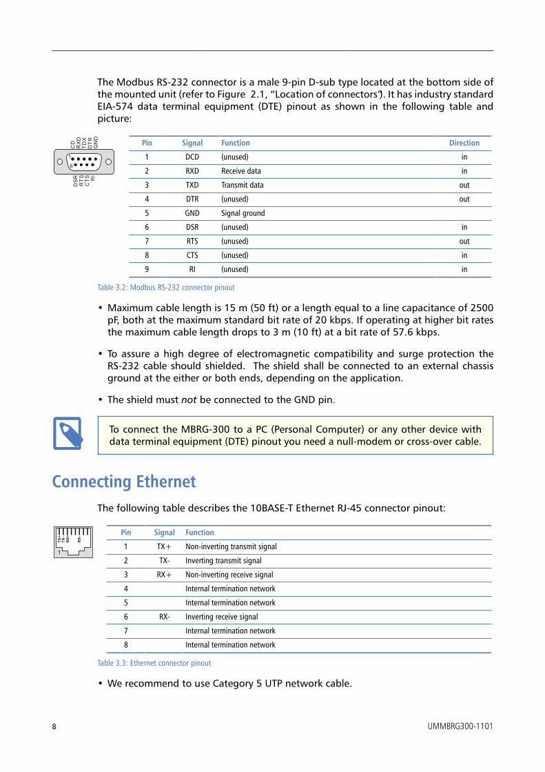
The Modbus RS-232 connector is a male 9-pin D-sub type located at the bottom side ofthe mounted unit (refer to Figure 2.1, “Location of connectors”). It has industry standardEIA-574 data terminal equipment (DTE) pinout as shown in the following table andpicture:
GN
D
TDX
CTS
DTR
RI
RX
DR
TS
1
6
CD
DS
R
Pin Signal Function Direction
1 DCD (unused) in
2 RXD Receive data in
3 TXD Transmit data out
4 DTR (unused) out
5 GND Signal ground
6 DSR (unused) in
7 RTS (unused) out
8 CTS (unused) in
9 RI (unused) in
Table 3.2: Modbus RS-232 connector pinout
• Maximum cable length is 15 m (50 ft) or a length equal to a line capacitance of 2500pF, both at the maximum standard bit rate of 20 kbps. If operating at higher bit ratesthe maximum cable length drops to 3 m (10 ft) at a bit rate of 57.6 kbps.
• To assure a high degree of electromagnetic compatibility and surge protection theRS-232 cable should shielded. The shield shall be connected to an external chassisground at the either or both ends, depending on the application.
• The shield must not be connected to the GND pin.
To connect the MBRG-300 to a PC (Personal Computer) or any other device withdata terminal equipment (DTE) pinout you need a null-modem or cross-over cable.
Connecting EthernetThe following table describes the 10BASE-T Ethernet RJ-45 connector pinout:
TX+
TX-
RX-
RX+
1
Pin Signal Function
1 TX+ Non-inverting transmit signal
2 TX- Inverting transmit signal
3 RX+ Non-inverting receive signal
4 Internal termination network
5 Internal termination network
6 RX- Inverting receive signal
7 Internal termination network
8 Internal termination network
Table 3.3: Ethernet connector pinout
• We recommend to use Category 5 UTP network cable.

Installation
UMMBRG300-1101 9
• Maximum cable length is 100 m (3000 ft).

This page intentionally left blank
10 UMMBRG300-1101

Ethernet & IP configuration
UMMBRG300-1101 11
Chapter 4. Ethernet & IP configurationBefore configuring the MBRG-300, obtain a unique static IP address, subnet mask, anddefault gateway address from your network administrator.
The factory default IP address of the MBRG-300 is 169.254.0.10 which is in the AutomaticPrivate IP Addressing (APIPA) address range.
There are several methods of configuring the unit’s IP address:
1. Removing your PC from your corporate network and using a cross-over networkcable (see the section called “IP setup using a web browser and a cross-over networkcable”).
2. Via the Serial Port 1 and a terminal program like HyperTerminal (see the section called“IP setup using a terminal program like HyperTerminal”).
3. Leaving your PC connected to your corporate network and temporarily changing theIP settings on your PC to match the subnet of the MBRG-300 (see the section called“Temporarily changing the IP settings on your PC”).
In order to connect to the MBRG-300 via TCP/IP, your PC must be on same IP subnetas the gateway. In most situations this means that the first three numbers of theIP address have to be identical.
IP setup using a web browser and a cross-over network cableThis method applies only to operating systems like Windows, which support APIPA(Automatic Private IP Addressing). It also requires your PC to be configured for DHCP. Ifyour computer is configured with a static IP address, follow the procedure in the sectioncalled “Temporarily changing the IP settings on your PC”.
1. Disconnect your PC from your corporate network. If your computer is configured forDHCP it should now automatically fall back to use a default IP address from the APIPArange 169.254.x.x (Windows PCs only).
2. Connect an Ethernet crossover cable from the MBRG-300 to the computer.
3. Start Internet Explorer.
4. In the address box, type 169.254.0.10 and then press Enter.
5. Click Configuration… and then Ethernet & IP in the menu on the left side ofthe page.
6. Enter the IP address, subnet mask, and gateway address assigned to your MBRG-300,then click Save.
7. Reconnect your computer to your corporate network.
12 UMMBRG300-1101
IP setup using a terminal program like HyperTerminal
1. Connect a null modem RS-232 cable between your PC and the MBRG-300’s SerialPort 1.
2. In Windows XP, click Start, point to All Programs, point to Accessories, pointto Communications, and then click HyperTerminal.
3. When HyperTerminal starts, it opens a dialog box and asks for a name for the newconnection. Enter a name (for example, deviceconfig) then click OK.
4. The Connect to dialog opens. Select the COM port you will be using in the Connectusing drop-down list box, then click OK.
5. Select 9600, 8, None, 1, None in the COM Properties dialog, then click OK.
6. HyperTerminal is now connected to the serial line.
7. Keep the space bar pressed in HyperTerminal and power-cycle your device at thesame time.
8. A menu should appear after one or two seconds showing device information, thecurrent IP configuration and a > prompt.
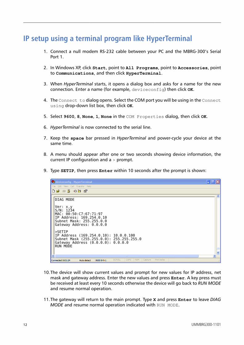
9. Type SETIP, then press Enter within 10 seconds after the prompt is shown:
DIAG MODE
Ver: x.yS/N: 1234MAC: 00:50:C7:67:71:97IP Address: 169.254.0.10Subnet Mask: 255.255.0.0Gateway Address: 0.0.0.0
>SETIPIP Address (169.254.0.10): 10.0.0.100Subnet Mask (255.255.0.0): 255.255.255.0Gateway Address (0.0.0.0): 0.0.0.0RUN MODE
10.The device will show current values and prompt for new values for IP address, netmask and gateway address. Enter the new values and press Enter. A key press mustbe received at least every 10 seconds otherwise the device will go back to RUN MODEand resume normal operation.
11.The gateway will return to the main prompt. Type X and press Enter to leave DIAGMODE and resume normal operation indicated with RUN MODE.

Ethernet & IP configuration
UMMBRG300-1101 13
Temporarily changing the IP settings on your PC
This method involves manually assigning an IP address to your PC in the same subnet asthe gateway. The default subnet of the gateway is 169.254.0.0/16.
1. Connect the MBRG-300 to your Ethernet network.
2. On a Windows PC, open the Control Panel and double-click on NetworkConnections. Right-click on the Network Connection associated with your networkadapter and select Properties:
This will show the Local Area Connection Properties Dialog:

14 UMMBRG300-1101
3. Select the Internet Protocol (TCP/IP) entry and click on Properties to openthe TCP/IP Properties dialog as shown below:
4. Write down your current settings so they can be restored later.
5. Select Use the following IP address and configure a static IP address inthe same subnet as the device, for example 169.254.0.1 and the subnet mask255.255.0.0. Click OK to save the changes.
6. Start Internet Explorer.
7. In the address box, type 169.254.0.10 and then press Enter.
8. Click Configuration… and then Ethernet & IP in the menu on the left side ofthe page.
9. Enter the IP address, subnet mask, and gateway address assigned to your MBRG-300,then click Save.
10.Restore your computer’s original settings.

Web browser based management
UMMBRG300-1101 15
Chapter 5. Web browser based managementThe MBRG-300 incorporates an embedded web server. This allows you to connect to thedevice and monitor and configure it using a web browser. Most browsers should work,provided they support JavaScript. We recommend Internet Explorer 6.0 or higher.
Connecting to the MBRG-300Once you made sure that your PC is configured to be on the same subnet as theMBRG-300, start your web browser. In the address box, type the IP address of yourdevice (169.254.0.10 is the default), and then press Enter. (See Chapter 4, Ethernet &IP configuration)
The web browser will establish communication with the embedded web server and anoverview page similar to the following picture will appear:
Figure 5.1: Device management and configuration via the web browser
Gateway IP address Main menu Configuration sub-menu Information area
Use the menu bar shown on the left side to navigate the different pages.

16 UMMBRG300-1101
In order to connect to the MBRG-300 via TCP/IP, your PC must be on same IP subnetas the gateway. In most situations this means that the first three numbers of theIP address have to be identical.
Monitoring and diagnosticThe MBRG-300 offers several web pages which allow monitoring of the status of thedifferent communication networks and the device performance.
Device status
The Overview page shows the principal device status as shown in the following picture:
Figure 5.2: Overview page
The value shown in the Device row represents the device status register which keepstrack of run-time faults. All run-time faults are latched and must be reset by the user.The following faults can be listed here:
OKThe device is fault free.
Watchdog resetThis warning indicates that the device was reset by it’s internal watchdog supervisioncircuit.
Brown out resetThis warning indicates that the device was reset by it’s internal supply voltagemonitoring circuit. This fault occurs when the supply voltage drops below the lowerlimit.
Device out of memoryThis warning indicates that the internal dynamic memory has been exhausted anddue to this a certain function could not be completed.
Device configuration data write failureThis alarm indicates that the configuration data could not be written to the non-volatile memory. Configuration data changes will be lost once the device is power-cycled or reset.
Reset to factory defaultsThis alarm indicates that the device' configuration data was reset to factory defaults.The device requires re-commissioning.
Modbus connection status
The Modbus Status page shows status and statistics about the Modbus traffic. Thesevalues provide valuable information used to troubleshoot Modbus network problems.This page is automatically updated every 5 seconds.

Web browser based management
UMMBRG300-1101 17
Figure 5.3: Modbus status page
This page shows accumulated readings since the MBRG-300 was last activated orreset. If power to the MBRG-300 is lost, all cumulative values are reset to zero.
The following statistics are maintained:
TCP statusStatus of the TCP/IP connection as per TCP finite state machine (refer to RFC 793).If no client is connected the status indicates LISTEN. If a client is connected, it’s IPaddress is shown.
Accumulative connectionsA counter that increments each time a client opens a Modbus/TCP connection.
RequestsA counter that increments each time an inbound request message is successfullyreceived.
RepliesA counter that is incremented each time a reply message is sent back to the master.This includes exception replies.
CRC errorsA counter that increments each time a message is received that has a CRC that doesnot match what is calculated. Typically the result of wiring issues. Messages with CRCerrors are discarded and not replied to.
Invalid framesA counter that increments each time a malformed Modbus frame is detected.Malformed frames are for example messages larger than the allowed maximum PDUsize defined in the Modbus standards. This can be caused by non-Modbus traffic onthe network.
Rx time-outs (Modbus serial line)A counter that increments each time an inter-character time-out occurred during thereception of an inbound message.
Rx time-outs (Modbus/TCP)A counter that increments if the master connection has timed out. Subsequently theconnection is terminated by the MBRG-300. A time-out occurs if no Modbus requestis received from a connected client within a 10 second period.
Tx time-outsNumber time-outs occurred when attempting to send a reply message.
The cumulative diagnostic data is reset when the device is power cycled or reset. Thedata is also reset by pressing the Clear Counter button.
18 UMMBRG300-1101
Finding the firmware version and serial number
Click on the About menu entry on the menu bar to show the product information asshown below:
Figure 5.4: About page
This product information is important for service and support inquiries. The followingproduct information is provided:
Product nameThe name of the product.
Hardware versionMBRG-300 hardware version.
Firmware versionThe firmware version that is installed on the MBRG-300.
Serial numberThe serial number of the MBRG-300. The serial number is specific to your device.
Configuring and commissioningThe configuration pages are accessed by clicking on the Configuration… menu entryon the menu bar which then expands a configuration sub-menu. All configurationsettings are kept in the device' non-volatile memory.
If you make changes to any settings, remember to save each page before changingto a different page!
Configuring Ethernet and IP
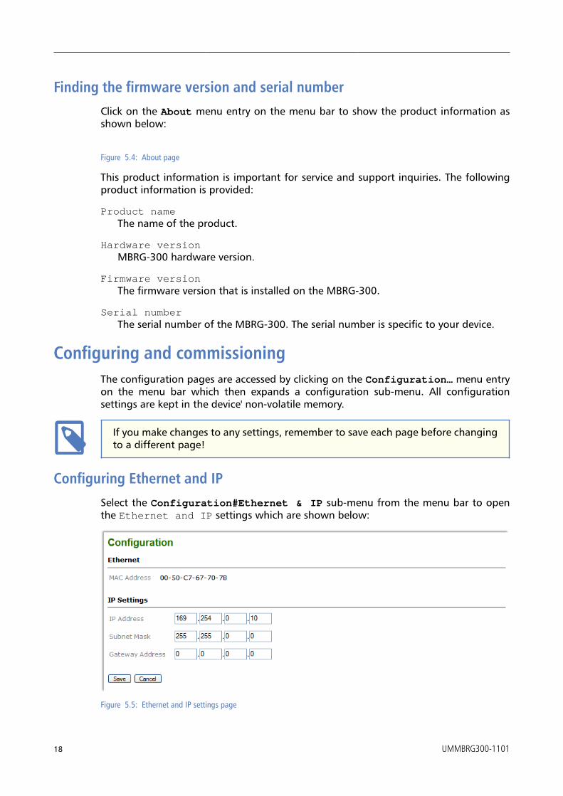
Select the Configuration#Ethernet & IP sub-menu from the menu bar to openthe Ethernet and IP settings which are shown below:
Figure 5.5: Ethernet and IP settings page

Web browser based management
UMMBRG300-1101 19
The following Ethernet parameters are shown:
MAC addressThe device' unique MAC address. This number is hard coded and cannot be changed.
The following Internet protocol (IP) settings can be entered:
IP addressThe IP address assigned to this device.
Subnet mask (also known as indexterm2:[network mask])If you have a router, enter the subnet mask for the segment to which this device isattached.
Gateway addressIf your network segment has a router, enter its IP address here. Otherwise leave theaddress as 0.0.0.0.
Once you click Save the new settings are stored and applied instantly. The new settingsare confirmed with the following page:
Figure 5.6: IP settings changed confirmation
Please write down the new IP address so you are able to communicate with thedevice in the future!
Configuring serial line Modbus
The Modbus settings for serial line can be configured to match the network configurationof your Modbus master device. Select the Configuration#Modbus sub-menu from themenu bar to open the Modbus settings which are shown below:
Figure 5.7: Modbus settings page
The following Modbus settings can be entered:
Physical layerCan be set to two-wire RS-485, RS-422 or RS-232 mode. RS-485 is the default.Depending on this setting either the D-sub (RS-232) connector or the terminal blockconnector (RS-485/422) of the MBRG-300 is utilized. The (RS-485 + RS-422) modeis a special mode which allows operating one RS-422 device and a RS-485 bus onethe same serial interface.
Transmission modeOnly RTU mode can be selected here.

20 UMMBRG300-1101
Baud rate9600 and 19200 are the most common baud rates for Modbus. 19200 is the defaultsetting.
Data bitsOnly 8 data bits can be selected here which is a requirement for RTU.
Stop bitsCan be configured to be 1 or 2. The Modbus standard mandates that 2 stop bits areconfigured when using no parity.
ParityChanges parity mode to either none, even or odd. The default parity mode forModbus is even parity.
Slave ID for RS-422 nodeThis setting is only valid for the combined RS-485 + RS-422 mode which allowsoperating one RS-422 device and a RS-485 bus one the same serial interface. Thissetting determines based on the slave ID whether a Modbus message is transmittedonto the RS-485 bus or the RS-422 interface. Configure here the slave ID of the RS-422device.
Once you click Save the new settings are stored and applied instantly. A confirmationmessage is shown.
Remote restarting the device
You can perform a remote restart of the device from the web interface. A remote restartis similar to power cycling the device. Possibly connected clients are disconnected andcommunication is interrupted until the device has rebooted.
To perform a remote restart, click on the Configuration sub-menu and then click onthe Restart menu entry. This will open the device restart page as shown below:
Figure 5.8: Restart device page
Click on the Restart button to perform a restart of the device. The restart is confirmedwith the following notification:
Figure 5.9: Restart confirmation page
Web browser based management
UMMBRG300-1101 21
Please allow a few seconds before continuing working with the device as it has to fullystart-up first, before being able to respond to further web browser requests.
After a remote restart a Watchdog reset alarm is shown on the device' home page.This is a side-effect of the remote restart procedure and the alarm shall be ignoredand cleared.

This page intentionally left blank
22 UMMBRG300-1101

Decommissioning
UMMBRG300-1101 23
Chapter 6. DecommissioningBefore disconnecting the MBRG-300 unit please follow the rules in the section called“Safety Precautions”.
Disconnecting
1. Ensure that the system power and external supplies have been turned off.
2. Disconnect power supply plug.
3. Disconnect all I/O cables.
4. Remove the MBRG-300 from the DIN rail following the procedure described in thesection called “DIN rail mounting and removal”.
Disposal
This product must be disposed of at a specialized electronic waste recycling facility.Do not dispose of in domestic waste.

This page intentionally left blank
24 UMMBRG300-1101

Specifications
UMMBRG300-1101 25
Appendix A. SpecificationsProduct name MBRG-300
Interfaces
Ethernet 1
Serial ports 2, software configurable as either 2 x RS-232 or 2 x RS-485 or 1 x RS-232 + 1 xRS-485 or 1 x RS-422
User interface
LED indicators Power (green), Ethernet link (green), 2 status (bi-color red/green)
Monitoring & configuration Web browser based
Diagnostic
High availability features Watchdog supervision, brown-out detection
Serial Port 1 RS-232 interface
Connector male 9-pin D-sub, DTE, EIA-574 pin-out
Physical layer EIA-232-F
Isolation non-isolated
Signals RXD, TXD, RTS, CTS, DTR, DSR, DCD, RI
Speed 300, 600, 1200, 2400, 4800, 9600, 19200, 57600, 115200 bps
Protocols Modbus RTU master
Serial Port 1 RS-485/RS-422 interface
Connector 3.81 mm 6-pin pluggable terminal block header
Physical layer EIA-485-A, 2-wire or 4-wire
Isolation non-isolated
Speed 300, 600, 1200, 2400, 4800, 9600, 19200, 57600, 115200 bps
Max. number of nodes 32
Protocols Modbus RTU master
Serial Port 2 RS-232 interface
Connector male 9-pin D-sub, DTE, EIA-574 pin-out
Physical layer EIA-232-F
Isolation non-isolated
Signals RXD, TXD
Speed 9600 bps
Protocols Modbus RTU master
Serial Port 2 RS-485 interface
Connector 3.81 mm 6-pin pluggable terminal block header
Physical layer EIA-485-A, 2-wire
Isolation non-isolated
Speed 300, 600, 1200, 2400, 4800, 9600, 19200, 57600, 115200 bps
Max. number of nodes 32
Protocols Modbus RTU master
Ethernet port
Connector 8-pin RJ-45 socket for Cat 5 UTP
Physical & Data Link Layer Layer IEEE 802.3i 10BASE-T
Isolation 1.5 kV galvanic

26 UMMBRG300-1101
Speed 10 Mbit/s
Max. cable length 100 m (328 ft)
Ethernet frame types 802.3
Protocols Modbus/TCP slave, HTTP, IP, TCP, ARP
Concurrent connections 4 Modbus/TCP slave, 2 HTTP
Power supply
Connector 3.81 mm 2-pin pluggable terminal block header
Voltage 10-30 V DC
Current 30 mA typical @ 24 V DC
Intrinsic consumption 750 mW
Electromagnetic compatibility
Emissions (radiated and conducted) AS/NZS CISPR 22 / EN 55022 (Class A)
Immunity EN 55024
Electrostatic discharge EN 61000-4-2
Radiated RF EN 61000-4-3
Fast transients EN 61000-4-4
Conducted RF EN 61000-4-6
Enclosure
Material Self-extinguishing PC/ABS blend (UL 94-V0)
Mounting 35 mm DIN rail (EN 60715)
Classification / Type rating IP 20 / NEMA Type 1
Cooling Convection
Environmental
Operating temperature 0 to 60 °C / 32 to 140 °F
Storage temperature -25 to 85 °C / -13 to 185 °F
Humidity rating 10 to 95% relative humidity, non condensing
Operating ambience Free from corrosive gas, minimal dust
Physical
Dimensions 101 x 22.5 x 120 mm / 3.98 x 0.886 x 4.72 in
Weight 0.12 kg / 0.265 lb
Compliance
Australia C-Tick
Europe CE, RoHS
USA FCC Part 15 (Class A)
Canada ICES-003 (Class A)
Specifications
UMMBRG300-1101 27
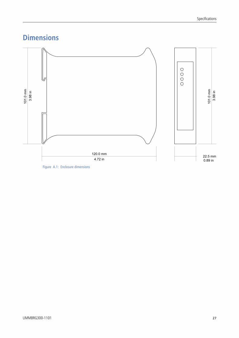
Dimensions
101.
0 m
m
120.0 mm
3.98
in
4.72 in 0.89 in22.5 mm
101.
0 m
m3.
98 in
Figure A.1: Enclosure dimensions

This page intentionally left blank
28 UMMBRG300-1101

Glossary
UMMBRG300-1101 29
Glossary
10BASE-T10 Mbit/s twisted pair Ethernet standard.Standardized in IEEE 802.3i
APIPAAutomatic Private IP Addressing
Class AClass A equipment is that used incommercial or light industrial environments.
DCEData communications equipment. DTE andDCE devices have different pinouts forRS-232 connectors. A Modem for example isa DCE.
DIN rail35 mm wide mounting bracket standardizedin DIN/EN 50022.
DTEData terminal equipment. DTE and DCEdevices have different pinouts for RS-232connectors. A PC for example is a DTE.
EIA-232Standard for serial transmission of databetween two devices, also known as RS-232and V.24.
EIA-422ANSI/TIA/EIA-422 standard for serialtransmission of data between two devices,also known as RS-422 and V.11.
EIA-485ANSI/TIA/EIA-485 standard for serialtransmission of data between multipledevices, also known as RS-485.
EIA-574Standard for the pinout of serial D-subconnectors.
EMCElectromagnetic compatibility
EMIElectromagnetic interference
ESDElectrostatic discharge. ESD can damageelectronic equipment.
EthernetThe standard for local area networksdeveloped jointly by Digital EquipmentCorp., Xerox, and Intel. Ethernet is used asthe underlying transport vehicle by severalupper-level protocols, including TCP/IP.
GatewayA network device that passes data betweendifferent networks or fieldbusses.
Gateway addressThe IP address of the gateway or router usedto access the Internet from the local arenetwork.
IEEEInstitute of Electrical and ElectronicsEngineers
IPIngress Protection Rating standardized inIEC 60529. Standard for various grades ofelectrical enclosures.
IP addressA numeric address used by computer hoststo transmit and receive information over theInternet.
ISOInternational Standards Organisation
MAC addressEvery piece of Ethernet hardware has aunique number assigned to it called it’s MACaddress. MAC addresses are administeredand assigned by the IEEE organization.
ModbusFieldbus protocol used in the processautomation industry. It uses a masterand slave structure. Originally developedby Modicon, now part of SchneiderAutomation.

30 UMMBRG300-1101
NEMANational Electrical ManufacturersAssociation. NEMA defines standards forvarious grades of electrical enclosures.
NodeA communications device on the network.
PC/ABSPolycarbonate-ABS. Widely usedthermoplastic material.
PLCProgrammable Logic Controller
RS-232See EIA-232.
RS-422See EIA-422.
RS-485See EIA-485.
Subnet maskA numeric address used in conjunction withan IP address to segment network traffic;used to restrict transmissions to certainsubnets.
SwitchA device that facilitates transmissionsbetween nodes in a star-formed network.
TCP/IPTransport Control Protocol/InternetProtocol. Connection-orientated transferprotocol.
TelnetA network protocol (RFC 854) for characterbased terminal access to remote machines.
UL 94Plastics flammability standard released byUnderwriters Laboratories of the USA.

Index
UMMBRG300-1101 31
IndexAAbout, 18Accumulative connections, 17APIPA, 11
BBaud rate, 20Brown out reset, 16
Ccable
RS-232, 8cable length
Ethernet length, 9RS-232, 8
Class A, 5connector
Ethernet, 8location, 3power, 7RS-232, 8
CRC errors, 17cross-over network cable, 11
DData bits, 20default IP address, 11Device configuration data write failure, 16Device out of memory, 16device status register, 16DIN rail
mounting, 6removal, 6
Disconnecting, 23Disposal, 23
Eelectronic waste, 23embedded web server, 15EMC, 5enclosure
DIN rail clip, 3front cover, 3mounting, 6red hook, 6removal, 6
Ethernet, 8, 19
settings, 19
Ffaults, 16features, 2Firmware version, 18
GGateway address, 19grounding, 5
HHardware version, 18HyperTerminal, 12
IInvalid frames, 17IP
settings, 11, 19IP address, 19
JJavaScript, 15
LLED, 3, 3
MMAC address, 19Modbus
settings, 19status, 17
mounting, 6rules, 6
PParity, 20Physical layer, 19pinout
Ethernet, 8power, 7RS-232, 8
power, 7Product name, 18
Rrecycling, 23remote restart, 20removal, 6Replies, 17

32 UMMBRG300-1101
Requests, 17Reset to factory defaults, 16restart, 20RJ-45, 8RS-232, 8run-time faults, 16Rx time-outs, 17
SSerial number, 18settings
Ethernet, 19IP, 11, 19Modbus, 19
shield, 8shielding, 5shock, 7Slave ID for RS-422 node, 20Specifications, 25Stop bits, 20storage, 5Subnet mask, 19supply voltage, 7
TTCP status, 17temperature
operating, 7terminal program, 12Transmission mode, 19Tx time-outs, 17
UUnpacking, 5
Vventilation, 7vibration, 7
WWatchdog reset, 16Watchdog reset alarm, 21
Notes
UMMBRG300-1101 33
Notes

This page intentionally left blank
34 UMMBRG300-1101