
MBC - Mobile Business Collaboration - Universidade de Lisboa
106
MBC - Mobile Business Collaboration Bruno Filipe Ram ˆ oa Lima Dissertac ¸˜ ao para obtenc ¸˜ ao do Grau de Mestre em Engenharia de Redes de Comunica¸ c˜ oes J´ uri Presidente: Prof. Paulo Jorge Pires Ferreira Orientador: Prof. Lu´ ıs Manuel Antunes Veiga Vogais: Prof. Jo˜ ao Dias Pereira Eng. Paulo Chainho Novembro 2011
Transcript of MBC - Mobile Business Collaboration - Universidade de Lisboa

MBC - Mobile Business Collaboration
Bruno Filipe Ramoa Lima
Dissertacao para obtencao do Grau de Mestre em
Engenharia de Redes de Comunicacoes
Juri
Presidente: Prof. Paulo Jorge Pires FerreiraOrientador: Prof. Luıs Manuel Antunes VeigaVogais: Prof. Joao Dias Pereira
Eng. Paulo Chainho
Novembro 2011


Acknowledgements
I owe my deepest gratitude to my teacher advisor, Prof. Luıs Veiga, who has the attitude and
the substance of a genius: He continuously gave me support and guidance throughout the
research and during the writing of this document. Without his guidance and persistent help
this dissertation would not have been possible.
I also would like to thank Eng. Paulo Chainho, my advisor from PT Inovacao, for his tips
and advices, during the design and development of this work.
I share the credit of my work with my colleagues from PT Inovacao and IST. Their help
during my learning of the technologies and the development phase of this work was invalu-
able.
I wish to thank my friends and family because without their friendship and patience, it
would be impossible to carry out this work. However, my special thanks go for my parents,
Antonio and Teresa. Their love and affection inspired me during my darkest and uninspired
days.
Finally, I also would like to thank my girlfriend, Mariana Daniel. She gave me motivation
and strength to complete this work successfully.
Lisboa, November 18, 2011
Bruno Ramoa Lima


Dedication
This thesis is dedicated to my parents,
Antonio Jose de Oliveira Lima
and
Teresa Ferreira Ramoa Lima,
who have given me the opportunity of an education from the best institutions and support
throughout my life. They taught me that the best kind of knowledge to have is that which is
learned for its own sake and that even the largest task can be accomplished if it is done one
step at a time.
”Nothing can stop the man with the
right mental attitude from achieving
his goal; nothing on earth can help the
man with the wrong mental attitude.”
- Thomas Jefferson


Resumo
A mobilidade inerente dos dispositivos moveis esta substituindo os ambientes de trabalho fixo,
tornando este tipo de dispositivos uma especie de bem indispensavel, tanto a nıvel pessoal
como profissional. A ascensao da Web 2.0 permite aos utilizadores interagirem e colaborarem,
usando, por exemplo, aplicacoes web em dispositivos moveis.
Hoje em dia, SOA (Service Oriented Architecture) e o paradigma mais adotado para o desen-
volvimento de aplicacoes distribuıdas, aumentando a interoperabilidade entre sistemas het-
erogeneos. A tecnologia dos web services tornou-se a abordagem preferida para implementar
solucoes baseadas no paradigma SOA.
A gestao de negocios orientada aos processos tem como objetivos a concecao e controlo de
estruturas organizacionais de forma flexıvel. Assim, estas organizacoes podem rapidamente
adaptar-se as mudancas estruturais e operacionais. Os sistemas de BPM (Business Process Man-
agement) fazem a ponte entre os analistas de negocio e os desenvolvedores de software.
Este documento descreve uma plataforma de colaboracao que permite a modelacao e
execucao de tarefas especıficas de um domınio, usando processos de negocio. A activacao
e actualizacao destes processos de negocio pode ser feita pelos utilizadores, usando uma
aplicacao cliente independente do terminal usado (TV, Smartphone, Laptop, Tablet), ou por um
sistema externo, usando a tecnologia dos web services.
O projecto MBC visa a integracao da solucao proposta com a plataforma de colaboracao
desenvolvida pela PT Inovacao, chamada PUC.

Abstract
The inherent mobility of mobility devices is replacing the fixed work environments, making
such devices a kind of indispensable good, both personally and professionally. The rise of
Web 2.0 allows user interaction and collaboration, employing, for instance, web applications in
mobile devices.
Today, SOA (Service Oriented Architecture) is the most widely adopted paradigm for de-
velopment of distributed applications, increasing the interoperability between heterogeneous
systems. The web services technology has become the preferred approach to implement solu-
tions based on SOA paradigm.
Process-oriented business management aims to design and control the organizational
structures in a very flexible way. Thus, these organizations can rapidly adapt to changing
conditions of the organization’s structure and operation. The BPM (Business Process Manage-
ment) systems make the bridge between business analysts and the software developers.
This document describes a platform which allows the modeling and execution of specific
tasks of a domain, using business processes. The activation and update of these business pro-
cesses can be performed by users, using a client application independent of the used terminal
(TV, Smartphone, Laptop, Tablet), or by external systems, using the web services technology.
The MBC project aims the integration of proposed solution with the collaborative platform
developed by PT Inovacao, called PUC.


Palavras Chave
Keywords
Palavras Chave
AOS (Arquitectura Orientada a Servicos)
Aplicacao Web
Colaboracao
Fluxo de Trabalho
Interoperabilidade
Servicos Web
Processos de Negocio
Keywords
Business Process
Collaboration
Interoperability
SOA (Service Oriented Architecture)
Web Application
Web Services
Workflow

Contents
1 Introduction 1
1.1 Background and Motivation . . . . . . . . . . . . . . . . . . . . . . . . . . . . . . . 1
1.2 Objectives and Contributions . . . . . . . . . . . . . . . . . . . . . . . . . . . . . . 3
1.3 Document Structure . . . . . . . . . . . . . . . . . . . . . . . . . . . . . . . . . . . 4
2 State of the Art 5
2.1 Web Applications . . . . . . . . . . . . . . . . . . . . . . . . . . . . . . . . . . . . . 5
2.2 Business Processes . . . . . . . . . . . . . . . . . . . . . . . . . . . . . . . . . . . . 9
2.3 Enterprise Integration . . . . . . . . . . . . . . . . . . . . . . . . . . . . . . . . . . 16
2.3.1 Enterprise Resource Planning (ERP) . . . . . . . . . . . . . . . . . . . . . . 17
2.3.2 Enterprise Application Integration (EAI) . . . . . . . . . . . . . . . . . . . 17
2.3.3 Enterprise Service Bus (ESB) . . . . . . . . . . . . . . . . . . . . . . . . . . 18
2.3.4 Discussion . . . . . . . . . . . . . . . . . . . . . . . . . . . . . . . . . . . . . 21
2.3.5 ESB Solutions . . . . . . . . . . . . . . . . . . . . . . . . . . . . . . . . . . . 22
2.4 Summary . . . . . . . . . . . . . . . . . . . . . . . . . . . . . . . . . . . . . . . . . . 27
3 Solution’s Architecture 29
3.1 PUC’s Architecture . . . . . . . . . . . . . . . . . . . . . . . . . . . . . . . . . . . . 31
3.2 KR’s Architecture . . . . . . . . . . . . . . . . . . . . . . . . . . . . . . . . . . . . . 33
3.3 ESB’s Architecture . . . . . . . . . . . . . . . . . . . . . . . . . . . . . . . . . . . . 33
3.4 MBC’s Architecture . . . . . . . . . . . . . . . . . . . . . . . . . . . . . . . . . . . . 35
i

3.4.1 Presentation Layer . . . . . . . . . . . . . . . . . . . . . . . . . . . . . . . . 36
3.4.2 Service Layer . . . . . . . . . . . . . . . . . . . . . . . . . . . . . . . . . . . 36
3.4.3 Business Layer . . . . . . . . . . . . . . . . . . . . . . . . . . . . . . . . . . 37
3.4.4 Domain Layer . . . . . . . . . . . . . . . . . . . . . . . . . . . . . . . . . . . 41
3.4.5 Notifier . . . . . . . . . . . . . . . . . . . . . . . . . . . . . . . . . . . . . . . 42
3.5 Prototypical Examples . . . . . . . . . . . . . . . . . . . . . . . . . . . . . . . . . . 42
3.6 Summary . . . . . . . . . . . . . . . . . . . . . . . . . . . . . . . . . . . . . . . . . . 44
4 Solution’s Implementation 45
4.1 Used Technologies . . . . . . . . . . . . . . . . . . . . . . . . . . . . . . . . . . . . 46
4.1.1 Drools . . . . . . . . . . . . . . . . . . . . . . . . . . . . . . . . . . . . . . . 46
4.1.2 Java EE and JBoss AS . . . . . . . . . . . . . . . . . . . . . . . . . . . . . . . 47
4.1.3 EJB . . . . . . . . . . . . . . . . . . . . . . . . . . . . . . . . . . . . . . . . . 47
4.1.4 Gson . . . . . . . . . . . . . . . . . . . . . . . . . . . . . . . . . . . . . . . . 49
4.1.5 GWT . . . . . . . . . . . . . . . . . . . . . . . . . . . . . . . . . . . . . . . . 50
4.1.6 Hibernate . . . . . . . . . . . . . . . . . . . . . . . . . . . . . . . . . . . . . 50
4.1.7 MVEL . . . . . . . . . . . . . . . . . . . . . . . . . . . . . . . . . . . . . . . 51
4.2 MBC Platform . . . . . . . . . . . . . . . . . . . . . . . . . . . . . . . . . . . . . . . 51
4.2.1 Web Application Module . . . . . . . . . . . . . . . . . . . . . . . . . . . . 51
4.2.2 Core Module . . . . . . . . . . . . . . . . . . . . . . . . . . . . . . . . . . . 55
4.2.3 Notifier Module . . . . . . . . . . . . . . . . . . . . . . . . . . . . . . . . . . 60
4.3 Summary . . . . . . . . . . . . . . . . . . . . . . . . . . . . . . . . . . . . . . . . . . 61
5 Evaluation 63
5.1 Testing Environment . . . . . . . . . . . . . . . . . . . . . . . . . . . . . . . . . . . 63
5.2 Qualitative Evaluation . . . . . . . . . . . . . . . . . . . . . . . . . . . . . . . . . . 65
ii

5.3 Quantitative Evaluation . . . . . . . . . . . . . . . . . . . . . . . . . . . . . . . . . 66
5.4 Summary . . . . . . . . . . . . . . . . . . . . . . . . . . . . . . . . . . . . . . . . . . 73
6 Conclusions 75
6.1 Review . . . . . . . . . . . . . . . . . . . . . . . . . . . . . . . . . . . . . . . . . . . 75
6.2 Functionalities . . . . . . . . . . . . . . . . . . . . . . . . . . . . . . . . . . . . . . . 76
6.3 Future Work . . . . . . . . . . . . . . . . . . . . . . . . . . . . . . . . . . . . . . . . 76
A Appendices 81
A.1 Screenshots of the Web Browsers . . . . . . . . . . . . . . . . . . . . . . . . . . . . 81
A.2 Screenshots of a Smartphone Device . . . . . . . . . . . . . . . . . . . . . . . . . . 83
iii

iv

List of Figures
2.1 Classic and AJAX model for web applications . . . . . . . . . . . . . . . . . . . . . 6
2.2 Example of a message formatted using JSON . . . . . . . . . . . . . . . . . . . . . 7
2.3 Modeling of a business process using BPMN . . . . . . . . . . . . . . . . . . . . . 12
2.4 SOA’s Architecture . . . . . . . . . . . . . . . . . . . . . . . . . . . . . . . . . . . . 20
3.1 Architecture Overview . . . . . . . . . . . . . . . . . . . . . . . . . . . . . . . . . . 29
3.2 PUC’s Architecture . . . . . . . . . . . . . . . . . . . . . . . . . . . . . . . . . . . . 32
3.3 Knowledge Repository’s Architecture . . . . . . . . . . . . . . . . . . . . . . . . . 34
3.4 Communication process using the ESB . . . . . . . . . . . . . . . . . . . . . . . . . 34
3.5 ESB’s Architecture . . . . . . . . . . . . . . . . . . . . . . . . . . . . . . . . . . . . 35
3.6 MBC’s Architecture . . . . . . . . . . . . . . . . . . . . . . . . . . . . . . . . . . . . 36
3.7 Client Component’s Architecture . . . . . . . . . . . . . . . . . . . . . . . . . . . . 36
3.8 Internal structure of a business process . . . . . . . . . . . . . . . . . . . . . . . . . 38
3.9 Execution flow of a work item . . . . . . . . . . . . . . . . . . . . . . . . . . . . . . 40
3.10 Execution flow of a business process . . . . . . . . . . . . . . . . . . . . . . . . . . 41
4.1 Life cycle of a EJB . . . . . . . . . . . . . . . . . . . . . . . . . . . . . . . . . . . . . 48
4.2 Web Application’s Structure . . . . . . . . . . . . . . . . . . . . . . . . . . . . . . . 52
4.3 Web Client’s Structure . . . . . . . . . . . . . . . . . . . . . . . . . . . . . . . . . . 53
4.4 Reply from the Sign-in Service . . . . . . . . . . . . . . . . . . . . . . . . . . . . . . 54
4.5 Java code to parse the reply from the Sign-in Service . . . . . . . . . . . . . . . . . 54
v

4.6 Java code to serialize and deserialize Java objects . . . . . . . . . . . . . . . . . . . 55
4.7 Java code of the KBase Manager Bean . . . . . . . . . . . . . . . . . . . . . . . . . 56
4.8 Example of a URL for the Guvnor’s REST API . . . . . . . . . . . . . . . . . . . . 56
4.9 List of deployed web services in the JBoss AS . . . . . . . . . . . . . . . . . . . . . 57
4.10 Java code to register the work items . . . . . . . . . . . . . . . . . . . . . . . . . . 58
4.11 Customization of the PUCNode . . . . . . . . . . . . . . . . . . . . . . . . . . . . . 58
4.12 Customization of the WSNode . . . . . . . . . . . . . . . . . . . . . . . . . . . . . . 59
4.13 Java code to retrieve the Email Service . . . . . . . . . . . . . . . . . . . . . . . . . . 60
5.1 Testing Environment . . . . . . . . . . . . . . . . . . . . . . . . . . . . . . . . . . . 64
5.2 PUCNode Widget in the 2nd stage . . . . . . . . . . . . . . . . . . . . . . . . . . . . 65
5.3 PUCNode Widget in the 3rd stage . . . . . . . . . . . . . . . . . . . . . . . . . . . . 66
5.4 Modeling of a business process using the Oryx Editor . . . . . . . . . . . . . . . . 67
5.5 CPU utilization growth with the number of running business processes . . . . . 68
5.6 Memory utilization growth with the number of running business processes . . . 68
5.7 CPU utilization growth with the number of active users . . . . . . . . . . . . . . . 69
5.8 Memory utilization growth with the number of active users . . . . . . . . . . . . 70
5.9 Open connections growth with the number of running business processes . . . . 70
5.10 Open connections growth with the number of active users . . . . . . . . . . . . . 71
A.1 Login Widget in the Google Chrome Browser . . . . . . . . . . . . . . . . . . . . . 81
A.2 Login Widget in the Mozilla Firefox Browser . . . . . . . . . . . . . . . . . . . . . 81
A.3 Login Widget in the Apple Safari Explorer Browser . . . . . . . . . . . . . . . . . 82
A.4 Login Widget in the Microsoft Internet Explorer Browser . . . . . . . . . . . . . . 82
A.5 Login Widget in a Smartphone Device . . . . . . . . . . . . . . . . . . . . . . . . . 83
A.6 User Widget in a Smartphone Device . . . . . . . . . . . . . . . . . . . . . . . . . . 83
vi

A.7 PUCNode Widget in a Smartphone Device . . . . . . . . . . . . . . . . . . . . . . . 84
vii

viii

List of Tables
2.1 Comparison among ERP, EAI, and ESB . . . . . . . . . . . . . . . . . . . . . . . . 22
2.2 Classification of the ESB Solutions . . . . . . . . . . . . . . . . . . . . . . . . . . . 26
3.1 Developed Work Items . . . . . . . . . . . . . . . . . . . . . . . . . . . . . . . . . . 42
4.1 Used Technologies . . . . . . . . . . . . . . . . . . . . . . . . . . . . . . . . . . . . 46
5.1 Results of the client-side evaluation . . . . . . . . . . . . . . . . . . . . . . . . . . 72
ix

x

1Introduction1.1 Background and Motivation
A business process is “a series of steps designed to produce a product or service. Most processes
(...) are cross-functional, spanning the white space between the boxes on the organization chart. Some
processes result in a product or service that is received by an organization’s external customer. We call
these primary processes. Other processes produce products that are invisible to the external customer
but essential to the effective management of the business. We call these support processes” (Rummler
& Brache 1990).
Briefly, a business process is a sequence of activities performed by humans or systems to
complete a business goal. Initially, processes were performed by humans who manipulated
physical objects. Today, the information technologies (IT) allow systems to automate and de-
materialize processes partially or totally. The automation of a business process, in whole or in
part, is called workflow which is described by a document using a workflow language and is
executed in a workflow engine. During the workflow execution, several documents, informa-
tion or tasks can be passed from one participant to another, according to a set of procedural
rules (Chen & Hsu 2001; Georgakopoulos et al. 1995).
People commonly collaborate with each other in their work life or simple daily social rou-
tines, so collaborative software (also called groupware) aims to support this kind of interaction.
Groupware can be defined as “computer based systems that support groups of people engaged in a
common task (or goal) and that provide an interface to a shared environment” (Ellis et al. 1991). The
groupware makes the work more efficient, reduces the time spent in group activities, reduces
the cost of carrying out group activities, and allows certain types of group tasks that would be
impossible without the computer support.
Business Process Management (BPM) systems are seen as more suitable for controlling
well-structured processes. On the other hand, less structured processes are supported by

2 CHAPTER 1. INTRODUCTION
groupware systems, which offer tools such as electronic mail, video conferencing, shared con-
ferencing, etc. Groupware systems do not require logical knowledge of the processes, and at
the moment these two types of systems are growing together (Scheer & Nuttgens 2000).
The treatment of business processes as a significant corporate asset has improved substan-
tially the organizational performance (Van Der Aalst et al. 2003). The BPM systems aid the
organizations in optimizing their business processes, increasing customer satisfaction, improv-
ing efficiency of business operations, increasing products quality, reducing costs, and meeting
new business challenges and opportunities. Briefly, the business processes aim to increase effi-
ciency by concentrating on the routine aspects of the work.
Over the past decade, there has been a lot of work in developing middleware for integrat-
ing enterprise applications. The concept of SOA (Service Oriented Architecture) has been de-
veloped to provide interoperability advantages for organizational systems. Web services have
been the chosen technology to achieve SOA because they allow the development of loosely cou-
pled distributed business applications that are highly interoperable and cross organizational
boundaries (Charfi & Mezini 2007; Pasley 2005).
Nowadays, almost everyone has a mobile device such as mobile phones, smartphones,
laptops, and tablets. The inherent mobility of this type of devices is replacing the fixed work
environments, making such devices a kind of indispensable good. Mobility by itself implies
that a theoretical ideal of access, anytime and anywhere, is achieved. Furthermore, the rise of
Web 2.0 also allows users interaction and collaboration, anytime and anywhere.
Telco and IT company (PT Inovacao) has developed a collaboration platform, called PUC
(Plataforma Unificada de Colaboracao or Unified Collaborative Platform), in an effort of pro-
viding a unified service architecture which may be used by external client applications, who
want to provide collaborative functionality to the end-user, relieving developers from the intri-
cacies of common challenges in the development of collaborative applications, such as: access
control; concurrency control; session management.
The MBC project is also part of this initiative; it may be integrated with PUC platform. The
purpose of this integration is enabling the collaborative sessions to be governed using business
processes. The activation and update of these business processes can be performed by users,
using a client application that should be independent of the used terminal (TV, Smartphone,
Laptop, Tablet), or by external systems, using the web services technology.

1.2. OBJECTIVES AND CONTRIBUTIONS 3
1.2 Objectives and Contributions
In this work, we aim to develop a platform (MBC – Mobile Business Collaboration) which
allows the modeling and execution of specific tasks of a domain. The modeling can be made
using service nodes (also called work items) performing only the necessary customization, or
using default node types. Thus, the system must provide a graphical tool for modeling business
processes which allows customizing those service nodes.
The activation and update of these business processes can be performed by participants,
using a graphical application, or by external systems, using the web services technology. The
graphical application must be cross-platform and developed according to the Web 2.0 princi-
ples. Furthermore, the application should be lightweight to minimize the amount of transmit-
ted data, the battery consumption, and the execution times.
The platform must support synchronous and asynchronous sessions. It must be able to
aggregate several participants where each one plays a specific role. Moreover, the solution
should be scalable, reliable, and interoperable with either legacy application.
The system should also provide a mechanism for monitoring the infrastructure since it may
be necessary to perform cost accounting, maintain access information, and control processes’
execution.
Our main goal is to integrate our MBC platform with the collaborative platform developed
by PT Inovacao, called PUC. Thus, it is possible to create, manage, and control collaborative
sessions using business processes. However, our solution must be loosely coupled with the
collaboration platform. Hence, the developed system may be used with another collaboration
platform, such as Zarafa,1 SOGo,2 and Dimdim.3
Although our main domain is the PUC platform, we aim to develop a solution that can
be used in others domains, for instance, an organization that wants to gather a rate of positive
votes to approve a deal or management decision.
In order to comply with our motivation and address the above mentioned goals, in the
state of the art chapter (refer to chapter 2) we survey the following topics: web applications;
business processes; enterprise integration.
1Zarafa - http://www.zarafa.com2SOGo - http://www.sogo.nu3Dimdim - http://www.dimdim.com

4 CHAPTER 1. INTRODUCTION
1.3 Document Structure
This document is comprised of five more chapters after this introductory chapter.
In Chapter 2, we will present our state of the art analysis. It includes an extensive sur-
vey in topics that comprise web applications, business processes, and enterprise application
integration.
In Chapter 3, we address our work’s conception phase, by presenting the architectural de-
signs of our solution’s components. Here, we detail the communication process and interaction
between the components and address each of them individually.
Next, in Chapter 4, we will address the challenges and relevant details of our implemen-
tation phase, in order to know how we turned our architectural designs into a software imple-
mentations that fulfil our objectives.
Our implementation will be evaluated in Chapter 5, an evaluation based on quantitative
metrics for both server-side and client-side implementations. We also evaluate our client-side
implementation qualitatively in order to produce a solution that properly satisfies the users.
Finally, in Chapter 6, we will review all the phases of this work as well as the document’s
chapters, and present our final conclusions; assert if the proposed objectives were accomplished
and propose possible future work.
Additionally, this document also includes appendices that support our evaluation chapter
with additional screenshots of own prototype.

2State of the Art
In order to activate and update the business processes, the developed system must offer web
services which will be used either by users through a web application, or external systems
through an API (Application Programming Interface). Moreover, the developed system must
support the modeling and execution of workflows. Finally, it is necessary to ensure that all
developed components are interoperable with existent applications of an organization. To ad-
dress the above issues, we present in this section three themes, which are: Web Applications
(Section 2.1), Business Processes (Section 2.2), and Enterprise Integration (Section 2.3).
2.1 Web Applications
Over time, the web applications have evolved; the first-generation of web applications were de-
veloped in the early 1990s by using the basic web technologies such as HTML, web browsers,
web servers, and CGI (Common Gateway Interface). The most used technology was based
on RPC (Remote Procedure Calls). The second-generation web applications started using
distributed object technologies, such as CORBA (Common Object Request Broker Architec-
ture) and DCOM (Distributed Computing Object Model) (Chung et al. 1998), for develop-
ment of more sophisticated applications. The third and current generation of web applications
are taking advantage of developments in semantic web. The keystone of third generation is
AJAX1(Umar 2004).
AJAX
AJAX is a set of technologies (DOM, XML, XSLT, XMLHttpRequest, XMLHttpResponse, and
Javascript) that allows increasing the interoperability between applications. AJAX was very
important for the rise of Web 2.0 (Murugesan 2007).
1AJAX Tutorial - http://www.w3schools.com/ajax/default.asp

6 CHAPTER 2. STATE OF THE ART
The classic web application model works like this: most user actions in the interface trigger
an HTTP request to a web server; while the web server does some processing (retrieving data,
talking to various systems, etc.) the user waits some time; after the web server processes the
request, it returns an HTML page to the client. This approach makes a lot of technical sense,
but it does not make for a great user experience. The traditional model for web applications is
depicted in Figure 2.1(a) (Garrett et al. 2005).
AJAX applications eliminate the start-stop-start-stop nature of interaction on the web by
introducing an intermediary AJAX engine between the user and the server. Instead of loading
a webpage, at the start of the session, the browser loads an AJAX engine written in JavaScript.
The engine is responsible for both rendering the interface the user sees and communicating
with the server on the user’s behalf. The engine allows the user’s interaction with the appli-
cation to happen asynchronously, independent of communication with the server. The AJAX
model for web applications is depicted in Figure 2.1(b) (Paulson 2005).
Every user action that normally would generate an HTTP request takes the form of a
JavaScript call to the AJAX engine instead. The engine makes those requests asynchronously,
usually using XML or JSON, without blocking a user’s interaction with the application (Paul-
son 2005).
(a) Classic model for web app (b) AJAX model for web app
Figure 2.1: Classic and AJAX model for web applications

2.1. WEB APPLICATIONS 7
JSON
JSON2 (JavaScript Object Notation) is a lightweight format used for computational data inter-
changing. JSON is quite simple, so it is increasingly used by developers. The JSON parsers
are simpler than XML parsers, so this is the main advantage of JSON regarding the XML. The
AJAX technology accepted the JSON format because JSON can be evaluated using the eval
Javascript function which is present in all web browsers (Giurca & Pascalau 2008; Nurseitov
et al. ).
JSON is completely independent from the application’s programming interface. There is a
vast community support for this notation, spanning from a vast quantity of third-party open
source libraries for almost any programming language available. Figure 2.2 shows an example
of a message formatted using JSON.
Figure 2.2: Example of a message formatted using JSON
Web Services
Web services combine web and distributed objects into a single framework where the user-to-
component interactions, as well as component-to-component, are conducted by using standard
web technologies. The information is exchanged using SOAP3 messages, and the network ser-
2JSON Project - http://json.org/3SOAP Specifications - http://www.w3.org/TR/soap/

8 CHAPTER 2. STATE OF THE ART
vices are described as set of endpoints in a WSDL4 document. HTTP is commonly used for
the transport layer, but it is not a striet dependency. The basic communication pattern is syn-
chronous, but web services also support asynchronous communications (Umar 2004; Ibrahim
2010).
Some may argue that there is a disadvantage in implementing web services in JSON, due
to the difficult management, security, and discovery of these type of services given that no
contract is established, as it happens with SOAP and the WSDL format. But, simplicity and
the much reduced overhead introduced in communication makes JSON a very popular op-
tion in the web community when used in conjunction with REST, which is described below
(Hameseder et al. 2011).
REST
Web services introduce some overhead which cannot be ideal for mobile devices to process.
Thus, Roy Fielding proposes another architecture style of networked systems, called REST5
(Representational State Transfer).
This architecture style is not a standard, but it uses some standards such as HTTP, URL,
XML (resource representation), and MIME types (text/xml, application/json, etc.). REST is an
architectural style where each of the system’s available resources are represented in an unique
URL. The purpose is to use standard HTTP functions (GET, POST, PUT, and DELETE) to access
and modify those resources (Costello 2007; Wilde 2007).
Widgets
With the emergence of the Web 2.0 a new kind of application has gained popularity. These ap-
plications are commonly known as widgets, which have the particularity of being lightweight
web applications designed for single specific functions and quick access. The widgets are exe-
cuted by a special execution runtime, which is generally known as widget engine. Widgets can
be divided in three groups, Desktop, Mobile, and Web (Kaar 2007).
4WSDL Specifications - http://www.w3.org/TR/wsdl5REST Way - http://www.xfront.com/REST-Web-Services.html

2.2. BUSINESS PROCESSES 9
• Desktop widgets: generally seen in desktop operating systems of major vendors, like
Microsoft’s Windows Vista Sidebar. The widget engines that give users the possibility of
keeping useful gadgets (as they are called) on their desktop, for instance, Clock Widget
or CPU Monitor Widget. An important aspect is that these widgets are executed locally
and typically they do not need web content.
• Mobile widgets: are similar to desktop widgets, where the widget engine must be also
integrated with the host mobile operating system. The differences are related with the
way how the widgets are deployed and executed. Thereby, a developer accustomed with
desktop widget development must take into account the common mobile device limita-
tions and development challenges.
• Web widgets: are commonly reusable components of a web site which can be embedded
in other web pages. The difference in relation with desktop and mobile widgets is that
they are not packaged and need not to be downloaded and installed locally on a client.
Moreover, these kinds of widgets typically communicate with a web server.
2.2 Business Processes
The general function of a workflow system is to support the modeling and execution of busi-
ness processes. Some standards like BPMN6 and BPEL7 have been proposed which are being
adopted by industry (Liu et al. 2009). Despite of these standards being adopted, there are many
other workflow solutions such as WS-CDL (Mendling & Hafner 2005), YAWL (Van Der Aalst &
Ter Hofstede 2005), Triana (Taylor et al. 2003), and Taverna (Oinn et al. 2004). Triana and Tav-
erna are used only in scientific computing, while YAWL is only used in business environment.
WS-CDL8 is a complementary language for BPEL that allows increase collaboration between
partners.
When multiples parties, belonging to different enterprises, are involved in a business
process, they need support for peer-to-peer interactions (decentralized process management).
Hence, the web services composition has been adopted by industry for the development of
6BPMN Specifications - http://www.omg.org/bpmn/7BPEL Specifications - http://www.oasis-open.org/committees/tc_home.php?wg_abbrev=wsbpel8WS-CDL Specifications - http://www.w3.org/TR/ws-cdl-10/

10 CHAPTER 2. STATE OF THE ART
workflow engines. According to (Charfi & Mezini 2007) there are two complementary types of
web services composition, Orchestration and Choreography.
Orchestration is the composition of business processes via web services where there is a cen-
tral process (master process) that controls and coordinates the other processes. In this
type of composition, each participant process has no knowledge that is part of a process
composition, except the master process. Only the master process has intelligence about
the entire process, and thus, the coordination of the excution is centralized. Because of
this centralization, orchestration typically occur within the same corporation, since in
that corporation it is simple to decide which is the master process. BPEL is the proposed
standard language to achieve the web services orchestration.
Choreography is the composition of business processes via web services where there is not a
master process that controls and coordinates the other processes. In this type of composi-
tion, each involved process knows that it is part of a composition, and it needs to interact
with other process in orderly way so that the resulting composition can be successful. De-
centralized process choreography is often used between processes or web services of dif-
ferent corporations. Each participant process knows exactly when to act, and with which
participant process. Moreover, each participant process must know which operation to
perform, and which are the exchanged messages. Choreography is more collaborative
than orchestration. WS-CDL (Web Service Choreography Description Language) is the
proposed recommended language to achieve the web services choreography.
Business Process Execution Language (BPEL)
IBM’s WSFL (Web Services Flow Language) is an XML-based specifications to describe a public
collaborative process and its compositions. Microsoft’s XLANG is also an XML-based specifi-
cation to describe executable business processes internal to a business. In July 2002, IBM, Mi-
crosoft, and BEA proposed BPEL 1.0, and in April 2003, BPEL 1.1 was submitted to OASIS for
standardization via the web services BPEL Technical Committee. The output of this committee
has been renamed to WS-BPEL2.0.
WS-BPEL, also called BPEL4WS or just BPEL, it is an executable workflow process that de-
fines the flow of control and data between participant web services. It is XML-based language,
2.2. BUSINESS PROCESSES 11
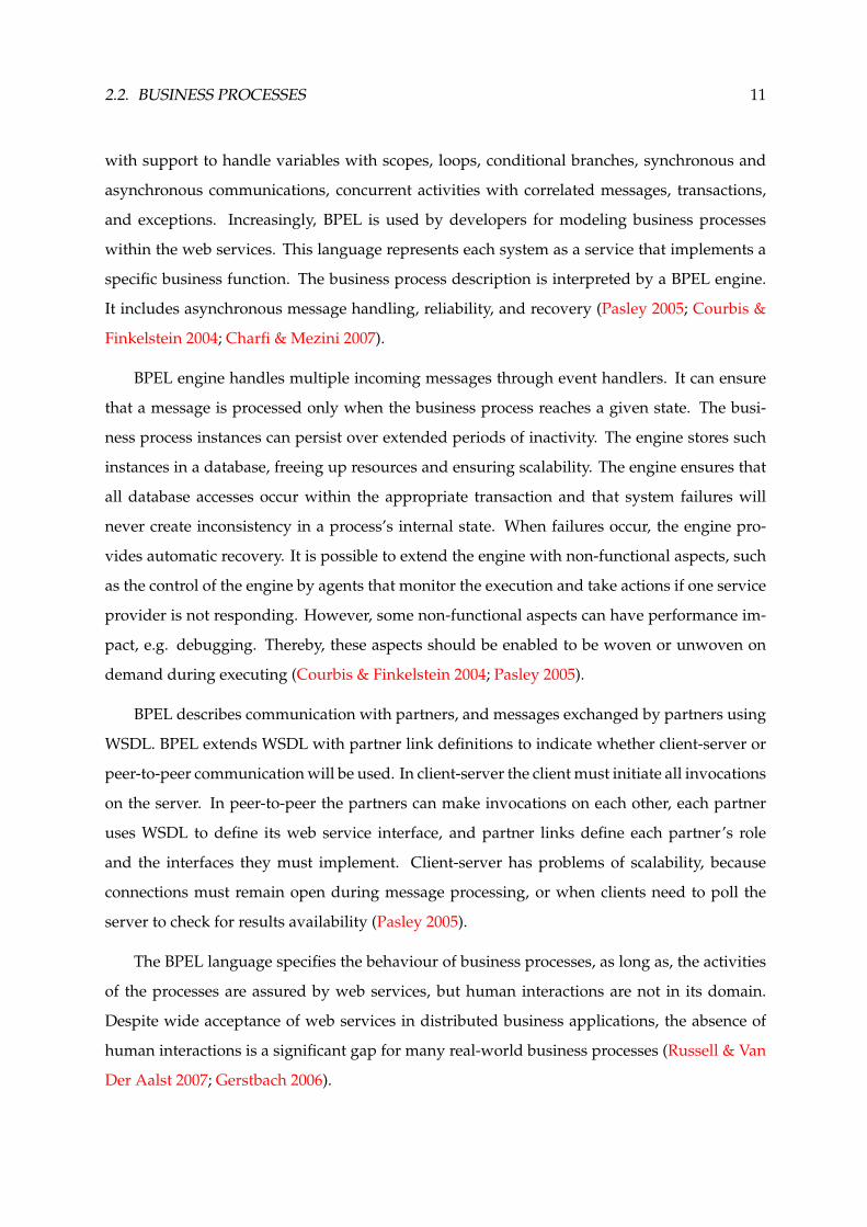
with support to handle variables with scopes, loops, conditional branches, synchronous and
asynchronous communications, concurrent activities with correlated messages, transactions,
and exceptions. Increasingly, BPEL is used by developers for modeling business processes
within the web services. This language represents each system as a service that implements a
specific business function. The business process description is interpreted by a BPEL engine.
It includes asynchronous message handling, reliability, and recovery (Pasley 2005; Courbis &
Finkelstein 2004; Charfi & Mezini 2007).
BPEL engine handles multiple incoming messages through event handlers. It can ensure
that a message is processed only when the business process reaches a given state. The busi-
ness process instances can persist over extended periods of inactivity. The engine stores such
instances in a database, freeing up resources and ensuring scalability. The engine ensures that
all database accesses occur within the appropriate transaction and that system failures will
never create inconsistency in a process’s internal state. When failures occur, the engine pro-
vides automatic recovery. It is possible to extend the engine with non-functional aspects, such
as the control of the engine by agents that monitor the execution and take actions if one service
provider is not responding. However, some non-functional aspects can have performance im-
pact, e.g. debugging. Thereby, these aspects should be enabled to be woven or unwoven on
demand during executing (Courbis & Finkelstein 2004; Pasley 2005).
BPEL describes communication with partners, and messages exchanged by partners using
WSDL. BPEL extends WSDL with partner link definitions to indicate whether client-server or
peer-to-peer communication will be used. In client-server the client must initiate all invocations
on the server. In peer-to-peer the partners can make invocations on each other, each partner
uses WSDL to define its web service interface, and partner links define each partner’s role
and the interfaces they must implement. Client-server has problems of scalability, because
connections must remain open during message processing, or when clients need to poll the
server to check for results availability (Pasley 2005).
The BPEL language specifies the behaviour of business processes, as long as, the activities
of the processes are assured by web services, but human interactions are not in its domain.
Despite wide acceptance of web services in distributed business applications, the absence of
human interactions is a significant gap for many real-world business processes (Russell & Van
Der Aalst 2007; Gerstbach 2006).

12 CHAPTER 2. STATE OF THE ART
Business Process Model and Notation (BPMN)
BPMN was developed by BPMI (Business Process Management Initiative), and it is currently
maintained by the OMG (Object Management Group) since the two organizations merged in
2005. The current version of BPMN specification is 2.0, it not only defines a standard on how to
graphically represent a business process like BPMN 1.x, but also includes execution semantics
for the elements defined, and an XML format on how to store process definitions. A process
defined with a graphical tool is a graph that describes the order in which a series of steps need
to be executed using a flow chart (Lonjon 2004). Figure 2.3 shows an example of a business
process modeling using BPMN.
Figure 2.3: Modeling of a business process using BPMN
The main purpose of business processes models generally, and BPMN models in particu-
lar, is to facilitate the communication between domain analysts and developers. Furthermore,
these models support decisions based on techniques such as cost analysis, scenario analysis,
and simulation (Ouyang et al. 2009).
JBPM9 (JBoss Business Process Management) is the open source WfMS (Workflow Man-
agement System) suited by JBoss. Initially, jBPM processes are created using a proprietary
language of process definition called jPDL (jBPM Process Definition Language). jBPM5 is the
latest version of the jBPM suite which is based on the BPMN 2.0 specification and supports the
entire life cycle of the business processes (modeling, executing, monitoring, and management)
(Koenig 2004).
9jBPM - http://www.jboss.org/jbpm/

2.2. BUSINESS PROCESSES 13
JBoss Business Process Management (jBPM)
A workflow describes the order in which a series of steps need to be executed. It is especially
useful in describing state-based and long-running processes. JBPM allows users to specify,
execute, and monitor the business processes of their organization. This suite can be integrated
into any Java application or can run standalone in a server environment (Bali 2009).
JBPM allows constructing business processes through drag and drop tools. It includes not
only standard node types like start, end, split, join, but more advanced node for incorporat-
ing wait states, timers, events, composite nodes, etc. The process model is based on simple
nodes, connections, and context that allows including new nodes types into an existing process
language, or supporting completely different languages as a whole.
BPEL and BPMN
BPMN and BPEL are two standards for specifying and executing business process models that
can be used together using some open-source tools known as BPMN2BPEL.10 It aims at trans-
lating BPMN models into BPEL processes, thereby, the BPMN models are the input of the
system, the BPMN2BPEL are the translating tools, and the BPEL is the engine for executing
business processes. However, the development of these tools has disclosed fundamental dif-
ferences between BPMN and BPEL, which make the translation very difficult, and in some
cases impossible. It is beyond the scope of this work to discuss BPMN2BPEL tools, this can be
found in an appendix of the BPMN standard specification.
Web Services Choreography Description Language (WS-CDL)
Choreography languages are a means to define the rules of collaboration between parties with-
out revealing internal operations. They allow specifying when which information is sent to
which party, and which options are available to continue the interaction. The WS-CDL is a
W3C candidate recommendation for web service composition. WS-CDL is expected to be used
in conjunction with BPEL. In this context, there are two possible scenarios (Mendling & Hafner
2005):
10BPMN2BPEL Project - http://code.google.com/p/bpmn2bpel/

14 CHAPTER 2. STATE OF THE ART
1. business entities may agree on a specific choreography defined in WS-CDL in order to
achieve a common goal. This WS-CDL choreography is then used to generate WS-BPEL
process stubs for each party;
2. business entities may want to publish its processes’ interface to business partners. In this
scenario, a choreography description of the internal process has to be generated.
WS-CDL is a declarative XML-language for the specification of collaboration protocols
based on web services. It provides a global public view on participants, collaborating in a
peer-to-peer way by offering distributed web services, in order to achieve a common business
goal. WS-CDL describes their observable behaviour through the order of the messages they
exchange as well as the operations they offer (Mendling & Hafner 2005).
Yet Another Workflow Language (YAWL)
Despite the efforts of the workflow management coalition (WfMC), workflow management
systems use a large variety of languages and concepts based on different paradigms. Some
workflow management systems are based on Petri Nets (Peterson 1977), but typically add both
product specific extensions and restrictions. Currently, most workflow languages support the
basic constructs of sequence, iteration, splits (AND and XOR) and joins (AND and XOR). How-
ever, the interpretation of even these basic constructs is not uniform and it is often unclear how
more complex requirements could be supported. Requirements can be indicated through work-
flow patterns (Van Der Aalst & Ter Hofstede 2005); ”Pattern is the abstraction from a concrete form
which keeps recurring in specific non-arbitrary contexts” (Riehle & Zullighoven 1996).
BPEL is currently the most widespread language for composing web services, but it lacks
formal semantics. YAWL11 is a new proposal of a workflow engine, which supports a concise
and powerful workflow language, and handles complex data transformations and web service
integration. YAWL defines twenty most used workflow patterns divided in six groups: basic
control-flow, advanced branching and synchronization, structural, multiple instances, state-
based, and cancellation. YAWL extends Petri Nets by introducing some workflow patterns for
multiple instances, complex synchronizations, and cancellation. Furthermore, YAWL supports
tools like editor and engine, which are freely available (Brogi & Popescu 2006).
11YAWL - http://www.yawlfoundation.org/

2.2. BUSINESS PROCESSES 15
Triana
Triana12 is a visual programming environment that allows users to compose applications from
programming components by dragging and dropping them into a workspace, and connecting
them together to build a workflow graph. It was initially developed to help in the flexible
quick-look analysis of data sets.
Today, Triana can be used by applications in a variety of ways through the use of its ”plug-
gable software architecture”. It has many of the key programming constructs such as do, while,
repeat until, if, then, etc. that can be used to graphically control the data-flow. Triana performs
dynamic run-time type checking on requested connections to ensure data compatibility be-
tween components. It is divided into a set of modularized pluggable interacting components:
GUI, Triana Controlling Service (TCS), Triana Engine, and/or other Engine (e.g. BPEL Engine)
(Taylor et al. 2003).
Triana is good for automating repetitive tasks, such as performing a find-and-replace on
all the text files in a particular directory, or continuously monitoring the spectrum of data that
comes from an experiment that runs for days or even years. It is a good tool for classroom or
teaching laboratory for simulated experimental data. Triana allows creating new features, if
the supplied with Triana are not enough. Furthermore, it provides support for error handling,
and it allows changing the parameters dynamically without interrupting the flow data.
Taverna
Taverna13 is a powerful scientific workflow management application that allows designing and
executing workflows. It provides a graphical workbench tool for both creating and running
workflows. In Taverna, a workflow is considered to be a graph of processors, each of which
transforms a set of data inputs into a set of data outputs. These workflows are represented in
the Scufl language.
Scufl language is a high-level, XML-based, conceptual language in which each processing
step of the workflow represents one atomic task. A workflow in the Scufl language consists of
three main entities (Oinn et al. 2004):
12Triana - http://www.trianacode.org/13Taverna - http://www.taverna.org.uk/
16 CHAPTER 2. STATE OF THE ART
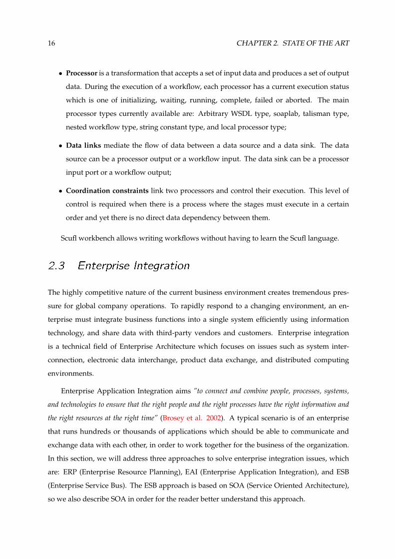
• Processor is a transformation that accepts a set of input data and produces a set of output
data. During the execution of a workflow, each processor has a current execution status
which is one of initializing, waiting, running, complete, failed or aborted. The main
processor types currently available are: Arbitrary WSDL type, soaplab, talisman type,
nested workflow type, string constant type, and local processor type;
• Data links mediate the flow of data between a data source and a data sink. The data
source can be a processor output or a workflow input. The data sink can be a processor
input port or a workflow output;
• Coordination constraints link two processors and control their execution. This level of
control is required when there is a process where the stages must execute in a certain
order and yet there is no direct data dependency between them.
Scufl workbench allows writing workflows without having to learn the Scufl language.
2.3 Enterprise Integration
The highly competitive nature of the current business environment creates tremendous pres-
sure for global company operations. To rapidly respond to a changing environment, an en-
terprise must integrate business functions into a single system efficiently using information
technology, and share data with third-party vendors and customers. Enterprise integration
is a technical field of Enterprise Architecture which focuses on issues such as system inter-
connection, electronic data interchange, product data exchange, and distributed computing
environments.
Enterprise Application Integration aims ”to connect and combine people, processes, systems,
and technologies to ensure that the right people and the right processes have the right information and
the right resources at the right time” (Brosey et al. 2002). A typical scenario is of an enterprise
that runs hundreds or thousands of applications which should be able to communicate and
exchange data with each other, in order to work together for the business of the organization.
In this section, we will address three approaches to solve enterprise integration issues, which
are: ERP (Enterprise Resource Planning), EAI (Enterprise Application Integration), and ESB
(Enterprise Service Bus). The ESB approach is based on SOA (Service Oriented Architecture),
so we also describe SOA in order for the reader better understand this approach.
2.3. ENTERPRISE INTEGRATION 17
2.3.1 Enterprise Resource Planning (ERP)
ERP was pioneering in enterprise integration software. It offers a system that accomplishes the
integration of different functions in an organization. These functions assist the businesses in
managing the important parts of the business, including product planning, parts purchasing,
maintaining inventories, interacting with suppliers, providing customer service, and tracking
orders. However, ERP has a centralized management model and it focused historically on in-
tegration of internal business functions. Moreover, when the applications interact with each
other using a point-to-point model, the maintenance costs increase and the reuse of the ap-
plications becomes more difficult (Lee et al. 2003). Hence, research was made and Enterprise
Application Integration (EAI) emerged as an alternative or supplemental technology for the
integration of internal and external business functions.
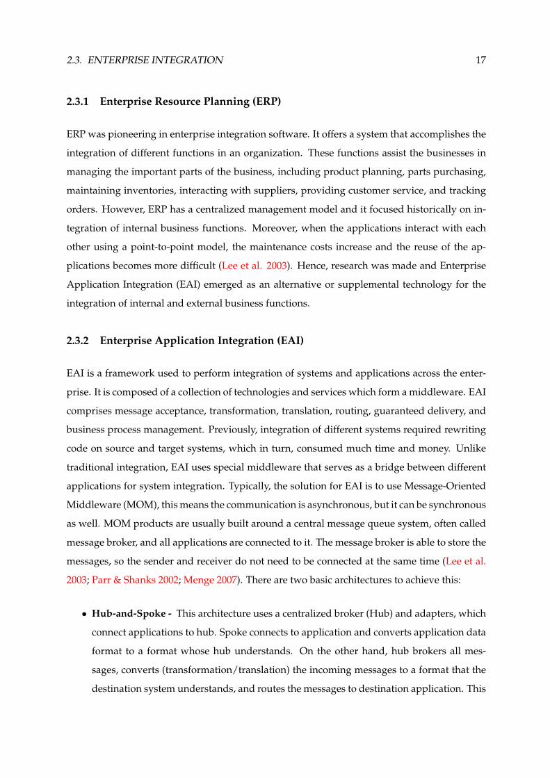
2.3.2 Enterprise Application Integration (EAI)
EAI is a framework used to perform integration of systems and applications across the enter-
prise. It is composed of a collection of technologies and services which form a middleware. EAI
comprises message acceptance, transformation, translation, routing, guaranteed delivery, and
business process management. Previously, integration of different systems required rewriting
code on source and target systems, which in turn, consumed much time and money. Unlike
traditional integration, EAI uses special middleware that serves as a bridge between different
applications for system integration. Typically, the solution for EAI is to use Message-Oriented
Middleware (MOM), this means the communication is asynchronous, but it can be synchronous
as well. MOM products are usually built around a central message queue system, often called
message broker, and all applications are connected to it. The message broker is able to store the
messages, so the sender and receiver do not need to be connected at the same time (Lee et al.
2003; Parr & Shanks 2002; Menge 2007). There are two basic architectures to achieve this:
• Hub-and-Spoke - This architecture uses a centralized broker (Hub) and adapters, which
connect applications to hub. Spoke connects to application and converts application data
format to a format whose hub understands. On the other hand, hub brokers all mes-
sages, converts (transformation/translation) the incoming messages to a format that the
destination system understands, and routes the messages to destination application. This
18 CHAPTER 2. STATE OF THE ART
architecture is easy to manage, but the scalability is a problem when the number of mes-
sages increase (Lee et al. 2003; Qureshi 2005).
• Bus - This architecture uses a central messaging backbone (Bus) for messages propaga-
tion. The applications publish messages to bus using adapters. These messages flow to
subscribing applications using the messages bus. Subscribing applications have adapters,
which take messages from bus and transform the messages into a format required for the
application. The main difference between hub and bus topology is that for the bus ar-
chitecture, the integration engine that performs messages transformation and routing is
distributed in the application adapters. Since adapters have integration engine and run
on same platform on which source and target applications run, this architecture is more
scalable, but it is more complex to manage compared to hub topology (Lee et al. 2003;
Wu & Tao 2010).
A big problem of EAI solutions is that they often use proprietary protocols, and platform
specific interfaces and deployments. This leads to a total dependency of the applications on the
infrastructure and causes interoperability problems with EAI products of alternative vendors.
As a result, islands of EAI-based infrastructures can often be found. A proprietary implemen-
tation offers a lot of functionalities, as a suite of products, and it uses some proprietary formats
to enhance the performance. However, these two features increase the cost.
2.3.3 Enterprise Service Bus (ESB)
ESB is usually based on open standards which decrease the cost. ESB is a distributed integra-
tion infrastructure that provides routing, protocol conversion, message format transformation,
accept and deliver messages from various services and applications which are linked to ESB.
Hereupon, the question on what exactly is the difference between ESB and EAI arises. Be-
yond the cost, which is significantly lower for ESB because it is based on open standards (no
more technology lock-in), the ESB was developed to support the SOA paradigm, so it has all
advantages offered by SOA (Lee et al. 2003; Menge 2007).

2.3. ENTERPRISE INTEGRATION 19
Service-Oriented Architecture (SOA)
SOA is a relatively newer form of information systems architecture and a real buzzword in the
last few years in the domain of information system development. It can be defined as ”an archi-
tecture or development style that builds on distributed, loosely coupled, and interoperable components of
software agents called services” (Kanchanavipu 2008). SOA have become increasingly important
as a paradigm for the development of distributed software systems. Thereby, the applications
are built of a set of collaborative services running in a distributed environment. Hence, it can
be considered a peer-to-peer architecture, totally distributed, with the services distributed be-
tween different resources.
The adoption of SOA may be unacceptable for some traditional enterprises because of the
lack of sufficient control over the information assets. However, SOA represents a framework
to integrate business processes and information/communication technologies in the form of
components (services). Components are reusable, interoperable, and satisfy the needs and
demands of dynamical business processes (Zalewski 2007; Geric 2010).
SOA has been developed to enhance the communication between organizations, it is a way
to provide interoperability advantage for the systems, but having different types of SOA de-
velopment architectures can still cause some interoperability problems. Therefore, seamless
interoperability is a major concern. Development of theoretical and conceptual frameworks
would be a good step toward achieving seamless interoperability in the SOA systems. Cur-
rently, researchers within this area are focusing more on the interoperability requirements, and
their works can be divided into three categories, which are (Ibrahim 2010): Individual applica-
tions; Domain specifications; Conceptual framework.
SOA solutions typically have three fundamental entities (Figure 2.4), Service Provider, Ser-
vice Consumer, and Service Registry. The service provider creates a service contract and registers
its services to a central naming server, also called service registry. A service consumer can use
this service registry to discover available services and retrieve a service contract which defines
how the service can be used and how to connect to a particular provider. Service contract is
very important to facilitate the collaboration between services, by using collaboration between
different services is possible to build a more complex system (Menge 2007).

20 CHAPTER 2. STATE OF THE ART
Figure 2.4: SOA’s Architecture
ESB and SOA
The fundamental goals of business integration are linking business systems across the enter-
prise and extending business services to customers and trading partners. If several applications
interact with each other using point-to-point model, the relation between application become
complex. This will bring high maintenance costs and make the reuse of the applications diffi-
cult. Today, enterprises need powerful integration solutions, but they want them to be based
on open standards and to support SOA. ESB is an ideal solution for such issues because it pro-
vides universal mechanism to interconnect all the services required in the business composite
solutions, without compromising security, reliability, performance, and scalability. Moreover,
ESB must coordinate the interactions of the various resources and providing transactional sup-
port. The general goal is to provide interoperability, without writing code (Menge 2007; Wu &
Tao 2010).
In order to support SOA, the ESB service containers have to support web service technolo-
gies. The open source ESB solutions are typically built on top of JMS (Java Messaging Service)
middleware systems. In addition to the runtime environment, an ESB must also provide a de-
velopment environment with tools for creating web services. Existing systems are fundamental
to the ESB because reusing rather than replacing concept. ESB provides essentially the same
functionality as the existing systems, but they are exposed as secure and reliable web services
that the organization or its business partners can reuse (Pasley 2005; Menge 2007). Typically
ESB features are:

2.3. ENTERPRISE INTEGRATION 21
• Connectors/Adapters - it is the ability of an ESB to send requests and receive responses
from integration services and integrated resources. In this point, ESB has to support sev-
eral standards, such as SOAP, WSDL, UDDI, JMS, JCA (J2EE Connector Architecture),
TCP, UDP, HTTP, SSL (Secure Sockets Layer), JBI (Java Business Integration), RMI (Re-
mote Method Invocation), JDBC (Java Database Connectivity), SMTP, POP, etc. These can
be adapters for popular application packages, such as ERP, SCM (Supply Chain Manage-
ment), and CRM (Customer Relationship Management). Using prefabricated adapters
reduces the work required to integrate applications into a SOA;
• Routing - it is the ability to decide the destination of a message during its transport. Rout-
ing services are an essential feature of an ESB because they allow decoupling the source
of a message from the ultimate destination. The common standard used for addressing is
the URI (Uniform Resource Identifier). There are several types of routers: content-based,
recipient list, splitter, aggregator, and resequencer. The different routers can be combined
to create complex message flows. All routers can be implemented as dynamic routers;
• Mediation - it refers to all transformations or translations between different resources,
including transport protocol, message format, and message content. It is very important
because applications rarely agree on a common data format. XSL (Extensible Stylesheet
Language) and XPath (XML Path Language) are powerful tools for working with XML
messages;
• Security - it is the ability to encrypt and decrypt the content of messages, authenticate,
perform access control, and assure secure persistence;
• Management - it is the ability to provide audit and logging facilities for monitoring in-
frastructure, and possibly also for controlling process execution;
• Process Orchestration - ESB may include an engine to execute business processes de-
scribed with the BPEL. This engine coordinates the collaboration of the services connected
to the bus.
2.3.4 Discussion
Table 2.1 summarizes the comparison among ERP, EAI, and ESB according to some param-
eters. The ESB and EAI are very similarly, but ESB allows building systems or applications

22 CHAPTER 2. STATE OF THE ART
more loosely coupled than EAI because ESB is based on open standards and EAI is proprietary.
Moreover, the ESB has a cost of development much smaller than EAI, by the same reasons pre-
sented above. Then, in the next section (refer to section 2.3.5), we will present some enterprise
integration solutions based on the ESB approach.
Evaluation ERP EAI Hub EAI Bus ESBParameterTopology Single/Multi Server Hub Bus BusArchitecture Centralized Centralized Decentralized DecentralizedIntegration Effort High Medium Medium LowCoupling Strongly Moderately Moderately LooselyScalability Low Medium High HighManagement Easy Easy Complex ComplexDevelopment Proprietary Proprietary Proprietary StandardCost High Medium Medium Low
Table 2.1: Comparison among ERP, EAI, and ESB
2.3.5 ESB Solutions
In this section, we present the following ESB solutions: JBoss ESB,14 Apache ServiceMix,15
OpenESB,16 and PEtALs.17 This solutions are based on JBI (Java Business Integration). At the
end of this section, we present another ESB solution, called Mule ESB.18
Java Business Integration (JBI)
JBI is an ESB specification proposed by Sun Microsystems (Oracle). It is divided into three
parts:
• Normalized Message Router (NMR) provides the mediation to allow components to
interoperate in a standard way;
• JBI Component Framework provides the pluggable infrastructure for hosting JBI com-
ponents;
14JBoss ESB - http://www.jboss.org/jbossesb15Service Mix - http://servicemix.apache.org/home.html16OpenESB - http://open-esb.org/17PEtALs - http://petals.ow2.org/18Mule - http://www.mulesoft.org/

2.3. ENTERPRISE INTEGRATION 23
• Management Module provides a set of standards based on JMX19 to manage the JBI
environment and the components themselves.
There are two kinds of components in JBI environment:
• Service Engine (SE) provides business logic and transformation services to other compo-
nents, e.g. BPEL engine;
• Binding Component (BC) provides connectivity to services external to the JBI environ-
ment, e.g. web services.
Developers can develop standard JBI components (adapters) to connect external applica-
tion systems using the ESB, and thus, they achieve interoperability between legacy systems
(Ning et al. 2008; Kruessmann et al. 2009).
JBoss ESB
JBoss ESB is the next generation of EAI, based on the SOA paradigm, and without the vendor-
locking. In the JBoss ESB, mediation is a deployment choice and not a mandatory requirement.
Thereby, JBoss ESB may perform mediation using XSLT (eXtensible Stylesheet Language for
Transformation) or Smooks Framework20 for XML and non-XML data transformation. More-
over, it provides process orchestration via BPEL or jPDL (jBPM Process Definition Language),
message encryption, and access control lists (ACLs). ACLs are important and complimentary
to security protocols. JBoss ESB has support for HTTP/HTTPS, FTP/SFTP, JMS, SOAP, UDDI,
SMTP, POP, SQL, Hibernate, JCA, Sockets, and local file system.
Monitoring and others JBoss ESB’s capabilities can be obtained by plugging in other ser-
vices or layering existing functionality on the ESB. The JBoss ESB can be seen as the fabric for
building, deploying, and managing event-driven SOA applications and systems.
Apache ServiceMix
Apache ServiceMix is the JBI implementation of the Apache Software Foundation combining
the functionality of SOA and EDA (Event-Driven Architecture) to create an agile ESB. It uses
19JMX - http://java.sun.com/javase/technologies/core/mntr-mgmt/javamanagement/20Smooks Framework - http://docs.codehaus.org/display/MILYN/Smooks
24 CHAPTER 2. STATE OF THE ART
JMS to carry the messages on the bus. The used implementation of JMS is Apache ActiveMQ.
The message queues which have been created especially for this can be monitored with JMX
Console. As it uses JMS for message exchange, the bus provides message persistence and sup-
porting for transactions. ServiceMix provides the following connectors: HTTP, FTP, JMS, SOAP,
SMTP, POP, and local file system. It allows services to be integrated through different APIs and
across different transport technologies, and it contains a number of WS-* implementations built
on JBI, such as WS Notification.
ServiceMix supports any BPEL engine, rule engine, transformation engine, scripting en-
gine, or other integration component, such as specific JBI binding components. However, it
does not content a BPEL engine, if BPEL engine is desirable it can be installed as JBI compo-
nent. The description of endpoints using WSDL is the main difference between OpenESB and
ServiceMix. Service Mix uses the Apache XMLBeans21 for the whole configuration, even ser-
vices are configured with XMLBeans. However, the more powerful option of Service Mix is
Camel22 that is a open source integration framework.
OpenESB
OpenESB was developed by an open source community under the direction of Sun Microsys-
tems (Oracle). It implements the JBI specifications and provides integration based on open
standards. OpenESB is strongly linked with the Netbeans IDE and the Glassfish Application
Server. Glassfish ESB is an Open ESB distribution that provides everything necessary for de-
veloping, installing, and running integrations solutions, supported by graphical tools.
OpenESB has a Composite Application Service Assembly (CASA) editor that provides a
graphical overview of integration applications, which are called assemblies. Furthermore, the
OpenESB has several components for data transformation, orchestration, and connectivity. It
has support for HTTP, FTP, JMS, SOAP, SQL, JDBC, and SAP23 systems. The logic layer can be
expressed in BPEL, EJB,24 and POJO (Plain Old Java Object). OpenESB needs BPEL to connect
binding components and service engines.
21XMLBeans - http://xmlbeans.apache.org/22Camel Framework - http://camel.apache.org/23SAP - http://www.sap.com/country-selector.epx24EJB - http://java.sun.com/products/ejb/

2.3. ENTERPRISE INTEGRATION 25
PEtALs
PEtALs is an open source ESB solution for large SOA architectures. PEtALs ESB is built with
and on top of agile technologies like JBI and Fractal. Fractal (Bruneton et al. 2006) is a modu-
lar and extensible component model that can be used with various programming languages to
design, implement, deploy, and reconfigure various systems and applications. On the PEtALs
point of view, all the container services, such as service registry, message router, message trans-
porter, discovery, etc., are provided by the Fractal framework.
PEtALs is not only a JBI container, it also contains tools for management, monitoring, and
to create JBI components. Moreover, the Petals offers guaranteed service delivery. Therefore,
when a service cannot be delivered, request is saved and delivered later. One other powerful
feature is the possibility to replace software components at runtime. PEtALs has connectors for
common standards: HTTP, FTP, SOAP, JMS, SMTP, POP, JDBC, POP, IMAP.
PEtALs uses BPEL for processing orchestration and XSLT for transformation. Furthermore,
it performs access control and provides quick assembly of services with EIP (Enterprise Inte-
gration Patterns), POJO, and JCA. Distributed architecture provided by the PEtALs ensures
high availability and eliminates single point of failure. Therefore, it is highly distributable and
scalable.
Mule (Menge 2007)
Mule is an open source messaging platform based on SOA. It has a service container called
UMOs (Universal Message Objects) which is highly distributable object broker. The container
uses a generic message endpoint interface to facilitate the communications between systems.
UMOs are able to connect to external applications, other UMOs, or other Mule instances.
The unified technology and independent methods of interacting with disparate resources
makes it very easy to use UMOs for the integration of applications. However, it may be neces-
sary to develop applications adapters.
The Mule provides all integration services which are essential to ESB, such as support for
transactions, transformations, routing, logging, auditing, management, security, event process-
ing, and even process orchestration using BPEL. Mule is able to handle various communication

26 CHAPTER 2. STATE OF THE ART
mechanisms, including HTTP, FTP, TCP, UDP, JMS, SOAP, SMTP, POP, IMAP, JDBC, RMI, and
others.
Mule was designed for fast development of distributed network, and it is highly scalable,
lightweight, fast, and simple to adopt. An important principle of an ESB is to use as much
declaration and configuration as possible, and avoid writing code. Therefore, Mule uses a
XML configuration file in which the connectors, routers, transformers, message endpoints, and
UMOs are declared.
Discussion
As stated before, this work aims to develop a platform interoperable with some collabora-
tion platform, and so, it should be possible to govern collaborative sessions using business
processes. The ESB approach arose in order to keep the interoperability between enterprise ap-
plications. To close this section, we will make a discussion about the ESB solutions presented
above (Table 2.2).
Evaluation JBoss ESB ServiceMix OpenESB PEtALs MuleParameterTopology Centralized Centralized Centralized Centralized or Centralized or
Distributed DistributedRouting Content-based Splitter; Content-based; Filter;
Aggregator; Priority-based Aggregator;Content-based Resequencer;
Content-basedMediation XSLT; Smooks XSLT; Spring XSLT XSLT XSLTScalability No No No Yes YesSecurity Yes No No Yes YesManagement No Yes No Yes YesOrchestration BPEL; jPDL BPEL; Camel BPEL BPEL BPELChoreography No No No No No
Table 2.2: Classification of the ESB Solutions
According to the Table 2, it can be seen the presented solutions are very similar. However,
scalability is an important requirement, so the PEtALs and Mule solution are more suitable to
enforce this requirement. Mule is the most popular open source ESB, so it has more documen-
tation available than the PEtALs. Furthermore, it was adopted by large enterprises like Google,
Cisco, Amazon, etc.

2.4. SUMMARY 27
2.4 Summary
In this chapter, we did an extensive survey in topics and available technologies that we deter-
mined as essential for the conception and development of our own solution.
As the objective of this work is to develop a graphical application cross-platform and ac-
cording to the Web 2.0 principles to update the state of the business processes , we started by
the study of some technologies used in the development of the web applications (refer to sec-
tion 2.1). Moreover, since the web application (client) needs to communicate with servers, so
we also survey some technologies to perform this requirement. The technologies approached
were: AJAX; JSON; REST; Web Services; Widgets.
The MBC platform provides the general functions of a workflow system, which are the
modeling and execution of business processes. Thereby, we survey some standards, as well as
some workflow systems, that have been adopted by industry (refer to section 2.2).
BPEL is the proposed standard language to achieve the web services orchestration. On the
other hand, the main purpose of the BPMN is to facilitate the communication between domain
analysts and developers.
JBPM 5 is the latest version of the jBPM suited by JBoss Community. This suite is based
on the BPMN 2.0 specifications and supports the entire life cycle of the business processes
(modeling, executing, monitoring, and management).
The proposed solution comprises several entities. Therefore, we make an extensive survey
about enterprise application integration (refer to section 2.3). The best solutions are based on
web services (SOA) and provide several features. However, these solutions are a little complex.

28 CHAPTER 2. STATE OF THE ART

3Solution's Architecture
The objective of this chapter is to present the architectural design model of our solution. In
the state of the art chapter (refer to chapter 2), we did an extensive survey of the concepts
and challenges about web applications, business processes, and enterprise integration. Hence,
our solution’s architecture leverages the insights and experiences of the studied concepts and
the tools that have been applied. The solution’s architecture overview is comprised by several
entities, which are depicted in Figure 3.1:
Figure 3.1: Architecture Overview
• ESB is the communication channel between the several entities and it is responsible for
the interoperability between them. This entity is based on a ESB architecture;
• MBC Platform is the main entity of this work. It provides several functionalities and
includes a business process suite to support the entire life cycle of business processes;
• Knowledge Repository stores the business processes of the organization, and it allows
the collaborative modeling of business processes;

30 CHAPTER 3. SOLUTION’S ARCHITECTURE
• PUC Platform is the collaboration platform developed by PT Inovacao. Our solution as-
sumes that the core groupware functionality is hereby deployed;
• PUC Gateway acts as a proxy server for the mobile terminals, mediating access to the
provided core collaborative functionality residing in PUC;
• External System represents, for instance, a legacy application that the organization wants
to continue to use while adding or migrating to a new set of applications.
We also developed a Web Application which is employed by users to activate and update
the business processes. However, the business processes can also be activated and updated by
external systems (entities).
Hereupon, the proposed architectural design is focused on fulfilling the following non-
functional requirements:
• Scalability: the proposed solution already offers a good performance for heavier loads.
However, the system can be easily modified to accommodate even heavier loads by, for
instance, changing the database software;
• Extensibility: we use an object oriented design in both server and client-side architec-
tures that is easily extended with new components. Moreover, we use a multi-tier archi-
tecture that provides a model for developers to create flexible and reusable applications;
• Interoperability: all entities are connect through a central bus based on a ESB architecture
that allows to easily connect new entities. The interoperability is achieved through some
formats conversation, however, it is necessary ensure that there is no incompatibility of
features;
• Data Persistence: the proposed solution allows storing the data in an external database.
Thus, it is possible to recover the system from some errors, for instance, system crash.
Furthermore, the system consumes less memory since it only needs to have part of the
data loaded in the memory;
• Lightweight Application: we develop a web application that invokes web services based
on the REST architectural style which is the most lightweight alternative.

3.1. PUC’S ARCHITECTURE 31
As the reader may recall from this document’s introduction (refer to chapter 1), one of the
goals of this work is to integrate our MBC platform with the collaborative platform developed
by PT Inovacao, called PUC. This collaborative platform already accomplishes access control,
concurrency and session management requirements, and offers a persistent information base.
It also provides a core of collaborative functionality through a set of application interfaces and
resource management controllers. By integrating our solution with the PUC, we gain immedi-
ate support to create, manage, and control collaborative sessions using business processes.
The architectural choices and development of PUC is not in this work’s scope. Never-
theless, we present a brief overview of PUC’s architecture, in Section 3.1, in order for the
reader better understand some of the choices made in our design. Likewise, we present a
brief overview of the Knowledge Repository’s architecture, in Section 3.2. In Section 3.3, we
present the ESB’s architecture. Next, in Section 3.4, we present MBC’s architecture with a sin-
gle detailed analysis for each component.
3.1 PUC's Architecture
PUC is born from the need of converging different collaboration services that were once sep-
arated and part of different and non interoperable platforms. PUC aims to solve this issue by
providing an abstract and unified framework of collaboration service enablers to third party
applications. The framework presents itself as a layered architecture (Figure 3.2):
• Application layer: in-house or third-party applications that want to use PUC’s service
enablers through the framework’s public API (Application Programming Interface);
• Management layer: provides the core business logic of the available collaboration ser-
vices (conversation and session management, management of collaborative resources,
etc.);
• Persistence layer: contains the necessary code for database management. It runs as a
service accessed by the manager components;
• Resource layer: holds the resource connectors which are responsible for establishing a
network connection with the resource servers while abstracting their own network pro-
tocols from the resource manager’s business logic.

32 CHAPTER 3. SOLUTION’S ARCHITECTURE
Figure 3.2: PUC’s Architecture
There is a Broker Connector component that connects to a message delivery service which
publicizes the received events launched by the platform in order to be consumed by client
applications.
The PUC Gateway depicted in Figure 3.1 acts as a proxy server for the terminals, medi-
ating access to the provided core collaborative functionality residing in PUC. This entity was
developed by Joao Sousa, a previous IST MSc student.
The unified public API, the extensible core, and the resource layers allow new resource
servers, with new network protocols, that can be added with minimal impact for the platform
developer and no cost for the client application developer.

3.2. KR’S ARCHITECTURE 33
3.2 KR's Architecture
Knowledge Repository (KR) stores the business processes of the organization. Thereby, it is
possible for a partner to get a business process from another partner, and it is also possible
to reuse business processes in different scopes. Moreover, it allows some collaboration in the
modeling of the business processes through of a business process graphical editor.
In order to store the business processes, we use the Drools Guvnor1 that is a centralised
knowledge repository developed and maintained by JBoss Community.2 The Guvnor provides
a rich web-based GUI (Graphical User Interface) that allows managing the knowledge base.
Moreover, it can be integrated with the Oryx editor which allows modeling business processes
that are stored in the repository. Oryx3 is a web-based editor for modeling business processes
hosted at Google Code. When the user opens a resource with extension .bpmn, the repository
loads the Oryx widget.
The changes in the business processes are saved in the repository which provides a ver-
sion control system. When a user is editing a resource (business process), Guvnor locks this
resource, and thus, it does not allow that other users edit the same resource at the same time.
Guvnor uses the Apache Jackrabbit,4 which is a fully implementation of the Content Repository
for Java Technology API (JCR, specified in JSR 1705 and 283).6
Guvnor is deployed as a WAR (Web Application Archive) into an application server, which
provides user interfaces over the web (REST API). Figure 3.3 shows the major components of
the knowledge repository’s architecture.
3.3 ESB's Architecture
ESB is the communication channel between the several systems. It receives the data from one
system, if necessary it performs some mediating, and then it delivers information to the target
system. Thus, the interoperability is achieved through some format conversion, however, it
1Drools Guvnor - http://www.jboss.org/drools/drools-guvnor.html2JBoss Community - http://community.jboss.org/3Oryx editor - http://code.google.com/p/oryx-editor/4 Jackrabbit - http://jackrabbit.apache.org/5JSR 170 - http://www.jcp.org/en/jsr/detail?id=1706JSR 283 - http://jcp.org/en/jsr/detail?id=283

34 CHAPTER 3. SOLUTION’S ARCHITECTURE
Figure 3.3: Knowledge Repository’s Architecture
is necessary to ensure that there is no incompatibility of features. This entity provides three
types of connectors: EJB Connector; WS Connector; REST Connector. The involved systems
in the communication process can use different connectors, for instance, system A can use EJB
Connector to send and receive information from the bus, and likewise system B can use the WS
Connector to perform the same operations, thus the system A and B can communicate with
each other despite they use different communications ways. Figure 3.4 shows an example of
the communication process between the MBC and PUC platform.
Figure 3.4: Communication process using the ESB
ESB comprises two components, Connector and Adapter (Figure 3.5). The Connector is
used to get an interface to communicate with the target system. On the other hand, the connec-
tor uses the Adapter to perform some mediation before it sends the data to the other connector.
As stated before, we provide only three types of connectors because our solution just needs
these types. We do not use an existing implementation of ESB because this entity is quite sim-
ple for the scope of this work, and the existing implementations are quite complex which are
used in other contexts.

3.4. MBC’S ARCHITECTURE 35
Figure 3.5: ESB’s Architecture
3.4 MBC's Architecture
The MBC (Mobile Business Collaboration) platform provides a web application which can be
used by users to update the business processes. Moreover, it also provides web services which
can be used by external systems. The actual activation of business processes is carried out by
the workflow engine which is provided by the jBPM suite.
The choice of jBPM suite is due to its extensive functionality and great support offered by
developers and community. Another reason is due to PT Inovacao’s long history of JBoss suites
usage, of which we can take benefit from.
MBC platform uses a knowledge agent to get processes from the repository. If a process is
already loaded in the knowledge base, it is not necessary get it from the repository, unless its
version has changed.
Furthermore, the proposed solution uses an external database to assure the persistence of
the data, and it uses external resources to send notifications to the users, such as the email
resource.
The solution’s architecture proposed (Figure 3.6) comprises four layers, which are: Domain
Layer; Business Layer; Service Layer; Presentation Layer. Each layer also comprises one or
more components. A multi-tier application architecture provides a model for developers to
create flexible and reusable applications.

36 CHAPTER 3. SOLUTION’S ARCHITECTURE
Figure 3.6: MBC’s Architecture
3.4.1 Presentation Layer
The top-most level of the application is the graphical user interface (Client Component). The
main function of the Client Component is to translate tasks and results into something the
users can understand. For instance, the users can choose and start a business process using the
available interface. The Client Component’s architecture is depicted in Figure 3.7.
Figure 3.7: Client Component’s Architecture
3.4.2 Service Layer
The service layer comprises three components: Servlets; Web Services; Service Enablers. The
main function of this layer is to explore the business layer functionalities.

3.4. MBC’S ARCHITECTURE 37
Servlets
The servlets provides a REST API which is used by the client component to perform user re-
quests. Each servlet has a specific business tasks associated. However, there is one servlet to
perform generic business tasks. The available servlets are:
• User Servlet: to get, create, update, and delete users;
• Process Servlet: to get, create, update, and delete processes;
• Human Task Servlet: to get, create, update, and delete human tasks;
• Web Services Servlet: to perform generic business tasks, for instance, the Sign-in Service.
Web Services
This component implements the API provided through the WSDL contract. All available ser-
vices defined in the WSDL contract must be implemented by this component. When an entity
invokes the MBC’s web services using the HTTP and SOAP technology, this component re-
ceives the request, performs the service, and finally sends the answer to the caller entity.
Service Enablers
The Service Enablers implement the services in order to explore the core functionalities. They
move and process data between the two surrounding layers (presentation and business layer).
In order to mask domain objects in an external representation, this component uses the DTO
(Data Transfer Object) design pattern to transfer the data from business layer to external entities
as well as to the presentation layer. The DTOs do not have any behaviour except for storage
and retrieval of its own data (selectors and getters), and furthermore they are objects that can
be serialized. Hence, we expose only the necessary information of each domain object, for
instance, the User DTO does not have the password field for security reasons.
3.4.3 Business Layer
The business layer is the main layer of the MBC platform. It comprises four components: KBase
Manager; Event Listener; Node Handler; Business Process Engine.
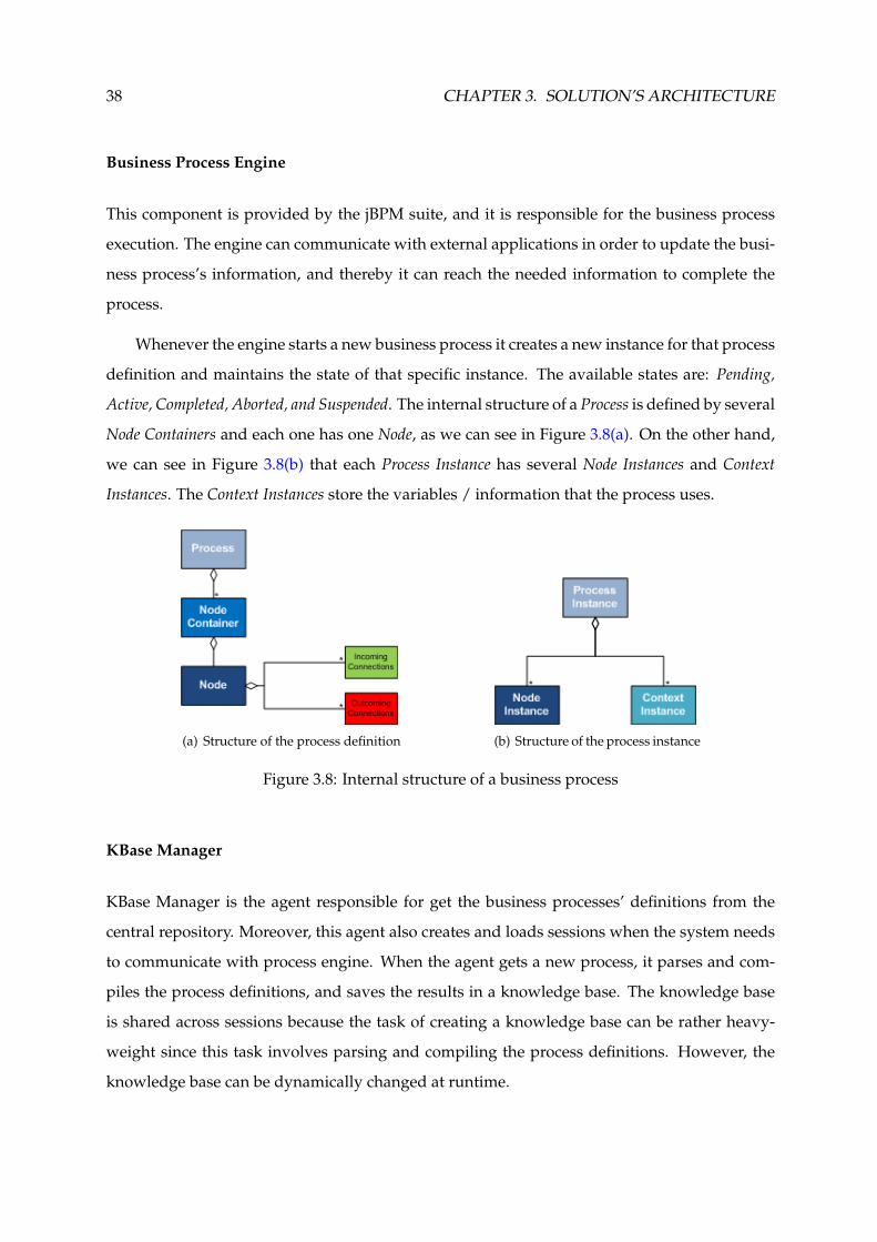
38 CHAPTER 3. SOLUTION’S ARCHITECTURE
Business Process Engine
This component is provided by the jBPM suite, and it is responsible for the business process
execution. The engine can communicate with external applications in order to update the busi-
ness process’s information, and thereby it can reach the needed information to complete the
process.
Whenever the engine starts a new business process it creates a new instance for that process
definition and maintains the state of that specific instance. The available states are: Pending,
Active, Completed, Aborted, and Suspended. The internal structure of a Process is defined by several
Node Containers and each one has one Node, as we can see in Figure 3.8(a). On the other hand,
we can see in Figure 3.8(b) that each Process Instance has several Node Instances and Context
Instances. The Context Instances store the variables / information that the process uses.
(a) Structure of the process definition (b) Structure of the process instance
Figure 3.8: Internal structure of a business process
KBase Manager
KBase Manager is the agent responsible for get the business processes’ definitions from the
central repository. Moreover, this agent also creates and loads sessions when the system needs
to communicate with process engine. When the agent gets a new process, it parses and com-
piles the process definitions, and saves the results in a knowledge base. The knowledge base
is shared across sessions because the task of creating a knowledge base can be rather heavy-
weight since this task involves parsing and compiling the process definitions. However, the
knowledge base can be dynamically changed at runtime.

3.4. MBC’S ARCHITECTURE 39
A new session is created only when the business process is started. We decided to create
a new session for each process instance, but we could use the same session for all instances.
Multiple sessions allow us to have multiple independent processing units, and it also allows
the system more scalability.
KBase Manager is used to look up the business process definitions whenever necessary.
When a process is loaded into the knowledge base, the agent assigns it a validity period.
Thus, when the validity period expires, the agent retrieves the business process from repos-
itory again, but only when a new request is received. The validity period aims to improve the
performance when the system receives a lot of requests to start the same business process at
the same time. However, the business processes can be updated at any time. Hence, to reflect
this change in the new requests, the system has to load again the business process definitions
into the knowledge base (after the expiration of validity period).
Event Listener
The jBPM suite provides methods for registering and removing listeners. A listener can be used
to listen for process-related events, like starting or completing a business process, entering and
leaving a node, etc. An event object provides access to related information, like the process in-
stance and node instance. The Event Listener component just receives the events and processes
it. At the moment, we use this component to remove unused objects from the database, when
process instance ends.
Node Handler
The domain-specific tasks are targeted to one particular application domain. However, we
proposed the development of work items that can be used across domains. For instance, we
develop a work item (ApproverNode) that approves some deal or management decision, which
can be used in several domains performing some customization. All work items are driven
according to the fluxogram in Figure 3.9. So, the work item has at least two stages, First and
Last. Basically, in the first stage we read the work item parameters (input data), and in the
last state we write the results (output data) in the database. In the last stage, we also send the
Complete Command to the business process engine. All other stages are specific and optional for
each work item.

40 CHAPTER 3. SOLUTION’S ARCHITECTURE
Figure 3.9: Execution flow of a work item
All work items have the same Node Handler associated. The Node Handler is responsible
for selecting the appropriated service for the running work item. On the other hand, the service
is responsible for the implementation of the functionalities provided by the work item. When
the service completes the task, the work item is completed, so the service sends this information
to the engine. The engine goes to the next node. If there is no next node, the business process
ends. The execution flow of a business process is depicted in Figure 3.10. The work item service
can send commands to engine, such as Complete and Abort.
The work item services can be implemented in the core, or they can be implemented in an
external system. Thus, it is possible change the service implementation without requiring the
updating of the MBC platform core. Hence, we can use different work item services depending
on the context. Moreover, decoupling the execution of work items from the process itself allows
process definition to be more declarative. In Section 3.5, we will describe the developed work
items as well as the location of the services’ implementation.

3.4. MBC’S ARCHITECTURE 41
Figure 3.10: Execution flow of a business process
3.4.4 Domain Layer
The down-most level of the application is the Data Manager. The main function of the Data
Manager is to ensure the persistence of the process instances as well as of all data required by
the system. This component loads/stores data from/in the database, whenever necessary.
We use the DAO (Data Access Object) design pattern to access to data from database. The
DAO design pattern provides a technique for separating object persistence and data access
logic from any particular persistence mechanism or API. There are clear benefits to this ap-
proach from an architectural perspective. The DAO design pattern approach provides flex-

42 CHAPTER 3. SOLUTION’S ARCHITECTURE
ibility to change an application’s persistence mechanism over time, without the need to re-
engineer application logic that interacts with the DAO tier. The DAO design pattern also pro-
vides a simple and consistent API for data access that does not require knowledge of JDBC,
EJB, or Hibernate interfaces.
3.4.5 Notifier
This component is used to send notifications to the users. We only developed the Email Notifier
which sends emails. However, this component can be easily updated to support other notifiers,
for instance, a SMS (Short Message Service) Notifier.
3.5 Prototypical Examples
As stated before, we developed work items that can be used across domains. Work items
represent atomic units of work that need to be executed. These nodes specify the work that
should be executed in the context of a process in a declarative way, specifying what should be
executed (and not how) on a higher level (no code) and hiding implementation details. Table
3.1 shows the developed work items as well as the location of the services’ implementation.
Work Item Name Service’s ImplementationApproverNode MBC (core)SelectUserNode MBC (core)SelectFeatureNode MBC (core)PUCNode PUC (resource)WSNode ESB
Table 3.1: Developed Work Items
ApproverNode - This node approves some deal or management decision, for which is nec-
essary a rate of positive votes. The participants have different vote weight according to
the its privilege level. If the rate of positive votes is equal or greater than a selected rate,
the work item goes to next stage. Otherwise, the business process is aborted after the
total weight of negative votes is found that prevents deal approvement. At each stage,
the users receive a notification using, for instance, the email resource. The purpose of
the notification is alert the users that they have a pending task in the MBC portal (web
application). When a business process is aborted, the actors (users) receive a notification

3.5. PROTOTYPICAL EXAMPLES 43
informing them that the task was cancelled. If the actors of some stage do not answer to
notification, the system resends another notification (repeats the stage). The system tries
N times and then, if the work item does not have yet the necessary information so it can
go to the next stage, the process is aborted.
SelectUserNode - The purpose of this node is to create a list of users (participants), which
can be used by the other work items of the same process. At each stage, the users also
receive a notification. The flow of execution is very similar to the ApproverNode. Unlike
the ApproverNode, SelectUserNode typically is used to gather the list of participants and
save it in the database. Hence, in this situation a business process must have more than
one work item.
SelectFeatureNode - The purpose of this node is to create a list of features, which can be used
by other work items of the same process. At each stage, the users also receive a notifi-
cation. The flow of execution is also very similar to the ApproverNode. Again, unlike the
ApproverNode, SelectFeatureNode typically is used to gather the list of features and save
it in the database. Hence, in this situation a business process must have more than one
work item.
PUCNode - This work item has a flow of execution very similar to the previous work items.
The purpose of this node is to schedule a session in the PUC platform. If the work item
opens a session successfully in the PUC platform, it completes the job. Otherwise, it
aborts the process. The session is open at the specified date. At each stage, the users also
receive a notification.
WSNode - This node is used for web services composition. Basically, we use this work item
to invoke web services deployed elsewhere. This work item can save and share data
with other work items of the same process. Thus, it is possible to use the results of the
invocation of a web service, as input data for invocation of another web service. The
purpose of this work item, in this project, is to open a session in the PUC platform using
the web services composition.

44 CHAPTER 3. SOLUTION’S ARCHITECTURE
3.6 Summary
During the course of this chapter, we have presented the architectural overview of all entities of
the proposed solution (Figure 3.1). We have also detailed each entity component individually,
starting with PUC platform (refer to section 3.1), following for the Knowledge Repository (refer
to section 3.2), and then the ESB (refer to section 3.3). Finally, we presented the MBC platform’s
components, with a single detailed analysis for each one (refer to section 3.4).
The proposed architectural design is focused on offering: Scalability; Extensibility; Interoper-
ability; Data Persistence; Lightweight Application.
All of our architectural designs follow a layered design that properly makes use of already
available third-party solutions in order to support the above mentioned requirements.
Concerning the work items (refer to section 3.5), we proposed the development of work
items that can be used across domains, performing some customization. Each work item has a
service which is responsible for the implementation of the functionalities provided by the node.
Hence, changes in the domain can be implemented by adapting the work item service. We de-
veloped the following work items: ApproverNode; SelectUserNode; SelectFeatureNode; PUCNode;
WSNode.
All the hereby described components were designed with the intent of promoting a good
implementation that properly fulfils the accomplishment of the above mentioned requirements.
In the next chapter, we will describe the implementation details and challenges.

4Solution's Implementation
In the previous section, we presented the architectural design model of our solution which is
composed by multiple and loosely coupled entities, each one with in-house developed and
third party components. Now, we will be delving in the description of our development pro-
cess and followed implementation models, in order to turn our earlier proposed design from a
concept into a coherent software implementation.
Several practises have been followed in order to minimise effort and development time,
such as:
• Incremental approach: by favouring a bottom-up development process that guaran-
tees that components which serve another are completed first in an incremental fashion
(Braude & Bernstein 2011);
• Safeguard extensibility: by always guaranteeing that new components can be easily
added to our implementation on every development phase;
• Do not reinvent the wheel: by leveraging available technologies for the development of
our solution. Preferably, technologies that are widely used today.
Object Oriented programming is a widely followed model in PT Inovacao of which its in-
house development teams have a solid knowledge base. Therefore, in order to exploit this
knowledge base and comply with the above mentioned practises, we use a Java based object
oriented implementation.
Putting this matter aside, we are now in position to present this chapter’s roadmap, which
starts by describing the technological tools that we chose to support our own in-house devel-
oped components (refer to section 4.1). The reader can refer to the implementation details of
the MBC platform’s components, in sections: 4.2.1 for the web module implementation; 4.2.2
for core module implementation, and finally 4.2.3 for the notifier module implementation.
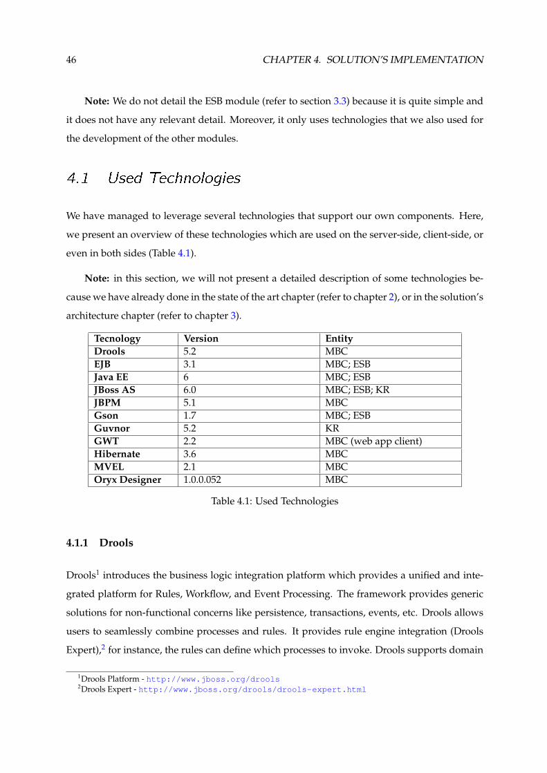
46 CHAPTER 4. SOLUTION’S IMPLEMENTATION
Note: We do not detail the ESB module (refer to section 3.3) because it is quite simple and
it does not have any relevant detail. Moreover, it only uses technologies that we also used for
the development of the other modules.
4.1 Used Technologies
We have managed to leverage several technologies that support our own components. Here,
we present an overview of these technologies which are used on the server-side, client-side, or
even in both sides (Table 4.1).
Note: in this section, we will not present a detailed description of some technologies be-
cause we have already done in the state of the art chapter (refer to chapter 2), or in the solution’s
architecture chapter (refer to chapter 3).
Tecnology Version EntityDrools 5.2 MBCEJB 3.1 MBC; ESBJava EE 6 MBC; ESBJBoss AS 6.0 MBC; ESB; KRJBPM 5.1 MBCGson 1.7 MBC; ESBGuvnor 5.2 KRGWT 2.2 MBC (web app client)Hibernate 3.6 MBCMVEL 2.1 MBCOryx Designer 1.0.0.052 MBC
Table 4.1: Used Technologies
4.1.1 Drools
Drools1 introduces the business logic integration platform which provides a unified and inte-
grated platform for Rules, Workflow, and Event Processing. The framework provides generic
solutions for non-functional concerns like persistence, transactions, events, etc. Drools allows
users to seamlessly combine processes and rules. It provides rule engine integration (Drools
Expert),2 for instance, the rules can define which processes to invoke. Drools supports domain
1Drools Platform - http://www.jboss.org/drools2Drools Expert - http://www.jboss.org/drools/drools-expert.html

4.1. USED TECHNOLOGIES 47
specific tasks inside processes using a special node that represents this interaction. This node
allows process designers to define the type of task, the actor(s), the data associated with each
task, etc.
4.1.2 Java EE and JBoss AS
Java EE or Java Platform Enterprise Edition3 is a platform whose objective is to reduce the
development complexity of enterprise oriented Java applications, by providing an extensive
set of APIs to developers that wish to deploy distributed and modular multi-tier services.
The platform’s version 6.0 (Java EE 6) focused on offering easier application development
by improving some of the features introduced in previous versions, for instance, by providing
annotations that ease the definition of web services. Applications developed with Java EE are
supported by an Application Server (AS) which is responsible for hosting and executing the
several modules of which they are composed of.
For the development of our server-side implementation, we chose JBoss AS.4 It is an open-
source implementation developed by Red Hat. Our choice is due to its extensive functionality
and great support offered by developers and community. Another reason is due to PT In-
ovacao’s long history of JBoss AS usage, of which we can take benefit from.
4.1.3 EJB
Enterprise Java Bean (EJB) is the Java EE server-side component that runs inside the EJB con-
tainer and encapsulates the business logic of enterprise applications. These applications in-
volve large number of data accessing concurrently by many users.
EJB technology is used to perform various types of task, such as: interacting with client,
maintaining session for the clients retrieving and holding data which are stored in a database,
and communicating with server. It provides two types of interfaces, Local and Remote.
Local interface is used to make local connections (inside the same JVM - Java Virtual Machine);
Remote interface is used to make remote connections (RMI - Remote Method Invocation).
3Java EE - http://www.oracle.com/technetwork/java/javaee/overview/index.html4JBoss AS - http://www.jboss.org/jbossas

48 CHAPTER 4. SOLUTION’S IMPLEMENTATION
There are several types of enterprise beans: Session; Singleton; Entity; Message. However,
we only use the Session and Singleton.
Session bean is the enterprise bean that directly interacts with the user and contains the
business logic of the enterprise application. A session bean can neither be shared nor can
persist its value (means its value cannot be saved to the database). A session bean can have
only one client. As long as the client terminates, session bean associated with this client is also
terminated and the data associated with this bean is also destroyed. Session beans are divided
into two types, Stateless and Stateful.
Stateless session bean does not maintain a conversational state with the client. When a client
invokes the methods of a stateless bean, the instance of bean variables may contain a
state specific to that client only for the duration of a method invocation. The life cycle of
a stateless bean is depicted in Figure 4.1(a);
Stateful session bean retains its state across multiple method invocations made by the same
client. If the stateful session bean’s state is changed during a method invocation, then
that state will be available to the same client on the following invocation. The life cycle
of a stateful bean is depicted in Figure 4.1(b).
(a) Life cycle of a stateless session bean (b) Life cycle of a stateful session bean
Figure 4.1: Life cycle of a EJB
Singleton bean means that the container has only one instance for this bean which can be
invoked concurrently by multiple threads, like a servlet. It supports two modes of concurrent
access, Container-Managed Concurrency and Bean-Managed Concurrency.
Bean-Managed Concurrency means that the container sends all invocations into the bean and
lets the singleton bean instance decide how and when to synchronize access;

4.1. USED TECHNOLOGIES 49
Container-Managed Concurrency means that the container will enforce concurrency via lock-
ing method access to the bean. Two modes, called locks, exist and can be assigned to both
the bean class and methods of the bean class.
Write lock means that the caller holds an exclusive lock on the bean for the duration of
the method call and all other threads for that or any other method must wait;
Read lock means that all callers have full concurrent access to the methods.
Over again, we use this technology due to PT Inovacao’s long history of EJB usage, of which
we can take benefit from. Furthermore the EJB technology is widely used for developing large
and distributed applications because it simplifies the development process once the developer
only has to concentrate on solving the problem.
4.1.4 Gson
Gson is a Java library that can be used to convert Java objects into their JSON representation. It
can also be used to convert a JSON string to an equivalent Java object. This library provides a
set of tools. However, we only use three of these tools in our implementation, namely:
• Serializer: serializes Java objects to a JSON representation. All original data structures
are maintained in the text representation;
• Deserializer: deserializes the JSON string into a Java object of the specified type. All
original data are recovered;
• Parser: parses JSON strings into a parse tree of JsonElements (JsonArray, JsonPrimitive, etc.)
Java object migration is essential to standardise our data model in both client and server
implementations. By using Gson tools we instantly convert Java objects from server to client,
or JavaScript objects to Java objects while automatically complying with a uniform data model
on both sides.
Furthermore, we also use JSON to represent some data of the domain objects. For instance,
ServiceNode object has two fields, Parameters and Results. We use a JSON representation to store
the data of these fields in the database. So, we achieve a standardised and generic model to
persist the data. Hence, the external systems can use the same ServiceNode (work item) to store
different data types using a specific implementation of the work item’s service.

50 CHAPTER 4. SOLUTION’S IMPLEMENTATION
4.1.5 GWT
Google Web Toolkit (GWT)5 is a toolkit for building complex web applications. Its main ad-
vantage is to allow us write AJAX applications in Java and then compile the produced source
code to a highly optimised JavaScript that runs across all modern desktop browsers, including
even, some mobile browsers.
GWT also makes the interaction with handwritten JavaScript possible by using its Java
Script Native Interface (JSNI). Hereby, we use overlay types to convert JavaScript objects into
Java objects.
In order to support communication with back-end servers in its applications, GWT also
provides the GWT RPC Framework that transparently makes calls to GWT Java servlets through
a customised RPC protocol, and takes care of object serialisation and other details. However,
we retrieve JSON data via HTTP, using a REST style architecture because this communication
way is the most lightweight and interoperable alternative.
4.1.6 Hibernate
Hibernate is an open-source Java persistence framework which aims to store an object oriented
data graph, built in Java, into a relational database. In the genesis of such tools is the difference
between the relational paradigm (used by most database management systems) and object-
oriented (used by Java applications), and the need to establish a correspondence between the
two data models (object / relational mapping). This mapping is then used by Hibernate to
support reading and writing of persistent objects within a unit of work.
A unit of work records all transactions of a business transaction that can affect the database
and ensures atomicity. When a unit of work ends successfully, the transactions recorded are
propagated to the database. If the unit of work aborted, all transactions recorded are discarded,
as if the unit of work had never existed. Only the operations within an active unit of work are
performed in the context of a database transaction.
Hibernate Entity Manager implements the programming interfaces and lifecycle rules as
defined by the JPA (Java Persistence API) 2.0 specification. Together with Hibernate Annotations,
5GWT Overview - http://code.google.com/intl/pt-PT/webtoolkit/overview.html

4.2. MBC PLATFORM 51
this wrapper implements a complete JPA persistence solution on top of the mature Hibernate
Core. The Entity Manager API is used to access a database in a particular unit of work. It is used
to create and remove persistent entity instances, to find entities by their primary key, and to
query over all entities.
4.1.7 MVEL
MVEL6 (MVFLEX Expression Language) is a powerful expression language for Java-based ap-
plications. The expression language is a scripting language which allows easier access to Java
components. This turns the development easier for web-content designers who have little or
practically no knowledge of the core Java Language. MVEL is typically used for exposing basic
logic to end-users and programmers through configuration such as XML files, JSON files, or
annotations.
JBPM suite uses MVEL to read the metadata of the work items once the MVEL allows us
to do more advanced configuration files. The files are defined using the JSON representation,
as we will see ahead.
4.2 MBC Platform
In this section, we present all the relevant implementation details of the MBC platform. The
MBC platform implementation was divided in three modules (Figure 3.6), which are: Web Ap-
plication Module; Core Module; Notifier Module. We begin by addressing the web application
module (refer to section 4.2.1), and then the core module (refer to section 4.2.2). At the end of
this section, we will describe the notifier module (refer to section 4.2.3).
4.2.1 Web Application Module
As seen before, the MBC platform provides a web-based GUI which allows users to interact
with the system. The module responsible by this implementation is called Web Application,
which is divided in three packages (Figure 4.2): Client; Server; Shared.
6MVEL Project - http://mvel.codehaus.org/

52 CHAPTER 4. SOLUTION’S IMPLEMENTATION
Figure 4.2: Web Application’s Structure
Shared Package
Shared package holds the classes that are used in both sides, client and server, for instance,
FieldVerifierClass. All classes used in the client code have to be translated to JavaScript code,
except the classes that use native JavaScript. The translation is performed by using the GWT
tools.
Client Package
Client package holds the classes that are used in the client-side. Mainly, this package holds the
widgets for the web front end, which were developed by using the user interface (UI) elements
provided by GWT. The client structure is depicted in Figure 4.3, which follows the lines of
object-oriented design.
The application starts at the EntryPointClass. This class loads the widgets on-demand be-
cause the loading of all widgets at same time is very heavy to the terminal devices. Further-
more, typically the users do not use all features of an application in the same session. However,
the first time that a widget is loaded it can take some time, this being the main drawback.
The users can have pending tasks stored in the database. The tasks, or also called human
tasks, are created by work item services. These tasks are used to update the state of the work
items. When a user performs the Sign-in Service, it receives the pending tasks. Each task has
an associated widget type. The human task widgets are also loaded on-demand, thus, in a first
approach, the application only creates a hyperlink in the user interface.
As stated before, we use JSON representation to exchange data between client and server.

4.2. MBC PLATFORM 53
Figure 4.3: Web Client’s Structure
Figure 4.4 shows a reply from the Sign-in Service sended by server. The reply has a type (re-
plyType), the session identifier (sid), the user information (user), and the human tasks (hu-
manTasks). When the user completes the task (using the human task widgets), some of that
information is sended to server. The server uses the information to retrieve and update the
work items.
In the client, we parse the JSON string to JavaScriptObject (Figure 4.5). The classes that have
JSO termination are defined using native JavaScript (also called overlay types). The overlay
types can be used like Java objects, in the development phase.

54 CHAPTER 4. SOLUTION’S IMPLEMENTATION
Figure 4.4: Reply from the Sign-in Service
Figure 4.5: Java code to parse the reply from the Sign-in Service
Server Package
Server package holds the classes that are used in the server-side. Basically, this package holds
the servlets implementation. The servlets respond to HTTP requests performed by clients us-
ing some method provided by HTTP protocol (GET, POST, PUT, and DELETE). Each method
executes a different service, for instance, the GET method is used to retrieve an object from
server (database).
The payload of the HTTP protocol is filled with a JSON object. We use Gson tools to serial-
ize and deserialize the data. When a servlet receives a request, it deserializes the JSON object

4.2. MBC PLATFORM 55
into a correspondent DTO. On the other hand, when the servlet sends a reply to the client, it
serializes the DTO into the correspondent JSON representation (Figure 4.6).
Figure 4.6: Java code to serialize and deserialize Java objects
The MBC platform provides a servlet for each domain object that is used in the communi-
cation between client and server (refer to section 3.4.2). Nevertheless, the system also provides
a servlet that only accept requests using POST method. This servlet is used to perform generic
business tasks, for instance, the Sign-in Service. The service name, as well as other parameters,
are described using JSON representation.
4.2.2 Core Module
Core module represents the main work of our implementation. This module comprises compo-
nents from service, business, and domain layer (Figure 3.6). These components were developed
based on EJB technology. For instance, the Service Enablers component was developed using
stateless beans, which explore core functionalities. We use stateless beans because the client’s
state does not need to be saved between the method invocations, also favouring scalability.
Furthermore, these beans can be executed in any application server.
KBase Manager is a singleton bean, thus the container only has one instance for this bean,
which can be invoked concurrently by multiple threads (clients). This bean stores the knowl-
edge base which is shared between sessions (clients). As stated before, the task of creating a
knowledge base can be rather heavy-weight. Figure 4.7 shows the singleton bean definition
as well as the map of versions. The map is used to control the validity of a resource (busi-
ness process). The validity period is defined in seconds, and it can be changed in the ESB’s
configuration file.

56 CHAPTER 4. SOLUTION’S IMPLEMENTATION
Figure 4.7: Java code of the KBase Manager Bean
The communication with the repository is performed using the central bus (ESB). Basically,
the ESB provides a bean that can be accessed remotely. This bean uses an HTTP client to access
the Guvnor since this platform provides a REST API. Figure 4.8 shows an example of a URL to
get a resource from repository. The mbc is the package name, the LATEST is the version, and
the ApproverProcess is the resource name. The resource’s version can be changed in the ESB’s
configuration file.
Figure 4.8: Example of a URL for the Guvnor’s REST API
Web Services can be developed based on two development styles, Contract Last (bottom-
up approach) and Contract First (top-down approach). When we use a bottom-up approach,
we start with the Java code, and let the web service contract to be generated from that (using
ws-provide tool). When we use top-down approach, we start with the WSDL contract, and use
Java to implement the said contract (using ws-consume tool).
We use top-down approach because services with contracts obtained this way may easily
cooperate in a service oriented architecture, and the contracts tend to have longer lifespans and
usually require less maintenance. However, the web service development required more effort
and time. We develop the following web services (Figure 4.9):

4.2. MBC PLATFORM 57
• PUCService: explores some PUC platform’s functionalities;
• MBCService: explores some MBC platform’s functionalities;
• PUCProxyService: used by WSNode to communicate with the PUC’s web services;
• PUCNodeService: used by PUCNode to communicate with the MBCResource (PUC).
Figure 4.9: List of deployed web services in the JBoss AS
Node Handler selects appropriated service for the running work item. However, the node
handler instance has to be registered in the session. Therefore, when a session is created by
KBase Manager component, the node handler instance is registered in the engine’s work item
manager (Figure 4.10). For each work item of a process, the engine calls the correspondent
node handler instance. Nevertheless, all instances are created from the same class (ServiceNode-
Hander.class).
The work items can have several parameters, but some of them are indispensable for the
node handler. Figure 4.11 shows the customization parameters of the PUCNode. As seen before,
the work item service can be implemented by an external entity. In this case, the WsdlLocation
and ServiceName parameters have to be filled. In case of these parameters are not filled, the node
handler assumes that the work item service is implemented in the core module. The service
name is defined by the user, or it is the concatenation of the node name plus the “NodeService”
string, for instance, ApproverNodeService.
When the work item service is implemented by an external entity, the Node Handler uses
a web service client to invoke the remote services. We create a WSDL contract that defines the

58 CHAPTER 4. SOLUTION’S IMPLEMENTATION
Figure 4.10: Java code to register the work items
Figure 4.11: Customization of the PUCNode
several services used by MBC platform to perform the work items’ operations. Thereby, the
external entities have to implement the web service for this WSDL contract. The WsdlLocation
parameter gives us the location where the web service is deployed. The web service client can
invoke any web service that implements the defined WSDL contract.
The PUCNode service is implemented in the PUC platform. So, we create a web service in
the ESB that implements the WSDL mentioned above. This implementation invokes the work
item’s operations defined in the PUC platform using the provided remote bean (Figure 3.4).
Basically, this bean represents the concrete implementation of the PUCNode’s operations. We
added a new resource to the PUC platform, called MBCResource, where that bean was imple-
mented.

4.2. MBC PLATFORM 59
The WSNode service is implemented in the ESB. Basically, in this case, the ESB works like a
web service proxy. The MBC platform invokes the services deployed in the ESB, and the ESB
invokes the target web service using the suitable web service client. The operation, as well
as the attributes, are defined in the work item parameters (Figure 4.12). In this project, we
developed a web service that uses the PUC’s web service client to invoke the available PUC’s
web services.
The Parent parameter is a reference that can be used to share data between work items of
the same business process. The service can store in the database the results of the work item
execution, and these results can then be used by another work item using the known reference.
For instance, we can have a work item that stores the selected participants in the database, and
the next work item can use this information to send some notification to those participants.
Figure 4.12: Customization of the WSNode
Data Manager uses a container-managed entity manager. Thus, the container is responsi-
ble for the opening and closing of the entity manager (this is transparent to the application). It
is also responsible for transaction boundaries.
We create a data access object (DAO) for each domain object. However, all domain objects
use the same entity manager. The MBC platform has two persistence contexts, one for the
domain objects, and another for the business process engine’s data.
The engine, by default, does not persist the business processes instances, if unexpected fail-
ure occurs, all running instances are lost. Moreover, without data persistence the system cannot
remove the running instances from memory and restore them at some later time. Therefore, we
set up the engine to store the data in the database, through the entity manager defined in the

60 CHAPTER 4. SOLUTION’S IMPLEMENTATION
session’s environment by the KBase Manager component. Moreover, we also set up the engine
with a logger. The logger stores process-related information in a database, for instance, the
start and end date. This logger is provided by BAM (Business Activity Monitoring) module
from jBPM suite, which can be integrated with jBPM Console.7
The Data Manager component uses an external object-relational database system, which is
a open source implementation provided by PostgerSQL8 community, to store the data.
4.2.3 Notifier Module
The notifier module is used to send notifications (email, sms, etc.) to the MBC’s users. As stated
before, we only develop the Email Notifier.
The Email Notifier uses the email service provided by JBoss AS. We configured this service
in order to use a Gmail account to send the emails to the users. The service is retrieved from
JNDI (Java Naming and Directory Interface) lookup (Figure 4.13).
Figure 4.13: Java code to retrieve the Email Service
7jBPM Console - http://community.jboss.org/wiki/BPMConsole8PostgreSQL - http://www.postgresql.org/
4.3. SUMMARY 61
4.3 Summary
In this chapter, we addressed the challenges and relevant details of our implementation phase,
in order to know how we turned our architectural designs into software implementations that
fulfil our objectives.
We were able to leverage a significant set of supporting technologies (refer to section 4.1),
in both server and client-side implementations. The JBoss AS was used in order to deploy all
components developed based on Java EE.
Our development was divided in four modules: Web Application; Core; Notifier; ESB. How-
ever, we do not detail the ESB module because it does not have any relevant detail. Moreover,
it uses the web services and EJB technologies, which we also used for the development of the
other modules.
Web application module (refer to section 4.2.1) is divided in three packages: Client; Server;
Shared. Basically, the client is a JavaScript application, and the server is a set of servlets devel-
oped based on REST architectural style. The client was totally developed using GWT, which
permits developers to create complex web applications with a Java based source. We use JSON
representation to exchange data between client and server.
The core module (refer to section 4.2.2) was developed based on EJB technology. This mod-
ule represents the main work of our implementation. It comprises components from service,
business, and domain layer. We develop web services, with contract-first approach, in order to
explore some functionality and provide more interoperability between entities.
Finally, the notifier module (refer to section 4.2.3) uses the email service from JBoss AS,
configured to use a Gmail account, in order to send emails (notifications) to the MBC’s users.

62 CHAPTER 4. SOLUTION’S IMPLEMENTATION

5EvaluationNow, in this section, we present the evaluation of our solution, which has been built in hopes of
ultimately being a usable and commercially viable solution that aims to be deployed in PT In-
ovacao’s context. Hereby, we will analyse our test results and try to make a realistic evaluation,
considering this ultimate objective. Our solution’s assessment is based on qualitative (refer to
section 5.2) aspects and quantitative (refer to section 5.3) metrics.
Concerning our server-side implementation (MBC platform), we analyse the performance
and scalability. The performance includes the amount of memory and CPU load used, according
to the number of users per business process, and the number of business processes per user.
Moreover, we also analyse the behaviour in the database server, when the MBC platform
receives several requests, at the same time. Basically, we monitor the number of open connec-
tions between the database server and MBC platform.
In the client-side, we measured the application loading time and content length. Further-
more, we also measured the time to serve the requests to the server and their respective content
length. For an analysis of the application’s presentation and usability, we also present screen-
shots of own prototype.
Before we explain the performed tests, we will decribe the testing environment in next
section (refer to section 5.1).
5.1 Testing Environment
In order to really evaluate the performance and the scalability of our server-side components,
we need a testing environment composed by hundreds or even thousands of clients that simul-
taneously make requests to our MBC platform.
The test infrastructure shows how our system can scale in face of multiple and simultane-
ous requests with variable data loads. Our testing environment is depicted in Figure 5.1.
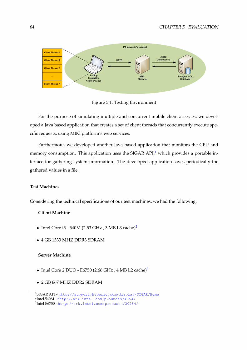
64 CHAPTER 5. EVALUATION
Figure 5.1: Testing Environment
For the purpose of simulating multiple and concurrent mobile client accesses, we devel-
oped a Java based application that creates a set of client threads that concurrently execute spe-
cific requests, using MBC platform’s web services.
Furthermore, we developed another Java based application that monitors the CPU and
memory consumption. This application uses the SIGAR API,1 which provides a portable in-
terface for gathering system information. The developed application saves periodically the
gathered values in a file.
Test Machines
Considering the technical specifications of our test machines, we had the following:
Client Machine
• Intel Core i5 - 540M (2.53 GHz , 3 MB L3 cache)2
• 4 GB 1333 MHZ DDR3 SDRAM
Server Machine
• Intel Core 2 DUO - E6750 (2.66 GHz , 4 MB L2 cache)3
• 2 GB 667 MHZ DDR2 SDRAM
1SIGAR API - http://support.hyperic.com/display/SIGAR/Home2Intel 540M - http://ark.intel.com/products/435443Intel E6750 - http://ark.intel.com/products/30784/

5.2. QUALITATIVE EVALUATION 65
5.2 Qualitative Evaluation
For qualitative evaluation, we considered the presentation and usability aspects, using for this
purpose the PUCNode once the widgets for the other nodes are similar. Furthermore, as stated
before in the architecture chapter (refer to chapter 3), we also considered the solution’s extensi-
bility and interoperability aspects.
Figure 5.2 shows the second stage of the PUCNode that is used by the users to fill and select
some parameters, which are used to create a new session in the PUC platform.
Figure 5.2: PUCNode Widget in the 2nd stage
Likewise, the Figure 5.3 shows the third stage of the PUCNode that is used by participants
to agree or not agree with the scheduling of the session.
In Figure 5.4 is depicted a screenshot of the modeling of a business process using the Oryx
editor. This process comprises several work items developed by us.
Here, we can conclude that our client application generally provides a good user experi-

66 CHAPTER 5. EVALUATION
Figure 5.3: PUCNode Widget in the 3rd stage
ence. It has a clear presentation, it is easy to use, and it is very functional. Furthermore, our
application is a lightweight solution which can be used in some terminals, such as TV, Smart-
phone, Laptop, and Tablet.
Regarding the extensibility and interoperability aspects, they are achieved as explained in
architecture chapter (refer to chapter 3).
5.3 Quantitative Evaluation
The quantitative evaluation is divided in three parts: MBC platform; Database; Client. How-
ever, our performance and scalability evaluation was mainly focused on the MBC platform. We
performed load tests to measure the memory and CPU consumption using the ApproverNode.
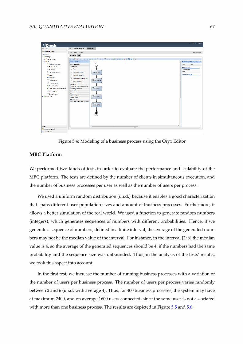
5.3. QUANTITATIVE EVALUATION 67
Figure 5.4: Modeling of a business process using the Oryx Editor
MBC Platform
We performed two kinds of tests in order to evaluate the performance and scalability of the
MBC platform. The tests are defined by the number of clients in simultaneous execution, and
the number of business processes per user as well as the number of users per process.
We used a uniform random distribution (u.r.d.) because it enables a good characterization
that spans different user population sizes and amount of business processes. Furthermore, it
allows a better simulation of the real world. We used a function to generate random numbers
(integers), which generates sequences of numbers with different probabilities. Hence, if we
generate a sequence of numbers, defined in a finite interval, the average of the generated num-
bers may not be the median value of the interval. For instance, in the interval [2; 6] the median
value is 4, so the average of the generated sequences should be 4, if the numbers had the same
probability and the sequence size was unbounded. Thus, in the analysis of the tests’ results,
we took this aspect into account.
In the first test, we increase the number of running business processes with a variation of
the number of users per business process. The number of users per process varies randomly
between 2 and 6 (u.r.d. with average 4). Thus, for 400 business processes, the system may have
at maximum 2400, and on average 1600 users connected, since the same user is not associated
with more than one business process. The results are depicted in Figure 5.5 and 5.6.

68 CHAPTER 5. EVALUATION
The average CPU utilization grows linearly with the number of running business pro-
cesses, and it never exceeds 65% (Figure 5.5). The growth is not completely linear because
we used a u.r.d., and the total of users has slight random variation in each sample, for reasons
stated before. However, these values are substantially the same.
Figure 5.5: CPU utilization growth with the number of running business processes
Likewise, the memory utilization also grows with the number of running business pro-
cesses (Figure 5.6). Once again, the growth is not completely linear due to the reasons stated
above.
Figure 5.6: Memory utilization growth with the number of running business processes

5.3. QUANTITATIVE EVALUATION 69
In the second test, we increase the number of active users with a variation of the number
of business processes per user. The number of business processes per user varies randomly
between 1 and 3 (u.r.d. with average 2). Thus, for 100 users, the system may have at maximum
300, and on average 200 running business processes since the same business process is only
associated with one user. The results are depicted in Figure 5.7 and 5.8.
The measured values of CPU utilization are lower than in the first test because the number
of users is much lower. In the second test we have a maximum of 100 users, while in first test
the system may have 2400 users (Figure 5.7).
Figure 5.7: CPU utilization growth with the number of active users
Regarding memory, the measured values are very similar because we use an external
database, and it allows removing the running instances of business processes from memory
and restoring them at some later time (Figure 5.8).
In both tests, we measured values that are acceptable according to the typical features of
an enterprise server. For instance, the server that we used (refer to section 5.1) for tests has
enough capacity for our application’s requirements.
In a scalable system we expect that the CPU and memory utilization grows linearly with
the number of running business processes and active users, so we may consider our solution
as a scalable system.

70 CHAPTER 5. EVALUATION
Figure 5.8: Memory utilization growth with the number of active users
Database
In order to analyse the usage of database local connections, we periodically gathered the num-
ber of open connections using a SQL command. We used the same two tests described above.
The results of these tests are depicted in Figure 5.9 and 5.10.
Figure 5.9: Open connections growth with the number of running business processes

5.3. QUANTITATIVE EVALUATION 71
Figure 5.10: Open connections growth with the number of active users
We verified that the system has some limitations regarding open connections because we
are using an open source database, which has a threshold of 100 connections. Although this
value can be raised, this is not recommended since the management of connections may not be
safe.4
When the system does not have more available connections in the pool (set of available
connections), it waits by one (by default 30 seconds). After this time, if the pool does not
have yet one available connection, the request is aborted and one exception is thrown. In the
third test (Figure 5.9) in spite of the threshold of open connections having been reached, the
waiting time typically was enough so that all requests finished successfully. However, in some
situations, this time was not enough and some requests were indeed aborted.
Client
In the client-side, we used the PUCNode to measure the application loading time and content
length as well as the time to serve the requests to the server and their respective content length.
These results are depicted in Table 5.1.
The measured values are different between the first times and following times because in
the following times there is static content, like images, which are not downloaded from server,
4http://www.postgresql.org/docs/8.2/static/runtime-config-connection.html
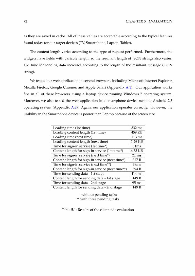
72 CHAPTER 5. EVALUATION
as they are saved in cache. All of these values are acceptable according to the typical features
found today for our target devices (TV, Smartphone, Laptop, Tablet).
The content length varies according to the type of request performed. Furthermore, the
widgets have fields with variable length, so the resultant length of JSON strings also varies.
The time for sending data increases according to the length of the resultant message (JSON
string).
We tested our web application in several browsers, including Microsoft Internet Explorer,
Mozilla Firefox, Google Chrome, and Apple Safari (Appendix A.1). Our application works
fine in all of these browsers, using a laptop device running Windows 7 operating system.
Moreover, we also tested the web application in a smartphone device running Android 2.3
operating system (Appendix A.2). Again, our application operates correctly. However, the
usability in the Smartphone device is poorer than Laptop because of the screen size.
Loading time (1st time) 532 msLoading content length (1st time) 459 KBLoading time (next time) 113 msLoading content length (next time) 1.26 KBTime for sign-in service (1st time*) 31msContent length for sign-in service (1st time*) 6.33 KBTime for sign-in service (next time*) 21 msContent length for sign-in service (next time*) 327 BTime for sign-in service (next time**) 39msContent length for sign-in service (next time**) 894 BTime for sending data - 1st stage 414 msContent length for sending data - 1st stage 149 BTime for sending data - 2nd stage 95 msContent length for sending data - 2nd stage 149 B
* without pending tasks** with three pending tasks
Table 5.1: Results of the client-side evaluation
5.4. SUMMARY 73
5.4 Summary
In this chapter, we performed an evaluation of our solution based in qualitative aspects (refer
to section 5.2) and quantitative (refer to section 5.3) metrics.
For qualitative aspects, we considered the application’s presentation and usability as well as
the solution’s extensibility and interoperability. Regarding the quantitative metrics, we consid-
ered the solution’s performance and scalability. The quantitative evaluation is divided in three
parts: MBC platform; Database; Client.
Concerning our server-side implementation (MBC platform), we measured the amount
of memory and CPU load used. Moreover, we also analyse the load in the database server,
including the number of open connections. The obtained results show that the MBC platform
is stable, and it is scalable according to the measured values of memory and CPU consumption.
The measured values are acceptable according to the typical features of an enterprise server.
The database software used has a threshold of 100 open connections. Thereby, we had to
setup the tests considering this threshold in order that no request was aborted.
In the client-side, we measured the application loading time and content length. Further-
more, we also measured the time to serve the requests to the server and their respective content
length. We can conclude that the client application provides a good user experience, and it is
a lightweight application, which can be used in several terminals, such as TV, Smartphone,
Laptop, and Tablet.
The solution complies with the extensibility and interoperability requirements, as stated be-
fore in the architecture chapter (refer to chapter 3).
In the final chapter, we will look into our evaluation results and present our final con-
clusions, which will validate the accomplishment of our objectives and will propose possible
future work.

74 CHAPTER 5. EVALUATION

6ConclusionsWe have now reached the end of this document. Thereby, we will present our final conclusions,
by first, presenting a review on all the phases of this work and this document’s chapters, in
Section 6.1. Then, we will look the functionalities provided by our solution, in Section 6.2. We
end our conclusion by presenting possible future work in our solution that we have identified
during the course of our work, in Section 6.3.
6.1 Review
Our objectives led us in an elaboration of an extensive survey in topics related with web appli-
cations, modeling and execution of business processes, and enterprise integration (interoper-
ability between enterprise applications). This allowed us to build a necessary knowledge base
for our solution’s design phase. It should be clear by now that the accomplishment of work’s
goals requires special attention to all of the aforementioned issues. The survey of these topics
was presented in the state of the art chapter (refer to chapter 2).
However, the survey performed was not enough to accomplish the work’s goals. Thereby,
we extended the study of technologies in the architecture chapter (refer to chapter 3). This latter
study had revealed quintessential for the conception of a system architecture that capitalised
in the usage of supporting technologies and transport mechanisms widely used on the web.
The implementation (refer to chapter 4) aimed to maximise extensibility and interoperabil-
ity of all developed code. Moreover, we aimed the integration of the proposed solution with
external entities, such as the PUC platform.
All of the undertaken work definitely paid off, as the evaluation phase, which we presented
in the evaluation chapter (refer to chapter 5), revealed very promising results, both quantita-
tively and qualitatively.

76 CHAPTER 6. CONCLUSIONS
6.2 Functionalities
The developed solution allows modeling business processes collaboratively, using the Oryx
editor. The business processes are stored in the central repository. Thereby, it is possible for a
partner to get a business process from another partner, and it is also possible to reuse business
processes in different scopes.
The activation and update of the business processes can be performed by users, using a
web application that is independent of the used terminal (TV, Smartphone, Laptop, Tablet), or
by external systems, using the web services technology.
The modeling of the business processes can be made using service nodes performing only
the necessary customization, or using default node types. We developed several work items,
which allow, for instance, an organization that wants to gather a rate of positive votes to ap-
prove a deal or management decision. We also developed a work item that allows to schedule
a new session in the PUC platform, and still, we developed a work item that allows to invoke
web services deployed elsewhere. All developed work items can save and share data with
other work items of the same process.
We use the Email Notifier to send notifications to the MBC’s users. The purpose of the noti-
fications is alert the users that they have a pending task in the MBC portal (web application).
In the end, we find that the system had a stable behaviour for the used load in the tests,
and it is a good solution to use with mobile devices since the measured values are compatible
with the capacity and communication costs of these types of devices.
6.3 Future Work
During the course of this work, we have identified a set of functional requirements and desired
properties that we would like to see implemented in future, such as:
Security Mechanisms: the current implementation does not yet support message ciphering
and user authentication mechanisms. Guaranteeing the confidentiality, integrity and au-
thentication of the exchanged messages is an essential requirement for collaborative ap-
plications that require minimal security;

6.3. FUTURE WORK 77
Database’s Software: the current implementation uses a database’s software that has a thresh-
old of 100 open connections. So, we propose the replace of the database’s software in
order of the solution allows a greater number of simultaneous transactions;
Additional Features: we would like to add additional features to our application prototype,
such as: management of the users role and policies over session; sending notifications
using a sms gateway; enriching and extension of the user interface; integration of the so-
lution with a e-commerce platform; integration of the MBC platform with jBPM Console.
We hope that the gained knowledge base, during the course of this work, is sufficient for
the future development of the above mentioned requirements and properties, and that our
solution, as it is today, becomes useful for future commercial developments in PT Inovacao’s
context.

78 CHAPTER 6. CONCLUSIONS
Bibliography
Bali, M. (2009). Drools JBoss Rules 5.0 Developer’s Guide. Packt Publishing.
Braude, E. J. & M. E. Bernstein (2011). Software Engineering: Modern Approaches (Second Edition). Wiley.
Brogi, A. & R. Popescu (2006). From BPEL processes to YAWL workflows. Web Services and Formal Methods, 107–122.
Brosey, W., R. Neal, & D. Marks (2002). Grand challenges of enterprise integration. In Emerging Technologies andFactory Automation, 2001. Proceedings. 2001 8th IEEE International Conference on, Volume 2, pp. 221–227. IEEE.
Bruneton, E., T. Coupaye, M. Leclercq, V. Quema, & J. Stefani (2006). The fractal component model and its supportin java. Software: Practice and Experience 36(11-12), 1257–1284.
Charfi, A. & M. Mezini (2007). Ao4bpel: An aspect-oriented extension to bpel. World Wide Web 10(3), 309–344.
Chen, Q. & M. Hsu (2001). Inter-enterprise collaborative business process management. In icccn, pp. 0253. Publishedby the IEEE Computer Society.
Chung, P., Y. Huang, S. Yajnik, D. Liang, J. Shih, C. Wang, & Y. Wang (1998). Dcom and corba side by side, step bystep, and layer by layer. C++ Report 10(1), 18–30.
Costello, R. (2007). Building web services the rest way. http://www.xfront.com/REST-Web-Services.html 11, 2007.
Courbis, C. & A. Finkelstein (2004). Towards an aspect weaving BPEL engine. In The Third AOSD Workshop onAspects, Components, and Patterns for Infrastructure Software (ACP4IS), Lancaster, UK. Citeseer.
Ellis, C., S. Gibbs, & G. Rein (1991). Groupware: some issues and experiences. Communications of the ACM 34(1),39–58.
Garrett, J. et al. (2005). Ajax: A new approach to web applications.
Georgakopoulos, D., M. Hornick, & A. Sheth (1995). An overview of workflow management: from process modelingto workflow automation infrastructure. Distributed and parallel Databases 3(2), 119–153.
Geric, S. (2010). The potential of service-oriented architectures. In Information Technology Interfaces (ITI), 2010 32ndInternational Conference on, pp. 471–476. IEEE.
Gerstbach, P. (2006). ebXML vs. Web Services Comparison of ebXML and the Combination ofSOAP/WSDL/UDDI/BPEL.
Giurca, A. & E. Pascalau (2008). Json rules. Proceedings of the Proceedings of 4th Knowledge Engineering and SoftwareEngineering, KESE 425, 7–18.
Hameseder, K., S. Fowler, & A. Peterson (2011). Performance analysis of ubiquitous web systems for smartphones.
Ibrahim, N. (2010). A survey on different interoperability frameworks of SOA systems towards seamless interoper-ability. In Information Technology (ITSim), 2010 International Symposium, Volume 3, pp. 1119–1123. IEEE.
Kaar, C. (2007). An introduction to widgets with particular emphasis on mobile widgets. Computing, Oct.
Kanchanavipu, K. (2008). An Integrated Model for SOA Governance. Report/IT University of Goteborg 2008: 002.
Koenig, J. (2004). Jboss jbpm. White Paper, JBoss Inc., Available from.
Kruessmann, T., A. Koschel, M. Murphy, A. Trenaman, & I. Astrova (2009). High availability: Evaluating opensource enterprise service buses. In Information Technology Interfaces, 2009. ITI’09. Proceedings of the ITI 2009 31st InternationalConference on, pp. 615–620. IEEE.
Lee, J., K. Siau, & S. Hong (2003). Enterprise Integration with ERP and EAI. Communications of the ACM 46(2), 54–60.
79

80 BIBLIOGRAPHY
Liu, C., Q. Li, & X. Zhao (2009). Challenges and opportunities in collaborative business process management:overview of recent advances and introduction to the special issue. Information Systems Frontiers 11(3), 201–209.
Lonjon, A. (2004). Business process modeling and standardization. BPTrends, in http://www. bptrends. com.
Mendling, J. & M. Hafner (2005). From inter-organizational workflows to process execution: generating BPEL fromWS-CDL. In On the Move to Meaningful Internet Systems 2005: OTM Workshops, pp. 506–515. Springer.
Menge, F. (2007). Enterprise service bus. In Free And Open Source Software Conference.
Murugesan, S. (2007). Understanding web 2.0. IT professional 9(4), 34–41.
Ning, F., Z. Xingshe, W. Kaibo, & Z. Tao (2008). Distributed Enterprise Service Bus based on JBI. In Grid and PervasiveComputing Workshops, 2008. GPC Workshops’ 08. The 3rd International Conference on, pp. 292–297. IEEE.
Nurseitov, N., M. Paulson, R. Reynolds, & C. Izurieta. Comparison of json and xml data interchange formats: A casestudy. Department of Computer Science Montana State University–Bozeman Bozeman, Montana 59715.
Oinn, T., M. Addis, J. Ferris, D. Marvin, M. Greenwood, T. Carver, M. Pocock, A. Wipat, & P. Li (2004). Taverna: atool for the composition and enactment of bioinformatics workflows. Bioinformatics.
Ouyang, C., M. Dumas, W. Aalst, A. Hofstede, & J. Mendling (2009). From business process models to process-oriented software systems. ACM transactions on software engineering and methodology (TOSEM) 19(1), 1–37.
Parr, A. & G. Shanks (2002). A taxonomy of ERP implementation approaches. In System Sciences, 2000. Proceedings ofthe 33rd Annual Hawaii International Conference on, pp. 10. IEEE.
Pasley, J. (2005). How BPEL and SOA are changing Web services development. Internet Computing, IEEE 9(3), 60–67.
Paulson, L. (2005). Building rich web applications with ajax. Computer 38(10), 14–17.
Peterson, J. (1977). Petri nets. ACM Computing Surveys (CSUR) 9(3), 223–252.
Qureshi, K. (2005). Enterprises application integration. In Emerging Technologies, 2005. Proceedings of the IEEE Sympo-sium on, pp. 340–345. IEEE.
Riehle, D. & H. Zullighoven (1996). Understanding and using patterns in software development. Theory and Practiceof Object Systems 2(1), 3–13.
Rummler, G. & A. Brache (1990). Improving performance. Jossey-Bass San Francisco.
Russell, N. & W. Van Der Aalst (2007). Evaluation of the BPEL4People and WS-HumanTask Extensions to WS-BPEL2.0 using the Workflow Resource Patterns. BPM Center Report BPM-07-10, BPMcenter. org.
Scheer, A. & M. Nuttgens (2000). ARIS architecture and reference models for business process management. BusinessProcess Management, 301–304.
Taylor, I., M. Shields, I. Wang, & R. Philp (2003). Grid enabling applications using triana. In Workshop on GridApplications and Programming Tools. Citeseer.
Umar, A. (2004). The emerging role of the web for enterprise applications and ASPs. Proceedings of the IEEE 92(9),1420–1438.
Van Der Aalst, W. & A. Ter Hofstede (2005). YAWL: yet another workflow language. Information Systems 30(4),245–275.
Van Der Aalst, W., A. Ter Hofstede, & M. Weske (2003). Business process management: A survey. Business ProcessManagement, 1019–1019.
Wilde, E. (2007). Putting things to rest.
Wu, J. & X. Tao (2010). Research of enterprise application integration based-on ESB. In Advanced Computer Control(ICACC), 2010 2nd International Conference on, Volume 5, pp. 90–93. IEEE.
Zalewski, A. (2007). A FMECA framework for Service Oriented Systems based on Web Services. In Dependability ofComputer Systems, 2007. DepCoS-RELCOMEX’07. 2nd International Conference on, pp. 286–293. IEEE.

AAppendicesA.1 Screenshots of the Web Browsers
Figure A.1: Login Widget in the Google Chrome Browser
Figure A.2: Login Widget in the Mozilla Firefox Browser

82 APPENDIX A. APPENDICES
Figure A.3: Login Widget in the Apple Safari Explorer Browser
Figure A.4: Login Widget in the Microsoft Internet Explorer Browser

A.2. SCREENSHOTS OF A SMARTPHONE DEVICE 83
A.2 Screenshots of a Smartphone Device
Figure A.5: Login Widget in a Smartphone Device
Figure A.6: User Widget in a Smartphone Device

84 APPENDIX A. APPENDICES
Figure A.7: PUCNode Widget in a Smartphone Device