
MB05 Service Manual - tim.id.autim.id.au/laptops/noname/fic mb05w.pdfFIC MB05W Service Manual FIC...
120
FIC MB05W Service Manual FIC MB05 Service Manual 1-1 MB05W (WB-B55) 1.1 Introduction This chapter provides the outline features and operation of the MB05 including the BIOS Setup program and other system options. The MB05 notebook offers the latest in advanced portable computing and multimedia technology that even outperforms most desktop computers. It incorporates the latest Intel Pentium - M processor and fully compatibles with an entire library of PC software based on operating systems such as Windows 2000 / XP. It also runs on future versions of Windows. It comes with a built-in keyboard, glide pad pointing device, sound system, PCMCIA slots, USB (Universal Serial Bus) port, IEEE 1394 port, advanced power management and more new multimedia features. 1.2 Feature Highlights The MB05 includes a variety of innovative features: Category Specification Stepping CPU Intel Pentium – M Processor : Banias 1.3/1.5 GHZ Core Logic Intel Montara-GM (North Bridge) : CPU(Banias) I/F VGA Controller LVDS I/F DVOB&DVOC IF. RGB analog I/F 200/266 DDR MEMORY I/F Hub-Link I/F Intel ICH4-M (South Bridge) : Integrated Hub-Link I/F to connect with PCI Bridge Dual IDE Master/Slave Controller ,Integrated DMA Controller 1.1/2.0 Universal Serial Bus Host Controller Integrated 10/100M Fast Ethernet MAC Controller Integrated Audio Controller with AC97 V2.2 Interface Advanced Power Management(ACPI) RTC Integrated PCI to LPC Bridge Integrated Audio Controller with AC97 Interface PCI Bus Interface (PCI 2.2 compliant) GPIO Advance PIC PDF created with FinePrint pdfFactory trial version http://www.fineprint.com
Transcript of MB05 Service Manual - tim.id.autim.id.au/laptops/noname/fic mb05w.pdfFIC MB05W Service Manual FIC...
FIC MB05W Service Manual
FIC MB05 Service Manual 1-1
MB05W MB05W
(WB-B55)
1.1 Introduction This chapter provides the outline features and operation of the MB05 including the BIOS Setup program and other system options. The MB05 notebook offers the latest in advanced portable computing and multimedia technology that even outperforms most desktop computers. It incorporates the latest Intel Pentium - M processor and fully compatibles with an entire library of PC software based on operating systems such as Windows 2000 / XP. It also runs on future versions of Windows. It comes with a built-in keyboard, glide pad pointing device, sound system, PCMCIA slots, USB (Universal Serial Bus) port, IEEE 1394 port, advanced power management and more new multimedia features.
1.2 Feature Highlights The MB05 includes a variety of innovative features:
Category Specification Stepping CPU Intel Pentium – M Processor
: Banias 1.3/1.5 GHZ
Core Logic
Intel Montara-GM (North Bridge) : CPU(Banias) I/F VGA Controller
LVDS I/F DVOB&DVOC IF. RGB analog I/F
200/266 DDR MEMORY I/F Hub-Link I/F
Intel ICH4-M (South Bridge) :
Integrated Hub-Link I/F to connect with PCI Bridge
Dual IDE Master/Slave Controller ,Integrated DMA Controller 1.1/2.0 Universal Serial Bus Host Controller Integrated 10/100M Fast Ethernet MAC Controller Integrated Audio Controller with AC97 V2.2 Interface Advanced Power Management(ACPI)
RTC Integrated PCI to LPC Bridge Integrated Audio Controller with AC97 Interface PCI Bus Interface (PCI 2.2 compliant) GPIO
Advance PIC
PDF created with FinePrint pdfFactory trial version http://www.fineprint.com

FIC MB05W Service Manual
1-2 FIC MB05 Service Manual
Cache Memory L1 Cache (Pentium Processor internal): 64KB 8-way cache associativity provides L2 Cache (Pentium Processor internal): 1024KB Advanced Transfer Cache,8 way associativity 8-way set associative, 32-byte line size, 1 line per sector
System Memory Expansion Memory: 2 SO-DIMM Slot (1.25”) Size: 128/256/512MB/1G Type: DDR DRAM, 3.3V Data Path: 64Bit Frequency : 266MHz Please refer to the MB05 Key component list in detail.
BIOS ROM Flash ROM 1st Vendor : SST 49LF040A PLCC Package 4Mbit LPC flash ROM
Super I/O SMSC LPC47N267 FDC, IEEE 1284 Printer Port Serial Port x 1 ports IR Port ASKIR, SIR, FIR, HPSIR, Consumer IR Plug and Play Support
RTC + NVRAM Integrated in South Bridge (Intel ICH4-M) Real Time Clock with 256 byte extended CMOS.
K/B Controller Mitsubishi M38859 LPC KBC Internal K/B, Touch Pad, External K/B or M/S Supported A20Gate,firmware version 2.14
PMU New PMU08 Mitsubishi M38859FFHP Embedded Controller
TBD
VGA Controller Embedded in Intel Montara-GM High Performance and high quality 3D accelerator Integrated dual DVO bridge Integrated LVDS Interface Integrated RGB analog Interface High performance 2D accelerator Complete TV-OUT/Digital Flat Panel Solution
VRAM Share system memory, UMA (using DVMT configuration) 8/16/32 MB
TV out encoder None CardBus Controller
RICOH R5C554 (PCI Card Bus controller) PC/Card Bus Type II x1 Build in smart card (none)
Sound
AC’97 CODEC Realtek ALC202 AC’97 Revision 2.2 Compliant
PDF created with FinePrint pdfFactory trial version http://www.fineprint.com
FIC MB05W Service Manual
FIC MB05 Service Manual 1-3
Modem MDC modem support V.90, K56flex, ITU-T V.34, V.32, RJ11 Jack TIA/EIA 602, V.42 ITU-T V.17, V.29, V.27ter, V.21 Ch2 TIA/EIA 578 Class1 FAX Wake up on Ring
On board LAN Realtek 8100BL Support LAN boot( no used) Support for auto-negotiation (10BASE-T and 100BASE-TX) Wake up On LAN( S1~S5)
3com Combo 802.11b 802.11 a+b
Support by Intel Calexico Mini-PCI Wireless LAN Card <Design Ready Only>
1394 RICOH R5C554 PCI-CARDBUS / 1394 OHCI-LINK / 1394 PHY
USB Intel ICH4-M
Integrated in South Bridge Intel ICH4-M) Three Independent UHCI USB 1.1 Host Controllers and One EHCI USB 2.0 Host Controller, support up to six port. Legacy Keyboard/Mouse support. Supports only one Debug port at port 1(first port), it is at USB 2.0 transfer rate..
IDE Interface (Intel ICH4-M)
Fast IDE: --Integrated multithreaded I/O link mastering with read pipelined streaming --Dual independent IDE channel each with 16 DW FIFO --Native and compatibility mode --PIO mode 0,1,2,3,4, and multiword DMA mode 0,1,2 --Ultra DMA 33/66/100
Printer Interface IEEE 1284-Compatible SPP mode (PS2 bi-directional mode)
EPP mode (EPP 1.7 and EPP 1.9 IEEE 1284 Compliant)
ECP mode (IEEE 1284 Compliant)
Serial Interface None External PS/2 Port (M38859)
External Keyboard or PS/2 Mouse Exclusively connected. Can use both device by using branch cable(option)
Universal Serial Bus (Intel ICH4-M)
--INTEL ICH4-M Integrated --Three Independent OHCI USB 1.1 Host Controllers and
One EHCI USB 2.0 Host Controller, support up to six port.
--Support up to 6 USB ports --Support legacy devices --Over current detection equipped --Optional configured each port as a wake-up source
Infrared None Modem 56K Data/Fax Modem (v.90) LAN 10/100 Base TX LAN
Lan boot support and WFM 2.0
LCD Panel 14.1” XGA 15 XGA ; Please refer to the MB05 Key component list in detail.
PDF created with FinePrint pdfFactory trial version http://www.fineprint.com

FIC MB05W Service Manual
1-4 FIC MB05 Service Manual
HDD 2.5 inch HDD (Standard) 9.5mm Height ; Please refer to the MB05 Key component list in detail.
CD-ROM (Option)
CD-ROM (9.5mm Height) ; Please refer to the MB05 Key component list in detail.
.
FDD(None)
USB FDD 3 mode Support ; Please refer to the MB05 Key component list in detail.
DVD (Option)
DVD 9.5mm Height ,8X ; Please refer to the MB05 Key component list in detail.
CD-RW,Combo 9.5mm Height ,24X ; Please refer to the MB05 Key component list in detail.
Pointing Device Internal Touch Pad PS/2 mouse I/F Pad ALPS : KGDDET 005A Please refer to the MB05T Key component list in detail.
Keyboard Internal Keyboard 6.5mm Height, 3.0mm Stroke, 19mm Pitch Please refer to the MB05 Key component list in detail.
Speakers (audio)
Two built-in dynamic speakers 40 x 20mm, 1W 4Ω
Microphone None Buzzer Not support Battery Battery Pack
Type: 8 cell Li-ION Battery with EEPROM Voltage: 14.4V Capacity: 4400mA(circle);3600mA(square) Vendor: SANYO Please refer to the MB05 Key component list in detail.
RTC Battery Ni-MH Battery Model: CR2032 Voltage: 2.9V Capacity: 225mAh Vendor: PANASONIC
DC/DC Converter
Daughter Board 5.0 V Max 6.0 A 3.3 V Max 6.0 A 12V Max 120mA
2.5V Max 3.5A 1.8V Max 3.5A
CPU Vcore 1.45V Max 22A AC Adapter ADP75FB : Delta(Consign)
PA-1600-05F : Liteon Input: AC100 – 240V, 50/60Hz Output: 19V, 60W Peak 80W(Liteon) 19V.75W(Delta) Size: 115mm x 50mm x 29mm (Delta) 110mm x 50mm x 29mm (Liteon) Vendor: Delta or Liteon Color : TBD ; Please refer to the MB05 Key component list in detail.
Size W=308mm, D=268mm, H=27.7~31mm.
PDF created with FinePrint pdfFactory trial version http://www.fineprint.com

FIC MB05W Service Manual
FIC MB05 Service Manual 1-5
Weight Approx 4.9 lb = 2.2Kg Battery Handling
Category Specification Remark Power On Li-ion 3.5 h
Battery Charging Max Change Current: 1.7A-1.75A±150mA
Power Off Li-ion 3.5 h
Battery Life 1st Li-ion 4 h TBD
Save to RAM 1st Li-ion 1 Days TBD
Charge 24 h CMOS Battery
Discharge 5 year
System on System off
Maximum 60W Consumption power Typical 30W TBD
PDF created with FinePrint pdfFactory trial version http://www.fineprint.com
FIC MB05W Service Manual
1-6 FIC MB05 Service Manual
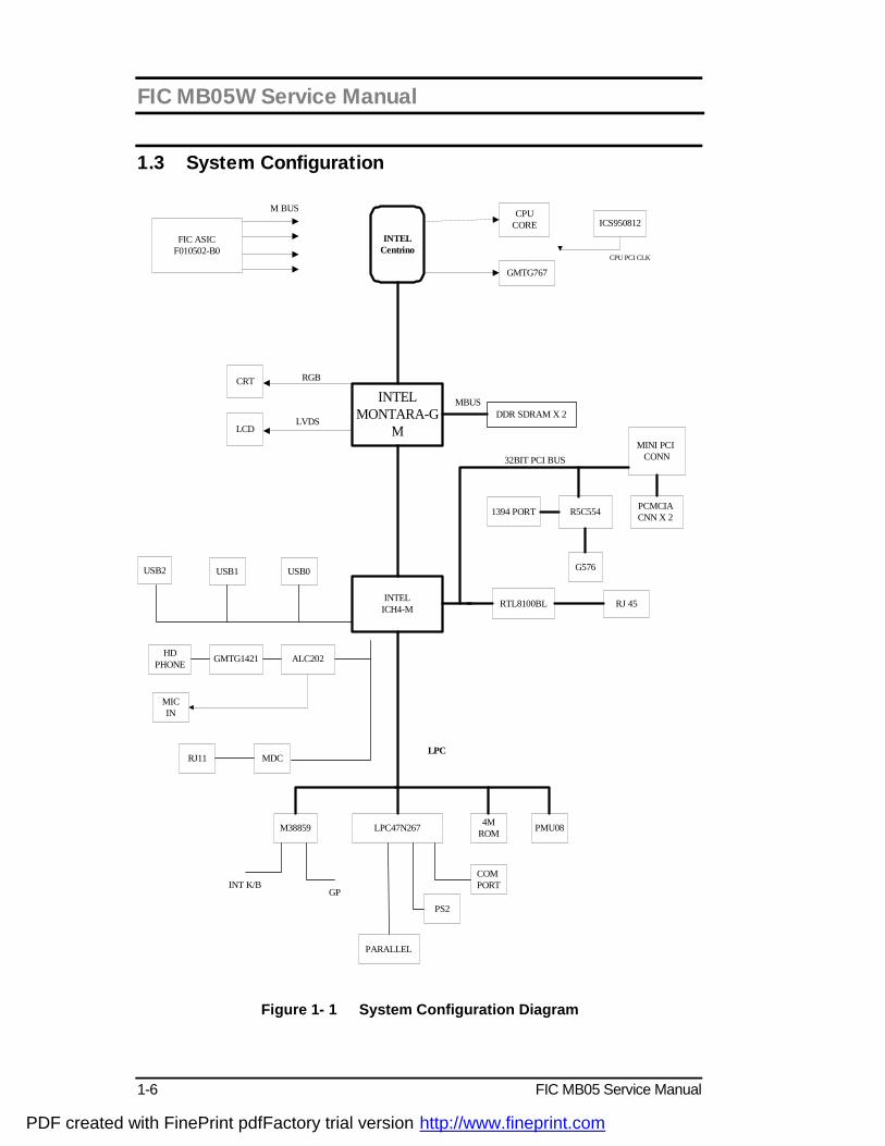
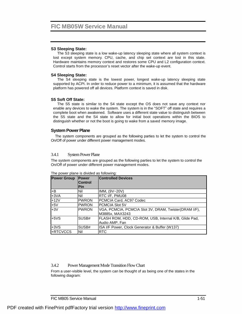
1.3 System Configuration
INTELCentrino
INTELICH4-M
LPC47N267
INTELMONTARA-G
M
CPUCORE
GMTG767
ICS950812
CPU PCI CLK
FIC ASICF010502-B0
CRT
LCD
USB1 USB0USB2
DDR SDRAM X 2
MINI PCI CONN
R5C554PCMCIA CNN X 2
G576
1394 PORT
RTL8100BL RJ 45
HDPHONE
ALC202GMTG1421
MDCRJ11
M38859 PMU08
COM PORT
4MROM
PARALLEL
PS2
INT K/BGP
RGB
LVDS
32BIT PCI BUS
LPC
MBUS
M BUS
MICIN
Figure 1- 1 System Configuration Diagram
PDF created with FinePrint pdfFactory trial version http://www.fineprint.com
FIC MB05W Service Manual
FIC MB05 Service Manual 1-7
1.4 Quick Tour of the Notebook Please take a moment to become familiar with the location and purpose of every control, the LED status panel, connectors and ports, which are illustrated in this section. It is recommended to first go through the User Guide of the notebook, which is shipped together with the notebook for information on how to operate its features.
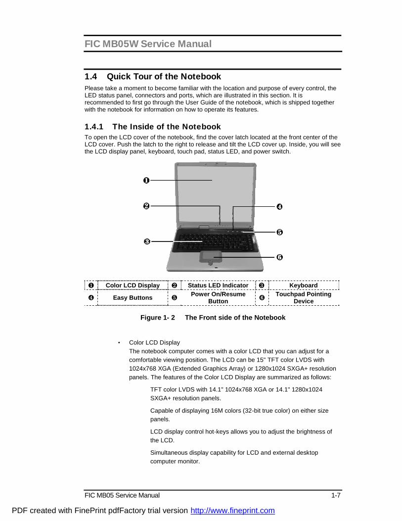
1.4.1 The Inside of the Notebook To open the LCD cover of the notebook, find the cover latch located at the front center of the LCD cover. Push the latch to the right to release and tilt the LCD cover up. Inside, you will see the LCD display panel, keyboard, touch pad, status LED, and power switch.
❶ Color LCD Display ❷ Status LED Indicator ❸ Keyboard
❹ Easy Buttons ❺ Power On/Resume Button ❻ Touchpad Pointing
Device
Figure 1- 2 The Front side of the Notebook
• Color LCD Display The notebook computer comes with a color LCD that you can adjust for a comfortable viewing position. The LCD can be 15" TFT color LVDS with 1024x768 XGA (Extended Graphics Array) or 1280x1024 SXGA+ resolution panels. The features of the Color LCD Display are summarized as follows:
ü TFT color LVDS with 14.1" 1024x768 XGA or 14.1" 1280x1024 SXGA+ resolution panels.
ü Capable of displaying 16M colors (32-bit true color) on either size panels.
ü LCD display control hot-keys allows you to adjust the brightness of the LCD.
ü Simultaneous display capability for LCD and external desktop computer monitor.
PDF created with FinePrint pdfFactory trial version http://www.fineprint.com

FIC MB05W Service Manual
1-8 FIC MB05 Service Manual
• Easy Buttons There are three easy buttons used for activating wireless function and accessing user-defined functions instantly and easily. Description of the easy buttons appears in the latter part of this section.
• Status LED Indicator Keeps you informed of your notebook computer’s current power status and operating status. Description of the status icons appears in the latter part of this section.
• Power On/Resume Button Switches the computer power on and off, or resumes whenever it is in Suspend mode.
• Keyboard
ü Standard QWERTY-key layout and full-sized 82/84 keys keyboard with Windows system hot-keys, embedded numeric keypad, 7 hot keys, inverted "T" cursor arrow keys, and separate page screen control keys.
ü Wide extra space below the keyboard panel for your wrist or palm to sit-on comfortably during typing.
• Touchpad Pointing Device Microsoft and IBM PS/2 mouse compatible with three select buttons as one Scroll button and two Touchpad click buttons. These three buttons array below the Glide pad. The middle one is located with the Scroll button that lets you execute the scroll page function. The two click buttons located at each side support tapping selection and dragging functions. These buttons work like a standard computer mouse. Simply move your fingertip over the Glide Pad to control the position of the cursor. Use the selection buttons below the Glide Pad to select menu items.
PDF created with FinePrint pdfFactory trial version http://www.fineprint.com

FIC MB05W Service Manual
FIC MB05 Service Manual 1-9
Easy Buttons
å Wireless LAN Button ç Easy Button 1 ➌ Easy Button 2
Figure 1- 3 Easy Button
• Wireless LAN Button Push this button to activate or inactivate the Wireless LAN. When you activate the wireless LAN function, it will search the wireless LAN signal automatically if you had installed the driver
• Easy Button 1 You can define the specific function by yourself to active the program. For example, you can define it to access the outlook 98/2000/2002... utility just by pressing this button. You can simplify several procedures in entering into Outlook 98/2000/2002... environment. For more understanding and interesting, you can refer Section 2.5 to recognize the driver installation procedures in activating Easy Button 1.
• Easy Button 2 You can define the specific function by yourself to active the program. For example, you can define it for providing a very convenient way in connecting Internet only by pressing this button. For more understanding and interesting, you can refer Section 2.5 to recognize the driver installation procedures in activating Easy Button 2.
PDF created with FinePrint pdfFactory trial version http://www.fineprint.com

FIC MB05W Service Manual
1-10 FIC MB05 Service Manual
Status LED Indicator Located just in front of the palmrest assembly, you will find three LEDs for the power and battery charge status. These LEDs are positioned to be visible even if the LCD cover is closed.
å Wireless LAN Status ç Power Indicator é Battery charging LED è HDD/CD Access ê Caps Lock ë Num Lock
Figure 1- 4 Status LED Indicator
• Power Indicator Lets you know that power to the system is turned on. This LED is positioned so that you can see the power state whether the LCD panel is opened or closed.
ü Lights green when the system is powered on
ü Lights green blinking when the system is in Suspend to RAM.
• Battery Charging LED Lights to indicate battery in charging status.
ü Lights green to indicate that the battery is in charging.
ü Lights off to indicate the battery is fully charged or no battery installed.
• HDD/CD Access When LED in green light indicates that the system is accessing either the Hard Disk or optical disk drive.
• Caps Lock When LED in green light indicates that the Caps Lock key on the keyboard is activated. When activated, all alphabet keys typed in will be in uppercase or capital letters.
• Num Lock When LED in yellow light indicates that the Num Lock key on the keyboard is activated. When activated, the embedded numeric keypad will be enabled.
PDF created with FinePrint pdfFactory trial version http://www.fineprint.com
FIC MB05W Service Manual
FIC MB05 Service Manual 1-11
• Wireless LAN Status When LED in green light indicates that the system is accessing data from or is retrieving data by wireless LAN.
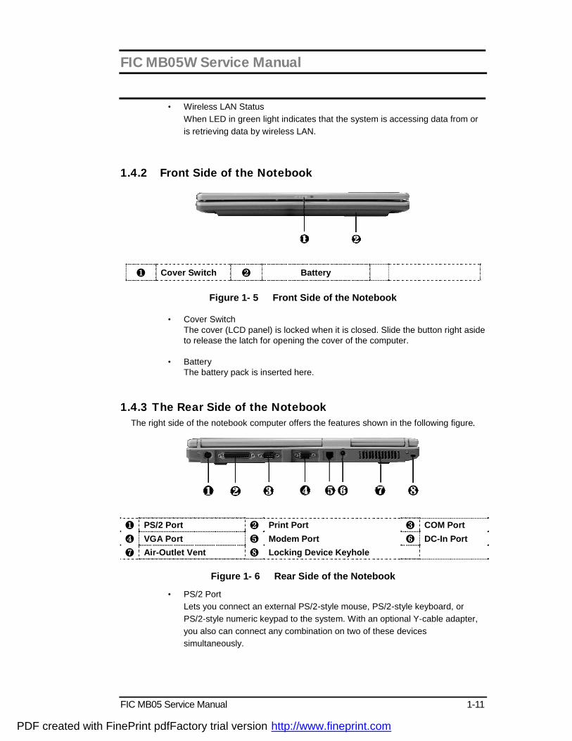
1.4.2 Front Side of the Notebook
❶ Cover Switch ❷ Battery
Figure 1- 5 Front Side of the Notebook
• Cover Switch The cover (LCD panel) is locked when it is closed. Slide the button right aside to release the latch for opening the cover of the computer.
• Battery The battery pack is inserted here.
1.4.3 The Rear Side of the Notebook The right side of the notebook computer offers the features shown in the following figure.
❶ PS/2 Port ❷ Print Port ❸ COM Port ❹ VGA Port ❺ Modem Port ❻ DC-In Port ❼ Air-Outlet Vent ❽ Locking Device Keyhole
Figure 1- 6 Rear Side of the Notebook
• PS/2 Port Lets you connect an external PS/2-style mouse, PS/2-style keyboard, or PS/2-style numeric keypad to the system. With an optional Y-cable adapter, you also can connect any combination on two of these devices simultaneously.
PDF created with FinePrint pdfFactory trial version http://www.fineprint.com

FIC MB05W Service Manual
1-12 FIC MB05 Service Manual
• Print Port Use this port to connect a parallel printer or other parallel device. The parallel port supports Enhanced Capabilities Port (ECP) standard. The standard provides you with a greater processing speed than the conventional parallel port. The port also supports bi-directional protocols.
+ The default setting for the parallel port on your notebook computer is set to Enhanced Capabilities Port (ECP). Some older parallel devices may not function with the ECP default setting. You may need to adjust the setting to accommodate your parallel device by changing the BIOS setting.
• COM Port Lets you connect a 9-pin external serial device such as a PDA, mouse, or other serial devices.
• VGA Port Lets you attach an external CRT monitor for wider display. You can run the LCD display and the external CRT monitor simultaneously or switch it to CRT only using the display hot-key.
• Modem Port A 56K internal fax/data modem is installed. It keeps you connected to the outside world through networks.
• DC-In Power Port Lets you connect the AC power adapter in supplying continuous power to your notebook and recharging the battery.
• Air-Outlet Vent Emits the heat out of your computer and keeps it within operating temperature.
• Locking Device Keyhole Lets you attach a Kensington security system or a compatible lock to secure your notebook computer.
1.4.4 The Left Side of the Notebook The left side of your notebook computer provides the features shown in the following figure. To see all the ports located on the left side, you can open the cover first.
PDF created with FinePrint pdfFactory trial version http://www.fineprint.com
FIC MB05W Service Manual
FIC MB05 Service Manual 1-13
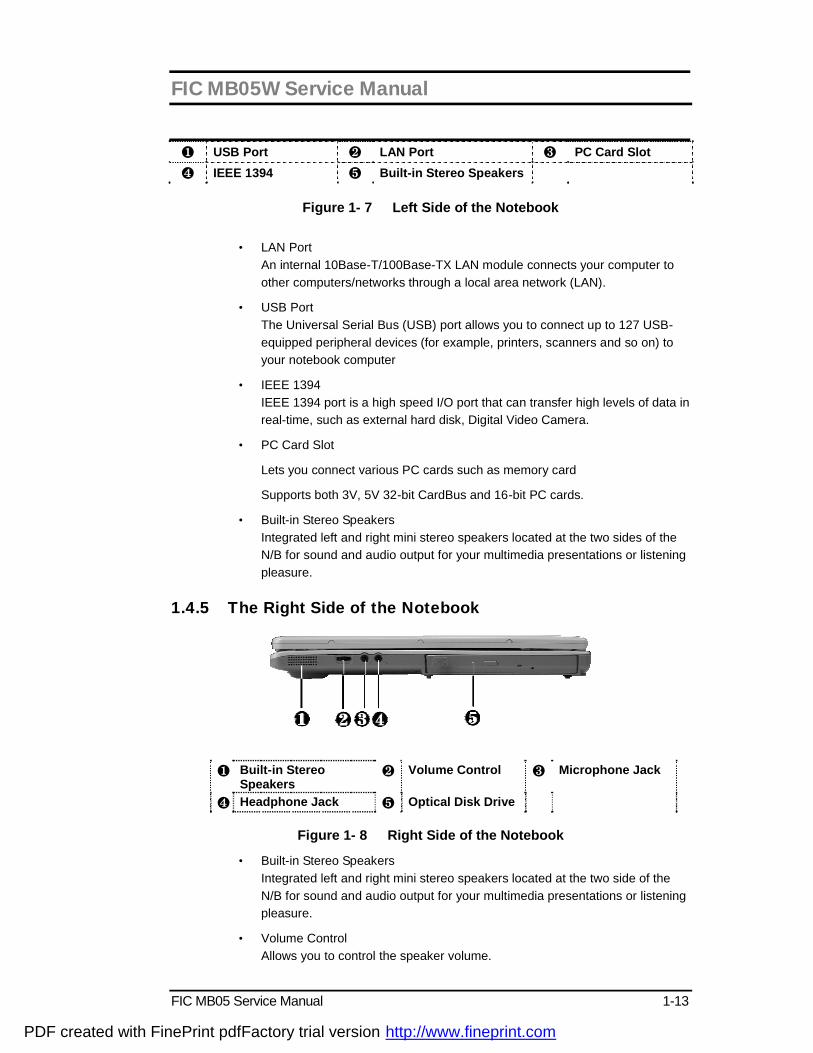
❶ USB Port ❷ LAN Port ❸ PC Card Slot ❹ IEEE 1394 ❺ Built-in Stereo Speakers
Figure 1- 7 Left Side of the Notebook
• LAN Port An internal 10Base-T/100Base-TX LAN module connects your computer to other computers/networks through a local area network (LAN).
• USB Port The Universal Serial Bus (USB) port allows you to connect up to 127 USB-equipped peripheral devices (for example, printers, scanners and so on) to your notebook computer
• IEEE 1394 IEEE 1394 port is a high speed I/O port that can transfer high levels of data in real-time, such as external hard disk, Digital Video Camera.
• PC Card Slot
ü Lets you connect various PC cards such as memory card
ü Supports both 3V, 5V 32-bit CardBus and 16-bit PC cards.
• Built-in Stereo Speakers Integrated left and right mini stereo speakers located at the two sides of the N/B for sound and audio output for your multimedia presentations or listening pleasure.
1.4.5 The Right Side of the Notebook
❶ Built-in Stereo
Speakers ❷ Volume Control ❸ Microphone Jack
❹ Headphone Jack ❺ Optical Disk Drive
Figure 1- 8 Right Side of the Notebook
• Built-in Stereo Speakers Integrated left and right mini stereo speakers located at the two side of the N/B for sound and audio output for your multimedia presentations or listening pleasure.
• Volume Control Allows you to control the speaker volume.
PDF created with FinePrint pdfFactory trial version http://www.fineprint.com

FIC MB05W Service Manual
1-14 FIC MB05 Service Manual
• Headphone Jack Lets you plug in a stereo headphone, powered speakers, or earphone set with 1/8 inch phono plug for personal listening.
• Microphone Jack Allows you to connect an external microphone for monophonic sound recording directly into your notebook computer.
• Optical Disk Drive Allows you to load and start programs from a compact disc (CD) or a digital video disc (DVD) and play conventional audio CDs. It also can make CD by using CD-R or CD-RW.
1.4.6 The Under Side of the Notebook
❶ Hard Disk Compartment
❷ Battery Bay ❸ Wireless LAN Compartment
❹ Memory Compartment
❺ Battery Release Latch
Figure 1- 9 Under Side of the Notebook
• Battery Release Latch Push the latch to the left end to remove the battery pack.
• Battery Bay Equipped with a choice of Lithium-Ion (Li-Ion) battery pack.
• Hard Disk Compartment Open this cover of this compartment to replace with other Hard Disk Drive. Please refer to Chapter 7 for how to replace it.
• Memory Compartment Remove the screw to find two DIMM slots. One is inserted with DDR SDRAM memory board configured by the factory. The other is empty for upgrade use.
• Wireless LAN Compartment Provides optional wireless LAN card inserted into this compartment for executing relative functions.
PDF created with FinePrint pdfFactory trial version http://www.fineprint.com
FIC MB05W Service Manual
FIC MB05 Service Manual 1-15
1.5 Notebook Accessories and System Options It is also important to understand the accessories that come along with the notebook and the options for fully utilizing the capabilities of the computer. This section describes briefly what these accessories and options are.
1.5.1 AC Adapter and Power Cord The AC Adapter supplies external power to your computer and at the same time charges the internal battery pack. The AC adapter has an auto-switching design that can connect to any 100VAC ~ 240VAC power outlets. Connect the adapter to the AC wall outlet using the power cord. You just change the power cord if you are going to use your notebook in other countries with different connector outlets. When you connect the AC adapter, it charges the battery whether or not the notebook computer is powered on. There is an LED on the AC adapter to indicate if DC power is already available. 1.5.2 Battery Pack Aside from the AC adapter, your computer can also be powered through the internal battery pack. The battery pack uses rechargeable Lithium-Ion (Li-Ion) battery cells that provide long computing hours when fully charged and power management enabled. You should always leave the battery inside your computer even when using the AC adapter as it also acts as a back-up power supply in case power from the AC adapter is cut off. It is also very important to have the battery pack always charged to prevent battery cell degradation.
1.5.3 Internal Modem Module The notebook allows you to insert a proprietary internal 56Kbps-modem card to the notebook found on the underside of the notebook. The internal modem card supports only fax and data communication and is V.90-compliant. You connect the telephone line to the RJ-11 jack found on the rear side of the notebook. 1.5.4 Internal Ethernet LAN Module This notebook comes with an optional 10Base-T/100Base-TX LAN module that supports data transfer rates at 10Mbps and can be up to 100Mbps.
1.5.5 DVD-ROM Drive Other than the internal CD-ROM drive, the notebook also provides optional factory built-in DVD-ROM drive. DVD-ROM drives are also backward compatible with CD-ROM, so you can also use any audio CDs, video CDs, photo CDs, and CD-R. Using a software MPEG-2/DVD program, the notebook can playback any commercial DVD movie titles.
1.6 System BIOS SETUP Program Your computer is likely to have been properly setup and configured by your dealer prior to delivery. However, you may find it necessary to use the computer’s BIOS (Basic Input-Output System) Setup program to change system configuration information, such as the current date and time, or your hard disk drive type. The Setup program can be accessed when you power on the system and pressing the <F2> function key. The settings that you specify within the Setup program are recorded in a special area memory called the CMOS RAM. This memory is backed up by a battery so that is will not be erased when you turn off or reset the system. Whenever you turn on the computer, the system will read the settings stored in the CMOS RAM and compare them to the equipment check conducted during the Power On Self Test (POST). If an error occurs, an error message will be
PDF created with FinePrint pdfFactory trial version http://www.fineprint.com
FIC MB05W Service Manual
1-16 FIC MB05 Service Manual
displayed on the screen, and you will then be prompted to run the Setup Program. As the POST (Power-On Self Test) executes during the boot up process, the screen will display the following message:
Press <F2> to Enter SETUP Press the <F2> key to run the BIOS Setup program. The BIOS Setup program is organized into five menus which you can select using the ß and à keys. To move from one option to another, you use the up and down arrow keys while using the <F5> and <F6>, or <+>and <-> keys to change the settings. On the right hand side of the screen are some brief help descriptions of each item you want to change. On the BIOS Setup program, you will find the following parts on the screen:
• Item Specific Help The right side of the screen. This area describes each parameter and its available settings.
• Menu Bar The top line of the screen. Each of the five selections displays its own screen.
• Parameters The left side of the screen. This area lists the parameters and their current settings.
• Key Status Bar The bottom part of the screen. These lines display the keys available to move the cursor, select a particular function and so forth.
To exit the BIOS Setup program, simply press the <Esc> key and select from the Exit menu whether you want to Save changes and exit; Discard Changes and exit.
PDF created with FinePrint pdfFactory trial version http://www.fineprint.com

FIC MB05W Service Manual
FIC MB05 Service Manual 1-17
1.6.1 Using the Main Menu Setup
Phoenix BIOS Setup Ut il ity Main Advanced Security Boot Exit
Item Specific Help
System Time: [12 :00 :00] <Tab>, <Shift-Tab>, System Date: [02/19/2003] or <Enter> selects
LAN MAC Address 00-40-CA-C3-9A-07 field.
Boot Display Device: [Both]
4 Primary Master [30006MB]
Secondary Master Installed CD/DVD
System Memory: 640 KB
Extended Memory: 112640 KB
CPU Type: Intel Pentium-M Processor
CPU Speed: 1300 MHz
BIOS Version: A.1A-2973-0812
F1 Help á â Select Item -/+ Change Values F9 Setup Defaults
Esc Exit ß--> Select Menu Enter Select 4Sub-Menu F10 Save and Exit
• System Time Allows you to change the system time using the hour:minute:second format of the computer. Enter the current time for reach field and use the <Tab>, <Shift>+<Tab>, or <Enter> key to move from one field or back to another. You can also change the system time from your operating system.
• System Date Allows you to set the system date using the month/date/year format. Enter the current time for reach field and use the <Tab>, <Shift>+<Tab>, or <Enter> key to move from one field or back to another. You can also change the system time from your operating system.
• LAN MAC Address This field reports the MAC address of the LAN module on your notebook.
• Boot Display Device Lets you select the display device.
• Primary Master This field display various parameters for the hard disk drive. If type [Auto] is selected, the system automatically sets these parameters. If type [User] is selected, Cylinders, Heads and Sectors and other value can be edited.
PDF created with FinePrint pdfFactory trial version http://www.fineprint.com

FIC MB05W Service Manual
1-18 FIC MB05 Service Manual
• Secondary Master This field is for information only as the BIOS automatically detects the optical drive.
• System Memory This field reports the amount of base (or conventional) memory found by the BIOS during Power-On Self-Test (POST).
• Extended Memory This field reports the amount of extended memory found by the BIOS during Power-On Self-Test (POST).
• CPU Type This field reports the CPU type information detected by the BIOS during Power-On Self-Test (POST).
• CPU Speed This field reports the CPU speed information detected by the BIOS during Power-On Self-Test (POST).
• BIOS Version This field is for information only as the BIOS displays the BIOS version during the Power-On Self-Test (POST).
1.6.2 Internal HDD Sub-Menu
Phoenix BIOS Setup Ut il ity
Main Advanced Security Boot Exit
Primary Master: [30006MB] Item Specific Help
Type: [Auto] Select the drive type LBA Format corresponding to the
Total Sectors: [58605120] fixed disk installed
Maximum Capacity: 30006MB in your system.
If type USER is
Multi-Sector Transfers: [16 Sectors] selected, Cylinders,
LBA Mode Control: [Enabled] Heads & Sectors are
32 Bit I/O: [Disabled] Edited directly.
Transfer Mode: [FPIO 4/DMA 2]
Ultra DMA Mode: [Mode 5]
F1 Help á â Select Item -/+ Change Values F9 Setup Defaults
Esc Exit ß--> Select Menu Enter Select 4Sub-Menu F10 Save and Exit Use the Type field to select the drive type installed. You can select different drive types as CD-ROM, User, Auto, or None by pressing <Space> bar. Set this option to Auto so your computer will automatically detect the drive type during power on. Set this option to None when your computer is not installed any devices. Press <Esc> to return to the Main Menu.
PDF created with FinePrint pdfFactory trial version http://www.fineprint.com

FIC MB05W Service Manual
FIC MB05 Service Manual 1-19
1.6.3 Using the Advanced CMOS Setup
Phoenix BIOS Setup Ut il ity Main Advanced Security Boot Exit
Item Specific Help
NumLock [LockOn] Selects Power-on state
for NumLock
Embedded Share Memory [16MB]
Quiet Boot [Enabled]
Screen Expansion [Disabled]
Legacy USB Support [Enabled]
USB 2.0 [Enabled]
PXE OPROM [Disabled]
Wake on LAN from S5: [Enabled]
4 I/O Device Configuration
F1 Help á â Select Item -/+ Change Values F9 Setup Defaults
Esc Exit ß--> Select Menu Enter Select 4Sub-Menu F10 Save and Exit
• Num-Lock Lets you specify Enabled or Disabled for activating or inactivating Num-Lock function when system is booting.
• Embedded Share Memory Lets you specify the sharing memory size of the Video chip from DDR SDRAM. The Default sharing size is 32MB. You should carefully specify the value, since while the set value is too high, the memory size of your software application will be reduced.
• Quiet Boot Lets you specify the boot screen to Logo screen or POST screen by choosing Disabled or Enabled, respectively.
• Screen Expansion Lets you choose full-size screen or reduced size screen for viewing the display mode.
• Legacy USB Support Lets you specify Enabled or Disabled for activating or inactivating Legacy USB Device function when system is booting.
• USB 2.0 Lets you specify Enabled or Disabled for activating or inactivating USB 2.0 Device function when system is booting.
PDF created with FinePrint pdfFactory trial version http://www.fineprint.com
FIC MB05W Service Manual
1-20 FIC MB05 Service Manual
• PXE OPROM Lets you specify Enabled or Disabled for activating or inactivating PXE OPROM Device function when system is booting. Please set it to default value
• Wake on LAN from S5 Lets you activate or inactivate the LAN function when system is booting by specifying Enabled or Disabled option. Wake on LAN is a function that you can boot the system from LAN remotely.
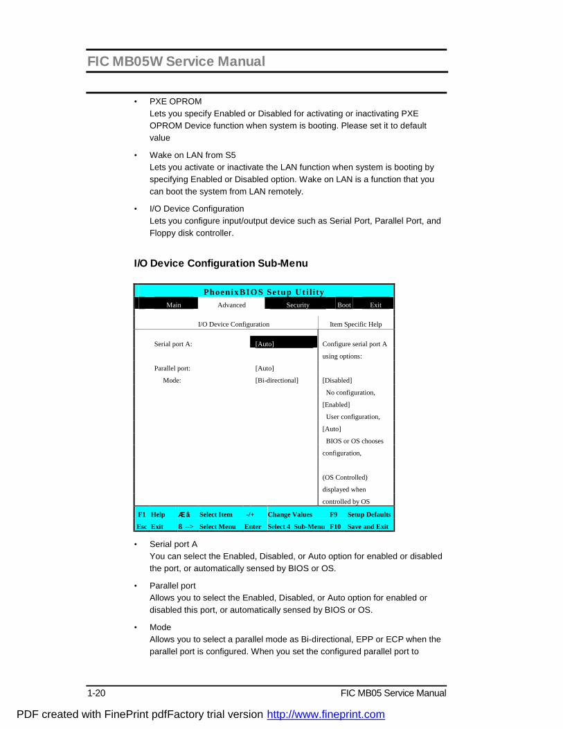
• I/O Device Configuration Lets you configure input/output device such as Serial Port, Parallel Port, and Floppy disk controller.
I/O Device Configuration Sub-Menu
PhoenixBIOS Setup Ut i l ity
Main Advanced Security Boot Exit
I/O Device Configuration Item Specific Help
Serial port A: [Auto] Configure serial port A
using options:
Parallel port: [Auto]
Mode: [Bi-directional] [Disabled]
No configuration,
[Enabled]
User configuration,
[Auto]
BIOS or OS chooses
configuration,
(OS Controlled)
displayed when
controlled by OS
F1 Help á â Select Item -/+ Change Values F9 Setup Defaults
Esc Exit ß--> Select Menu Enter Select 4Sub-Menu F10 Save and Exit
• Serial port A You can select the Enabled, Disabled, or Auto option for enabled or disabled the port, or automatically sensed by BIOS or OS.
• Parallel port Allows you to select the Enabled, Disabled, or Auto option for enabled or disabled this port, or automatically sensed by BIOS or OS.
• Mode Allows you to select a parallel mode as Bi-directional, EPP or ECP when the parallel port is configured. When you set the configured parallel port to
PDF created with FinePrint pdfFactory trial version http://www.fineprint.com
FIC MB05W Service Manual
FIC MB05 Service Manual 1-21
Enabled, you need to set the parameter of Base I/O address and IRQ for this port.
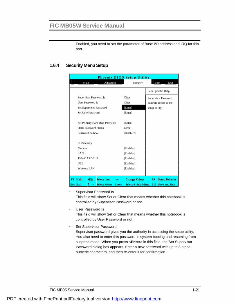
1.6.4 Security Menu Setup
Phoenix BIOS Setup Ut il ity Main Advanced Security Boot Exit
Item Specific Help
Supervisor Password Is Clear Supervisor Password
User Password Is Clear controls access to the
Set Supervisor Password [Enter] setup utility.
Set User Password [Enter]
Set Primary Hard Disk Password [Enter]
HDD Password Status Clear
Password on boot [Disabled]
I/O Security
Modem: [Enabled]
LAN: [Enabled]
1394/CARDBUS: [Enabled]
USB: [Enabled]
Wireless LAN: [Enabled]
F1 Help á â Select Item -/+ Change Values F9 Setup Defaults
Esc Exit ß--> Select Menu Enter Select 4Sub-Menu F10 Save and Exit
• Supervisor Password Is This field will show Set or Clear that means whether this notebook is controlled by Supervisor Password or not.
• User Password Is This field will show Set or Clear that means whether this notebook is controlled by User Password or not.
• Set Supervisor Password Supervisor password gives you the authority in accessing the setup utility. You also need to enter this password in system booting and resuming from suspend mode. When you press <Enter> in this field, the Set Supervisor Password dialog box appears. Enter a new password with up to 8 alpha-numeric characters, and then re-enter it for confirmation.
PDF created with FinePrint pdfFactory trial version http://www.fineprint.com

FIC MB05W Service Manual
1-22 FIC MB05 Service Manual
• Set User Password This field is only available when Supervisor Password has set. Enter the user password when boot the system or resume from suspend mode. But if the Write Protect is set in the Fixed disk boot sector field, you should enter a supervisor password to access the fixed disk when boot the system or resume from suspend mode.
• Set Primary Hard Disk Password This password gives you the authority in accessing the Hard Disk. When you press <Enter> in this field, the Set Supervisor Password dialog box appears. Enter a new password with up to 8 alpha-numeric characters, and then re-enter it for confirmation.
• HDD Password Status This field will show Set or Clear that means whether this notebook is controlled by HDD Password or not.
• Password on Boot If you set this field to Enabled, your computer will ask for the password each time you boot your computer.
• Modem Lets you specify Enabled or Disabled for activating or inactivating Modem Device function when system is booting.
• LAN Lets you specify Enabled or Disabled for activating or inactivating LAN Device function when system is booting.
• 1394/CARDBUS Lets you specify Enabled or Disabled for activating or inactivating 1394/CARDBUS Device function when system is booting.
• USB Lets you specify Enabled or Disabled for activating or inactivating USB Device function when system is booting.
• Wireless LAN Lets you specify Enabled or Disabled for activating or inactivating Wireless LAN Device function when system is booting.
PDF created with FinePrint pdfFactory trial version http://www.fineprint.com

FIC MB05W Service Manual
FIC MB05 Service Manual 1-23
1.6.5 Using the Boot Setup This item allows you to set the search drive sequence where the system will try to boot up first.
Phoenix BIOS Setup Ut il ity
Main Advanced Security Boot Exit
Item Specific Help
F12 Multi Boot Menu: [Enabled] Keys used to view or
configure devices:
PXE Boot with WOL: [Disabled] <Enter> expands or
collapses devices with
Boot Sequence: a + or -
+Hard Drive <Ctrl+Enter> expands
Removable Devices all
CD-ROM Drive <Shift + 1> enables or
disables a device.
<+> and <-> moves the
device up or down.
F1 Help á â Select Item -/+ Change Values F9 Setup Defaults
Esc Exit ß--> Select Menu Enter Select 4Sub-Menu F10 Save and Exit
• F12 Multi Boot Menu Lets you specify Enabled or Disabled for activating or inactivating the Multi Boot function by pressing F12 function key when system is booting.
• PXE Boot with WOL This field is for information only as whether the BIOS can automatically detect the PXE Boot with WOL status or not.
• Boot Sequence To select the boot device, you can use the up or down arrow key, then press <+> to move up the device in the list or press <-> to move down the device in the list.
PDF created with FinePrint pdfFactory trial version http://www.fineprint.com
FIC MB05W Service Manual
1-24 FIC MB05 Service Manual
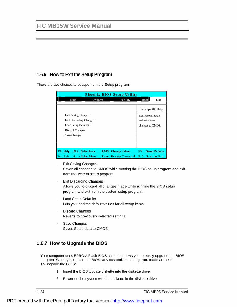
1.6.6 How to Exit the Setup Program There are two choices to escape from the Setup program.
Phoenix BIOS Setup Ut il ity
Main Advanced Security Boot Exit
Item Specific Help
Exit Saving Changes Exit System Setup
Exit Discarding Changes and save your
Load Setup Defaults changes to CMOS.
Discard Changes
Save Changes
F1 Help á â Select Item F5/F6 Change Values F9 Setup Defaults
Esc Exit ß--> Select Menu Enter Execute Command F10 Save and Exit
• Exit Saving Changes Saves all changes to CMOS while running the BIOS setup program and exit from the system setup program.
• Exit Discarding Changes Allows you to discard all changes made while running the BIOS setup program and exit from the system setup program.
• Load Setup Defaults Lets you load the default values for all setup items.
• Discard Changes Reverts to previously selected settings.
• Save Changes Saves Setup data to CMOS.
1.6.7 How to Upgrade the BIOS
Your computer uses EPROM Flash BIOS chip that allows you to easily upgrade the BIOS program. When you update the BIOS, any customized settings you made are lost. To upgrade the BIOS:
1. Insert the BIOS Update diskette into the diskette drive.
2. Power on the system with the diskette in the diskette drive.
PDF created with FinePrint pdfFactory trial version http://www.fineprint.com

FIC MB05W Service Manual
FIC MB05 Service Manual 1-25
3. On the DOS prompt, type the following command. A:\>Phlash XXXXXX.ROM (BIOS filename) or A:\>XXXXXX.BAT (Batch file for BIOS file)
4. Press <Enter> to run this BIOS utility. After the system has been successfully run this program, a message similar to the following appears: Flash memory has been successfully programmed, press any key to restart the system. If the system does not restart, turn it off, then turn on again.
5. Press any key to restart this system. Contact your dealer for the latest BIOS update file.
PDF created with FinePrint pdfFactory trial version http://www.fineprint.com

FIC MB05W Service Manual
1-26 FIC MB05 Service Manual
2.1 Overview This chapter provides guidelines on installing the device drivers for the built-in features of the MB05. Most of the driver installation procedures mentioned here are only for Windows XP. This chapter also includes procedures on how to upgrade major internal system components like CPU, memory, hard disk, and feature card modules. 2.2 Notebook Drivers and Utilities The notebook requires several device drivers that you need to install and setup before you can fully operate the notebook. These are:
• Intel 855GM VGA Driver – Windows XP • ALC201A Audio Driver – Windows XP • ALPS Touch Pad Driver – Windows XP • Montara-GM Chipset Driver – Windows XP • Easy Button PRO utility – Windows XP • Askey MDC Modem – Windows XP • Realtek 8100BL LAN driver– Windows XP • Intel Wireless LAN driver – Windows XP
i Visit FIC Support website ftp://ftp.pcg.fic.com.tw/NBTECH/MB05 for the latest driver updates.
2.2.1 Installing Windows XP from CD / DVD ROM This section provides Windows XP installation guide from the CD-ROM or DVD-ROM device. Installing Windows XP from CD-ROM / DVD-ROM To install Windows XP directly from your CD-ROM, insert the Windows XP installation CD into CD-ROM drive with following the instructions on the screen to finish the installation. You could go to Boot menu of BIOS setup menu to confirm the priority of boot device. Use arrow key to select "ATAPI CD-ROM Drive", and then use "+" or "-" to move it to the top. Go to Exit menu and select “Exit Saving Changes”.
2.2.2 Installing the VGA Device Driver Your notebook computer uses the high-performance Intel 855GM VGA controller, which is an AGP 4x video local bus, 2D/3D Graphic Engine. Following is the procedure for installing the VGA Driver for Windows XP : Installing VGA Driver for Windows XP 1. Click the Start button, then point to Settings, and click Control Panel. 2. Double-click on the System icon, Hardware, and then click on the Device Manager
folder tab. 3. Under the Other Devices line, you will find the Video Controller (VGA compatible),
click Uninstall, OK, and then Scan for Hardware Changes buttons to appear the New
PDF created with FinePrint pdfFactory trial version http://www.fineprint.com

FIC MB05W Service Manual
FIC MB05 Service Manual 1-27
Hardware Found Message Box. 4. In the Found New Hardware Wizard message box which shows searching Video
Controller (VGA compatible) driver. Click Next to proceed the further step. 5. Select "Search for a suitable driver for my device", and click Next. 6. Tick on "Specify a location box", then, click Next and Browse buttons, and then
navigate to the VGA driver location as "\Drivers\ WinXP\VGA". 7. Click OK and Next to begin searching the driver. Click Next to continue installing the
driver. 8. Click Finish button to finish installing VGA driver and Click Yes to restart the computer. 2.2.3 Installing the Audio Device Driver Your notebook computer uses Realtek Audio controller. Installing Audio Driver for Windows XP 1. Click the Start button, then point to Settings, and click Control Panel. 2. Double-click on the System icon, Hardware and then click on the Device Manager folder
tab. 3. Under the Other Devices line, you will find the Multimedia Audio Controller, click
Uninstall, OK, and then Scan for hardware changes buttons to appear the New Hardware Found Message Box.
4. In the Found New Hardware Wizard message box which shows searching Multimedia
Audio Controller driver. Click Next to proceed to the next step. 5. Select "Search for a suitable driver for my device", and click Next. 6. Tick on "Specify a location box", then click Next and Browse buttons, and navigate to
the Audio driver location as "\Drivers\ WinXP\Audio". 7. Click OK and Next to begin searching the driver. The Add New Hardware will found Intel
ALC201A Audio. 8. Click Yes to continue installing the driver. Click Finish button to finish installing Audio
driver. 2.2.4 Installing Touch Pad Driver Following is the procedure for installing Synaptics touch pad driver. Installing ALPS Touch Pad Driver for Windows XP 1. Boot Windows from your hard disk and insert the diskette containing touch pad driver.
PDF created with FinePrint pdfFactory trial version http://www.fineprint.com

FIC MB05W Service Manual
1-28 FIC MB05 Service Manual
2. Click the Start button, then click Run. In the Run dialog box, click Browse button and navigate to the directory as "\Driver\WinXP\Touch Pad\setup.exe", path according to your Operating System and run "Setup.exe".
3. Execute the setup program and then select the language for this installation. After that, a
Welcome dialog box appears. 4. Click Next continuously three times when the screen appears the Next button. 5. Click OK to restart your system. 2.2.5 Installing Internal Modem Device Driver Your notebook computer may come with an optional internal modem. The internal modem is a 56Kps V.90 Askey MDC modem. Installing Internal Modem for Windows XP
1. Boot Windows from your hard disk and insert the disc containing the Modem driver for
Windows. 2. Click the Start button and then click Run. In the Run dialog box, click Browse button
and navigate to the directory as "\driver\WinXP\MODEM\setup.exe" where the modem driver is located.
3. Click OK to process the installation of modem driver. Follow the instruction to finish the
installation. 4. With “Yes, I want to restart my computer now” selected, click Finish to complete the
modem installation. 2.2.6 Installing Internal LAN Device Driver Your notebook computer may come with an optional internal LAN, which uses the Intel 562EZ chip. Please follow the procedures below for installing the LAN driver: Installing Internal LAN for Windows XP 1. Click the Start button, then point to Settings, and click Control Panel. 2. Double-click on the System icon, Hardware and then click on the Device Manager folder
tab. 3. Under the Other Devices line, you will find the Ethernet Controller, click Uninstall, OK,
then Scan for hardware changes buttons to appear the New Hardware Found Message Box.
4. In the Found New Hardware Wizard message box which shows searching Ethernet
Controller driver. Click Next to proceed to the next step. 5. Select "Search for a suitable driver for my device", and click Next. 6. Tick on "Specify a location box". Then, click Next and Browse buttons and navigate to
the LAN driver location as "\Drivers\WinXP\LAN". Click OK and Next to begin searching
PDF created with FinePrint pdfFactory trial version http://www.fineprint.com

FIC MB05W Service Manual
FIC MB05 Service Manual 1-29
the driver. 7. The Add New Hardware will found Intel Fast Ethernet . Click Yes to continue installing
the driver. 8. Click Finish button to finish installing LAN driver. 2.2.7 Installing EzButton Driver Following is the procedure for installing Easy Button driver. Installing Easy Button driver for Windows XP
1. Boot Windows from your hard disk and insert the disc containing the Easy Button driver.
2. Click the Start button, then click Run. In the Run dialog box, click Browse button and navigate to the directory as "\Drivers\WinXP\Easy Button\Ez Button.exe".
3. Run the execution file for installing the Easy Button driver, and then click Finish after complete the installing procedure.
2.2.8 Installing the Chipset Driver Your notebook computer uses the advanced chipset. Installing the driver to enhance the stability and performance.
Installing Chipset device driver for Windows XP 1. Click the Start button, then point to Run. The Run dialog box appears. 2. Click the Browse button and specify the directory as.
"E:\Drivers\WinXP\Chipset\Setup.exe". 3. Click "OK" to execute the setup program. The Setup box appears. 4. Click Next continuously to install this driver when screen displays this command. 5. Tick the option "Yes, I want to restart my computer now.", and press Finish to
restart your system. 2.3 System Upgrades This section provides an easy step in doing system upgrades for your notebook computer.
PDF created with FinePrint pdfFactory trial version http://www.fineprint.com
FIC MB05W Service Manual
1-30 FIC MB05 Service Manual
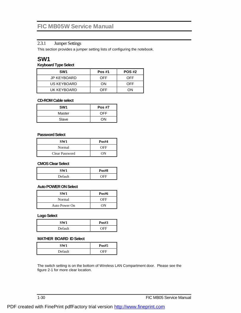
2.3.1 Jumper Settings This section provides a jumper setting lists of configuring the notebook.
SW1 Keyboard Type Select
SW1 Pos #1 POS #2 JP KEYBOARD OFF OFF US KEYBOARD ON OFF UK KEYBOARD OFF ON
CD-ROM Cable select
SW1 Pos #7 Master OFF Slave ON
Password Select
SW1 Pos#4 Normal OFF
Clear Password ON CMOS Clear Select
SW1 Pos#8 Default OFF
Auto POWER ON Select
SW1 Pos#6 Normal OFF
Auto Power On ON Logo Select
SW1 Pos#3 Default OFF
MATHER BOARD ID Select
SW1 Pos#5 Default OFF
The switch setting is on the bottom of Wireless LAN Compartment door. Please see the figure 2-1 for more clear location.
PDF created with FinePrint pdfFactory trial version http://www.fineprint.com
FIC MB05W Service Manual
FIC MB05 Service Manual 1-31
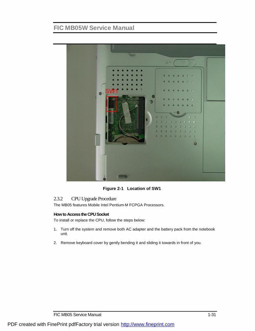
Figure 2-1 Location of SW1
2.3.2 CPU Upgrade Procedure The MB05 features Mobile Intel Pentium-M FCPGA Processors. How to Access the CPU Socket To install or replace the CPU, follow the steps below: 1. Turn off the system and remove both AC adapter and the battery pack from the notebook
unit. 2. Remove keyboard cover by gently bending it and sliding it towards in front of you.
PDF created with FinePrint pdfFactory trial version http://www.fineprint.com

FIC MB05W Service Manual
1-32 FIC MB05 Service Manual
Figure 2-2 Remove keyboard Cover 3. There are two screws on the bottom case and that should be removing as the picture
indicated. 4. Lift the keyboard and tilt it towards the LCD panel. 5. Release keyboard cable by sliding the ZIF connector towards up direction.
Figure 2-3 Remove two screws
PDF created with FinePrint pdfFactory trial version http://www.fineprint.com
FIC MB05W Service Manual
FIC MB05 Service Manual 1-33
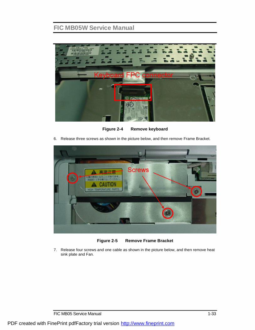
Figure 2-4 Remove keyboard
6. Release three screws as shown in the picture below, and then remove Frame Bracket.
Figure 2-5 Remove Frame Bracket
7. Release four screws and one cable as shown in the picture below, and then remove heat sink plate and Fan.
PDF created with FinePrint pdfFactory trial version http://www.fineprint.com

FIC MB05W Service Manual
1-34 FIC MB05 Service Manual
Figure 2-6 Remove heat sink plate and Fan 8. Use a flat screwdriver to unlock CPU.
Figure 2-7 Remove CPU
PDF created with FinePrint pdfFactory trial version http://www.fineprint.com
FIC MB05W Service Manual
FIC MB05 Service Manual 1-35
9. Remove CPU and insert the preferred CPU. 10. Use a flat screwdriver to lock CPU. 11. Place back the heat plate and keyboard cover. Boot on the computer, and then BIOS will
automatically detect the type of the CPU which just be installed.
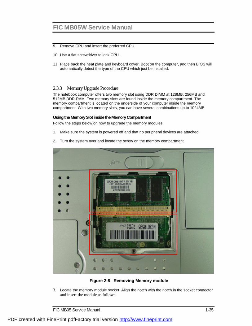
2.3.3 Memory Upgrade Procedure The notebook computer offers two memory slot using DDR DIMM at 128MB, 256MB and 512MB DDR-RAM. Two memory slots are found inside the memory compartment. The memory compartment is located on the underside of your computer inside the memory compartment. With two memory slots, you can have several combinations up to 1024MB. Using the Memory Slot inside the Memory Compartment Follow the steps below on how to upgrade the memory modules: 1. Make sure the system is powered off and that no peripheral devices are attached. 2. Turn the system over and locate the screw on the memory compartment.
Figure 2-8 Removing Memory module 3. Locate the memory module socket. Align the notch with the notch in the socket connector
and insert the module as follows:
PDF created with FinePrint pdfFactory trial version http://www.fineprint.com
FIC MB05W Service Manual
1-36 FIC MB05 Service Manual
− Hold the DIMM at a 60-degree angle and align the DIMM connector with the socket in the system. Push the connector into the socket.
− Press down on the edge of the DIMM until the locking tabs on the sides snap into place, securing the module.
4. To remove a DIMM, press the locking tabs away from the sides of the module until the module pops up. Then, remove the DIMM.
5. Reassemble the notebook components as follows.
− Put the DIMM door back. − Replace the screw and turn the system over.
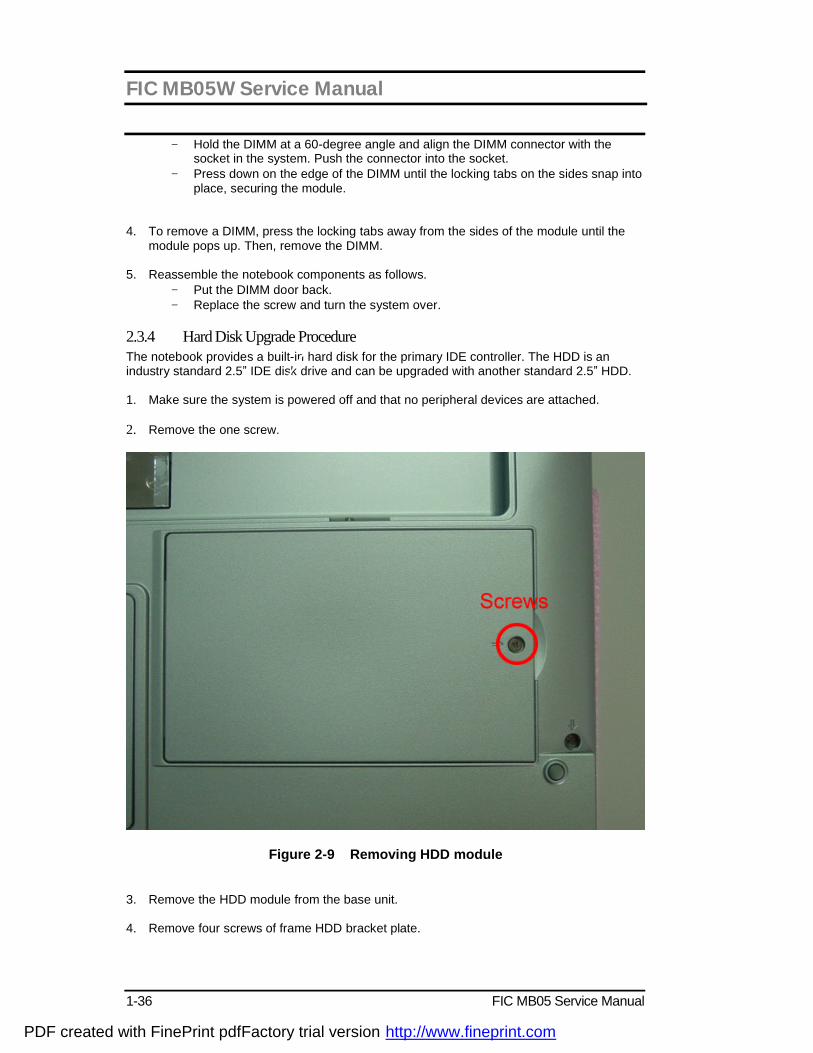
2.3.4 Hard Disk Upgrade Procedure The notebook provides a built-in hard disk for the primary IDE controller. The HDD is an industry standard 2.5” IDE disk drive and can be upgraded with another standard 2.5” HDD. 1. Make sure the system is powered off and that no peripheral devices are attached. 2. Remove the one screw.
Figure 2-9 Removing HDD module
3. Remove the HDD module from the base unit. 4. Remove four screws of frame HDD bracket plate.
PDF created with FinePrint pdfFactory trial version http://www.fineprint.com

FIC MB05W Service Manual
FIC MB05 Service Manual 1-37
Figure 2-10 Screws Locations of the frame HDD bracket plate
2.3.5 System BIOS Upgrade Procedure The notebook supports EPROM Flash BIOS that allows you to easily update the system BIOS using the Phoenix BIOS Flash utility program called “PHLASH.COM”. This program runs under MS-DOS and requires the system not to load high memory like HIMEM.SYS. It also needs the “PLATFORM.BIN” file in order to activate. Follow the steps below on how to update the system BIOS: 1. Prepare a clean bootable diskette without loading the HIMEM.SYS. Copy the files
PHLASH.COM and PLATFORM.BIN into the diskette along with the BIOS ROM file. 2. Restart the computer and boot from the diskette. At the DOS prompt, type the command
“PHLASH <BIOSfile.ROM>” to activate Flash BIOS programming utility. The computer will then start to update the system BIOS inside the notebook.
3. After programming is complete, the system will prompt you to press any key to shutdown
the computer. The BIOS version is displayed inside the BIOS Setup Main menu. Press <F2> after power on to run CMOS Setup program.
BIOS Version : 1.0A-0716-0724
i It is very important not to power off the system whenever the FLASH BIOS program is running. Otherwise, the system may not be able to power on and you need to replace the BIOS EPROM chip from another working notebook.
i Always plug in the AC adapter when updating the BIOS.
PDF created with FinePrint pdfFactory trial version http://www.fineprint.com
FIC MB05W Service Manual
1-38 FIC MB05 Service Manual
3.1 Overview
The MB05 is an IBM PC/AT compatible Notebook PC which supports the Intel uFCPGA Socket. The following are the major features that MB05 supports.
² Microsoft PC2001 logo and WinXP logo approval. ² 14.1”,15” XGA and 15”SXGA+ panel support. ² Support ACPI 1.0B (or above). ² Support PCI 2.2 (or above). ² Support USB 1.1/2.0. ² Support SMBIOS 2.3.(or above)
3.2 Summary of the BIOS Specification The summary of the BIOS specification is as the below description:
PDF created with FinePrint pdfFactory trial version http://www.fineprint.com

FIC MB05W Service Manual
FIC MB05 Service Manual 1-39
Controller Chip Description BIOS Feature § Microsoft PC99 logo and WinXP logo approval.
§ Support Boot Block / Crisis Rescue. § APM 1.2 Compliance § Support ACPI 1.0B (or above) Spec. § Support PCI 2.1 (or above) Spec. § Support SMBIOS 2.3 (or above) Spec § Support Windows XP / Windows 2K. § Support flash function including both DOS and Windows interface for new BIOS update. § Support US keyboard . § Support boot from LAN , USB FDD/FLASH , HDD and CDROM Drive. § Support Phoenix First BIOS.
CPU Auto detecting the CPU type and speed for Intel Banias based system. Support Intel Geyserville III Technology .
DRAM Auto sizing and detection. Support PC-200/266 DDR SDRAM. Cache § Level 2 SRAM auto sizing and detection.
§ Always enable CPU L1 and L2 cache. Shadow Always enable VGA and System BIOS shadow. Display § System auto detects LCD or CRT or TV presence on boot .
§ Up to 32 MB of Dynamic Video Memory Allocation.
Hard Disk § Enhanced IDE spec. § Support auto IDE detection. § Support LBA mode for larger capacity HDD. § Support Ultra DMA 33/66/100. § Support Fast PIO mode 1-4 transfer. § Support 32 bit PIO transfer. § Support Multi-Sector transfer. § Support SMART monitoring.
Multi Boot Allow the user to select boot from USB FDD/FLASH, HDD LAN and CD-ROM.
Plug and Play Support PnP Run Time Service and conflict-free allocation of resource during POST
Smart Battery Support BIOS interface to pass battery information to the application via SMBus.
Keyboard Controller Support Fn hot keys, two Win95 hot keys, built-in Glide Pad. PCMCIA Compliant with PCMCIA 2.1 specification. Power Management Support (ACPI Mode)
The power management is compliant with ACPI 1.0B specification and supports the following power state: § S0 (Full-On) Mode § S3 (STR) Mode § S4 (STD) Mode § S5 (Soft-Off) Mode
PDF created with FinePrint pdfFactory trial version http://www.fineprint.com
FIC MB05W Service Manual
1-40 FIC MB05 Service Manual
3.3 Subsystem Software Functions This section provides introduction on the software functions of the notebook subsystems and BIOS related function.
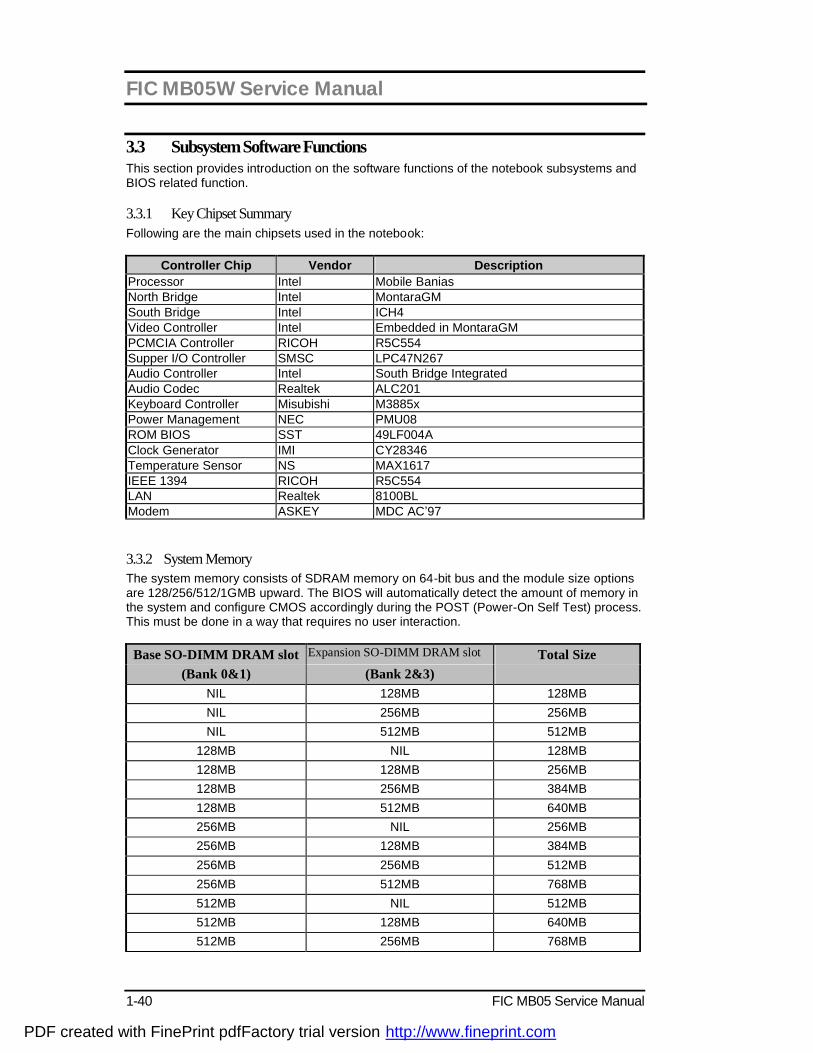
3.3.1 Key Chipset Summary Following are the main chipsets used in the notebook:
Controller Chip Vendor Description Processor Intel Mobile Banias North Bridge Intel MontaraGM South Bridge Intel ICH4 Video Controller Intel Embedded in MontaraGM PCMCIA Controller RICOH R5C554 Supper I/O Controller SMSC LPC47N267 Audio Controller Intel South Bridge Integrated Audio Codec Realtek ALC201 Keyboard Controller Misubishi M3885x Power Management NEC PMU08 ROM BIOS SST 49LF004A Clock Generator IMI CY28346 Temperature Sensor NS MAX1617 IEEE 1394 RICOH R5C554 LAN Realtek 8100BL Modem ASKEY MDC AC’97
3.3.2 System Memory The system memory consists of SDRAM memory on 64-bit bus and the module size options are 128/256/512/1GMB upward. The BIOS will automatically detect the amount of memory in the system and configure CMOS accordingly during the POST (Power-On Self Test) process. This must be done in a way that requires no user interaction.
Base SO-DIMM DRAM slot Expansion SO-DIMM DRAM slot Total Size (Bank 0&1) (Bank 2&3)
NIL 128MB 128MB NIL 256MB 256MB NIL 512MB 512MB
128MB NIL 128MB 128MB 128MB 256MB 128MB 256MB 384MB 128MB 512MB 640MB 256MB NIL 256MB 256MB 128MB 384MB 256MB 256MB 512MB 256MB 512MB 768MB 512MB NIL 512MB 512MB 128MB 640MB 512MB 256MB 768MB
PDF created with FinePrint pdfFactory trial version http://www.fineprint.com

FIC MB05W Service Manual
FIC MB05 Service Manual 1-41
512MB 512MB 1024MB
3.3.3 Video
Supported Video Mode The following is the display modes supported by the INTEL Mobility Video control in
LCD only, CRT only, and simultaneous mode. The VGA BIOS will allow mode sets of resolutions greater than the panel size but only show as much mode display as will fit on the panel.
Supported standard VGA modes: The VGA BIOS supports the IBM VGA Standard 7-bit VGA modes numbers.
Mode Pixel Resolution Colors Memory 00h/01h 40*25 16 Text 02h/03h 80*25 16 Text 04h/05h 320*200 4 2-bit Planar
06h 640*200 2 1-bit Planar 07h 80*25 Mono Text 0Dh 320*200 16 4-bit Planar 0Eh 640*200 16 4-bit Planar 0Fh 640*350 Mono 1-bit Planar 10h 640*350 16 4-bit Planar 11h 640*480 2 2-bit Planar 12h 640*480 16 4-bit Planar 13h 320*200 256 8-bit Planar
Note: All Standard VGA Modes are limited to the standard VGA refresh rates. Supported extended video modes: CRT device will support all listed VESA mode; and other devices such as PANEL & TV may be limited to the mode support due to their characteristics.
VESA Mode
Pixel Resolution
Memory Model Refresh Rates In (Hz) Minimum Memory
100h 640 x 400 8-bit Packed 70 2MB 101h 640 x 480 8-bit Packed 60, 72, 75, 85 2MB 102h 800 x 600 4-bit Planar 60, 72, 75, 85, 100 2MB 103h 800 x 600 8-bit Packed 60, 72, 75, 85, 100 2MB 104h 1024 x 768 4-bit Planar 43(I), 60, 70, 75, 85, 100 2MB 105h 1024 x 768 8-bit Packed 43(I), 60, 70, 75, 85, 100 2MB 106h 1280 x 1024 4-bit Planar 43(I), 60, 75, 85 2MB 107h 1280 x 1024 8-bit Packed 43(I), 60, 75, 85 2MB 10Eh 320 x 200 16-bit Packed 70 2MB
PDF created with FinePrint pdfFactory trial version http://www.fineprint.com
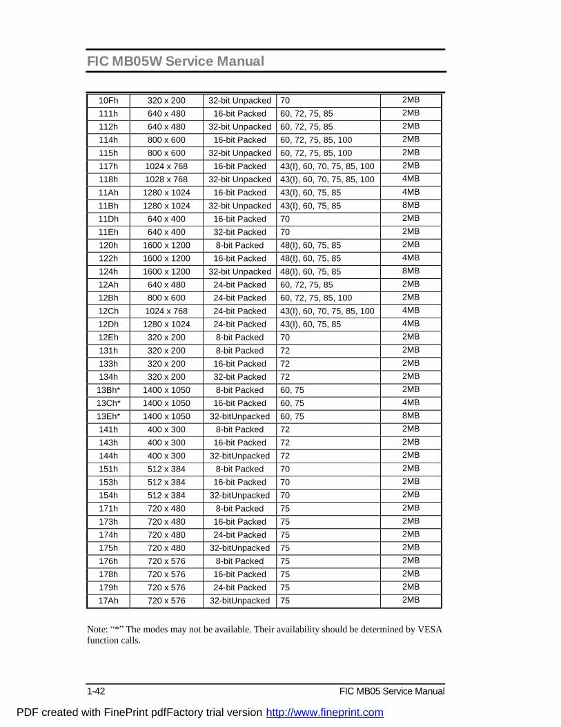
FIC MB05W Service Manual
1-42 FIC MB05 Service Manual
10Fh 320 x 200 32-bit Unpacked 70 2MB 111h 640 x 480 16-bit Packed 60, 72, 75, 85 2MB 112h 640 x 480 32-bit Unpacked 60, 72, 75, 85 2MB 114h 800 x 600 16-bit Packed 60, 72, 75, 85, 100 2MB 115h 800 x 600 32-bit Unpacked 60, 72, 75, 85, 100 2MB 117h 1024 x 768 16-bit Packed 43(I), 60, 70, 75, 85, 100 2MB 118h 1028 x 768 32-bit Unpacked 43(I), 60, 70, 75, 85, 100 4MB 11Ah 1280 x 1024 16-bit Packed 43(I), 60, 75, 85 4MB 11Bh 1280 x 1024 32-bit Unpacked 43(I), 60, 75, 85 8MB 11Dh 640 x 400 16-bit Packed 70 2MB 11Eh 640 x 400 32-bit Packed 70 2MB 120h 1600 x 1200 8-bit Packed 48(I), 60, 75, 85 2MB 122h 1600 x 1200 16-bit Packed 48(I), 60, 75, 85 4MB 124h 1600 x 1200 32-bit Unpacked 48(I), 60, 75, 85 8MB 12Ah 640 x 480 24-bit Packed 60, 72, 75, 85 2MB 12Bh 800 x 600 24-bit Packed 60, 72, 75, 85, 100 2MB 12Ch 1024 x 768 24-bit Packed 43(I), 60, 70, 75, 85, 100 4MB 12Dh 1280 x 1024 24-bit Packed 43(I), 60, 75, 85 4MB 12Eh 320 x 200 8-bit Packed 70 2MB 131h 320 x 200 8-bit Packed 72 2MB 133h 320 x 200 16-bit Packed 72 2MB 134h 320 x 200 32-bit Packed 72 2MB 13Bh* 1400 x 1050 8-bit Packed 60, 75 2MB 13Ch* 1400 x 1050 16-bit Packed 60, 75 4MB 13Eh* 1400 x 1050 32-bitUnpacked 60, 75 8MB 141h 400 x 300 8-bit Packed 72 2MB 143h 400 x 300 16-bit Packed 72 2MB 144h 400 x 300 32-bitUnpacked 72 2MB 151h 512 x 384 8-bit Packed 70 2MB 153h 512 x 384 16-bit Packed 70 2MB 154h 512 x 384 32-bitUnpacked 70 2MB 171h 720 x 480 8-bit Packed 75 2MB 173h 720 x 480 16-bit Packed 75 2MB 174h 720 x 480 24-bit Packed 75 2MB 175h 720 x 480 32-bitUnpacked 75 2MB 176h 720 x 576 8-bit Packed 75 2MB 178h 720 x 576 16-bit Packed 75 2MB 179h 720 x 576 24-bit Packed 75 2MB 17Ah 720 x 576 32-bitUnpacked 75 2MB
Note: “*” The modes may not be available. Their availability should be determined by VESA function calls.
PDF created with FinePrint pdfFactory trial version http://www.fineprint.com
FIC MB05W Service Manual
FIC MB05 Service Manual 1-43
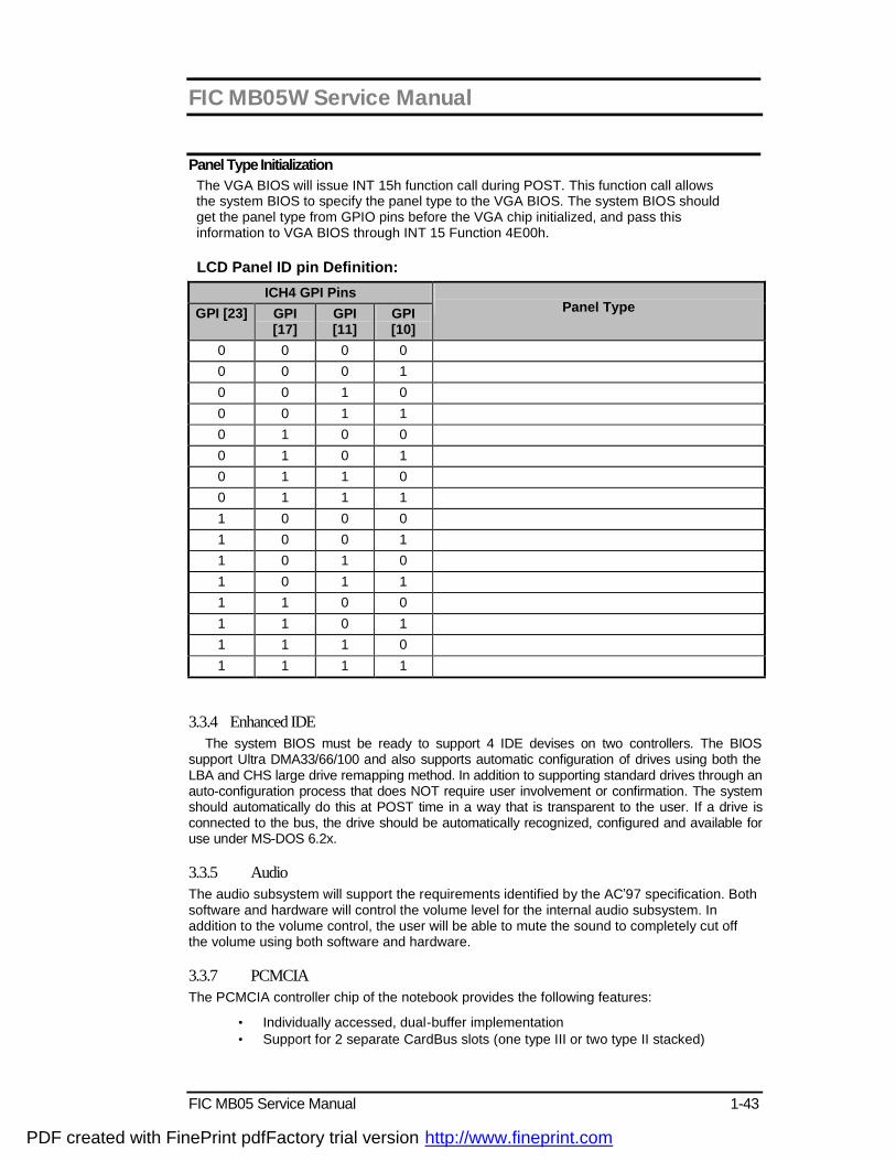
Panel Type Initialization The VGA BIOS will issue INT 15h function call during POST. This function call allows the system BIOS to specify the panel type to the VGA BIOS. The system BIOS should get the panel type from GPIO pins before the VGA chip initialized, and pass this information to VGA BIOS through INT 15 Function 4E00h. LCD Panel ID pin Definition:
ICH4 GPI Pins GPI [23] GPI
[17] GPI [11]
GPI [10]
Panel Type
0 0 0 0 0 0 0 1 0 0 1 0 0 0 1 1 0 1 0 0 0 1 0 1 0 1 1 0 0 1 1 1 1 0 0 0 1 0 0 1 1 0 1 0 1 0 1 1 1 1 0 0 1 1 0 1 1 1 1 0 1 1 1 1
3.3.4 Enhanced IDE The system BIOS must be ready to support 4 IDE devises on two controllers. The BIOS
support Ultra DMA33/66/100 and also supports automatic configuration of drives using both the LBA and CHS large drive remapping method. In addition to supporting standard drives through an auto-configuration process that does NOT require user involvement or confirmation. The system should automatically do this at POST time in a way that is transparent to the user. If a drive is connected to the bus, the drive should be automatically recognized, configured and available for use under MS-DOS 6.2x.
3.3.5 Audio The audio subsystem will support the requirements identified by the AC’97 specification. Both software and hardware will control the volume level for the internal audio subsystem. In addition to the volume control, the user will be able to mute the sound to completely cut off the volume using both software and hardware.
3.3.7 PCMCIA The PCMCIA controller chip of the notebook provides the following features:
• Individually accessed, dual-buffer implementation • Support for 2 separate CardBus slots (one type III or two type II stacked)
PDF created with FinePrint pdfFactory trial version http://www.fineprint.com
FIC MB05W Service Manual
1-44 FIC MB05 Service Manual
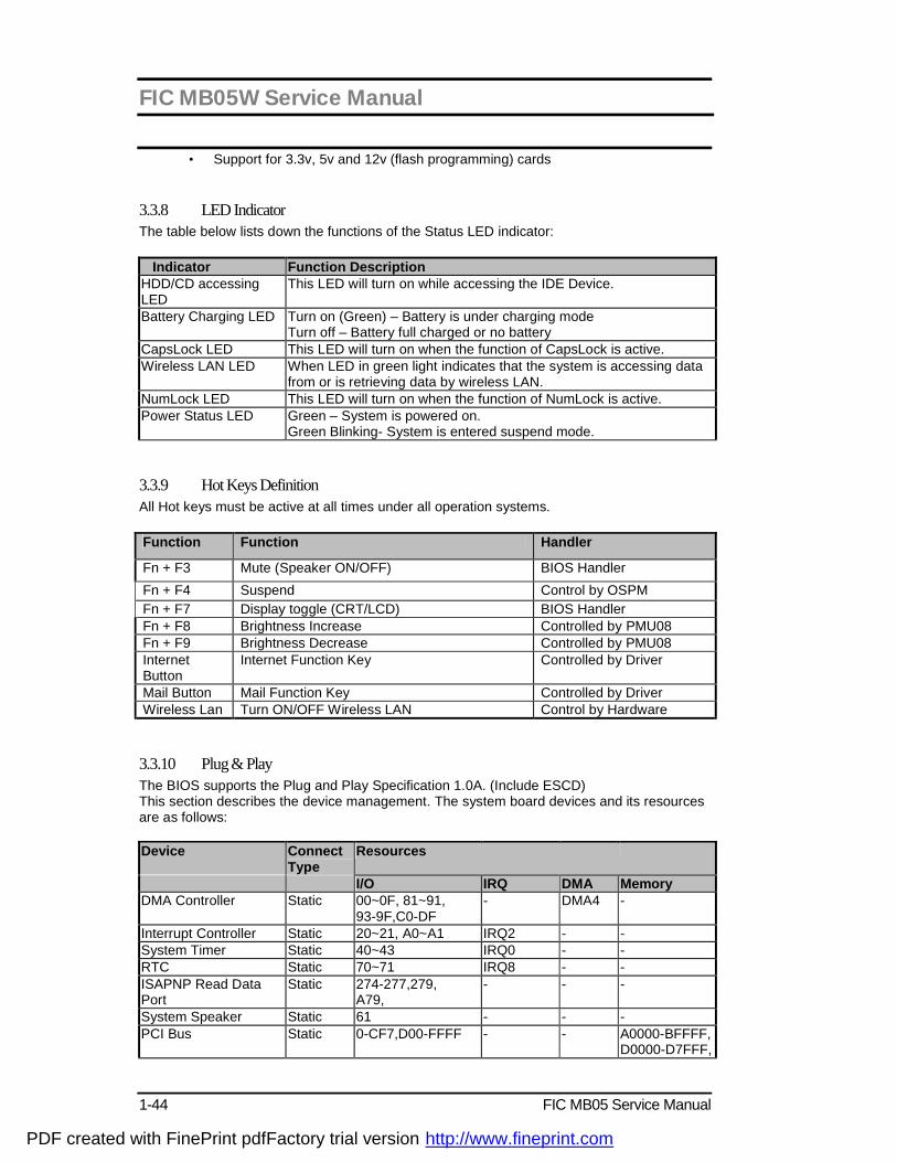
• Support for 3.3v, 5v and 12v (flash programming) cards 3.3.8 LED Indicator The table below lists down the functions of the Status LED indicator: Indicator Function Description HDD/CD accessing LED
This LED will turn on while accessing the IDE Device.
Battery Charging LED Turn on (Green) – Battery is under charging mode Turn off – Battery full charged or no battery
CapsLock LED This LED will turn on when the function of CapsLock is active. Wireless LAN LED When LED in green light indicates that the system is accessing data
from or is retrieving data by wireless LAN. NumLock LED This LED will turn on when the function of NumLock is active. Power Status LED Green – System is powered on.
Green Blinking- System is entered suspend mode.
3.3.9 Hot Keys Definition All Hot keys must be active at all times under all operation systems. Function Function Handler
Fn + F3 Mute (Speaker ON/OFF) BIOS Handler Fn + F4 Suspend Control by OSPM Fn + F7 Display toggle (CRT/LCD) BIOS Handler Fn + F8 Brightness Increase Controlled by PMU08 Fn + F9 Brightness Decrease Controlled by PMU08 Internet Button
Internet Function Key Controlled by Driver
Mail Button Mail Function Key Controlled by Driver Wireless Lan Turn ON/OFF Wireless LAN Control by Hardware 3.3.10 Plug & Play The BIOS supports the Plug and Play Specification 1.0A. (Include ESCD) This section describes the device management. The system board devices and its resources are as follows: Device Connect
Type Resources
I/O IRQ DMA Memory DMA Controller Static 00~0F, 81~91,
93-9F,C0-DF - DMA4 -
Interrupt Controller Static 20~21, A0~A1 IRQ2 - - System Timer Static 40~43 IRQ0 - - RTC Static 70~71 IRQ8 - - ISAPNP Read Data Port
Static 274-277,279, A79,
- - -
System Speaker Static 61 - - - PCI Bus Static 0-CF7,D00-FFFF - - A0000-BFFFF,
D0000-D7FFF,
PDF created with FinePrint pdfFactory trial version http://www.fineprint.com

FIC MB05W Service Manual
FIC MB05 Service Manual 1-45
E0000-E3000, 10000000-FEBFFFFF,
MotherBoard Resource Static 10-1F,24-25,28-29,2C-31,34-35,38-39,3C-3D,5053,72-77,80,A4-A5,A8-A9,AC-AD,B0-B5,B8-B9,BC-BD,4D0-4D1,580-587,1180-11BF,1200,FE00
- - FEC10000-FEC1FFFF, FF000000-FF070000, FF800000-FF870000, FF880000-FF8FFFFF, FF900000-FFBFFFFF, FFF00000-FFFFFFFF
Keyboard Controller Static 60, 64 IRQ1 - - PMU08 Controller Static 68, 6C - - - Math Coprocessor Static F0~FE IRQ13 - - Glide Pad Static - IRQ12 - - Video Controller Static 3B0~3BB,
3C0~3DF, 1800~1807,
IRQ11/IRQ5/IRQ7
- A0000~BFFFF, C0000~CFFFF, E0000000-E00FFFFF, E8000000-EFFFFFFF, F0000000-F7FFFFFF,
Dual IDE Controller Static 170~177, 1F0~1F7, 376,3F6
IRQ14, 15 - -
CardBus Controller Dynamic 3E0~3E1, FD00-FDFF, FF00-FFFF
Cardbus0: IRQ11/IRQ5/IRQ7 Cardbus1: IRQ10/IRQ3/IRQ4
- D7000-D7FFF, FABFD000-FEBFCFFF, FEBFD000-FEBFDFFF, FEBFE000-FEBFEFFF,
Audio chip Dynamic 1880-18BF, 1C00-1CFF
IRQ10/IRQ3/IRQ4
- E0100800-E01008FF, E0100C00-E0100DFF,
Modem Dynamic 2000~207F, 2400-24FF
IRQ10/IRQ3/IRQ4
- -
LAN Dynamic 3000~30FF IRQ10/IRQ3/IRQ4
- E0201800-E02018FF
82801DB/DBM USB Dynamic 1820~185F IRQ11/IRQ5/IRQ7
- -
82801DB/DBM SMBUS
Dynamic 1100~111F IRQ10/IRQ3/IRQ4
- -
82801DB/DBM Ultra ATA
Dynamic 1810~181F - FEBFFC00-FEBFFFF,
ACPI-Compliant system
Dynamic - IRQ9
- -
PDF created with FinePrint pdfFactory trial version http://www.fineprint.com
FIC MB05W Service Manual
1-46 FIC MB05 Service Manual
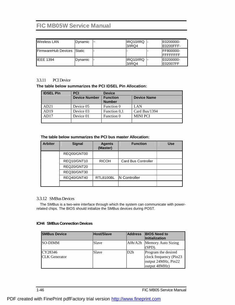
Wireless LAN Dynamic ~ IRQ10/IRQ3/IRQ4
- E0200000-E0200FFF-
FirmwareHub Devices Static - - - FF800000-FFFFFFFF
IEEE 1394 Dynamic - IRQ10/IRQ3/IRQ4
- E0200000-E02007FF
3.3.11 PCI Device The table below summarizes the PCI IDSEL Pin Allocation:
IDSEL Pin PCI Device Device Number Function
Number Device Name
AD21 Device 05 Function 0 LAN AD19 Device 03 Function 0,1 Card Bus/1394 AD17 Device 01 Function 0 MINI PCI
The table below summarizes the PCI bus master Allocation: Arbiter Signal Agents
(Master) Function Use
REQ00/GNT00
REQ10/GNT10 RICOH Card Bus Controller REQ20/GNT20 REQ30/GNT30 REQ40/GNT40 RTL8100BL LAN Controller
3.3.12 SMBus Devices The SMBus is a two-wire interface through which the system can communicate with power-
related chips. The BIOS should initialize the SMBus devices during POST. ICH4 SMBus Connection Devices
SMBus Device Host/Slave Address BIOS Need to Initialization
SO-DIMM Slave A0h/A2h Memory Auto Sizing (SPD).
CY28346 CLK Generator
Slave D2h Program the desired clock frequency (Pin23 output 24MHz, Pin22 output 48MHz)
PDF created with FinePrint pdfFactory trial version http://www.fineprint.com
FIC MB05W Service Manual
FIC MB05 Service Manual 1-47
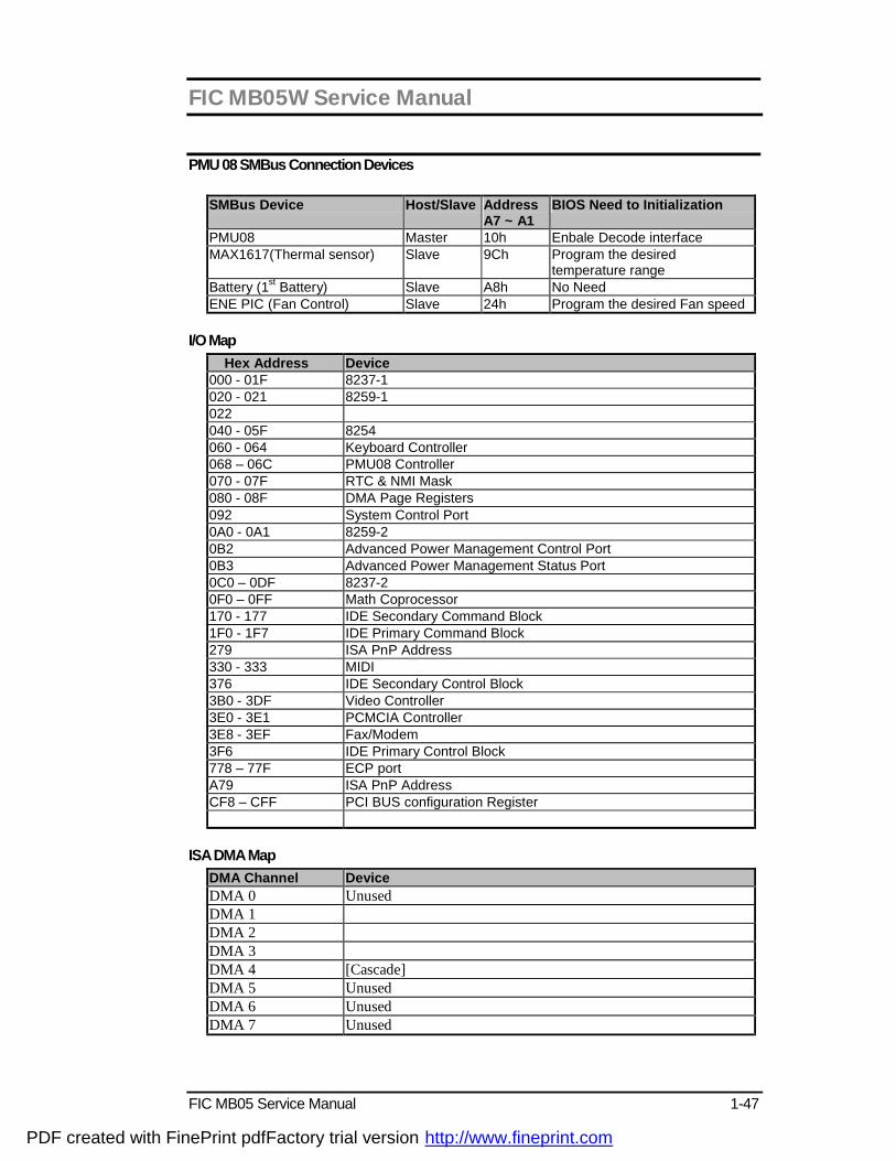
PMU 08 SMBus Connection Devices
SMBus Device Host/Slave Address A7 ~ A1
BIOS Need to Initialization
PMU08 Master 10h Enbale Decode interface MAX1617(Thermal sensor) Slave 9Ch Program the desired
temperature range Battery (1st Battery) Slave A8h No Need ENE PIC (Fan Control) Slave 24h Program the desired Fan speed
I/O Map
Hex Address Device 000 - 01F 8237-1 020 - 021 8259-1 022 040 - 05F 8254 060 - 064 Keyboard Controller 068 – 06C PMU08 Controller 070 - 07F RTC & NMI Mask 080 - 08F DMA Page Registers 092 System Control Port 0A0 - 0A1 8259-2 0B2 Advanced Power Management Control Port 0B3 Advanced Power Management Status Port 0C0 – 0DF 8237-2 0F0 – 0FF Math Coprocessor 170 - 177 IDE Secondary Command Block 1F0 - 1F7 IDE Primary Command Block 279 ISA PnP Address 330 - 333 MIDI 376 IDE Secondary Control Block 3B0 - 3DF Video Controller 3E0 - 3E1 PCMCIA Controller 3E8 - 3EF Fax/Modem 3F6 IDE Primary Control Block 778 – 77F ECP port A79 ISA PnP Address CF8 – CFF PCI BUS configuration Register
ISA DMA Map
DMA Channel Device DMA 0 Unused DMA 1 DMA 2 DMA 3 DMA 4 [Cascade] DMA 5 Unused DMA 6 Unused DMA 7 Unused
PDF created with FinePrint pdfFactory trial version http://www.fineprint.com
FIC MB05W Service Manual
1-48 FIC MB05 Service Manual
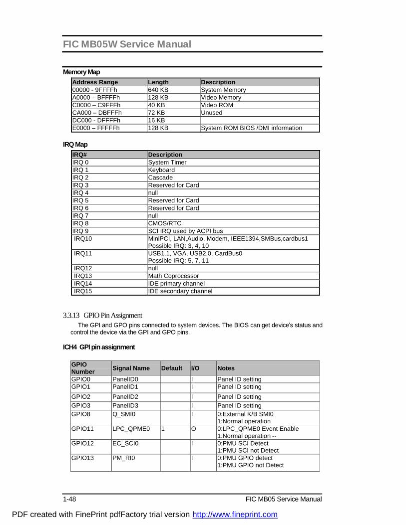
Memory Map Address Range Length Description 00000 - 9FFFFh 640 KB System Memory A0000 – BFFFFh 128 KB Video Memory C0000 – C9FFFh 40 KB Video ROM CA000 – DBFFFh 72 KB Unused DC000 - DFFFFh 16 KB E0000 – FFFFFh 128 KB System ROM BIOS /DMI information
IRQ Map
IRQ# Description IRQ 0 System Timer IRQ 1 Keyboard IRQ 2 Cascade IRQ 3 Reserved for Card IRQ 4 null IRQ 5 Reserved for Card IRQ 6 Reserved for Card IRQ 7 null IRQ 8 CMOS/RTC IRQ 9 SCI IRQ used by ACPI bus IRQ10 MiniPCI, LAN,Audio, Modem, IEEE1394,SMBus,cardbus1
Possible IRQ: 3, 4, 10 IRQ11 USB1.1, VGA, USB2.0, CardBus0
Possible IRQ: 5, 7, 11 IRQ12 null IRQ13 Math Coprocessor IRQ14 IDE primary channel IRQ15 IDE secondary channel
3.3.13 GPIO Pin Assignment The GPI and GPO pins connected to system devices. The BIOS can get device’s status and
control the device via the GPI and GPO pins.
ICH4 GPI pin assignment
GPIO Number Signal Name Default I/O Notes
GPIO0 PanelID0 I Panel ID setting GPIO1 PanelID1 I Panel ID setting GPIO2 PanelID2 I Panel ID setting GPIO3 PanelID3 I Panel ID setting GPIO8
Q_SMI0 I 0:External K/B SMI0 1:Normal operation
GPIO11 LPC_QPME0 1 O 0:LPC_QPME0 Event Enable 1:Normal operation --
GPIO12 EC_SCI0 I 0:PMU SCI Detect 1:PMU SCI not Detect
GPIO13
PM_RI0 I 0:PMU GPIO detect 1:PMU GPIO not Detect
PDF created with FinePrint pdfFactory trial version http://www.fineprint.com

FIC MB05W Service Manual
FIC MB05 Service Manual 1-49
GPIO17 PMUFLASH0 1 O 0:Flash PMU08 Firmware --
GPIO25 CB_HWSUSP0 1 O R5C551 Hardware suspend control pin
GPIO32 SPDMUX0 1 O SMBus select 1
GPIO33
SPDMUX1 1 0 SMBus select 0
3.3.14 PMU08 GPIO pin assignment
GPIO number
Signal Name Default I/O Notes Remark
GPIO B6 PM_SLP_S10 1 I Suspend Plane A control for ICH4 0: POS, STR and STD suspend state. 1: not suspend state.
GPIO B5 N.C. -- -- No used
GPIO B4 N.C. -- -- No used GPIO B1 N.C. 1 O No used GPIO B0 N.C. -- -- No use GPIO A7 RI10 1 I RS Ring event
0: Ring 1: No Ring
GPIO A6 PCMRI0 1 I PC Card Ring event 0: Ring 1: No Ring
GPIO A0 LID0 1 I LCD Open/Close Status 0: LCD Close 1: LCD Open
GPIO C1 NC -- -- No Use GPIO B7 PM_RI0 1 O Wake Up event request
0: Wake SMI(SCI) 1: There is no demand.
GPIO B3 PDCOM0 1 O SHUTDOWN MAX3243 1:NO SHUTDOWN 0: SHUTDOWN
GPIO B2 N.C. -- - No Use GPIO B0 N.C. -- -- No Use GPIO A5 PRSTMSK0 1 O PCI Reset Mask
0: Reset Mask 1: Reset Enable
GPIO A4 PCMUTE0 1 O Mute PC Speaker GPIO A2 MAILLED0 1 O MAIL ARRIVAL INDICATE GPIO A1 N.C. -- -- No use GPIO C2 CHGLED Charge Battery indicator :
1 : charging Battery 0 : Stop charging Battery
GPIO C3 N.C. -- -- No Use
GPIO C0 N.C. -- -- No Use
PDF created with FinePrint pdfFactory trial version http://www.fineprint.com
FIC MB05W Service Manual
1-50 FIC MB05 Service Manual
3.4 ACPI
General Requirements The BIOS must meet the following general Power Management requirements: Refers to the portion of the firmware that is compatible with the ACPI 1.0b specifications. Support for Power ON(S0 state), Suspend-to-RAM (S3 state) , Suspend-to-Disk mode (S4 state) and Soft OFF(S5 state).
Global System State Definitions Global system states (Gx states) apply to the entire system and are visible to the user. Following is a list of the system states: G0/S0 - Working:
A computer state where the system dispatches user mode (application) threads and they execute. In this state, devices (peripherals) are dynamically having their power state changed. The user will be able to select (through some user interface) various performance/power characteristics of the system to have the software optimize for performance or battery life. The system responds to external events in real time. It is not safe to disassemble the machine in this state.
G1 - Sleeping: A computer state where the computer consumes a small amount of power, user mode
threads are not being executed, and the system “appears” to be off (from an end user’s perspective, the display is off, etc.). Latency for returning to the Working state varies on the wakeup environment selected prior to entry of this state (for example, should the system answer phone calls, etc.). Work can be resumed without rebooting the OS because large elements of system context are saved by the hardware and the rest by system software. It is not safe to disassemble the machine in this state.
G2/S5 - Soft Off: A computer state where the computer consumes a minimal amount of power. No user
mode or system mode code is run. This state requires a large latency in order to return to the Working state. The system’s context will not be preserved by the hardware. The system must be restarted to return to the Working state. It is not safe to disassemble the machine.
G3 – Mechanical Off:
A computer state that is entered and left by a mechanical means. It is implied by the entry of this off state through a mechanical means that the no electrical current is running through the circuitry and it can be worked on without damaging the hardware or endangering the service personnel. The OS must be restarted to return to the Working state. No hardware context is retained. Except for the real time clock, power consumption is zero.
Sleeping State Definitions Sleeping states (Sx states) are types of sleeping states within the global sleeping state,
G1. The Sx states are briefly defined below. For a detailed definition of the system behavior within each Sx state, refer to ACPI specification section 7.5.2. For a detailed definition of the transitions between each of the Sx states, refer to ACPI specification section 9.1.
S1 Sleeping State:
The S1 sleeping state is a low wake-up latency sleeping state. In this state, no system context is lost (CPU or chip set) and hardware maintains all system context.
PDF created with FinePrint pdfFactory trial version http://www.fineprint.com
FIC MB05W Service Manual
FIC MB05 Service Manual 1-51
S3 Sleeping State:
The S3 sleeping state is a low wake-up latency sleeping state where all system context is lost except system memory. CPU, cache, and chip set context are lost in this state. Hardware maintains memory context and restores some CPU and L2 configuration context. Control starts from the processor’s reset vector after the wake-up event.
S4 Sleeping State:
The S4 sleeping state is the lowest power, longest wake-up latency sleeping state supported by ACPI. In order to reduce power to a minimum, it is assumed that the hardware platform has powered off all devices. Platform context is saved in disk.
S5 Soft Off State:
The S5 state is similar to the S4 state except the OS does not save any context nor enable any devices to wake the system. The system is in the “SOFT” off state and requires a complete boot when awakened. Software uses a different state value to distinguish between the S5 state and the S4 state to allow for initial boot operations within the BIOS to distinguish whether or not the boot is going to wake from a saved memory image.
System Power Plane The system components are grouped as the following parties to let the system to control the
On/Off of power under different power management modes.
3.4.1 System Power Plane The system components are grouped as the following parties to let the system to control the On/Off of power under different power management modes. The power plane is divided as following: Power Group Power
Control Pin
Controlled Devices
+B Nil IMM, (9V~20V) +3VA Nil RTC I/F, PMU08 +12V PWRON PCMCIA Card, AC97 Codec +5V PWRON PCMCIA Slot 5V +3V PWRON VGA, PCMCIA, PCMCIA Slot 3V, DRAM, Twister(DRAM I/F),
M3885x, MAX3243 +5VS SUSB# FLASH ROM, HDD, CD-ROM, USB, Internal K/B, Glide Pad,
Audio AMP, Fan +3VS SUSB# ISA I/F Power, Clock Generator & Buffer (W137) +RTCVCCS Nil RTC 3.4.2 Power Management Mode Transition Flow Chart From a user-visible level, the system can be thought of as being one of the states in the following diagram:
PDF created with FinePrint pdfFactory trial version http://www.fineprint.com

FIC MB05W Service Manual
1-52 FIC MB05 Service Manual
SLP_TYPx=S1and
SLP_EN
S1Sleeping
S2Sleeping
S3Sleeping
SLP_TYPx=S5and
SLP_ENor
PWRBTN_OR
WakeEvent
S4Sleeping
ACPIBoot
(SCI_EN=1)
G2 (S5) -Soft Off
SLP_TYPx=S2and
SLP_EN
SLP_TYPx=S3and
SLP_EN
SLP_TYPx=S4and
SLP_EN
G0 (S0) -Working
G1
S4BIOS_REQto
SMI_CMD
OEM S4 BIOSHandler
SLP_TYPx=S4and
SLP_EN
3.4.3 Power States transition event The following table summarizes the entry events and wake-up events of each power: The following table summarize the entry events and wake-up events of each power state Power State Entry Event Wake up Event S3 OSPM control
Lid Close Power Button Sleep Button Battery Low
Power Button Ring Wake up RTC Alarm LAN Wake Up Lid open
S4 OSPM control, Power button Sleep button Lid Close Battery Low
Power Button RTC Alarm
S5 Power Button Battery Low OSPM control
Power Button
x OSPM: OS-directed Power Management
PDF created with FinePrint pdfFactory trial version http://www.fineprint.com

FIC MB05W Service Manual
FIC MB05 Service Manual 1-53
Device Power Control Methodology Power state of local devices table
This section illustrates the power control status of each key device/component of the system under each power management mode.
PowerState Component
Doze Stand By STR STD/SOff
CPU Stop Grant
Stop Clock Power Off Power Off
L2 CACHE ON Power Down Power Off Power Off MontaraGM ON Stop Clock Power Off (except Vcc) Power Off ICH4 ON ON Power Off (except
SUSVcc, RTCVcc ) Power Off (except SUSVcc, RTCVcc)
DRAM ON Self Refresh Self Refresh Power Off Clock Synthesizer ON Low Power Power Off Power Off CDROM ON Power Down Power Off Power Off HDD ON Power Down Power Off Power Off FDD ON Power Down Power Off Power Off KBC ON ON Power Down Power Off PMU08 ON ON Power Down Power Down VGA/VRAM ON Power Down Power Down Power Off PCMCIA ON Power Down Power Down Power Off AUDIO ON Power Down Power Off Power Off Audio AMP ON Power Down Power Off Power Off LCD Backlight ON Power Off Power Off Power Off LAN ON Power Down Power Down Power Down Internal Modem ON Power Down Power Down Power Down Device Power control Methodology During S3 Mode
This section illustrates the control methodology of each device/component and its details under Stand by mode.
Device Power Down Controlled by Description CPU Hardware Controlled by SUSB# pin L2 CACHE Hardware Power off ICH4 Hardware Controlled by SUSB# pin DRAM Software Self Refresh Clock Synthesizer Hardware Controlled by SUSB# pin CDROM Hardware Power off HDD Hardware Power off FDD Hardware Power off KBC Software Controlled by M3885xM8 power
down command PMU08 Sofeware Controlled by PMU08 power down
command VGA/VRAM Software Controlled by MontaraGM PCMCIA Software Controlled by SUSB# pin AUDIO Hardware Controlled by ICH4 Audio AMP Hardware Controlled by BIOS LCD Backlight Hardware Power off IR Module Hardware Controlled by SUSB# pin LAN Hardware Controlled by Driver enter Dx status Internal Modem Hardware Controlled by Driver enter Dx ststus
PDF created with FinePrint pdfFactory trial version http://www.fineprint.com

FIC MB05W Service Manual
1-54 FIC MB05 Service Manual
Power Button The function of Lid Switch is depends on the ACPI aware OS.
Lid Switch (Cover Switch) The function of Lid Switch is depends on the ACPI aware OS.
3.4.4 Expanding Event Through the Embedded Controller The following figure shows the relationships between the devices that are wired to the embedded controller, the embedded controller queries, and ACPI general
Figure 3-2 The Relationships between ACPI, Controller, and Device SCI Source and GPE Event from PMU08 The system will issue a beep to inform user while the following SCI alerted: PMU08 Input Event GPE Event Handler ADPIN# AC Plug In/Out GPI12 AML Handler BAT0# Battery Plug In/Out GPI12 AML Handler GPIOA0 LID Event GPI13 AML Handler GPIOA3 Keyboard SMI GPI8 AML Handler GPIOA6 PCMCIA Ring In GPI13 AML Handler GPIOA7 COM Port Ring In GPI13 AML Handler THRM Thermal Event GPI12 AML Handler
PDF created with FinePrint pdfFactory trial version http://www.fineprint.com
FIC MB05W Service Manual
FIC MB05 Service Manual 1-55
Control Method Battery Subsystem EC should support all the battery information to ACPI-OS
− Designed Battery capacity − Designed Voltage − Designed Low battery capacity − Designed Low – Low battery capacity − Latest Full charged capacity − Present Remaining capacity − Present drain rate − Present voltage − Present Battery Status
ACPI BIOS should support an independent device object in the name space, and implement the following methods. 3.4.5 Thermal Control
There are primary cooling policies that the OS use to control the thermal state of the hardware
Cooling Policy Action Temperature Setting Active cooling Fan Low On Over 60oC Fan Low Off Below 50oC Active cooling Fan High On Over 75 oC Fan High Off Below 65oC Passive cooling Throttling CPU On Over 85 oC Throttling CPU Off Below 80oC Critical trip point System Shutdown Over 95 oC
3.5 Battery Management
3.5.1 Battery Sub-system § The charger will stop charge the battery when the following condition is detected.
- The temperature of the system is too high - The remaining capacity is 95% and more.
Note that the battery life is depending on different configuration running. E.g. with CD-ROM battery life is shorter, document keyin only battery life is longer, PMU disable battery life is short, PMU enable battery life is longer.
- Battery reading methodology is through PMU08 SMBus.
3.5.2 Battery Low When the battery voltage is approaching to the Low level, the PMU08 will generate a
PDF created with FinePrint pdfFactory trial version http://www.fineprint.com

FIC MB05W Service Manual
1-56 FIC MB05 Service Manual
battery low SMI. The system will do the following action. 1) The Power Indicator will become blinking.
2) The system will issue a Warning beep.
3.5.3 Battery Low - Low When the battery voltage is approaching to the Low-Low level, the PMU08 will generate a battery low-low SMI. The system will do the following action.
1) The Power Indicator will keep on Blinking. 2) The system will enter Suspend To Disk mode even the power management is disabled. The
function of power-on or Resume will be inhibited until the battery Low – Low condition is removed.
3.5.4 AC Adapter When plug in the AC adapter, the system will do the following action: - The charger will charge the Main Battery, if remaining capacity is not full. - The Battery Charging Indicator will turn on if the battery is in changing mode.
3.6 PMU08 The Embedded controller PMU08 acts as a supplement for power management control. It supports a lot of functions via SMBus interface.
3.6.1 The System EC RAM with PMU08 Embedded Controller Command Set The EC I/F command set allows the OS to communicate with the PMU08. For detail information refer to ACPI 1.0B specification.
EC I/F Command
Command Byte Encoding
Byte Register R/W Description Interrupt
#1 EC_SC W Command byte Header
Interrupt on IBF=0
#2 EC_DATA
W Address byte to read
No Interrupt
Read Embedded Controller
(RD_EC)
0x80
#3 EC_DATA
R Read data to host
Interrupt on OBF=1
#1 EC_SC W Command byte Header
Interrupt on IBF=0
#2 EC_DATA
W Address byte to write
Interrupt on IBF=0
Write Embedded Controller
(WR_EC)
0x81
#3 EC_DATA
W Data to write Interrupt on IBF=0
PDF created with FinePrint pdfFactory trial version http://www.fineprint.com

FIC MB05W Service Manual
FIC MB05 Service Manual 1-57
#1 EC_SC W Command byte Header
No Interrupt Burst Enable Embedded Controller
(BE_EC)
0x82
#2 EC_DATA
R Burst acknowledge byte
Interrupt on OBF=1
Burst Disable Embedded Controller
(BD_EC)
0x83 #1 EC_SC W Command byte Header
Interrupt on IBF=0
#1 EC_SC W Command byte Header
No Interrupt Query Embedded Controller
(QR_EC)
0x84
#2 EC_DATA
R Query value to host
Interrupt on OBF=1
3.6.2 PMU08 EC RAM List The micro controller PMU08 acts as a supplement for power management control. It supports the following functions via SMBus Command ( 0x80 , 0xC0 )
Register Bit Number Functi
on Addres
s Name
R/W 7 6 5 4 3 2 1 0
Logic
Default Description
00h *3
Power unit R(/W) DATA[15:0] *1 - 0xffff
0x0000: mWh [Fixed value] 0xffff: Unknown
02h *3
Design capacity
R(/W) DATA[15:0] *1 - 0xffff 0x0000-0xfffe(mWh) 0xffff: Unknown
04h *3
Last Full Charge Capacity
R(/W) DATA[15:0] *1 - 0xffff 0x0000-0xfffe(mWh) 0xffff: Unknown
06h *3
Battery Technology
R(/W) DATA[15:0] *1 - 0xffff
0x0000 : Primary 0x0001: Secondary [Fixed value] 0xffff: Unknown.
1st Battery [ _BIF ]
08h *3
Design Voltage
R(/W) DATA[15:0] *1 - 0xffff 0x0000-0xfffe(mV) 0xffff: Unknown
PDF created with FinePrint pdfFactory trial version http://www.fineprint.com

FIC MB05W Service Manual
1-58 FIC MB05 Service Manual
Register Bit Number Functi
on Addres
s Name
R/W 7 6 5 4 3 2 1 0
Logic
Default Description
0Ah *3
Design capacity of Warning
R(/W) DATA[15:0] *1 - 0xffff 0x0000-0xfffe(mWh) 0xffff: Unknown
0Ch *3
Design capacity of Low
R(/W) DATA[15:0] *1 - 0xffff 0x0000-0xfffe(mWh) 0xffff: Unknown
0Eh *3
Battery capacity Granularity 1
R(/W) DATA[15:0] *1 - 0xffff 0x0000-0xfffe(mWh) 0xffff: Unknown
10h *3
Battery capacity Granularity 2
R(/W) DATA[15:0] *1 - 0xffff 0x0000-0xfffe(mWh) 0xffff: Unknown
12h *3
Model number
R(/W) DATA[15:0] *1 - 0xffff 0x0000 [Not support]
14h *3
Serial Number
R(/W) DATA[15:0] *1 - 0xffff 0x0000 [Not support]
16h *3
Battery type R(/W)
DATA[15:8] *1
All bits are 0
CELL_TYPE [7:0]
- 0xffff
CELL_TYPE [3:0] This code depends on battery data format. In the future, this code may be added. 0x00: NiMH 0x01: Li-ion 0x10: Non-rechargeable battery (Reserved)
PDF created with FinePrint pdfFactory trial version http://www.fineprint.com

FIC MB05W Service Manual
FIC MB05 Service Manual 1-59
Register Bit Number Functi
on Addres
s Name
R/W 7 6 5 4 3 2 1 0
Logic
Default Description
18h *3
OEM Information
R(/W)
DATA [15:8]
*1 All bits are 0
Vender [7:0] - 0xffff
Vender [7:0] This code depends on battery data format. And the following name should be described in the ASL with the same character code. In the future, these codes will be added. 0: “MoliEnergy” 1: “Panasonic” 2: “” (SANYO does not agree the vender name display) 3: “TBCL” (Toshiba) 4: “Sony”
1Ah *3
Battery State
R (/W)
DATA[15:3] *1
All bits are 0
C R I T
C H G
DCHG
- - DCHG=1: CHG =1: CRIT =1:
The battery is discharged The battery is charged The battery is critical (Empty)
1Ch *3
Battery Present rate
R (/W) DATA[15:0] *1 - 0xffff
0x0000-0xfffe(mW) 0xffff: Unknown
1Eh *3
Battery Remaining Capacity
R (/W) DATA[15:0] *1 - 0xffff
0x0000-0xfffe(mWh) 0xffff: Unknown
1st Battery [ _BST
]
20h *3
Battery present Voltage
R (/W) DATA[15:0] *1 - 0xffff
0x0000-0xfffe(mV) 0xffff: Unknown
1st Battery [ _BTP
]
22h Battery Trip Point
R/W DATA[15:0] *1 - 0x0000
0x0000: Clear the trip point 0x0001-0xffff(mWh)
2nd Battery [ _BIF ]
24h to
3Ch *3
*2 *2 *2 *2 *2 *2
2nd 3Eh *2 *2 *2 *2 *2 *2
PDF created with FinePrint pdfFactory trial version http://www.fineprint.com
FIC MB05W Service Manual
1-60 FIC MB05 Service Manual
Register Bit Number Functi
on Addres
s Name
R/W 7 6 5 4 3 2 1 0
Logic
Default Description
Battery [ _BST
]
to 44h *3
2nd Battery [ _BTP
]
46h *2 *2 *2 *2 *2 *2
-
48h Battery data Size
R (/W) DATA [7:0] - -
0x01: DATA size is 3byte.(PMU06A) 0x00: DATA size is 2 byte. (PMU06) *8
49h Design capacity
R (/W) DATA [23:16] *1 *7 - 0xff PMU06A use this data
with 02/03h. *7 *8 1st
Battery [_BIF]
4Ah
Last Full
Charge Capaci
ty
R (/W) DATA [23:16] *1 *7 - 0xff PMU06A use this data
with 04/05h. *7 *8
1st Battery [_BST]
4Bh
Battery Remaining Capacity
R (/W) DATA [23:16] *1 *7 - 0xff PMU06A use this data
with 1E/1Fh. *7 *8
1st Battery [_BTP]
4Ch Battery Trip Point
R (/W) DATA [23:16] *1 *7 - 0x00 PMU06A use this data
with 22/23h. *7 *8
4Dh Design capacity
R (/W) DATA [23:16] *1 *7 - 0xff PMU06A use this data
with 26/27h. *7 *8 2nd
Battery [_BIF]
4Eh
Last Full
Charge Capaci
ty
R/(/W) DATA [23:16] *1 *7 - 0xff PMU06A use this data
with 28/29h. *7 *8
2nd Battery [_BST]
4Fh
Battery Remaing Capacity
R (/W) DATA [23:16] *1 *7 - 0xff PMU06A use this data
with 42/43h. *7 *8
2nd Battery [_BTP]
50h Battery Trip Point
R (/W) DATA [23:16] *1 *7 0x00 PMU06A use this data
with 46/47h. *7 *8
51h to
6Bh
Reserved R/W Don’t care - -
PDF created with FinePrint pdfFactory trial version http://www.fineprint.com

FIC MB05W Service Manual
FIC MB05 Service Manual 1-61
Register Bit Number Functi
on Addres
s Name
R/W 7 6 5 4 3 2 1 0
Logic
Default Description
*3
6Ch PMU_LOW_ ADR
R/W DATA [7:0] - -
6Dh PMU_HIG_ ADR
R/W DATA [15:8] - -
6Eh CHEC
K_ SUM
R/W DATA [7:0] - -
PMU Access
6Fh PMU_DATA R/W DATA [7:0] - -
These registers are available when PMU slave mode or charger mode is selected. For detail information, refer to PMU slave communication section in this document
70h *7
SMB_PTCL R/W PROTOCOL [7:0] - -
71h *7
SMB_STS R/W
D O N E
A L R M
R E S
STATUS [4:0]
- -
72h SMB_ADDR R/W
ADDRESS [6:0]
RES
- -
73h SMB_CMD R/W COMMAND - -
74h to
93h
SMB_DATA [0-31]
R/W DATA - -
94h SMB_BCNT R/W RES
[7:5] BCNT [4:0] - -
95h
SMB_ ALARM_ ADDR
R (/W) ADDRESS [6:0]
RES
- -
96h to
97h
AMB_ ALARM_ DATA [0-1]
R (/W) DATA - -
For detail information, refer to ACPI 1.0 specification [13.9 SMBus Host controller Interface via Embedded controller] These registers are not available when PMU slave mode or charger mode is selected. The PMU06 has access protect function for the EEPROM in the battery, to cancel the protection, set the access protect cancel bit. For detail, refer to SMBus section
SMBus
98h SMB_CNRL R/W RES [7:1]
PRT
0x00 PRT =1:
TheSMBus address (A8-AE) protection is cancelled.
Reserv 99h Reserv R/W Don't care - -
PDF created with FinePrint pdfFactory trial version http://www.fineprint.com

FIC MB05W Service Manual
1-62 FIC MB05 Service Manual
Register Bit Number Functi
on Addres
s Name
R/W 7 6 5 4 3 2 1 0
Logic
Default Description
ed to 9Fh
ed
6Ch PMU_LOW_ ADR
R/W DATA [7:0] - -
6Dh PMU_HIG_ ADR
R/W DATA [15:8] - -
6Eh CHEC
K_ SUM
R/W DATA [7:0] - -
PMU Access
6Fh PMU_DATA R/W DATA [7:0] - -
These registers are available when PMU slave mode or charger mode is selected. For detail information, refer to PMU slave communication section in this document
70h *7
SMB_PTCL R/W PROTOCOL [7:0] - -
71h *7
SMB_STS R/W
D O N E
A L R M
R E S
STATUS [4:0]
- -
72h SMB_ADDR R/W
ADDRESS [6:0]
RES
- -
73h SMB_CMD R/W COMMAND - -
74h to
93h
SMB_DATA [0-31]
R/W DATA - -
94h SMB_BCNT R/W RES
[7:5] BCNT [4:0] - -
95h
SMB_ ALARM_ ADDR
R (/W) ADDRESS [6:0]
RES
- -
96h to
97h
AMB_ ALARM_ DATA [0-1]
R (/W) DATA - -
For detail information, refer to ACPI 1.0 specification [13.9 SMBus Host controller Interface via Embedded controller] These registers are not available when PMU slave mode or charger mode is selected. The PMU06 has access protect function for the EEPROM in the battery, to cancel the protection, set the access protect cancel bit. For detail, refer to SMBus section
SMBus
98h SMB_CNRL R/W RES [7:1]
PRT
0x00 PRT =1:
TheSMBus address (A8-AE) protection is cancelled.
PDF created with FinePrint pdfFactory trial version http://www.fineprint.com
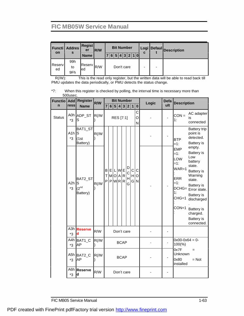
FIC MB05W Service Manual
FIC MB05 Service Manual 1-63
Register Bit Number Functi
on Addres
s Name
R/W 7 6 5 4 3 2 1 0
Logic
Default Description
Reserved
99h to
9Fh
Reserved R/W Don't care - -
R(/W): This is the read only register, but the written data will be able to read back till PMU updates the data periodically, or PMU detects the status change.
*7: When this register is checked by polling, the interval time is necessary more than
500usec. Register Bit Number Functio
n Address Name
R/W 7 6 5 4 3 2 1 0
Logic Default Description
A0h *3
ADP_STS
R(/W) RES [7:1]
C O N
- - CON = 1:
AC adapter is connected
A1h *3
BAT1_STS (1st Battery)
R(/W) - -
A2h *3
BAT2_STS (2nd Battery)
R(/W)
B T P
E M P
L O W
W A R
E R R
D C H G
C H G
C O N
- -
BTP =1: EMP =1: LOW =1: WAR=1: ERR =1: DCHG=1: CHG=1: CON=1:
Battery trip point is detected. Battery is empty. Battery is Low battery state. Battery is Warning state. Battery is Error state. Battery is discharged. Battery is charged. Battery is connected.
A3h *3
Reserved R/W Don’t care - -
A4h *3
BAT1_CAP
R(/W) BCAP - -
A5h *3
BAT2_CAP
R(/W) BCAP - -
0x00-0x64 = 0-100(%) 0x7F = Unknown 0x80 = Not installed
Status
A6h *3
Reserved R/W Don’t care - -
PDF created with FinePrint pdfFactory trial version http://www.fineprint.com
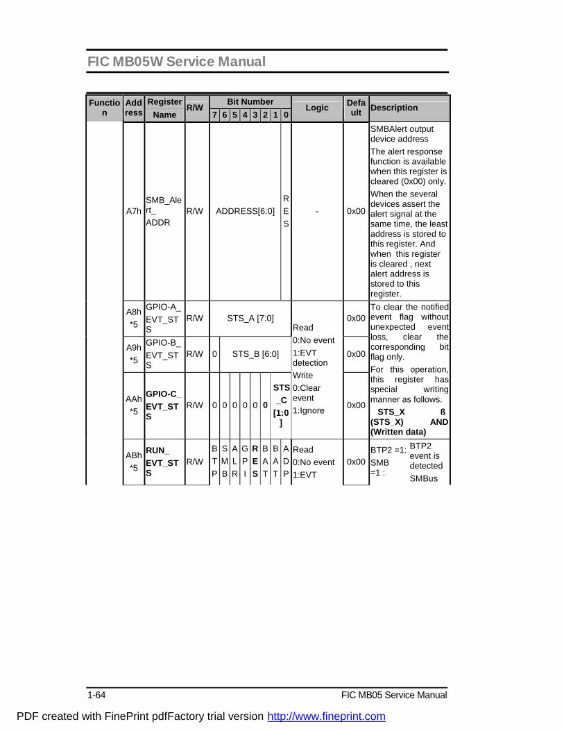
FIC MB05W Service Manual
1-64 FIC MB05 Service Manual
Register Bit Number Function
Address Name
R/W 7 6 5 4 3 2 1 0
Logic Default Description
A7h SMB_Alert_ ADDR
R/W ADDRESS[6:0] R E S
- 0x00
SMBAlert output device address The alert response function is available when this register is cleared (0x00) only. When the several devices assert the alert signal at the same time, the least address is stored to this register. And when this register is cleared , next alert address is stored to this register.
A8h *5
GPIO-A_ EVT_STS
R/W STS_A [7:0] 0x00
A9h *5
GPIO-B_ EVT_STS
R/W 0 STS_B [6:0] 0x00
AAh *5
GPIO-C_ EVT_STS
R/W 0 0 0 0 0 0
STS _C
[1:0]
Read 0:No event 1:EVT detection Write 0:Clear event 1:Ignore 0x00
To clear the notified event flag without unexpected event loss, clear the corresponding bit flag only. For this operation, this register has special writing manner as follows. STS_X ß (STS_X) AND (Written data)
ABh *5
RUN_ EVT_STS
R/W B T P
S M B
A L R
G P I
R E S
B A T
B A T
A D P
Read 0:No event 1:EVT
0x00 BTP2 =1: SMB =1 :
BTP2 event is detected SMBus
PDF created with FinePrint pdfFactory trial version http://www.fineprint.com

FIC MB05W Service Manual
FIC MB05 Service Manual 1-65
Register Bit Number Function
Address Name
R/W 7 6 5 4 3 2 1 0
Logic Default Description
ACh *5
WAKE_ EVT_STS
R/W
2 T O 2 1 detection Write 0:Clear event 1:Ignore
0x00
ALRT=1 : GPIO =1 : BATn=1 : ADP =1 : TH =1 : HIGH=1 : LOW =1 : ERR =1 :
event is detected. SMBAlert is detected. GPIO event is detected. Battery event is detected. Battery event is detected. Thermal event is detected High alarm point is detected. Low alarm point is detected. Polling communication failure with retry.
ADh *5
RUN_ EVT_STS_2
R/W Reserved [7:1] T H
0x00
AEh *5
WAKE EVT_STS_2
R/W Reserved [7:1] T H
0x00
AFh *5
THERMAL_EVT_STS
R/W Reserved [7:3]
E R R
L O W
H I G H
0x00
To clear the notified event flag without unexpected event loss, clear the corresponding bit flag only. For this operation, this register has special writing manner as follows. STS_X ß (STS_X) AND (Written data)
B0h EC_RUN_ ENB
R/W 0: Disable 1: Enable
0x00 Event/ GPIO
Control
B1h EC_WAKE_ ENB
R/W
B T P 2
S M B
A L R T
RES[4:1]
A DP 0: Disable
1: Enable 0x00
BTP2: SMB : ALRT: ADP:
BTP2 event SMBus event. SMBAlert event. Adapter event.
PDF created with FinePrint pdfFactory trial version http://www.fineprint.com
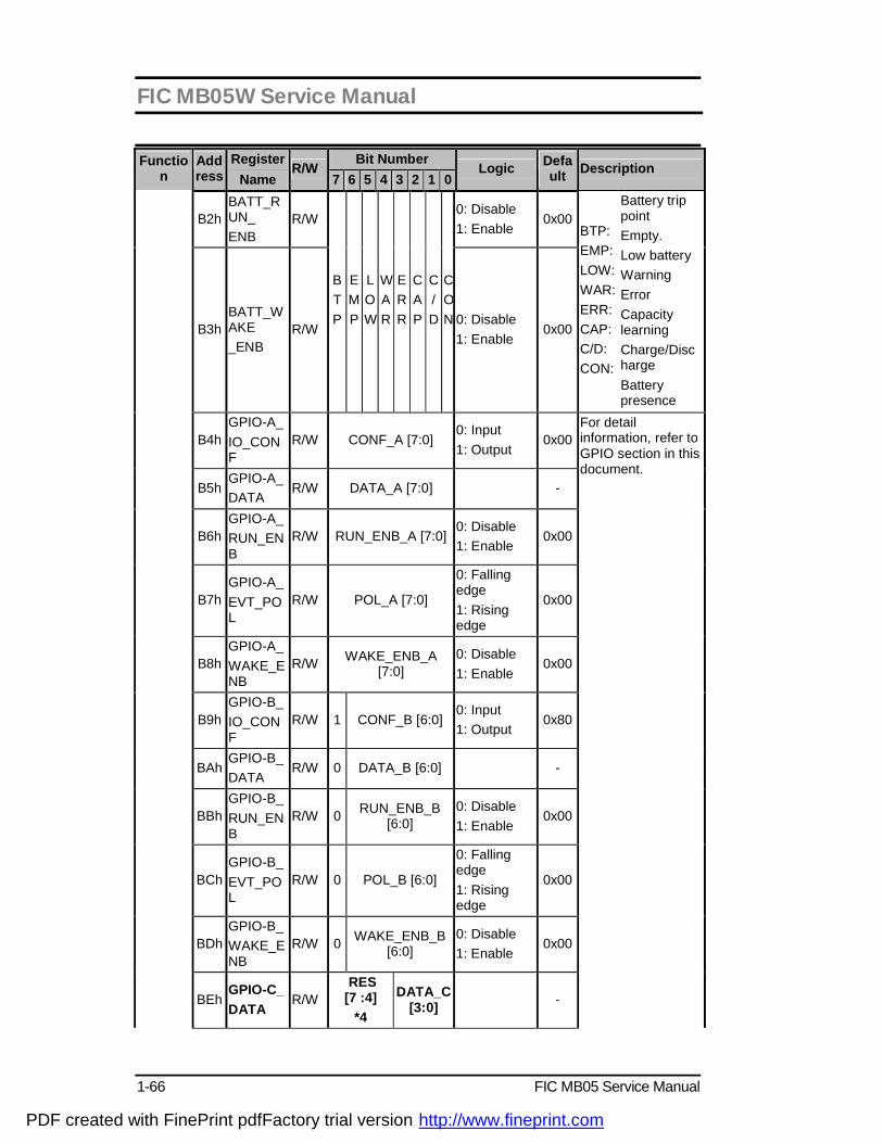
FIC MB05W Service Manual
1-66 FIC MB05 Service Manual
Register Bit Number Function
Address Name
R/W 7 6 5 4 3 2 1 0
Logic Default Description
B2h BATT_RUN_ ENB
R/W 0: Disable 1: Enable
0x00
B3h BATT_WAKE _ENB
R/W
B T P
E M P
L O W
W A R
E R R
C A P
C / D
CON 0: Disable
1: Enable 0x00
BTP: EMP: LOW: WAR: ERR: CAP: C/D: CON:
Battery trip point Empty. Low battery Warning Error Capacity learning Charge/Discharge Battery presence
B4h GPIO-A_ IO_CONF
R/W CONF_A [7:0] 0: Input 1: Output
0x00
B5h GPIO-A_ DATA
R/W DATA_A [7:0] -
B6h GPIO-A_ RUN_ENB
R/W RUN_ENB_A [7:0] 0: Disable 1: Enable
0x00
B7h GPIO-A_ EVT_POL
R/W POL_A [7:0]
0: Falling edge 1: Rising edge
0x00
B8h GPIO-A_ WAKE_ENB
R/W WAKE_ENB_A [7:0]
0: Disable 1: Enable
0x00
B9h GPIO-B_ IO_CONF
R/W 1 CONF_B [6:0] 0: Input 1: Output
0x80
BAh GPIO-B_ DATA
R/W 0 DATA_B [6:0] -
BBh GPIO-B_ RUN_ENB
R/W 0 RUN_ENB_B [6:0]
0: Disable 1: Enable
0x00
BCh GPIO-B_ EVT_POL
R/W 0 POL_B [6:0]
0: Falling edge 1: Rising edge
0x00
BDh GPIO-B_ WAKE_ENB
R/W 0 WAKE_ENB_B [6:0]
0: Disable 1: Enable
0x00
BEh GPIO-C_ DATA
R/W RES [7 :4]
*4
DATA_C [3:0] -
For detail information, refer to GPIO section in this document.
PDF created with FinePrint pdfFactory trial version http://www.fineprint.com

FIC MB05W Service Manual
FIC MB05 Service Manual 1-67
Register Bit Number Function
Address Name
R/W 7 6 5 4 3 2 1 0
Logic Default Description
BFh GPIO-C_ RUN_ENB
R/W 0 0 0 0 0 0
RUN_ ENB_ C
[1:0]
0: Disable 1: Enable
0x00
C0h GPIO-C_ EVT_POL
R/W 0 0 0 0 0 0
POL_C [1:0]
0: Falling edge 1: Rising edge
0x00 Event/ GPIO
Control
C1h GPIO-C_ WAKE_ENB
R/W 0 0 0 0 0 0
WAK E_ ENB
_C [1:0]
0: Disable 1: Enable
0x00
PDF created with FinePrint pdfFactory trial version http://www.fineprint.com

FIC MB05W Service Manual
1-68 FIC MB05 Service Manual
Register Bit Number Function
Address Name
R/W 7 6 5 4 3 2 1 0
Logic Default Description
C2h EVT_CONT R/W
RES
[7:6]
W A K E
S C I
R E S *4
Q _ R U N
W A K E _ O U T
SUS_X
0x00
WAKE SCI Q_RUN WAKE_OUT SUS_X
=0: Wake# output is “Level”. =1: Wake# output is “Pulse”. =0: SCI is always output by event detection and SCI_EVT shows the query data is stored. And next SCI is not output until SCI_EVT is cleared. =1: SCI is output when the command set is not executed and OBF=0. SCI_EVT shows the output SCI is for event notification. =0: Runtime event ststus is reflected to RUN_EVT_STS register. =1: Runtime event status is reflected to Query data.
PDF created with FinePrint pdfFactory trial version http://www.fineprint.com
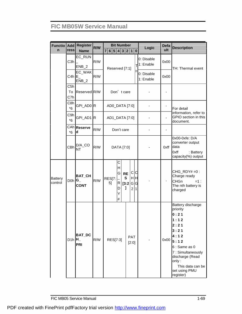
FIC MB05W Service Manual
FIC MB05 Service Manual 1-69
Register Bit Number Function
Address Name
R/W 7 6 5 4 3 2 1 0
Logic Default Description
C3h EC_RUN_ ENB_2
R/W 0: Disable 1: Enable
0x00
C4h EC_WAKE_ ENB_2
R/W
Reserved [7:1] TH
0: Disable 1: Enable
0x00
TH: Thermal event
C5h To
C7h Reserved R/W Don’t care - -
C8h *6
GPI_AD0 R AD0_DATA [7:0] - -
C9h *6
GPI_AD1 R AD1_DATA [7:0] - -
For detail information, refer to GPIO section in this document.
CAh *6
Reserved R/W Don’t care - -
CBh D/A_CONT R/W DATA [7:0] - 0xff
0x00-0xfe: D/A converter output data 0xff : Battery capacity(%) output
D0h BAT_CHG_ CONT
R/W RES[7:5]
C H G_ R D Y #
RES
[3:2]
C H G 2
CHG1
- -
CHG_RDY# =0 : Charge ready CHGn =1 : The nth battery is charged
Battery control
D1h BAT_DCH_ PRI
R/W RES[7:3] PAT [2:0]
- 0x00
Battery discharge priority 0 : 2 1 1 : 1 2 2 : 2 1 3 : 2 1 4 : 1 2 5 : 1 2 6 : Same as 0 7 : Simultaneously discharge (Read only : This data can be set using PMU register)
PDF created with FinePrint pdfFactory trial version http://www.fineprint.com

FIC MB05W Service Manual
1-70 FIC MB05 Service Manual
Register Bit Number Function
Address Name
R/W 7 6 5 4 3 2 1 0
Logic Default Description
D2h BAT_DCH_ CONT
R/W RES[7:2]
D C H G 2
DCHG1
0: Not discharge 1: Discharge
-
The discharge battery can be selected one of the batteries can be discharged.
D3h BAT_WAR_ ABS
R/W DATA[15:0] *1 - 0x0000
Absolute capacity battery Warning detection point 0x0000-0xffff (mWh)
D5h BAT_LOW_ ABS
R/W DATA[15:0] *1 - 0x0000
Absolute capacity battery Low detection point 0x0000-0xffff (mWh)
D7h BAT_WAR_ REL
R/W DATA [7:0] - 0x10
Relative capacity battery Warning detection point 00-C8h (0-100% step 0.5%)
D8h BAT_LOW_ REL
R/W DATA [7:0] - 0x06
Relative capacity battery Low detection point 00-C8h (0-100% step 0.5%)
D9h *3
FULL_DATA R/W DATA [7:0] - 0xbe
Full charge cancel point 00-C8h (0-100% step 0.5%)
Dah CC_CUR_ DATA
R DATA [7:0] - 0x00
Battery charging current setting 0x01-0xff (0.02-5.10A step 0.02A) 0x00 Depends on the battery This register is “read only”, to change the value, use the register in PMU registers area.
PDF created with FinePrint pdfFactory trial version http://www.fineprint.com
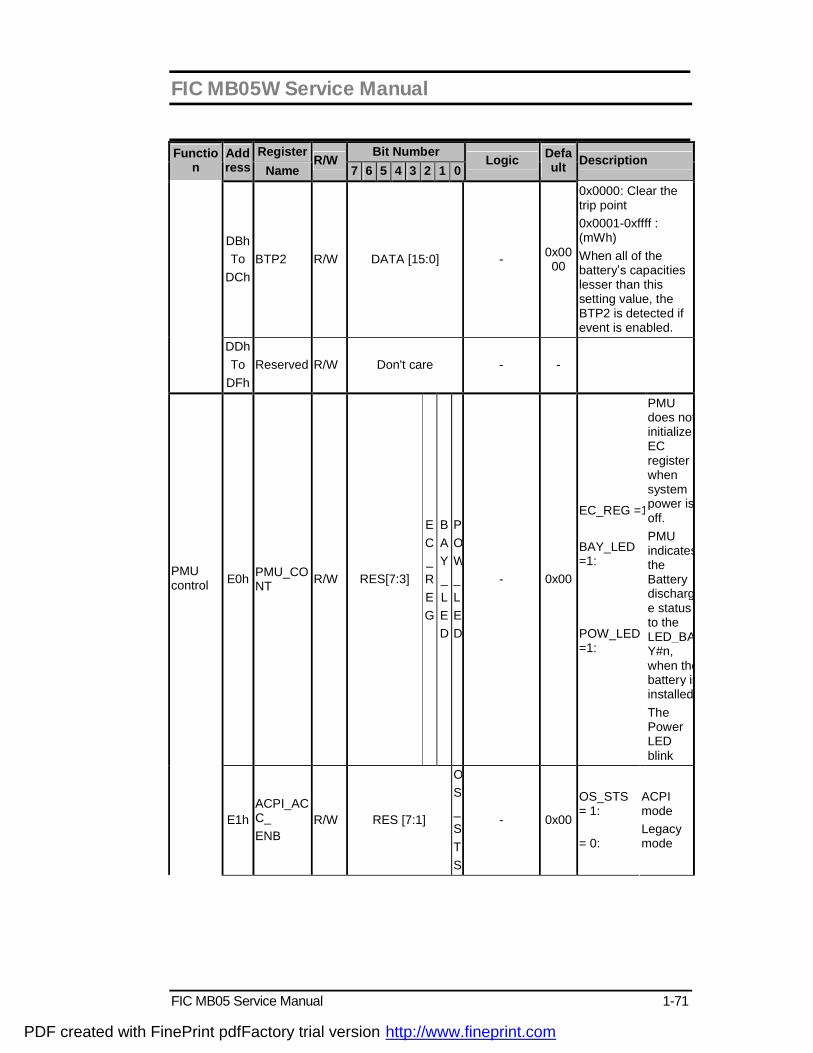
FIC MB05W Service Manual
FIC MB05 Service Manual 1-71
Register Bit Number Function
Address Name
R/W 7 6 5 4 3 2 1 0
Logic Default Description
DBh To
DCh BTP2 R/W DATA [15:0] - 0x00
00
0x0000: Clear the trip point 0x0001-0xffff : (mWh) When all of the battery’s capacities lesser than this setting value, the BTP2 is detected if event is enabled.
DDh To
DFh Reserved R/W Don't care - -
E0h PMU_CONT R/W RES[7:3]
E C _ R E G
B A Y _ L E D
P OW_ L E D
- 0x00
EC_REG =1: BAY_LED =1: POW_LED =1:
PMU does not initialize EC register when system power is off. PMU indicates the Battery discharge status to the LED_BAY#n, when the battery is installed.The Power LED blink
PMU control
E1h ACPI_ACC_ ENB
R/W RES [7:1]
OS _ S T S
- 0x00
OS_STS = 1: = 0:
ACPI mode Legacy mode
PDF created with FinePrint pdfFactory trial version http://www.fineprint.com

FIC MB05W Service Manual
1-72 FIC MB05 Service Manual
Register Bit Number Function
Address Name
R/W 7 6 5 4 3 2 1 0
Logic Default Description
E2h OFF_TIME R/W DATA [7:0] - 0x64
Power switch over ride function timer 01h-FFh (0.1-25.5esc step 0.1sec) 00h : Reserved
E3h
POLLING_ ADDRESS
R/W Slave Address [6:0]
RES
0x00
Address: 0x00-0x7F The polling slave address setting If this address is 00, the Polling is disabled.
E4h HIGH_ ALARM R/W DATA [7:0] Signed value 0x00
If the received data GE this value, the event will be detected.
E5h LOW_ ALARM
R/W DATA [7:0] Signed value 0x00
If the received data LE this value, the event will be detected.
E6h
POLLING_ INTERVAL
R/W DATA [7:0] 0x00
0x00 :Polling disable 0x01 – 0xFF [x 250ms] (250ms to 63.75sec)
E7h POLLING_ DATA
R(/W) DATA [7:0] Signed value 0x00
This register shows data at latest polling.
E8h
HARDWARE_SHUT_DOWN
R/W DATA [7:0] Signed value 0x7D
If the thermal sensor read value GE this value, the PMU automatically off the power.
E9h
POLLING_ COMMAND
R/W DATA [7:0] 0x00 Polling command (data register) address.
EAh RETRY_ COUNT
R/W DATA [7:0] 0x10 0x00 - 0xFF: Retry count value (0-255)
Thermal Sensor Polling
EBh To
EFh Reserved R/W Don't care
PMU control
F0h
BURST_FLG_CLR
R/W DATA [7:0] - -
After writing to the register addressed A8h-AFh, Set the 00h to this register.
PDF created with FinePrint pdfFactory trial version http://www.fineprint.com

FIC MB05W Service Manual
FIC MB05 Service Manual 1-73
Register Bit Number Function
Address Name
R/W 7 6 5 4 3 2 1 0
Logic Default Description
F1h To
FFh Reserved R/W Don't care
3.6.3 Security The user may enter up to 8 standard text characters for a password. The password includes
two levels. The higher priority is the Supervisor Password. The lower priority is the User Password. The Supervisor Password can access all the system resource, while the User Password may not access the floppy disk when it is protected by Supervisor Password. When the security function is enabled, the system will request the user to enter password during the following situation. I. Power On: The system will prompt the user to enter the password before booting the
OS. If the user key in the wrong password for 3 times, then the system will halt. II. Resume: The system will prompt the user to enter password while resuming from STR
or STD mode. If the user keys in the wrong password for 3 times, the system will not resume and should return to Suspend mode again.
III. Entering CMOS Setup: The system will prompt the user to enter the password before entering the CMOS Setup. If the user keys in the wrong password for 3 times, then the system will halt.
3.7 CMOS Setup Utility The Setup utility is used to configure the system. The Setup contains the information regarding the hardware for boot purpose. The changed settings will take effect after the system rebooted. Refer to Chapter 1 on running BIOS Setup Program for more detailed information. 3.8 Definitions of Terms
10Base-T (Ethernet) - A networking standard that supports data transfer rates up to 10Mbps (10 megabits per second).
100Base-T (Fast Ethernet) - A relatively new networking standard that supports data transfer rates up to 100Mbps.
ACPI - Advanced Configuration and Power Management Interface, a power management specification developed by Intel, Microsoft, and Toshiba.
CardBus - The 32-bit version of the PCMCIA PC Card standard. In addition to supporting a wider bus (32 bits instead of 16 bits), CardBus also supports bus mastering and operation speeds up to 33MHz.
Clock Throttling – South bridge function that allows the CPU clock to be stopped and started at a known duty cycle using the STPCLK# pin to enter and exit Stop Grant mode. Clock throttling is used for power saving, thermal management, and reducing the processing speed.
DIMM (SODIMM) - Dual In-line Memory Module, a small circuit board that holds memory chips. A Single In-line Memory Module (SIMM) has a 32-bit path to the memory chips whereas a DIMM has 64-bit path. Because the Pentium processor requires a 64-bit path to memory, you need to install SIMMs two at a time. With DIMMs, you can install one DIMM at a time. SODIMM is Small Outline Dual In-line Memory Module used in notebook computers.
DMI - Desktop Management Interface, an API to enable software to collect information about a computer environment about a computer environment. For example, using DMI a program can determine what hardware and expansion boards are installed on a computer.
GPI - General Purpose Input. GPO - General Purpose Output. Lid Switch - A switch that indicates the notebook LCD Panel has been closed and it can be
PDF created with FinePrint pdfFactory trial version http://www.fineprint.com
FIC MB05W Service Manual
1-74 FIC MB05 Service Manual
turned off. MPEG-2 - Moving Picture Experts Group, a working group of ISO. The term also refers to the
family of digital video compression standards developed by the group. There are two major MPEG standards : MPEG-1 and MPEG-2. The most common implementations of the MPEG-1 standard provide a video resolution 352x240 at 30 frames per second(fps). A newer standard, MPEG-2, offers resolution of 720x480 and 1280x720 at 60 fps, with full CD-quality audio.
North Bridge - The CPU to PCI interface, also contains the memory and cache controllers. South Bridge - The PCI to ISA interface, also contains many legacy devices. SMM - System Management Mode, Mode of operation while an SMI is active. SMI - System Management Interrupt, non-maskable interrupt that causes the system to enter
SMM. SMM functions include power management, USB legacy keyboard control, security, hot keys, and thermal monitoring.
SMB - System Management Bus, that is used for managing smart batteries, reading SDRAM configuration information, and other miscel1aneous system function.
TBD -To Be Discussed. The mentioned specification is not final that should be discussed with related engineers.
Ultra DMA-33 - A protocol developed by Quantum Corporation and Intel that supports burst mode data transfer rates of 33.3 MBps.
USB - A new external bus standard that supports data transfer rates of 12 MBps. A single USB port can be used to connect up to 127 peripheral devices, such as mice, modems, and keyboards. USB also supports Plug-and-Play installation and hot plugging.
PDF created with FinePrint pdfFactory trial version http://www.fineprint.com

FIC MB05W Service Manual
FIC MB05 Service Manual 1-75
4.1 Overview The FIC MB05 notebook consists of several important functions and subsystems including: Notebook size, 2 spindle, IBM PC/AT compatible personal computer with PCI-bus and Multimedia functions, provide full basic function with lowest price and easy of use . The following is a summary of MB05 features:
CPU CPU Type uFCPGA 478pin
Intel Banias 1.3/1.5 GHZ
TDP(Target) 25W Chip Set
Core Logic Intel Montara-GM (North) :CPU(Banias) I/F, LVDS I/F, RGB analog I/F 200/266 DDR MEMORY I/F, Hub-Link I/F, DVOB&DVOC IF….
Intel ICH4-M (South) : PCI I/F, LPC I/F, ATA100 IDE I/F, Hub-Link I/F ,AC97 V2.2 I/F, RTC, 2.0/1.1USB I/F, 10/100M LAN I/F, GPIO, ACPI, APIC….
Memory
Support Memory DDR266/200 SDRAM 128/256/512MB SO-DIMM Memory Slots 2 Slots SO-DIMM (1.25”) Max Memory 1024MB (512MB DIMM X2 )
Video Controller Embedded in Intel Montara-GM.
UMA (using DVMT configuration) High performance & High quality 3D accelerator High performance 2D accelerator Complete TV-OUT/Digital flat panel solution MPEG-2/1 video decoder
Video accelerator
LCD Panel 14.1” XGA Controlled by hot key (8 level) 15.0” XGA TFT/200nit support Controlled by hot key (8 level)
PCMCIA
Controller RICOH R5C554 Single Slot PCI-CARDBUS BRIDGE Built in Smart Card reader(None) ZV-Port Support (None) Ring wakeup support(None)
Power Switch G576 Sound
Controller Integrated in Intel ICH4-M (PCI audio) CODEC Realtek ALC201A AC97 CODEC 2.2 S/PDIF Function Sound Blaster Compatible
S/W Wave Table Buzzer Support (None) Volume SW control.
PDF created with FinePrint pdfFactory trial version http://www.fineprint.com

FIC MB05W Service Manual
1-76 FIC MB05 Service Manual
IEEE 1394(Option) Support two port Controller RICOH R5C554 two IEEE1394 ports BRIDGE Function Compliant with Link Layer Services as defined in 1394 Open
Host Controller Interface specification release 1.0 Compliant with Physical Layer Services as defined in P1394a draft 2.0(Data Rate 100/200/400 Mbps)
Storage USB FDD 3.5” 3 mode(option) IDE bus IDE bus
Bus Mastering Ultra DMA 33/66/100 PIO mode 0,1,2,3,4
Internal HDD 2.5” 9.5 mmH Pack Internal Optical Drive DVD Combo 8x DVD , 8x CDR, CDRW write , 20x CD-ROM 9.5mm type
(KME: UJDA745, Toshiba: SD-R9022) Communication
Internal Modem Ambit (1456VQL19V) (MDC Modem AC97 Interface) (Option) V.90, K56flex RJ11 Jack Wake up on Ring support S1 or S3 Voice Function not support
Internal LAN Realtec 8100BL
10Base-T/100Base-TX RJ-45 jack
I/O Parallel EPP/ECP x1
CRT D-sub 15pin x1 USB 4pin x3 port (Ver:2.0) IEEE 1394 one port H/P Min Jack x1 Mic In Min Jack x1 Modem RJ11 x1 LAN RJ45 x1
Ps2 Ps2 x1 Keyboard
Pitch/Travel 19mm/3mm Language US, Japan, UK
Hot Key Fn+F2: Wireless On/Off
Fn+F3: Display Mode Fn+F4: Sleep Fn+F6: Speaker On/Off Fn+F7: PMU Level(No silk) Fn+F8: Brightness Up (8 leve) Fn+F9: Brightness Down (8 level)
Point Device ALPS : KGDDET 005A Glide Pad AC Adapter LITEON PA-1600-05, DELTA ADP75FB
Input AC 100-240V Output 19V, 60W Peak80W(LITEON), 75W(DELTA) Color Black or White
PDF created with FinePrint pdfFactory trial version http://www.fineprint.com

FIC MB05W Service Manual
FIC MB05 Service Manual 1-77
Battery 1st battery Li-ion (8 cell) SANYO 4400mA(Circle);3600mA(Square) Battery Life 4.5 hours RTC battery x1 Switch
Power SW Push button type (As asserted switch over 4s,system will be powered down by force )
Short Cut Key 3 Short Cut Key (Mail Key and Internet Key) LED Power Status Yes (Need see while LCD is closed) Battery Charge Yes (Need see while LCD is closed) IDE Device Access Yes (HDD & CD-ROM ) Caps Lock Yes Scr Lock Yes Num Lock No Mail arrival No RF Access Yes Security
Kensington Lock Hole x1
PMU PMU08 Compliance
PC2001 compliant ACPI compliant Plug and Play Support Auto Configuration 16bit I/O Address Decoded Selectable I/O Address, IRQ and DMA VESA Support DDC,DPMS
4.2 System Hardware Block Diagram
PDF created with FinePrint pdfFactory trial version http://www.fineprint.com
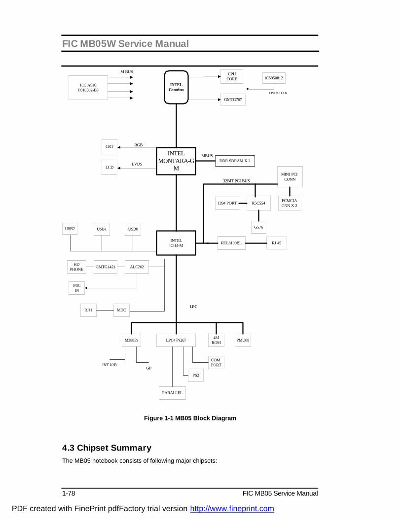
FIC MB05W Service Manual
1-78 FIC MB05 Service Manual
INTELCentrino
INTELICH4-M
LPC47N267
INTELMONTARA-G
M
CPUCORE
GMTG767
ICS950812
CPU PCI CLK
FIC ASICF010502-B0
CRT
LCD
USB1 USB0USB2
DDR SDRAM X 2
MINI PCI CONN
R5C554PCMCIA CNN X 2
G576
1394 PORT
RTL8100BL RJ 45
HDPHONE
ALC202GMTG1421
MDCRJ11
M38859 PMU08
COM PORT
4MROM
PARALLEL
PS2
INT K/BGP
RGB
LVDS
32BIT PCI BUS
LPC
MBUS
M BUS
MICIN
Figure 1-1 MB05 Block Diagram
4.3 Chipset Summary The MB05 notebook consists of following major chipsets:
PDF created with FinePrint pdfFactory trial version http://www.fineprint.com
FIC MB05W Service Manual
FIC MB05 Service Manual 1-79
Controller Chip Vendor Description Processor Intel Mobile Banias North Bridge Intel MontaraGM South Bridge Intel ICH4 Video Controller Intel Embedded in MontaraGM PCMCIA Controller RICOH R5C554 Supper I/O Controller SMSC LPC47N267 Audio Controller Intel South Bridge Integrated Audio Codec Realtek ALC201 Keyboard Controller Misubishi M3885x Power Management NEC PMU08 ROM BIOS SST 49LF004A Clock Generator IMI CY28346 Temperature Sensor NS MAX1617 IEEE 1394 RICOH R5C554 LAN Realtek 8100BL Modem ASKEY MDC AC’97 4.4 System Processor (CPU) The FIC MB05 runs on Intel Banias based on uFCPGA packaging. It supports CPU with up to 1.3/1.5 GHZ clock speed rating. The processor operates in conjunction with the RAM and ROM memory and the system control logic to process software instructions (BIOS, Windows, and Applications).
Intel Pentium M Features The Intel® Pentium® M processor is a high performance, low power mobile processor with several micro-architectural enhancements over existing Intel mobile processors. The following list provides some of the key features on this processor: • Supports Intel® Architecture with Dynamic Execution • High performance, low-power core • On-die, primary 32-kbyte instruction cache and 32-kbyte write-back data cache • On-die, 1-MByte second level cache with Advanced Transfer Cache Architecture • Advanced Branch Prediction and Data Prefetch Logic • Streaming SIMD Extensions 2 (SSE2) • 400-MHz, Source-Synchronous processor system bus • Advanced Power Management features including Enhanced Intel® SpeedStep® technology • Micro-FCPGA and Micro-FCBGA packaging technologies The Intel Pentium M processor is manufactured on Intel ’s advanced 0.13 micron process technology with copper interconnect. The processor maintains support for MMX™ technology and Internet Streaming SIMD instructions and full compatibility with IA-32 software. The high performance core features architectural innovations like Micro-op Fusion and Advanced Stack Management that reduce the number of micro-ops handled by the processor. This results in more efficient scheduling and better performance at lower power. The on-die 32-kB Level 1 instruction and data caches and the 1-MB Level 2 cache with Advanced Transfer Cache Architecture enable significant performance improvement over existing mobile processors. The processor also features a very advanced branch prediction architecture that significantly reduces the number of mispredicted branches. The processor’s Data Prefetch Logic speculatively fetches data to the L2 cache before an L1 cache requests occurs, resulting in reduced bus cycle penalties and improved performance. The Streaming SIMD Extensions 2 (SSE2) enable break-through levels of performance in multimedia applications including 3-D graphics, video decoding/encoding, and speech recognition.The new packed double-precision floating-point instructions enhance performance
PDF created with FinePrint pdfFactory trial version http://www.fineprint.com
FIC MB05W Service Manual
1-80 FIC MB05 Service Manual
for applications that require greater range and precision, including scientific and engineering applications and advanced 3-D geometry techniques, such as ray tracing. The Intel Pentium M processor’s 400-MHz processor system bus utilizes a split-transaction, deferred reply protocol. The 400-MHz processor system bus uses Source-Synchronous Transfer (SST) of address and data to improve performance by transferring data four times per bus clock (4X data transfer rate, as in AGP 4X). Along with the 4X data bus, the address bus can deliver addresses two times per bus clock and is referred to as a “double-clocked” or 2X address bus.Working together, the 4X data bus and 2X address bus provide a data bus bandwidth of up to 3.2 Gbytes/second. The processor system bus uses Advanced Gunning Transceiver Logic (AGTL+)signal technology, a variant of GTL+ signalling technology with low power enhancements. The processor features Enhanced Intel SpeedStep technology, which enables real-time dynamic switching between multiple voltage and frequency points instead of two points supported on previous versions of Intel SpeedStep technology. This results in optimal performance without compromising low power. The processor features the Auto Halt, Stop-Grant, Deep Sleep, and Deeper Sleep low power states. The Intel Pentium M processor utilizes socketable Micro Flip-Chip Pin Grid Array (Micro- FCPGA) and surface mount Micro Flip-Chip Ball Grid Array (Micro-FCBGA) package technology. The Micro-FCPGA package plugs into a 479-hole, surface-mount, Zero Insertion Force (ZIF) socket, which is referred to as the mPGA479M socket. This document includes specifications for the Intel Pentium M processor at Highest Frequency Mode (HFM) core frequencies of 1.30, 1.40, 1.50, and 1.60 GHz, the Low Voltage Intel Pentium M processor at HFM core frequency of 1.10 GHz and the Ultra Low Voltage Intel Pentium M processor at HFM core frequency of 900 MHz.
4.5 System Core Logic
4.5.1 Intel 855GM Chipset GMCH Features Processor/Host Bus Support Ø . Intel® Pentium® M processor Ø . 2x address, 4x data Ø . Supports system bus at 400 MHz Ø . Supports Host bus dynamic bus inversion (DBI) Ø . Supports 64-bit host bus addressing Ø . 12-deep in-order queue Ø . AGTL+ bus driver technology with integrated AGTL+ termination resistors and low
voltage operation (Vtt = 1.05 V) Ø . Supports Enhanced Intel® SpeedStep® technology Ø . Support for DPWR# signal to Intel Pentium M processor for PSB power anagement Memory System Ø . Directly supports one DDR SDRAM channel, 64-bits wide (72-bits with ECC) Ø . Supports 200/266-MHz DDR SDRAM devices with max of two, double-sided SO-
DIMMs (four rows populated) with unbuffered PC1600/PC2100 DDR SDRAM. Ø . Supports 128-Mbit, 256-Mbit, and 512-Mbit technologies providing maximum capacity
of 1 GB with x16 devices and up to 2-GB with high density 512-Mbit technology Ø . All supported devices have four banks Ø . Supports up to 16 simultaneous open pages Ø . Supports page sizes of 2-kB, 4-kB, 8-kB, and 16-kB. Page size is individually selected
for every row Ø . UMA support only
PDF created with FinePrint pdfFactory trial version http://www.fineprint.com
FIC MB05W Service Manual
FIC MB05 Service Manual 1-81
System Interrupts Ø . Supports Intel 8259 and processor system bus interrupt delivery mechanism Ø . Supports interrupts signaled as upstream memory writes from PCI and Hub interface Ø . MSI sent to the CPU through the system bus Ø . IOxAPIC in ICH4-M provides redirection for upstream interrupts to the system bus Video Stream Decoder Ø . Improved hardware motion compensation for MPEG2 Ø . All format decoder (18 ATSC formats) supported Ø . Dynamic Bob and Weave support for video streams Ø . Software DVD at 60 Fields/second and 30 frames/second full screen Ø . Support for standard definition DVD (i.e. NTSC pixel resolution of 720x480, etc.) quality
encoding at low CPU utilization Video Overlay Ø . Single high quality scalable overlay and second Sprite to support second overlay Ø . Multiple overlay functionality provided via arithmetic stretch BLT(Block Transfer) Ø . 5-tap horizontal, 3-tap vertical filtered scaling Ø . Multiple overlay formats Ø . Direct YUV from overlay to TV-out Ø . Independent gamma correction Ø . Independent brightness / contrast/ saturation Ø . Independent tint/hue support Ø . Destination colorkeying Ø . Source chromakeying Multiple hardware color cursor support (32-bit with alpha and legacy 2-bpp mode) Accompanying I2C and DDC channels provided through multiplexed interface Display Ø . Analog display support
‧ 350-MHz integrated 24-bit RAMDAC that can drive a standard progressive scan analog monitor with pixel resolution up to 1600x1200 at 85 Hz and up to 2048x1536 at 75 Hz
Ø . Dual independent pipe support ‧ Concurrent: Different images and native display timings on each display device ‧ Simultaneous: Same images and native display timings on each display device
Ø . DVO (DVOB and DVOC) support ‧ Digital video out ports DVOB and DVOC with 165-MHz dot clock on each 12-bit
interface; two 12-bit channels can be combined to form one dual channel 24-bit interface with an effective dot clock of 330-MHz
‧ The combined DVO B/C ports as well as individual DVO B/C ports can drive a variety of DVO devices (TV-Out Encoders, TMDS and LVDS transmitters, etc.) with pixel resolution up to 1600x1200 at 85 Hz and up to 2048x1536 at 72 Hz.
‧ Compliant with DVI Specification 1.0 Ø R
Ø . Dedicated LFP (local flat panel) LVDS interface ‧ Single- or dual-channel LVDS panel support up to UXGA panel resolution with
frequency range from 25 MHz to 112 MHz (single channel/dual channel) ‧ Supports data format of 18 bpp ‧ SSC support of 0.5%, 1.0%, and 2.5% center and down spread with external SSC
clock LCD panel power sequencing compliant with SPWG timing specification
PDF created with FinePrint pdfFactory trial version http://www.fineprint.com
FIC MB05W Service Manual
1-82 FIC MB05 Service Manual
Compliant with ANSI/TIA/EIA –644-1995 spec Integrated PWM interface for LCD backlight inverter control Bi-linear panel fitting
. Tri-view support through LFP interface, DVO B/C port, and CRT Internal Graphics Features Ø . Up to 64 MB of dynamic video memory allocation Ø . Display image rotation Ø . Graphics core frequency Ø . Display core frequency at 133 MHz or 200 MHz Ø . Render core frequency at 100 MHz,133 MHz, 200 MHz Ø . 2D graphics engine
n Optimized 128-bit BLT engine n Ten programmable and predefined monochrome patterns n Alpha Stretch BLT (via 3D pipeline) n Anti-aliased lines n Hardware-based BLT Clipping and Scissoring n 32-bit Alpha Blended cursor n Programmable 64 x 64 3-color Transparent cursor n Color Space Conversion n Three Operand Raster BLTs n 8-bit, 16-bit, and 32-bit color n ROP support n DIB translation and Linear/Tile addressing
Ø . 3D graphics engine n 3D setup and render engine n Zone rendering n High quality performance texture engine n Viewpoint transform and perspective divide n Triangle lists, strips and fans support n Indexed vertex and flexible vertex formats n Pixel accurate fast scissoring and clipping operation n Backface culling support n DirectX* and OpenGL* pixelization rules n Anti-Aliased lines support n Sprite points support n Provides the highest sustained fill rate performance in 32-bit color and 24-bit W
mode n High quality performance texture engine n 266-MegaTexel/s peak performance n Per pixel perspective corrected texture mapping n Single pass texture compositing (multi-textures) n Enhanced texture blending functions n Twelve level of detail MIP map sizes from 1x1 to 2k x 2k n Numerous texture formats including 32-bit RGBA n Alpha and Luminance maps n Texture chromakeying n Bilinear, trilinear, and anisotropic MIP map filtering n Cubic environment reflection mapping n Dot product bump-mapping n Embossed bump-mapping n DXTn texture decompression n FX1 texture compression n 3D graphics rasterization enhancements n One Pixel per clock n Flat and Gouraud shading
PDF created with FinePrint pdfFactory trial version http://www.fineprint.com
FIC MB05W Service Manual
FIC MB05 Service Manual 1-83
n Color alpha blending for transparency n Vertex and programmable pixel fog and atmospheric effects n Color specular lighting n Z Bias support n Dithering n Line and full-scene anti-aliasing n 16 and 24-bit Z buffering n 16 and 24-bit W buffering n 8-bit Stencil buffering n Double and triple render buffer support n 16 and 32-bit color n Destination alpha n Vertex cache n Optimal 3D resolution supported n Fast Clear support n ROP support
Hub Interface to ICH4-M . 266 -MB/s point-to-point Hub Interface to ICH4-M . 66-MHz base clock Power Management Ø . SMRAM space remapping to A0000h (128-kB) Ø . Supports extended SMRAM space above 256-MB, additional 1-MB TSEG from top of
memory, cacheable (cacheability controlled by CPU) Ø . APM Rev 1.2 compliant power management Ø . Supports Suspend to System Memory (S3), Suspend to Disk (S4) and Soft Off (S5) Ø . ACPI 1.0b, 2.0 support Ø . Enhanced Intel SpeedStep technology support Package . 732-pin Micro-FCBGA (37.5 x 37.5 mm) 4.5.2 Intel ICH4 Features
The ICH4 provides extensive I/O support. Functions and capabilities include:
•PCI Local Bus Specification, Revision 2.2-compliant with support for 33-MHz PCI operations.
•PCI slots (supports up to 6 Req/Gnt pairs)
•ACPI Power Management Logic Support
•Enhanced DMA Controller, Interrupt Controller, and Timer Functions
•Integrated IDE controller supports Ultra ATA100/66/33
•USB host interface with support for 6 USB ports; 3 UHCI host controllers; 1 EHCI high-speed USB 2.0 Host Controller
•Integrated LAN Controller
•System Management Bus (SMBus) Specification, Version 2.0 with additional support for I2C devices
•Supports Audio Codec ’97, Revision 2.3 specification (a.k.a., AC ’97 Component
PDF created with FinePrint pdfFactory trial version http://www.fineprint.com
FIC MB05W Service Manual
1-84 FIC MB05 Service Manual
Specification, Revision 2.3). Link for Audio and Telephony codecs (up to 7 channels)
•Low Pin Count (LPC) interface
•Firmware Hub (FWH) interface support
•Alert On LAN* (AOL) and Alert On LAN 2* (AOL2)
Hub Architecture
As I/O speeds increase, the demand placed on the PCI bus by the I/O bridge has become significant. With AC ’97, USB 2.0, and Ultra ATA/100, coupled with the existing USB, I/O requirements could impact PCI bus performance. The chipset’s hub interface architecture ensures that the I/O subsystem; both PCI and the integrated I/O features (IDE, AC ‘97, USB, etc.), receive adequate bandwidth. By placing the I/O bridge on the hub interface (instead of PCI), the hub architecture ensures that both the I/O functions integrated into the ICH4 and the PCI peripherals obtain the bandwidth necessary for peak performance.
PCI Interface
The ICH4 PCI interface provides a 33-MHz, Rev. 2.2 compliant implementation. All PCI signals are 5-V tolerant, except PME#. The ICH4 integrates a PCI arbiter that supports up to six external PCI bus masters in addition to the internal ICH4 requests.
IDE Interface (Bus Master Capability and Synchronous DMA Mode)
The fast IDE interface supports up to four IDE devices providing an interface for IDE hard disks and ATAPI devices. Each IDE device can have independent timings. The IDE interface supports PIO IDE transfers up to 16 Mbytes/sec and Ultra ATA transfers up 100 Mbytes/sec. It does not consume any ISA DMA resources. The IDE interface integrates 16x32-bit buffers for optimal transfers.
The ICH4’s IDE system contains two independent IDE signal channels. They can be electrically isolated independently. They can be configured to the standard primary and secondary channels (four devices). There are integrated series resistors on the data and control lines (see Section 5.15, “IDE Controller (D31:F1)” on page 5-175 for details).
Low Pin Count (LPC) Interface
The ICH4 implements an LPC Interface as described in the LPC 1.0 specification. The Low Pin Count (LPC) Bridge function of the ICH4 resides in PCI Device 31:Function 0. In addition to the LPC bridge interface function, D31:F0 contains other functional units including DMA, Interrupt Controllers, Timers, Power Management, System Management, GPIO, and RTC.
Note that in the current chipset platform, the Super I/O (SIO) component has migrated to the Low Pin Count (LPC) interface. Migration to the LPC interface allows for lower cost Super I/O designs.
Compatibility Modules (DMA Controller, Timer/Counters, Interrupt Controller)
The DMA controller incorporates the logic of two 82C37 DMA controllers, with seven independently programmable channels. Channels 0–3 are hardwired to 8-bit, count-by-byte
PDF created with FinePrint pdfFactory trial version http://www.fineprint.com
FIC MB05W Service Manual
FIC MB05 Service Manual 1-85
transfers, and channels 5–7 are hardwired to 16-bit, count-by-word transfers. Any two of the seven DMA channels can be programmed to support fast Type-F transfers.
The ICH4 supports two types of DMA (LPC and PC/PCI). DMA via LPC is similar to ISA DMA. LPC DMA and PC/PCI DMA use the ICH4’s DMA controller. The PC/PCI protocol allows PCI-based peripherals to initiate DMA cycles by encoding requests and grants via two PC/PCI REQ#/GNT# pairs.
LPC DMA is handled through the use of the LDRQ# lines from peripherals and special encodings on LAD[3:0] from the host. Single, Demand, Verify, and Increment modes are supported on the LPC interface. Channels 0–3 are 8 bit channels. Channels 5–7 are 16 bit channels. Channel 4 is reserved as a generic bus master request.
The timer/counter block contains three counters that are equivalent in function to those found in one 82C54 programmable interval timer. These three counters are combined to provide the system timer function, and speaker tone. The 14.31818-MHz oscillator input provides the clock source for these three counters.
The ICH4 provides an ISA-Compatible Programmable Interrupt Controller (PIC) that incorporates the functionality of two 82C59 interrupt controllers. The two interrupt controllers are cascaded so that 14 external and two internal interrupts are possible. In addition, the ICH4 supports a serial interrupt scheme.
All of the registers in these modules can be read and restored. This is required to save and restore system state after power has been removed and restored to the platform.
Advanced Programmable Interrupt Controller (APIC)
In addition to the standard ISA compatible Programmable Interrupt Controller (PIC) described in the previous section, the ICH4 incorporates the Advanced Programmable Interrupt Controller
Universal Serial Bus (USB) Controller
The ICH4 contains an Enhanced Host Controller Interface (EHCI) compliant host ontroller that supports USB high-speed signaling. High-speed USB 2.0 allows data transfers up to 480 Mb/s which is 40 times faster than full-speed USB. The ICH4 also contains three Universal Host Controller Interface (UHCI) controllers that support USB full-speed and low-speed signaling.
The ICH4 supports 6 USB 2.0 ports. All six ports are high-speed, full-speed, and low-speed capable. ICH4’s port-routing logic determines whether a USB port is controlled by one of the UHCI controllers or by the EHCI controller. See Section 5.16, “USB UHCI Controllers (D29:F0, F1 and F2) and Section 5.17, “USB EHCI Controller (D29:F7) for details.
LAN Controller
The ICH4’s integrated LAN Controller includes a 32-bit PCI controller that provides enhanced scatter-gather bus mastering capabilities and enables the LAN Controller to perform high speed data transfers over the PCI bus. Its bus master capabilities enable the component to process high-level commands and perform multiple operations; this lowers processor utilization by off-loading communication tasks from the processor. Two large transmit and
PDF created with FinePrint pdfFactory trial version http://www.fineprint.com

FIC MB05W Service Manual
1-86 FIC MB05 Service Manual
receive FIFOs of 3 kB each help prevent data underruns and overruns while waiting for bus accesses. This enables the integrated LAN Controller to transmit data with minimum interframe spacing (IFS).
The LAN Controller can operate in either full duplex or half duplex mode. In full duplex mode the LAN Controller adheres with the IEEE 802.3x Flow Control specification. Half duplex performance is enhanced by a proprietary collision reduction mechanism. See Section 5.2, “LAN Controller (B1:D8:F0)” on page 5-78 for details.
RTC
The ICH4 contains a Motorola* MC146818A-compatible real-time clock with 256 bytes of battery-backed RAM. The real-time clock performs two key functions: keeping track of the time of day and storing system data, even when the system is powered down. The RTC operates on a 32.768 KHz crystal and a separate 3-V lithium battery that provides up to seven years of protection.
The RTC also supports two lockable memory ranges. By setting bits in the configuration space, two 8-byte ranges can be locked to read and write accesses. This prevents unauthorized reading of passwords or other system security information.
The RTC also supports a date alarm that allows for scheduling a wake up event up to 30 days in advance, rather than just 24 hours in advance. 4.6 Clock Frequency Generator The notebook utilizes the IMI CY28346 chip to supply the system clock needed to run the computer. The following are the available clock frequencies: System clock:
Clock generator IMI CY28346 support: - 66/100 MHz for Pentium III Mobile CPU - 30/33 MHz for PCI device bus clock use - 48 MHz for PIIX4M - 14.318 MHz for PIIX4M refresh use
• 14.318 MHz XTAL for Clock Generator use • 32.768 KHz XTAL for RTC real time clock • 8.0 MHz XTAL for K/B controller use • 14.318 MHz OSC for sound blaster use
4.7 Cache Memory The primary (L1) and secondary (L2) level cache are integrated on the CPU. By incorporating the cache on-die (meaning it is combined with the CPU into one component), Intel eliminates the need for separate components. The 512KB on-die L2 cache provides three (3X) times faster processor access, resulting in significant improvements in performance. Likewise, an integrated cache means a reduction of connections resulting in increased reliability. 4.8 System Memory The memory subsystem, implemented on the motherboard, includes System and Video memory. The Intel 855GM System Controller chip provides primary control for the system memory.
PDF created with FinePrint pdfFactory trial version http://www.fineprint.com

FIC MB05W Service Manual
FIC MB05 Service Manual 1-87
4.8.1 System Memory The notebook offers two 64-bit SODIMM (Small Outline Dual Inline Memory Module) sockets for main memory configuration. The memory sockets accept any standard 144-pin SODIMM modules at 128MB, 256MB,512MB and 1GMB sizes. Memory modules are DDR 200/266 SDRAM type.
4.8.2 Video Memory The video memory of the notebook is using share system memory with 8/16/32MB UMA video memory that can support display resolutions of up to 1024 x 768 at 32-bit 16M color (TFT LCD). 4.9 System BIOS The notebook utilizes the Phoenix BIOS 4.0 Release 6.0 (Basic I/O System) that contains both the main system BIOS and the VGA BIOS with Shadow BIOS capability. It utilizes Flash EPROM BIOS that allows instant erasing and programming without replacing the EPROM chip. The BIOS is stored in a 32-pin PLCC package FLASH ROM SST 49LF040A with 4Mbit size and is mounted into the motherboard. While posting the system, the Shadow RAM will be enabled and the ROM will be disabled. 4.10 Video Subsystem The video subsystem, embedded inside the North Bridge chip and the LCD panel, controls the display output to both the LCD Panel screen and to the external VGA port. 4.10.1 Video Chip Controller Features summary of the Intel 852GM Video Chip Controller:
Video Stream Decoder . Improved HW Motion Compensation for MPEG2 . All format decoder (18 ATSC formats) supported . Dynamic Bob and Weave support for Video Streams . Software DVD at 60 fields/second and 30 frames/second full screen . Support for standard definition DVD (i.e. NTSC pixel resolution of 720x480, etc.) quality
encoding at low CPU utilization Video Overlay . Single high quality scalable Overlay and second Sprite to support second Overlay . Multiple Overlay functionality provided via Arithmetic Stretch Blt . 5-tap horizontal, 3-tap vertical filtered scaling . Multiple Overlay formats . Direct YUV from Overlay to TV-out . Independent Gamma Correction . Independent Brightness / Contrast/ Saturation . Independent Tint/Hue support . Destination Colorkeying . Source Chromakeying Multiple hardware color cursor support (32-bit with alpha and legacy 2-bpp mode) Accompanying I2C and DDC channels provided through multiplexed interface Display . Analog Display Support . 350-MHz integrated 24-bit RAMDAC that can drive a standard progressive scan analog
PDF created with FinePrint pdfFactory trial version http://www.fineprint.com

FIC MB05W Service Manual
1-88 FIC MB05 Service Manual
monitor with pixel resolution up to 1600x1200 at 85-Hz and up to 1920x1440 at 60 Hz . Dual independent pipe support ‧ Concurrent: Different images and native display timings on each display device ‧ Simultaneous: Same images and native display timings on each display device . DVO (DVOC) support ‧ Digital video out port DVOC with 165-MHz dot clock on 12-bit double pumped interface ‧ Variety of DVO devices supported ‧ Compliant with DVI Specification 1.0, thereby providing support for a display resolution up to 1400x1050 @ 75-Hz, up to 1600x1200 at 60-Hz, or up to 1920x1200 @ 60 Hz . Dedicated LFP (local flat panel) LVDS interface ‧ Single or dual channel LVDS panel support up to SXGA+(1400x1050 @ 60 Hz) panel resolution with frequency range from 25-MHz to 112-MHz (single channel/dual channel) ‧ SSC support of 0.5%, 1.0%, and 2.5% center and down spread with external SSC clock ‧ Supports data format of 18-bpp ‧ LCD panel power sequencing compliant with SPWG timing specification ‧ Compliant with ANSI/TIA/EIA –644-1995 spec ‧ Integrated PWM interface for LCD backlight inverter control ‧ Bi-linear Panel fitting . Tri-view support through LFP interface, DVO C port, and CRT Internal Graphics Features . Up to 64 MB of Dynamic Video Memory Allocation . Display Image Rotation . Core Frequency ‧ Display Core frequency of 133-MHz ‧ Render Core frequency of 133-MHz . 2D Graphics Engine ‧ Optimized 128-bit BLT engine ‧ Ten programmable and predefined monochrome patterns ‧ Alpha Stretch Blt (via 3D pipeline) ‧ Anti-aliased lines ‧ Hardware-based BLT Clipping and Scissoring ‧ 32-bit Alpha Blended cursor ‧ Programmable 64 x 64 3-color Transparent cursor ‧ Color Space Conversion ‧ 3 Operand Raster BLTs ‧ 8-bit, 16-bit, and 32-bit color ‧ ROP support ‧ DIB translation and Linear/Tile addressing . 3D Graphics Engine ‧ 3D Setup and Render Engine ‧ Viewpoint Transform and Perspective Divide ‧ Triangle Lists, Strips and Fans support ‧ Indexed Vertex and Flexible Vertex formats ‧ Pixel accurate Fast Scissoring and Clipping operation ‧ Backface Culling support ‧ DirectX* and OGL Pixelization rules ‧ Anti-Aliased Lines support ‧ Sprite Points support ‧ Provides the highest sustained fill rate performance in 32-bit color and 24-bit W mode ‧ High quality performance Texture Engine ‧ 266-MegaTexel/s peak performance
PDF created with FinePrint pdfFactory trial version http://www.fineprint.com

FIC MB05W Service Manual
FIC MB05 Service Manual 1-89
‧ Per Pixel Perspective Corrected Texture Mapping ‧ Single Pass Texture Compositing (Multi-Textures) at rate ‧ Enhanced Texture Blending functions ‧ Twelve Level of Detail MIP Map Sizes from 1x1 to 2Kx2K ‧ Numerous Texture formats including 32-bit RGBA ‧ Alpha and Luminance Maps ‧ Texture Chromakeying ‧ Bilinear, Trilinear, and Anisotropic MIP - Mapped Filtering ‧ Cubic Environment Reflection Mapping ‧ Embossed Bump-Mapping ‧ DXTn Texture Decompression ‧ FX1 Texture Compression ‧ 3D Graphics Rasterization enhancements ‧ One Pixel per clock ‧ Flat and Gouraud Shading ‧ Color Alpha Blending for Transparency ‧ Vertex and Programmable Pixel Fog and Atmospheric effects ‧ Color Specular Lighting ‧ Z Bias support ‧ Dithering ‧ Line and Full-Scene Anti-Aliasing ‧ 16 and 24-bit Z Buffering ‧ 16 and 24-bit W Buffering ‧ 8-bit Stencil Buffering ‧ Double and Triple Render Buffer support ‧ 16 and 32-bit color ‧ Destination Alpha ‧ Vertex Cache ‧ Maximum 3D resolution of 1600x1200 at 85- Hz (contact your Intel Field Representative
for detailed display information, i.e. pixel depths, etc.) ‧ Optimal 3D resolution supported ‧ Fast Clear support ‧ ROP support
4.10.2 Video Clock Intel 852GM North Bridge provides input to generate VGA internal slate machine, MCLK, and DCLK. Also provides 32.768 KHz O/P for video RAM refresh. 4.11 PCMCIA Controller The PCMCIA controller of the notebook is implemented on the motherboard using the RICOH R5C554 CardBus Controller. The MB05 notebook only supports single PCMCIA slot for PCI-Cardbus Bridge.
CARDBUS CONTROLLERS The R5C554 is an ACPI and PC98/99 logo certified high performance, single slot PC Card controller with a synchronous 32-bit bus master/target PCI interface. This PC Card to PCI bridge host controller is compliant with the 2000 PC Card Standard. This standard incorporates the new 32-bit CardBus while retaining the 16-bit PC Card specification as defined by PCMCIA release 2.1. CardBus is intended to support "temporal" add-in functions on PC Cards, such as Memory cards, Network interfaces, FAX/Modems and other wireless
PDF created with FinePrint pdfFactory trial version http://www.fineprint.com
FIC MB05W Service Manual
1-90 FIC MB05 Service Manual
communication cards, etc. The high performance and capability of the CardBus interface will enable the new development of many new functions and applications. The R5C554 CardBus controller is compliant with the latest ACPI-PCI Bus Power Management interface Specification. It supports all four power states and the PME# function for maximum power savings and ACPI compliance. Additional compliance to On Now Power Management includes D3 cold state support, paving the way for low sleep state power consumption and minimized resume times. To allow host software to reduce power consumption further, the R5C554 provides a power-down mode in which internal clock distribution and the PC Card socket clocks are stopped. An advanced CMOS process is also used to minimize system power consumption. The R5C554 single PCMCIA socket supports the 3.3V/5V 8/16-bit PC Card R2 cards or 32-bit CardBus R3 cards. The R2 card support is compatible with the Intel 82365SL PCIC controller, and the R3 card support is fully compliant with the 2000 PC Card Standard CardBus specification. The R5C554 is an additional buffer chip for the PC Card socket interface. In addition, the R5C554 supports dynamic PC Card hot insertion and removal, with auto configuration capabilities. The R5C554 is fully complains with the 33Mhz PCI Bus specification, v2.2. It supports a master device with internal CardBus direct data transfer. The R5C554 implements FIFO data buffer architecture between the PCI bus and CardBus socket interface to enhance data transfers to CardBus Devices. The bi-directional FIFO buffer permits the R5C554 to accept data from a target bus (PCI or CardBus interface) while simultaneously transferring data. This architecture not only speeds up data transfers but also prevents system deadlocks. The R5C554 is a PCMCIA R2/CardBus controller, providing the most advanced design flexibility for PC Cards that interface with advanced notebook designs.
R5C554 FEATURES – Slot Solution
• Supports only one PCMCIA 2.1 and JEIDA 4.2 R2 cards or 2 CardBus cards
• ACPI-PCI Bus Power Management Interface Specification Rev 1.1 Compliant
• Supports OnNow LAN wakeup, OnNow Ring Indicate, PCI CLKRUN#, PME#, and CardBus CCLKRUN#
• Compliant with the 33Mhz PCI Specification V2.2, 2000 PC Card Standard 7.1 for R5C554
• Yenta™ PCI to PCMCIA CardBus Bridge register compatible
• ExCA (Exchangeable Card Architecture) compatible registers map-able in memory and I/O space
• Intel™ 82365SL PCIC Register Compatible
• Supports PCMCIA_ATA Specification
• Supports 5V/3.3V PC and 3.3V Cardbus cards
• Supports two PC Card or CardBus slots with hot insertion and removal
• Supports multiple FIFOs for PCI/CardBus data transfer
• Supports Direct Memory Access for PC/PCI and PCI/Way on PC Card socket
PDF created with FinePrint pdfFactory trial version http://www.fineprint.com

FIC MB05W Service Manual
FIC MB05 Service Manual 1-91
• Programmable interrupt protocol: PCI, PCI+ISA, PCI/Way, or PC/PCI interrupt signaling modes
• Win'98 IRQ and PC-98/99 compliant
• Parallel or Serial interface for socket power control devices including Micrel and TI
• Integrated PC 98/99 -Subsystem Vendor ID support, with auto lock bit
• LED Activity Pins
• R5C554 supports D3cold state PME# wakeup; 3.3Vaux Power; and Zoomed video buffer enable pins
• R5C554: "Built-in" live video, high throughput, multimedia ZV ports support without additional buffers; 3V card protection during host system suspend with Auto Card VS# resensing; dedicated ZV output port to LCD controller
SmartCardBus™ combines a Smart Card reader and CardBus controller in a single IC. In addition to meeting PC Card standards, SmartCardBus is compliant to Microsoft PC/SC, ISO 7816-1, -2, -3 electrical specifications, standard protocols including T = 0, T = 1, and synchronous and asynchronous formats. SmartCardBus lowers the cost of ownership of e-commerce and corporate security Smart Card applications. 4.12 Audio Subsystem The audio subsystem is integrated inside the South Bridge chip on the motherboard. Refer to the System Core Logic section of this chapter. An internal two-way mini speaker and microphone provide the notebook with mobile sound generation and recording capabilities. In addition, a set of 3.5mm bayonet socket (1/8” minijack) connectors allow for external microphone, line inputs, and headphone outputs. 4.13 Keyboard and Pointing Device The Keyboard Subsystem of the notebook is implemented on the Motherboard and Keyboard Assembly using the Mitsubishi M38859 keyboard controller chip and the Mitsubishi M38859 keyboard controller firmware. This chip controls the internal built-in keyboard, the built-in touchpad pointing device, as well as the external PS/2 keyboard and mouse port. The keyboard controller allows simultaneous use of both the internal and external keyboard and PS/2 mouse. The MB05 membrane keyboard is an 86-key IBM 101-key enhanced compatible keyboard with standard characters and 12 function keys including an embedded numeric keypad. See Chapter 1 for more information. The pointing device subsystem consists of the built-in Synaptics touch pad pointing device module on the system top cover assembly and a pre-programmed Mitsubishi M38859 micro-controller that interfaces the mouse device to the Motherboard. The touch pad module is connected to battery board through a 6-pin FPC cable. An external PS/2 port also supports the use of an external PS/2 compatible mouse where the system automatically detects on system power up and runs both internal and external mouse simultaneously.
PDF created with FinePrint pdfFactory trial version http://www.fineprint.com

FIC MB05W Service Manual
1-92 FIC MB05 Service Manual
The Synaptic touch pad, a pointing device for personal computers, detects the position of a finger over a touch-sensitive area. To move the cursor, the user lightly slides a finger over the smooth sensor area. To ‘click’, the user gently taps on the surface. The ultra-thin module is the thinnest PCB based touchpad available today. It is a capacitive sensor - the finger is detected by measuring its effect on an array of capacitive lines integrated into the PC board. The pad senses both the finger’s position and its contact area (X, Y, and Z). The area of contact is a measure of applied pressure. One side of the module PC board is the sensor surface; electronic components are mounted on the other side. The sensitive area is protected by a layer of smooth and durable mylar. The Synaptic touch pad communicates with the host via a standard PS/2 mouse or trackball interface. It is fully compatible with the standard Microsoft mouse driver. The module connector includes the PS/2 signal pins, power supply pins and two connections for external button switches. The Synaptic touch pad includes a special “edge-motion” feature that allows the user to extend a drag operation when the finger reaches the edge of the sensor pad. The cursor continues to coast in the indicated direction when the finger is held against the edge. 4.14 IDE Drives Subsystem The disk drives subsystem, implemented on the Motherboard and on the associated internal hard disk drive assembly and device bay, provides disk storage for all system sof tware and user files. The notebook is equipped with high capacity hard disk drive using Enhanced IDE controller with LBA (Logical Block Addressing) and Ultra DMA mode support. The ICH4 controller chip provides the Primary IDE controller for the internal hard disk, and the Secondary Master for the CD-ROM. The notebook uses the 24X-speed IDE CD-ROM Drive and 8X-speed DVD-ROM. The CD-ROM drive supports CD-DA transfer over ATAPI function that the host system can read CD audio data. The drive also supports Photo-CD Multi-session disc compatibility and Multimedia PC-3 specification compatibility. The notebook also could use the 8X+ speed IDE DVD-ROM Drive that reads DVD digital data stored on DVD-ROM at 8 times faster rotational speed. 4.15 Power Subsystem The Power Subsystem consists of the following major sections:
4.15.1 AC Power Adapter The computer is equipped with a 60W Peak 80W universal AC power adapter that converts AC voltage (100 to 240VAC, 50 to 60Hz) into DC voltage used to operate the notebook and charge the batteries. 4.15.2 Internal Battery Pack The computer utilizes Lithium-Ion (Li-Ion) that provides DC power for the notebook and real time clock battery on the motherboard when the AC Adapter is not connected to the computer.
PDF created with FinePrint pdfFactory trial version http://www.fineprint.com
FIC MB05W Service Manual
FIC MB05 Service Manual 1-93
The normal charging time for the battery is around 3.5 hours when computer is turn off while it should take around 8 hours when the computer is running. Running time of battery is around 4.5 hours.
4.15.3 DC-DC Module of Motherboard The DC-DC module receives approximately 12VDC from the battery pack and uses this input voltage to generate multiple regulated output voltages to provide power for all internal notebook board assemblies.
4.15.4 LCD Inverter Board Assembly The LCD Inverter Board Assembly is located in the LCD Panel Assembly. It converts the +12VDC input directly from the Battery Pack into a high voltage AC output used to light the CCFT (Cold-Cathode Fluorescent Tube). 4.16 Micro-P Subsystem (PMU-08) The micro controller NEC PMU08 acts as a supplement for the power management control. It supports many functions via the SMBus interface. The system communicates with the PMU08 via the SMBus interface. The SMBus host should be first initialized before starting the transaction. The following is the procedure for system communication with PMU08:
1. Enable SMBus interface by writing 01h to SmbHstCfg register. 2. Get SMBus I/O port base address by reading from SmbBA register. 3. Clear SMBus status by writing 1Eh to SmbHstSts register. 4. Write the PMU07 slave address to SmbHstAdd register.
− Send command to PMU08 -- Slave address is 04h. − Read data from PMU08 -- Slave address is 05h.
5. Write the desired command to SmbHstCmd register. 6. Write the desired parameters to SmbHstDat0 (High byte) and SmbHstDat1 (Low byte)
registers if the system wants to send command to PMU08. 7. Wait for SMBus interrupt occurred by monitoring SmbHstSts register INTR bit. 8. Get the desired data by reading from SmbHstDat0 (High byte) and SmbHstDat1 (Low
byte) registers if the system wants to read data from PMU08. Features Summary of the Micro-P:
• 5 channels 8-bit analog to digital converter • Timer0: 8-bit tuner/counter with 8-bit prescaler • Timer1: 16-bit timer/counter. TMR1 can be incremented during sleep via external
crystal/clock • Timer2: 8-bit timer/counter with 8-bit period register, prescaler and postscaler • Capture, Compare, PWM module • Synchronous Serial port (SSP) with SPI and I
2C
• Universal Synchronous Asynchronous Receiver Transmitter (USART/SCI) • Brown-out detection circuitry for Brown-out Reset (BOR) • 2K bytes program memory • 128 bytes data memory • 22 I/O pin • 8 interrupt sources
PDF created with FinePrint pdfFactory trial version http://www.fineprint.com

FIC MB05W Service Manual
1-94 FIC MB05 Service Manual
5.1 Introduction This section contains preventive and corrective maintenance procedures for the MB05 notebook. The first part of the section describes the computer cleaning procedures and preferred handling procedures for sensitive components (e.g. disk drives, LCD, CPU, batteries). The second part of the chapter identifies all field replaceable parts with the remainder explaining the removal and replacement procedures for the field replaceable parts. 5.2 Preventive Maintenance Preventive maintenance is limited to cleaning the plastic case, the keyboard, and the display screen and cleaning the floppy drive heads as required.
5.2.1 Cleaning the Computer When it is necessary to clean the plastic case and keyboard, use a soft lint-free cloth, slightly dampened with a mild detergent solution, or use the contents of any commercially available computer cleaning kit.
i Never use alcohol, petroleum-based solvents, or harsh detergents to clean the notebook. Also, do not spray any liquids directly on the computer case, keyboard, or screen. If the liquid-crystal display (LCD) screen has become smeared or dusty, clean the screen by first applying a mild glass cleaner to a soft, clean, lint-free cloth, and gently wipe the glass. Never apply liquids directly on the screen surface. Moreover, do not use paper towels to clean the display screen. Paper can scratch the display screen matte.
5.2.2 Maintaining the LCD Quality When it comes to screen problems, heat plays a big part. After a good working session, the typical routine is to shut the machine and close the cover. But the display surface - no matter what type it is - and the components inside the computer radiates heat; when you close the cover, you trap the heat against the screen. Leave the computer's cover open for about ten minutes while the heat disperses. Make this a habit.
PDF created with FinePrint pdfFactory trial version http://www.fineprint.com

FIC MB05W Service Manual
FIC MB05 Service Manual 1-95
5.2.3 Maintaining the Hard Disk Drive The hard disk drive is one of the most common parts that always gets problem. Here is some preventive maintenance that you can do when handling the hard disk. • Always back up the data files from the hard disk. • Run a virus detecting program for possible virus infected area on the hard disk. • Use SCANDISK to correct any errors found in the directory and File Allocation Table
(FAT). This will also free up space from any unused sectors. • Never turn the computer off when the hard disk is being accessed. • Never move or raise the computer while the hard disk is being accessed, most especially
don't jar the hard disk as this may cause a hard disk crash. • Use hard disk system tools like Disk Defragmenter under Windows. This reorganizes
your hard disk by eliminating fragmentation and improves the hard disk access time.
5.2.4 Handling the Computer Battery Packs The battery packs furnished with the computer require reasonable care and handling to ensure efficient operation and maximum life. Periodically inspect the battery terminals and the batteries for evidence of corrosion and oxide build-up. To ensure that the battery packs endure normal life cycle, always observe the following precautions when handling the battery packs: • Do not drop the battery packs or subject them to excessive shock and vibration. • Do not expose the battery packs to direct sunlight, moisture, or chemical compounds. • Do not disassemble the battery packs. • Do not use the battery packs to power other devices. • Do not short the battery leads or connect the battery with reversed polarity. • Never attempt to charge the battery packs in any way other than as described in this
manual and the User’s Manual. • Always charge the battery packs as soon as possible after a low battery indication.
PDF created with FinePrint pdfFactory trial version http://www.fineprint.com
FIC MB05W Service Manual
1-96 FIC MB05 Service Manual
5.3 Required Tools and Equipment To troubleshoot and repair PC systems properly, you need a few basic tools: • Tweezers • Small flat-blade screwdriver • Small Cross screwdriver • Regular size Cross screwdriver • Small Hex-bolt screwdriver •
i All boards, options, and peripherals contain components that are sensitive to static electricity. When handling any of these items, use wrist or ankle grounding straps and grounded working mats. When moving or storing items, use the anti-static bags supplied with the items.
5.4 Notebook Field-Replaceable Parts and Assemblies The notebook contains two major assemblies: The Cover Display LCD Assembly and the System Unit Assembly.
5.4.1 Cover-Display LCD assembly The Cover-Display LCD Assembly includes the following major Field Replaceable Units/parts (FRUs): • LCD Face and Back Panel Cover
These parts are used to cover the whole LCD Panel assembly, which includes the LCD Display Module, the LCD FPC cables, and inverter board.
• LCD Display Module
“14” LCD (Liquid Crystal Display) screen is used for output display. This part is assembled together with LCD Power Inverter Board, and LCD cables contained inside the whole LCD Panel. Handle this part with care against static electricity and accidents that can break the LCD.
• LCD Power Inverter Board
This part or PCB (Printed Circuit Board) is used to provide high voltage to the CCFT (Cold Cathode Fluorescent Tube) of the notebook’s LCD backlighting. It is connected to the right side of the LCD display screen and attached to the back panel by a screw. Exercise safety electrical precautions in handling and servicing this part. The circuit board also includes the function for displaying the power status and battery charge LED indicators.
• LCD FPC Cable
The LCD FPC cable is used to convert output signals from the motherboard in driving the LCD display screen. The cable is connected to the back of the LCD Panel.
5.4.2 System Unit Assembly The System Unit Assembly comprise of several assemblies of which can be divided into two major sub-assemblies. • The System Top Unit Assembly. • The System Base Unit Assembly.
PDF created with FinePrint pdfFactory trial version http://www.fineprint.com

FIC MB05W Service Manual
FIC MB05 Service Manual 1-97
The following System Top Unit Assembly includes the following major Field Replaceable Units/parts (FRUs): • Glidepad Touch Pad Module Assembly
The touch pad (glide pad) pointing device module is assembled at the underside of the top cover with the sensor pad exposed on the top. The assembly comprises of the glide pad board, the glide pad converter board, the select buttons bracket casing, the insulator sheet, the glide pad FPC cable, and the glidepad wire cable. The glide pad board is assembled just underneath the select button assembly. It provides a FPC cable connector for the mother board.
• Keyboard Panel Assembly
The keyboard is assembled on top of the system unit and connected to the main board’s keyboard FPC type connector. The keyboard is also secured on the system’s top unit casing. There are no screws attached to the keyboard.
• Heat Plate and Fan Exhaust Unit
The Fan Exhaust unit is assembled on the upper-right side of the system unit. It comprises of a heat plate and one fan. There are seven screws securing the heat plate to the CPU module inserted on the motherboard. The exhaust fan is secured beside the heat plate.
• Keyboard Cover Assembly The keyboard cover is a thin bracket for holding the keyboard as well as covering the base unit. It is also includes the power button, easy buttons, and status LED cover moldings.
The following System Base Unit Assembly includes the following major Field Replaceable Units/parts (FRUs):
• Battery Pack
This is one of more easily replaceable parts. The battery pack is found on the right side on the base unit and can be easily removed by pressing the latch underneath the unit and pulling the battery on its handle. The battery pack is replaced as a whole and must not be opened for repair.
• Hard Disk Drive Module
The Hard Disk Drive is attached on the lower-left side of the system base unit located just below the keyboard. The HDD is secured by only one screw. The HDD module is a 2.5 -inch hard disk drive with a maximum height of 9.5mm. The hard drive module assembly is attached to the motherboard through the HDD connector.
• CD-ROM / DVD-ROM Drive Assembly The CD-ROM / DVD-ROM / Drive Assembly is attached on the right side of the base unit and is lock with one latch.
• CPU
The Pentium socket is found on the top right part of the motherboard. You will need a flat screwdriver and CPU tooling for removing or installing the CPU. Refer to Chapter 2 on how to install and upgrade the CPU.
• Speaker Assembly The internal speakers of the notebook are assembled into front side of the system. They are secured into a slot and speaker cable connector is attached into the main board.
PDF created with FinePrint pdfFactory trial version http://www.fineprint.com

FIC MB05W Service Manual
1-98 FIC MB05 Service Manual
• Motherboard Assembly
The Motherboard assembly is the most important part of the notebook. It contains the entire major chipsets including the core logic, PCMCIA, memory, and BIOS to operate the whole computer. It also includes the sockets, connectors and ports completing the functionality.
• Internal Modem / LAN / Combo Module Assembly
If the computer includes an internal modem, LAN
• System Base Unit Case The System Base Unit Case is where the Motherboard is placed. It includes openings for the battery, FDD, CD-ROM and PCMCIA equipment.
5.5 Parts Removal and Replacement Procedures This section contains the field service-level removal/ replacement procedures for the notebook of MB05 model. The notebook is designed for optimum modularity in order to make field replacement and maintenance easy and efficient.
5.5.1 Removing the Battery Pack The procedure for removing and replacing the battery pack is as follows: To remove the battery pack, slide the latch to left side and hold it, then take out the battery pack with your finger.
Figure 5-1 Remove the battery pack
5.5.2 Removing the Keyboard The internal keyboard is located above the system top unit and is fitted in without screws on the top unit case. Follow the steps below on how to remove the keyboard: 12. Turn off the system and remove both AC adapter and the battery pack from the notebook
unit. 13. Remove keyboard cover by gently bending it and sliding it towards in front of you.
PDF created with FinePrint pdfFactory trial version http://www.fineprint.com
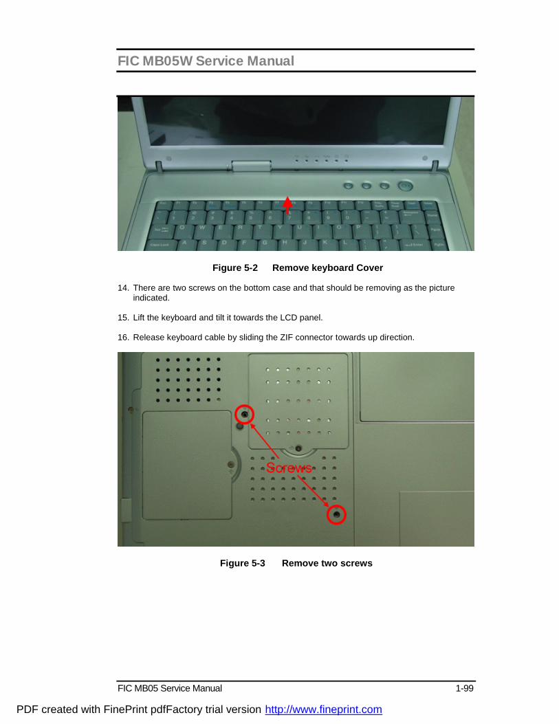
FIC MB05W Service Manual
FIC MB05 Service Manual 1-99
Figure 5-2 Remove keyboard Cover 14. There are two screws on the bottom case and that should be removing as the picture
indicated. 15. Lift the keyboard and tilt it towards the LCD panel. 16. Release keyboard cable by sliding the ZIF connector towards up direction.
Figure 5-3 Remove two screws
PDF created with FinePrint pdfFactory trial version http://www.fineprint.com
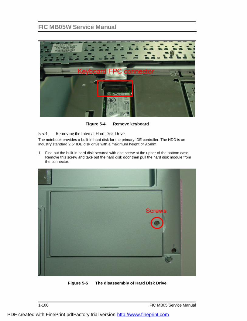
FIC MB05W Service Manual
1-100 FIC MB05 Service Manual
Figure 5-4 Remove keyboard 5.5.3 Removing the Internal Hard Disk Drive The notebook provides a built-in hard disk for the primary IDE controller. The HDD is an industry standard 2.5” IDE disk drive with a maximum height of 9.5mm. 1. Find out the built-in hard disk secured with one screw at the upper of the bottom case.
Remove this screw and take out the hard disk door then pull the hard disk module from the connector.
Figure 5-5 The disassembly of Hard Disk Drive
PDF created with FinePrint pdfFactory trial version http://www.fineprint.com

FIC MB05W Service Manual
FIC MB05 Service Manual 1-101
2. Remove four screws of frame HDD bracket plate.
Figure 5-6 Screws Locations of the frame HDD bracket plate 5.5.4 Removing the heat sink plate The procedure for removing the heat sink plate is as follows: 1. Removing the plate, there are three screws as the picture shown.
Figure 5-7 Removing the heat sink plate
PDF created with FinePrint pdfFactory trial version http://www.fineprint.com
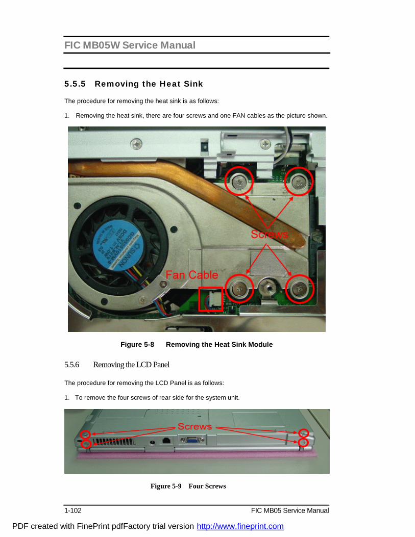
FIC MB05W Service Manual
1-102 FIC MB05 Service Manual
5.5.5 Removing the Heat Sink The procedure for removing the heat sink is as follows: 1. Removing the heat sink, there are four screws and one FAN cables as the picture shown.
Figure 5-8 Removing the Heat Sink Module 5.5.6 Removing the LCD Panel The procedure for removing the LCD Panel is as follows:
1. To remove the four screws of rear side for the system unit.
Figure 5-9 Four Screws
PDF created with FinePrint pdfFactory trial version http://www.fineprint.com
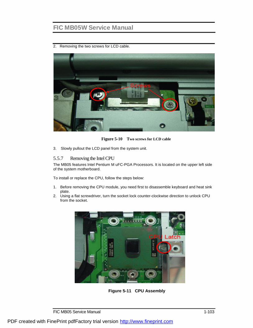
FIC MB05W Service Manual
FIC MB05 Service Manual 1-103
2. Removing the two screws for LCD cable.
Figure 5-10 Two screws for LCD cable
3. Slowly pullout the LCD panel from the system unit.
5.5.7 Removing the Intel CPU The MB05 features Intel Pentium M uFC-PGA Processors. It is located on the upper left side of the system motherboard. To install or replace the CPU, follow the steps below: 1. Before removing the CPU module, you need first to disassemble keyboard and heat sink
plate. 2. Using a flat screwdriver, turn the socket lock counter-clockwise direction to unlock CPU
from the socket.
Figure 5-11 CPU Assembly
PDF created with FinePrint pdfFactory trial version http://www.fineprint.com
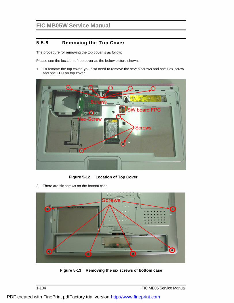
FIC MB05W Service Manual
1-104 FIC MB05 Service Manual
5.5.8 Removing the Top Cover The procedure for removing the top cover is as follow: Please see the location of top cover as the below picture shown. 1. To remove the top cover, you also need to remove the seven screws and one Hex-screw
and one FPC on top cover.
Figure 5-12 Location of Top Cover 2. There are six screws on the bottom case
Figure 5-13 Removing the six screws of bottom case
PDF created with FinePrint pdfFactory trial version http://www.fineprint.com
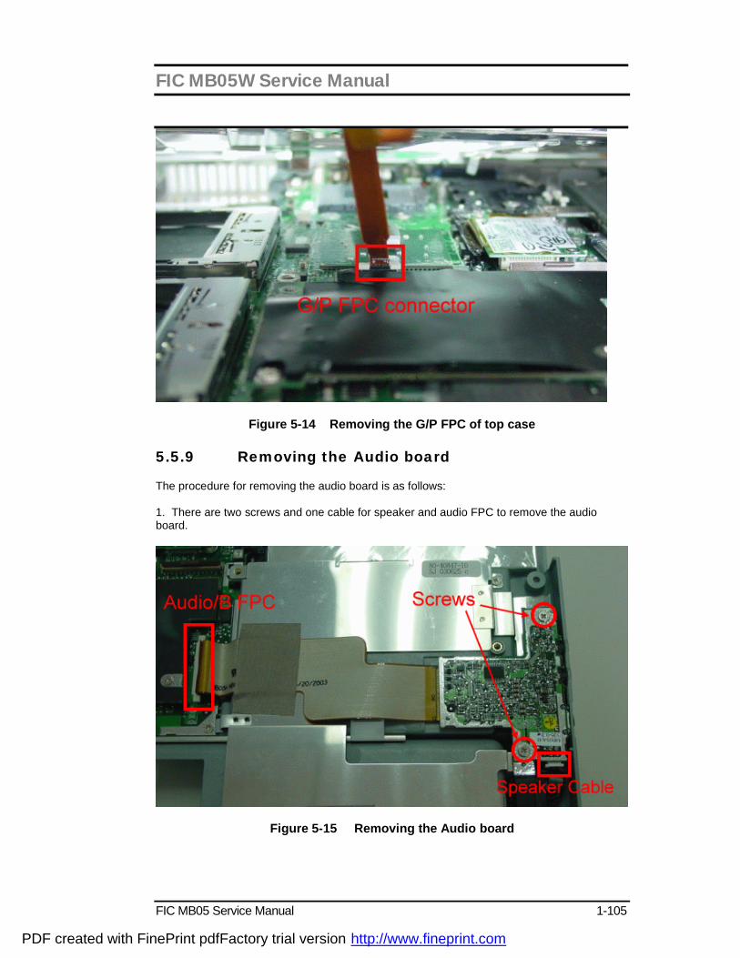
FIC MB05W Service Manual
FIC MB05 Service Manual 1-105
Figure 5-14 Removing the G/P FPC of top case
5.5.9 Removing the Audio board The procedure for removing the audio board is as follows: 1. There are two screws and one cable for speaker and audio FPC to remove the audio board.
Figure 5-15 Removing the Audio board
PDF created with FinePrint pdfFactory trial version http://www.fineprint.com
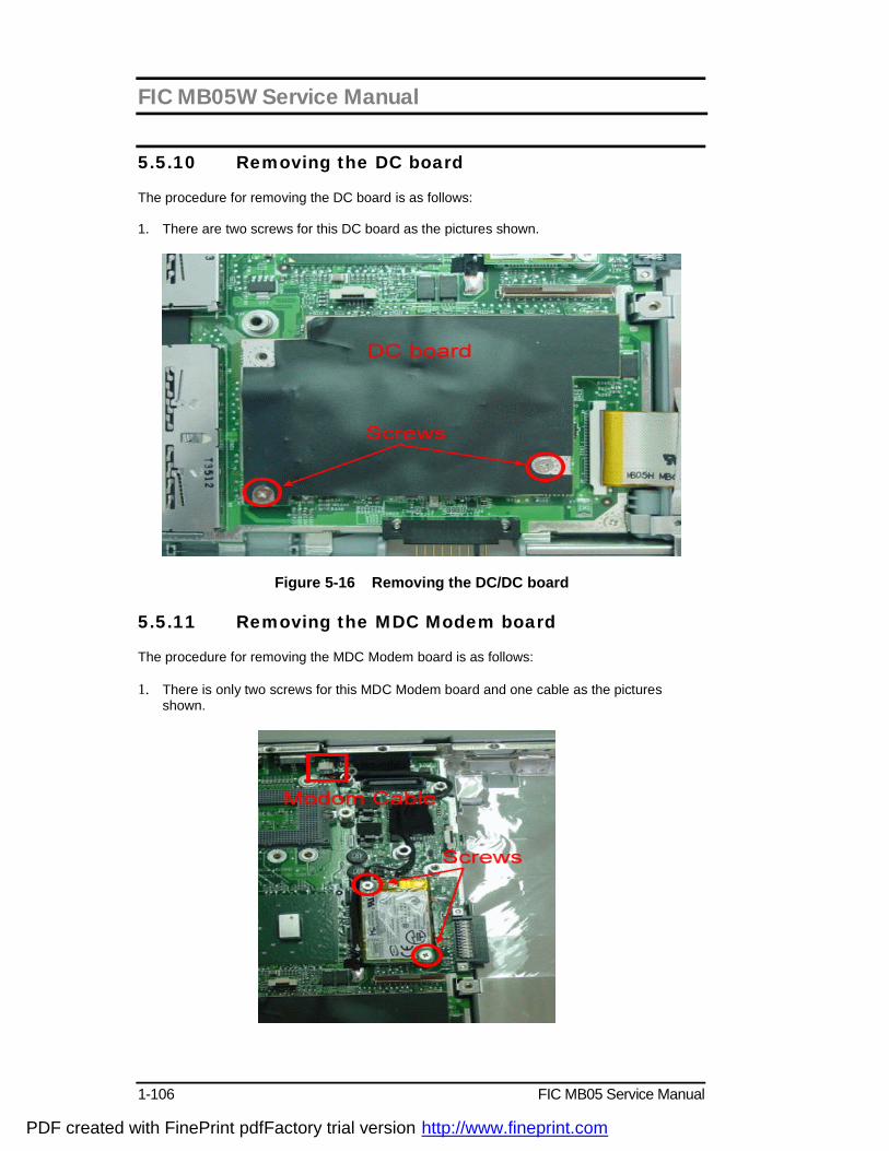
FIC MB05W Service Manual
1-106 FIC MB05 Service Manual
5.5.10 Removing the DC board The procedure for removing the DC board is as follows: 1. There are two screws for this DC board as the pictures shown.
Figure 5-16 Removing the DC/DC board
5.5.11 Removing the MDC Modem board The procedure for removing the MDC Modem board is as follows: 1. There is only two screws for this MDC Modem board and one cable as the pictures
shown.
PDF created with FinePrint pdfFactory trial version http://www.fineprint.com
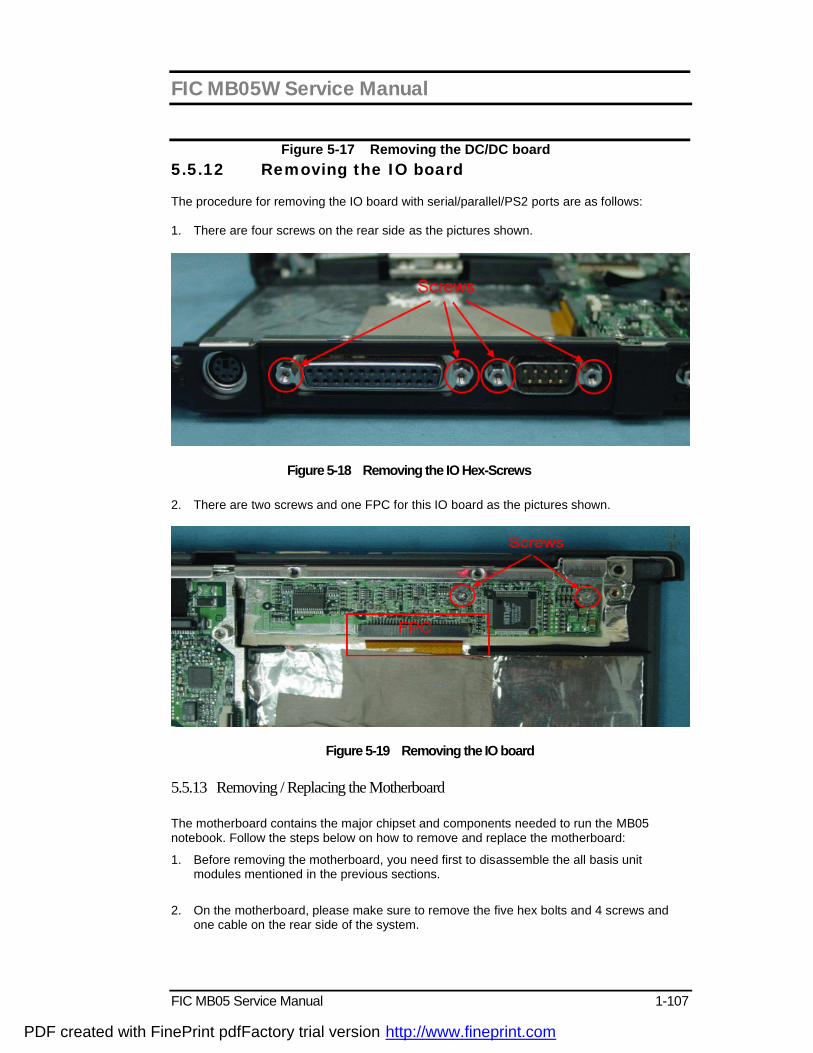
FIC MB05W Service Manual
FIC MB05 Service Manual 1-107
Figure 5-17 Removing the DC/DC board 5.5.12 Removing the IO board The procedure for removing the IO board with serial/parallel/PS2 ports are as follows: 1. There are four screws on the rear side as the pictures shown.
Figure 5-18 Removing the IO Hex-Screws 2. There are two screws and one FPC for this IO board as the pictures shown.
Figure 5-19 Removing the IO board 5.5.13 Removing / Replacing the Motherboard The motherboard contains the major chipset and components needed to run the MB05 notebook. Follow the steps below on how to remove and replace the motherboard:
1. Before removing the motherboard, you need first to disassemble the all basis unit modules mentioned in the previous sections.
2. On the motherboard, please make sure to remove the five hex bolts and 4 screws and
one cable on the rear side of the system.
PDF created with FinePrint pdfFactory trial version http://www.fineprint.com

FIC MB05W Service Manual
1-108 FIC MB05 Service Manual
Figure 5-20 Motherboard Screws Location
3. You will see two Hex-screws as the picture shown.
Figure 5-21 Removing Hex-Screws
4. When all screws and bolts are removing, the mother board and FPC should lift up together gently from the casing of base unit..
PDF created with FinePrint pdfFactory trial version http://www.fineprint.com

FIC MB05W Service Manual
FIC MB05 Service Manual 1-109
This appendix provides the technical specification of the MB05 notebook: A.1 System Specification Category Specification Stepping
CPU Intel Mobile Centrino Processor FSB Speed 400MHz
Core Logic
MONTARA-GM (North Bridge) CPU Interface Integrated 3D/2D Graphic Engine. AGP Bus Controller DDR DRAM Controller HUB Interface ICH4-M (South Bridge ) Hub Interface Technology interconnecting INTEL NB and SB. Dual IDE Master/Slave Controller ,Integrated DMA Controller Universal Serial Bus Host Controller Integrated LAN Controller(Not use) Integrated Audio Controller with AC97 Interface Advanced Programmable Interrupt Controller Integrated PCI to LPC Bridge Integrated RTC compatible MC146818A with
256bytes of battery backed RAM Integrated Audio Controller with AC97 Interface PCI Bus Interface (PCI 2.2 compliant) Note: See INTEL spec for Detail.
Cache Memory L1 Cache (Centrino Processor internal): 64KB 8-way cache association provides
L2 Cache (Centrino Processor internal): 1024KB Advanced Transfer Cache,8 way association 8-way set associative, 32-byte line size, 1 line per sector
System Memory Base Memory: 1 SO-DIMM Slot (1.25”) Size: 128/256/512MB Type: DDR SDRAM, 2.5V Data Path: 64Bit Frequency: 266MHz Refresh: CBR Refresh Expansion Memory: 1 SO-DIMM Slot (1.25”) Size: 128/256/512MB Type: DDR SDRAM, 2.5V Data Path: 64Bit Frequency : 266MHz Refresh: CBR Refresh
PDF created with FinePrint pdfFactory trial version http://www.fineprint.com
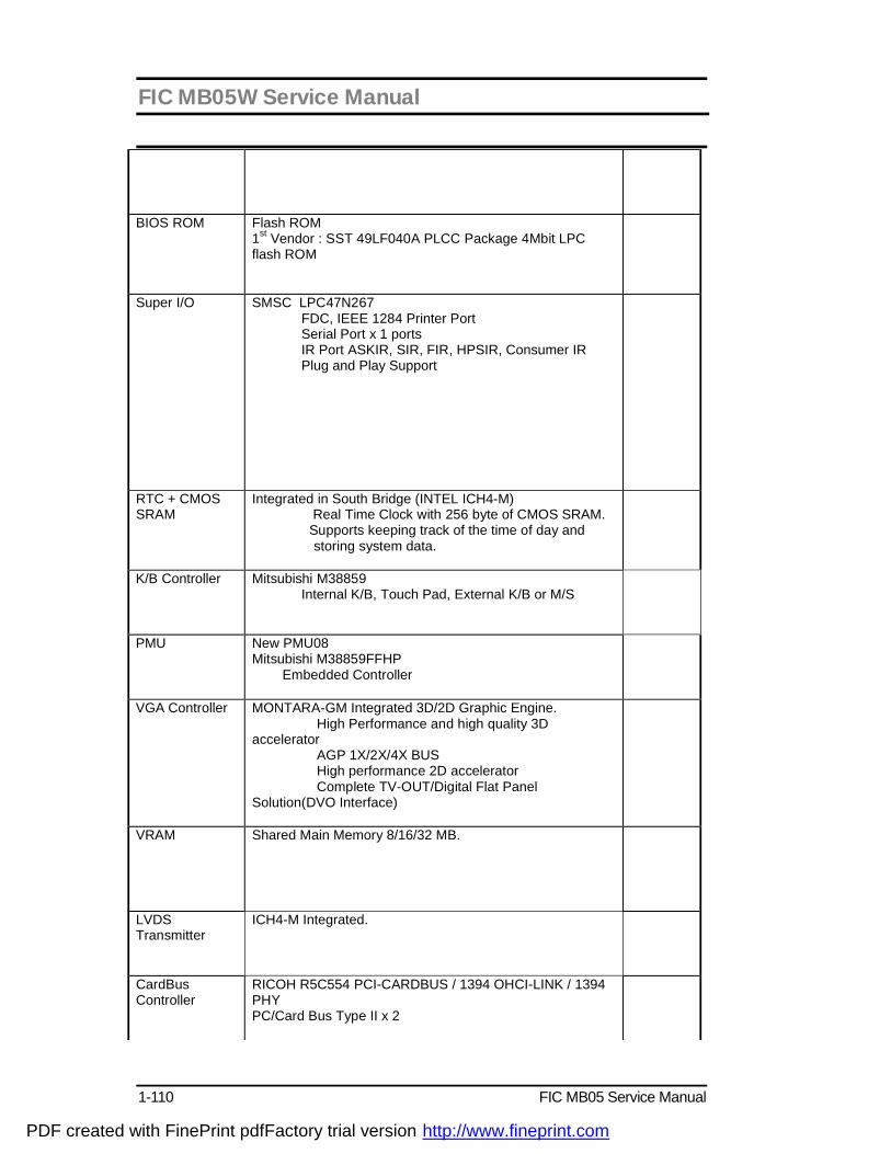
FIC MB05W Service Manual
1-110 FIC MB05 Service Manual
BIOS ROM Flash ROM 1st Vendor : SST 49LF040A PLCC Package 4Mbit LPC flash ROM
Super I/O
SMSC LPC47N267 FDC, IEEE 1284 Printer Port Serial Port x 1 ports IR Port ASKIR, SIR, FIR, HPSIR, Consumer IR Plug and Play Support
RTC + CMOS SRAM
Integrated in South Bridge (INTEL ICH4-M) Real Time Clock with 256 byte of CMOS SRAM. Supports keeping track of the time of day and
storing system data.
K/B Controller Mitsubishi M38859 Internal K/B, Touch Pad, External K/B or M/S
PMU New PMU08 Mitsubishi M38859FFHP Embedded Controller
VGA Controller MONTARA-GM Integrated 3D/2D Graphic Engine. High Performance and high quality 3D accelerator AGP 1X/2X/4X BUS High performance 2D accelerator Complete TV-OUT/Digital Flat Panel Solution(DVO Interface)
VRAM Shared Main Memory 8/16/32 MB.
LVDS Transmitter
ICH4-M Integrated.
CardBus Controller
RICOH R5C554 PCI-CARDBUS / 1394 OHCI-LINK / 1394 PHY PC/Card Bus Type II x 2
PDF created with FinePrint pdfFactory trial version http://www.fineprint.com
FIC MB05W Service Manual
FIC MB05 Service Manual 1-111
Sound
AC’97 CODEC Realtek ALC202 AC’97 Revision 2.2 Compliant
Modem MDC modem support V.90, K56flex, ITU-T V.34, V.32, RJ11 Jack TIA/EIA 602, V.42 ITU-T V.17, V.29, V.27ter, V.21 Ch2 TIA/EIA 578 Class1 FAX Wake up on Ring
On board LAN Realtek 8100BL Support LAN boot( no used) Support for auto-negotiation (10BASE-T and 100BASE-TX) Wake up On LAN( S1~S5).
802.11a+b 802.11 b
Support by Mini-pci.
1394 RICOH R5C554 PCI-CARDBUS / 1394 OHCI-LINK / 1394 PHY
USB (ICH4-M)
Integrated in South Bridge (INTEL ICH4-M) Three Independent UHCI USB 1.1 Host Controllers and One EHCI USB 2.0 Host Controller, support up to six port. Legacy Keyboard/Mouse support. Supports only one Debug port at port 1(first port), it is at USB 2.0 transfer rate..
A.2 Display Specification 15” TFT LCD (HANNSTAR) LCD Model HSD150PX16-A LCD Type 15” TFT Display Pixels H1024 x V768 pixels Pixel Arrangement RGB vertical stripe Display colors 262K Colors Module Size 298.5(W) x 227.5(H) x 5.8(D) [mm] Weight Approx. 500g Contrast Ratio 200:1 (typ.) Power Supply 3.3V Response Time 30ms (max) Operating Temperature 0 to 50 degrees Celsius
PDF created with FinePrint pdfFactory trial version http://www.fineprint.com

FIC MB05W Service Manual
1-112 FIC MB05 Service Manual
Storage Temperature -20 to 60 degrees Celsius
15” TFT LCD (LG) LCD Model LP150X05-C2 LCD Type 15” TFT Display Pixels H1024 x V768 pixels Pixel Arrangement RGB vertical stripe Display colors 262K Colors Module Size 298.5(W) x 227.5(H) x 5.8(D) [mm] Weight Approx. 500g Contrast Ratio 200:1 (typ.) Power Supply 3.3V Response Time 30ms (max) Operating Temperature 0 to 50 degrees Celsius Storage Temperature -20 to 60 degrees Celsius
15” TFT LCD (AU) LCD Model B150XG01-2 LCD Type 15” TFT Display Pixels H1024 x V768 pixels Pixel Arrangement RGB vertical stripe Display colors 262K Colors Module Size 298.5(W) x 227.5(H) x 5.8(D) [mm] Weight Approx. 500g Contrast Ratio 200:1 (typ.) Power Supply 3.3V Response Time 30ms (max) Operating Temperature 0 to 50 degrees Celsius Storage Temperature -20 to 60 degrees Celsius
14.1” TFT LCD (SAMSUNG) LCD Model LTN141XB-L02 LCD Type 14.1” TFT Display Pixels H1024 x V768 pixels Pixel Arrangement RGB vertical stripe Display colors 262K Colors Module Size 298.5(W) x 227.5(H) x 5.8(D) [mm] Weight Approx. 500g Contrast Ratio 200:1 (typ.) Power Supply 3.3V Response Time 30ms (max) Operating Temperature 0 to 50 degrees Celsius
PDF created with FinePrint pdfFactory trial version http://www.fineprint.com

FIC MB05W Service Manual
FIC MB05 Service Manual 1-113
Storage Temperature -20 to 60 degrees Celsius
A.5 DVD/ RW Combo Drive Specification Drive Manufacturer QSI SBW242 Physical Dimension 128.0 x 12.7 x 129 [mm] ( W * H * D ) Weight 250g +/- 10g Loading Manual tray loading Ejection Manual eject using the eject button
Auto eject using the eject command on software Host Interface Enhanced IDE (ATAPI) Average Access Time 150ms Typ. Data Transfer Rate (burst) 16.7 MByte/s (PIO Mode 4)
16.7 MByte/s (Multi word DMA transfer mode-2) 33.3 MByte/s (Ultra DMA transfer mode-2)
Data Transfer Rate (sustained) Max. 2,100Kbyte/s (CD-RW) ; Max.3,600Kbyte/s(CD) Data Write Rate Max. 1,200Kbyte/s (CD-R) ; Max.600Kbyte/s(CD-RW) Starting Time Max. 10 sec (from stand by to ready) Data Buffer Capacity 2MB Supply Voltage +5VDC +/- 15% MTBF 50,000POH or more Drive Manufacturer TEAC DW224EA Physical Dimension 128.0 x 12.7 x 129 [mm] ( W * H * D ) Weight 250g +/- 10g Loading Manual tray loading Ejection Manual eject using the eject button
Auto eject using the eject command on software Host Interface Enhanced IDE (ATAPI) Average Access Time 150ms Typ. Data Transfer Rate (burst) 16.7 MByte/s (PIO Mode 4)
16.7 MByte/s (Multi word DMA transfer mode-2) 33.3 MByte/s (Ultra DMA transfer mode-2)
Data Transfer Rate (sustained) Max. 2,100Kbyte/s (CD-RW) ; Max.3,600Kbyte/s(CD) Data Write Rate Max. 1,200Kbyte/s (CD-R) ; Max.600Kbyte/s(CD-RW) Starting Time Max. 10 sec (from stand by to ready) Data Buffer Capacity 2MB Supply Voltage +5VDC +/- 15% MTBF 50,000POH or more
A.6 Keyboard Specification Keyboard Type SUNREX KB
PDF created with FinePrint pdfFactory trial version http://www.fineprint.com

FIC MB05W Service Manual
1-114 FIC MB05 Service Manual
Type of key switch Membrane (PE) Switch Number of keys 87 keys with embedded numeric keypad Compatibility Enhanced 101/102 emulation Travel 3.0 mm ± 0.3 mm Keyboard Height 6.5 ± 0.3 mm
7.0 ± 0.3 mm (SPACE Key) Keycap Pull Off Force ≥ 500g Supply Voltage 6V Operating Temperature -10 to 60 degrees Celsius
A.7 Touch Pad Specification Interface PS/2 (compatible with Microsoft Mouse Driver) Supply Voltage 5V Supply Current 4.0mA (Max) Operating Dimension W65 x H49 x D2.82 (D1.07 PCB ) mm Weight 8g. Operating Temperature 0 to 60 degrees Celsius Storage Temperature -40 to 65 degrees Celsius
A.8 On board MDC Modem Specification Modem Type Ambit Wake Up Function Supports Ring-in Resume Wake Up function Connection Mode V.90 Kbps Speakerphone Full duplex speakerphone (FDSP) Fax Transmission Way Half Duplex Modem Speed 56 Kbps Modulation Format V.90 PCM
A.9 On board LAN Specification LAN Type Realtek 8100BL Speed 10/100 Mbps Wake Up Function Supports Wake-on-LAN (WOL) function
A.10 Power Supply AC POWER ADAPTER (DELTA)
Input Voltage 100 to 240VAC Input Frequency 50 to 60 Hz Input Current 1.32A Max at 110VAC
0.66A Max at 220VAC Efficiency 83% Min In-Rush Current (Cold Start) 50A Max at 100 VAC
100A Max at 240 VAC Output Power 75W
PDF created with FinePrint pdfFactory trial version http://www.fineprint.com
FIC MB05W Service Manual
FIC MB05 Service Manual 1-115
Output Voltage +19Vdc (main) Output Current 3.16A (Max) Over Voltage Protection 24V Max Over Current Protection 19V / 5A (max) Dimension L115 x W50 x H29 [mm] Weight 250g
AC POWER ADAPTER (LITEON)
Input Voltage 100 to 240VAC Input Frequency 50 to 60 Hz Input Current 1.32A Max at 110VAC
0.66A Max at 220VAC Efficiency 83% Min In-Rush Current (Cold Start) 50A Max at 100 VAC
100A Max at 240 VAC Output Power 80W Output Voltage +19Vdc (main) Output Current 3.16A (Max) Over Voltage Protection 24V Max Over Current Protection 19V / 5A (max) Dimension L115 x W50 x H29 [mm] Weight 250g
BATTERY PACK
Model Sanyo Li-Ion Rechargeable Smart Battery Cell Number 8 Rating (Nominal) Voltage 14.4V Typical Capacity 4400 mAH Watts 52 W Charging Voltage 16.8V Charging Efficiency 100% EVD1 14.0V EVDF 12.0V
A.11 Inverter Specification Input Voltage 5.0V Start Voltage 1200Vrms (min) Output Current 6mA (max) Frequency 30~70KHz Efficiency 75% (min) Brightness Control Voltage 0.94~1.86V
PDF created with FinePrint pdfFactory trial version http://www.fineprint.com
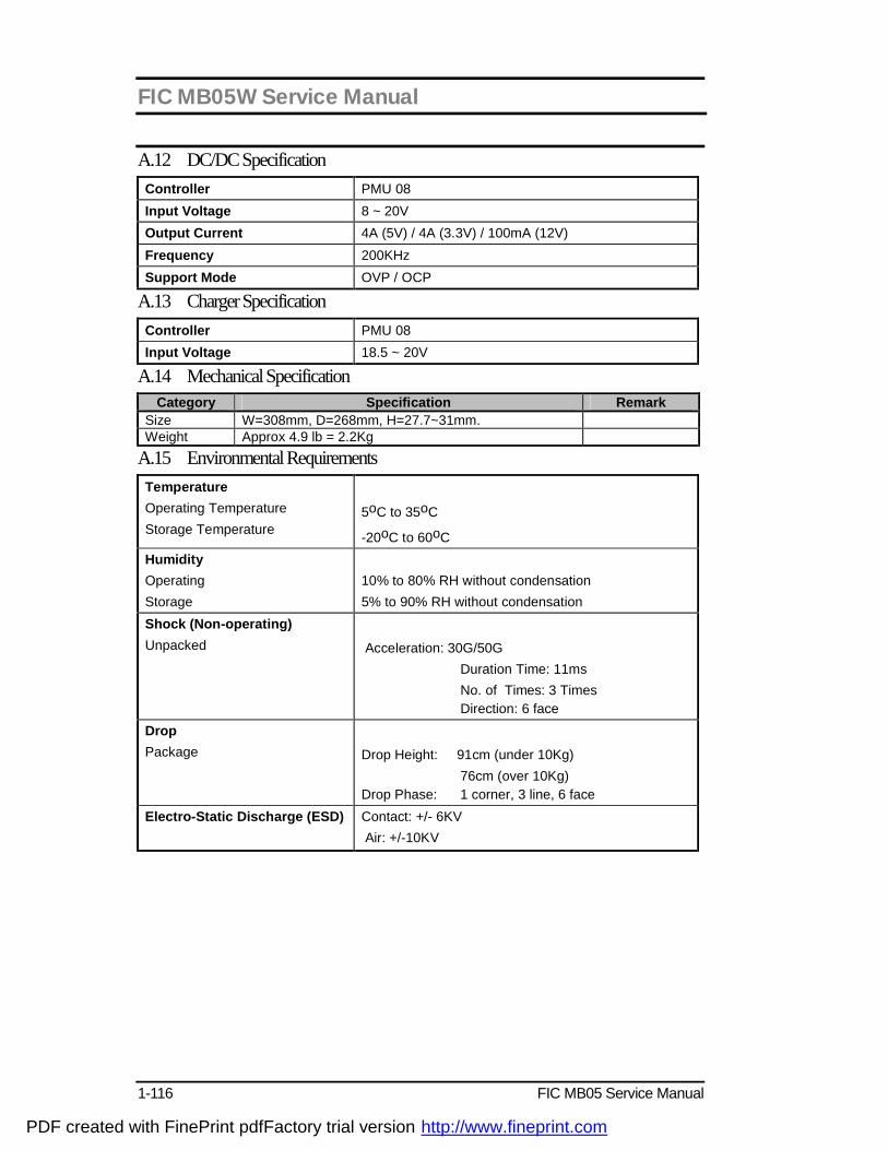
FIC MB05W Service Manual
1-116 FIC MB05 Service Manual
A.12 DC/DC Specification Controller PMU 08 Input Voltage 8 ~ 20V Output Current 4A (5V) / 4A (3.3V) / 100mA (12V) Frequency 200KHz Support Mode OVP / OCP
A.13 Charger Specification Controller PMU 08 Input Voltage 18.5 ~ 20V
A.14 Mechanical Specification Category Specification Remark
Size W=308mm, D=268mm, H=27.7~31mm. Weight Approx 4.9 lb = 2.2Kg
A.15 Environmental Requirements Temperature Operating Temperature Storage Temperature
5oC to 35oC
-20oC to 60oC Humidity Operating Storage
10% to 80% RH without condensation 5% to 90% RH without condensation
Shock (Non-operating) Unpacked
Acceleration: 30G/50G Duration Time: 11ms No. of Times: 3 Times Direction: 6 face
Drop Package
Drop Height: 91cm (under 10Kg) 76cm (over 10Kg) Drop Phase: 1 corner, 3 line, 6 face
Electro-Static Discharge (ESD)
Contact: +/- 6KV Air: +/-10KV
PDF created with FinePrint pdfFactory trial version http://www.fineprint.com
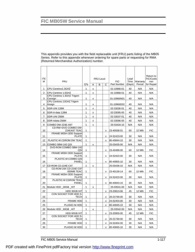
FIC MB05W Service Manual
FIC MB05 Service Manual 1-117
This appendix provides you with the field replaceable unit (FRU) parts listing of the MB05 Series. Refer to this appendix whenever ordering for spare parts or requesting for RMA (Returned Merchandise Authorization) number.
FRU Level
ITEM
FRU
Q'ty A B C
FIC
Part Number
Lead Time
(Days)
Warranty
Period
Return to FIC/Custo
mer for Repair
1 CPU Centrino1.3GHZ 1 x 01-10966-01 40 N/A N/A
2 CPU Centrino 1.5GHZ 1 x 01-10968-01 40 N/A N/A
3 CPU Centrino 1.3GHZ Trigem Consign 1 x 01-10966N01 40 N/A N/A
4 CPU Centrino 13GHZ Trigem Assign 1 x 01-10966D02 40 N/A N/A
5 DDR-UNI 128M 1 x 02-33036-01 40 N/A N/A
6 DDR-A-data 128M 1 x 02-33095-00 40 N/A N/A
7 DDR-UNI 256M 1 x 02-33037-01 40 N/A N/A
8 DDR-Adata 256M 1 x 02-33096-00 40 N/A N/A
9 COMBO DW-224E-A97 1 x 25-03434-10 N/A N/A N/A
10 CD-RW+DVD COMBO DW-
224EA97 TEAC 1 x 23-40558-01 60 12 Mth FIC
11 FRAME M05H ODD Support
PLATE 1 x 24-52423-00 30 N/A N/A
12 PLASTIC-M CDROM DW TEAC 1 x 80-40844-10 30 N/A N/A
13 COMBO SBW-242 QSI 1 x 25-03435-00 N/A N/A N/A
14 DVD-ROM COMBO SBW-242
QSI 1 x 23-40489-00 60 12 Mth FIC
15 FRAME M05H ODD Support
PLATE 1 x 24-52423-00 30 N/A N/A
16 PLASTIC-M COMBO QSI
PANEL 1 x 80-40855-10 30 N/A N/A
17 CD-ROM CD-224E-C97 1 x 25-03436-10 N/A N/A N/A
18 CD-ROM 24X CD-224E-C97
650MB TEAC 1 x 23-40139-14 60 12 Mth FIC
19 FRAME M05H ODD Support
PLATE 1 x 24-52423-00 30 N/A N/A
20 PLASTIC-M CDROM TEAC
PANEL 1 x 80-40843-10 30 N/A N/A
21 Module HDD _30GB _HIT 1 x 25-03541-00 N/A N/A N/A
22 HDD 30GB HIT 1 x 23-20813-06 45 12 Mth FIC
23 CON SOCKET FOR HDD S-
TECH 1 x 20-21749-00 30 N/A N/A
24 FRAME HDD 1 x 24-52404-00 30 N/A N/A
25 PLASIIC-M HDD 1 x 80-40845-10 30 N/A N/A
26 Module HDD _60GB _HIT 1 x 25-03542-00 N/A N/A N/A
27 HDD 60GB HIT 1 x 23-20900-00 45 12 Mth FIC
28 CON SOCKET FOR HDD S-
TECH 1 x 20-21749-00 30 N/A N/A
29 FRAME HDD 1 x 24-52404-00 30 N/A N/A
30 PLASIIC-M HDD 1 x 80-40845-10 30 N/A N/A
PDF created with FinePrint pdfFactory trial version http://www.fineprint.com
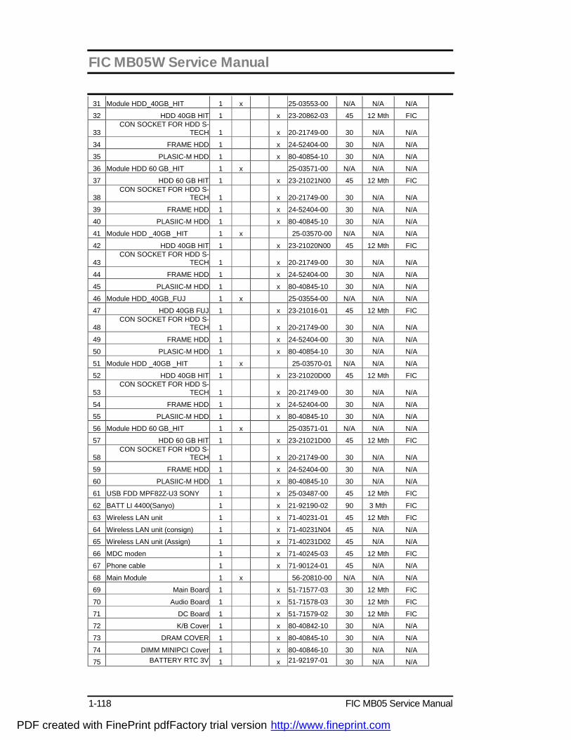
FIC MB05W Service Manual
1-118 FIC MB05 Service Manual
31 Module HDD_40GB_HIT 1 x 25-03553-00 N/A N/A N/A
32 HDD 40GB HIT 1 x 23-20862-03 45 12 Mth FIC
33 CON SOCKET FOR HDD S-
TECH 1 x 20-21749-00 30 N/A N/A
34 FRAME HDD 1 x 24-52404-00 30 N/A N/A
35 PLASIC-M HDD 1 x 80-40854-10 30 N/A N/A
36 Module HDD 60 GB_HIT 1 x 25-03571-00 N/A N/A N/A
37 HDD 60 GB HIT 1 x 23-21021N00 45 12 Mth FIC
38 CON SOCKET FOR HDD S-
TECH 1 x 20-21749-00 30 N/A N/A
39 FRAME HDD 1 x 24-52404-00 30 N/A N/A
40 PLASIIC-M HDD 1 x 80-40845-10 30 N/A N/A
41 Module HDD _40GB _HIT 1 x 25-03570-00 N/A N/A N/A
42 HDD 40GB HIT 1 x 23-21020N00 45 12 Mth FIC
43 CON SOCKET FOR HDD S-
TECH 1 x 20-21749-00 30 N/A N/A
44 FRAME HDD 1 x 24-52404-00 30 N/A N/A
45 PLASIIC-M HDD 1 x 80-40845-10 30 N/A N/A
46 Module HDD_40GB_FUJ 1 x 25-03554-00 N/A N/A N/A
47 HDD 40GB FUJ 1 x 23-21016-01 45 12 Mth FIC
48 CON SOCKET FOR HDD S-
TECH 1 x 20-21749-00 30 N/A N/A
49 FRAME HDD 1 x 24-52404-00 30 N/A N/A
50 PLASIC-M HDD 1 x 80-40854-10 30 N/A N/A
51 Module HDD _40GB _HIT 1 x 25-03570-01 N/A N/A N/A
52 HDD 40GB HIT 1 x 23-21020D00 45 12 Mth FIC
53 CON SOCKET FOR HDD S-
TECH 1 x 20-21749-00 30 N/A N/A
54 FRAME HDD 1 x 24-52404-00 30 N/A N/A
55 PLASIIC-M HDD 1 x 80-40845-10 30 N/A N/A
56 Module HDD 60 GB_HIT 1 x 25-03571-01 N/A N/A N/A
57 HDD 60 GB HIT 1 x 23-21021D00 45 12 Mth FIC
58 CON SOCKET FOR HDD S-
TECH 1 x 20-21749-00 30 N/A N/A
59 FRAME HDD 1 x 24-52404-00 30 N/A N/A
60 PLASIIC-M HDD 1 x 80-40845-10 30 N/A N/A
61 USB FDD MPF82Z-U3 SONY 1 x 25-03487-00 45 12 Mth FIC
62 BATT LI 4400(Sanyo) 1 x 21-92190-02 90 3 Mth FIC
63 Wireless LAN unit 1 x 71-40231-01 45 12 Mth FIC
64 Wireless LAN unit (consign) 1 x 71-40231N04 45 N/A N/A
65 Wireless LAN unit (Assign) 1 x 71-40231D02 45 N/A N/A
66 MDC moden 1 x 71-40245-03 45 12 Mth FIC
67 Phone cable 1 x 71-90124-01 45 N/A N/A
68 Main Module 1 x 56-20810-00 N/A N/A N/A
69 Main Board 1 x 51-71577-03 30 12 Mth FIC
70 Audio Board 1 x 51-71578-03 30 12 Mth FIC
71 DC Board 1 x 51-71579-02 30 12 Mth FIC
72 K/B Cover 1 x 80-40842-10 30 N/A N/A
73 DRAM COVER 1 x 80-40845-10 30 N/A N/A
74 DIMM MINIPCI Cover 1 x 80-40846-10 30 N/A N/A
75 BATTERY RTC 3V 1 x 21-92197-01 30 N/A N/A
PDF created with FinePrint pdfFactory trial version http://www.fineprint.com

FIC MB05W Service Manual
FIC MB05 Service Manual 1-119
76 SPEAKER +CABLE 1 x 21-20779-00 30 N/A N/A
77 HEAT SINK FOR CPU 1 x 24-20705-00 30 N/A N/A
78 HEAT SINK MB02 NORTH
BRIDGE 1 x 24-20687-00 30 N/A N/A
79 Module Bottom cover 1 x 80-40847-10 N/A N/A N/A
80 CASE BOTTOM 1 x 24-45816-10 35 N/A N/A
81 CASE PCMCIA DOOR 1 x 24-45817-10 35 N/A N/A
82 FRAME SLIDE PLT FOR
BATTERY 1 x 24-52412-00 35 N/A N/A
83 FRAME HDD
BRACKET(BOTTEN SIDE) 1 x 24-52403-00 35 N/A N/A
84 RUBBER FOOT 1 x 24-84611-00 35 N/A N/A
85 RUBBER CIRCLE 1 x 24-84569-00 35 N/A N/A
86 Metal-M Topcover Plat Thermal 1 x 80-50238-00 35 N/A N/A
87 MUDULE PALM-REST 1 x 25-03559-00 N/A N/A N/A
8 F-CABLE MB05H SWITCH FPC 1 x 22-21321-00 35 N/A N/A
89 SW/ Board 1 x 51-71581-03 35 N/A N/A
90 GLIDE PAD KGDDFT014A 1 x 71-23017-00 35 N/A N/A
91 PLASTIC-M TOP COVER 1 x 80-40841-10 35 N/A N/A
92 METAL-M MB05H G/P 1 x 80-50233-00 35 N/A N/A
93 Module LCD TFT 15' HAN 1 x 56-10684-10 N/A N/A N/A
94 LCD 15" MONITOR 15.0INCH
TFT XGA HAN 1 x 71-10681-00 60 12 Mth FIC
95 INVT /B 1 x 12-01614-01 60 12 Mth FIC
96 WIRE MB05H COAXIAL
CABLE15" HAN 1 x 22-11144-00 60 N/A N/A
97 CASE HINGE COVER 1 x 24-45798-10 30 N/A N/A
98 RUBBER LCD UPPER 1 x 24-84515-00 30 N/A N/A
99 LCD BEZEL 15" 1 x 80-40839-10 30 N/A N/A
100 LCD 15"Back Cover 1 x 80-40840-10 30 N/A N/A
101 Module LCD TFT 15" LG 1 x 56-10703-10 N/A N/A N/A
102 LCD 15" TFT XGA LP150X05-
C2 LG 1 x 71-10676-10 60 12 Mth FIC
103 INVT/B 1 x 12-01614-01 60 12 Mth FIC
104 WIRE MB05H COAXIAL
CABLE15" HAN 1 x 22-11144-00 60 N/A N/A
105 CASE HINGE COVER 1 x 24-45798-10 30 N/A N/A
106 RUBBER LCD UPPER 1 x 24-84515-00 30 N/A N/A
107 LCD BEZEL 15" 1 x 80-40839-10 30 N/A N/A
108 LCD 15"Back Cover 1 x 80-40840-10 30 N/A N/A
109 HINGE_L_15" 1 x 24-84519-00 30 N/A N/A
110 HINGE_R_15" 1 x 24-84517-00 30 N/A N/A
111 Module LCD TFT 15" AU 1 x 56-10707-00 N/A N/A N/A
112 LCD 15INCH TFT XGA
B150XG01-2 AU 1 x 71-10726-00 60 12 Mth FIC
113 INVT TBD141N TDK FOR
MB05H 1 x 12-01614-01 60 12 Mth FIC
114 WIRE MB05H COAXIAL
CABLE15" HAN 1 x 22-11144-00 60 N/A N/A
115 RUBBER LCD UPPER 1 x 24-84515-00 30 N/A N/A
116 LCD BEZEL 15" 1 x 80-40839-10 30 N/A N/A
117 LCD 15"Back Cover 1 x 80-40840-10 30 N/A N/A
118 HINGE_L_15" 1 x 24-84519-00 30 N/A N/A
119 HINGE_R_15" 1 x 24-84517-00 30 N/A N/A
PDF created with FinePrint pdfFactory trial version http://www.fineprint.com

FIC MB05W Service Manual
1-120 FIC MB05 Service Manual
120 POWER CORD (JAP) 1 x 22-30135-06 30 N/A N/A
121 POWER CORD (US) 1 x 22-30135-15 30 N/A N/A
122 POWER CORD (UK) 1 x 22-30135-16 30 N/A N/A
123 POWER CORD(EUR) 1 x 22-30135-17 30 N/A N/A
124 POWER CORD(Korea) 1 x 22-301135-18 30 N/A N/A
125 ADAPTOR 60W FIC DELAT ADP-60NH 1 x 12-01618-02 35 12 Mth FIC
126 Keyboard(JAP) 1 x 71-31705-00 35 12 Mth FIC
127 Keyboard(US) 1 x 71-31705-01 35 12 Mth FIC
128 Keyboard(Canada) 1 x 71-31705-04 35 12 Mth FIC
129 Keyboard(UK) 1 x 71-31705-05 35 12 Mth FIC
130 Keyboard(Taiwan) 1 x 71-31705-06 35 12 Mth FIC
131 Keyboard(Korea) 1 x 71-31705-07 35 12 Mth FIC
132 Keyboard(France) 1 x 71-31705-09 35 12 Mth FIC
133 Keyboard(GR) 1 x 71-31705-11 35 12 Mth FIC
PDF created with FinePrint pdfFactory trial version http://www.fineprint.com