
Mazda RX-8 2004-2008 Table of Contents 99-7510, 99 … · nstrucciones de instalación para la...
16
METRA - The World’s best kits ® metraonline.com REV. 12/21/2016 INST99-7510 Installation instructions for part 99-7510 ® CAUTION! All accessories, switches, climate controls panels, and especially air bag indicator lights must be connected before cycling the ignition. Also, do not remove the factory radio with the key in the on position, or while the vehicle is running. © COPYRIGHT 2016 METRA ELECTRONICS CORPORATION • DIN radio provision with pocket • ISO DIN radio provision with pocket • Two finishes available: 99-7510 = Black 99-7510HG = Gloss Black • A) Radio/climate control housing • B) ISO DIN brackets • C) ISO DIN trim plate • D) (4) Plastic panel clips • E) Axxess Interface and wiring harness (not shown) KIT FEATURES KIT COMPONENTS WIRING & ANTENNA CONNECTIONS Wiring Harness: • Axxess interface and wiring harness included Antenna Adapter: • Not required • Panel removal tool • Phillips screwdriver • 10mm socket wrench • Cutting tool TOOLS REQUIRED Mazda RX-8 2004-2008 99-7510, 99-7510HG A B C D Dash Disassembly ................................................. 2 Kit Preparation .................................................... 3-4 Kit Assembly – DIN radio provision with pocket ............................ 4 – ISO DIN radio provision with pocket...................... 5 Axxess Interface Installation ............................. 5-7 Display Customization........................................ 7-8 Table of Contents
Transcript of Mazda RX-8 2004-2008 Table of Contents 99-7510, 99 … · nstrucciones de instalación para la...

METRA - The World’s best kits ® metraonline.com
REV.
12/
21/2
016
INS
T99-
7510
Installation instructions for part 99-7510
®
CAUTION! All accessories, switches, climate controls panels, and especially air bag indicator lights must be connected before cycling the ignition. Also, do not remove the factory radio with the key in the on position, or while the vehicle is running.
© COPYRIGHT 2016 METRA ELECTRONICS CORPORATION
• DIN radio provision with pocket • ISO DIN radio provision with pocket• Two finishes available: 99-7510 = Black 99-7510HG = Gloss Black
• A) Radio/climate control housing • B) ISO DIN brackets • C) ISO DIN trim plate • D) (4) Plastic panel clips• E) Axxess Interface and wiring harness (not shown)
KIT FEATURES
KIT COMPONENTS
WIRING & ANTENNA CONNECTIONSWiring Harness: • Axxess interface and wiring harness included
Antenna Adapter: • Not required
• Panel removal tool • Phillips screwdriver • 10mm socket wrench • Cutting tool
TOOLS REQUIRED
Mazda RX-8 2004-200899-7510, 99-7510HG
A B C D
Dash Disassembly ................................................. 2
Kit Preparation ....................................................3-4
Kit Assembly
– DIN radio provision with pocket ............................ 4
– ISO DIN radio provision with pocket ...................... 5
Axxess Interface Installation .............................5-7
Display Customization ........................................7-8
Table of Contents
99-7510
®
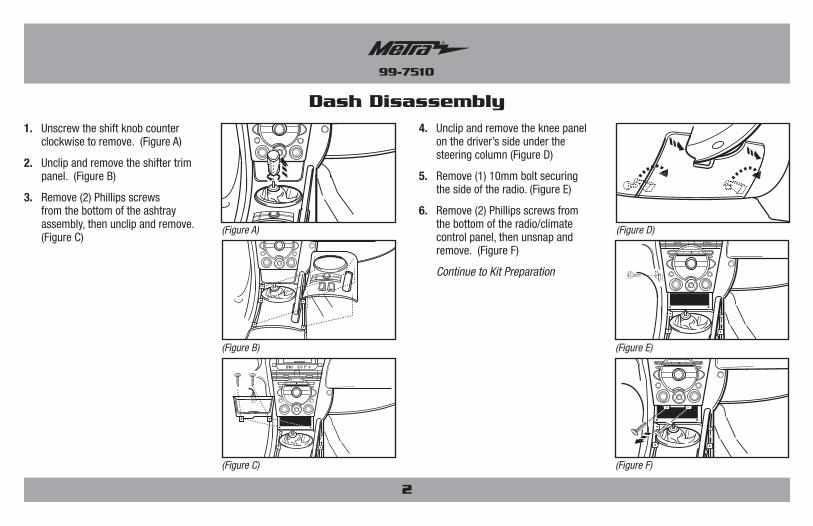
1. Unscrew the shift knob counter clockwise to remove. (Figure A)
2. Unclip and remove the shifter trim panel. (Figure B)
3. Remove (2) Phillips screws from the bottom of the ashtray assembly, then unclip and remove. (Figure C)
Dash DisassemblyFM1 877 AC
FM1 877 AC
FM1 877 AC
FM1 877 AC
FM1 877 AC
(Figure A) (Figure D)
(Figure B) (Figure E)
(Figure C) (Figure F)
2
4. Unclip and remove the knee panel on the driver’s side under the steering column (Figure D)
5. Remove (1) 10mm bolt securing the side of the radio. (Figure E)
6. Remove (2) Phillips screws from the bottom of the radio/climate control panel, then unsnap and remove. (Figure F)
Continue to Kit Preparation

99-7510
®
Kit Preparation
REMOVE (2) SCREWS PER SIDE
(Figure I)
(Figure H)
(Figure J) (Figure L)
(Figure K)
3
From the factory radio/climate control panel:
1. Remove (3) screws securing the display harness. This harness will be reused in kit assembly. (Figure H)
2. Remove (4) screws securing the radio chassis, and then remove. (Figure I)
3. Remove (6) screws securing the climate controls, and then remove. The controls and hardware will be reused in kit assembly. (Figure J)
4. Remove (17) screws securing the circuit board to access the hazard switch assembly. (Figure K)
5. Remove (2) screws securing the hazard switch assembly. Carefully pull and release the hazard switch button from the assembly to fully remove the complete assembly. The switch and hardware will be reused in kit assembly. (Figure L)
Continue to the next page
99-7510
®
4
Kit AssemblyKit PreparationTo the 99-7510 radio/climate
control housing:
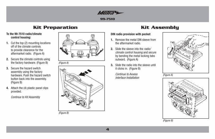
1. Cut the top (2) mounting locations off of the climate controls to provide clearance for the aftermarket radio. (Figure A)
2. Secure the climate controls using the factory hardware. (Figure B)
3. Secure the hazard switch assembly using the factory hardware. Push the hazard switch button back into the assembly. (Figure B)
4. Attach the (4) plastic panel clips provided.
Continue to Kit Assembly
(Figure A)
(Figure A)
(Figure B)
(Figure B)
0 1 2
3
4
A/C
DIN radio provision with pocket
1. Remove the metal DIN sleeve from the aftermarket radio.
2. Slide the sleeve into the radio/climate control housing and secure by bending the metal locking tabs outward. (Figure A)
3. Slide the radio into the sleeve until it clicks in. (Figure B)
Continue to Axxess Interface Installation

99-7510
®
5
Kit Assembly Axxess Interface Installation
(Figure A)
(Figure B)
ISO DIN radio provision with pocket
1. Remove the metal DIN sleeve and trim ring from the aftermarket radio.
2. Secure the ISO DIN brackets to the radio using the screws supplied with the radio. (Figure A)
3. Slide the radio into the radio/climate control housing until it snaps into place. (Figure B)
4. Snap the ISO DIN trim plate into the radio/climate control housing. (Figure B)
Continue to Axxess Interface Installation
• Provides NAV outputs (parking brake, reverse, speed sense)• Can be used in both amplified and non-amplified models• Retains balance and fade• USB-CAB updatable (sold separately)
Connections to be made ...................................................6Installing the interface .....................................................7Display Customization .................................................. 7-8
• 7510 harness • OBDII harness with stripped leads• Hazard switch extension cable • Climate control extension harnesses (2)
INTERFACE FEATURES
TABLE OF CONTENTS
INTERFACE COMPONENTS
• Wire Cutter • Crimp tool • Solder gun • Tape• Connectors (example: butt-connectors, bell caps, etc.)
TOOLS REQUIRED

99-7510
®
6
1 2 3 4 5 6 7 89 10 11 12 13 14 15 16
PINK WIREOBDII CONNECTOR FACE VIEW
PINK/BLUE WIRE
The following steps are only for multimedia/navigation radios that require these wires.
• Connect the Blue/Pink wire to the VSS/speed sense wire.
• Connect the Green/Purple wire to the reverse wire.
Note: Not applicable on manual transmission vehicles.
• Connect the Light Green wire to the parking brake wire.
• Connect the ODBII harness with stripped leads, to the 2-pin harness.
• Run the wires from ODBII harness with stripped leads to the ODBII connector in the vehicle, and then connect them as shown.
Connections to be madeFrom the 7510 harness to the aftermarket radio:
• Connect the Black wire to the ground wire.
• Connect the Yellow wire to the battery wire.
• Connect the Red wire to the accessory wire.
• Connect the Blue wire to the power antenna wire.
• If the vehicle is equipped with a factory amplifier, connect the Blue/White wire to the amp turn on wire. This wire must be connected to hear sound from the factory amplifier.
• If the aftermarket radio has an illumination wire, connect the Orange wire to it.
• Tape off and disregard the Orange/White wire, it will not be used in this application.
• Connect the Gray wire to the right front positive speaker output.
• Connect the Gray/Black wire to the right front negative speaker output.
• Connect the White wire to the left front positive speaker output.
• Connect the White/Black wire to the left front negative speaker output.
• Connect the Green wire to the left rear positive speaker output.
• Connect the Green/Black wire to the left rear negative speaker output.
• Connect the Purple wire to the right rear positive speaker output.
• Connect the Purple/Black wire to the right rear negative speaker output.

99-7510
®
7
1. Press and hold the A/C Mode button to scroll through the various kit options (AMB TEMP ON or OFF, AMB TEMP C or F, SET TIME 12/24H, and SET TEXT).
2. When you see the option you want just let the button go and the action on the screen will be performed. (ie: To turn the ambient temperature on you would scroll through until the display says “AMB TEMP ON” and let the button go.)
3. To set the time hold down the A/C Mode button until the display says “SET TIME 12/24H” then let the button go.
4. To switch between 12H and 24H press the front defrost button to the left of the A/C Mode button.
Continued on the next page
Display Customization
FM1 877 AC
02
3
4
OPENTILT
A/C
MODE
1
FM1 877 AC
02
3
4
OPENTILT
A/C
MODE
1
Installing the interface
1. Attach the (2) climate control extension harnesses to the temperature control cable, and the fan control cable, on the factory climate control.
2. Plug the temperature control cable from the factory climate control into the port on the interface labeled “TEMP”. (Figure A)
3. Plug the fan control cable from the factory climate control into the port on the interface labeled “FAN”. (Figure B)
4. Plug the display harness removed in step 1 of kit preparation into the port on the interface labeled “DISP”. (Figure B)
5. Plug the hazard switch extension cable to the factory hazard switch, and then into the port on the interface labeled “HAZARD”. (Figure B)
6. Test all functions of the installation for proper operation, before reassembling the dash.
Note: If the vehicle is equipped with automatic climate controls, start the vehicle and hold the “AUTO” button for 10 seconds to program the climate controls.
7. Reassemble the dash in reverse order of disassembly
(Figure A)
(Figure B)
Attention!: Failure to insert the HVAC cables into the correct location will cause damage to the interface and make the display and HVAC controls not function properly.

METRA - The World’s best kits ® metraonline.com © COPYRIGHT 2016 METRA ELECTRONICS CORPORATION
REV.
12/
21/2
016
INS
T99-
7510
KNOWLEDGE IS POWEREnhance your installation and fabrication skills by enrolling in the most recognized and respected mobile electronics school in our industry.Log onto www.installerinstitute.com or call 800-354-6782 for more information and take steps toward a better tomorrow.
Metra recommends MECP certified technicians
Installation instructions for part 99-7510
®
IMPORTANTIf you are having difficulties with the installation of this product, please call our Tech Support line at 1-800-253-TECH. Before doing so, look over the instructions a second time, and make sure the installation was performed exactly as the instructions are stated. Please have the vehicle apart and ready to perform troubleshooting steps before calling.
5. To change the Hour press the rear defrost button to the right of the A/C Mode button.
6. To change the minute press the A/C button at the top of the A/C Mode button.
7. At any time if you do not press any buttons for 5-seconds the display will save and return to the default screen and the climate control buttons will return to their normal configuration.
8. If you hold the A/C Mode button down long enough the display will say “SET TEXT”. This will allow you customize the default text on the display.
9. Once the display says “SET TEXT” let go and the first letter of the display will begin blinking.
10. Press the front defrost button to move the cursor left and the rear defrost button to move the cursor to the right.
11. You can scroll up with the A/C button and down with the Recirc/Fresh button through the various alpha, numeric, and symbol characters.
12. When you are finished entering your text if you do not press any buttons for 5-seconds the display will save and return to the default screen and the climate control buttons will return to their normal configuration.
Display Customization (Cont)

METRA - The World’s best kits ® metraonline.com
REV.
12/
21/2
016
INS
T99-
7510
Instrucciones de instalación para la pieza 99-7510
®
¡PRECAUCIÓN! Todos los accesorios, interruptores, paneles de con-troles de clima y especialmente las luces del indicador de las bolsas de aire deben estar conectados antes ciclar la ignición. Además, no quite el radio de fábrica con la llave en la posición o de encendido ni con el vehículo funcionando.
© COPYRIGHT 2016 METRA ELECTRONICS CORPORATION
• Provisión de radio DIN con cavidad • Provisión de radio ISO DIN con cavidad• Dos acabados disponibles: 99-7510 = Negro 99-7510HG = Negro brillante
• A) Carcasa de radio/control de clima • B) Soportes ISO DIN • C) Placa de moldura ISO DIN• D) (4) Ganchos blancos del panel • E) Interfase Axxess y arnés de cables (no se muestra)
CARACTERÍSTICAS DEL KIT
COMPONENTES DEL KIT
CABLEADO Y CONEXIONES DE ANTENAArnés de cableado: • Interfase Axxess y arnés de cableado incluido
Adaptador de antena: • No se requiere
• Herramienta de remoción de panel • Destornillador Phillips • llave de tubo 10mm • Herramienta de corte
HERRAMIENTAS REQUERIDAS
Mazda RX-8 2004-200899-7510, 99-7510HG
A B C D
Desmontaje del tablero ......................................... 2
Preparación del kit .............................................3-4
Ensamble del kit
– Provisión de radio DIN con cavidad ...................... 4
– Provisión de radio ISO DIN con cavidad ................ 5
Instalación de la interfase Axxess .....................5-7
Personalización de la pantalla ...........................7-8
Indice

99-7510
®
1. Desatornille el contador de la perilla de la palanca de velocidades hacia la izquierda para quitarlo. (Figura A)
2. Desenganche y quite el panel de moldura de la palanca de velocidades. (Figura B)
3. Quite los (2) tornillos Phillips de la parte inferior del ensamble del cenicero, y luego desenganche y quite. (Figura C)
Desmontaje del tableroFM1 877 AC
FM1 877 AC
FM1 877 AC
FM1 877 AC
FM1 877 AC
(Figura A) (Figura D)
(Figura B) (Figura E)
(Figura C) (Figura F)
2
4. Desenganche y quite el panel para las rodillas del lado del conductor debajo de la columna de dirección (Figura D)
5. Retire (1) perno de 10mm que asegura el lado de la radio. (Figura E)
6. Quite los (2) tornillos Phillips de la parte inferior de la radio/ panel del control de clima, y luego desenganche y quite. (Figura F)
Continúe con la preparación del kit

99-7510
®
Preparación del kit
REMOVE (2) SCREWS PER SIDE
(Figura I)
(Figura H)
(Figura J) (Figura L)
(Figura K)
3
Desde la radio de fábrica/panel del control del clima :
1. Quite (3) los tornillos que aseguran el arnés de la pantalla. Este arnés será reutilizado en el conjunto del kit. (Figura H)
2. Quite los (4) tornillos Phillips que sujetan el chasís del radio, y luego quite. (Figura I)
3. Quite los (6) tornillos Phillips que aseguran los controles del clima, luego quite. Los controles y el hardware serán reutilizados en el conjunto del kit. (Figura J)
4. Retire los (17) tornillos que aseguran la placa de circuito para acceder al conjunto de interruptor de peligro. (Figura K)
5. Quite (2) los tornillos que sujetan el conjunto del interruptor de peligro. Tire con cuidado y suelte el botón interruptor de peligro del conjunto para eliminar por completo el conjunto completo. El switch y el hardware serán reutilizados en el conjunto del kit. (Figura L)
Continua en la siguiente pagina

99-7510
®
4
Ensamble del kitPreparación del kitA la radio 99-7510/carcasa de
control climático:
1. Corte la parte superior (2) de los lugares de montaje fuera de los controles de clima para proporcionar espacio libre para radio de mercado secundario. (Figura A)
2. Asegure los controles de clima usando el hardware de la fábrica. (Figura B)
3. Asegure el conjunto del interruptor de peligro usando el hardware de fábrica. Pulsar el botón interruptor de peligro de nuevo en el conjunto. (Figura B)
4. Conecte los (4) clips de plástico del panel.
Continúe con el ensamble del kit
(Figura A)
(Figura A)
(Figura B)
(Figura B)
0 1 2
3
4
A/C
Provisión de radio DIN con cavidad
1. Quite la manga de metal DIN del radio de mercado secundario.
2. Deslice la manga en la radio/carcasa de control climático y sujétela doblando hacia abajo las pestañas de metal. (Figura A)
3. Deslice el radio en la manga hasta que haga clic. (Figura B)
Continúe con Instalación de la interfase Axxess

99-7510
®
5
Ensamble del kit Instalación de la interfase Axxess
(Figura A)
(Figura B)
Provisión de radio ISO DIN con cavidad
1. Quite la manga de metal DIN y el anillo de moldura del radio de mercado secundario.
2. Atornille los soportes ISO DIN al radio usando los tornillos suministrados con el radio. (Figura A)
3. Deslice el radio en el radio/ carcasa de control climático hasta que entre a presión. (Figura B)
4. Coloque a presión la placa de la moldura ISO DIN en la radio/carcasa de control climático. (Figura B)
Continúe con Instalación de la interfase Axxess
• Proporciona salidas de NAV (freno de mano, reversa y sensor de velocidad)• Puede ser utilizado en ambos modelos amplificados y no amplificados• Retiene el balance y la intensidad• Actualizable USB-CAB (se vende por separado)
Conexiones que se deben hacer ......................................6Instalación de la interfase ................................................7Personalización de la pantalla ..................................... 7-8
• Arnés 7510 • Arnés OBDII con conectores pelados• Cable de extensión del interruptor de peligro• Arnés de extensión de control climático (2)
CARACTERÍSTICAS DE LA INTERFASE
INDICE
COMPONENTES DEL KIT
• Cortacables • Ponchadora • Pistola soldadora • Cinta• Conectores (ejemplo: conectores de extremo, de campana, etc.)
HERRAMIENTAS REQUERIDAS

99-7510
®
6
Los siguientes pasos son sólo para radios con multimedios/navegación que tienen estos cables.
• Conecte el cable azul/rosa al cable VSS o de detección de velocidad.
• Conecte el cable verde/púrpura al cable de reversa.
Nota: No aplicable a los vehículos de transmisión manual.
• Conecte el cable verde claro al cable de freno de mano.
• Conecte el arnés ODBII con conectores pelados, al arnés 2-pin.
• Ejecute los cables del arnés ODBII con conectores pelados al conector ODBII del vehículo y, a continuación, conéctelos como se muestra.
Conexiones que se deben hacerDesde el arnés 7510 al radio de mercado secundario:
• Conecte el cable negro al cable de tierra.
• Conecte el cable amarillo al cable de la batería.
• Conecte el cable rojo con el cable de accesorios.
• Conecte el cable azul al cable de la antena eléctrica.
• Si el vehículo está equipado con un amplificador de fábrica, conecte el cable azul/blanco con el cable de encendido del amplificador. Este cable debe estar conectado para escuchar sonido del amplificador de fábrica.
• Si el radio de mercado secundario tiene un cable de iluminación, conecte el cable anaranjado a ella.
• Encinte e ignore el cable anaranjado/blanco, no se utilizarán en esta aplicación.
• Conecte el cable gris con la salida positiva de la bocina derecha delantera.
• Conecte el cable gris/negro con la salida negativa de la bocina derecha delantera.
• Conecte el cable blanco con la salida positiva de la bocina izquierda delantera.
• Conecte el cable blanco/negro con la salida negativa de la bocina izquierda delantera.
• Conecte el cable verde con la salida positiva de la bocina izquierda trasera.
• Conecte el cable verde/negro con la salida negativa de la bocina izquierda trasera.
• Conecte el cable púrpura con la salida positiva de la bocina derecha trasera.
• Conecte el cable púrpura/negro con la salida negativa de la bocina derecha trasera.
1 2 3 4 5 6 7 89 10 11 12 13 14 15 16
PINK WIREOBDII CONNECTOR FACE VIEW
PINK/BLUE WIRE
Vista de frente del conector OBDII
Cable rosa
Cable rosa/azul

99-7510
®
7
1. Presione y mantenga presionado el botón de modo de A/C para desplazarse por las distintas opciones del kit (AMB TEMP ON u OFF, AMB TEMP C o F, SET TIME 12/24H, y SET TEXT).
2. Cuando vea la opción deseada, suelte el botón y se ejecutará la acción que se ve en pantalla. (es decir: para encender la temperatura ambiente, debe desplazarse hasta que la pantalla indique “AMB TEMP ON” y soltar el botón).
3. Para poner la hora, mantenga presionado el botón de modo A/C hasta que la pantalla indique “SET TIME 12/24H” y suelte el botón.
4. Para cambiar entre el formato de 12H y 24H, presione el botón de deshielo a la izquierda del botón de modo A/C.
Continua en la siguiente pagina
Personalización de la pantalla
FM1 877 AC
02
3
4
OPENTILT
A/C
MODE
1
FM1 877 AC
02
3
4
OPENTILT
A/C
MODE
1
Instalación de la interfase
1. Una los (2) arneses de extensión del control de clima al cable de control de temperatura, y el cable de control del abanico, en el control de clima de fábrica.
2. Conecte el cable del control de temperatura del control de clima de fábrica en el puerto de la interfase que dice “TEMP”. (Figura A)
3. Conecte el cable de control del abanico del control de clima de fábrica en el puerto de la interfase que dice “FAN”. (Figura B)
4. Conecte el cable de la pantalla que quitó en el paso 1 del preparación del kit en el puerto de la interfase que dice “DISP”. (Figure B)
5. Conecte el cable de extensión del interruptor de peligro al interruptor de peligro de fábrica, y luego al puerto de la interfase denominado “HAZARD”. (Figura B)
6. Pruebe todas las funciones de la instalación para su correcto funcionamiento, antes de volver a montar el tablero.
Nota: Si el vehículo está equipado con controles climáticos automáticos, encienda el vehículo y mantenga presionado el botón “AUTO” durante 10 segundos para programar los controles del clima.
7. Vuelva a armar el tablero al revés de como lo desarmó.
(Figura A)
(Figura B)
Atención!: Si no inserta los cables HVAC en la ubicación correcta, se dañará la interfaz y no funcionará correctamente la pantalla y los controles HVAC.

METRA - The World’s best kits ® metraonline.com © COPYRIGHT 2016 METRA ELECTRONICS CORPORATION
REV.
12/
21/2
016
INS
T99-
7510
KNOWLEDGE IS POWEREnhance your installation and fabrication skills by enrolling in the most recognized and respected mobile electronics school in our industry.Log onto www.installerinstitute.com or call 800-354-6782 for more information and take steps toward a better tomorrow.
Metra recomienda técnicos con certificación del Programa de Certificación en Electrónica Móvil (Mobile Electronics Certification Program, MECP).
EL CONOCIMIENTO ES PODERMejore sus habilidades de instalación y fabricación inscribiéndose en la escuela de dispositivos electrónicos móviles más reconocida y respetada de nuestra industria. Regístrese en www.installerinstitute.com o llame al 800-354-6782 para obtener más información y avance hacia un futuro mejor.
Instrucciones de instalación para la pieza 99-7510
®
IMPORTANTESi tiene dificultades con la instalación de este producto, llame a nuestra línea de soporte técnico al 1-800-253-TECH. Antes de hacerlo, revise las instrucciones por segunda vez y asegúrese de que la instalación se haya realizado exactamente como se indica en las instrucciones. Por favor tenga el vehículo desarmado y listo para ejecutar los pasos de resolución de problemas antes de llamar.
5. Para cambiar la hora, presione el botón de deshielo trasero a la derecha del botón de modo A/C.
6. Para cambiar los minutos, presione el botón de A/C arriba del botón de modo A/C.
7. En cualquier momento dado, si no presiona ningún botón durante 5 segundos, la pantalla se guardará y volverá a la pantalla predeterminada y los botones del control de clima volverán a su configuración normal.
8. Si mantiene presionado el botón de modo A/C suficiente tiempo, la pantalla indicará “SET TEXT”. Esto le permitirá personalizar el texto predeterminado en la pantalla.
9. Cuando la pantalla indique “SET TEXT”, suelte el botón y la primera letra de la pantalla comenzará a parpadear.
10. Presione el botón de deshielo delantero para mover el cursor hacia la izquierda y el botón de deshielo trasero para mover el cursor hacia la derecha.
11. Puede desplazarse hacia arriba con el botón A/C y hacia abajo con el botón Recirc/Fresh, pasando por los distintos caracteres de letras, números y símbolos.
12. Cuando termine de ingresar su texto, si no presiona ningún botón durante 5 segundos, la pantalla se guardará y volverá a la pantalla predeterminada y los botones del control de clima volverán a su configuración normal.
Personalización de la pantalla (Cont)