Mayflower Pipeline Incident Response Mitigation …...ExxonMobil Environmental Services Company...
42
Conestoga-Rovers & Associates 5551 Corporate Blvd., Suite 200 Baton Rouge, Louisiana 70808 August 2014 ● 084949-98 Mayflower Pipeline Incident Response Mitigation Action Construction Work Plan Mayflower, Arkansas Prepared for: ExxonMobil Environmental Services Company
Transcript of Mayflower Pipeline Incident Response Mitigation …...ExxonMobil Environmental Services Company...
Conestoga-Rovers & Associates 5551 Corporate Blvd., Suite 200 Baton Rouge, Louisiana 70808
August 2014 ● 084949-98
Mayflower Pipeline Incident Response Mitigation Action Construction Work Plan Mayflower, Arkansas Prepared for: ExxonMobil Environmental Services Company
ExxonMobil Environmental Services Company Mayflower Pipeline Incident Response Mitigation Action Construction Work Plan
084949-98 August 2014
Table of Contents Page
Section 1.0 Introduction ................................................................................................. 1
Section 2.0 Scope of Work ............................................................................................. 1
2.1 Site Preparation .............................................................................. 1
2.2 Site Personnel ................................................................................. 2
2.3 Sediment Removal Plan .................................................................. 2 2.3.1 Dewatering of the Inlet Channel ............................................................... 2 2.3.2 Sediment Removal, Hauling, and Dewatering ........................................... 2 2.3.5 Area Backfilling .......................................................................................... 3
2.4 Amendment Placement Plan .......................................................... 4 2.4.1 Placement of Amendment Material .......................................................... 4
2.5 Reactive Cap Placement Plan .......................................................... 4 2.5.1 Reactive Cap Material Staging, Mixing, and Loading ................................ 4 2.5.2 Placement of the Cap Materials ................................................................ 4 2.5.3 Temporary Cap Erosion Controls .............................................................. 5
2.6 Environmental Protection Measures .............................................. 5 2.6.1 Water Pollution Control ............................................................................ 5 2.6.2 Noise Controls ........................................................................................... 5 2.6.3 Odor and Dust Control .............................................................................. 5 2.6.4 Refueling Areas ......................................................................................... 6 2.7 Spill Control and Prevention Plan .............................................................. 6
Section 3.0 Project Schedule .......................................................................................... 6
Section 4.0 References ................................................................................................... 7
ExxonMobil Environmental Services Company Mayflower Pipeline Incident Response Mitigation Action Construction Work Plan
084949-98 August 2014
List of Figures (Following Text)
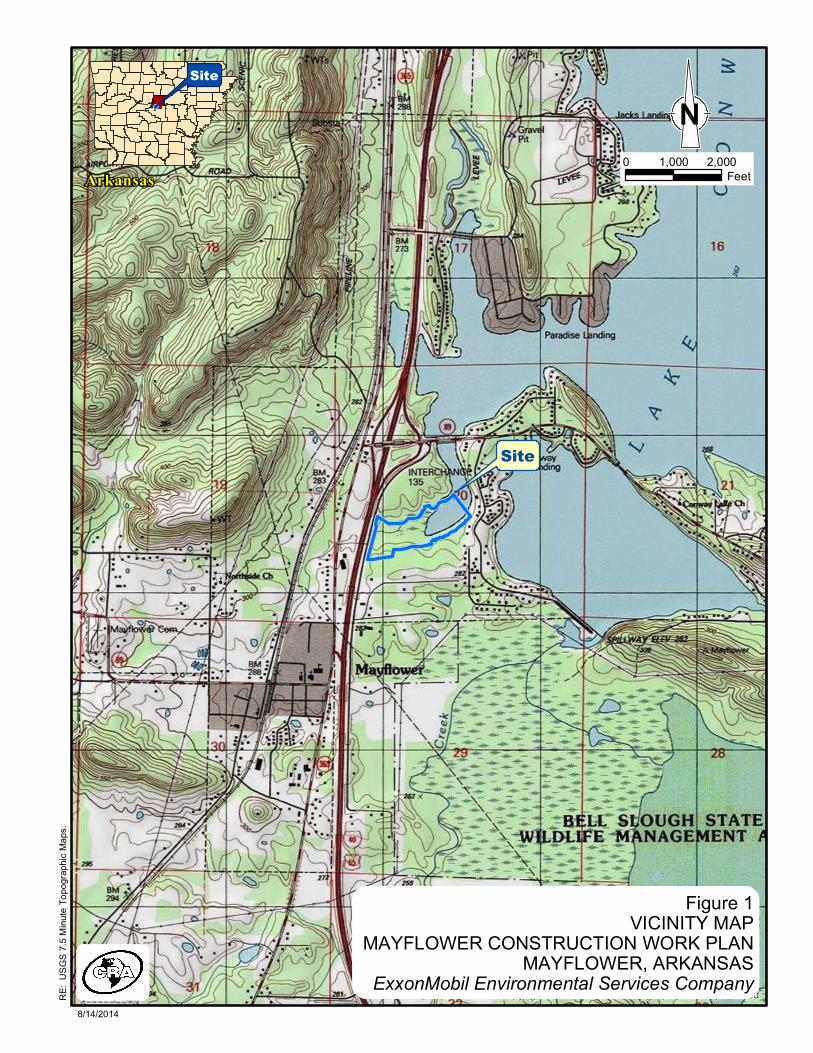
Figure 1 Vicinity Map
Figure 2 Plan View
List of Appendices
Appendix A Stormwater Pollution & Prevention Plan
Appendix B Site Security Plan
Appendix C Traffic Control Plan
Appendix D Construction Schedule
ExxonMobil Environmental Services Company Mayflower Pipeline Incident Response Mitigation Action Construction Work Plan
084949-98
August 2014 1
Section 1.0 Introduction
Conestoga-Rovers & Associates (CRA) submits herein to ExxonMobil Environmental Services Company (EMES) a Construction Work Plan for the Mayflower Pipeline Incident Response Mitigation Action in Mayflower, Arkansas (Site; Figure 1). Section 2.0 Scope of Work
The scope of work for the Mayflower Pipeline Incident Response Mitigation Action includes installation of and improvements to staging areas and access roads, sediment removal and subsequent backfilling within the Inlet Channel, placement of a reactive cap in the Open Water Area, and placement of in-situ amendment within the Heavily Vegetated Area. The activities will be completed in accordance with the Mitigation Action Plan (ARCADIS U.S., Inc. [ARCADIS] 2014) that was approved by the Arkansas Department of Environmental Quality on July 8, 2014. The following sections include a detailed description of each of the tasks. 2.1 Site Preparation
The “Wood Chipper Area” currently provides access to Interstate Drive and was utilized during previous construction efforts at the Site (Figure 2). CRA will construct temporary improvements to the Wood Chipper Area, which will include but not be limited to re-grading the area to create a level surface, adjusting the existing ramp, improving the existing culverts and installing temporary fencing along Interstate Drive for pedestrian and vehicular safety. Best Management Practices (BMPs) will be implemented in accordance with the Storm Water Pollution and Prevention Plan (Appendix A). In addition to the improvements at the Wood Chipper Area, CRA will also install an additional containment boom and silt curtain downstream of the Heavily Vegetated Area. The other containment booms and silt curtains will be maintained in their current locations. The design depths, of these curtains, will be approximately 3 feet below the surface of the water. These curtains will be maintained consistent with the ongoing site operations. Limited stump and vegetation removal will be conducted in the Open Water Area to allow for barge access between the boat launch and the Heavily Vegetated Area. Throughout construction activities, CRA will install, maintain, and relocate temporary access roads. These temporary roads will be constructed using interlocking polyethylene road mats, or similar, and will be installed with the use of a tracked skid steer unit.

ExxonMobil Environmental Services Company Mayflower Pipeline Incident Response Mitigation Action Construction Work Plan
084949-98
August 2014 2
2.2 Site Personnel
All site workers will have appropriate trainings including health and safety requirements, appropriate use, storage, clean up and reporting procedures for fuel, oil and other potentially hazardous materials at the site. Site workers will also be trained on potential dangers to humans and the environment. Daily safety meetings will be also be conducted at the start of work day. Appendix B includes the Site Security Plan for managing the site during the non-work hours. 2.3 Sediment Removal Plan
Following the completion of site preparation activities, CRA will initiate sediment removal activities within the Inlet Channel in accordance with the Mitigation Action Plan (ARCADIS 2014). 2.3.1 Dewatering of the Inlet Channel
The Inlet Channel will be divided into at least three removal area segments (segment). Each segment will be dewatered prior to the commencement of sediment removal activities. CRA will dewater and remove sediments from within these segments in sequence beginning with the segment nearest Interstate Drive. Segments will be isolated through the installation of erosion resistant earthen berms in areas approved by the CQA Manager. The top of berm elevation will be approximately 264 feet (North American Vertical Datum 1988 [NAVD 88]). A bypass pump system consisting primarily of diesel fueled, vacuum assisted trash pump(s) and HDPE piping components will be installed upstream of the earthen berm in each segment. The by-pass pump station will be capable of pumping up to 8,000 gallons per minute. It will be placed onsite, south of the Inlet Channel, and at a minimum elevation of 266.5 feet NAVD 88. The bypass pump system will be installed in such a way that it does not impede equipment access. Inlet Channel water will be pumped to a discharge point downstream of the segment. The discharge point will have a diffuser to reduce erosion and distribute the water flow. CRA will install sorbent boom at each discharge point to reduce potential sheens from moving down the channel and into the open water. 2.3.2 Sediment Removal, Hauling, and Dewatering
After sufficiently dewatering each segment, CRA will utilize GPS equipment to delineate and mark areas based on the removal depths. Sediment will be removed within each segment by means of low ground pressure (LGP) amphibious excavator(s), that will enter the channel from the bank and remove the sediments along the channel bottom. This excavator will load sediment directly into LGP tracked dump trucks that will be positioned on the temporary access
ExxonMobil Environmental Services Company Mayflower Pipeline Incident Response Mitigation Action Construction Work Plan
084949-98
August 2014 3
road. These dump trucks will transport sediment to the Wood Chipper Area. Sediment will then be dumped into a water-tight roll-off boxes for solidification. CRA will implement measures including but not limited to lining the area, controlling the rate of dumping, and filling the container(s) to the appropriate level in order to minimize spillage during loading and transport procedures. As identified in the Construction Quality Assurance Plan (CQAP; Appendix C of the Mitigation Action Plan [ARCADIS 2014]), the CQA Monitor will perform Field Paint Filter Testing at a frequency of one test per 100 cubic yards prior to loading sediment into staged roll-off boxes for transport to the designated off-site disposal facility. In the event that the sediment does not pass the Paint Filter Test, CRA will distribute a portion of Portland cement within the top of the roll-off box and mix into the sediments. Once CRA and the CQA Monitor believe that the sediment no longer contains free liquids, an excavator will load the staged roll-off boxes (within secondary containment) with sediment for transport to the approved and previously used off-site disposal facility, Republic Services, 18511 Sardis Road in Bauxite, AR. CRA will ensure that truck tarps have been secured, affix proper labeling, move to the Rock Yard (Figure 2) and/or the command center building for manifesting and haul trucks to take to the landfill. The trucks will use the Journey Management Plan included in Appendix C. These staging areas will have secondary containment and will be used during staging until the haul trucks remove them. Sediment removal, hauling, and dewatering activities will continue until confirmation sampling has verified that the removal goal within each segment has been achieved. 2.3.5 Area Backfilling
The backfill source will be the pit located at 1405 Lollie Rd in Conway, AR (near Toad Suck Park). This backfill source has been analyzed for volatile organic compounds (VOCs), semivolatile organic compounds (SVOCs), inorganic constituents, pesticides, herbicides, and polychlorinated biphenyls (PCBs) water and was approved by the ADEQ for backfilling in the Northwoods subdivision. In accordance with the Mitigation Action Plan (ARCADIS 2014), CRA will place and compact backfill in all areas with final removal depths greater than 0.5 foot to an elevation no more than 0.5 foot below the agreed upon pre-removal grade. CRA will compact fill material by using the bucket on the excavator to apply pressure and/or tracking over it with equipment. As the fill material is being placed, the operator will use these methods at a frequency that best fits the situation. The result will be to have these areas blend or match elevations to surrounding contours.
ExxonMobil Environmental Services Company Mayflower Pipeline Incident Response Mitigation Action Construction Work Plan
084949-98
August 2014 4
2.4 Amendment Placement Plan
Following the sediment removal activities, CRA will apply an in-situ amendment consisting solely of Organoclay™ PMFI within the Heavily Vegetated Area to the extents indicated in the Mitigation Action Plan (ARCADIS 2014). 2.4.1 Placement of Amendment Material
CRA will use the boat launch area, adjacent to the Open Water Area, from which the in-situ amendment can be loaded onto a small barge and airboat. Given that the majority of the Heavily Vegetated Area cannot be accessed by mechanical equipment in such a way that does not disturb vegetation, CRA will utilize a portable pneumatic system to broadcast the in-situ amendment. This system is similar to the devices used for sand blasting and will consist of an air compressor, hopper, gravity tube, and hoses. CRA will anchor the barge and the airboat desired location in the Heavily Vegetated Area and broadcast in-situ amendment materials at a rate of 1 pound per square foot. The amendment will be broadcast into the vegetation and around larger trees in a way that maximizes coverage around their trunks. Where practicable, CRA may use amphibious mechanical equipment to broadcast amendment material as well. 2.5 Reactive Cap Placement Plan
CRA will install a reactive cap consisting of a sand and CETCO Organoclay™ PM-199 (Organoclay™) mix over the sheen-bearing sediments within the Open Water Area to the extents indicated in the Mitigation Action Plan (ARCADIS 2014). 2.5.1 Reactive Cap Material Staging, Mixing, and Loading
CRA will utilize an open top concrete mixing truck in the Wood Chipper Area to commingle the cap materials. The reactive cap will consist of medium grained with organoclay, as described in the Mitigation Action Plan (ARCADIS 2014). Once the sand and Organoclay™ have been mixed, CRA will load and transport the cap materials from the Wood Chipper Area to the Open Water Area using LGP dump trucks. These dump trucks will travel on polyethylene road mats to support zones along the west side of Open Water Area for unloading. CRA anticipates crossing the Inlet Channel in order to access the support zone and will use laminated board matting to cross the Inlet Channel so that normal flow is not impeded. 2.5.2 Placement of the Cap Materials
From the support zones, CRA will utilize amphibious equipment to load and place the cap materials within the Open Water Area. The amphibious equipment will consist of a long reach
ExxonMobil Environmental Services Company Mayflower Pipeline Incident Response Mitigation Action Construction Work Plan
084949-98
August 2014 5
excavator and amphibious deck buggies, both on tracked pontoon systems. CRA will make every reasonable effort to maintain a 3 foot minimum offset from mature trees existing within the Open Water Area. Prior to placing the cap materials, the Open Water Area will be divided into grids. A cap will be placed in a 3- to 6-inch layer. CRA understands that the CQA Monitor will verify that target thicknesses are being met by using three to five sediment collection pans distributed randomly throughout 100 foot by 100 foot grids. 2.5.3 Temporary Cap Erosion Controls
Once the reactive cap has been successfully installed, CRA will implement erosion controls at the direction of the CQA Manager. The temporary erosion controls shall consist of biodegradable mats and straw bales, and be placed in areas with exposed cap material and along the edges of the cap where localized erosion may occur. These controls will not be removed and will remain in place after completion of the work. 2.6 Environmental Protection Measures
This section summarizes the protection measures that will be implemented during construction activities at the Site. 2.6.1 Water Pollution Control
CRA will supply and maintain containment booms, absorbent materials or other materials, as required to contain sheens and spills. In order to effectively manage turbidity levels within the work zone, CRA will maintain existing turbidity curtain(s). Throughout the project, absorbent boom will be replaced as necessary. CRA will dispose of waste related to sheen management or spill control appropriately in a manner consistent with the ongoing site operations. 2.6.2 Noise Controls
CRA believes that noise reduction equipment is not necessary for this scope of work. Work will only be conducted during daylight hours. This will mitigate possible nuisance issues for stakeholders. 2.6.3 Odor and Dust Control
CRA will use a water truck to contain, apply, and spray clean water to work areas, as needed, for dust control.
ExxonMobil Environmental Services Company Mayflower Pipeline Incident Response Mitigation Action Construction Work Plan
084949-98
August 2014 6
2.6.4 Refueling Areas
At the Site, equipment fueling will be conducted in two different ways: 1. Mobile fueling using an auxiliary fuel tank attached to a truck and/or small equipment. 2. Using a stationary fuel tank located at the Rock Yard.
These fuel tanks will be UL approved, and spill kits will be staged in the adjacent area. 2.7 Spill Control and Prevention Plan
During the construction activities, appropriate procedures and practices will be used on the Site to prevent spills in order to minimize and prevent discharge of spilled materials onto the ground or into waterways. Any spill at the Site will be immediately informed to the CQA Manager and EMES. To the extent practicable and safe, spills of petroleum products, oil and substances listed in 40 CFR Part 110, 119 and 302 and sanitary and septic wastes will be contained and cleaned up immediately. These materials will be stored on-site away from the contact with stormwater and rainfall. Spills will be covered and protected during periods of stormwater from rainfall. Spills will not be buried or washed with water. Releases in excess of reportable quantities established under 40 CFR 110, 117, and 302 will be reported to the National Response Center (800.424.8802) within 24 hours. Spill control and prevention systems, including absorbent materials in spill kits and locations of materials storage will be inspected visually weekly to ensure readiness for responding to spills and proper storage of products and waste. Spill control and prevention plans will be updated, as necessary, including significant changes in site operations or materials being used. Materials used in the cleanup of spills, including recovered spill material will be stored in a roll-off box, away from contact with stormwater and rainfall, and disposed of in conformance with applicable state and federal regulations. Waste storage areas will be kept clean, well-organized and free of damaged or leaking containers. Containment structures (e.g., covers and liner) will be used in this area and these will be repaired or replaced, as needed, to maintain proper function. All fueling will be done by site workers who have been trained in proper operation of the auxiliary tank and pump. Absorbent pads will be used during fueling to catch drops and small spills. Spills that occur during fueling will be cleaned up immediately. An integrated drip catch pan has been installed on the truck with the auxiliary tank to collect any drips from the fueling nozzles. This drip catch pan will be inspected and cleaned out periodically to ensure it does not release fuel onto the ground. Section 3.0 Project Schedule
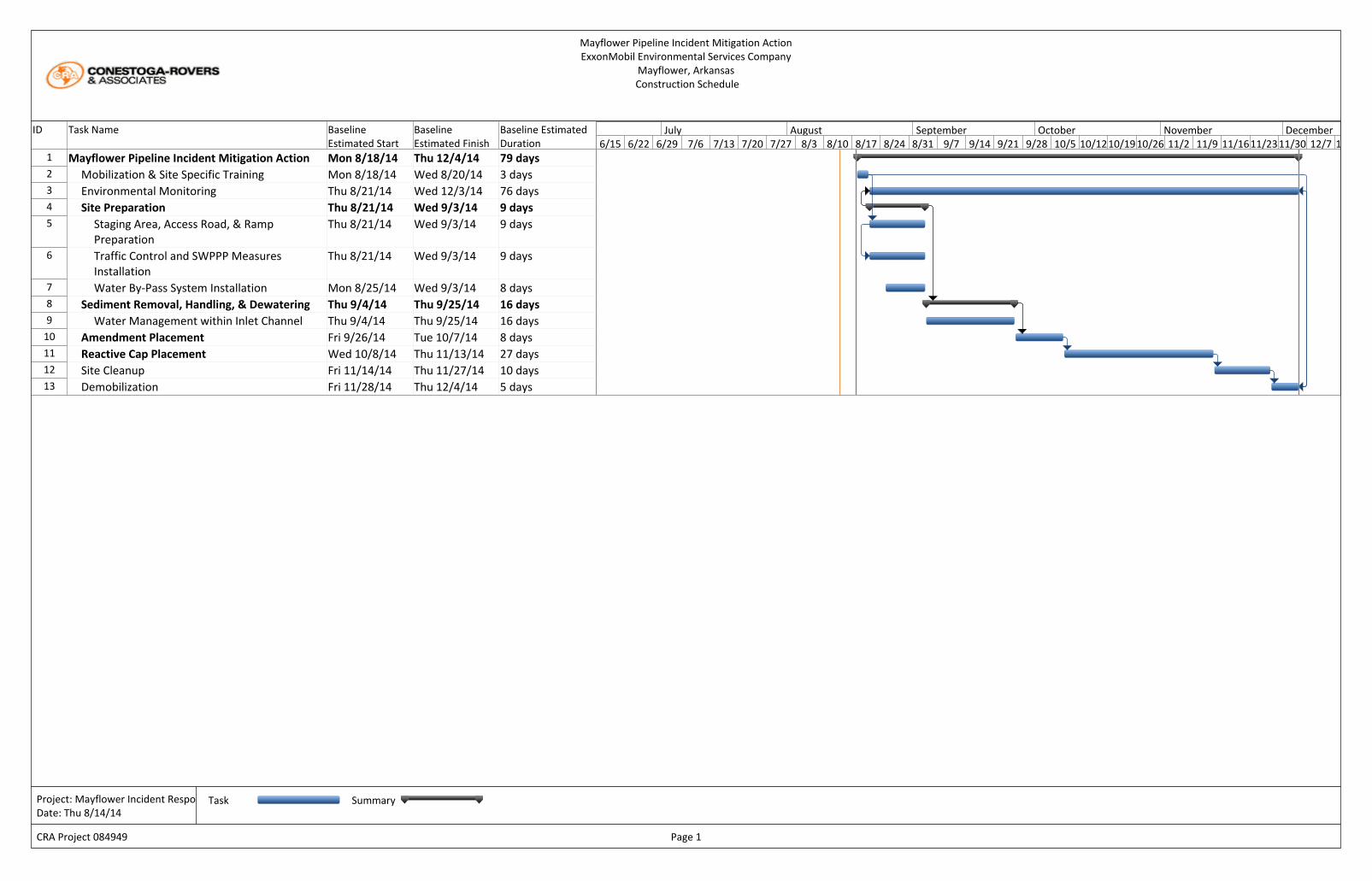
The start for mobilization, training and site preparation is August 18, 2014 (Appendix D). Construction activities are anticipated to start at the beginning of September 2014, contingent

ExxonMobil Environmental Services Company Mayflower Pipeline Incident Response Mitigation Action Construction Work Plan
084949-98
August 2014 7
on permit approvals. CRA estimates a project duration of 108 calendar days, which includes 79 working days. Section 4.0 References
ARCADIS. 2014. Mitigation Action Plan. Mayflower Pipeline Incident Response. Mayflower, Arkansas. Revision 1. June.
Copyright:© 2013 National Geographic Society, i-cubed
Arkansas
Site
Figure 1VICINITY MAP
MAYFLOWER CONSTRUCTION WORK PLANMAYFLOWER, ARKANSAS
ExxonMobil Environmental Services Company
0 2,0001,000Feet
NRE
: USG
S 7.5
Minu
te To
pogra
phic
Maps
.
8/14/2014
Site

[[
[[
[
[
[
[
[
[
[
[
[
[
[
[
[
[
[
[
[ [ [ [[ [ [ [
"$O"$O
Cove
LakeConway
"Rock" Staging Yard
"Chipper" Staging Yard
Main ConstructionEntrance/Exit
AlternateConstructionEntrance/Exit
Stormwater Inflowfrom City ofMayflower
Inlet Channel
Staging Area
Open WaterArea
Heavily VegetatedArea
SupportZone
Pump Pad
Diffusion Box
Sediment Solidification Box
Inlet Channel Crossing
Source: Esri, DigitalGlobe, GeoEye, i-cubed, Earthstar Geographics, CNES/Airbus DS, USDA, USGS, AEX, Getmapping, Aerogrid, IGN, IGP, swisstopo, andthe GIS User Community
Figure 2PLAN VIEW
MAYFLOWER CONSTRUCTION WORK PLANMAYFLOWER, ARKANSAS
ExxonMobil Environmental Services Company
RE: E
SRI 2
010 W
orld I
mage
ry.
84949-00(000)PR-BR006 8/14/2014
N
Legend"$O Straw Bales
Stormwater RunoffTemporary Water Diversion LineTemporary Mat RoadExisting Access RoadDrainage Path
[ [[ [ Silt CurtainContainment BoomDirection of Water FlowApproximate Water's EdgeApproximate Area to be DisturbedStaging YardsAreas with Heavy VegetationApproximate Limit of Work
0 300150Feet

ExxonMobil Environmental Services Company Mayflower Pipeline Incident Response Mitigation Action Construction Work Plan
084949-98 (3) August 2014
Appendix A
Stormwater Pollution & Prevention Plan
Revised date: 02/17/2012
Mayflower Pipeline Mayflower, Faulkner County, Arkansas
Stormwater Pollution Prevention Plan (SWPPP) for Construction Activity
National Pollutant Discharge Elimination System (NPDES) General Permit # ARR150000
Prepared for: Conestoga-Rovers & Associates
Date: August 2014
Prepared by: Alex Byrum
Stormwater Pollution Prevention Plan for Construction Activity Page 1 ARR150000
Revised date: 02/17/2012
Project Name and Location: Mayflower Pipeline, Mayflower, Faulkner County, Arkansas
Property Parcel Number (Optional):
Operator Name and Address: Conestoga-Rovers & Associates, 11719 Hinson Rd, Little Rock, AR
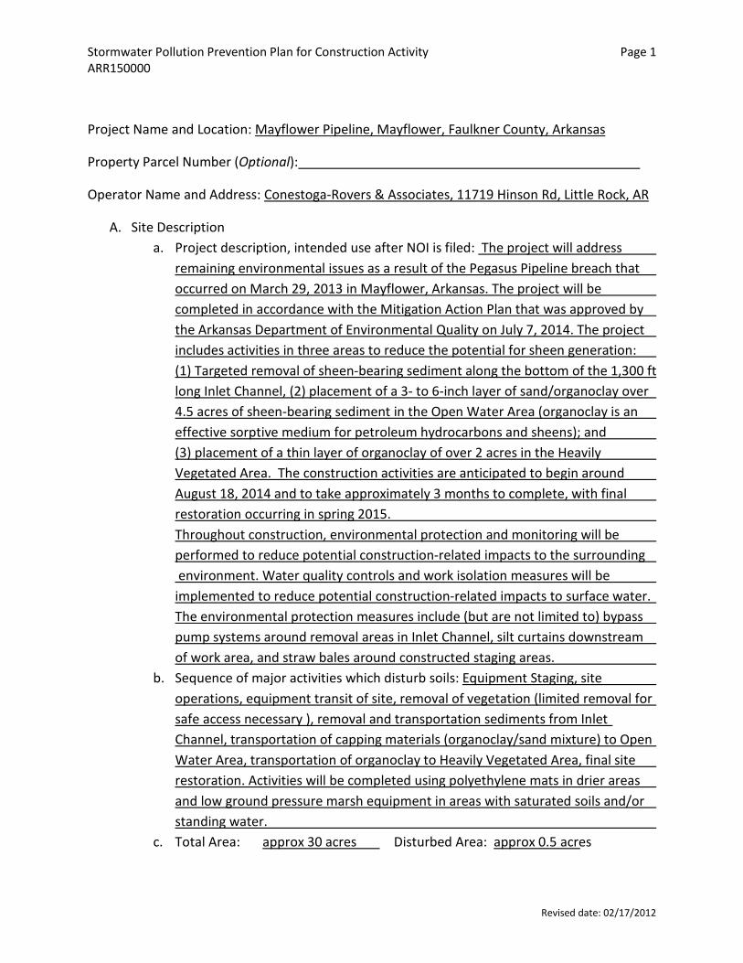
A. Site Description a. Project description, intended use after NOI is filed: The project will address
remaining environmental issues as a result of the Pegasus Pipeline breach that occurred on March 29, 2013 in Mayflower, Arkansas. The project will be completed in accordance with the Mitigation Action Plan that was approved by the Arkansas Department of Environmental Quality on July 7, 2014. The project includes activities in three areas to reduce the potential for sheen generation: (1) Targeted removal of sheen-bearing sediment along the bottom of the 1,300 ft long Inlet Channel, (2) placement of a 3- to 6-inch layer of sand/organoclay over 4.5 acres of sheen-bearing sediment in the Open Water Area (organoclay is an effective sorptive medium for petroleum hydrocarbons and sheens); and (3) placement of a thin layer of organoclay of over 2 acres in the Heavily Vegetated Area. The construction activities are anticipated to begin around August 18, 2014 and to take approximately 3 months to complete, with final restoration occurring in spring 2015. Throughout construction, environmental protection and monitoring will be performed to reduce potential construction-related impacts to the surrounding environment. Water quality controls and work isolation measures will be implemented to reduce potential construction-related impacts to surface water. The environmental protection measures include (but are not limited to) bypass pump systems around removal areas in Inlet Channel, silt curtains downstream of work area, and straw bales around constructed staging areas.
b. Sequence of major activities which disturb soils: Equipment Staging, site operations, equipment transit of site, removal of vegetation (limited removal for safe access necessary ), removal and transportation sediments from Inlet Channel, transportation of capping materials (organoclay/sand mixture) to Open Water Area, transportation of organoclay to Heavily Vegetated Area, final site restoration. Activities will be completed using polyethylene mats in drier areas and low ground pressure marsh equipment in areas with saturated soils and/or standing water.
c. Total Area: approx 30 acres Disturbed Area: approx 0.5 acres
Stormwater Pollution Prevention Plan for Construction Activity Page 2 ARR150000
Revised date: 02/17/2012
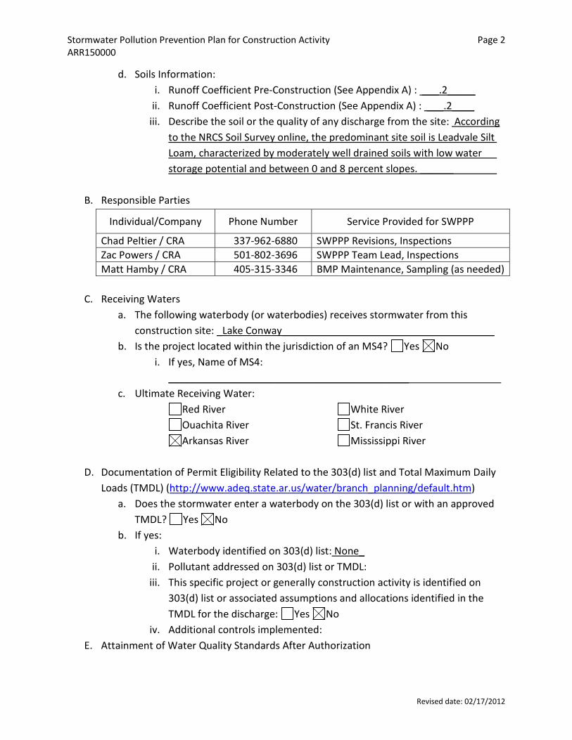
d. Soils Information: i. Runoff Coefficient Pre-Construction (See Appendix A) : ___.2_____
ii. Runoff Coefficient Post-Construction (See Appendix A) : ___.2____ iii. Describe the soil or the quality of any discharge from the site: According
to the NRCS Soil Survey online, the predominant site soil is Leadvale Silt Loam, characterized by moderately well drained soils with low water storage potential and between 0 and 8 percent slopes. ______
B. Responsible Parties
Individual/Company Phone Number Service Provided for SWPPP
Chad Peltier / CRA 337-962-6880 SWPPP Revisions, Inspections Zac Powers / CRA 501-802-3696 SWPPP Team Lead, Inspections Matt Hamby / CRA 405-315-3346 BMP Maintenance, Sampling (as needed)
C. Receiving Waters a. The following waterbody (or waterbodies) receives stormwater from this
construction site: _Lake Conway______________________________________ b. Is the project located within the jurisdiction of an MS4? Yes No
i. If yes, Name of MS4: ___________________________________________
c. Ultimate Receiving Water: Red River Ouachita River Arkansas River
White River St. Francis River Mississippi River
D. Documentation of Permit Eligibility Related to the 303(d) list and Total Maximum Daily
Loads (TMDL) (http://www.adeq.state.ar.us/water/branch_planning/default.htm) a. Does the stormwater enter a waterbody on the 303(d) list or with an approved
TMDL? Yes No b. If yes:
i. Waterbody identified on 303(d) list: None_ ii. Pollutant addressed on 303(d) list or TMDL:
iii. This specific project or generally construction activity is identified on 303(d) list or associated assumptions and allocations identified in the TMDL for the discharge: Yes No
iv. Additional controls implemented: E. Attainment of Water Quality Standards After Authorization

Stormwater Pollution Prevention Plan for Construction Activity Page 2 ARR150000
Revised date: 02/17/2012
a. The permittee must select, install, implement, and maintain BMPs at the construction site that minimize pollutants in the discharge as necessary to meet applicable water quality standards. In general, except in situations explained below, the SWPPP developed, implemented, and updated to be considered as stringent as necessary to ensure that the discharges do not cause or contribute to an excursion above any applicable water quality standard.
b. At any time after authorization, the Department may determine that the stormwater discharges may cause, have reasonable potential to cause, or contribute to an excursion above any applicable water quality standard. If such a determination is made, the Department will require the permittee to:
i. Develop a supplemental BMP action plan describing SWPPP modifications to address adequately the identified water quality concerns and submit valid and verifiable data and information that are representative of ambient conditions and indicate that the receiving water is attaining water quality standards; or
ii. Cease discharges of pollutants from construction activity and submit an individual permit application.
I understand and agree to follow the above text regarding the attainment of water quality standards after authorization. Yes No
F. Site Map Requirements (Attach Site Map): a. Pre-construction topographic view; - N/A, no grading or change in topography b. Direction of stormwater flow (i.e., use arrows to show which direction
stormwater will flow) and approximate slopes anticipated after grading activities;
c. Delineate on the site map areas of soil disturbance and areas that will not be disturbed under the coverage of this permit;
d. Location of major structural and nonstructural controls identified in the plan; e. Location of main construction entrance and exit; f. Location where stabilization practices are expected to occur; g. Locations of off-site materials, waste, borrow area, or equipment storage area; h. Location of areas used for concrete wash-out; - N/A i. Location of all surface water bodies (including wetlands); j. Locations where stormwater is discharged to a surface water and/or municipal
separate storm sewer system if applicable; k. Locations where stormwater is discharged off-site (should be continuously
updated);
Stormwater Pollution Prevention Plan for Construction Activity Page 3 ARR150000
Revised date: 02/17/2012
l. Areas where final stabilization has been accomplished and no further construction phase permit requirements apply.
G. Stormwater Controls
a. Initial Site Stabilization, Erosion and Sediment Controls, and Best Management Practices:
i. Initial Site Stabilization: The site staging yards and access roads will be the primary locations of storm water mitigation. The staging yards have been constructed with crushed stone and wooden board mats to support vehicles and equipment. The remainder of the site is in a cove of Lake Conway and is inundated during normal conditions.
ii. Erosion and Sediment Controls: Care will be taken to control runoff and silt from migrating from the work areas. Straw bales will be used in the two site staging yards, the “Chipper” staging yard and the “Rock” staging yard to control runoff from storm water. If runoff is too high, operations will be suspended until conditions improve.
iii. If periodic inspections or other information indicates a control has been used inappropriately or incorrectly, the operator will replace or modify the control for site situations: Yes No
If No, explain: ______________________________________________________
iv. Off-site accumulations of sediment will be removed at a frequency sufficient to minimize off-site impacts: Yes No
If No, explain: _______________________________________________________
v. Sediment will be removed from sediment traps or sedimentation ponds when design capacity has been reduced by 50%: Yes No
If No, explain: It is not anticipated that sediment traps or ponds will be used on-site for storm water control because the area is located in a cove. If sediment from site operations builds up in naturally low lying areas, the sediment will be removed on an as-needed basis.
Stormwater Pollution Prevention Plan for Construction Activity Page 4 ARR150000
Revised date: 02/17/2012
vi. Litter, construction debris, and construction chemicals exposed to stormwater shall be prevented from becoming a pollutant source for stormwater discharges: Yes No
If No, explain: ________________________________________________________
vii. Off-site material storage areas used solely by the permitted project are being covered by this SWPPP: Yes No
If Yes, explain additional BMPs implemented at off-site material storage area: _______________________________________________________ _
b. Stabilization Practices i. Description and Schedule: _Erosion control blankets will be used on the
exposed portions of the reactive cap areas. ____
ii. Are buffer areas required? Yes No If Yes, are buffer areas being used? Yes No
If No, explain why not: Buffer areas are not required during the construction activities, which are limited to the area within the cove and inlet
If Yes, describe natural buffer areas: ________________________________________________________
iii. A record of the dates when grading activities occur, when construction activities temporarily or permanently cease on a portion of the site, and when stabilization measures are initiated shall be included with the plan.
Yes No If No, explain: ______________________________________________________ _
iv. Deadlines for stabilization: Stabilization procedures will be initiated 14 days after construction activity temporarily ceases on a portion of the site.
c. Structural Practices i. Describe any structural practices to divert flows from exposed soils, store
flows, or otherwise limit runoff and the discharge of pollutants from exposed areas of the site: Straw bales will be placed in areas of where
Stormwater Pollution Prevention Plan for Construction Activity Page 5 ARR150000
Revised date: 02/17/2012
runoff leaves the operational yards to slow the migration of storm water and silt from these areas. Storm water at the site will primarily infiltrate the site soils prior to entering the cove into Lake Conway.
ii. Sediment Basins: Are 10 or more acres draining to a common point? Yes No Is a sediment basin included in the project? Yes No
If Yes, what is the designed capacity for the storage? 3600 cubic feet per acre = : _____________________________
or 10 year, 24 hour storm = _______________________________ Other criteria were used to design basin: _______ __ _____
If No, explain why no sedimentation basin was included and describe required natural buffer areas and other controls implemented instead: Natural buffers will be used along with site topography. A small percentage of the overall site area is located up gradient from the cove and operational areas. These areas are small enough to be managed using straw bales.__
iii. Describe Velocity Dissipation Devices: Straw bales in drainage pathways to slow storm water runoff where applicable._______
H. Other Controls a. Solid materials, including building materials, shall be prevented from being
discharged to Waters of the State: Yes No b. Off-site vehicle tracking of sediments and the generation of dust shall be
minimized through the use of: A stabilized construction entrance and exit Vehicle tire washing Other controls, describe: _Tracked vehicles will be cleaned prior to
demobilization from the site. c. Temporary Sanitary Facilities: Multiple portable toilets will be placed on-site in
both operational staging yards. These will be maintained as needed throughout the project at a minimum of once per week.
d. Concrete Waste Area Provided: Yes No. Concrete is used on the site, but no concrete washout is provided.
Explain why: N/A, no concrete will be used with this project
Stormwater Pollution Prevention Plan for Construction Activity Page 6 ARR150000
Revised date: 02/17/2012
e. Fuel Storage Areas, Hazardous Waste Storage, and Truck Wash Areas: Hazardous wastes are not stored on-site. Fueling done on-site is currently accomplished in two ways: mobile fueling using an auxiliary fuel tank attached to a flatbed truck for smaller equipment. The other way is one, 1,000 gallon fuel tank located in the Rock Yard staging area. This fuel tank is UL approved will be either a double-walled steel tank or will have secondary containment. A spill kit, including sorbent materials and cleanup tools is located at the dispensing end of this tank. A bucket and absorbent pads will be used routinely to prevent small spills and drips from the dispensing nozzle. All fueling will take place at one of the operational yards or staging areas to minimize potential impacts to water in the cove area. The fixed 1,000 gallon fuel tank will be filled periodically by an outside contracted service. The tank will only be filled when operational personnel are present. The tank truck operator will be outside the cab of the tank truck and present during the entire filling process. A spill kit and buckets will be used to minimize spills and drips during filling. Hazardous waste generation is not anticipated on-site. If hazardous waste is generated, it will be stored so as not to contact storm water and managed according to federal and state regulations prior to off-site disposal. Truck/equipment decontamination and washing will be done adjacent to the operational area. Wash water will be monitored for sheen and nuisance materials. All sheen and nuisance materials will be removed from the wash water as soon as possible by the equipment decontamination teams. This will be accomplished using absorbent pads and materials. These pads and materials will be managed and stored to minimize contact with water and storm water after use.
I. Non-Stormwater Discharges a. The following allowable non-stormwater discharges comingled with stormwater
are present or anticipated at the site:
Fire-fighting activities;
Fire hydrant flushings;
Water used to wash/decontaminate equipment and vehicles (where detergents or other chemicals are not used) or control dust in accordance with Part II.A.4.H.2;
Potable water sources including uncontaminated waterline flushings;
Landscape Irrigation;
Stormwater Pollution Prevention Plan for Construction Activity Page 7 ARR150000
Revised date: 02/17/2012
Routine external building wash down which does not use detergents or other chemicals;
Pavement wash waters where spills or leaks of toxic or hazardous materials have not occurred (unless all spilled materials have been removed) and where detergents or other chemicals are not used;
Uncontaminated air conditioning, compressor condensate (See Part I.B.12.C of the permit);
Uncontaminated springs, excavation dewatering and groundwater (See Part I.B.12.C of the permit);
Foundation or footing drains where flows are not contaminated with process materials such as solvents (See Part I.B.12.C of the permit);
b. Describe any controls associated with non-stormwater discharges present at the site: _Any non-storm water discharges will be monitored for the presence of oils and other nuisance materials. These will be removed using sorbent materials as soon as possible to lessen the risk of storm water or other means causing migration to the cove area. Decontamination water will be monitored during equipment and vehicle decontamination operations and all sheens and nuisance materials will be removed from the decontamination water to ensure that the oil does not flow into the cove area. A bypass pump will be used to divert water around operational areas. A diffuser will be used and all diverted water will be discharged inside sorbent boom to control sediment and any sheen from upstream water flow.
J. Post-Construction Stormwater Management:
Describe measures installed during the construction process to control pollutants in stormwater discharges that will occur after construction operations have been completed: _Site restoration activities will include replanting vegetation, repairing roads and vehicle access areas back to grade and removal of all temporary structures. ___________________________________________
K. Applicable State or Local Programs: The SWPPP will be updated as necessary to reflect any revisions to applicable federal, state, or local requirements that affect the stormwater controls implemented at the site. Yes No
L. Inspections
a. Inspection frequency: Every 7 calendar days
Stormwater Pollution Prevention Plan for Construction Activity Page 8 ARR150000
Revised date: 02/17/2012
or At least once every 14 calendar days and within 24 hours of the end of a
storm even 0.5 inches or greater (a rain gauge must be maintained on-site) b. Inspections:
Completed inspection forms will be kept with the SWPPP. ADEQ’s inspection form will be used (See Appendix B)
or A form other than ADEQ’s inspection form will be used and is attached
(See inspection form requirements Part II.A.4.L.2) c. Inspection records will be retained as part of the SWPPP for at least 3 years from
the date of termination. d. It is understood that the following sections describe waivers of site inspection
requirements. All applicable documentation requirements will be followed in accordance with the referenced sections.
i. Winter Conditions (Part II.A.4.L.3) ii. Adverse Weather Conditions (Part II.A.4.L.4)
M. Maintenance:
The following procedures to maintain vegetation, erosion and sediment control measures and other protective measures in good, effective operating condition will be followed: _Inspections will be conducted. Protective measures found to be in need to maintenance or repair will be noted and repaired within 3 business days as stated below. Care will be taken to maintain current vegetation and to minimize erosion by utilizing the currently in-place roads and not creating additional ingress/egress pathways. Polyethylene mats will be placed in the ingress/egress pathways to minimize soil erosion_______________________________________ Any necessary repairs will be completed, when practicable, before the next storm event, but not to exceed a period of 3 business days of discovery, or as otherwise directed by state or local officials.
N. Employee Training: The following is a description of the training plan for personnel (including contractors and subcontractors) on this project: _All site workers will be familiar with this SWPPP, including its location on the site, the Best Management Practices, and the various methods for recognizing, reporting and maintaining storm water management on-site. Periodically BMPs will be presented to site workers during the all-hands safety meetings prior to the beginning of operational periods. Site workers
Stormwater Pollution Prevention Plan for Construction Activity Page 9 ARR150000
Revised date: 02/17/2012
named in this plan will be specifically trained on carrying out the storm water management at the site, including implementation of BMPs, inspections and documentation as necessary. **Note, Formal training classes given by Universities or other third-party organizations are not required, but recommended for qualified trainers; the permittee is responsible for the content of the training being adequate for personnel to implement the requirements of the permit.
Certification
"I certify under penalty of law that this document and all attachments such as Inspection Form were prepared under my direction or supervision in accordance with a system designed to ensure that qualified personnel properly gather and evaluate the information submitted. Based on my inquiry of the person or persons who manage the system, or those persons directly responsible for gathering the information, the information submitted is, to the best of my knowledge and belief, true, accurate, and complete. I am aware that there are significant penalties for submitting false information, including the possibility of fine and imprisonment for knowing violations." Signature of Responsible or Cognizant Official: Title: __________________________ Date:
Computation Sheet for Determining Runoff Coefficients Appendix A
Revised date: 02/17/2012
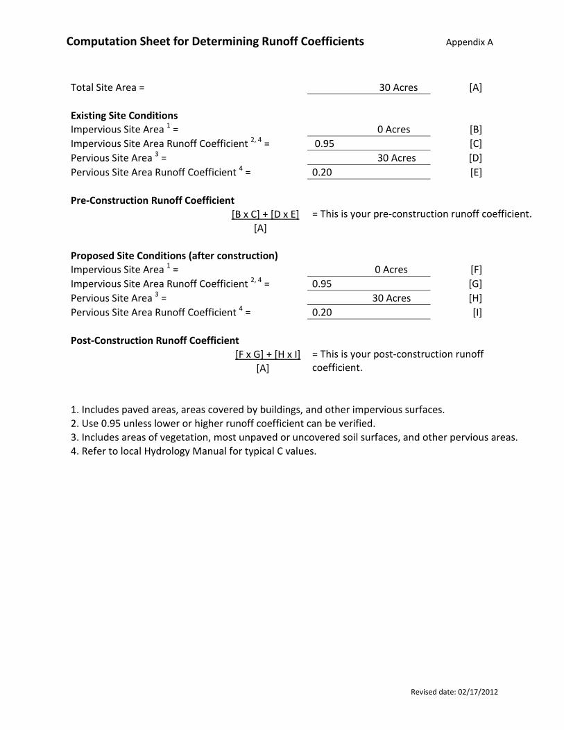
Total Site Area = 30 Acres [A]
Existing Site Conditions
Impervious Site Area 1 = 0 Acres [B] Impervious Site Area Runoff Coefficient 2, 4 = 0.95 [C] Pervious Site Area 3 = 30 Acres [D] Pervious Site Area Runoff Coefficient 4 = 0.20 [E]
Pre-Construction Runoff Coefficient [B x C] + [D x E] = This is your pre-construction runoff coefficient.
[A]
Proposed Site Conditions (after construction) Impervious Site Area 1 = 0 Acres [F]
Impervious Site Area Runoff Coefficient 2, 4 = 0.95 [G] Pervious Site Area 3 = 30 Acres [H] Pervious Site Area Runoff Coefficient 4 = 0.20 [I]
Post-Construction Runoff Coefficient [F x G] + [H x I] = This is your post-construction runoff coefficient. [A]
1. Includes paved areas, areas covered by buildings, and other impervious surfaces. 2. Use 0.95 unless lower or higher runoff coefficient can be verified. 3. Includes areas of vegetation, most unpaved or uncovered soil surfaces, and other pervious areas. 4. Refer to local Hydrology Manual for typical C values.
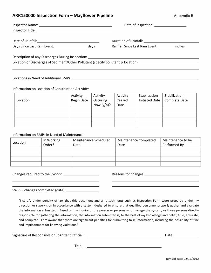
ARR150000 Inspection Form – Mayflower Pipeline Appendix B
Revised date: 02/17/2012
Inspector Name: Date of Inspection: Inspector Title: Date of Rainfall: Duration of Rainfall: Days Since Last Rain Event: days Rainfall Since Last Rain Event: inches Description of any Discharges During Inspection: Location of Discharges of Sediment/Other Pollutant (specify pollutant & location): Locations in Need of Additional BMPs: Information on Location of Construction Activities
Information on BMPs in Need of Maintenance
Location In Working Order?
Maintenance Scheduled Date
Maintenance Completed Date
Maintenance to be Performed By
Changes required to the SWPPP:
Reasons for changes:
SWPPP changes completed (date): "I certify under penalty of law that this document and all attachments such as Inspection Form were prepared under my direction or supervision in accordance with a system designed to ensure that qualified personnel properly gather and evaluate the information submitted. Based on my inquiry of the person or persons who manage the system, or those persons directly responsible for gathering the information, the information submitted is, to the best of my knowledge and belief, true, accurate, and complete. I am aware that there are significant penalties for submitting false information, including the possibility of fine and imprisonment for knowing violations."
Signature of Responsible or Cognizant Official: Date:
Title:
Location Activity Begin Date
Activity Occuring Now (y/n)?
Activity Ceased Date
Stabilization Initiated Date
Stabilization Complete Date
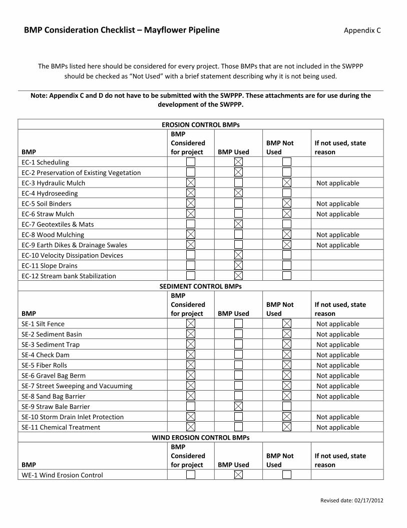
BMP Consideration Checklist – Mayflower Pipeline Appendix C
Revised date: 02/17/2012
The BMPs listed here should be considered for every project. Those BMPs that are not included in the SWPPP should be checked as “Not Used” with a brief statement describing why it is not being used.
Note: Appendix C and D do not have to be submitted with the SWPPP. These attachments are for use during the
development of the SWPPP.
EROSION CONTROL BMPs
BMP
BMP Considered for project BMP Used
BMP Not Used
If not used, state reason
EC-1 Scheduling EC-2 Preservation of Existing Vegetation EC-3 Hydraulic Mulch Not applicable EC-4 Hydroseeding
EC-5 Soil Binders Not applicable EC-6 Straw Mulch Not applicable EC-7 Geotextiles & Mats EC-8 Wood Mulching Not applicable EC-9 Earth Dikes & Drainage Swales Not applicable EC-10 Velocity Dissipation Devices EC-11 Slope Drains EC-12 Stream bank Stabilization
SEDIMENT CONTROL BMPs
BMP
BMP Considered for project BMP Used
BMP Not Used
If not used, state reason
SE-1 Silt Fence Not applicable SE-2 Sediment Basin Not applicable SE-3 Sediment Trap Not applicable SE-4 Check Dam Not applicable SE-5 Fiber Rolls Not applicable SE-6 Gravel Bag Berm Not applicable SE-7 Street Sweeping and Vacuuming Not applicable SE-8 Sand Bag Barrier Not applicable SE-9 Straw Bale Barrier SE-10 Storm Drain Inlet Protection Not applicable SE-11 Chemical Treatment Not applicable
WIND EROSION CONTROL BMPs
BMP
BMP Considered for project BMP Used
BMP Not Used
If not used, state reason
WE-1 Wind Erosion Control
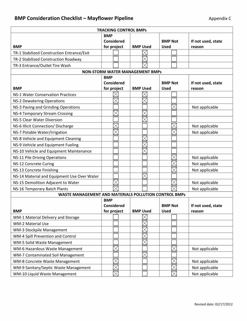
BMP Consideration Checklist – Mayflower Pipeline Appendix C
Revised date: 02/17/2012
TRACKING CONTROL BMPs
BMP
BMP Considered for project BMP Used
BMP Not Used
If not used, state reason
TR-1 Stabilized Construction Entrance/Exit TR-2 Stabilized Construction Roadway TR-3 Entrance/Outlet Tire Wash
NON-STORM WATER MANAGEMENT BMPs
BMP
BMP Considered for project BMP Used
BMP Not Used
If not used, state reason
NS-1 Water Conservation Practices NS-2 Dewatering Operations NS-3 Paving and Grinding Operations Not applicable NS-4 Temporary Stream Crossing NS-5 Clear Water Diversion NS-6 Illicit Connection/ Discharge Not applicable NS-7 Potable Water/Irrigation Not applicable NS-8 Vehicle and Equipment Cleaning NS-9 Vehicle and Equipment Fueling NS-10 Vehicle and Equipment Maintenance NS-11 Pile Driving Operations Not applicable NS-12 Concrete Curing Not applicable NS-13 Concrete Finishing Not applicable NS-14 Material and Equipment Use Over Water NS-15 Demolition Adjacent to Water Not applicable NS-16 Temporary Batch Plants Not applicable
WASTE MANAGEMENT AND MATERIALS POLLUTION CONTROL BMPs
BMP
BMP Considered for project BMP Used
BMP Not Used
If not used, state reason
WM-1 Material Delivery and Storage WM-2 Material Use WM-3 Stockpile Management WM-4 Spill Prevention and Control WM-5 Solid Waste Management WM-6 Hazardous Waste Management Not applicable WM-7 Contaminated Soil Management WM-8 Concrete Waste Management Not applicable WM-9 Sanitary/Septic Waste Management Not applicable WM-10 Liquid Waste Management Not applicable
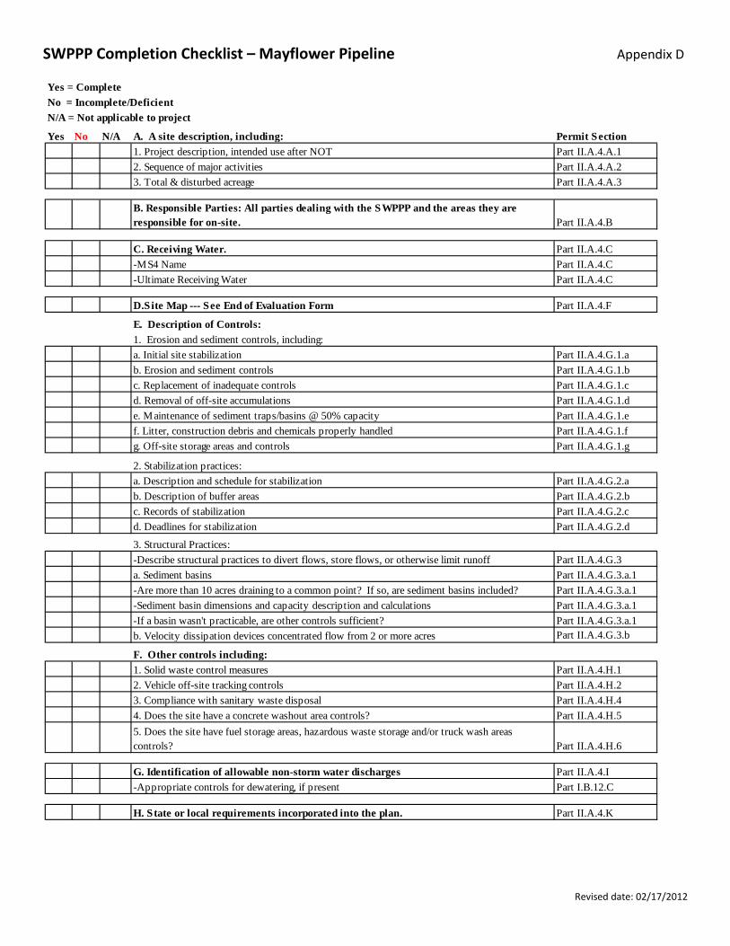
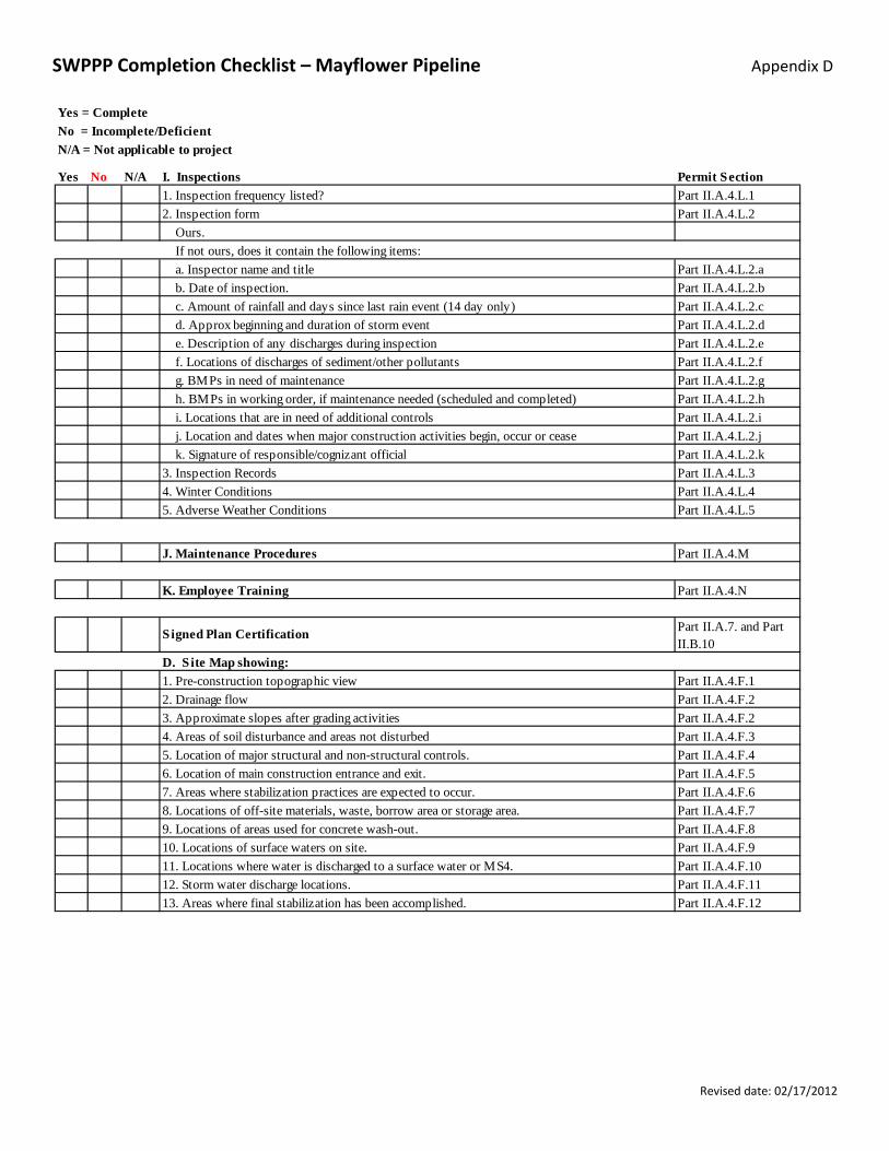
SWPPP Completion Checklist – Mayflower Pipeline Appendix D
Revised date: 02/17/2012
Yes No N/A Permit SectionPart II.A.4.A.1Part II.A.4.A.2Part II.A.4.A.3
Part II.A.4.B
Part II.A.4.CPart II.A.4.CPart II.A.4.C
Part II.A.4.F
Part II.A.4.G.1.aPart II.A.4.G.1.bPart II.A.4.G.1.cPart II.A.4.G.1.dPart II.A.4.G.1.ePart II.A.4.G.1.fPart II.A.4.G.1.g
Part II.A.4.G.2.aPart II.A.4.G.2.bPart II.A.4.G.2.cPart II.A.4.G.2.d
Part II.A.4.G.3Part II.A.4.G.3.a.1Part II.A.4.G.3.a.1Part II.A.4.G.3.a.1Part II.A.4.G.3.a.1Part II.A.4.G.3.b
Part II.A.4.H.1Part II.A.4.H.2Part II.A.4.H.4Part II.A.4.H.5
Part II.A.4.H.6
Part II.A.4.IPart I.B.12.C
Part II.A.4.K
e. Maintenance of sediment traps/basins @ 50% capacity
-If a basin wasn't practicable, are other controls sufficient?-Sediment basin dimensions and capacity description and calculations
b. Description of buffer areasc. Records of stabilization
3. Structural Practices:
-Are more than 10 acres draining to a common point? If so, are sediment basins included?
d. Deadlines for stabilization
c. Replacement of inadequate controlsd. Removal of off-site accumulations
g. Off-site storage areas and controls
2. Stabilization practices:a. Description and schedule for stabilization
a. Sediment basins
3. Total & disturbed acreage
-MS4 Name-Ultimate Receiving Water
b. Erosion and sediment controls
G. Identification of allowable non-storm water discharges
H. State or local requirements incorporated into the plan.
3. Compliance with sanitary waste disposal
5. Does the site have fuel storage areas, hazardous waste storage and/or truck wash areas controls?
4. Does the site have a concrete washout area controls?
-Appropriate controls for dewatering, if present
E. Description of Controls:1. Erosion and sediment controls, including:a. Initial site stabilization
Yes = CompleteNo = Incomplete/DeficientN/A = Not applicable to project
1. Project description, intended use after NOTA. A site description, including:
B. Responsible Parties: All parties dealing with the SWPPP and the areas they are responsible for on-site.
C. Receiving Water.
D.Site Map --- See End of Evaluation Form
2. Sequence of major activities
2. Vehicle off-site tracking controls
b. Velocity dissipation devices concentrated flow from 2 or more acres
1. Solid waste control measures
-Describe structural practices to divert flows, store flows, or otherwise limit runoff
f. Litter, construction debris and chemicals properly handled
F. Other controls including:
SWPPP Completion Checklist – Mayflower Pipeline Appendix D
Revised date: 02/17/2012
Yes No N/A Permit SectionPart II.A.4.L.1Part II.A.4.L.2
If not ours, does it contain the following items:Part II.A.4.L.2.aPart II.A.4.L.2.bPart II.A.4.L.2.cPart II.A.4.L.2.dPart II.A.4.L.2.ePart II.A.4.L.2.fPart II.A.4.L.2.gPart II.A.4.L.2.hPart II.A.4.L.2.iPart II.A.4.L.2.jPart II.A.4.L.2.kPart II.A.4.L.3Part II.A.4.L.4Part II.A.4.L.5
Part II.A.4.M
Part II.A.4.N
Part II.A.7. and Part II.B.10
Part II.A.4.F.1Part II.A.4.F.2Part II.A.4.F.2Part II.A.4.F.3Part II.A.4.F.4Part II.A.4.F.5Part II.A.4.F.6Part II.A.4.F.7Part II.A.4.F.8Part II.A.4.F.9Part II.A.4.F.10Part II.A.4.F.11Part II.A.4.F.12
12. Storm water discharge locations.13. Areas where final stabilization has been accomplished.
6. Location of main construction entrance and exit.
I. Inspections
d. Approx beginning and duration of storm event e. Description of any discharges during inspection f. Locations of discharges of sediment/other pollutants
i. Locations that are in need of additional controls
Signed Plan Certification
10. Locations of surface waters on site.
K. Employee Training
h. BMPs in working order, if maintenance needed (scheduled and completed)
a. Inspector name and title b. Date of inspection.
9. Locations of areas used for concrete wash-out.
11. Locations where water is discharged to a surface water or MS4.
8. Locations of off-site materials, waste, borrow area or storage area.
5. Location of major structural and non-structural controls.
4. Winter Conditions
2. Drainage flow3. Approximate slopes after grading activities
D. S ite Map showing:1. Pre-construction topographic view
7. Areas where stabilization practices are expected to occur.
4. Areas of soil disturbance and areas not disturbed
c. Amount of rainfall and days since last rain event (14 day only)
g. BMPs in need of maintenance
N/A = Not applicable to project
5. Adverse Weather Conditions
Yes = Complete
J. Maintenance Procedures
No = Incomplete/Deficient
1. Inspection frequency listed?2. Inspection form Ours.
3. Inspection Records k. Signature of responsible/cognizant official j. Location and dates when major construction activities begin, occur or cease

[[
[[
[
[
[
[
[
[
[
[
[
[
[
[
[
[
[
[
[ [ [ [[ [ [ [
"$O"$O
Cove
LakeConway
"Rock" Staging Yard
"Chipper" Staging Yard
Main ConstructionEntrance/Exit
AlternateConstructionEntrance/Exit
Stormwater Inflowfrom City ofMayflower
Inlet Channel
Staging Area
Open WaterArea
Heavily VegetatedArea
SupportZone
Pump Pad
DiffusionBox
Source: Esri, DigitalGlobe, GeoEye, i-cubed, Earthstar Geographics, CNES/Airbus DS, USDA, USGS, AEX, Getmapping, Aerogrid, IGN, IGP, swisstopo, andthe GIS User Community
Figure 1SWPPP SITE MAP
MAYFLOWER COVE CONSTRUCTIONMAYFLOWER, ARKANSAS
ExxonMobil Environmental Services Company
RE:
ESR
I 201
0 W
orld
Imag
ery.
84949-00(000)PR-BR003 8/6/2014
N
Legend"$O Hay Bales
Stormwater RunoffTemporary Water Diversion LineTemporary Mat RoadExisting Access RoadDrainage Path
[ [[ [ Silt CurtainContainment BoomDirection of Water FlowApproximate Water's EdgeApproximate Area to be DisturbedStaging YardsAreas with Heavy VegetationApproximate Limit of Work
0 300150Feet

ExxonMobil Environmental Services Company Mayflower Pipeline Incident Response
Mitigation Action Construction Work Plan
084949-98 (4) August 2014
Appendix .
Site Security Plan
084949-98 (4) APP B B- 1
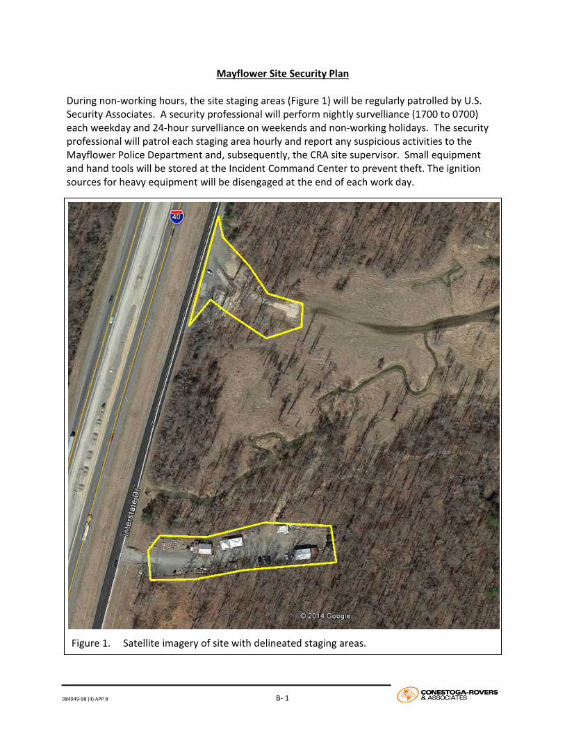
Mayflower Site Security Plan During non-working hours, the site staging areas (Figure 1) will be regularly patrolled by U.S. Security Associates. A security professional will perform nightly survelliance (1700 to 0700) each weekday and 24-hour survelliance on weekends and non-working holidays. The security professional will patrol each staging area hourly and report any suspicious activities to the Mayflower Police Department and, subsequently, the CRA site supervisor. Small equipment and hand tools will be stored at the Incident Command Center to prevent theft. The ignition sources for heavy equipment will be disengaged at the end of each work day.
Figure 1. Satellite imagery of site with delineated staging areas.

ExxonMobil Environmental Services Company Mayflower Pipeline Incident Response
Mitigation Action Construction Work Plan
084949-98 (4) August 2014
Appendix /
Traffic Control Plan

Conestoga-Rovers & Associates 5551 Corporate Blvd., Suite 200 Baton Rouge, Louisiana 70808
August 2014 ● 084949-98 (3) Appendix C
Appendix / Traffic Control Plan
Mayflower Pipeline Incident Response
Mayflower, Arkansas
Prepared for: ExxonMobil Environmental Services Company
ExxonMobil Environmental Services Company Traffic Control Plan
084949-98 (3) Appendix C
August 2014 1
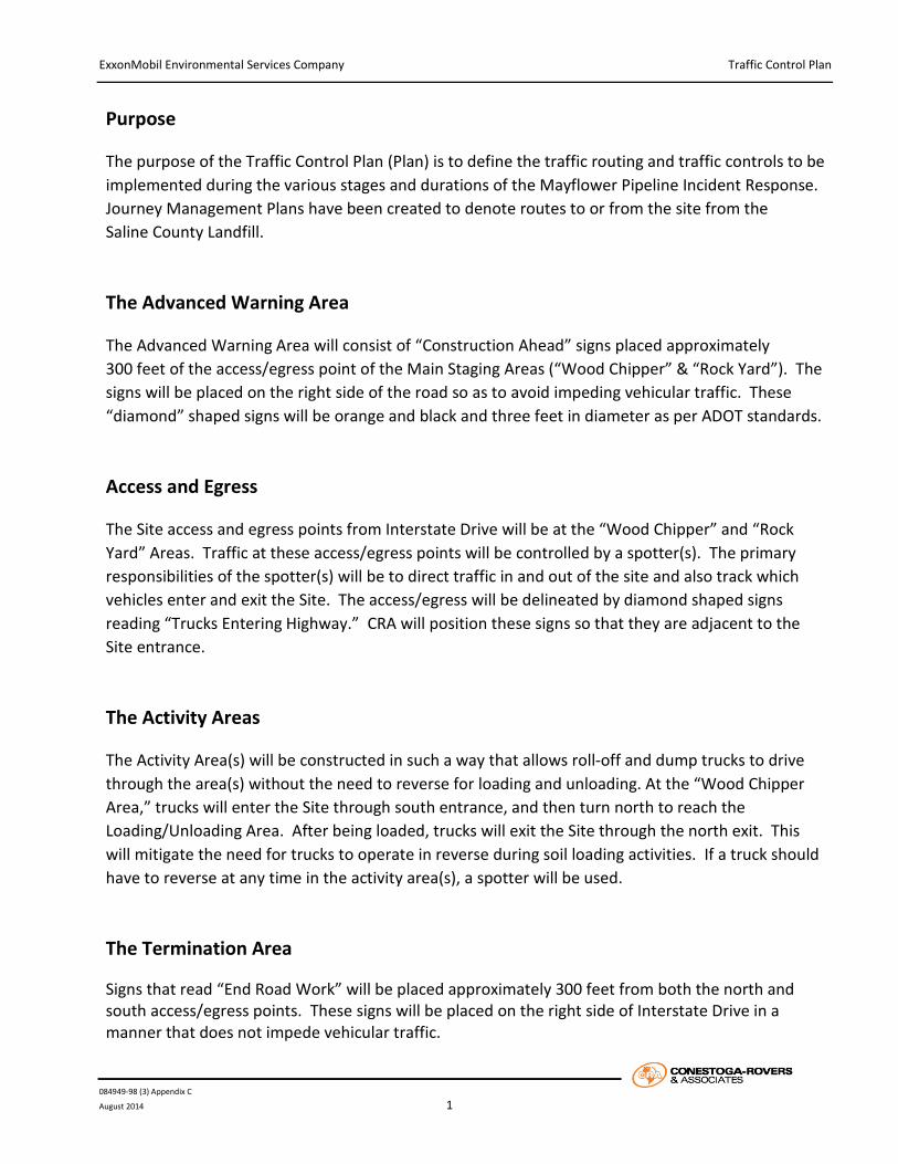
Purpose
The purpose of the Traffic Control Plan (Plan) is to define the traffic routing and traffic controls to be implemented during the various stages and durations of the Mayflower Pipeline Incident Response. Journey Management Plans have been created to denote routes to or from the site from the Saline County Landfill. The Advanced Warning Area
The Advanced Warning Area will consist of “Construction Ahead” signs placed approximately 300 feet of the access/egress point of the Main Staging Areas (“Wood Chipper” & “Rock Yard”). The signs will be placed on the right side of the road so as to avoid impeding vehicular traffic. These “diamond” shaped signs will be orange and black and three feet in diameter as per ADOT standards. Access and Egress
The Site access and egress points from Interstate Drive will be at the “Wood Chipper” and “Rock Yard” Areas. Traffic at these access/egress points will be controlled by a spotter(s). The primary responsibilities of the spotter(s) will be to direct traffic in and out of the site and also track which vehicles enter and exit the Site. The access/egress will be delineated by diamond shaped signs reading “Trucks Entering Highway.” CRA will position these signs so that they are adjacent to the Site entrance. The Activity Areas
The Activity Area(s) will be constructed in such a way that allows roll-off and dump trucks to drive through the area(s) without the need to reverse for loading and unloading. At the “Wood Chipper Area,” trucks will enter the Site through south entrance, and then turn north to reach the Loading/Unloading Area. After being loaded, trucks will exit the Site through the north exit. This will mitigate the need for trucks to operate in reverse during soil loading activities. If a truck should have to reverse at any time in the activity area(s), a spotter will be used. The Termination Area
Signs that read “End Road Work” will be placed approximately 300 feet from both the north and south access/egress points. These signs will be placed on the right side of Interstate Drive in a manner that does not impede vehicular traffic.
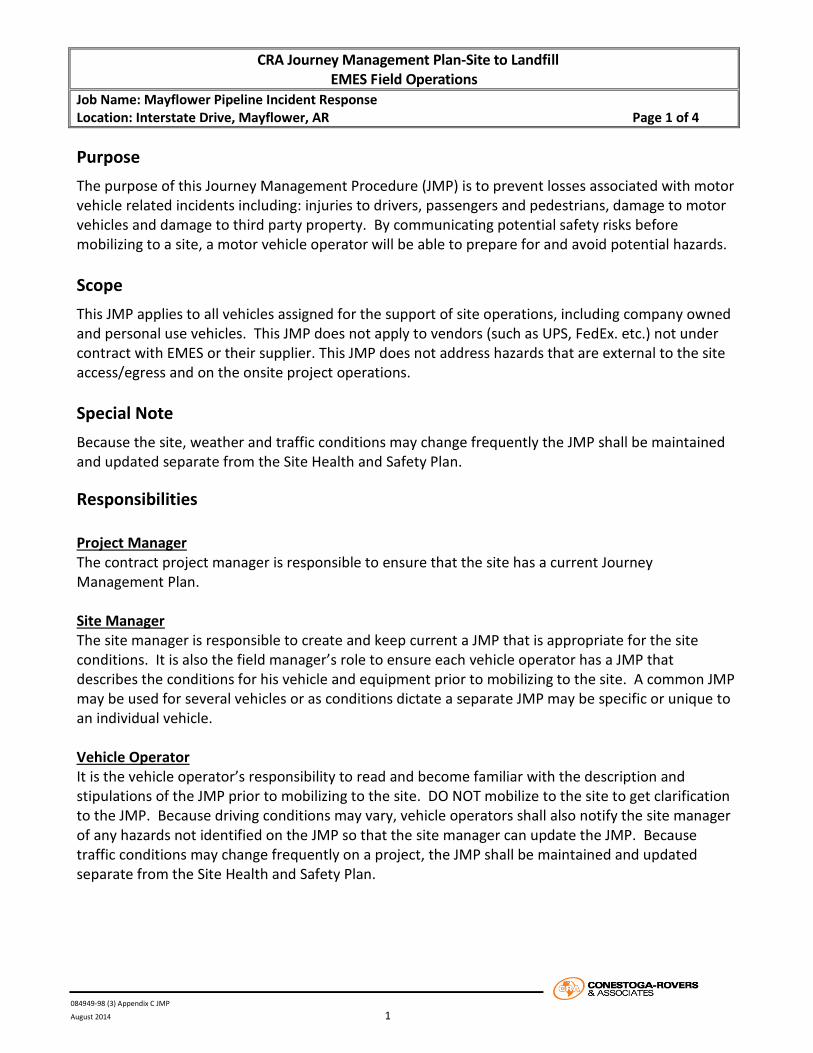
CRA Journey Management Plan-Site to Landfill EMES Field Operations
Job Name: Mayflower Pipeline Incident Response Location: Interstate Drive, Mayflower, AR Page 1 of 4
084949-98 (3) Appendix C JMP
August 2014 1
Purpose The purpose of this Journey Management Procedure (JMP) is to prevent losses associated with motor vehicle related incidents including: injuries to drivers, passengers and pedestrians, damage to motor vehicles and damage to third party property. By communicating potential safety risks before mobilizing to a site, a motor vehicle operator will be able to prepare for and avoid potential hazards. Scope This JMP applies to all vehicles assigned for the support of site operations, including company owned and personal use vehicles. This JMP does not apply to vendors (such as UPS, FedEx. etc.) not under contract with EMES or their supplier. This JMP does not address hazards that are external to the site access/egress and on the onsite project operations. Special Note Because the site, weather and traffic conditions may change frequently the JMP shall be maintained and updated separate from the Site Health and Safety Plan.
Responsibilities Project Manager The contract project manager is responsible to ensure that the site has a current Journey Management Plan. Site Manager The site manager is responsible to create and keep current a JMP that is appropriate for the site conditions. It is also the field manager’s role to ensure each vehicle operator has a JMP that describes the conditions for his vehicle and equipment prior to mobilizing to the site. A common JMP may be used for several vehicles or as conditions dictate a separate JMP may be specific or unique to an individual vehicle. Vehicle Operator It is the vehicle operator’s responsibility to read and become familiar with the description and stipulations of the JMP prior to mobilizing to the site. DO NOT mobilize to the site to get clarification to the JMP. Because driving conditions may vary, vehicle operators shall also notify the site manager of any hazards not identified on the JMP so that the site manager can update the JMP. Because traffic conditions may change frequently on a project, the JMP shall be maintained and updated separate from the Site Health and Safety Plan.
CRA Journey Management Plan-Site to Landfill EMES Field Operations
Job Name: Mayflower Pipeline Incident Response Location: Interstate Drive, Mayflower, AR Page 2 of 4
084949-98 (3) Appendix C JMP
August 2014 2
Scope of this JMP This JMP shall include the operation and use of the following vehicles and equipment: CRA’s trucks/vans, personal vehicles, drill rigs, and support equipment such as trailers, heavy equipment, etc. All vehicle operators shall be responsible for ensuring their vehicles are maintained and being familiar with and obeying all laws related to vehicle operation. The route to the Saline County Landfill from the Mayflower Site (see illustrations in this JMP): • Head North on Interstate Dr toward AR-89 W for 1 mile • Turn left onto AR-89 W for 0.2 miles • Turn left onto I-40 E toward Little Rock for 11.7 miles • Take exit 147 to merge onto I-430 S toward Texarkana for 12.8 miles • Take exit 129B to merge onto I-30 W toward Texarkana for 5.7 miles • Take exit 123 toward AR-183/Bryant/Bauxite for 0.2 miles • Merge onto I-30 Frontage Rd for 0.6 miles • Take the ramp to I-30 E for 0.2 miles • Merge onto N Reynolds Rd for 4.3 miles • Turn left onto W Sardis Rd for 1 mile • Destination will be on the right Motor Vehicle Operating Standards 1. All vehicle occupants must wear seat belts. 2. No vehicle shall be operated under the influence of drugs or alcohol. 3. Keep speed appropriate to conditions and follow all local laws and regulations. 4. Cellular telephone use, in either hand-held or hands free mode, by the driver of a motor vehicle is strictly
prohibited while the vehicle is in motion. 5. Never operate a motor vehicle if you will exceed the “16 hour rule” (can not exceed 16 hours of
continuous duty in one day; working and driving). General Hazards It is the vehicle operator’s sole responsibility to read and become familiar with the description and stipulations of the JMP prior to mobilizing to the site. All drivers will avoid distractions including but not limited to using cell phones in any form. Weather conditions will be monitored throughout the day and prior to mobilization. The driver should anticipate hazards, maintain a safety cushion around the vehicle, and adjust their driving speed. The aforementioned motor vehicle operating standards must be adhered to. Rain or mist reduces visibility and wet pavement reduces traction. Turn headlights on to increase visibility regardless of weather conditions. Make sure windshield wipers are in proper working condition. Look ahead for debris on the roadway. Reduce speed so that stopping can be made safely and obey posted speed limits.

CRA Journey Management Plan-Site to Landfill EMES Field Operations
Job Name: Mayflower Pipeline Incident Response Location: Interstate Drive, Mayflower, AR Page 3 of 4
084949-98 (3) Appendix C JMP
August 2014 3
Site Specific Hazards Site specific hazards include heavy parking lot traffic. Always wear reflective safety vest for visibility and use the buddy system while working on-site. Be attentive and mindful of traffic and always assume that the drivers do not see you. When driving yield the right-of-way to other vehicles. Directions: Access to the Site Enter the “Rock Yard” Area from Interstate Drive. Directions: Leaving the Site Exit the site through the gate off of Interstate Drive. Site Specific Restrictions and Controls Park vehicles in areas that allow for ingress/regress of personnel and equipment. These activities will be based on site-specific conditions. Back into the parking space or use pull through parking. Journey Management Plan Created and Maintained by: Site Manager : Matt Hamby/Zac Powers Cell: (405) 315-3346/(501) 850-6610 Project Manager: Mark Murphy Cell: (214)704-5805 Journey Management Illustrations A route map from the site to the landfill is included.

CRA Journey Management Plan-Site to Landfill EMES Field Operations
Job Name: Mayflower Pipeline Incident Response Location: Interstate Drive, Mayflower, AR Page 4 of 4
084949-98 (3) Appendix C JMP
August 2014 4
CHANGES TO THE JOURNEY MANAGEMENT PLAN
Date Name Change/Comment (be specific)

ExxonMobil Environmental Services Company Mayflower Pipeline Incident Response
Mitigation Action Construction Work Plan
084949-98 (4) August 2014
Appendix 5
Construction Schedule
ID Task Name Baseline Estimated Start
Baseline Estimated Finish
Baseline Estimated Duration
1 Mayflower Pipeline Incident Mitigation Action Mon 8/18/14 Thu 12/4/14 79 days2 Mobilization & Site Specific Training Mon 8/18/14 Wed 8/20/14 3 days3 Environmental Monitoring Thu 8/21/14 Wed 12/3/14 76 days4 Site Preparation Thu 8/21/14 Wed 9/3/14 9 days5 Staging Area, Access Road, & Ramp
PreparationThu 8/21/14 Wed 9/3/14 9 days
6 Traffic Control and SWPPP Measures Installation
Thu 8/21/14 Wed 9/3/14 9 days
7 Water By-Pass System Installation Mon 8/25/14 Wed 9/3/14 8 days8 Sediment Removal, Handling, & Dewatering Thu 9/4/14 Thu 9/25/14 16 days9 Water Management within Inlet Channel Thu 9/4/14 Thu 9/25/14 16 days
10 Amendment Placement Fri 9/26/14 Tue 10/7/14 8 days11 Reactive Cap Placement Wed 10/8/14 Thu 11/13/14 27 days12 Site Cleanup Fri 11/14/14 Thu 11/27/14 10 days13 Demobilization Fri 11/28/14 Thu 12/4/14 5 days
6/15 6/22 6/29 7/6 7/13 7/20 7/27 8/3 8/10 8/17 8/24 8/31 9/7 9/14 9/21 9/28 10/5 10/1210/1910/26 11/2 11/9 11/1611/2311/30 12/7 12/14June July August September October November December
Task Summary
Mayflower Pipeline Incident Mitigation ActionExxonMobil Environmental Services Company
Mayflower, Arkansas Construction Schedule
CRA Project 084949 Page 1
Project: Mayflower Incident RespoDate: Thu 8/14/14