
Matthew O’Connell, CEO May 28th, 2009 Matthew O’Connell, CEO May 28th, 2009.

u n d e r g r o u n d
The industry benchmark for quality and professionalism
M a y 2 0 0 9
2

u n d e r g r o u n d
3
P.4 T h e s y s t e m s
P.8 Ke y c o m p o n e n t s
P.10 D e s i g n
P.12 I n s ta l l a t ion data : P ipe l ay ing
P.16 Ins ta l la t ion data : Sha l low inspect ion chambers
P.18 Ins ta l la t ion data : Inspect ion chambers
P.20 Ins ta l la t ion data : Gul ly combinat ions
P.22 Ins ta l la t ion data : Mak ing the connect ion
P.26 Br i t i sh & European Standards
P.27 Product informat ion
Contents
The Marley Plumbing & Drainage range of underground drainage systems consists of two types of PVCu pipe for different applications. The solid wall range, predominately for private drainage and the Quantum structured wall range for sewer and highway drainage applications.
4
A full technical design and installation guide is available to download from marley.co.uk Technical hotline: 01622 852695
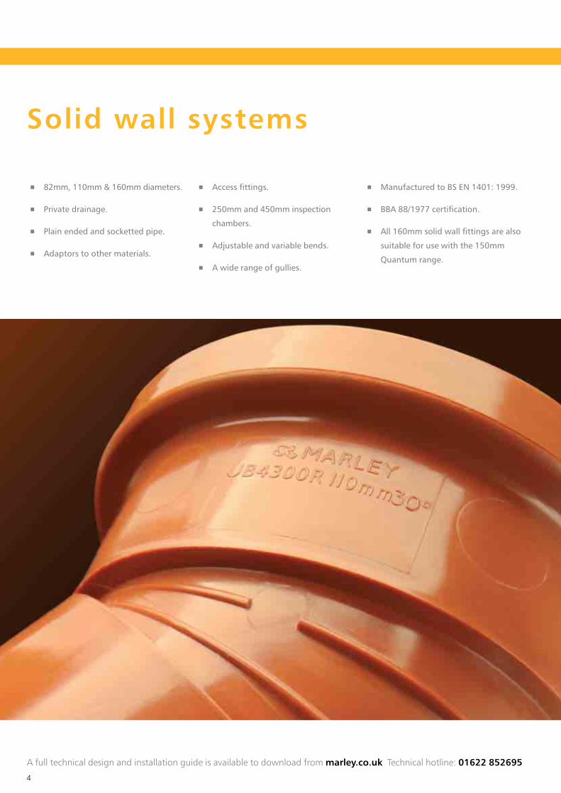
Solid wall systems
82mm, 110mm & 160mm diameters.
Private drainage.
Plain ended and socketted pipe.
Adaptors to other materials.
Access fittings.
250mm and 450mm inspection
chambers.
Adjustable and variable bends.
A wide range of gullies.
Manufactured to BS EN 1401: 1999.
BBA 88/1977 certification.
All 160mm solid wall fittings are also
suitable for use with the 150mm
Quantum range.

u n d e r g r o u n d
5
T h e s y s t e m s
PipeUP406
Gully hopper UG47
PipeUP406
PipeUP406
Slip couplingUE405
Inspection chamberUCC7
Inspection chamber baseUCC3/UCC5
Inspection chamber riser UCR2
Straight channelUCC4
CouplingUE407
45º short radius bendUB45
45º short radius bendUB455R
Long radius bendUBL488
Inspection chamber lid UCL3
P trap gullyUG42
Bottle gully UG50
Bottle gully raising piece UG52
Compact gullyUG40
45º short radius bendUB45
Chamber lid & coverUCL35/UCL35PP
45º short radius bendUB45
Diagram for illustrative purposes only

6
A full technical design and installation guide is available to download from marley.co.uk Technical hotline: 01622 852695
Structured wall systems
Marley Quantum was developed in 1991. The objective was to maximise the structural performance of plastic pipes and to produce
a pipe that was lightweight and easy to install on site. This in turn reduces the overall installation cost.
Quantum is manufactured in two
grades, sewer and highway, and
offers the following benefits over
traditional materials
The flexibility to tolerate ground
movement without damage, whilst
withstanding the combined effects
of backfill and loading.
Fewer joints to reduce the likelihood
of leaks and blockages.
A high level of chemical resistance to
the wide range of substances found in
both effluent and contaminated soils.
A smooth bore gives good
hydraulic performance.
A red stripe, printed down the
length of the pipe, aids identification
of sewer pipe.
BBA 94/2985 certification on
Quantum Sewer for private foul and
surface water applications.
BBA 09/H146 & BBA 98/3486
certification on Quantum Highway.
WIS 4-35-01 certification on
Quantum Sewer for adoptable foul
and surface water sewers.
Quantum Sewer
Available in 150mm, 225mm &
300mm diameters.
Suitable for:
Adoptable foul and surface
water sewers
Private foul and surface
water applications
Quantum Highway
Available in 150mm, 225mm,
300mm, 400mm, 500mm &
600mm diameters.
Suitable for:
Highway surface water carrier
and filter drains
Private surface water applications

u n d e r g r o u n d
7
T h e s y s t e m s
150x110mm branchUMY10Q
Chamber lid & coverUCL35/UCL35PP
Soil pipeSP403
RainwaterpipereducerRRM425
PipeUL406
Shortradius bendUB411
Inspection chamber riserUCR2
Longradius bendUBL488
150mm foul sewerULS13/ULS16
150mm surface water sewerULS13/ULS16
Large diameter Quantum Highway
Available in 400mm(i), 500mm(ii) and 600mm diameters.
Half slotted versions available in 400mm and 500mm diameters.
Meets the requirements of The Specification for Highway works, clause 501-3.
BBA 06/H122 certification.
(i) 18% greater capacity than 375mm concrete(ii) over 50% greater capacity than 400mm concrete

8
The Marley underground drainage range offers a comprehensive range of standard fittings including bends, branches and couplings.
Pictured is a selection of key components within the range.
For a complete listing of the below ground range, see pages 27-31.
450x110mm chamber base (UCC3D), riser (UCR3), access ring (UCLRR), lid (UCL35PP) & clip (UCC10D)
450x160mm chamber base (UCC5), riser (UCR2), lid (UCL35PP) & clip (UCC10)
250mm chamber (UCC7) & lid (UCL2)250mm chamber (UCC7) & lid (UCL3)
Inspection chambers
250mm and 450mm inspection
chambers can be used as an alternative
to traditional manholes for standard
and deep inspection. See page 16-19
for installation data.
(see below ground price list, pages 11-16)
A full technical design and installation guide is available to download from marley.co.uk Technical hotline: 01622 852695
Key components

u n d e r g r o u n d
9
The Marley non-return valve (USW120)
The Marley non-return valve is a simple and effective way to eliminate backflow
through drainage systems. The flap in the valve opens to allow discharge. In a
potential flood situation, the rising water levels seal the flap shut, alleviating the
risk of the water backing up into a property.
The internal profile is designed to avoid any interrupted flow and provides full access
for pipe cleaning or rodding. (see below ground price list, page 39)
Bottle gully (UG50)
Ideal for new or replacement installations. Accepts waste and rainwater pipes.
A fully rotating gully body allows the outlet to face the required direction
of the drain connection.
A removable rubber plug provides access for rodding.
UG52 optional raising piece available.(see below ground price list, page 19)
Non-return valve (USW120)
Bottle gully (UG50)
Ke y c o m p o n e n t s
Adjustable bends
Available in 82, 110 and 160mm with
a solvent weld joint or as 110mm
mechanical or multiflex bends.
The solvent weld bend can be adjusted
by cutting the fitting at the required
angle and solvent welding the two
sections together.
UB37 11º – 87½º
UB47 21º – 90º
UB67 15º – 90º
The mechanical bend provides a ‘twist
and lock‘ solution to achieve the
desired angle of between 5º and 30º.
(see below ground price list, page 7)
Multiflex bends are available as
socket/spigot or socket/socket (shown)
and can adjusted from 0º-90º.
Adjustable bend (UB47) Mulitflex bend (MFBDO)Mechanical bend (UB47M)
Code Angle achieved

10
Statutory requirementsThe following standards deal with drainage design:
and Sewers.
The design and layout of drainage and sewerage systems
should comply with The Building Regulations and Water
Authority Specification. Reference should also be made to the
Sewers for Adoption manual.
The following information is provided only as a general
guide to good practice for the design of underground
drainage systems. For full details please consult the relevant
documents referred to above.
Design
Foul water drainage systems are generally designed to run at
a maximum of three quarters full bore. Pipe gradients should
be established such that the velocity does not fall below 0.70
m/s to ensure adequate self-cleansing.
A 110mm foul drain taking the discharge from a single stack
should be laid at a 1:40 (25mm per metre) fall. A foul drain
taking the discharge from more than one stack can be laid at
1:80 (12.5mm per metre).
Gullies incorporating in foul water or combined drainage
systems must have a 50mm minimum water seal.
The table opposite is taken from BS EN 752 2008 and provides
guidance on minimum gradients for different size drains
Gradientslitres/second size (mm) gradient
<1 82 1:40
110 1:40
>1 82 1:80
110 1:80 (b)
160 1:150 (c)
(a) Peak flow based on probability flow calculation method
Surface water drainage systems may be designed to run full
bore. Drains taking multiple rainwater pipes can be laid to a
fall of 1:100 (10mm per metre).
Access is required to drainage installations for testing,
inspection and removal of debris. Access to drainage allowing
rodding in both directions can be provided by inspection
chambers, manholes and other access fittings. Rodding eyes
provide access for clearance of debris in the direction of flow
only and should thus be used in conjunction with an access
chamber or manhole at a point downstream.
No part of the drain or sewer should be more than 50m
away from a manhole. The distance between points should
therefore not exceed 100m.
For full guidance as to provision of access, reference should
be made to BS EN 752 2008. The table below details the
maximum spacing of the access points as detailed in the
above standard.
Means of access
Access fitting To branch Shallow Manhole or deep
1 2 or junction inspection chamber inspection chamber
Start of external drain* 12 12 - 22 45Rodding eye 22 22 22 45 45Type 1 access fitting 150 x 100mm - - 12 22 22Type 2 access fitting 225 x 100mm - - 22 45 45Shallow inspection chamber 22 45 22 45 45Manhole or deep inspection chamber - - - 45 90
* Stack or ground floor appliance

u n d e r g r o u n d
11
Physical characteristics
Dimensions and weights
Pipe BS nominal size (mm) Min Max Wall thickness (mm) Weight kg/metre
Solid wall 82 82.4 82.7 3.0 1.2110 110.0 110.3 3.2 1.7160 160.0 160.4 4.0 3.0
Quantum Sewer 150 145 160 - 1.85225 226 250 - 4.20300 297 330 - 7.00
Quantum Highway 150 148 160 - 1.25225 230 250 - 2.75300 302 330 - 4.65400 396 465 - 8.50500 496 580 - 13.30600 598 700 - 20.83
Pipe strength
Minimum short-term ring stiffness Marley solid wall 110mm 6000Marley solid wall 160mm 4000
Minimum short-term ring stiffness Quantum Sewer - 8000Quantum Highway - 6000
Minimum two-year ring stiffness Quantum Sewer - 4000Quantum Highway - 3000
Solid wall perforated pipe110mm solid wall perforated pipe is manufactured to the
dimensional requirements of BS EN 1401-1:1999. Pipe has two
rows of slots that are 60mm apart and 1.75mm wide. Slot sizes
as detailed in the table below.
Pipe size Slot width Slot length Slotted pipe (mm) (mm) (mm) (mm2/m)
110 1.75 24 2041
Quantum perforated pipesThree sizes of Quantum Highway perforated pipes are
available, 150, 225 and 300mm, half or fully slotted.
400 and 500mm are available half slotted.
Nominal Slot width Slot length Area half Area fullypipe size (mm) (mm) slotted pipe slotted pipe
(mm) (mm2/m) (mm2/m)
150 1.5 22 3000 6000225 1.5 38 3500 7000300 1.5 58 4000 8000400 3.5 45 18900 –500 3.5 50 19200 –
The slotted cross sectional area for both solid wall and
Quantum pipes exceed the perforation requirements of
the Department of Transport ‘Specification for Highway
Works’ 2001. This requires a minimum perforated area of
1000mm2/m irrespective of pipe diameter.
60º60º60º
Halfslotted pipe
(150, 225 & 300mm)
Halfslotted pipe
(400 & 500mm)
Fullyslotted pipe
45º60mm
120º

12
Installation data: Pipe laying
Angle of unsupportedtrench to bein accordance with BS EN 1610
Trench width in accordance withBS EN 1610 Tables 1 & 2
Pipe OD+ 300mm
Pipe OD+BeddingdepthSub trench
excavatedas shown
Trenches should not be open for
extended periods in advance of pipe
laying and should be backfilled as soon
as possible. It is essential that the sides
of the trench are adequately supported
during pipe laying. Trench widths
should be as narrow as is practicable
but not less than the pipe diameter plus
300mm to allow adequate sidefill to
be placed. Deeper excavations should
ideally incorporate a sub-trench in
accordance with the diagram opposite.
Excavation
The following information is based on the recommendations in BS 5955: Part 6
guide to good practice in the selection of bedding and backfill materials for Marley solid wall and Quantum underground drainage systems.
Suitable imported granular material
wall and Quantum Pipes for private and
adoptable sewer applications is detailed
in the table right:
Grading complying with the
requirements of BS EN 1610. Granular
material also includes aggregates for
concrete to BS EN 12620.
Granular material for bed & surround of PVCu drains and sewers
Nominal pipe size Granular material size
100/110mm 10mm nominal single-size
14 to 5mm course graded
150/160mm 10 or 14mm nominal single-size
14 to 5mm course graded
150/225mm 10,14 or 20mm nominal single-size
and over 14 or 20 to 5mm course graded
A full technical design and installation guide is available to download from marley.co.uk Technical hotline: 01622 852695
u n d e r g r o u n d
13
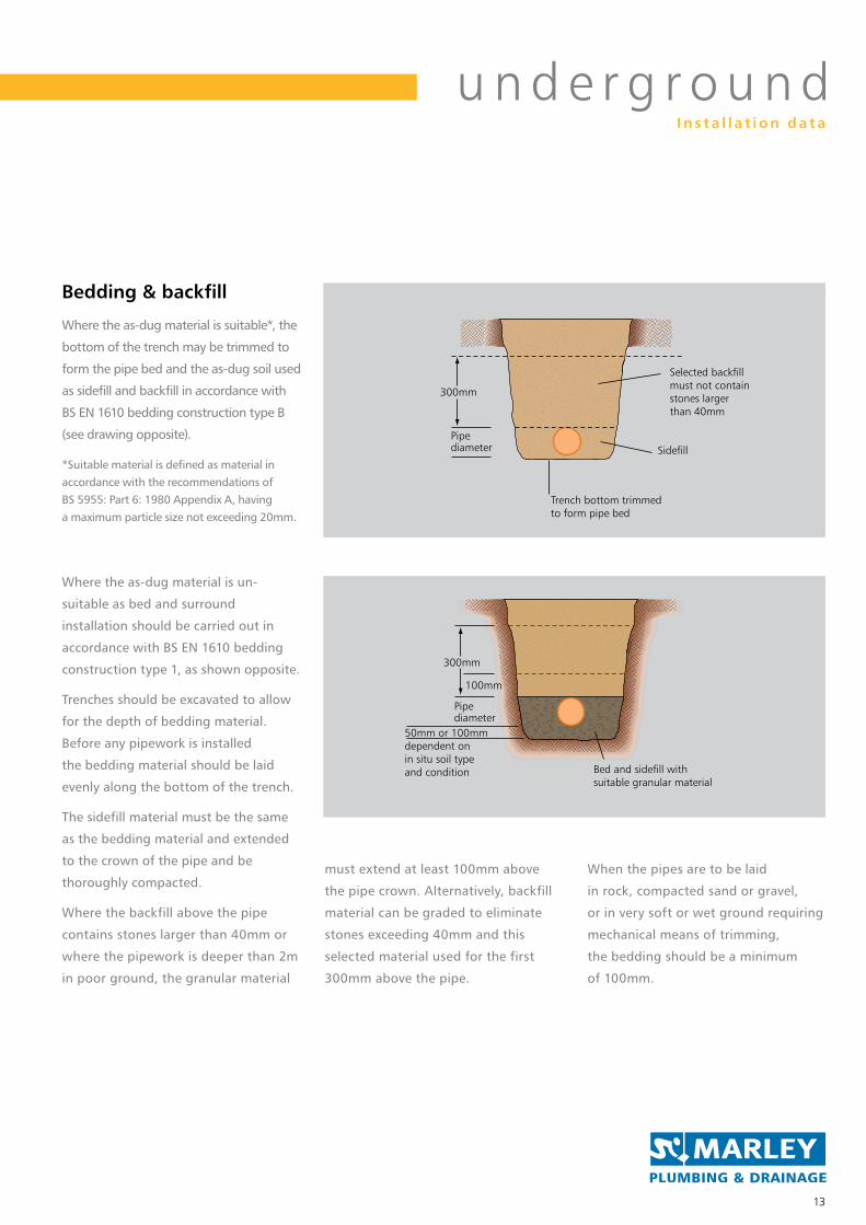
Where the as-dug material is un-
suitable as bed and surround
installation should be carried out in
accordance with BS EN 1610 bedding
construction type 1, as shown opposite.
Trenches should be excavated to allow
for the depth of bedding material.
Before any pipework is installed
the bedding material should be laid
evenly along the bottom of the trench.
The sidefill material must be the same
as the bedding material and extended
to the crown of the pipe and be
thoroughly compacted.
Where the backfill above the pipe
contains stones larger than 40mm or
where the pipework is deeper than 2m
in poor ground, the granular material
must extend at least 100mm above
the pipe crown. Alternatively, backfill
material can be graded to eliminate
stones exceeding 40mm and this
selected material used for the first
300mm above the pipe.
When the pipes are to be laid
in rock, compacted sand or gravel,
or in very soft or wet ground requiring
mechanical means of trimming,
the bedding should be a minimum
of 100mm.
Bed and sidefill withsuitable granular material
Pipediameter
300mm
100mm
50mm or 100mmdependent on in situ soil type and condition
Where the as-dug material is suitable*, the
bottom of the trench may be trimmed to
form the pipe bed and the as-dug soil used
as sidefill and backfill in accordance with
BS EN 1610 bedding construction type B
(see drawing opposite).
*Suitable material is defined as material in accordance with the recommendations of BS 5955: Part 6: 1980 Appendix A, having a maximum particle size not exceeding 20mm.
Bedding & backfill
Selected backfill must not contain stones larger than 40mm
SidefillPipediameter
300mm
Trench bottom trimmed to form pipe bed
I n s t a l l a t i o n d a t a

14
accommodate ground movement and other differential
settlement that may occur under normal conditions.
Therefore, the use of concrete bed and surround is not
recommended and only under special circumstances, at very
shallow cover depths or where it is necessary to safeguard
foundations, should it be used. Where the use of concrete
bed and surround is unavoidable, it is recommended that
pipes are laid in 3 metre lengths and a compressible board
is shaped to fit around each joint. Pipes should also be
wrapped with polythene to prevent the ingress of cement
slurry into ring seal joints.
Concrete bed & surround
Installation data: Pipe laying
Pipes laid at depths less than 600mm and which are not
under a road should, where necessary, be protected against
damage by placing over them a layer of concrete, paving slabs
or similar. A minimum 75mm cushioning layer of granular
material must be laid between pipes and the slabs or concrete.
Where drains are laid in fields, additional protection may
be required from heavy vehicles and equipment. It is
recommended that the installation is carried out with
a concrete slab spanning the trench as shown for drains
under private roads (right).
Shallow domestic drains
Drains often have to be laid under buildings in order to connect
sanitary pipework which has been positioned some distance
from the outer walls. Where this occurs, deep hardcore within
the foundation boundaries should be compacted first. The
trench for the pipe should then be excavated and suitable
material employed for the bedding and backfilling operation.
If trenches are dug from original ground, pipes may be laid
and surrounded as necessary before the top layer of hardcore
is formed. Where a pipe passes through a wall or foundation
of a building, a lintel or sleeve should be built-in to provide
clearance around the pipe.
Drains under solid ground floors
Bed and surround withsuitable granular material
Paving slab
Pipediameter
Less than600mm
50mm or 100mmdependent on in situ soil type and condition
75mm min granular material
Bed and surround with suitable granular material
Trench dug out of compacted hardcore
100mm minPipe diameter
100mm
100mm
Concreteslab
backfill
polythenemembrane
For applications in accordance with DTP requirements, please refer to the technical design and installation guide, available to download from marley.co.uk

u n d e r g r o u n d
15
Bed and surround withsuitable granular material
150mm granular materialabove pipe crown
1.2 minunder highways
0.9m min elseware Initial backfill
material not less than 300mm thick heavy compactionequipment not to be used
Backfill compacted in layers not exceeding 250mm thick
Road construction
Pipe diameter
100mm min
Bed and surround withsuitable granular material
Selected backfill must not contain stones larger than 40mm
Pipe diameter
100mm
Lessthan
900mm100mm
minimum
Meshreinforcement
if required
Road construction
Concreteslab
spanningtrench
200m
m m
in
If the depth of cover under a road or
driveway is less than 0.9m, a concrete slab
spanning the trench width is required.
Drains under private roads
For adoptable sewer applications pipe
bedding details should be in accordance
with the Water Industry Specification
No.4-08-01. Selected as-dug material
may be used for bedding and sidefill
provided it meets the evaluation
procedure and compaction fraction
test values specified in WIS 4-08-01.
The minimum cover under public roads
should be 1.2m to the top of the pipe.
The above information is for general
guidance only and detailed proposals
with regard to bedding and sidefill
materials for sewers must be submitted
to the relevant Adopting Authority for
formal approval at the design stage
of the project.
Adoptable sewers under roads
I n s t a l l a t i o n d a t a

16
Installation data: Shallow inspection chambers
250mm inspection chambers
Local concrete surround
UCC7 250mm inspection chamber
UCL2 or UCL3 lid and frame
600mmmax
Bed and surround with
suitable granular material
UAC44 – 250mm Chamber base
250mm inspection chambers
250mm inspection chambers may be
used as an alternative to traditional
manholes for invert depths up to
600mm. Intermediate depths can
be accommodated by cutting the
chamber riser using a hard tipped
handsaw or similar.
chamber with push-fit inlet and
outlet sockets, making installation
quick and easy.
are available for use with 250mm
diameter inspection chambers and
meet the loading requirements of BS
left) with separate riser UAR1. Both
square or circular lids and frames are
suitable for use with this inspection
chamber assembly.
chambers are used to make a 90°
change of direction in the drain, 45°
bends should be fitted to the inlet and
outlet connections to maintain a level
invert through the chamber. It is also
recommended that the peak flow in
the drain is always discharged through
the main channel and chambers
are rotated accordingly on site to
accommodate this.
A full technical design and installation guide is available to download from marley.co.uk Technical hotline: 01622 852695

u n d e r g r o u n d
17
The 250mm bottom outlet inspection
collection point for branch drains from
one or more dwellings and may also
serve as a rodding and testing point
for the main drain. The 110mm bottom
outlet ensures that discharges from the
side branches are quickly transmitted
to the main drain which may be
situated directly under the chamber or
to one side at a lower level.
The bottom outlet chamber is ideal
for situations where the main drain
runs parallel to a building at a lower
level as this allows the chamber to be
positioned directly above the drain.
drop arrangement with a 45° branch
and bend to the main drain.
Each chamber has four 110mm spigot
inlets, three of which are open and
the fourth can be opened for use if
necessary. The UE43 plug can be used
to blank off connections not required
and the chamber riser UAR1 cut to
accommodate invert depths of less
than 600mm.
and frame can be used to provide
access to the chamber at ground level.
250mm bottom outlet inspection chambers
Local concrete surround
UAR1 riser
UAC02 chamber body
UCL2 or UCL3 lid and frame
600mm max
Bed and surround with
suitable granular material
UBL488
long radius bend
Alternative 45º
bend & branch
UE407
coupling
I n s t a l l a t i o n d a t a

18
Installation data: Inspection chambers
UCL35/UCL35PP/UCL125
cover and frame
UCC10
chamber
riser clip
Local concrete bed
and surround to frame
UCR2
chamber riser
UCC3 110mm or
UCC5 160mm base
Bed and surround with
suitable granular material
UCL125 ductile iron cover
and frame to BS EN 124
Class B125 for use in roads
Bond breaker around riser
(heavy duty DPC or similiar)
Surface
Concrete
surround
200mm deep
Chamber riser
450mm inspection chambers may be
used as an alternative to traditionally
constructed manholes for invert depths
of up to 1.2 metres. Intermediate
depths can easily be accommodated
by simply cutting a riser, between the
ribbed sections, to the desired height
using a fine tooth saw.
a 100mm bed of suitable as-dug or
granular material and care should be
taken to ensure the bedding material
is evenly compacted under the base
so that the chamber is fully supported.
During the installation stage and
prior to backfilling, it is recommended
that chamber riser retaining clips
alignment of the chamber during the
backfilling operation.
Sidefill material should extend to just
below ground level and the cast iron
cover and frame set in a concrete plinth.
Two versions of chamber base are
110/160mm inlets and 160mm outlet.
Both have ring seal socket connections.
chamber base to a riser, or jointing riser
to riser, the ring seal is always located
in the first groove, as detailed opposite.
To ease jointing it is recommended that
silicone lubricant is used.
compatible with 150mm Quantum pipe.
This is achieved by removing the snap
cap and seal from the chamber base
and inserting Quantum pipe into the
socket, with the seal located into the
first corrugation of pipe.
450mm inspection chambers are
designed to withstand water testing
in accordance with BS EN 1610.
450mm inspection chambers
A full technical design and installation guide is available to download from marley.co.uk Technical hotline: 01622 852695
110mm (UCC3) / 160mm (UCC5)
Ring seal

u n d e r g r o u n d
19
I n s t a l l a t i o n d a t a
For the installation of an inspection
chamber deeper than 1.2m, the
regulations require the clear
opening to be reduced to 350mm
to prevent man entry. Inspection and
maintenance should be carried out
by remotely operated equipment and
the maximum depth is limited to 4m.
Access is only permitted when there
is no other alternative.
For full details please refer to the
Building Regulations (England & Wales)
Approved Document H – Drainage &
Waste Disposal – April 2002 or Part 3 of
the Building (Scotland) Regulations 2004
BSEN 752 2008.
The 110mm deep inspection chamber
on the underside of the chamber and
to the chamber base.
Please note that the standard UCC3
chamber base and UCR2 riser are
not suitable for deep inspection
applications.
Featuring increased ring stiffness
over our standard inspection
inspection riser must be used for
all deep inspection applications.
Identifiable by tabs marked ‘Deep
Inspection’ on the inside, each riser is
480mm high (effective height 440mm)
and is supplied with a 450mm ring seal.
chambers for deep inspection.
the required restricted opening for
non-man entry.
450mm deep inspection chambers
Granular material
110mm or160mm pipe
UCC3D or UCC5
Local concrete bed & surround
UCLRRUCL35PP UCR3

20
Installation data: Gully combinationsA comprehensive range of gully components are available, allowing a wide variety of gully combinations to be assembled on site to accommodate different applications.
The square or rectangular gully hoppers
UG47/UG48 and the gully inlet raising
piece UW401 all have connections for
small diameter pipework above the trap
water level but below the gully grating.
Waste pipes can be connected using
standard Marley universal boss
adaptors, as illustrated.
The larger diameter upstands on the
square or rectangular gully hoppers
are designed to provide a solvent
socket connection for 68mm circular
rainwater pipes.
Square or rectangular gully hoppers 32, 40 or 50mm
waste pipe
SA411, 421, 420 boss adaptor
UG47 rectangular gully hopper
UG48 squaregully hopper
32, 40 or 50mm waste pipe
110mm pipe 110mm pipeKB1/2/3 bend
The double socket design of the UG42
P Trap Gully makes it ideal for use in
restricted spaces and allows the trap to
be orientated to suit the direction
of the outlet pipe.
Both the square UG48 and rectangular
UG47 hoppers can be connected to the
gully using a short length of 110mm
pipe cut to suit ground level.
The UG45 gully grating can also be
used with the UW401 raising piece to
receive waste pipe connections below
ground level.
P trap gully
32, 40 or 50mm waste pipe
P trap gully UG42
P trap gully UG42
110mm drain
110mmdrain
UG45 gully grating
SA411, 421, 420 boss adaptor
UW401raising piece
32, 40 or 50mm waste pipe
A full technical design and installation guide is available to download from marley.co.uk Technical hotline: 01622 852695

u n d e r g r o u n d
21
midway between external corrugations.
2. Remove sealing ring from gully frame spigot and place
in first corrugation of raising piece.
3. Lubricate and push fit raising piece into top of gully body.
4. Gully frame spigot can then be solvent welded into top
of raising piece. The gully grating may be secured to the
frame if necessary with two 6 x 13mm self tapping pan
head corrosion resistant screws (not supplied).
Installation procedure for bottle gully
The UG40 compact gully is simple in
design, it features a unique design of
baffle plate which, when removed,
provides full access to the main body
for cleaning and rodding purposes.
Where a very shallow invert is required
a UB45 110mm x 45° socket/spigot bend
can be connected into the gully outlet.
The larger boss upstands on the gully
accept 68mm rainwater pipe connections
and the smaller upstands allow 32, 40
and 50mm pipes to be connected using
the appropriate boss connector.
The UG50 bottle gully is ideal for new
or replacement installations and it
provides the facility for direct 110mm
connections and waste pipe connections
via boss adaptors.
The fully rotating gully body allows the
outlet to be orientated to suit the drain
connection. A removable rubber plug
provides access for cleaning.
The gully raising piece UG52 allows
the gully to be installed at depths up
to 520mm.
Compact gully
Bottle gully
32, 40 or 50mm waste pipe
UG52raising piece
110mmsolvent socket
32/40/50mm waste pipe or 68mm circular/65mm square downpipe
UG40 gully
rainwater pipe
SA411, 421, 420 boss adaptor
bottle gully UG50/UG50D
110mmsocket outlet
110mm outlet
I n s t a l l a t i o n d a t a

22
50mm pipe
SE41 reducer
Ring seal socket
110mm PVCu pipe
SA420 boss adaptor
Installation data: Making the connection
External rainwater pipes usually
connect direct to the drain or,
depending on the design of the
sewerage system, via a gully trap.
Where rainwater pipes connect
directly to a drain and are of different
sizes, a suitable reducer and adaptor
fitting will be required.
wall above and below ground drainage
systems are the same and therefore
direct connection may be achieved
without an adaptor.
Rainwater pipe connections
Isolated ground floor sanitary
appliances are frequently supplied with
their own 110mm drain in the form of
an oversized and unventilated branch.
There are two methods of connecting
waste pipework direct to drain. The
SRM402 reducer may be used and
solvent welded onto a plain spigot-
upstand of pipe.
With the SE41 reducer a flexible
connection is provided at floor level
as this fitting push fits into a ring seal
socket. Standard Marley boss adaptors
are used with both types of reducer.
Stub waste connections
40 or 32mm pipe
SE41 reducer
Ring seal socket
110mm PVCu pipe
SA421/411 boss adaptor
40 or 32mm pipe
SRM402 reducer
SA421/411 boss adaptor
110mm PVCu pipe
50mm pipe
SRM402 reducer
SA420 boss adaptor
110mm PVCu pipe
68mm circular rainwater pipe
SRM325 reducer
82mm PVCu pipe
82mm circular rainwater pipe
SRM304 reducer
Ring seal socket
110mm PVCu pipe
68mm circular rainwater pipe
RRM425 reducer
110mm PVCu pipe
65mm square rainwater pipe
RRM425 reducer
RLE2 adaptor
110mm PVCu pipe
A full technical design and installation guide is available to download from marley.co.uk Technical hotline: 01622 852695
110mm PVCu to 68mm circular rainwater pipe
110mm PVCu to 40 or 32mm pipe 110mm PVCu to 50mm pipe
82mm PVCu to 68mm circular rainwater pipe
110mm PVCu to 65mm square rainwater pipe
110mm PVCu to 40 or 32mm pipe 110mm PVCu to 50mm pipe
110mm PVCu to 82mm circular rainwater pipe

u n d e r g r o u n d
23
Various adaptor fittings are available
pipework to drainage systems
of other materials.
The UMA45 adaptor can be used to
connect 160mm solid wall drainage
pipes to BS EN 1401: 2000 to 150mm
diameter nominal size clayware pipes
as shown on page 25.
Connections to other materials
PVCu pipe socket to thin wall clayware socket
PVCu socket to stoneware/cast iron spigot
PVCu spigot to stoneware socket
PVCu pipe socket to thick wall clayware socket
110mm PVCu pipe
110mm PVCu pipe
110mmPVCu pipe
Stoneware/castiron spigot
UA41 adaptor
UA47adaptor
Stonewaresocket
UE407coupling
UCA40adaptor
UCA40adaptor
2:1 sandand cement
2:1 sandand cement
Thin wallclay pipe
Thin wallclay pipe
Gaskin
Gaskin
I n s t a l l a t i o n d a t a

24
Installation data: Making the connection
All 150mm Quantum sockets
have been designed for use with
Quantum pipes and 160mm solid
wall pipes to BS EN 1401: 2000.
To adapt a Quantum fitting to
accept 160mm solid wall drainage
UR61T must be fitted to the end
of the socket to enable a connection
to be made, as shown above.
Connection to 160mm solid wall pipe
Quantum pipes may be easily cut
to length on site if required using a
fine tooth saw. Saw cuts should be
made square to the pipe midway
between the corrugations. It is not
necessary to chamfer the end of the
pipe after cutting.
Unlike joints on standard solid wall
pipe, where the ring seal is located
in a housing within the socket, with
Quantum pipe the ring seal is fitted
around the pipe.
The procedure for jointing is as follows:
1. Ensure that the end of the pipe and
inside the socket are free from swarf,
grit, etc.
2. Fit seal into the first corrugation
of the pipe making sure that the
seal is correctly handed, as shown
above, and that it is not twisted.
3. Apply lubricant around the pipe
seal and inside the socket.
4. Push pipe fully into the socket either
by hand or by using a timber block
and lever on the other end of the pipe.
Quantum couplings, bends, branches
and reducers have an all socket
configuration and jointing these to
Quantum pipe is achieved in the same
way as described above.
Cutting and jointing Quantum pipes
Pipe cut between corrugations with fine tooth saw
Pipe socket or coupling
Quantum seal fitted in first corrugation of pipe and handed as shown
160mm solid wall pipe
150mmQuantum pipe
URM11 seal in first corrugation
SNC6 snap cap and seal UR6IT
UME15Qcoupling
A full technical design and installation guide is available to download from marley.co.uk Technical hotline: 01622 852695

u n d e r g r o u n d
25
The UMA45 adaptor may be used to
connect 150mm Quantum pipe to
Densleeve or Hepsleeve 188mm outside
diameter clayware pipe.
The adaptor is designed to allow Quantum
pipe to be jointed with clayware pipe
using a standard clayware pipe coupler.
Installation procedure
1. Remove factory fitted ‘T’ seal from
adaptor socket.
2. Fit Quantum seal on the pipe in
the 10th corrugation from the end
of the pipe ensuring the seal is
correctly handed.
3. Lubricate the seal and inside the
socket of the adaptor. Push the
adaptor over the pipe, ensuring the
pipe passes completely through the
adaptor until the end of the pipe
aligns with the end of the adaptor.
4. Lubricate the adaptor spigot
and push into the clayware pipe
coupler up to the central register.
Quantum to thick wall clayware
The same adaptor can also be used
to connect 150mm Quantum pipe
to Hepsleeve or Supersleeve 178mm
outside diameter clayware pipe. For
this application the end spigot of the
adaptor is first removed using a fine
tooth saw. The remaining section of the
adaptor is then suitable for connecting
directly into a standard polypropylene
clayware pipe coupler as shown above.
The installation sequence for
this application is similar to that
previously described but the seal is
fitted on the Quantum pipe in the 6th
corrugation from the end of the pipe
to take into account the shortened
length of the adaptor.
Quantum to thin wall clayware
The UMA45 adaptor can also be used
as supplied to connect 160mm solid
as shown above.
Solid wall PVCu pipe to clayware
The range of flexible couplings
allow connections to be made
between Quantum pipes and
pipes of other materials.
Flexible couplings
Connection to other materials
Thick wall clayware pipe
Thin wall clayware pipe
Thick wallclayware pipe
Quantumpipe with seal fitted in 10th corrugation
Quantumpipe with seal fitted in 6th corrugation
160mm solid wall PVCu pipe
Quantum pipe inserted full depth of adaptor
Quantum pipe inserted full depth of adaptor
Claywarepipe couplerClayware
pipe coupler
Claywarepipe coupler
UMA45 adaptor with integral seal removed
UMA45 adaptor with integral seal removed
UMA45 adaptor with integral seal
Flexiblecoupling
Other pipe materialQuantum
pipe
I n s t a l l a t i o n d a t a

26
British & European Standards
Also available from Marley
BS EN 12620: 2008, Aggregates
for concrete.
BS 4660 & BS EN 1401: 1999, Plastic
piping systems for non-pressure
underground drainage and sewerage.
BS 4962: 1989, Specification for
plastic pipes and fittings for use as
subsoil field drains.
BS 5955-6: 1980, Plastics pipework
of practice for the installation of
drains and sewers.
BS EN 14860: 2006, Adhesives for
non-pressure thermoplastic pipe systems.
BS 7158: 2001, Plastic inspection
chambers for drains and sewers.
BS EN 124: 1994, Manhole covers
and frames.
BS EN 295: 1991, Vitrified clay pipes
& fittings and pipe joints for drains
and sewers.
BS EN 681-1: 1996, Elastomeric seals.
Material requirements for pipe joint seals
used in water and drainage applications.
Vulcanised rubber.
BS EN 752: 2008, Drain & Sewer Systems
outside buildings.
BS EN 1295-1: 1998, Structural design of
buried pipelines under various conditions
of loading. General requirements.
BS EN 1610: 1998
Testing of Drains & Sewers.
BS EN 12056-2: 2000, Gravity drainage
systems inside buildings: Sanitary
pipework, layout and calculation.
BS EN 12056-3: 2000, Gravity drainage
systems inside buildings. Roof drainage,
layout and calculation.
BS EN 13476-3: 2007, Plastics piping
systems for non-pressure drainage
and sewerage, structured wall piping
systems with smooth bore and profiled
external surface.
BS EN ISO 9001-2: 2000, Quality
management systems.
BBA 88/1977, Marley Underground
Drainage System.
BBA 09/H146
Twinwall Drainage System.
BBA 94/2985, Marley Quantum Sewer
and Sewerage System.
BBA 98/3486, Marley Quantum
Drainage System.
WIS 4-08-01, Imported granular and
selected as-dug bedding and sidefill
materials for buried pipelines.
WIS 4-35-01: 2000,
Specification for Structured Wall Pipes:
Certificate No. 88/197794/2985 98/3486 06/H12209/H146
CERTI
FIE
DTO
W
ATER INDUSTRYSPEC
IFICATION
WIS 4-35-01
FM30637
BS 4660 : 1999BS EN 1401 : 1999
BS EN 13476-3 : 2007
CERTI
OW
ATE STRYSP
CATION
Stormwater

u n d e r g r o u n d
27
Solid WallProduct informationDescription Size Code
(mm)
Pipe3m 110 UL403
6m 110 UL406
Double spigot 6m 160 UL606
3m 82 UP303
3m 110 UP403
3m 160 UP603
6m 110 UP406
Push fit socket 6m 160 UP606
Perforated pipe
6m 110 UPP406
Push fit socket
Straight couplings
110 UE407
Push fit polypropylene ring seal
(Supplied in U.V. resistant polythene bags)
110 UE406
160 UME15C
Push fit coupling
82 UE305
110 UE405
Push fit slip coupling 160 UME16C
82 UE300
110 UE400
Loose pipe socket 160 UE600
110 UE402
Triple socket
Allows up to 150mm movement/settlement
Short radius bends
87½º 82 UB31
87½º 110 UB41
87½º 160 UFB61
45º 82 UB35
45º 110 UB45
45º 160 UFB65
30º ribbed 110 UB430R
30º 160 UB69
Description Size Code (mm)
Short radius bendsribbed 15º 110 UB415R
15º 160 UB68
Socket/spigot
87½º 110 UB411
87½º 160 UMB19C
45º 160 UMB14C
45º 110 UB455
ribbed 30º 110 UB4300R
30º 160 UMB13C
ribbed 15º 110 UB4155R
15º 160 UMB11C
Socket/socket
Adjustable bends11º – 87½º 82 UB37
21º – 90º 110 UB47
15º – 90º 160 UB67
Socket should be solvent welded
Multiflex bends
Socket/spigot 0-90º 110 MFBS0
Socket/socket 0-90º 110 MFBD0
Mechanical bend5-30º 110 UB47M
Long radius bends87½º 110 UBL488
Socket/socket
87½º 110 UBL49
Socket/spigot with 900mm tail
Equal branches45º 82 UY36
45º 110 UY46
45º 160 UY63
ribbed 110 UY46R
45º
87½º 110 UY401
87½º 160 UY601
Description Size Code (mm)
Equal branches
ribbed 110 UY401R
87½º
Socket/spigot
45º 110 UY466
45º 160 UMY11C
All Socket
ribbed 110 UY466R
45º
87½º 110 UY400
87½º 160 UMY13C
ribbed 110 UY400R
87½º
All socket
Unequal branches
45º 160x110 UY66
87½º 160x110 UY64
Socket/spigot
Unequal branches
45º 160x110 UMY10C
87½º 160x110 UMY12C
All socket
Access pipe
110 UF42
Socket/spigot
To BS EN 1401 UD SDR41, BS 4660: 2000 or BBA 88/1977 as appropriate.

28
Description Size Code (mm)
Rear access bend87½º 110 UB42
Socket/spigot
Access branches 45º equal 110 UY471
Left hand
45º equal 110 UY472
Right hand
Socket/spigot
Rodding point 45º 110 URP1
45º 160 URP2C
Socketed with black cover
Access cap110 UE42
160 UE62
Pressure plug 110 UE43
160 UE64
Socket plug 110 SE41
1 boss upstand
450mm inspection chamber base 110 UCC3
max invert depth 1.2m
160 UCC5
max invert depth 4m (when used with UCR3) all socket
connections
Chamber riser 110 UCR2
400mm high
Includes one 450mm seal
Description Size Code (mm)
Deep inspection chamber
110 UCC3D
All socket connections
Deep inspection chamber riser
110 UCR3
For use with UCC3D or UCC5 when invert depth is greater
than 1.2m. Max invert depth 4m
480mm high. Includes one 450mm seal
Reduced access ring
110 UCLRR
Provides 350mm restricted opening.
Snap lock connection to the frame of the UCL35PP
Inspection cover & frame
450 UCL35
Cast iron – 3.5 tonnes (class A15)
450 UCL35PP
Polypropylene for non-trafficked applications only
50 UCL125
Ductile iron – 12.5 tonnes (class B125)
Chamber riser clip
UCC10
Deep inspection chamber riser clip
UCC10D
Inspection chamber inserts
160 UCB1
Left hand
160 UCB2
Right hand
For use with UCC5 Inspection chamber
Description Size Code (mm)
Spare blanking plug 110 UCP1
160 UCP2
Spare ring seal 450 SR450
250mm level invert inspection chamber 110 UCC7
– Max invert, depth 600mm
All socket connections
250mm double branch chamber base 110 UAC44
45º equal connectors
Includes two socket plugs
250mm bottom outlet chamber body110 UAC02
90º equal connections
4 x 110mm upstands, 3 open
Chamber riser 250 UAR1
375mm long
For use with
UAC02 & UAC44
Lifting handleFor use with UAC44 110 KP204W
Inspection cover & frame 250 UCL2
PVCu (Class A15)
Spare ring seal 250 SR250
Optional for UCL2 PVCu lid
Inspection cover & frame 300 UCL3
PVCu (Class A15)
Solid WallProduct information
To BS EN 1401 UD SDR41, BS 4660: 2000 or BBA 88/1977 as appropriate.

u n d e r g r o u n d
29
Description Size Code (mm)
Grating components Grating assembly 110 UG45
Spare grating
suits UG40, 45, 47 & 48 110 UG46
Spare back plate
suits UG40 & UG47 110 UG49
Inlet raising pieces 2 x 82mm upstands 110 UWS43
4 boss upstands 110 UW401
Yard gully
634mm deep x 110 UYG40
315mm diameter
Grating and frame 110 UYG42
BS EN 124 class B125
12.5 tonnes
Adaptors
PVCu pipe socket to salt 110 UA41
glazed/pitch fibre pipe socket
Salt glazed/cast iron spigot 110 UA47
to PVCu spigot
Socket/socket to suit thin 110 UCA40
wall clayware spigot pipe
Socket/socket to suit thick 110 UCA41
wall clayware pipe
Rainwater to 110mm drain 110 UA42
Universal waste to 110 UA43
110mm drain
Description Size Code (mm)
Straight double spigot open channel
110 UCC4
1.5m long, with 600mm opening
Long radius channel bend
87½º 110 UCB48L
Socket/socket
Slipper bends
45° 110 USB41
Left hand
45° 110 USB42
Right hand
Level invert reducers
Spigot/socket 110-82 URM304
Spigot/socket 160-110 URM604
Eccentric reducers
82-50 SRM30
Solvent socket to boss upstand
82-68 SRM325
Solvent socket to 68mm downpipe
110-50 SRM402
Solvent socket to boss upstand
110-68 URM425
Solvent socket to 68mm downpipe
Concentric reducer
110-50 SE41
Spigot to boss upstand
Description Size Code (mm)
Bottle gully Bottle gully 110 UG50
Bottle gully with back inlet open
110 UG50D
Bottle gully with sealed access lid
110 UG50SA
A15 loading
Spare bottle gully grid Grid 110 UG51
Sealed access grid 110 UG51SA
For use with UG50 bottle gully
Bottle gully raising grid 110 UG52
Compact gully 110 UG40
45° outlet
‘P’ trap gully 110 UG42
81½º outlet
Gully trap base 110 UG44
45° outlet
Rectangular hopper 110 UG47
2 boss upstands
Square hopper
110 UG48
2 boss upstands
To BS EN 1401 UD SDR41, BS 4660: 2000 or BBA 88/1977 as appropriate.

30
Description Size Code (mm)
Quantum sewer pipe
3m 150 ULS13
3m 225 ULS23
3m 300 ULS33
6m 150 ULS16
Double spigot
3m 150 UPS13
3m 225 UPS23
3m 300 UPS33
6m 150 UPS16
6m 225 UPS26
6m 300 UPS36
Pipe with coupling and seals
Quantum highway pipe
6m 150 UPH16
6m 225 UPH26
6m 300 UPH36
Push-fit socket
6m 150 USH16
6m 225 USH26
6m 300 USH36
Half slotted socket
Order seals if required
6m 150 UHH16
6m 225 UHH26
6m 300 UHH36
Fully slotted socket
Order seals if required
Couplings
150 UME15Q
225 UME25
300 UME35
Straight
150 UME16Q
225 UME26
300 UME36
Slip
Description Size Code (mm)
Bends
87½º 150 UMB19Q
87½º 225 UMB29
87½º 300 UMB39
Double socket
45º 150 UMB14Q
45º 225 UMB24
45º 300 UMB34
Double socket
30º 150 UMB13Q
30º 225 UMB23
30º 300 UMB33
Double socket
15º 150 UMB11Q
15º 225 UMB21
15º 300 UMB31
Double socket
Equal branch
45º 150 UMY11Q
45º 225 UMY22
45º 300 UMY33
All socket
87½º 150 UMY13Q
All socket
Unequal branch
45º 150x110 UMY10Q
87½º 150x110 UMY12Q
Description Size Code (mm)
Unequal branch
45º 225x100 UMY20
45º 300x150 UMY31
45º 225x150 UMY21
45º 300x225 UMY32
45º 300x110 UMY30
Plugs
150 UMJ11
Socket Plug
150 UMK11
225 UMK21
300 UMK31
End Cap
Level invert reducer
225x50 UML21
300x225 UML32
Adaptors
150 UMA45
Quantum/solid wall
PVC to clayware pipe coupler
Quantum Structured WallProduct information
To BBA 94/2985, 09/H146 or 98/3486 as appropriate. Quantum Sewer pipe to WLS 4-35-01.

u n d e r g r o u n d
31
Description Size Code (mm)
Adaptors
150 UMA17
Quantum socket to solid wall spigot
Flexible coupling
150 UMD17
225 UMD27
300 UMD37
Flexible gully connecting pipe
50m length 150 UMA44
Pipe seals
Quantum pipe seal (1) 150 UMR11
225 UMR21
300 UMR31
Seal to convert 150 UR61T
Quantum 150mm
sockets for use with
BS EN 1401 pipe
Seal cap to convert 150 SNC6
Quantum 150mm
sockets for use with
BS EN 1401 pipe
Quantum seal pack
2 x UMR21 + 1 x UMR11 225 UMR24
2 x UMR31 + 1 x UMR11 300 UMR34
2 x UMR31 + 1 x UMR21 300 UMR35
Description Size Code (mm)
Polyethylene gully pot liner(500mm diameter)
90 litres (760mm deep) 150 UMA43
112 litres (920mm deep) 150 UMA49
Rodding point 45º 150 URP2Q
Aluminium cover
Lubricant 1kg UMA41
Quantum highway pipe6m 400 UPH46
6m 500 UPH56
6m 600 UPH66
Push-fit socket
Quantum highway pipe6m 400 USH46
6m 500 USH56
Half slotted socket
Coupling
400 UME45Q
500 UME55Q
Description Size Code (mm)
Coupling
600 UME65Q
Straight
Bend
45º 400 UMB44
45º 500 UMB54
45º 600 UMB64
Double socket
Unequal branch
45º 400x225 UMY42
45º 500x225 UMY52
45º 400x150 UMY41
45º 500x150 UMY51
45º 600x150 UMY61
Pipe seals
Quantum pipe seal (1) 400 UMR41
500 UMR51
600 UMR61
Seals are supplied separately and
should be ordered in addition to
pipe and fittings.
Branches are spigot ended and
need to be used in conjunction
with couplings and seals.
To BBA 94/2985, 09/H146, 98/3486 or 06/H122 as appropriate.

Head OfficeLenham, Maidstone, Kent ME17 2DETelephone: 01622 858888Fax: 01622 858725marley.co.uk
ScotlandBirkenshaw Industrial EstateUddingston, Glasgow G71 5PATelephone: 01698 815231Fax: 01698 810307
Export DivisionLenham, Maidstone Kent ME17 2DE EnglandTelephone: +44 (0)1622 858888Fax: +44 (0)1622 850778
Further informationFor Technical advice please call 01622 852695For general enquiries and details of your nearest stockist please call the customer services department on 01622 852585email: [email protected]