
May 17, 20002 Electrical Detail Marq Kole Royal Philips Electronics Jon Lueker Intel Corporation.
32
-
Upload
yolanda-pettingill -
Category
Documents
-
view
217 -
download
0
Transcript of May 17, 20002 Electrical Detail Marq Kole Royal Philips Electronics Jon Lueker Intel Corporation.


May 17, 2000 2
Electrical DetailElectrical DetailMarq KoleMarq Kole
Royal Philips ElectronicsRoyal Philips Electronics
Jon LuekerJon LuekerIntel CorporationIntel Corporation
May 17, 2000 3
Speed Detection, Reset, and Suspend / Resume
in USB 2.0
Speed Detection, Reset, and Suspend / Resume
in USB 2.0
May 17, 2000 4
ContentsContents
High-speed Capability DetectionHigh-speed Capability Detection ResetReset SuspendSuspend Reset from suspendReset from suspend ResumeResume
May 17, 2000 5
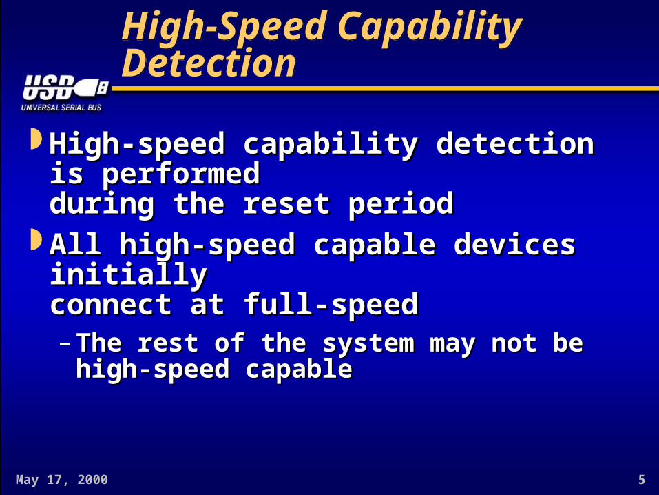
High-Speed Capability DetectionHigh-Speed Capability Detection
High-speed capability detection is performedHigh-speed capability detection is performedduring the reset periodduring the reset period
All high-speed capable devices initiallyAll high-speed capable devices initiallyconnect at full-speedconnect at full-speed– The rest of the system may not beThe rest of the system may not be
high-speed capablehigh-speed capable

May 17, 2000 6
ResetReset
USB 1.1 Reset protocol is extended with resetUSB 1.1 Reset protocol is extended with resetsignaling for high-speed hubs and devicessignaling for high-speed hubs and devices
Extensions are compatible with USB 1.1:Extensions are compatible with USB 1.1:– Any USB 1.1 host/hub is able to reset anyAny USB 1.1 host/hub is able to reset any
USB 2.0 hub/deviceUSB 2.0 hub/device– Additional Speed Detection Mechanism does notAdditional Speed Detection Mechanism does not
confuse a USB 1.1 hub/deviceconfuse a USB 1.1 hub/device Reset of a high-speed device takes the sameReset of a high-speed device takes the same
10 ms minimum duration as USB 1.1 devices 10 ms minimum duration as USB 1.1 devices

May 17, 2000 7
Reset HandshakeReset Handshake
High-speed capable hubs and devices performHigh-speed capable hubs and devices performa handshake to detect each others high-speeda handshake to detect each others high-speedcapabilities;capabilities;
A High-speed Capable Device will initiate theA High-speed Capable Device will initiate thehandshake (“Hello, I can do High-speed”);handshake (“Hello, I can do High-speed”);
A High-speed Capable Hub responds to theA High-speed Capable Hub responds to thehandshake (“Great, I can do High-speed, too”);handshake (“Great, I can do High-speed, too”);
After the handshake, both will communicate inAfter the handshake, both will communicate inHigh-speed mode.High-speed mode.
Reference implementation in Appendix CReference implementation in Appendix C

May 17, 2000 8
Timeline for ResetTimeline for Reset
μSOFμSOF Device ChirpDevice Chirp Hub ChirpHub Chirp
D+
D–
3.0-3.125 ms 100-875 μs < 500 μs> 1.0 ms
< 7.0 ms
< 100 μs 100-500 μs> 10 ms
End ofDevice Chirp
Start ofDevice Chirp
Start ofReset
Devicerevertsto FS
Devicerevertsto HS
Devicedetects
Hub Chirp
Start ofReset
End ofReset
End ofHub Chirp
Start ofHub Chirp
μSOFμSOF
Hub
Dev
ice
SE0SE0 SE0SE0SE0SE0 HS idleHS idle
May 17, 2000 9
SE0 & T1 SE0 & T1 T TWTRSTHSWTRSTHSSE0 & T1 SE0 & T1 T TWTRSTHSWTRSTHSSE0 & T1 SE0 & T1 T TWTRSTHSWTRSTHSSE0 & T1 SE0 & T1 T TWTRSTHSWTRSTHS
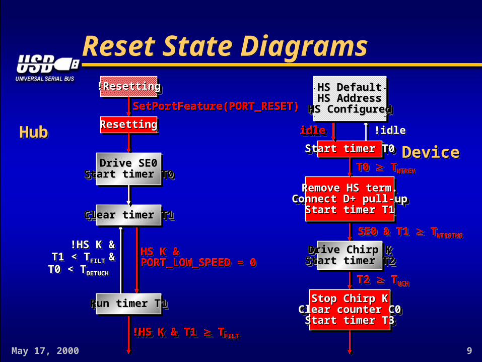
Reset State DiagramsReset State DiagramsHS DefaultHS Default
HS AddressHS AddressHS ConfiguredHS Configured
HS DefaultHS DefaultHS AddressHS Address
HS ConfiguredHS Configured
Start timer T0Start timer T0Start timer T0Start timer T0
Remove HS term.Remove HS term.Connect D+ pull-upConnect D+ pull-up
Start timer T1Start timer T1
Remove HS term.Remove HS term.Connect D+ pull-upConnect D+ pull-up
Start timer T1Start timer T1
idleidle !idle!idle!idle!idle
T0 T0 T TWTREVWTREVT0 T0 T TWTREVWTREV
!Resetting!Resetting!Resetting!Resetting
ResettingResettingResettingResetting
Drive SE0Drive SE0Start timer T0Start timer T0
Drive SE0Drive SE0Start timer T0Start timer T0
Clear timer T1Clear timer T1Clear timer T1Clear timer T1
Run timer T1Run timer T1Run timer T1Run timer T1
SetPortFeature(PORT_RESET)SetPortFeature(PORT_RESET)
HS K &HS K &PORT_LOW_SPEED = 0PORT_LOW_SPEED = 0HS K &HS K &PORT_LOW_SPEED = 0PORT_LOW_SPEED = 0
!HS K &!HS K &T1 < TT1 < TFILT FILT &&
T0 < TT0 < TDETUCHDETUCH
!HS K &!HS K &T1 < TT1 < TFILT FILT &&
T0 < TT0 < TDETUCHDETUCH
!HS K & T1 !HS K & T1 T TFILTFILT
Drive Chirp KDrive Chirp KStart timer T2Start timer T2Drive Chirp KDrive Chirp KStart timer T2Start timer T2
T2 T2 T TUCHUCHT2 T2 T TUCHUCH
Stop Chirp KStop Chirp KClear counter C0Clear counter C0
Start timer T3Start timer T3
Stop Chirp KStop Chirp KClear counter C0Clear counter C0
Start timer T3Start timer T3
DeviceDeviceDeviceDeviceHubHubHubHub
HS DefaultHS DefaultHS AddressHS Address
HS ConfiguredHS Configured
HS DefaultHS DefaultHS AddressHS Address
HS ConfiguredHS Configured
Start timer T0Start timer T0Start timer T0Start timer T0
Remove HS term.Remove HS term.Connect D+ pull-upConnect D+ pull-up
Start timer T1Start timer T1
Remove HS term.Remove HS term.Connect D+ pull-upConnect D+ pull-up
Start timer T1Start timer T1
idleidleidleidle
T0 T0 T TWTREVWTREVT0 T0 T TWTREVWTREV
!Resetting!Resetting!Resetting!Resetting
ResettingResettingResettingResetting
Drive SE0Drive SE0Start timer T0Start timer T0
Drive SE0Drive SE0Start timer T0Start timer T0
Clear timer T1Clear timer T1Clear timer T1Clear timer T1
Run timer T1Run timer T1Run timer T1Run timer T1
SetPortFeature(PORT_RESET)SetPortFeature(PORT_RESET)
HS K &HS K &PORT_LOW_SPEED = 0PORT_LOW_SPEED = 0
!HS K & T1 !HS K & T1 T TFILTFILT!HS K & T1 !HS K & T1 T TFILTFILT
Drive Chirp KDrive Chirp KStart timer T2Start timer T2Drive Chirp KDrive Chirp KStart timer T2Start timer T2
T2 T2 T TUCHUCHT2 T2 T TUCHUCH
Stop Chirp KStop Chirp KClear counter C0Clear counter C0
Start timer T3Start timer T3
Stop Chirp KStop Chirp KClear counter C0Clear counter C0
Start timer T3Start timer T3
HS DefaultHS DefaultHS AddressHS Address
HS ConfiguredHS Configured
HS DefaultHS DefaultHS AddressHS Address
HS ConfiguredHS Configured
Run timer T1Run timer T1Run timer T1Run timer T1
Drive SE0Drive SE0Start timer T0Start timer T0
Drive SE0Drive SE0Start timer T0Start timer T0
Clear timer T1Clear timer T1Clear timer T1Clear timer T1
Drive Chirp KDrive Chirp KStart timer T2Start timer T2Drive Chirp KDrive Chirp KStart timer T2Start timer T2

May 17, 2000 10
Drive Chirp KDrive Chirp KStart timer T2Start timer T2Drive Chirp KDrive Chirp KStart timer T2Start timer T2
Reset State Diagrams (cont.)Reset State Diagrams (cont.)
HS DefaultHS DefaultHS DefaultHS Default
Clear timer T4
Increase C0
Run timer T4
Clear timer T4
Run timer T4
T4 T4 T TFILTFILTT4 T4 T TFILTFILT
T4 T4 T TFILTFILTT4 T4 T TFILTFILT
HS KHS KHS KHS K !HS K & T4 < T!HS K & T4 < TFILTFILT!HS K & T4 < T!HS K & T4 < TFILTFILT
HS JHS JHS JHS J !HS J & T4 < T!HS J & T4 < TFILTFILT!HS J & T4 < T!HS J & T4 < TFILTFILT
Enable HS term.Enable HS term.Disconnect D+ pull-upDisconnect D+ pull-up
Enable HS term.Enable HS term.Disconnect D+ pull-upDisconnect D+ pull-up
C0 < 3 &C0 < 3 &T3 < TT3 < TWTFSWTFS
C0 < 3 &C0 < 3 &T3 < TT3 < TWTFSWTFS
C0 C0 3 3C0 C0 3 3
Drive Chirp KStart timer T2
HS DefaultHS DefaultHS DefaultHS Default
T0 T0 T TDRSTDRSTT0 T0 T TDRSTDRST
!HS K & T1 !HS K & T1 T TFILTFILT!HS K & T1 !HS K & T1 T TFILTFILT
Drive Chirp JStart timer T2
Drive SE0Drive SE0Drive SE0Drive SE0
T2 T2 T TDCHBITDCHBIT & &T0 T0 T TDRSTDRST - T - TDCHSE0DCHSE0
T2 T2 T TDCHBITDCHBIT & &T0 T0 T TDRSTDRST - T - TDCHSE0DCHSE0
T2 T2 T TDCHBITDCHBIT & & T0 T0 T TDRSTDRST - T - TDCHSE0DCHSE0
T2 T2 T TDCHBITDCHBIT & & T0 T0 T TDRSTDRST - T - TDCHSE0DCHSE0
T2 T2 T TDCHBIT DCHBIT &&T0 < TT0 < TDRSTDRST - T - TDCHSE0DCHSE0 T2 T2 T TDCHBIT DCHBIT &&T0 < TT0 < TDRSTDRST - T - TDCHSE0DCHSE0
T2 T2 T TDCHBIT DCHBIT &&T0 < TT0 < TDRSTDRST - T - TDCHSE0DCHSE0
T2 T2 T TDCHBIT DCHBIT &&T0 < TT0 < TDRSTDRST - T - TDCHSE0DCHSE0
DeviceDeviceDeviceDeviceHubHubHubHub
Clear timer T4Clear timer T4Clear timer T4Clear timer T4
Increase C0Increase C0Increase C0Increase C0
Run timer T4Run timer T4Run timer T4Run timer T4
Clear timer T4Clear timer T4Clear timer T4Clear timer T4
Run timer T4Run timer T4Run timer T4Run timer T4
T4 T4 T TFILTFILTT4 T4 T TFILTFILT
T4 T4 T TFILTFILTT4 T4 T TFILTFILT
HS KHS KHS KHS K
HS JHS JHS JHS J
C0 < 3 &C0 < 3 &T3 < TT3 < TWTFSWTFS
C0 < 3 &C0 < 3 &T3 < TT3 < TWTFSWTFS
Drive Chirp KDrive Chirp KStart timer T2Start timer T2Drive Chirp KDrive Chirp KStart timer T2Start timer T2
!HS K & T1 !HS K & T1 T TFILTFILT!HS K & T1 !HS K & T1 T TFILTFILT
Drive Chirp JDrive Chirp JStart timer T2Start timer T2Drive Chirp JDrive Chirp JStart timer T2Start timer T2
T2 T2 T TDCHBIT DCHBIT &&T0 < TT0 < TDRSTDRST - T - TDCHSE0DCHSE0
T2 T2 T TDCHBIT DCHBIT &&T0 < TT0 < TDRSTDRST - T - TDCHSE0DCHSE0
Clear timer T4Clear timer T4Clear timer T4Clear timer T4
Clear timer T4Clear timer T4Clear timer T4Clear timer T4
Drive Chirp KDrive Chirp KStart timer T2Start timer T2Drive Chirp KDrive Chirp KStart timer T2Start timer T2
Drive Chirp JDrive Chirp JStart timer T2Start timer T2Drive Chirp JDrive Chirp JStart timer T2Start timer T2
T2 T2 T TDCHBIT DCHBIT &&T0 < TT0 < TDRSTDRST - T - TDCHSE0DCHSE0 T2 T2 T TDCHBIT DCHBIT &&T0 < TT0 < TDRSTDRST - T - TDCHSE0DCHSE0
T4 T4 T TFILTFILTT4 T4 T TFILTFILT
T4 T4 T TFILTFILTT4 T4 T TFILTFILT
HS KHS KHS KHS K
HS JHS JHS JHS J
T2 T2 T TDCHBIT DCHBIT &&T0 < TT0 < TDRSTDRST - T - TDCHSE0DCHSE0
T2 T2 T TDCHBIT DCHBIT &&T0 < TT0 < TDRSTDRST - T - TDCHSE0DCHSE0
Increase C0Increase C0Increase C0Increase C0
Run timer T4Run timer T4Run timer T4Run timer T4
Run timer T4Run timer T4Run timer T4Run timer T4

May 17, 2000 11
Drive Chirp KStart timer T2Drive Chirp KStart timer T2Drive Chirp KDrive Chirp KStart timer T2Start timer T2Drive Chirp KDrive Chirp KStart timer T2Start timer T2Drive Chirp KStart timer T2Drive Chirp KStart timer T2
Clear timer T4Clear timer T4Clear timer T4Clear timer T4Clear timer T4Clear timer T4
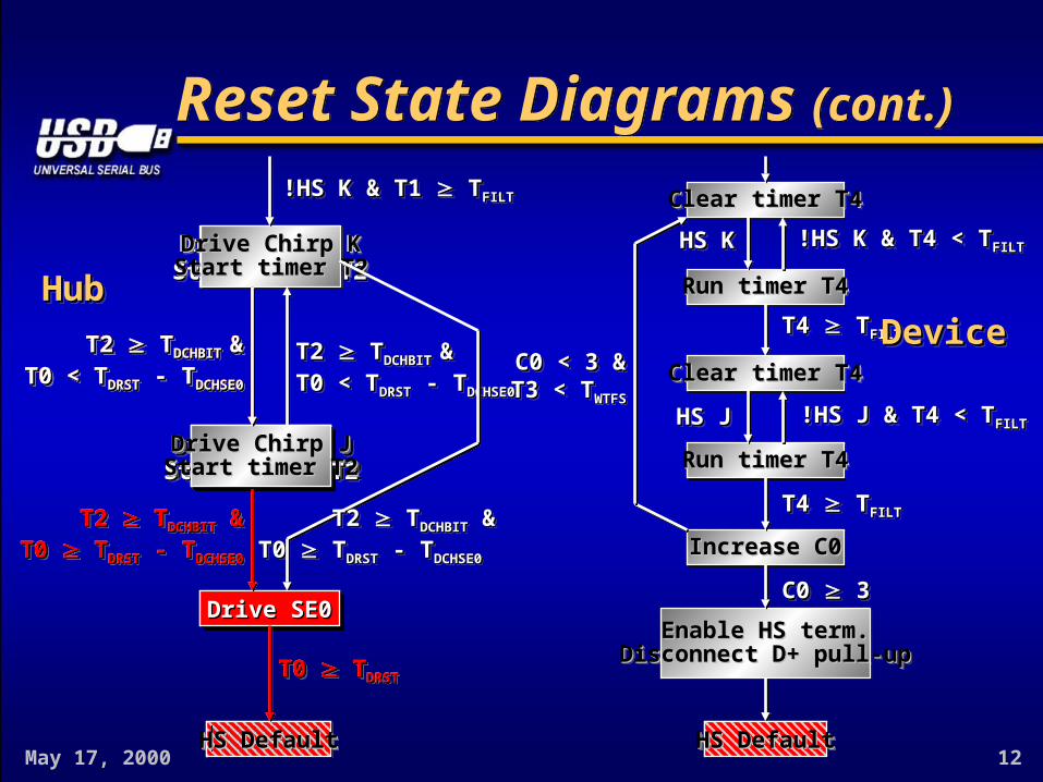
Reset State Diagrams (cont.)Reset State Diagrams (cont.)
HS DefaultHS DefaultHS DefaultHS Default
Increase C0Increase C0
Run timer T4Run timer T4
Clear timer T4Clear timer T4
Run timer T4Run timer T4
T4 T4 T TFILTFILTT4 T4 T TFILTFILT
T4 T4 T TFILTFILTT4 T4 T TFILTFILT
HS KHS KHS KHS K !HS K & T4 < T!HS K & T4 < TFILTFILT!HS K & T4 < T!HS K & T4 < TFILTFILT
HS JHS JHS JHS J !HS J & T4 < T!HS J & T4 < TFILTFILT!HS J & T4 < T!HS J & T4 < TFILTFILT
Enable HS term.Enable HS term.Disconnect D+ pull-upDisconnect D+ pull-up
Enable HS term.Enable HS term.Disconnect D+ pull-upDisconnect D+ pull-up
C0 < 3 &C0 < 3 &T3 < TT3 < TWTFSWTFS
C0 < 3 &C0 < 3 &T3 < TT3 < TWTFSWTFS
C0 C0 3 3C0 C0 3 3
HS DefaultHS DefaultHS DefaultHS Default
T0 T0 T TDRSTDRSTT0 T0 T TDRSTDRST
!HS K & T1 !HS K & T1 T TFILTFILT!HS K & T1 !HS K & T1 T TFILTFILT
Drive Chirp JStart timer T2Drive Chirp JStart timer T2
Drive SE0Drive SE0
T2 T2 T TDCHBITDCHBIT & &T0 T0 T TDRSTDRST - T - TDCHSE0DCHSE0
T2 T2 T TDCHBITDCHBIT & &T0 T0 T TDRSTDRST - T - TDCHSE0DCHSE0
T2 T2 T TDCHBITDCHBIT & & T0 T0 T TDRSTDRST - T - TDCHSE0DCHSE0
T2 T2 T TDCHBITDCHBIT & & T0 T0 T TDRSTDRST - T - TDCHSE0DCHSE0
T2 T2 T TDCHBIT DCHBIT &&T0 < TT0 < TDRSTDRST - T - TDCHSE0DCHSE0 T2 T2 T TDCHBIT DCHBIT &&T0 < TT0 < TDRSTDRST - T - TDCHSE0DCHSE0
T2 T2 T TDCHBIT DCHBIT &&T0 < TT0 < TDRSTDRST - T - TDCHSE0DCHSE0
T2 T2 T TDCHBIT DCHBIT &&T0 < TT0 < TDRSTDRST - T - TDCHSE0DCHSE0
DeviceDeviceDeviceDeviceHubHubHubHub
HS DefaultHS DefaultHS DefaultHS Default
Enable HS term.Enable HS term.Disconnect D+ pull-upDisconnect D+ pull-up
Enable HS term.Enable HS term.Disconnect D+ pull-upDisconnect D+ pull-up
C0 C0 3 3C0 C0 3 3
Increase C0Increase C0Increase C0Increase C0
Run timer T4Run timer T4Run timer T4Run timer T4
Clear timer T4Clear timer T4Clear timer T4Clear timer T4
Run timer T4Run timer T4Run timer T4Run timer T4
T4 T4 T TFILTFILTT4 T4 T TFILTFILT
T4 T4 T TFILTFILTT4 T4 T TFILTFILT
HS KHS KHS KHS K
HS JHS JHS JHS JDrive Chirp JDrive Chirp JStart timer T2Start timer T2Drive Chirp JDrive Chirp JStart timer T2Start timer T2
T2 T2 T TDCHBIT DCHBIT &&T0 < TT0 < TDRSTDRST - T - TDCHSE0DCHSE0
T2 T2 T TDCHBIT DCHBIT &&T0 < TT0 < TDRSTDRST - T - TDCHSE0DCHSE0 Clear timer T4Clear timer T4
Drive Chirp JStart timer T2Drive Chirp JStart timer T2
T2 T2 T TDCHBIT DCHBIT &&T0 < TT0 < TDRSTDRST - T - TDCHSE0DCHSE0 T2 T2 T TDCHBIT DCHBIT &&T0 < TT0 < TDRSTDRST - T - TDCHSE0DCHSE0
T4 T4 T TFILTFILTT4 T4 T TFILTFILT
T4 T4 T TFILTFILTT4 T4 T TFILTFILT
HS KHS KHS KHS K
HS JHS JHS JHS J
T2 T2 T TDCHBIT DCHBIT &&T0 < TT0 < TDRSTDRST - T - TDCHSE0DCHSE0
T2 T2 T TDCHBIT DCHBIT &&T0 < TT0 < TDRSTDRST - T - TDCHSE0DCHSE0
Increase C0Increase C0
Run timer T4Run timer T4
Run timer T4Run timer T4
May 17, 2000 12
Drive Chirp KDrive Chirp KStart timer T2Start timer T2Drive Chirp KDrive Chirp KStart timer T2Start timer T2Drive Chirp KDrive Chirp KStart timer T2Start timer T2Drive Chirp KDrive Chirp KStart timer T2Start timer T2
Reset State Diagrams (cont.)Reset State Diagrams (cont.)
HS DefaultHS DefaultHS DefaultHS Default
Clear timer T4Clear timer T4Clear timer T4Clear timer T4
Increase C0Increase C0Increase C0Increase C0
Run timer T4Run timer T4Run timer T4Run timer T4
Clear timer T4Clear timer T4Clear timer T4Clear timer T4
Run timer T4Run timer T4Run timer T4Run timer T4
T4 T4 T TFILTFILTT4 T4 T TFILTFILT
T4 T4 T TFILTFILTT4 T4 T TFILTFILT
HS KHS KHS KHS K !HS K & T4 < T!HS K & T4 < TFILTFILT!HS K & T4 < T!HS K & T4 < TFILTFILT
HS JHS JHS JHS J !HS J & T4 < T!HS J & T4 < TFILTFILT!HS J & T4 < T!HS J & T4 < TFILTFILT
Enable HS term.Enable HS term.Disconnect D+ pull-upDisconnect D+ pull-up
Enable HS term.Enable HS term.Disconnect D+ pull-upDisconnect D+ pull-up
C0 < 3 &C0 < 3 &T3 < TT3 < TWTFSWTFS
C0 < 3 &C0 < 3 &T3 < TT3 < TWTFSWTFS
C0 C0 3 3C0 C0 3 3
HS DefaultHS DefaultHS DefaultHS Default
T0 T0 T TDRSTDRSTT0 T0 T TDRSTDRST
!HS K & T1 !HS K & T1 T TFILTFILT!HS K & T1 !HS K & T1 T TFILTFILT
Drive Chirp JDrive Chirp JStart timer T2Start timer T2Drive Chirp JDrive Chirp JStart timer T2Start timer T2
Drive SE0Drive SE0Drive SE0Drive SE0
T2 T2 T TDCHBITDCHBIT & &T0 T0 T TDRSTDRST - T - TDCHSE0DCHSE0
T2 T2 T TDCHBITDCHBIT & &T0 T0 T TDRSTDRST - T - TDCHSE0DCHSE0
T2 T2 T TDCHBITDCHBIT & & T0 T0 T TDRSTDRST - T - TDCHSE0DCHSE0
T2 T2 T TDCHBITDCHBIT & & T0 T0 T TDRSTDRST - T - TDCHSE0DCHSE0
T2 T2 T TDCHBIT DCHBIT &&T0 < TT0 < TDRSTDRST - T - TDCHSE0DCHSE0 T2 T2 T TDCHBIT DCHBIT &&T0 < TT0 < TDRSTDRST - T - TDCHSE0DCHSE0
T2 T2 T TDCHBIT DCHBIT &&T0 < TT0 < TDRSTDRST - T - TDCHSE0DCHSE0
T2 T2 T TDCHBIT DCHBIT &&T0 < TT0 < TDRSTDRST - T - TDCHSE0DCHSE0
DeviceDeviceDeviceDeviceHubHubHubHub
HS DefaultHS DefaultHS DefaultHS Default
Drive SE0Drive SE0Drive SE0Drive SE0
T0 T0 T TDRSTDRSTT0 T0 T TDRSTDRST
T2 T2 T TDCHBITDCHBIT & & T0 T0 T TDRSTDRST - T - TDCHSE0DCHSE0
T2 T2 T TDCHBITDCHBIT & & T0 T0 T TDRSTDRST - T - TDCHSE0DCHSE0
Drive Chirp JDrive Chirp JStart timer T2Start timer T2Drive Chirp JDrive Chirp JStart timer T2Start timer T2
T2 T2 T TDCHBIT DCHBIT &&T0 < TT0 < TDRSTDRST - T - TDCHSE0DCHSE0
T2 T2 T TDCHBIT DCHBIT &&T0 < TT0 < TDRSTDRST - T - TDCHSE0DCHSE0
Drive Chirp JDrive Chirp JStart timer T2Start timer T2Drive Chirp JDrive Chirp JStart timer T2Start timer T2
T2 T2 T TDCHBIT DCHBIT &&T0 < TT0 < TDRSTDRST - T - TDCHSE0DCHSE0
T2 T2 T TDCHBIT DCHBIT &&T0 < TT0 < TDRSTDRST - T - TDCHSE0DCHSE0
HS DefaultHS DefaultHS DefaultHS Default
May 17, 2000 13
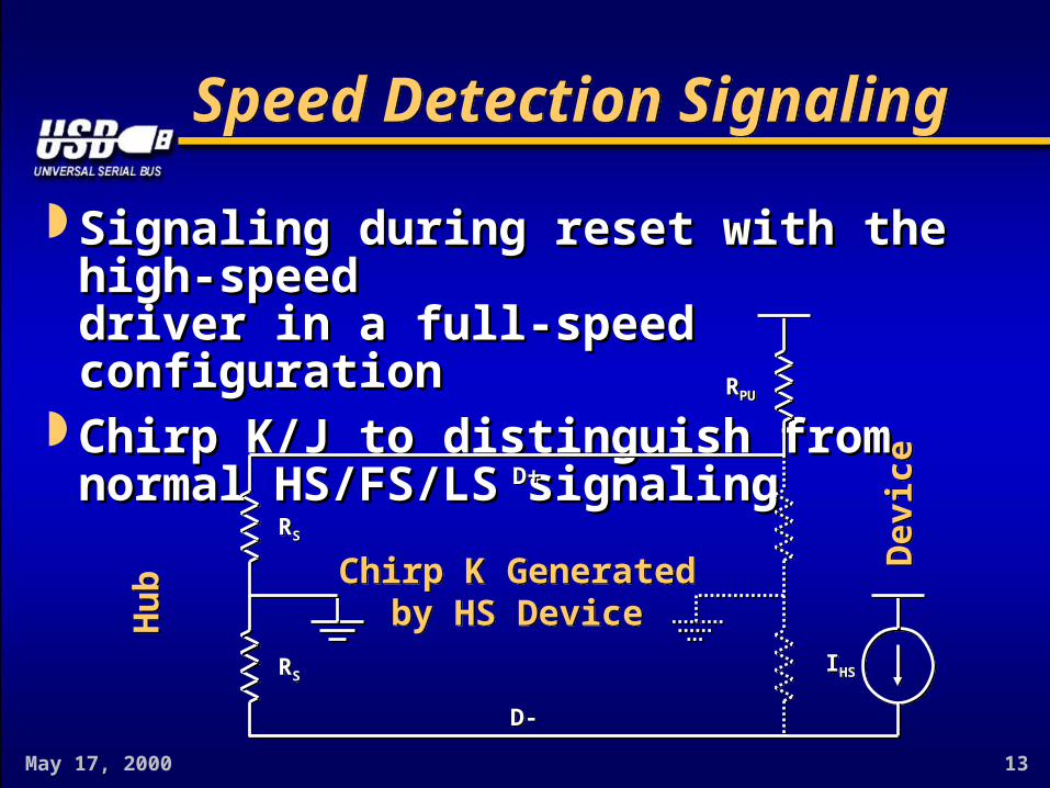
Speed Detection SignalingSpeed Detection Signaling
Signaling during reset with the high-speedSignaling during reset with the high-speeddriver in a full-speed configurationdriver in a full-speed configuration
Chirp K/J to distinguish fromChirp K/J to distinguish fromnormal HS/FS/LS signalingnormal HS/FS/LS signaling
Chirp K Generatedby HS Device
Chirp K Generatedby HS Device
D+D+
D-D-
RSRS
RSRS
RPURPU
IHSIHS
Dev
ice
Dev
ice
HubHub

May 17, 2000 14
Speed Detection Signaling (cont.)Speed Detection Signaling (cont.)
Chirp KChirp K : -0.9 – -0.5 V (differential): -0.9 – -0.5 V (differential) Chirp JChirp J : 0.7 – 1.1 V (differential): 0.7 – 1.1 V (differential)
Chirp K GeneratedChirp K Generatedby HS Hubby HS Hub
Chirp K GeneratedChirp K Generatedby HS Hubby HS Hub
D+D+D+D+
D-D-D-D-
RRSSRRSS
RRSSRRSS
RRPUPURRPUPU
IIHSHSIIHSHS
Dev
ice
Dev
ice
Dev
ice
Dev
iceH
ubHub
HubHub

May 17, 2000 15
ImplementationImplementation
Implementation of Reset Protocol:Implementation of Reset Protocol:– Requires very few additional gatesRequires very few additional gates– Has very loose timing requirementsHas very loose timing requirements
(system clock not required!) (system clock not required!)– Does not require logic at serial clock rateDoes not require logic at serial clock rate
(possible at parallel interface) (possible at parallel interface) Result: Reset Protocol can be implementedResult: Reset Protocol can be implemented
in many different waysin many different ways– Hardware, software, firmware, digital, analog, etc.Hardware, software, firmware, digital, analog, etc.

May 17, 2000 16
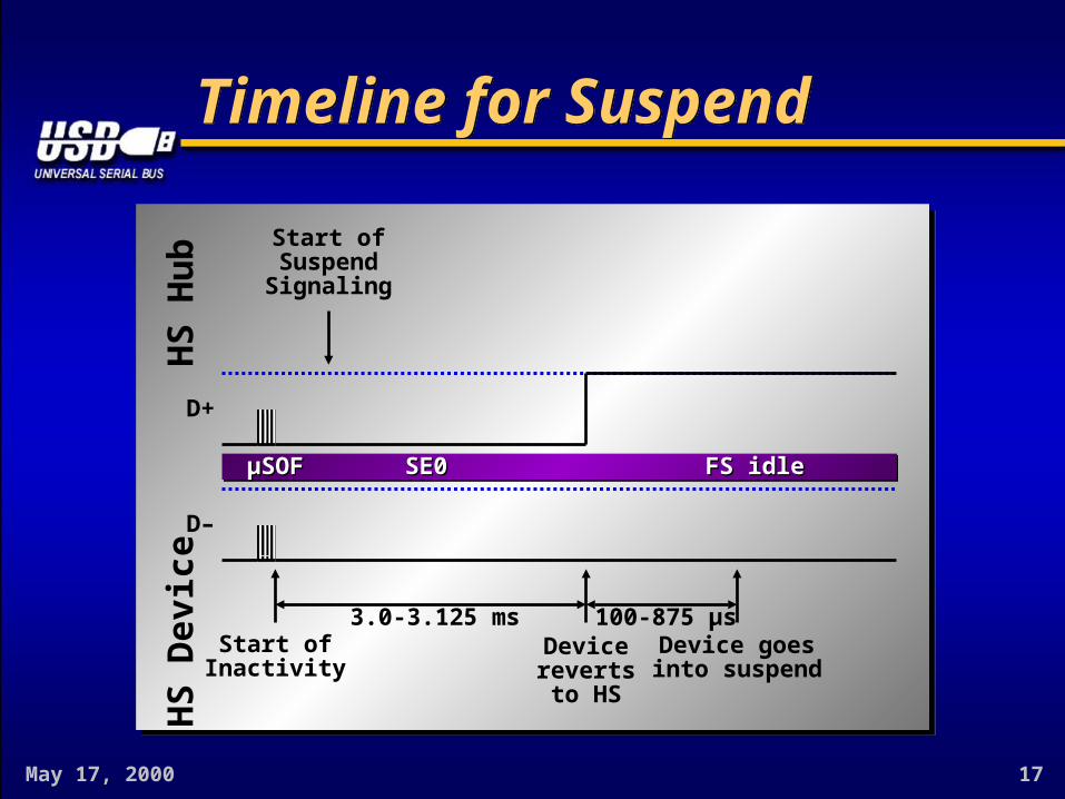
SuspendSuspend
High-speed idle is identical to SE0High-speed idle is identical to SE0– Suspend initially indistinguishable from resetSuspend initially indistinguishable from reset
Only after reverting to full-speed a HS deviceOnly after reverting to full-speed a HS devicecan make the distinction between idle and SE0can make the distinction between idle and SE0
May 17, 2000 17
Timeline for SuspendTimeline for Suspend
FS idleFS idleSE0SE0
100-875 μs3.0-3.125 msDevicerevertsto HS
Start ofInactivity
μSOFμSOF
HS
Hub
HS
Dev
ice
D–
D+
Device goesinto suspend
Start ofSuspendSignaling
May 17, 2000 18
Reset from SuspendReset from Suspend
Reset of a suspended device should wake upReset of a suspended device should wake upthat device from suspendthat device from suspend
Low-power consumption makes fast start-upLow-power consumption makes fast start-upfrom suspend a challengefrom suspend a challenge– No HS clock, no current referenceNo HS clock, no current reference
Reset protocol designed to do all handshakeReset protocol designed to do all handshakesignaling without a stable clocksignaling without a stable clock– Very relaxed timing and voltage specsVery relaxed timing and voltage specs
Do not use the single-ended FS receivers for this!Do not use the single-ended FS receivers for this!

May 17, 2000 19
Timeline for Resetfrom SuspendTimeline for Resetfrom Suspend
FS idleFS idle Device ChirpDevice Chirp Hub ChirpHub Chirp
D–
> 2.5 μs < 500 μs> 1.0 ms
< 7.0 ms
< 100 μs 100-500 μs> 10 ms
End ofDevice ChirpStart of
Device Chirp
Start ofReset
Devicerevertsto HS
Devicedetects
Hub Chirp
Start ofReset
End ofReset
End ofHub Chirp
Start ofHub Chirp
μSOFμSOF
HS
Hub
D+
HS
Dev
ice
SE0SE0 SE0SE0 HS idleHS idleSE0SE0

May 17, 2000 20
ResumeResume
High-speed devices that were suspended fromHigh-speed devices that were suspended fromhigh-speed operation resume to high-speedhigh-speed operation resume to high-speed
No need for high-speed capability detectionNo need for high-speed capability detectionduring resume signalingduring resume signaling
May 17, 2000 21
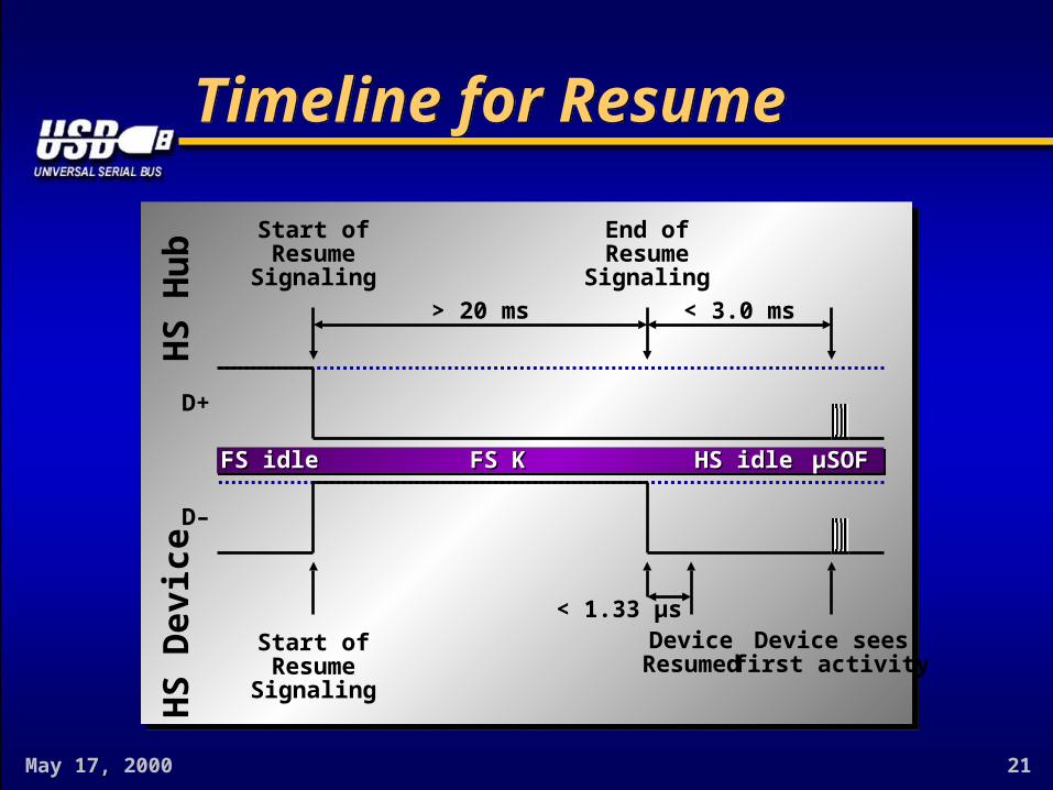
Timeline for ResumeTimeline for Resume
< 3.0 ms
End ofResume
Signaling
Start ofResume
Signaling
HS
Hub
HS
Dev
ice
FS KFS K HS idleHS idle μSOFμSOF
D+
Device seesfirst activity
Start ofResume
Signaling
D–
FS idleFS idle
> 20 ms
DeviceResumed
< 1.33 μs

May 17, 2000 22
USB 2.0 High-Speed Eye Pattern Templates
USB 2.0 High-Speed Eye Pattern Templates

May 17, 2000 23
Transmitter EyePattern TemplatesTransmitter EyePattern Templates
These templates govern the output waveforms at These templates govern the output waveforms at various test planesvarious test planes
Waveforms are specified for a transmitter drivingWaveforms are specified for a transmitter drivinga reference test fixturea reference test fixture
Waveforms do not specify actual signals observedWaveforms do not specify actual signals observedon a USB linkon a USB link
VbusVbus
D+ D+
D- D-
GndGnd
VbusVbus
D+ D+
D- D-
GndGnd
15.8 Ohms15.8 Ohms ++To 50 Ohm Inputs of aTo 50 Ohm Inputs of aHigh Speed DifferentialHigh Speed Differential
Oscilloscope, or 50 OhmOscilloscope, or 50 Ohm Outputs of a High Speed Outputs of a High Speed
Differential Data Generator Differential Data Generator
--
50 Ohm50 OhmCoaxCoax
““A”A”PlugPlug
N.C.N.C.
15.8 Ohms15.8 Ohms
143143OhmsOhms
143143OhmsOhms
50 Ohm50 OhmCoaxCoax
May 17, 2000 24
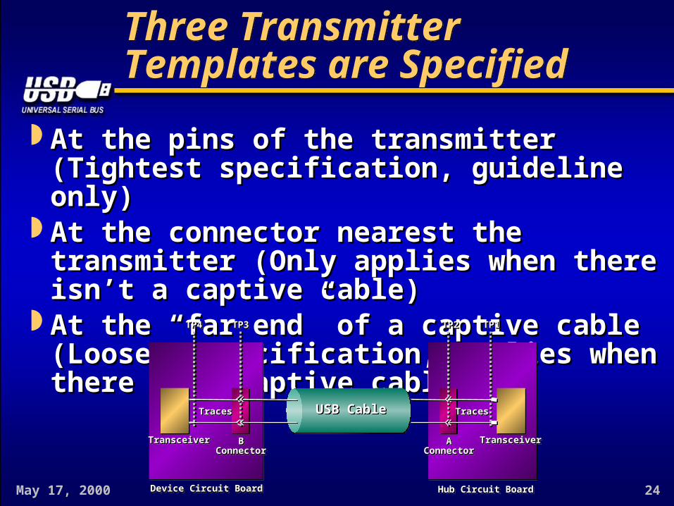
Three Transmitter Templates are SpecifiedThree Transmitter Templates are Specified
At the pins of the transmitter (Tightest specification, At the pins of the transmitter (Tightest specification, guideline only)guideline only)
At the connector nearest the transmitter (Only applies At the connector nearest the transmitter (Only applies when there isn’t a captive cable)when there isn’t a captive cable)
At the “far end” of a captive cable (Loosest At the “far end” of a captive cable (Loosest specification, applies when there is a captive cable)specification, applies when there is a captive cable)
USB CableUSB CableUSB CableUSB Cable
Device Circuit BoardDevice Circuit BoardDevice Circuit BoardDevice Circuit Board Hub Circuit BoardHub Circuit BoardHub Circuit BoardHub Circuit Board
AAConnectorConnector
AAConnectorConnector
TracesTracesTracesTraces TracesTracesTracesTraces
TransceiverTransceiverTransceiverTransceiver TransceiverTransceiverTransceiverTransceiver
TP4TP4TP4TP4 TP3TP3TP3TP3 TP2TP2TP2TP2 TP1TP1TP1TP1
BBConnectorConnector
BBConnectorConnector

May 17, 2000 25
Example of a “Passing” Transmitter WaveformExample of a “Passing” Transmitter Waveform
Note that higher level of overshoot is allowed in Note that higher level of overshoot is allowed in the unit interval following a transitionthe unit interval following a transition
May 17, 2000 26
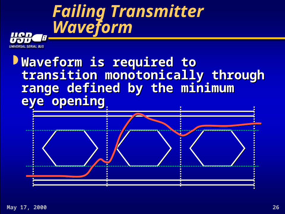
Failing Transmitter WaveformFailing Transmitter Waveform
Waveform is required to transition monotonically Waveform is required to transition monotonically through range defined by the minimumthrough range defined by the minimumeye openingeye opening
May 17, 2000 27
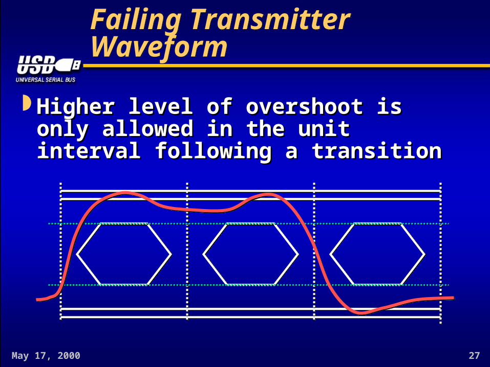
Failing Transmitter WaveformFailing Transmitter Waveform
Higher level of overshoot is only allowed in the Higher level of overshoot is only allowed in the unit interval following a transitionunit interval following a transition

May 17, 2000 28
Narrow/Wide Symbols are Allowed as Long as they Conform to the TemplateNarrow/Wide Symbols are Allowed as Long as they Conform to the Template

May 17, 2000 29
Receiver Sensitivity TemplatesReceiver Sensitivity Templates
Receiver templates are never actually measuredReceiver templates are never actually measured These templates define the worst case allowable These templates define the worst case allowable
waveforms that a receiver is required to recoverwaveforms that a receiver is required to recover Actual waveforms at specified planes will be Actual waveforms at specified planes will be
better than the receiver templatesbetter than the receiver templates
May 17, 2000 30
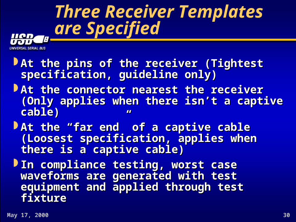
Three Receiver Templates are SpecifiedThree Receiver Templates are Specified
At the pins of the receiver (Tightest specification, At the pins of the receiver (Tightest specification, guideline only)guideline only)
At the connector nearest the receiver (Only applies At the connector nearest the receiver (Only applies when there isn’t a captive cable)when there isn’t a captive cable)
At the “far end” of a captive cable (Loosest At the “far end” of a captive cable (Loosest specification, applies when there is a captive cable)specification, applies when there is a captive cable)
In compliance testing, worst case waveforms are In compliance testing, worst case waveforms are generated with test equipment and applied through generated with test equipment and applied through test fixturetest fixture

May 17, 2000 31
How Is an Eye Pattern Measured?How Is an Eye Pattern Measured?
1.1. The entire Test Packet waveform is capturedThe entire Test Packet waveform is capturedwith a single-shot transient capture instrumentwith a single-shot transient capture instrument
2.2. The “best fit” frequency and delay are computed The “best fit” frequency and delay are computed for the zero crossings in the record (bounded by for the zero crossings in the record (bounded by the allowed frequency range of +/- 500 ppm) the allowed frequency range of +/- 500 ppm)
3.3. The record is scanned for overshoot and The record is scanned for overshoot and monotonicity violationsmonotonicity violations
May 17, 2000 32
How Is an Eye Pattern Measured? (cont.)How Is an Eye Pattern Measured? (cont.)
1.1. The unit intervals are “cut” and “superimposed”The unit intervals are “cut” and “superimposed”to produce the aggregate eye patternto produce the aggregate eye pattern
2.2. The aggregate pattern is examined forThe aggregate pattern is examined fortemplate violationstemplate violations


![Assetz Marq Bangalore[[9019196393]]New Launch Whitefield](https://static.fdocuments.us/doc/165x107/56816698550346895dda82f7/assetz-marq-bangalore9019196393new-launch-whitefield.jpg)

