Maximum Precision for Every Movement RA-EA/EC solid shaft gears for tool magazine and tool-changing...
32
Maximum Precision for Every Movement
Transcript of Maximum Precision for Every Movement RA-EA/EC solid shaft gears for tool magazine and tool-changing...

Nabtesco Precision Europe GmbHKlosterstrasse 4940211 DüsseldorfGermany
Tel. : +49 (0) 211 173 79 0Fax: +49 (0) 211 364 677E-mail: [email protected]
Precision is born of experienceNabtesco Precision is the world’s largest manufac-turer of high-performance eccentric gears, and is part of the Nabtesco Group. Precision reduction gears developed by Nabtesco Precision are used by over 60% of all industrial robots worldwide. The reason is that our products are designed for maximum precision and load-bearing capacity and, consequently, are ideal for all applications requiring precise and powerful movements. We are always close to our customers, thanks to numerous production, service and sales locations. Over 4.500 employees around the world ensure that finely tuned quality is achieved for every individual gear.
11 /2
012
– S
peci
fi cat
ions
are
sub
ject
to c
hang
e w
ithou
t not
ice
– w
ww
.moo
n-ag
entu
r.de
Maximum Precision for Every Movement
C
M
Y
CM
MY
CY
CMY
K
Nabtesco Umschlag Stanze.pdf 10.11.2011 15:47:17 Uhr
NAB_2012_Uebersichtsbr_230x315_RZ_11-2012.indd 2-3 12.11.12 11:58

02|
RV-C Hollow shaftT up to 11.760 Nmi up to 283
NAB_2012_Uebersichtsbr_230x315_RZ_11-2012.indd 4-5 12.11.12 11:58

Page 4 Technology & advantages
6 Component sets
8 RV-E solid shaft
10 RV-C hollow shaft
12 RV solid shaft without bearing support
14 Gearheads
16 RD_-E solid shaft
18 RD_-C hollow shaft
20 GH for high output speeds
22 Special gears for machine tools
24 RA-EA/EC solid shaft gears for tool magazine and tool-changing systems
26 NT hollow shaft gears for NC rotary tables
28 Applications
30 Input shaft / pinion
Contents
The Best Choice for Precision Movement and a High Level of Energy Effi ciency
Two extremes must be harmonised when it comes to machine and plant construction, particularly in the area of robotics and the machine tool industry: high torques and high reduction ratios. Precision gears from Nabtesco Precision represent the ideal solution in this respect. The crankshaft cam technology em- ployed means that Nabtesco gears can withstand extremely high accelerating forces and torques. This simultaneously enables the achievement of move-ments and positioning characterised by maximum precision.
Our eccentric gears realise these characteristics in the most confi ned installation spaces, making them optimum components for versatile operational areas and innovative applications, such as in medical technology, high-end machine tools, solar technol-ogy, handling applications and much more. Nabtesco Precision Europe GmbH, part of the Nabtesco Group, is the world’s largest and most widely recognised manufacturer of precision gears.
Internationally successful• over 60% of all industrial robots use Nabtesco gears• more than 4.000.000 RV gears are in use• individual customer service worldwide• over 30 years of development and design experience• maximum production and service quality• efficiency level up to 85%
Nabtesco gears achieve an effi ciency level of up to 85%
About Nabtesco |03
85%85%85%85%85%85%Effic
ient Motion Control
efficiency level
NAB_2012_Uebersichtsbr_230x315_RZ.indd 6 10.05.12 15:16


Eccentric Gears Offer Unbeatable Advantages
The two-stage reduction of eccentric gears makes solutions from Nabtesco Precision so successful. The reason is that the speed is reduced by the double cams. Vibration is reduced by the two-stage reduction principle and low inertia. The force is also distributed very evenly, thanks to the roller cam design, and this contributes to the minimum hysteresis loss and enormous resistance to shock loading. Consequently, eccentric gears are as versatile as they are resilient.
Mode of operation of eccentric gearboxesThe drive or servomotor is connected to the spur gear stage of the gearbox via a pinion. The rotating speed reduces at this point relative to the reduction ratio between the pinion and planetary gear. The planetary gears are connected to crankshafts which drive the cams using needle bearings. These cams rotate inside the case which is lined with pins.
The cam has exactly one eccentric section less than the pin ring has pins. A 360° revolution of the crank-shafts therefore causes the cams to rotate one pin farther, whereby practically all the gear teeth are in continuous contact with the pins. The rotating move- ment is then transmitted from the input shaft to the crankshafts via the spur gear stage, and these then shift the cams in the pin ring and, consequently, gen- erate a reduced speed with high precision. This tech- nology enables the RV gears to absorb fi ve times the rated torque in emergency-stop situations without suffering any damage.
The resulting overall reduction is the same as the product of the two reduction ratios (spur gear stage and eccentric stage).
RV-E Solid shaftT up to 14.715 Nmi up to 257
RV gear
Crankshaft
Eccentricstage
Spur gear
Needle bearing
Rotation angle Crankshaft 180°
Case Crankshaft(Connected to the spur gear)
ShaftRV gearPin
Rotation angle Crankshaft 0°
Rotation angle Crankshaft 360°
Technology & advantages |05
NAB_2012_Uebersichtsbr_230x315_RZ.indd 8 10.05.12 15:16

06|
Nabtesco Precision component sets are, essentially, available in three versions:• The RV series is the basic version and can be com-
bined with different output supports.• RV-E solid shaft gears provide high reduction ratios
and are extremely resilient, thanks to integrated angular bearings.
• The identical RV-C series has a hollow shaft with a diameter of up to 138 mm which, for example, facilitates the routing of data and power supply cables and integrated output shaft support.
Component Sets
Main areas of application
• Robotics• Machine tools• Packaging machinery • Medical technology
• Handling applications• Positioning• Antenna systems• Woodworking machinery
85%85%85%85%85%85%Effic
ient Motion Control
efficiency levelRV-E Page 8
RV-C Page 10
RV Page 12
T 58 – 14.715 Nm | i 31 – 257
T 98 – 11.760 Nm | i 27 – 283
T 137 – 5.390 Nm | i 57 – 192,4
NAB_2012_Uebersichtsbr_230x315_RZ.indd 9 10.05.12 15:16

RV 80 121 BAE
RV-C Hollow shaftT up to 11.760 Nmi up to 283
Type designation
Type designation
Size E = solid shaftC = hollow shaftwithout = original type (no output shaft support)
Ratio Output shaft: Mounting method
B = boltsP = bolts &
tapered pinsT = through bolts
Input shaft
A = narrow shaft end (standard)
B = wide shaft end (standard)
Z = customised
Component sets |07
NAB_2012_Uebersichtsbr_230x315_RZ.indd 10 10.05.12 15:16

08|
Areas of use
• Robotics• Machine tools• Positioning• Palletising
RV-E Component Sets – Solid Shaft
The RV-E series is extremely versatile, providing the advantages of high reduction ratios and minimum space requirements. RV-E gears operate with max -imum reliability and precision, thanks to high torsional and tilting rigidity. The integrated angular bearings additionally minimise the outlay for installation and extension of the service life.
Advantages• high torque and minimum installation space
requirements• high shock-load capability
(up to 5 times the rated torque)• high rigidity• high precision (hysteresis loss < 1 arcmin)• less vibration• low inertia• integrated angular bearings
low wear longer service life low breakaway torque high efficiency
Areas of use
NAB_2012_Uebersichtsbr_230x315_RZ.indd 11 10.05.12 15:16
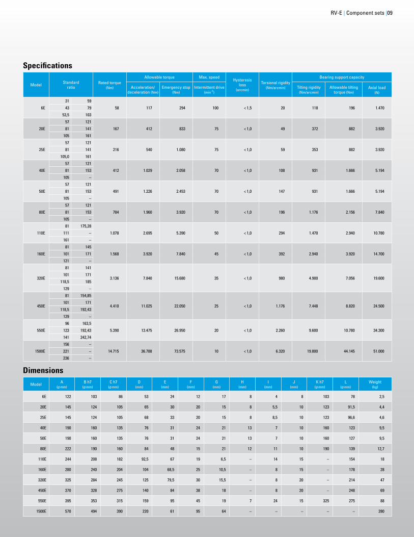
Dimensions
Model Standard ratio
Rated torque (Nm)
Allowable torque Max. speedHysteresis
loss (arcmin)
Torsional rigidity (Nm/arcmin)
Bearing support capacity
Acceleration/deceleration (Nm)
Emergency stop (Nm)
Intermittent drive (min-1)
Tilting rigidity (Nm/arcmin)
Allowable tilting torque (Nm)
Axial load(N)
6E
31 59
58 117 294 100 < 1,5 20 118 196 1.47043 79
53,5 103
20E
57 121
167 412 833 75 < 1,0 49 372 882 3.92081 141
105 161
25E
57 121
216 540 1.080 75 < 1,0 59 353 882 3.92081 141
105,0 161
40E
57 121
412 1.029 2.058 70 < 1,0 108 931 1.666 5.19481 153
105 –
50E
57 121
491 1.226 2.453 70 < 1,0 147 931 1.666 5.19481 153
105 –
80E
57 121
784 1.960 3.920 70 < 1,0 196 1.176 2.156 7.84081 153
105 –
110E
81 175,28
1.078 2.695 5.390 50 < 1,0 294 1.470 2.940 10.780111 –
161 –
160E
81 145
1.568 3.920 7.840 45 < 1,0 392 2.940 3.920 14.700101 171
121 –
320E
81 141
3.136 7.840 15.680 35 < 1,0 980 4.900 7.056 19.600101 171
118,5 185
129 –
450E
81 154,85
4.410 11.025 22.050 25 < 1,0 1.176 7.448 8.820 24.500101 171
118,5 192,43
129 –
550E
96 163,5
5.390 13.475 26.950 20 < 1,0 2.260 9.600 10.780 34.300123 192,43
141 242,74
1500E
156 –
14.715 36.788 73.575 10 < 1,0 6.320 19.800 44.145 51.000221 –
236 –
Model A ( mm)
B h7( mm)
C h7( mm)
D(mm)
E(mm)
F(mm)
G(mm)
H(mm)
I(mm)
J(mm)
K h7( mm)
L( mm)
Weight (kg)
6E 122 103 86 53 24 12 17 8 4 8 103 78 2,5
20E 145 124 105 65 30 20 15 8 5,5 10 123 91,5 4,4
25E 145 124 105 68 33 20 15 8 8,5 10 123 96,6 4,6
40E 190 160 135 76 31 24 21 13 7 10 160 123 9,5
50E 190 160 135 76 31 24 21 13 7 10 160 127 9,5
80E 222 190 160 84 48 15 21 12 11 10 190 139 12,7
110E 244 208 182 92,5 67 19 6,5 – 14 15 – 154 18
160E 280 240 204 104 68,5 25 10,5 – 8 15 – 178 28
320E 325 284 245 125 79,5 30 15,5 – 8 20 – 214 47
450E 370 328 275 140 84 38 18 – 8 20 – 248 69
550E 395 353 315 159 95 45 19 7 24 15 325 275 88
1500E 570 494 390 220 61 95 64 – – – – – 280
Specifications
RV-E | Component sets |09
NAB_2012_Uebersichtsbr_230x315_RZ.indd 12 10.05.12 15:16

10|
Areas of use
• 5-axis pivoting heads (CNC) • Robotics• Medical technology• Antenna systems
RV-CComponent Sets – Hollow Shaft
RV-C gears have a hollow shaft through which power supply cables, drive shafts, etc. can be fed. Their design is otherwise identical to that of the RV-E series. RV-C component sets are therefore just as compact and effi cient as RV-E gears.
Advantages• hollow shaft (for routing cables, etc.)• high torque and minimum installation space
requirements• high shock-load capability
(up to 5 times the rated torque)• high rigidity• high precision (hysteresis loss < 1 arcmin)• less vibration• low inertia• integrated angular bearings
low wear longer service life low breakaway torque high efficiencyAreas of use
• 5-axis pivoting heads (CNC)
NAB_2012_Uebersichtsbr_230x315_RZ.indd 13 10.05.12 15:16

Model Standard ratio
Rated torque (Nm)
Allowable torque Max. speedHysteresis
loss (arcmin)
Torsional rigidity (Nm/arcmin)
Bearing support capacity
Acceleration/deceleration (Nm)
Emergency stop (Nm)
Intermittent drive (min-1)
Tilting rigidity (Nm/arcmin)
Allowable tilting torque (Nm)
Axial load(N)
10C 27 98 245 490 80 < 1,0 47 421 686 5.880
27C36,57
(1,390/38)265 662 1.323 55 < 1,0 163 1.068 980 8.820
50C32,54
(1,985/61)490 1.225 2.450 50 < 1,0 255 1.960 1.764 11.760
100C 36,75 980 2.450 4.900 40 < 1,0 510 2.813 2.450 13.720
155C 33,62 1.470 3.675 7.350 30 < 1,0 735 4.900 7.056 15.680
200C34,86
(1,499/43)1.961 4.900 9.800 30 < 1,0 980 9.800 8.820 19.600
320C35,61
(2,778/78)3.136 7.840 15.680 25 < 1,0 1.960 12.740 20.580 29.400
400C35,61
(2,778/78)3.920 9.800 19.600 20 < 1,0 2.450 19.600 24.500 34.300
500C37,34
(3,099/83)4.900 12.250 24.500 20 < 1,0 3.430 24.500 34.300 39.200
900C 42,84 8.820 22.050 44.100 15 < 1,0 4.900 34.300 44.150 51.000
1200C 42,84 11.760 29.400 58.800 12 < 1,0 5.880 34.300 44.150 51.000
Model A( mm)
B h7( mm)
C H7( mm)
D( mm)
E(mm)
F(mm)
G(mm)
H(mm)
I Weight (kg)
10C 147 110 34 31 4 49,5 17 19,2 6807 4,6
27C 182 140 47 43 5 57,5 16,6 19,5 6810 8,5
50C 222,5 176 66 57 5 68 20,2 23,8 6813 15
100C 250,5 199 73 71 5 72,6 19,9 21,15 6816 19,5
155C 293 234 90 80,5 6 104,5 29,1 33 6818 37
200C 347 260 100 90 7 102 31,2 33,2 6820 57
320C 440 340 140 138 5,5 101 38 43,5 6830 80
400C 485 350 140 138 6 110,5 39 43,5 6830 108
500C 520 390 150 138 7,5 130,5 47,5 50 6832 160
900C 543 390 135 – 22,5 144 80,8 82,6 6828 225
1200C 570 490 135 – – 136 105 – 6828 235
Specifications
Dimensions
RV-C | Component sets |11
NAB_2012_Uebersichtsbr_230x315_RZ.indd 14 10.05.12 15:16

12|
A
Areas of use
• Robotics• Machine tools• Positioning• Palletising• Solar technology
RV Component Sets – Solid Shaft without Bearing Support
The RV series is the basic version of our precision gears. It enables the achievement of high reduction ratios. As the force is transmitted via rollers, RV gears are characterised by higher precision and low hystere sis loss. RV gears are especially compact, thanks to the external bearing support, and are capable of determining the output support themselves. This makes them the ideal solution for integrated applications which exactly refl ect your specifi cations.
Advantages• extremely compact design• external output support (freely selectable)• high torque• high shock-load capability (up to 5 times the rated
torque)• high rigidity• high precision (hysteresis loss < 1 arcmin)• less vibration• low inertia
Areas of use
• Robotics• Machine tools
extremely compact design• external output support (freely selectable)• high torque• high shock-load capability (up to 5 times the rated
torque)• high rigidity• high precision (hysteresis loss < 1 arcmin)• less vibration• low inertia
NAB_2012_Uebersichtsbr_230x315_RZ.indd 15 10.05.12 15:17
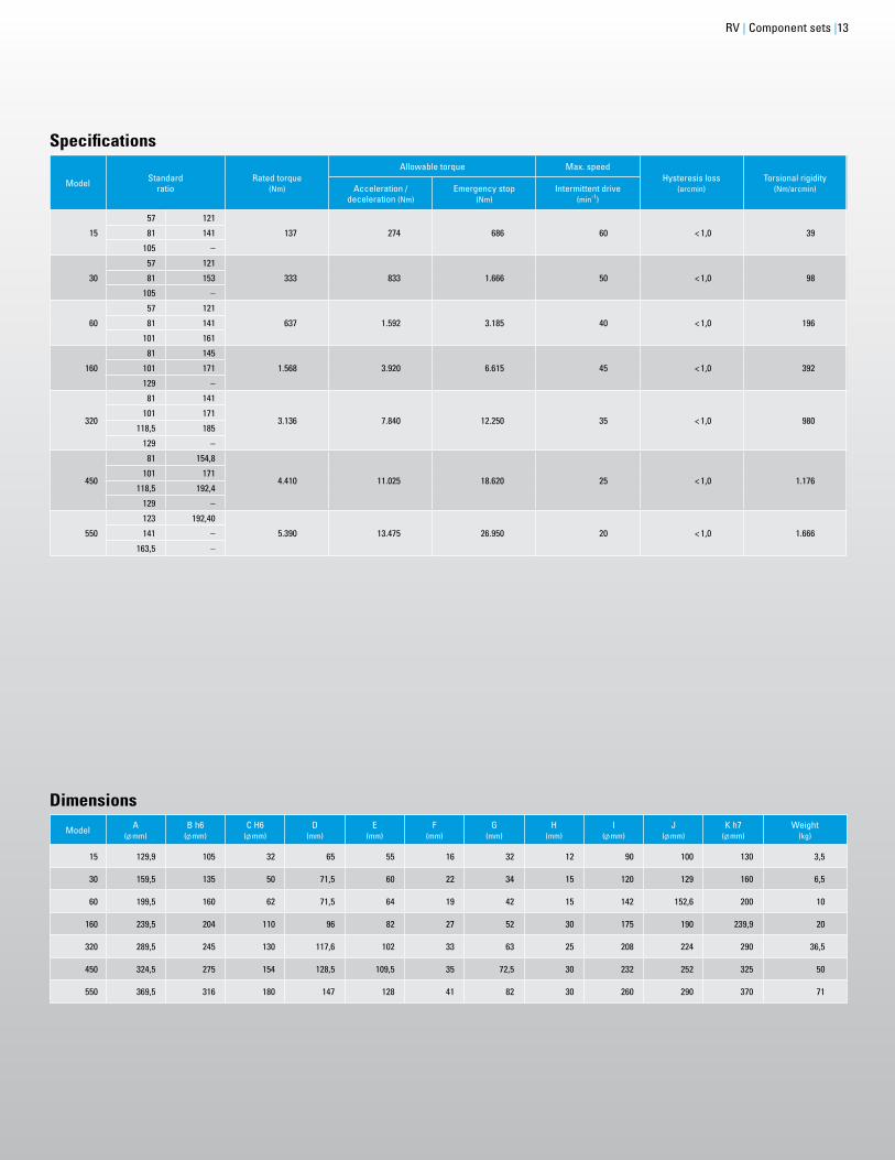
Model Standard ratio
Rated torque (Nm)
Allowable torque Max. speedHysteresis loss
(arcmin)Torsional rigidity
(Nm/arcmin)Acceleration / deceleration (Nm)
Emergency stop (Nm)
Intermittent drive (min-1)
15
57 121
137 274 686 60 < 1,0 3981 141
105 –
30
57 121
333 833 1.666 50 < 1,0 9881 153
105 –
60
57 121
637 1.592 3.185 40 < 1,0 19681 141
101 161
160
81 145
1.568 3.920 6.615 45 < 1,0 392101 171
129 –
320
81 141
3.136 7.840 12.250 35 < 1,0 980101 171
118,5 185
129 –
450
81 154,8
4.410 11.025 18.620 25 < 1,0 1.176101 171
118,5 192,4
129 –
550
123 192,40
5.390 13.475 26.950 20 < 1,0 1.666141 –
163,5 –
Model A( mm)
B h6( mm)
C H6( mm)
D(mm)
E(mm)
F(mm)
G(mm)
H(mm)
I( mm)
J( mm)
K h7( mm)
Weight (kg)
15 129,9 105 32 65 55 16 32 12 90 100 130 3,5
30 159,5 135 50 71,5 60 22 34 15 120 129 160 6,5
60 199,5 160 62 71,5 64 19 42 15 142 152,6 200 10
160 239,5 204 110 96 82 27 52 30 175 190 239,9 20
320 289,5 245 130 117,6 102 33 63 25 208 224 290 36,5
450 324,5 275 154 128,5 109,5 35 72,5 30 232 252 325 50
550 369,5 316 180 147 128 41 82 30 260 290 370 71
Specifications
Dimensions
RV | Component sets |13
NAB_2012_Uebersichtsbr_230x315_RZ.indd 16 10.05.12 15:17

14|
The ready-to-install solution from Nabtesco: com-pletely enclosed gearheads fi lled with lubricant and sealed tightly through encapsulation. The gear-heads can absorb very high forces, thanks to the integrated angular bearings. An additional output bearing is generally unnecessary.
All gearheads have an integrated adapter plate for the motor and a motor shaft coupling for servomotors. This enables you to reduce the time required for construction and installation.
Gearheads
Main areas of application
• Robotics• Machine tools• Packaging machinery • Medical technology
• Handling applications• Positioning• Antenna systems• Woodworking machinery
RD_-E Page 16
RD_-C Page 18
GH Page 20T 69 – 980 Nm | i 10,7436 – 31,4348 | n 150 min-1
T 58 – 3.136 Nm | i 31 – 185
T 98 – 3.136 Nm | i 81 – 258
NAB_2012_Uebersichtsbr_230x315_RZ.indd 17 10.05.12 16:00

RD
GH
160S
24
101
A
JB 4D
P
B5
B
E
31
RD-C Hollow shaftT up to 3.136 Nmi up to 258
Type designation
Type designation
Type designation
Size
Size
E = solid shaftC = hollow shaft
Ratio
Ratio
Input shaft
Motor fl ange Bushing
Mounting methodP = fl ange typeS = shaft type
Motor coupling
Motor fl ange
Gearheads |15
InputS = straightR = right angleP = pulley
NAB_2012_Uebersichtsbr_230x315_RZ.indd 18 10.05.12 15:17

16|
Areas of use
• Machine tools• Positioning• Palletising• Solar technology
RD_-E Gearheads –Solid Shaft
The gearheads of the new RD2-E series are more compact and versatile than ever. Three different models allow for numerous types of use, e.g. in servomotors. The gearheads are entirely enclosed, are pre-fi lled with lubricants ex-works and ready for immediate installation. A high-precision, extremely resistant and extra durable, latest-generation RV-E gearbox is concealed in the interior.
Advantages• fast and cost-effective installation• three mounting options: straight, right angle, pulley• completely enclosed, pre-filled with lubricant• the RD series delivery includes a motor coupling
and motor flange for conventional servomotors • high torque and minimum installation space
requirements • high shock-load capability
(up to 5 times the rated torque)• high rigidity • high precision (hysteresis loss < 1 arcmin) • less vibration• low inertia• integrated angular bearings
low wear longer service life low breakaway torque high efficiency
C
A B
RDP-E
C
A B
RDS-E
A B
C
D
RDR-E
RDP-ERDP-E
RDR-ERDS-ERDS-E
NAB_2012_Uebersichtsbr_230x315_RZ.indd 19 10.05.12 15:17

Dimensions
RD_-E | Gearheads |17
Model Standard ratio
Rated torque (Nm)
Allowable torque(Nm)
Emergency stop max. torque (Nm)
Hysteresis loss (arcmin) Torsional
rigidity (Nm/arcmin)
Allowable tilting
torque (Nm)
Axial load(N)
RDS RDR RDS RDR RDS RDR RDS RDR
6E 31 / 43 / 5479 / 103
58 58 117 117 294 294 1,5 2,0 20 196 1.470
20E 41
167
108
412
271
833
543
1,0 1,5 49 882 3.92057 151 378 755
81 / 105121 / 161
167 412 833
40E 41
412
400
1.029
1.000
2.058
2.000
1,0 1,5 108 1.666 5.19457 / 81 / 105121 / 153
412 1.029 2.058
80E 41
784
400
1.960
1.000
3.920
2.000
1,0 1,5 196 2.156 7.84057 556 1.390 2.781
81 / 101121 / 153
784 1.960 3.920
160E 66 / 81 / 101121 / 145 / 171
1.568 1.568 3.920 3.920 7.840 7.840 1,0 1,5 392 3.920 14.700
320E 66
3.136
1.800
7.840
4.503
15.680
9.002
1,0 1,5 980 7.056 19.60081 2.209 5.527 11.048
101 2.755 6.892 13.776
121 / 141 / 185 3.136 7.840 15.680
Model Standard ratio
Rated torque (Nm)
Allowable torque(Nm)
Emergency stop max. torque (Nm)
Hysteresis loss (arcmin)
Torsional rigidity
(Nm/arcmin)
Allowable tilting
torque (Nm)
Axial load(N)
20E 81 167 412 833 1,0 49 882 3.920
40E 57 412 1.029 2.058 1,0 108 1.666 5.194
80E 81 784 1.960 3.920 1,0 196 2.156 7.840
160E 66 1.568 3.920 7.840 1,0 392 3.920 14.700
320E 81 3.136 7.840 15.680 1,0 980 7.056 19.600
Model A ( mm) B h7 ( mm)C
DRDS RDR RDP
6E 125,5 86 118,9 / 129,9 178,4 - 182,55
20E 150 105 124,6 / 135,6 184,1 152,1 194,8
40E 192 135 158,6 / 182,6 229,1 194,6 243,5
80E 222 160 173 / 197 243,5 209 258,5
160E 280 204 216,5 / 213,5 352,5 257 353,5
320E 325 245 241 / 238 377 281,5 376
Specifications RDP (pulley input)
Specifications RDS (straight input) and RDR (right angle input)
NAB_2012_Uebersichtsbr_230x315_RZ.indd 20 10.05.12 15:17

18|
Areas of use
• Robots• Tool magazines• Tool-change arms• Welding table positioning• Rotary tables• Palletising robots• Bending machinery• Woodworking machinery
RD_-C Gearheads –Hollow Shaft
The gearheads of the new RD2-C series have a solid shaft for routing cables, hoses and lines. An extremely compact and effi cient, state-of-the-art RV-C gearbox is concealed in the interior. RD2-C gearheads offer three mounting options and have many different areas of use. They are entirely enclosed and ready for immediate installation.
Advantages• solid shaft (for routing cables, etc.)• quick and cost-effective installation• three mounting options: straight, right angle, pulley• completely enclosed, pre-filled with lubricant• the RD series delivery includes a motor coupling
and motor flange for conventional servomotors • high torque and minimum installation space
requirements • high shock-load capability
(up to 5 times the rated torque)• high rigidity• high precision (hysteresis loss < 1 arcmin)• less vibration• low inertia• integrated angular bearings
low wear longer service life low breakaway torque high efficiency
RDP-CRDP-C
RDR-CRDS-C
RDS-CC
BA
E
D
C
BA
E
D
RDR-C
A
C
B
D
E
A
C
B
D
E
RDP-CC
BA
E
D
C
BA
E
D
NAB_2012_Uebersichtsbr_230x315_RZ.indd 21 10.05.12 15:17

Dimensions
RD_-C | Gearheads |19
Model Standard ratio
Rated torque (Nm)
Allowable torque(Nm)
Emergency stop max. torque (Nm)
Hysteresis loss (arcmin) Torsional
rigidity (Nm/arcmin)
Allowable tilting
torque (Nm)
Axial load(N)
RDS RDR RDS RDR RDS RDR RDS RDR
10C 81 / 108 / 153189 / 243
98 98 245 245 490 490 1,0 1,5 47 686 5.880
27C 100 / 142184 / 233
265 265 662 662 1.323 1.323 1,0 1,5 147 980 8.820
50C 109 / 153196 / 240
490 490 1.225 1.225 2.450 2.450 1,0 1,5 255 1.764 11.760
100C 101 / 150210 / 258
980 980 2.450 2.450 4.900 4.900 1,0 1,5 510 2.450 13.720
200C 106 / 156 206 / 245
1.960 1.960 4.900 4.900 9.800 9.800 1,0 1,5 980 8.820 19.600
320C 115 / 157207 / 253
3.136 3.136 7.840 7.840 15.680 15.680 1,0 1,5 1.960 20.580 29.400
Specifications RDP (pulley input)
Model Standard ratio
Rated torque (Nm)
Allowable torque(Nm)
Emergency stop max. torque (Nm)
Hysteresis loss (arcmin)
Torsional rigidity
(Nm/arcmin)
Allowable tilting
torque (Nm)
Axial load(N)
10C 108 98 245 490 1,0 47 686 5.880
27C 100 265 662 1.323 1,0 147 980 8.820
50C 109 490 1.225 2.450 1,0 255 1.764 11.760
100C 101 980 2.450 4.900 1,0 510 2.450 13.720
200C 106 1.960 4.900 9.800 1,0 980 8.820 19.600
320C 157 3.136 7.840 15.680 1,0 1.960 20.580 29.400
Model A h7 ( mm) B ( mm)C D E
RDS RDR RDP RDS RDR RDP RDS RDR RDP
10C 110 26 132 / 143 191,5 159,5 185 / 196,5 253,3 / 265,3 186 170 170 170
27C 140 37 141 / 152 200,5 168,5 227,2 / 237,7 294,5 / 306,5 227,2 207,5 207,5 207,5
50C 176 48 158,6 / 182,6 229,1 194,6 270 / 278,5 363,5 / 387,5 268 252 252 252
100C 199 61 173 / 197 243,5 209 302 / 310,5 395,5 / 419,5 300 280 280 280
200C 260 76 246 / 243 382 286,5 403 / 413 550,5 / 541,5 402,7 368 368 368
320C 340 121 256,5 / 253,5 392,5 297 478,5 / 488,5 626 / 617 478,4 447 447 447
Specifications RDS (straight input) and RDR (right angle input)
NAB_2012_Uebersichtsbr_230x315_RZ.indd 22 10.05.12 15:17

0.00
8js6F G
KL
JH
M
N
CB D EA
P
C DE
JM
0.00
8js6F G
KL
JH
M
N
CB D EA
P
C DE
JM
0.00
8js6F G
KL
JH
M
N
CB D EA
P
C DE
JM
20|
Areas of use
• Machine tools• Pallet magazines• Portal robots (output)• Robot periphery
GH Gearheads for High Output Speeds
GH gearheads are specially designed for high speeds up to 250 min-1 on the output side. This makes them ideal for use in robots, machine tools and conveyor systems. The technology in the GH series is based on the RV reduction gears. They are therefore compact, robust and resilient.
Advantages• high output speeds (up to 250 min-1)• low reduction ratio (1/11–1/31)• high torque and minimum installation space
re quirements• high shock-load capability (up to 7 times the rated
torque)• high rigidity• high precision (hysteresis loss < 6 arcmin)• less vibration• low inertia• completely enclosed, pre-filled with lubricant• easier and quicker mounting• installation is more cost-effective
Flange type
Shaft type
Areas of use
• Machine tools
re quirements• high shock-load capability (up to 7 times the rated
torque)• high rigidity• high precision (hysteresis loss < 6 arcmin)• less vibration• low inertia• completely enclosed, pre-filled with lubricant• easier and quicker mounting• installation is more cost-effective
NAB_2012_Uebersichtsbr_230x315_RZ.indd 23 10.05.12 15:18

Model Standard ratio
Rated torque (Nm)
Allowable torque Max. speedHysteresis loss
(arcmin)
Bearing support capacity
Acceleration / deceleration (Nm)
Emergency stop (Nm)
Intermittent drive (min-1)
Continuous operation (min-1)
Allowable tilting torque (Nm)
Axial load(N)
7
461 / 41
69 206 480 270 150 < 6 460 1.37221
153 / 5
17
11
166 500 1.166 270 150 < 6 804 1.96021
31
24
11
235 705 1.646 250 150 < 6 843 2.94021
31
40
419 / 39
392 1.176 2.744 250 150 < 6 1.823 2.94021
723 / 23
10020,375
980 2.942 6.865 135 65 < 10 4.900 5.58631,4
Model A( mm)
B h7( mm)
C ( mm)
D h7( mm)
E h7( mm)
F h7( mm)
G( mm)
H(mm)
J(mm)
K(mm)
L(mm)
M(mm)
N( mm)
P( mm)
Weight (kg)
7 140 120 110 55 25 80 133 136,2 20 46,2 20 5129
12 ø 5,840
6 M108
17 180 151 – 72 35 110 170 157 19,8 52,2 17 5129
12 ø 5,855
8 M1215,5
24 195 160 144 96 42 110 186 146 13 65 26 10129
12 ø 5,872
8 M1215,5
40 240 200 – 108 50 114,3 229 202,2 27 63,7 23 6129
12 ø 5,885
12 M1235,5
100 374 310 255 144 70 114 290 237 25 123 18 8129
12 ø 5,8115
8 M1690
Specifications
Dimensions
GH | Gearheads |21
NAB_2012_Uebersichtsbr_230x315_RZ.indd 24 10.05.12 15:18

22|
Main areas of application
• NC rotary tables• Tool magazines• Lathes • Milling machines
• CNC machining centres• Laser processing machines
Regardless of whether a drilling machine or CNC machining centre is involved, we provide precision gears for all machine tools which meet the toughest of requirements. The RA and NT series enable exact positioning accurate to the last micrometre – even where high repetition frequencies are involved. Extreme load capacity and high levels of effi ciency ensure that a long service life is achieved and guarantee effi cient operation of your plant.
Special Gears for Machine Tools
RA-EA/EC Page 24
NT Page 26
RA-EA/EC Page 24
NT Page 26
RA-EA/EC Page 24
T 1.471 – 2.059 Nm | i 60 | n 70 min-1
T 167 – 1.568 Nm | i 56 – 170
NAB_2012_Uebersichtsbr_230x315_RZ.indd 25 10.05.12 15:18

RA
NT
80
550
120
120
EAType designation
Type designation
Size
Size
EA = case rotationEC = shaft rotation
Ratio
Ratio
RV-E Solid shaftT up to 14.715 Nmi up to 257
RV-E Solid shaftT up to 14.715 Nmi up to 257
Special gears for machine tools |23
Type designation
NAB_2012_Uebersichtsbr_230x315_RZ.indd 26 10.05.12 15:18

24|
Areas of use
• Tool magazines • Machine tools • ATC – Automatic Tool Changer• APC – Automatic Pallet Changer
RA-EA/EC Solid Shaft Gears for Tool Magazines
RA-EA and RA-EC gears are specially designed for positioning magazines in machine tools. A motor fl ange or pinion enables their rapid and simple integration in tool-changing systems for disc and chain magazines (ATC = automatic tool changer). All RA gears are completely enclosed, pre-fi lled with lubricant and ready for immediate installation.
Advantages• high torque and minimum installation space
re quirements• high shock-load capability (up to 5 times the rated
torque)• high rigidity• high precision (hysteresis loss < 1 arcmin)• less vibration• low inertia• integrated angular bearings
low wear longer service life
• completely enclosed, pre-filled with lubricant• easier and quicker mounting• installation is more cost-effective
Q (Output component)
R (Through hole)
Motor flange
Input gear component set
Servomotor: provided by customer
F
O
P
O
IG
KJH
N
CB D EA
ML 1
O (Through hole)
L
Motor flange
Input gear component set
Servomotor: provided by customer
FI
G
KJH
M
N
CB DEA
O (Through hole)
L
Motor flange
Input gear component set
Servomotor: provided by customer
FI
G
KJH
M
N
CB DEA
Areas of use
• Tool magazines
• high shock-load capability (up to 5 times the rated torque)
• high rigidity• high precision (hysteresis loss < 1 arcmin)• less vibration• low inertia• integrated angular bearings
low wearlonger service life
• completely enclosed, pre-filled with lubricant• easier and quicker mounting
installation is more cost-effective
NAB_2012_Uebersichtsbr_230x315_RZ.indd 27 11.05.12 13:06

Specifications
EA = case rotation EC = shaft rotation
Model
Standard ratioRated torque
(Nm)
Allowable torque Max. speedHysteresis
loss (arcmin)
Torsional rigidity(Nm/arcmin)
Bearing support capacity
EA EC Acceleration/deceleration (Nm)
Emergency stop (Nm)
Intermittent drive (min-1)
Tilting rigidity (Nm/arcmin)
Allowable tilting torque (Nm)
Axial load(N)
RA-20
80 81
167 412 833 75 < 1,0 49 882 1.764 3.920104 105
120 121
160 161
RA-40
80 81
412 1.029 2.058 70 < 1,0 108 1.666 3.332 5.194104 105
120,0 121
152,0 153
RA-80
80 81
784 1.960 3.920 70 < 1,0 196 2.156 4.312 7.840100 101
120 121
152 153
RA-160
80 81
1.568 3.920 7.840 45 < 1,0 392 3.920 7.840 14.700
100 101
128 129
144 145
170 171
Model A( mm)
B h7( mm)
C ( mm)
D ( mm)
E h7( mm)
F (mm)
G(mm)
H(mm)
I(mm)
J(mm)
K(mm)
L(mm)
M(°)
N( mm)
O( mm)
Weight (kg)
RA-20EA 175 140 100 145 124 17 93,6 47,5 24,5 10 20 10 60 160 6 ø9 14
RA-40EA 230 180 140 190 160 14 119,1 63,5 24 13 24 10 60 210 6 ø11 25
RA-80EA 260 210 170 222 190 16 127 55,2 37 14 15 10 45 240 8 ø11 35
RA-160EA 325 270 180 280 240 15 171 59,9 60,5 18 38 15 30 300 12 ø13 77
Model A( mm)
B h7( mm)
C ( mm)
D ( mm)
E h7( mm)
F (mm)
G(mm)
H(mm)
I(mm)
J(mm)
K(mm)
L(mm)
M(mm)
N(mm)
O(°)
P( mm)
Q( mm)
Weight (kg)
RA-20EC 150 145 124 110 40 59,1 59 32 24,5 20 25 10 10 6 30 90 4 M10 14
RA-40EC 192 190 160 140 50 65 78 37 24 24 38 10 10 6 30 110 6 M12 25
RA-80EC 226 222 190 170 80 77 72 33 37 15 40 10 10 6 20 136 9 M12 35
RA-160EC 290 280 240 210 100 108 88,5 42,5 60,5 20 33 10 15 8 37,5 180 6 M16 71
Dimensions
RA-EA/EC | Special gears for machine tools |25
NAB_2012_Uebersichtsbr_230x315_RZ.indd 28 10.05.12 15:18
J
G
I
F
E DCB
L
N
K
M
A
H
26|
Areas of use
• Rotary table drives• NC rotary tables • B-axis
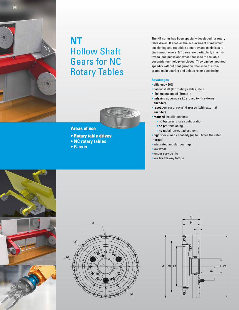
NT Hollow Shaft Gears for NC Rotary Tables
The NT series has been specially developed for rotary table drives. It enables the achievement of maximum positioning and repetition accuracy and minimises ra- dial run-out errors. NT gears are particularly insensi-tive to load peaks and wear, thanks to the reliable eccentric technology employed. They can be mounted speedily without confi guration, thanks to the inte-grated main bearing and unique roller cam design.
Advantages• efficiency 80%• hollow shaft (for routing cables, etc.)• high output speed (70 min-1)• indexing accuracy ±2.5 arcsec (with external
encoder)• repetition accuracy ±1.0 arcsec (with external
encoder)• reduced installation time:
no hysteresis loss configuration no pre-tensioning no radial run-out adjustment
• high shock-load capability (up to 5 times the rated torque)
• integrated angular bearings• low wear• longer service life• low breakaway torque
Areas of use
• Rotary table drives
hollow shaft (for routing cables, etc.)• high output speed (70 min• indexing accuracy ±2.5 arcsec (with external
encoder)• repetition accuracy ±1.0 arcsec (with external
encoder)• reduced installation time:
no hysteresis loss configurationno pre-tensioningno radial run-out adjustment
• high shock-load capability (up to 5 times the rated torque)
NAB_2012_Uebersichtsbr_230x315_RZ.indd 29 10.05.12 15:18

Model Standard ratio
Rated torque (Nm)
Allowable torque Max. speedHysteresis
loss (arcmin)
Bearing support capacity
Acceleration / deceleration (Nm)
Intermittent drive (min-1)
Tilting rigidity (Nm/arcmin)
Allowable tilting torque (Nm)
Axial load (Nm)
550 60 1.471 2.942 70 < 1,0 19.613 5.394 32.362
650 60 2.059 4.119 70 < 1,0 34.323 9.807 32.362
Model A( mm)
B( mm)
C H7( mm)
D h7 ( mm)
E h7( mm)
F (mm)
G(mm)
H(mm)
I(mm)
J(mm)
K(mm)
L(mm)
M(mm)
N(mm)
Weight (kg)
550 549 446 348 550 135 123 144 140 30 20 8 ø13 520 12 M12 382 160
650 669 556 420 670 160 141 146 142 32 24 12 ø13 640 12 M16 475 220
Specifications
Dimensions
NT | Special gears for machine tools |27
NAB_2012_Uebersichtsbr_230x315_RZ.indd 30 10.05.12 15:18

Precision and Power for Innovative Applications
Exact alignment: solar technologySolar panels need to continually adjust their position relative to that of the sun. This is essential if solar power stations are to work efficiently. Nabtesco gears are ideal for this application. They are highly accurate, even where the smallest movement increments are involved, robust and requiring minimum maintenance.
Accurate diagnosis: medical technologyThe technology utilised in imaging methods and radiotherapy must move with precision around patients. Nabtesco precision gears ensure that precise positioning is achieved to ensure that this functions optimally. The result is conclusive images and targeted treatment.
Precision movement: roboticsInstallation space for industrial robots is very limited – making this the perfect location for the use of extremely compact, high-precision Nabtesco gears. Hollow shafts for the routing of cables and hoses and various output support options ensure simple integration in the layouts.
High resilience: industrial engineeringExtreme forces, complex procedures, thousands of repetitions: industry makes maximum demands on technology when it comes to precision and resilience. Nabtesco meets these demands effortlessly, provid- ing a broad selection of component sets and gear-heads. Eccentric gears have a long service life, are insensitive to shock loading and enable optimum positioning and, equally, reliable tool changing.
28| Applications
NAB_2012_Uebersichtsbr_230x315_RZ.indd 31 10.05.12 15:18

28| Applications Applications |29
NAB_2012_Uebersichtsbr_230x315_RZ.indd 32 10.05.12 15:18

2.
2.
1.
1.
4. 3.
Input Shaft and Pinion
Standard
• Standard pinion available in two different dimensions
• Processing can be realised by the customer
Standard
1. Centre gear driven by pinion
Customised
2. Supported centre gear for pulley drive
Customised
1. For motor shaft with key way
2. For conical motor shaft with key way
3. Power lock connection for straight motor shaft
4. Supported input shaft for pulley drive
Additional designs available on request
30| Input shaft and pinion
RV-C series
RV and RV-E series
NAB_2012_Uebersichtsbr_230x315_RZ.indd 33 10.05.12 15:18

02|
RV-C Hollow shaftT up to 11.760 Nmi up to 283
NAB_2012_Uebersichtsbr_230x315_RZ_11-2012.indd 4-5 12.11.12 11:58

Nabtesco Motion Control23976 Freeway Park DriveFarmington Hills Michigan 48335
Phone: 248-553-3020nabtescomotioncontrol.com