Maximization of Oil Output of a Treadle-Powered Peanut Oil ...
35
Maximization of Oil Output of a Treadle-Powered Peanut Oil Press by Ravi M. Patel SUBMITTED TO THE DEPARTMENT OF MECHANICAL ENGINEERING IN PARTIAL FULFILLMENT OF THE REQUIREMENTS FOR THE DEGREE OF BACHELOR OF SCIENCE AT THE MASSACHUSETTS INSTITUTE OF TECHNOLOGY JUNE 2007 @2007 Ravi M. Patel. All rights reserved. The author hereby grants to MIT permission to reproduce and to distribute publicly paper and electronic copies of this thesis document in whole or in part in any medium now known or hereafter created. Signature of Author: Certified by:/ Accepted by: -ASSACHUSETTS INSTITUTE. F TECHNOLOGY JUN 2 1 2007 ARCHIES LIBRARIES SV Department of Mechanical Engineering 7 / May 11, 2007 Amy Smith enior Ixrgk - the Department of Mechanical Engineering Thesis Supervisor John H. Lienhard V Professor of Mechanical Engineering Chairman, Undergraduate Thesis Committee 1
Transcript of Maximization of Oil Output of a Treadle-Powered Peanut Oil ...

Maximization of Oil Output of a Treadle-Powered Peanut Oil Press
by
Ravi M. Patel
SUBMITTED TO THE DEPARTMENT OF MECHANICAL ENGINEERING INPARTIAL FULFILLMENT OF THE REQUIREMENTS FOR THE DEGREE OF
BACHELOR OF SCIENCEAT THE
MASSACHUSETTS INSTITUTE OF TECHNOLOGY
JUNE 2007
@2007 Ravi M. Patel. All rights reserved.
The author hereby grants to MIT permission to reproduceand to distribute publicly paper and electronic
copies of this thesis document in whole or in partin any medium now known or hereafter created.
Signature of Author:
Certified by:/
Accepted by:
-ASSACHUSETTS INSTITUTE.F TECHNOLOGY
JUN 2 1 2007 ARCHIES
LIBRARIES
SV
Department of Mechanical Engineering7 / May 11, 2007
Amy Smithenior Ixrgk - the Department of Mechanical Engineering
Thesis Supervisor
John H. Lienhard VProfessor of Mechanical Engineering
Chairman, Undergraduate Thesis Committee
1
Maximization of Oil Output of a Treadle-Powered Peanut Oil Press
by
Ravi M. Patel
Submitted to the Department of Mechanical Engineeringon May 11, 2007 in partial fulfillment of the
requirements for the Degree of Bachelor of Science in Engineeringas recommended by the Department of Mechanical Engineering
ABSTRACT
The manual processing of food products has become a substantial part of the dailyroutine of a typical household in the developing world. Consumption of oil is anessential part of an individual's diet and thus, the production of oil is an essentialactivity. In many communities, this oil is obtained by manually pressing it frompeanuts. In order to more efficiently and easily express oil from peanuts, a designfor a treadle-powered peanut oil press was created.
My thesis work will attempt to further increase the amount of oil extracted byoptimizing the design of this peanut oil press. The press transfers the motion of thetreadle to the horizontal motion of a piston that presses the peanuts via a rotatingcam. The focus of this thesis will be optimizing the design of the cam with respectto oil yield. The shape of the cam determines the displacement profile of thepiston's compression of the peanuts. I will determine the optimal profile bydesigning and performing experiments on a variety of different displacementprofiles and measuring the amount of oil extracted from the pressed peanuts. Theresults of these experiments will then determine the optimal cam design.
Thesis Supervisor: Amy SmithTitle: Senior Lecturer in the Department of Mechanical Engineering
Acknowledgements
First and foremost, I'd like to thank my advisor, Amy Smith, for supporting me and
offering advice throughout the process of conducting this research. I am especially grateful
for having the unique opportunity of participating in Amy's MIT D-Lab program, which has
introduced me to the exciting field of appropriate technology and has inspired me to continue
to study topics in international development. It has been a privilege to be a student and
advisee of Amy Smith throughout my career at MIT.
I would also like to thank Pierce Hayward, who provided invaluable insight, advice, and
suggestions regarding the technical aspects of my thesis. His kind and gracious help in
providing me with the equipment necessary for successful experiments and in offering his
unique expertise greatly helped me better appreciate the research I was doing.
Contents
1 Introduction
2 Background
2.1 History of Oil Press Technologies for the Developing World ..........
2.2 Current Peanut Oil Press Design . . . . . . . . . . . . . . . . . . . . ....
2.3 Cam Design ..................................
2.4 Peanut Mechanics ................ ................
3 Experimental Procedure
3.1 Experimental Apparatus ........... . ............
3.2 Experiment Design ................................
4 Results
5 Discussion
5.1 Peanut Pressing Behavior
5.1.1 Displacement Profile
5.1.2 Force Profile .....
5.2 Proposed Cam Designs . ..
6 Conclusions and Future Research
References
A Full experimental results of peanut pressing
. . . . . . . . . . . . . . . . . . . . . . . . .
........................... °
. . . . . . . . . . . . . . . . . . . . . . . . . .° .
. . . . . . . . . .° . . . . . . . . . .° . . . . . . .
List of Figures
1 Women in Mwape, Africa pressing peanuts for oil [12] . ............ 7
2 Trial of the Bielenberg Press in Mwape [12] . .................. 9
3 CAD model of treadle-powered peanut oil press [6] . ............. 11
4 Proof of concept prototype (non-functional) of treadle-powered oil press [6] . 11
5 Template for cam design ................. .......... . 14
6 Model of a screw press used in past research [5] . ........ .... . . . 15
7 Relationship between pressure and oil yield on pressing groundnuts [3] . . .. 16
8 Applied pressure and oil output as a function of time for pressing rapeseeds
in a piston-cylinder rig [7] .......... .. .. .. ......... . 17
9 Instron machine used for testing ........... ........ ...... 19
10 Piston pressing peanuts in the cylindrical chamber . .............. 19
11 Chambers used to hold peanuts during compression . ............. 20
12 Force-displacement curve for smaller container . ............. . . . 23
13 Force-displacement curve for larger container . ................. 24
14 Speed of pressing vs. oil yield for the small container (top) and large container
(bottom) ..................................... 25
15 Remaining peanut mass after pressing ................... ... 26
16 Stages in compression ................... ............ 26
17 Proposed cam design ........... . . .. .......... 29
List of Tables
1 Profiles tested for small container ........... .... . . . ..... 21
2 Profiles tested for large container ...... .......... . . . .. 21
3 Results for Small Container .......................... . . . . . 22
4 Results for Large Container . . . . ................. . . . . . 22
5 Full data set for experiments with small container . .............. 34
6 Full data set for experiments with large container . .............. 35
1 Introduction
Communities in developing countries rely mainly on subsistence farming to feed and pro-
vide for their members due to the lack of a local market supplying food products. As a
result, people in these societies spend an inordinate amount of time farming, preparing, and
cooking food. The processing of food products is a necessary activity in many regions of
developing countries, particularly sub-Saharan countries in Africa.
The motivation for this project came through a series of trips to developing regions in
Africa when MIT D-Lab teams recognized a need for improved oil expression techniques.
Oils are often an essential part of individual diets, and the processed oil available in the
open market is often imported from other countries and can be prohibitively expensive.
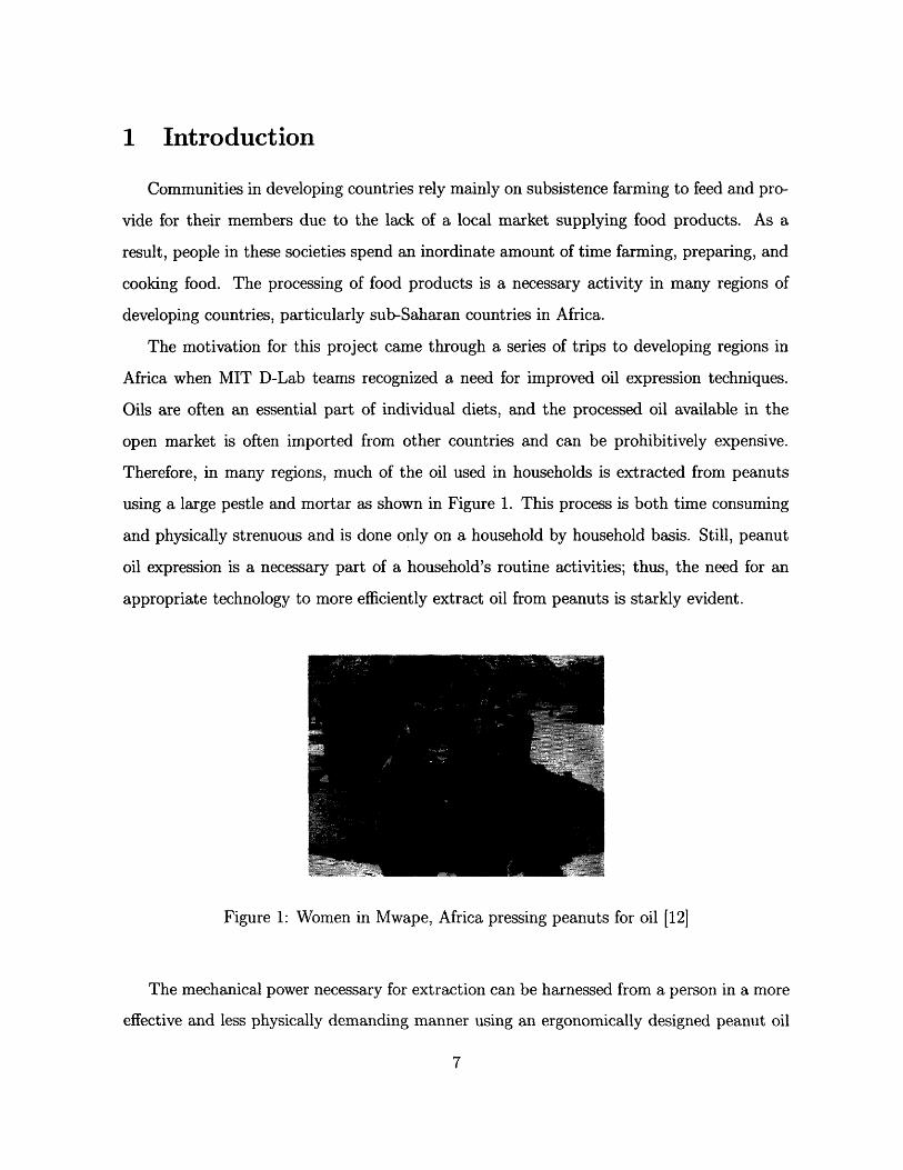
Therefore, in many regions, much of the oil used in households is extracted from peanuts
using a large pestle and mortar as shown in Figure 1. This process is both time consuming
and physically strenuous and is done only on a household by household basis. Still, peanut
oil expression is a necessary part of a household's routine activities; thus, the need for an
appropriate technology to more efficiently extract oil from peanuts is starkly evident.
Figure 1: Women in Mwape, Africa pressing peanuts for oil [12]
The mechanical power necessary for extraction can be harnessed from a person in a more
effective and less physically demanding manner using an ergonomically designed peanut oil
press. While some oil press designs have enjoyed success in the developing world, other meth-
ods of harnessing human power input more effectively have only recently been explored. One
of these methods is being developed by D-Lab and uses treadle power to move a piston into
a chamber of peanuts. Over longer periods of time, treadle power places less strain on a
user's body than a device utilizing the upper body. In addition, a treadle-powered device
has proven to be manufacturable in developing countries, as evidenced by projects such as
treadle-powered water pumps.
The focus of this thesis is to optimize the efficiency of the oil press powered by a human
treadle motion by focusing on the motion of the piston. Successful completion of this re-
search will attempt to lead to the design of a final machine that will extract the maximum
amount of oil from a given amount of peanuts. A variety of tests were conducted to obtain
the displacement profile of the piston's motion that optimizes oil output. These tests in-
volved pressing peanuts at varying speeds and determining the oil yield as well as the force
required for pressing.
2 Background
Broadly speaking, this thesis is focused on the mechanical properties of peanuts and the
application of these properties to optimize oil expression in the particular treadle-powered
design. To form the basis of this research, modern oil press technologies for the develop-
ing world will be evaulated, and the theory behind oil expression from groundnuts will be
presented.
2.1 History of Oil Press Technologies for the Developing World
The project of creating a more efficient mechanical method of extraction of oil from
peanuts has been going on for over two decades. The first device to make a significant
impact in communities in the developing world was developed by engineer Carl Bielenberg
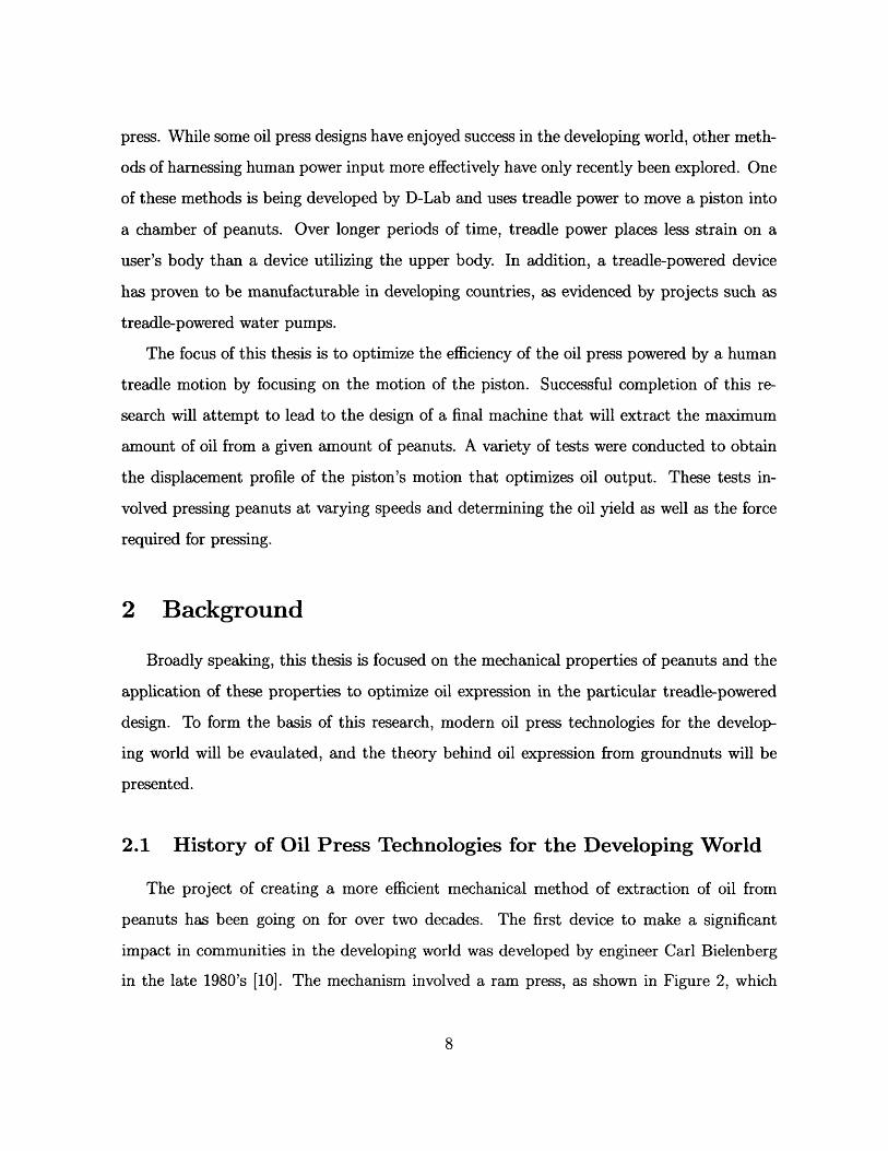
in the late 1980's [10]. The mechanism involved a ram press, as shown in Figure 2, which
required the user to pull down a lever that pushes a piston, crushing the peanuts. The design
of the press represented an improvement upon previous expression methods because it was
exclusively human powered and could be run continuously. In contrast, other methods often
expressed oil from peanuts in batches. In addition, the length of time at which the user is
physically strained is reduced using the Bielenberg press.
Figure 2: Trial of the Bielenberg Press in Mwape [12]
The Bielenberg press demonstrated the usefulness of a productive peanut oil press. Nutri-
tional benefits were observed through surveys demonstrating higher oil outputs and resulting
increased consumption of oil. Economic benefits resulted from the creation of a market for
oil; because the press allowed for the production of surpluses, some users began to sell oil in
the marketplace [4].
The Bielenberg press was particularly innovative not only because of its economic and
household benefits, but also because it was an appropriate technology. One of the goals for
technology in the developing world is to ensure that it can be manufactured locally and that
it is relatively inexpensive. The Bielenberg press achieved these critical aspects in addition
to its mechanical advantages to the user.
The concept of the Bielenberg press then motivated the design of a new, more ergonomic
mechanism to press peanuts. The ram press required considerable upper body strength to
operate and it was difficult to control the speed of pressing since the motion of the pressing is
directly determined by the operator. Once the expression of oil began, the speed of pressing
should be slowed significantly. However, it is neither ergonomic nor intuitive for a human
operator to press the ram at a sufficiently slow rate. Thus a "dwell" time was introduced
where the peanuts were not compressed at all since this is the closest to 'very slow' that is
ergonomically achievable. Ideally, the peanuts would be continuously compressed even at
slow rates.
To remedy this issue and in order to decrease physical strain on the operator, other
methods of human mechanical input were explored and a treadle powered mechanism was
pursued. Other possible types of peanut oil extraction techniques include chemical methods,
a screw press, or a hydraulic press. Unfortunately, in a developing country context, these
designs run into problems of cost, availability of resources, and manufacturability. Thus, the
need for a more user-friendly peanut oil press is apparent.
2.2 Current Peanut Oil Press Design
The design that is the subject of this thesis is a treadle-powered peanut oil press origi-
nally developed in the spring of 2006. The original concept of the device, as shown in Figure
3, converts the treadle motion of the user to a horizontal motion that presses the peanuts.
The design for actuating the piston device which pressed the peanuts was still maintained
but instead of a large lever to move the piston, the motion of the treadles was utilized. Still,
in order to incorporate the treadles, a new design for the entire machine had to be created
to accomodate the concept. Since the time when the CAD model in Figure 3 was designed,
there have been changes to the design which is the subject of research that was done con-
currently with this thesis research. The modified design concept is detailed in Daipan Lee's
thesis entitled "Peanut Oil Press Redesign for Developing Countries" submitted in May 2007.
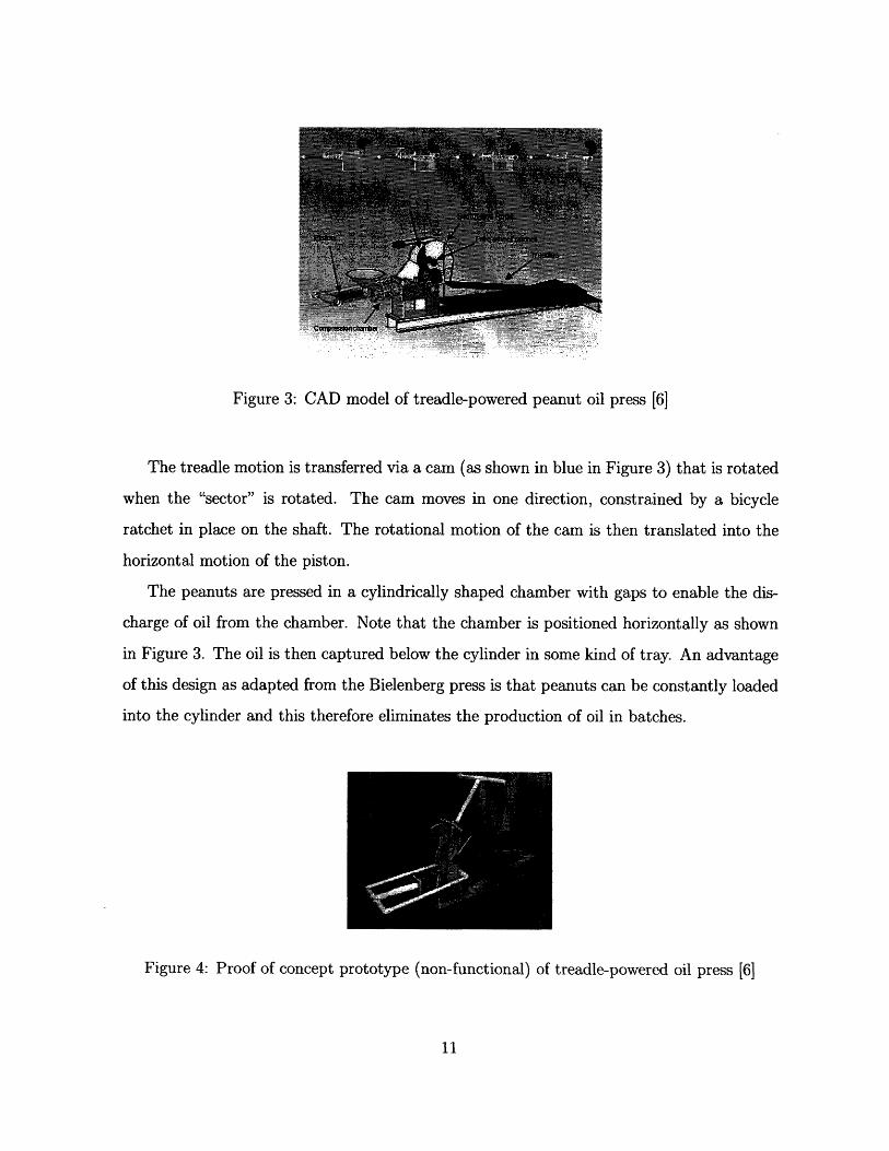
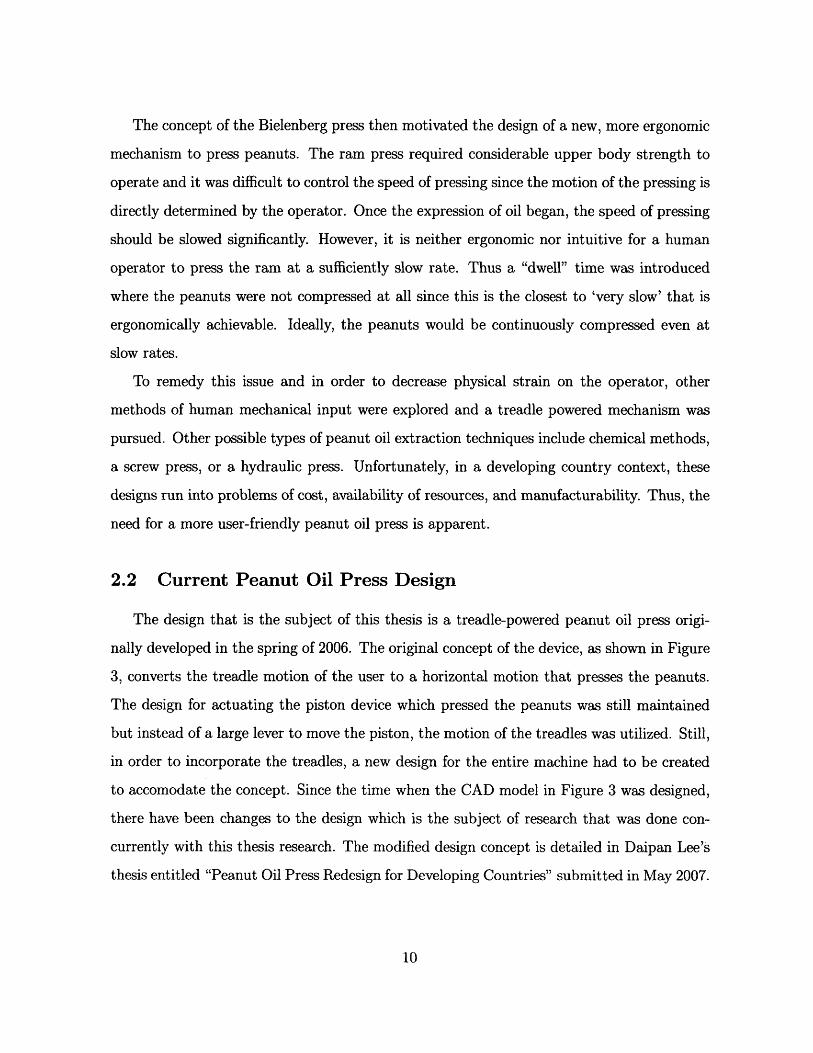
Figure 3: CAD model of treadle-powered peanut oil press [6]
The treadle motion is transferred via a cam (as shown in blue in Figure 3) that is rotated
when the "sector" is rotated. The cam moves in one direction, constrained by a bicycle
ratchet in place on the shaft. The rotational motion of the cam is then translated into the
horizontal motion of the piston.
The peanuts are pressed in a cylindrically shaped chamber with gaps to enable the dis-
charge of oil from the chamber. Note that the chamber is positioned horizontally as shown
in Figure 3. The oil is then captured below the cylinder in some kind of tray. An advantage
of this design as adapted from the Bielenberg press is that peanuts can be constantly loaded
into the cylinder and this therefore eliminates the production of oil in batches.
Figure 4: Proof of concept prototype (non-functional) of treadle-powered oil press [6]
Several prototypes have been built in the past year through MIT D-Lab; one such proof
of concept prototype is shown in Figure 4. This prototype was the first to be built and was
not functional but demonstrated the design concept. Areas of research that are critical to
optimization of the oil press include the force applied on the peanuts, the amount of human
force input required, operating time, efficiency, and other concerns regarding manufactura-
bility and sustainability. This thesis aims to focus on the optimization of the peanut oil press
with respect to the motion of the piston. As stated earlier, this motion is directly related to
the design of the cam. Therefore the cam design is a critical component of a product that
yields the greatest possible oil output.
2.3 Cam Design
A cam is often used to convert rotary motion into linear motion. In addition, it allows
for a more controlled and continous motion that would incorporate the "dwell" time into the
pressing cycle. The cam controls this motion and is a critical feature of the press design.
The design of the prototype converts the treadle motion to a rotary motion and then
through a cam converts it to a horizontal linear motion. The shape of the cam directly
guides the movement of the piston in and out of the cylindrical chamber. Earlier prototypes
of the oil press employed arbitrary shapes for the cam. The cam however can be optimized
to move the piston against the peanuts at the optimal speeds.
This particular cam should be designed with four important factors in mind: the length
of the chamber, the desired linear speed of the piston, the length of one period (or one
revolution), and the proportion of the chamber that the piston should press through. The
length of the chamber is a design choice made by the designer of the final product. The
length of a period of revolution is also a design choice but is primarily a function of user
preferences in terms of ergonomics and throughput.
This research is concerned with the other two variables: the desired linear speed of the
piston and the proportion of the chamber that the piston should press through. In order
to mathematically and geometrically present the problem of designing a cam, I propose the
following simple mathematical model.
The model will be defined by the desired speeds that the piston moves through a series
of N time stages, indexed by the variable k:
L = Total length of cylindrical chamber
Pk - Proportion of chamber that piston moves into the chamber in the kth stage
a~k Desired linear velocity (not speed) of piston through the kth stage
T - Desired time per period of revolution
Note that E k=1 Pk is strictly less than 1 since the piston is not moving through the entire
length of the chamber and also some of the Pk values will be negative to signify moving out
of the chamber . Therefore, the piston does not move a distance of L but moves a total
distance of ENk1 IpkI. To see this, note that the sum of the positive pk values should be
precisely equivalent to the magnitude of the sum of the negative Pk values since the piston
moves in and out of the chamber the same distance. So, 2dl is the proportion of L that
the piston moves into the chamber.
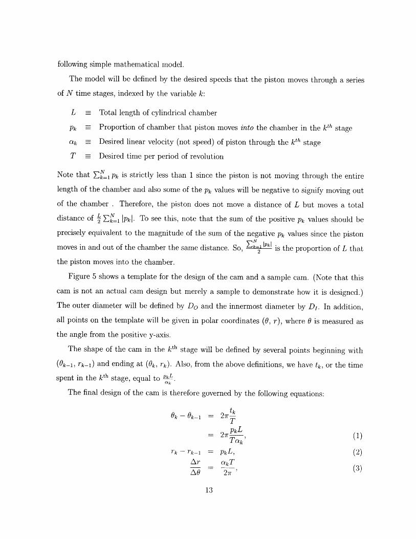
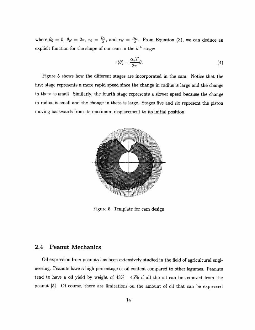
Figure 5 shows a template for the design of the cam and a sample cam. (Note that this
cam is not an actual cam design but merely a sample to demonstrate how it is designed.)
The outer diameter will be defined by Do and the innermost diameter by DI. In addition,
all points on the template will be given in polar coordinates (0, r), where 0 is measured as
the angle from the positive y-axis.
The shape of the cam in the kth stage will be defined by several points beginning with
(0k-1, Tk-1) and ending at (Ok, rk). Also, from the above definitions, we have tk, or the time
spent in the kth stage, equal to pkL
The final design of the cam is therefore governed by the following equations:
O, - Ok-1 = 27rtk
TpkL= 2 r--, (1)Tak'
Tk - rk-1 pkL, (2)Ar
2 &kTAO 2 (3)
where 00 = 0, ON = 27r, ro = , and rN = D. From Equation (3), we can deduce an
explicit function for the shape of our cam in the kth stage:
rr() = .kT027r (4)
Figure 5 shows how the different stages are incorporated in the cam. Notice that the
first stage represents a more rapid speed since the change in radius is large and the change
in theta is small. Similarly, the fourth stage represents a slower speed because the change
in radius is small and the change in theta is large. Stages five and six represent the piston
moving backwards from its maximum displacement to its initial position.
Figure 5: Template for cam design
2.4 Peanut Mechanics
Oil expression from peanuts has been extensively studied in the field of agricultural engi-
neering. Peanuts have a high percentage of oil content compared to other legumes. Peanuts
tend to have a oil yield by weight of 43% - 45% if all the oil can be removed from the
peanut [5]. Of course, there are limitations on the amount of oil that can be expressed

due to processing restrictions. Previous research has focused both on industrial methods of
oil expression as well as on simpler technologies. Pressing has proved to be advantageous
because it is less capital intensive, technically less extensive, less labor intensive, and is a
continuous process [9]. Most of the research with pressing has used a screw press as pictured
in Figure 6; since the purposes of this thesis research is to analyze peanuts under pressure,
we can still relate the current literature with my results.
Feed hopper
a
Figure 6: Model of a screw press used in past research [5]
With respect to obtaining oil by applying pressure, research has found that the most
critical factors in the amount of oil output are heating temperature, applied pressure, press-
ing time, and moisture content of peanuts [5]. In my experiments, all the peanuts used were
from the same batch and thus on average the moisture content of peanuts used in different
trials was roughly the same.
Pressing time and applied pressure are both functions of the speed at which the peanuts
are pressed. The literature generally concludes that increased pressing time and applied
pressure will contribute to higher oil yields. Hamzat and Clarke determined that increasing
pressing time to about one minute significantly increases oil yield but after that point, there
is only a slight increase in output [3]. Increasing the magnitude of the applied pressure also

increases the quantity of oil yield. As shown in figure 7, there is a higher rate of yield increase
(signified by the slope) at lower pressures and a slower - and even negative - growth rate at
higher pressures.
P=s1e. MPA
Figure 7: Relationship between pressure and oil yield on pressing groundnuts [3]
The last critical element is therefore the temperature. Various authors have attempted
to determine the optimal temperature of the peanuts used in oil expression via pressure.
Adeeko and Ajibola found an optimal temperature between 90 0 C and 115'C and concluded
that excessive heating will cause both significant moisture loss and also cause the proteins
in the nuts to coagulate, thus reducing the viscosity of the expressed oil [1]. Oyionlola,
Ojo, and Adekoya concluded that the optimal temperature is generally above 70'C [9] while
Goodrum reported an optimal temperature of 95.6'C [2].
Other elements of peanut expression via pressure do play a factor in oil yield though
they are less significant. This includes heating time and coarseness of the nuts. Optimal
heating time was found to be approximately half an hour [1]. In addition, past research
demonstrated that coarsely ground nuts provide higher oil yields than both finely ground
nuts and non-ground nuts [3]. Thus, in the field, the peanuts should be coarsely ground to
demonstrate maximum oil yield.
The physical features of the peanut during oil expression have also been investigated.
Peanuts in their original state store oil within the cells that comprise the peanut. The oil
expression process proceeds in four distinct stages: oil flows through pores in the individual
cell walls; the oil flows through the inter-cell voids; the oil flows from the peanut and fills
the 'inter-peanut' voids; and finally the oil is pressed out of the bulk of peanuts [8]. The
point at which oil appears on the surface of the peanut is called the oil-point. The oil-point
pressure is the pressure required to get to the oil-point. This pressure, Po has been shown to
be a function of the rate of deformation of the bed of nuts, R, and the moisture content of
the nuts, m; a general equation that governs the oil-point pressure, in MPa, of oilseeds is
Po = K1 exp[K 2ma + K3 R)],
where K 1, K2 , K3 , and a are constants particular to the type of oilseed [13].
A440
(5)
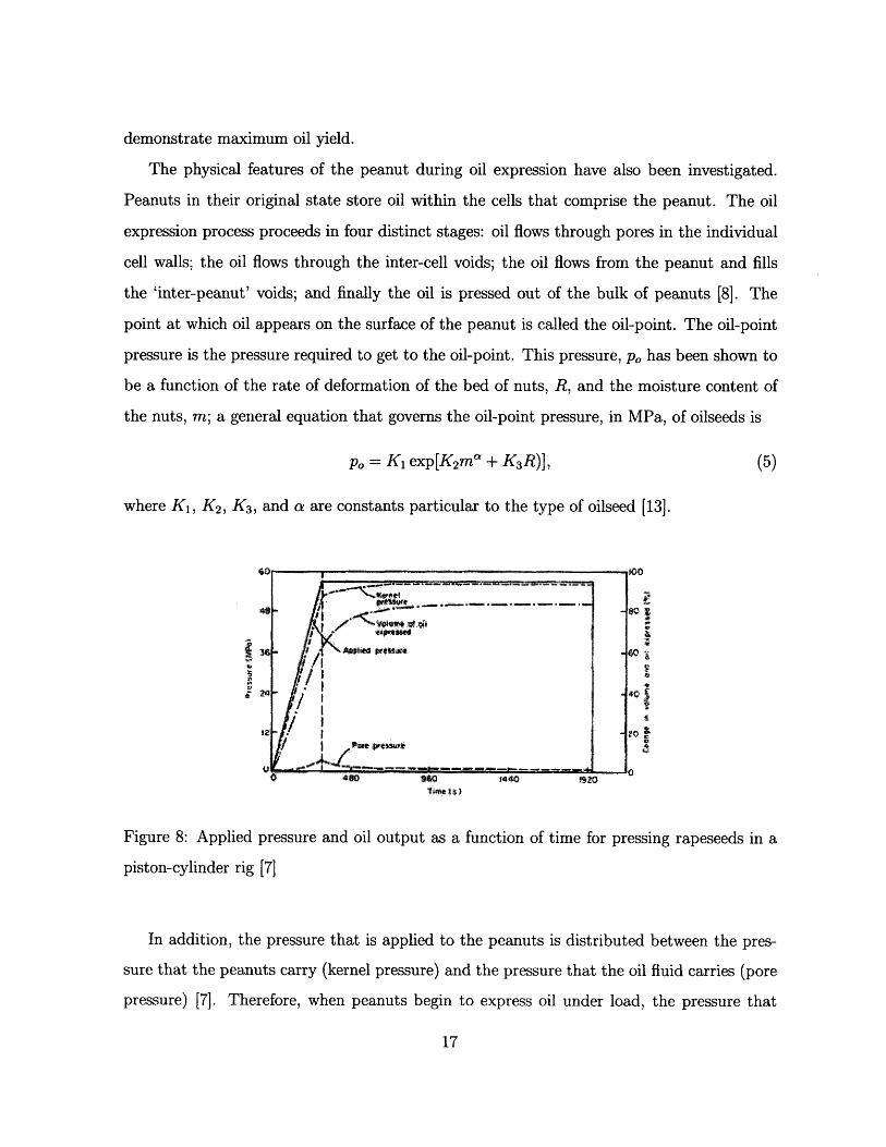
Figure 8: Applied
piston-cylinder rig
pressure and oil output as a function of time for pressing rapeseeds in a
[7]
In addition, the pressure that is applied to the peanuts is distributed between the pres-
sure that the peanuts carry (kernel pressure) and the pressure that the oil fluid carries (pore
pressure) [7]. Therefore, when peanuts begin to express oil under load, the pressure that
4.8-
* 1 z*Se
Pip IiI it/I
/ ; Put .. ... sw1 ( '/I",
.. . . .. .. .. . . .. . . . rl • .
f+I3Lr
cj
Pe
5
LcXu
is used to express more oil from the peanuts reduces. The sharing of the load is relevant
because the more oil that remains in the peanut bulk, the less the amount of oil that can
be further expressed. Figure 8 shows a rough approximation to the split between the kernel
pressure and pore pressure in a rapeseed pressing experiment. Note that as time goes on,
more and more of the pressure is being used to express oil from the seeds rather than to
push oil from the chamber.
For the particular experiments that this thesis requires, the main concern is the effect of
piston speed on the oil yield. Applying the results in the literature, I hypothesize that at
slow speeds, there is higher oil yield. This is due to the fact that at slow speeds, the oil is
allowed more time to leave the chamber and thus allow a greater portion of the pressure to be
the 'kernel pressure' that actually contributes to oil expression. On the other hand, at faster
speeds, the oil is kept in the chamber for a larger proportion of the time of compression.
As a result, the amount of work done on compressing the peanuts for oil is less due to the
oil bearing a higher 'pore pressure.' In sum, slower speeds will cause the total pressure to
be distributed more heavily onto the actual peanuts than the oil in the inter-peanut voids.
Therefore, our results should correspond to the literature as well as to a trend that lower
speeds correlate to higher oil yields.
3 Experimental Procedure
The intention of my experiments therefore is to determine the displacement vs. time
profile for the movement of the piston that maximizes the expression of oil from the peanuts
by applying pressure. An optimal cam design can then be derived from the optimal profile.
3.1 Experimental Apparatus
The experiment utilized the Instron machine in MIT's Mechanics and Materials Lab. This
setup also included a cylinder with slits to hold the piston, a piston to press the peanuts in
the cylinder, a tray to collect the oil, and a computer attached to the Instron machine to
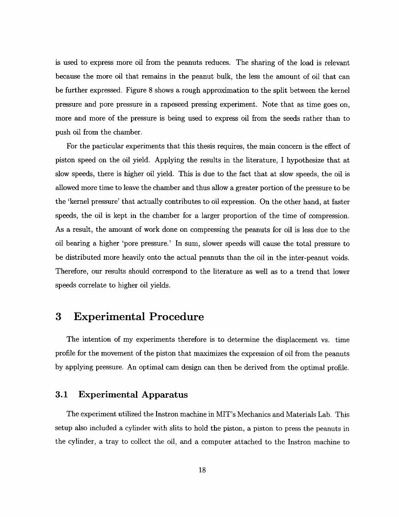
capture force, displacement, and time data. The Instron machine is shown in Figure 9.
Figure 9: Instron machine used for testing
A piston is attached to the upper bar, which is moved vertically by the Instron ma-
chine. The peanut-filled chamber and the tray to collect the oil are placed beneath the
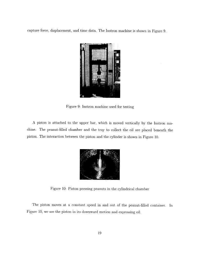
piston. The interaction between the piston and the cylinder is shown in Figure 10.
Figure 10: Piston pressing peanuts in the cylindrical chamber
The piston moves at a constant speed in and out of the peanut-filled container. In
Figure 10, we see the piston in its downward motion and expressing oil.
3.2 Experiment Design
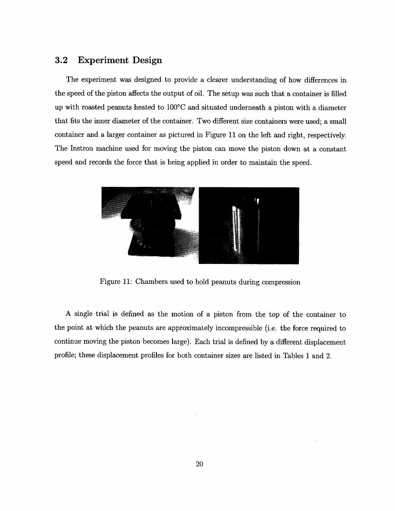
The experiment was designed to provide a clearer understanding of how differences in
the speed of the piston affects the output of oil. The setup was such that a container is filled
up with roasted peanuts heated to 1000C and situated underneath a piston with a diameter
that fits the inner diameter of the container. Two different size containers were used; a small
container and a larger container as pictured in Figure 11 on the left and right, respectively.
The Instron machine used for moving the piston can move the piston down at a constant
speed and records the force that is being applied in order to maintain the speed.
Figure 11: Chambers used to hold peanuts during compression
A single trial is defined as the motion of a piston from the top of the container to
the point at which the peanuts are approximately incompressible (i.e. the force required to
continue moving the piston becomes large). Each trial is defined by a different displacement
profile; these displacement profiles for both container sizes are listed in Tables 1 and 2.
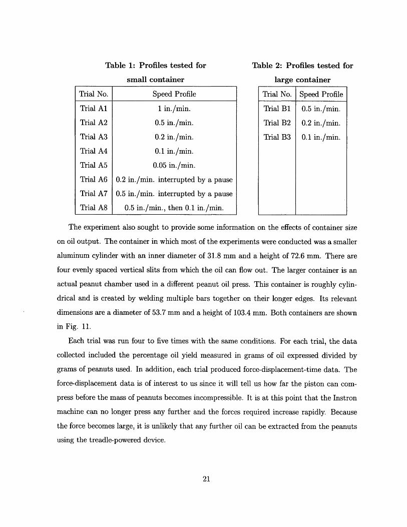
Table 1: Profiles tested for Table 2: Profiles tested for
small container large container
The experiment also sought to provide some information on the effects of container size
on oil output. The container in which most of the experiments were conducted was a smaller
aluminum cylinder with an inner diameter of 31.8 mm and a height of 72.6 mm. There are
four evenly spaced vertical slits from which the oil can flow out. The larger container is an
actual peanut chamber used in a different peanut oil press. This container is roughly cylin-
drical and is created by welding multiple bars together on their longer edges. Its relevant
dimensions are a diameter of 53.7 mm and a height of 103.4 mm. Both containers are shown
in Fig. 11.
Each trial was run four to five times with the same conditions. For each trial, the data
collected included the percentage oil yield measured in grams of oil expressed divided by
grams of peanuts used. In addition, each trial produced force-displacement-time data. The
force-displacement data is of interest to us since it will tell us how far the piston can com-
press before the mass of peanuts becomes incompressible. It is at this point that the Instron
machine can no longer press any further and the forces required increase rapidly. Because
the force becomes large, it is unlikely that any further oil can be extracted from the peanuts
using the treadle-powered device.
Trial No. Speed Profile
Trial Al 1 in./min.
Trial A2 0.5 in./min.
Trial A3 0.2 in./min.
Trial A4 0.1 in./min.
Trial A5 0.05 in./min.
Trial A6 0.2 in./min. interrupted by a pause
Trial A7 0.5 in./min. interrupted by a pause
Trial A8 0.5 in./min., then 0.1 in./min.
Trial No. Speed Profile
Trial B1 0.5 in./min.
Trial B2 0.2 in./min.
Trial B3 0.1 in./min.
4 Results
The results for oil yield for different displacement profiles are shown in Tables 3 and 4.
The raw data for each run of each trial is shown in Appendix A. % Yield is given in weight.
Table 3: Results for Small Container
Trial No. Speed Profile % Yield Standard Deviation
Trial Al 1 in./min. 12.68% 2.82%
Trial A2 0.5 in./min. 16.79% 3.43%
Trial A3 0.2 in./min. 17.34% 4.80%
Trial A4 0.1 in./min. 27.65% 2.65%
Trial A5 0.05 in./min. 26.42% 3.83%
Trial A6 0.2 in./min. interrupted by a pause 16.47% 5.33%
Trial A7 0.5 in./min. interrupted by a pause 15.03% 3.21%
Trial A8 0.5 in./min., then 0.1 in./min. 24.77% 5.38%
Table 4: Results for Large Container
Trial No. Speed Profile % Yield Standard Deviation
Trial B1 0.5 in./min. 16.01% 2.26%
Trial B2 0.2 in./min. 16.19% 5.05%
Trial B3 0.1 in./min. 20.17% 2.56%
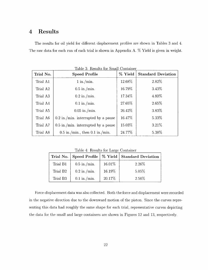
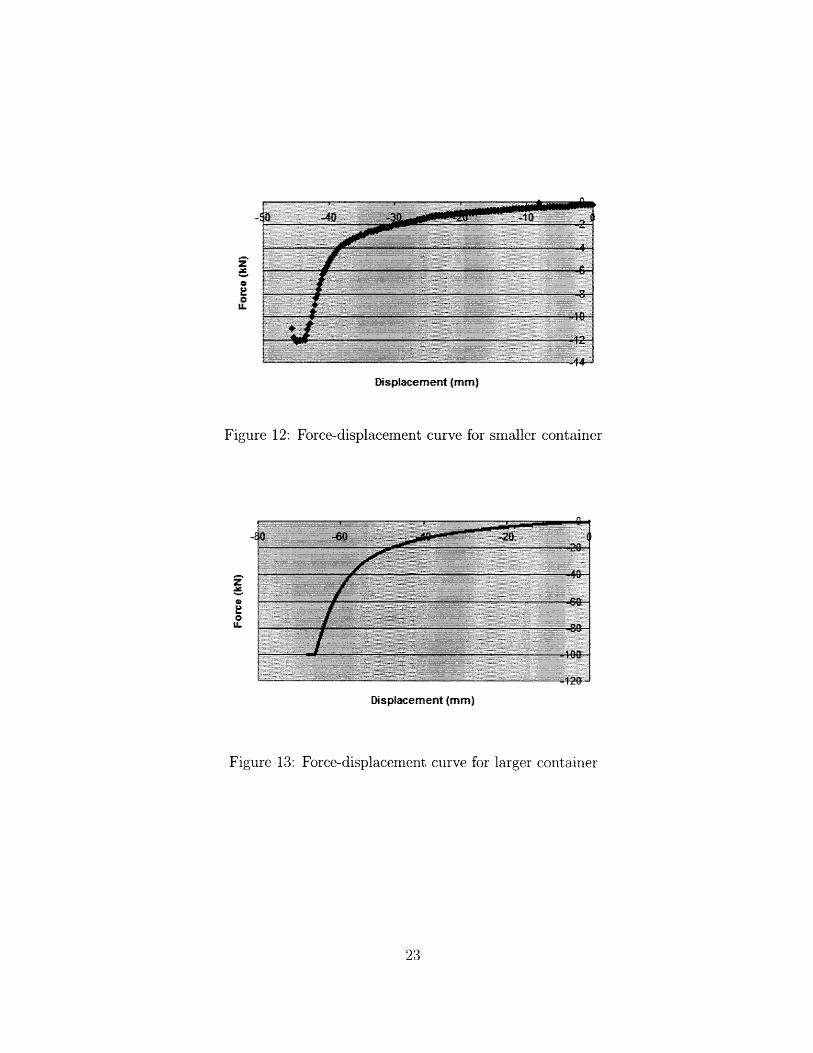
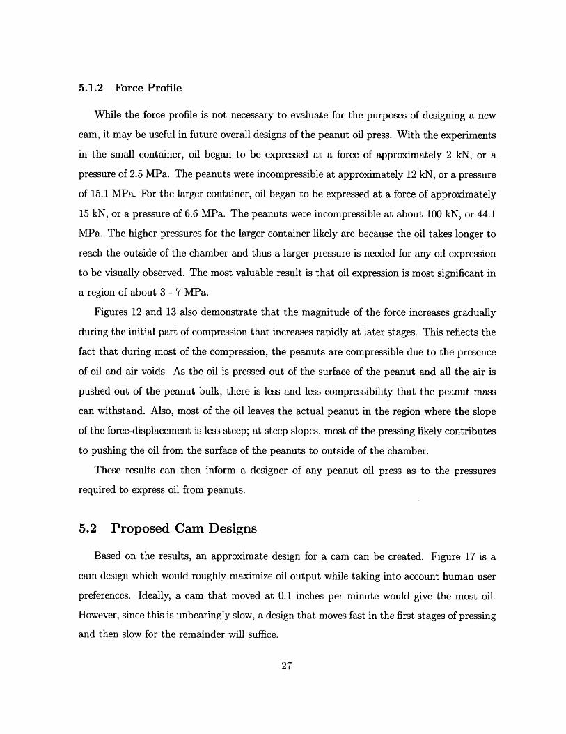
Force-displacement data was also collected. Both the force and displacement were recorded
in the negative direction due to the downward motion of the piston. Since the curves repre-
senting this data had roughly the same shape for each trial, representative curves depicting
the data for the small and large containers are shown in Figures 12 and 13, respectively.
Z
l.
u.
Displacement (mm)
Figure 12: Force-displacement curve for smaller container
AZi
SIL
Displacement (mm)
Figure 13: Force-displacement curve for larger container
5 Discussion
5.1 Peanut Pressing Behavior
5.1.1 Displacement Profile
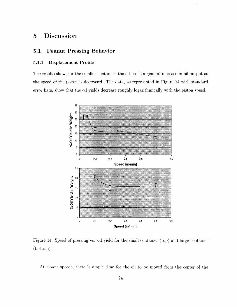
The results show, for the smaller container, that there is a general increase in oil output as
the speed of the piston is decreased. The data, as represented in Figure 14 with standard
error bars, show that the oil yields decrease roughly logarithmically with the piston speed.
06
Speed {inimin)
0 , 1i
Z0O>-
o
0 e 1 302 03
Speed (infmin)
Figure 14: Speed of pressing
(bottom)
vs. oil yield for the small container (top) and large container
At slower speeds, there is ample time for the oil to be moved from the center of the
container to the outer edge. However, at faster speeds, there is less time. This will cause
two things: first, more oil will remain in the chamber and thus there is a lesser oil output;
secondly, the more oil that remains in the chamber, the less pressure is used to express oil
from the peanuts. As stated earlier, the applied pressure is split up into a kernel pressure
and a pore pressure. With more oil remaining in the chamber at faster speeds, a greater
proportion of the pressure becomes the pore pressure instead of the kernel pressure which
causes actual oil expression.
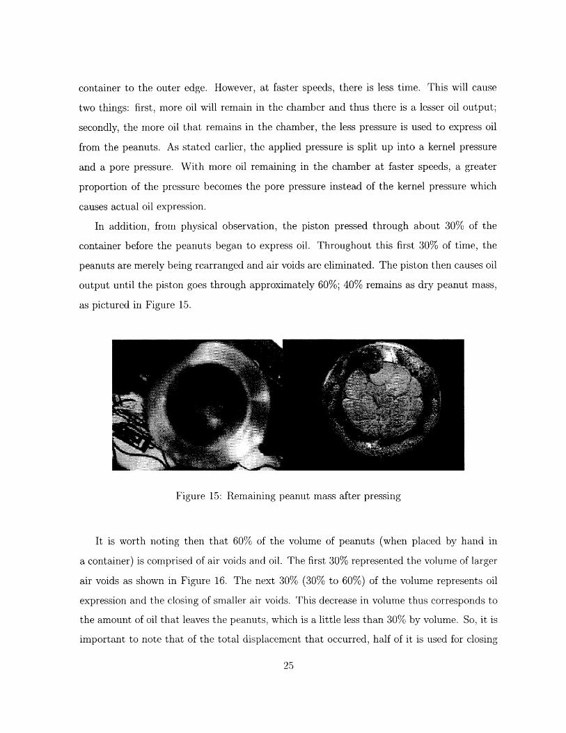
In addition, from physical observation, the piston pressed through about 30% of the
container before the peanuts began to express oil. Throughout this first 30% of time, the
peanuts are merely being rearranged and air voids are eliminated. The piston then causes oil
output until the piston goes through approximately 60%; 40% remains as dry peanut mass,
as pictured in Figure 15.
Figure 15: Remaining peanut mass after pressing
It is worth noting then that 60% of the volume of peanuts (when placed by hand in
a container) is comprised of air voids and oil. The first 30% represented the volume of larger
air voids as shown in Figure 16. The next 30% (30% to 60%) of the volume represents oil
expression and the closing of smaller air voids. This decrease in volume thus corresponds to
the amount of oil that leaves the peanuts, which is a little less than 30% by volume. So, it is
important to note that of the total displacement that occurred, half of it is used for closing
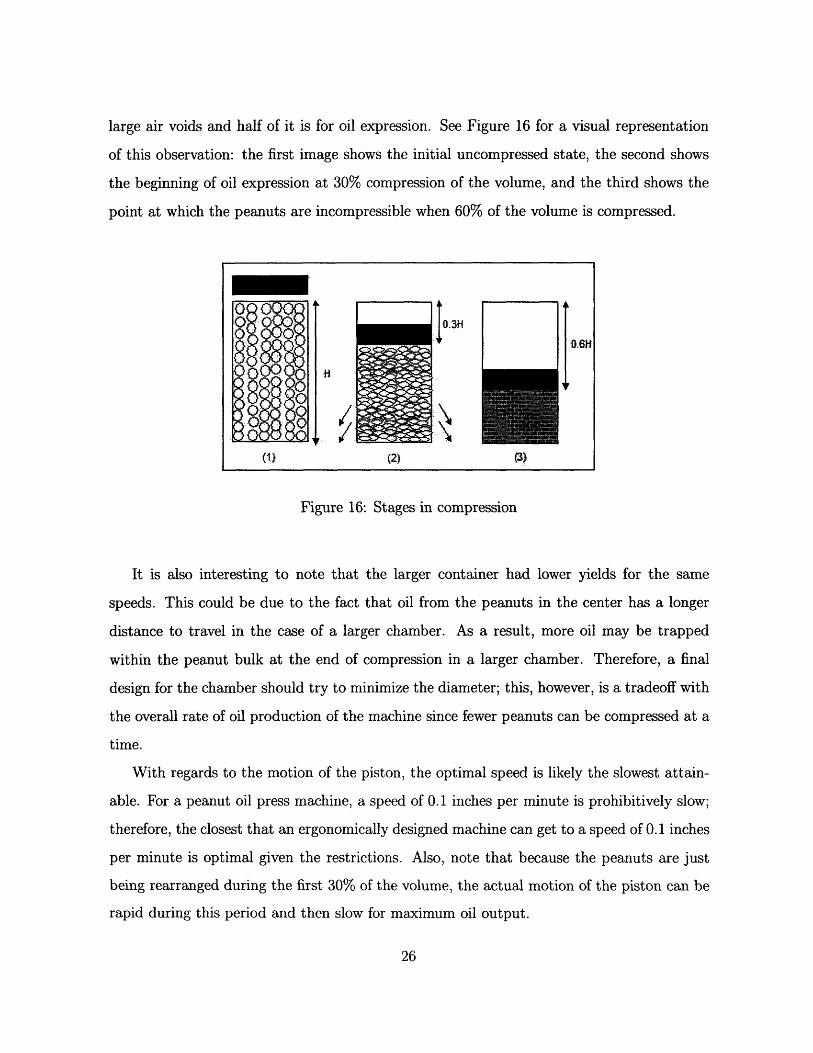
large air voids and half of it is for oil expression. See Figure 16 for a visual representation
of this observation: the first image shows the initial uncompressed state, the second shows
the beginning of oil expression at 30% compression of the volume, and the third shows the
point at which the peanuts are incompressible when 60% of the volume is compressed.
Figure 16: Stages in compression
It is also interesting to note that the larger container had lower yields for the same
speeds. This could be due to the fact that oil from the peanuts in the center has a longer
distance to travel in the case of a larger chamber. As a result, more oil may be trapped
within the peanut bulk at the end of compression in a larger chamber. Therefore, a final
design for the chamber should try to minimize the diameter; this, however, is a tradeoff with
the overall rate of oil production of the machine since fewer peanuts can be compressed at a
time.
With regards to the motion of the piston, the optimal speed is likely the slowest attain-
able. For a peanut oil press machine, a speed of 0.1 inches per minute is prohibitively slow;
therefore, the closest that an ergonomically designed machine can get to a speed of 0.1 inches
per minute is optimal given the restrictions. Also, note that because the peanuts are just
being rearranged during the first 30% of the volume, the actual motion of the piston can be
rapid during this period and then slow for maximum oil output.
I D .3 0.61-1
(1) (2)
IIl
6
I
rF(!) (2)
5.1.2 Force Profile
While the force profile is not necessary to evaluate for the purposes of designing a new
cam, it may be useful in future overall designs of the peanut oil press. With the experiments
in the small container, oil began to be expressed at a force of approximately 2 kN, or a
pressure of 2.5 MPa. The peanuts were incompressible at approximately 12 kN, or a pressure
of 15.1 MPa. For the larger container, oil began to be expressed at a force of approximately
15 kN, or a pressure of 6.6 MPa. The peanuts were incompressible at about 100 kN, or 44.1
MPa. The higher pressures for the larger container likely are because the oil takes longer to
reach the outside of the chamber and thus a larger pressure is needed for any oil expression
to be visually observed. The most valuable result is that oil expression is most significant in
a region of about 3 - 7 MPa.
Figures 12 and 13 also demonstrate that the magnitude of the force increases gradually
during the initial part of compression that increases rapidly at later stages. This reflects the
fact that during most of the compression, the peanuts are compressible due to the presence
of oil and air voids. As the oil is pressed out of the surface of the peanut and all the air is
pushed out of the peanut bulk, there is less and less compressibility that the peanut mass
can withstand. Also, most of the oil leaves the actual peanut in the region where the slope
of the force-displacement is less steep; at steep slopes, most of the pressing likely contributes
to pushing the oil from the surface of the peanuts to outside of the chamber.
These results can then inform a designer of'any peanut oil press as to the pressures
required to express oil from peanuts.
5.2 Proposed Cam Designs
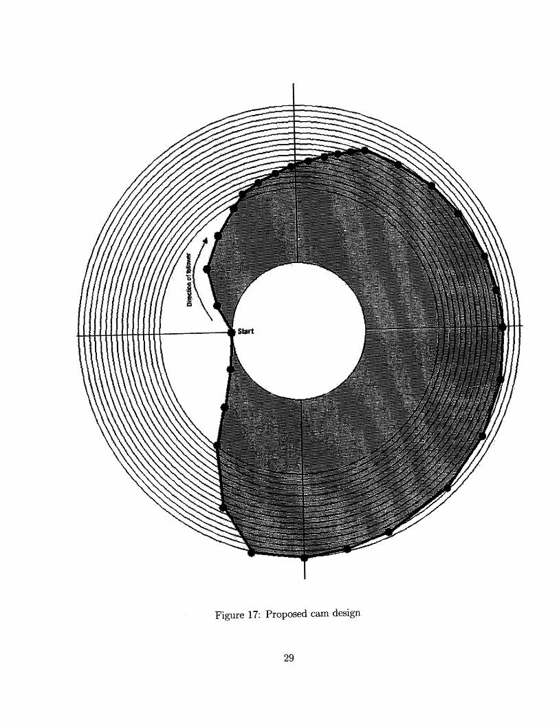
Based on the results, an approximate design for a cam can be created. Figure 17 is a
cam design which would roughly maximize oil output while taking into account human user
preferences. Ideally, a cam that moved at 0.1 inches per minute would give the most oil.
However, since this is unbearingly slow, a design that moves fast in the first stages of pressing
and then slow for the remainder will suffice.
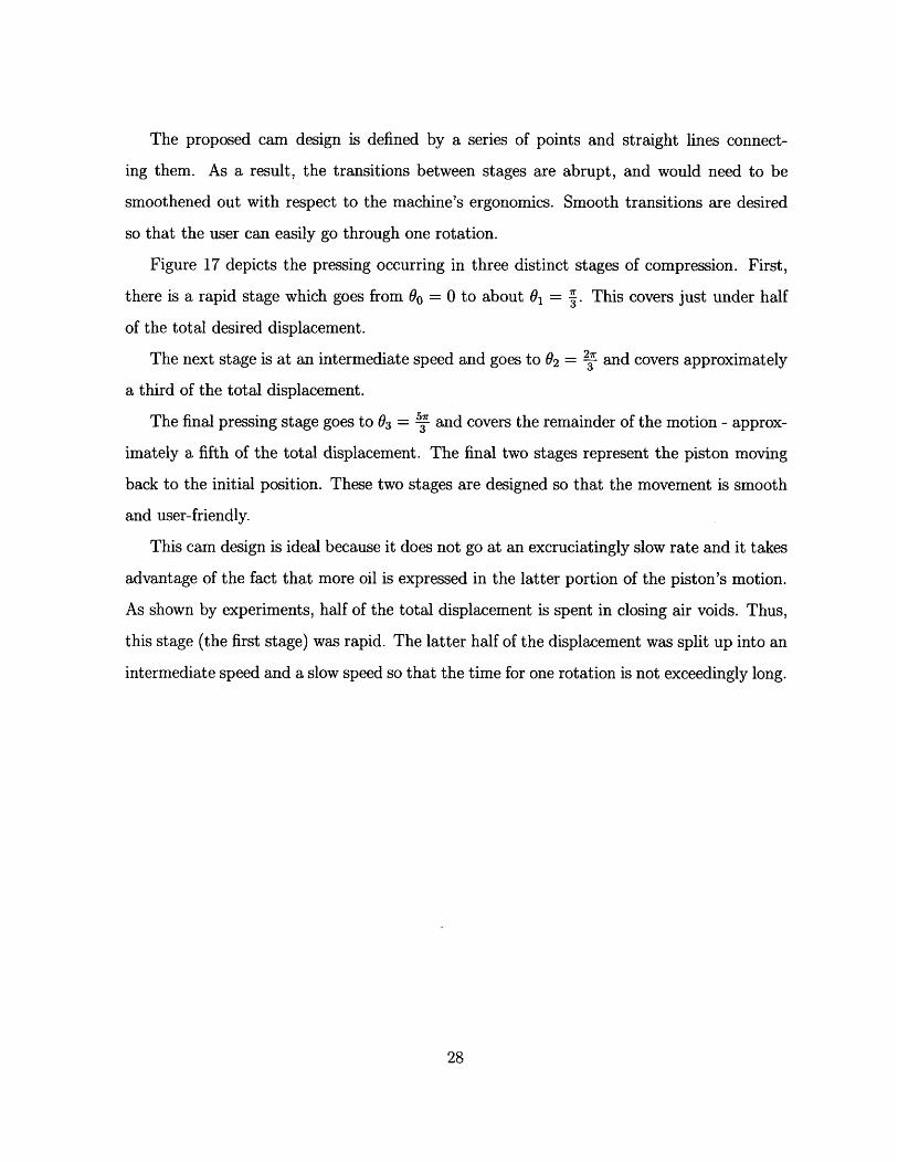
The proposed cam design is defined by a series of points and straight lines connect-
ing them. As a result, the transitions between stages are abrupt, and would need to be
smoothened out with respect to the machine's ergonomics. Smooth transitions are desired
so that the user can easily go through one rotation.
Figure 17 depicts the pressing occurring in three distinct stages of compression. First,
there is a rapid stage which goes from 80 = 0 to about 81 = Z. This covers just under half
of the total desired displacement.
The next stage is at an intermediate speed and goes to 02 = J and covers approximately
a third of the total displacement.
The final pressing stage goes to 03 = E and covers the remainder of the motion - approx-
imately a fifth of the total displacement. The final two stages represent the piston moving
back to the initial position. These two stages are designed so that the movement is smooth
and user-friendly.
This cam design is ideal because it does not go at an excruciatingly slow rate and it takes
advantage of the fact that more oil is expressed in the latter portion of the piston's motion.
As shown by experiments, half of the total displacement is spent in closing air voids. Thus,
this stage (the first stage) was rapid. The latter half of the displacement was split up into an
intermediate speed and a slow speed so that the time for one rotation is not exceedingly long.
Start
Figure 17: Proposed cam design
6 Conclusions and Future Research
The intention of this thesis was to optimize the displacement profile of a peanut pressing
peanuts with respect to the oil expressed from the peanut bulk. The results of the exper-
imentation show that the slower the rate of displacement, the greater the oil yield. This
trend seems to level off at around 0.05 inches per minute. These results roughly correspond
with past literature concerning oil expression from peanuts.
Experimentation also found that there is not a significant decrease in oil output if a faster
speed is used when compressing the first 30% of the volume of peanuts, or 50% of the total
displacement, since this mostly involves rearranging the peanuts. Thus, a cam design was
created that takes advantage of this fact. The proposed cam design results in a rapid motion
for the first half of displacement then a combination of an intermediate speed and a slow
speed for the latter half.
The cam shown in Figure 17 is an approximate rendition of such a design. Thus, the
treadle-powered peanut oil press can likely experience higher oil outputs if the cam is de-
signed in the aforementioned manner.
Future research should utilize the results of this thesis and determine a design for the cam
that corresponds with the newest design for the treadle-powered peanut oil press machine.
The cam should be designed with two specifications in mind: first, the optimal displacement
profile; and second, user friendliness. Because there is efficiency loss in the machine, the
oil output will be less than what was demonstrated by the Instron machine. Therefore, oil
output studies should be conducted with the overall machine to see if yields can come close
to those experimentally observed.
After integration of the cam into the final machine, the oil press should be tested with
human users to test its ergonomics. The smoothness of the cam design is a factor in the
user's experience on the machine.
Ultimately, a functional peanut oil press machine should be tested in the field in villages
in Africa to determine feasibility of manufacturing and design. In addition, the ability to
integrate the machine into the activities of individual households is critical to the product's
success. Further work should be done to promote manufacturing and use of the machine in
communities so that the technology becomes self sustainable.
References
[1] Adeeko, K.A. and 0. O. Ajibola. "Processing factors affecting yield and quality of
mechanically expressed groundnut oil." Journal of Agricultural Engineering Research.
Vol. 45, pg. 31-43. 1990.
[2] Goodrum, J.W., "Review of Biodiesel Research at University of Georgia," Liquid Fuels
and Industrial Products from Renewable Resources - Proceedings of the Third Liquid
Fuels Conference, Nashville, Tenn., Sept. 15-17, 1996.
[3] Hamzat, K.O. and B. Clarke. "Prediction of oil yield from groundnuts using the concept
of quasi-equilibrium oil yield." Journal of Agricultural Engineering Research. Vol. 55, p.
79-87. 1993.
[4] Hynd, Alison, and Amy Smith. Meeting a Pressing Need. D-Lab Case Study. 20 October
2004.
[5] Khan, L. M. and M.A. Hanna. "Expression of oil from oilseeds - a review."
Journal of Agricultural Engineering Research. Vol. 28, pg. 495-503. 1983.
[6] Li, Vivian, Marta Luczynska, Nawar Najeeb, and Anne Romeo. Peanut Oil Press: Final
Report. MIT D-Lab: Design. Spring 2006.
[7] Mrema, G.C. and P.B. McNulty. "Mathematical model of mechanical oil expression from
oilseeds." Journal of Agricultural Engineering Research. Vol. 31, pg. 261-370. 1985.
[8] Owolarafe, O.K., A.T. Adegunloye, and 0.0. Ajibola. "The effects of some processing
conditions on oil point pressure of locust bean." Journal of Food Process Engineering.
Vol. 26, pg. 489-497. 2003.
[9] Oyinlola, A., A. Ojo, and L.O. Adekoya. "Development of a laboratory model screw
press for peanut oil expression." Journal of Food Engineering. Vol. 64, pg. 221-27. 2004.
[10] Smillie, Ian. Mastering the Machine Revisited: Poverty, Aid, and Technology. London:
ITDG Publishing, 2000.
[11] Smith, Amy. Design Challenge: Foot-Powered Oil Press. Spring 2006.
http://web.mit.edu/d-lab/assignment_files/OilPress.pdf
[12] Smith, Amy. Personal Photograph. August 2005.
[13] Sukumaran, C.R. and B. P. N. Singh. "Compression of a Bed of Rapeseeds: The Oil-
point." Journal of Agricultural Engineering Research. Vol. 42, pg. 77-84. 1989.
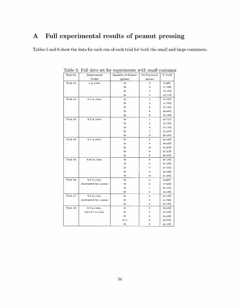
A Full experimental results of peanut pressing
Tables 5 and 6 show the data for each run of each trial for both the small and large containers.
Table 5: Full data set for experiments with small containerTrial No. Displacement Quantity of Peanuts Oil Expressed % Yield
Profile (grams) (grams)
Trial Al 1 in./min. 33 3 9.09%
34 4 11.76%
33 5 15.15%
34 5 14.71%
Trial A2 0.5 in./min. 33 5 15.15%
34 4 11.76%
33 6 18.18%
29 6 20.69%
33 6 18.18%
Trial A3 0.2 in./min. 34 5 14.71%
33 5 15.15%
33 4 12.12%
33 7 21.21%
34 8 23.53%
Trial A4 0.1 in./min. 33 8 24.24%
31 9 29.03%
32 10 31.25%
33 9 27.27%
34 9 26.47%
Trial A5 0.05 in./min. 32 9 28.13%
33 9 27.27%
33 7 21.21%
33 8 24.24%
32 10 31.25%
Trial A6 0.2 in./min. 34 3 8.82%
interrupted by a pause 34 6 17.65%
33 7 21.21%
33 6 18.18%
Trial A7 0.5 in./min. 33 5 15.15%
interrupted by a pause 34 4 11.76%
33 6 18.18%
Trial A8 0.5 in./min., 32 5 15.63%
then 0.1 in./min. 33 9 27.27%
33 8 24.24%
31.5 9 28.57%
32 9 28.13%
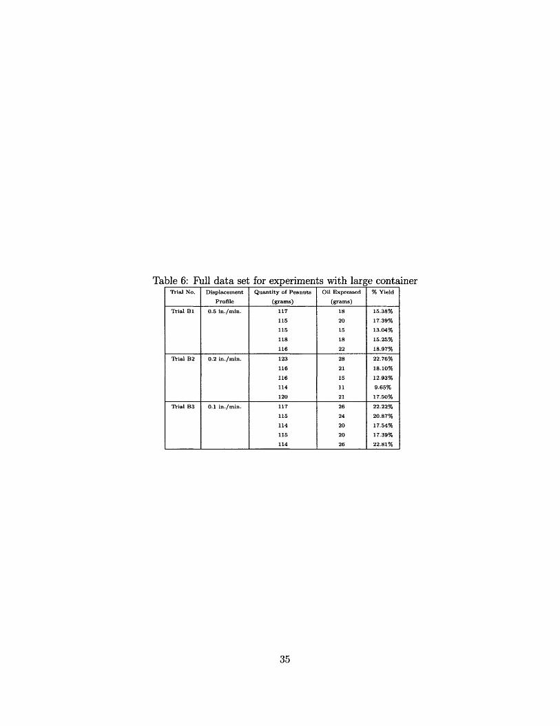
Table 6: Full data set for experiments with large containerTrial No. Displacement Quantity of Peanuts Oil Expressed % Yield
Profile (grams) (grams)
Trial B1 0.5 in./min. 117 18 15.38%
115 20 17.39%
115 15 13.04%
118 18 15.25%
116 22 18.97%
Trial B2 0.2 in./min. 123 28 22.76%
116 21 18.10%
116 15 12.93%
114 11 9.65%
120 21 17.50%
Trial B3 0.1 in./min. 117 26 22.22%
115 24 20.87%
114 20 17.54%
115 20 17.39%
114 26 22.81%