Maverick Technical Manual
120
Maverick Equipment Manufacturing, Inc. U.S.A. - Product Technical Manual Page 1 TD-000-E04 Maverick Hydraulic Hammers Service and Technical Manual
-
Upload
maverick-hammers -
Category
Documents
-
view
420 -
download
15
description
Maverick Technical Manual
Transcript of Maverick Technical Manual
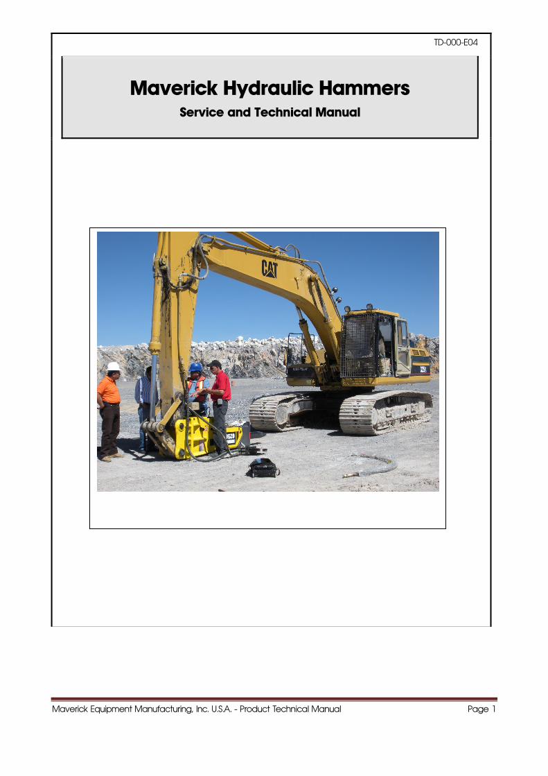
Maverick Equipment Manufacturing, Inc. U.S.A. - Product Technical Manual Page 1
TD-000-E04
Maverick Hydraulic Hammers
Service and Technical Manual
Maverick Equipment Manufacturing, Inc. U.S.A. - Product Technical Manual Page 2
C O N T E N T S
Maverick Equipment Manufacturing, Inc. U.S.A. - Product Technical Manual Page 3
1. About the Hammer
1.1 Definition (mechanism) ............................................................................................................................................. 8
1.2 General composition of the Hammer for use ........................................................................................... 8
1.3 General classification of the Hammer ..................................................................................................... 9
2. General specifications
2.1 Standard technical specifications .................................................................................................................. 11
2.2 Dimensions
2.2.1Tool(Rod) ....................................................................................................................................................................... 16
2.2.2 Main body(Hammer) .......................................................................................................................................... 19
2.2.3 Bracket(Housing)
(1) Silenced type (S-type) ......................................................................................................................... 26
(2) Top type (T-type) ..................................................................................................................................... 30
(3) Side type (H-type) ................................................................................................................................... 33
(4) Back hoe type (B-type) ....................................................................................................................... 35
(5) Uniram type (U-type) ............................................................................................................................. 36
2.2.4 Top plate ..................................................................................................................................................................... 37
3. Structural view of the hammers
3.1 350, 400, 500, 750, 1000, 1500, 2250, 3250 .............................................................................. 43
3.2 6250 ................................................................................................................................................................................ 44
3.3 4750, 5250, 8250, 9250 .................................................................................................................................... 45
4. Functions of the main components
4.1 350, 400, 500, 750, 1000, 1500, 2250, 3250 ...................................................................................... 47
4.2 6250 ................................................................................................................................................................................ 48
4.3 4750, 5250, 8250, 9250 .................................................................................................................................... 49
4.4 Valve system ............................................................................................................................................................. 50
5. Principle of operation
5.1 350, 400, 500, 750, 1000, 1500, 2250, 3250, 6250
Introduction .......................................................................................................................................................... 52
Piston start up (Return stroke) ............................................................................................................... 53
Valve changing ................................................................................................................................................. 54
Impact stroke ...................................................................................................................................................... 55
5.2 4750, 5250, 8250, 9250
Introduction ..........................................................................................................................................................57
Maverick Equipment Manufacturing, Inc. U.S.A. - Product Technical Manual Page 4
Maverick Hammers - U.S.A.
C O N T E N T S
6.16 Disassembly and assembly of the valve and valve plug ......................................................... 77
6.17 Disassembly and assembly of the valve housing ........................................................................... 78
6.18 Disassembly and assembly of the accumulator adjuster ......................................................... 79
6.19 Disassembly and assembly of the accumulator cover ........................................................... 80
6.20 Disassembly and assembly of the accumulator bottom ............................................................ 81
6.21 Disassembly and assembly of the cylinder adjuster ....................................................................... 82
6.22 Disassembly and assembly of the air vent ........................................................................................... 83
6.23 Disassembly and assembly of the seal in the seal housing ...................................................... 84
6.24 Disassembly and assembly of the seal in the cylinder ................................................................. 85
6.25 Disassembly and assembly of the silencing parts ............................................................................ 86
7. Torque references
7.1 350, 400, 500 ................................................................................................................................................................ 88
7.2 750, 1000, 1500, 2250, 3250 ............................................................................................................................. 89
7.3 4750, 5250, 6250, 8250, 9250 .......................................................................................................................... 90
8. Valve adjuster control ........................................................................................................................................................ 92
9. Tool
9.1 Replacement of the tool .................................................................................................................................. 94
9.2 How to use tools properly .................................................................................................................................... 95
10. How to charge N2 gas
10.1 Gas charging to the back-head ........................................................................................................... 100
10.2. Gas charging to the accumulator. ........................................................................................................ 102
Maverick Equipment Manufacturing, Inc. U.S.A. - Product Technical Manual Page 5
11.. AABBOOUUTT TTHHEE HHaammmmeerr
Maverick Equipment Manufacturing, Inc. U.S.A. - Product Technical Manual Page 6
1.1 Definition ( mechanism )
The Hammer is the hammering implement using movement energy transformed from
electric, hydraulic, pneumatic energy, etc each by mechanical tools, hydraulic circuit,
pneumatic circuit mechanism.
The Hammer is used for various purposes, for example, to crush and demolish rocks in
quarries and mines or for building dismantling works, pavement breaking and so on with
mounting it on the excavator.
The Hammer was first developed for pneumatic system using only compressed air. After
then, it has been developed for hydraulic system using hydraulic oil supported from the
hydraulic pump of the excavator and now being in use with mixture system of nitrogen gas
and hydraulic pressure as designed for less consuming of the hydraulic oil, high efficiency
and more lightening in weight in order to minimize any possible damage on the
excavator’s unit.
(hydraulic pump)
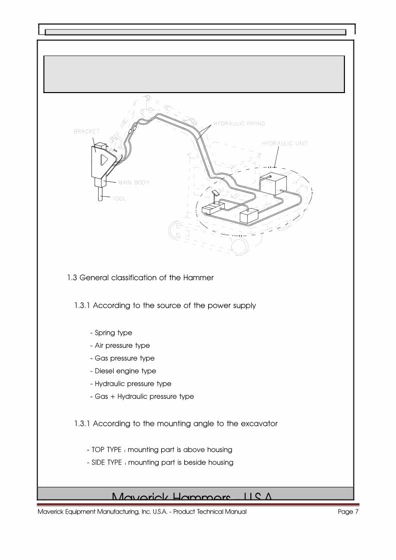
1.2 General composition of the Hammer for use
A) Main body parts
B) Piping parts
C) Bracket parts
D) Hydraulic unit (Power units)
Maverick Equipment Manufacturing, Inc. U.S.A. - Product Technical Manual Page 7
1.3 General classification of the Hammer
1.3.1 According to the source of the power supply
- Spring type
- Air pressure type
- Gas pressure type
- Diesel engine type
- Hydraulic pressure type
- Gas + Hydraulic pressure type
1.3.1 According to the mounting angle to the excavator
- TOP TYPE : mounting part is above housing
- SIDE TYPE : mounting part is beside housing
Maverick Hammers - U S A
Maverick Equipment Manufacturing, Inc. U.S.A. - Product Technical Manual Page 8
22..GGEENNEERRAALL SSPPEECCIIFFIICCAATTIIOONNSS
Maverick Equipment Manufacturing, Inc. U.S.A. - Product Technical Manual Page 9
Maverick Hammers - U.S.A.
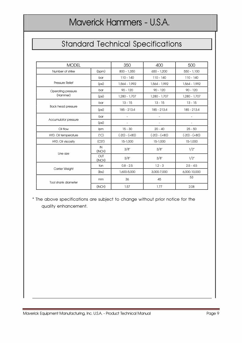
Standard Technical Specifications
MODEL 350 400 500 Number of strike (bpm) 800 - 1,350 650 - 1,200 550 - 1,100
Pressure Relief
bar 110 - 140 110 - 140 110 - 140
(psi) 1,564 - 1,992 1,564 - 1,992 1,564 - 1,992
Operating pressure (Hammer)
bar 90 - 120 90 - 120 90 - 120
(psi) 1,280 - 1,707 1,280 - 1,707 1,280 - 1,707
Back head pressure bar 13 - 15 13 - 15 13 - 15
(psi) 185 - 213.4 185 - 213.4 185 - 213.4
Accumulator pressure bar - - -
(psi) - - -
Oil flow lpm 15 - 30 20 - 40 25 - 50
HYD. Oil temperature (°C) (-20) - (+80) (-20) - (+80) (-20) - (+80)
HYD. Oil viscosity (CST) 15-1,000 15-1,000 15-1,000
Line size
IN (INCH)
3/8“ 3/8“ 1/2“
OUT (INCH)
3/8“ 3/8“ 1/2“
Carrier Weight ton 0.8 - 2.5 1.2 - 3 2.5 - 4.5
(lbs) 1,600-5,000 3,000-7,000 6,000-10,000
Tool shank diameter mm 36 45
53
(INCH) 1.57 1.77 2.08
* The above specifications are subject to change without prior notice for the
quality enhancement.
Maverick Equipment Manufacturing, Inc. U.S.A. - Product Technical Manual Page 10
Maverick Hammers - U.S.A.
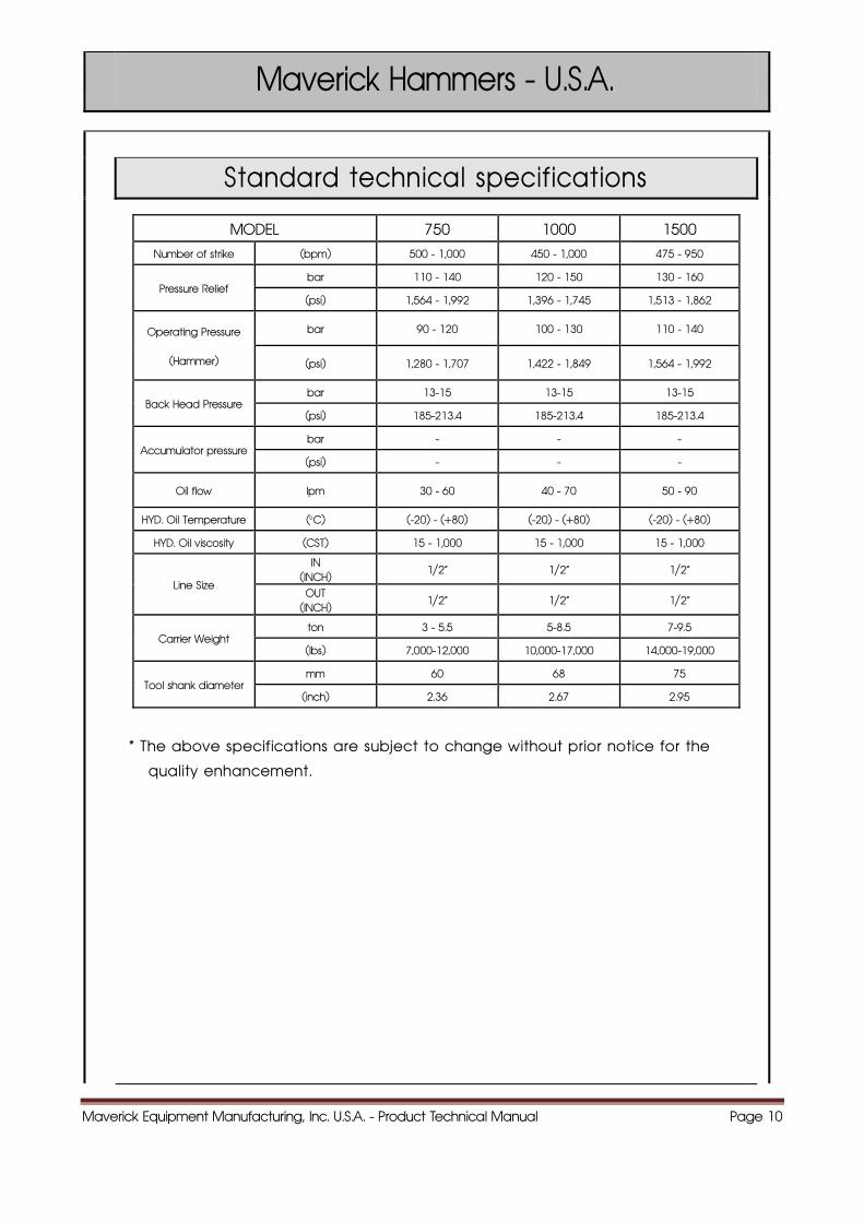
Standard technical specifications
MODEL 750 1000 1500
Number of strike (bpm) 500 - 1,000 450 - 1,000 475 - 950
Pressure Relief bar 110 - 140 120 - 150 130 - 160
(psi) 1,564 - 1,992 1,396 - 1,745 1,513 - 1,862
Operating Pressure
(Hammer)
bar 90 - 120 100 - 130 110 - 140
(psi) 1,280 - 1,707 1,422 - 1,849 1,564 - 1,992
Back Head Pressure bar 13-15 13-15 13-15
(psi) 185-213.4 185-213.4 185-213.4
Accumulator pressure bar - - -
(psi) - - -
Oil flow lpm 30 - 60 40 - 70 50 - 90
HYD. Oil Temperature (°C) (-20) - (+80) (-20) - (+80) (-20) - (+80)
HYD. Oil viscosity (CST) 15 - 1,000 15 - 1,000 15 - 1,000
Line Size
IN (INCH)
1/2“ 1/2“ 1/2“
OUT (INCH)
1/2“ 1/2“ 1/2“
Carrier Weight ton 3 - 5.5 5-8.5 7-9.5
(lbs) 7,000-12,000 10,000-17,000 14,000-19,000
Tool shank diameter mm 60 68 75
(inch) 2.36 2.67 2.95
* The above specifications are subject to change without prior notice for the
quality enhancement.
Maverick Equipment Manufacturing, Inc. U.S.A. - Product Technical Manual Page 11
Maverick Hammers - U.S.A.
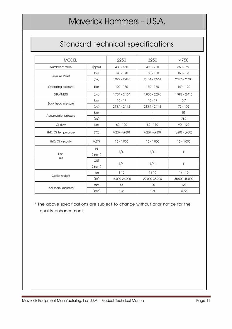
Standard technical specifications
MODEL 2250 3250 4750
Number of strike (bpm) 480 - 850 480 - 780 350 - 750
Pressure Relief bar 140 - 170 150 - 180 160 - 190
(psi) 1,992 - 2,418 2,134 - 2,561 2,276 - 2,703
Operating pressure bar 120 - 150 130 - 160 140 - 170
(HAMMER) (psi) 1,707 - 2,134 1,850 - 2,276 1,992 - 2,418
Back head pressure bar 15 - 17 15 - 17 5-7
(psi) 213.4 - 241.8 213.4 - 241.8 73 - 102
Accumulator pressure bar - - 55
(psi) - - 782
Oil flow lpm 60 - 100 80 - 110 90 - 120
HYD. Oil temperature (°C) (-20) - (+80) (-20) - (+80) (-20) - (+80)
HYD. Oil viscosity (cST) 15 - 1,000 15 - 1,000 15 - 1,000
Line size
IN 3/4“ 3/4“ 1"
( inch )
OUT 3/4“ 3/4“ 1"
( inch )
Carrier weight ton 8-12 11-19 14 - 19
(lbs) 16,000-24,000 22,000-38,000 35,000-48,000
Tool shank diameter mm 85 100 120
(inch) 3.35 3.94 4.72
* The above specifications are subject to change without prior notice for the
quality enhancement.
Maverick Equipment Manufacturing, Inc. U.S.A. - Product Technical Manual Page 12
Maverick Hammers - U.S.A.
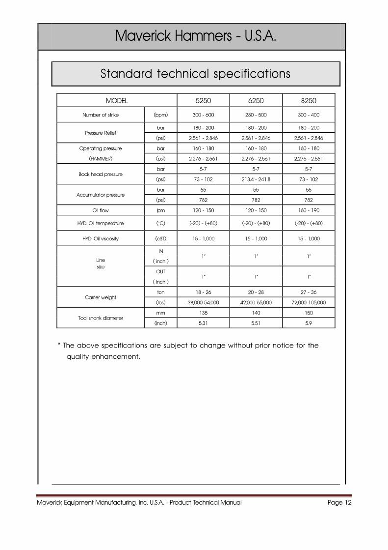
Standard technical specifications
MODEL 5250 6250 8250
Number of strike (bpm) 300 - 600 280 - 500 300 - 400
Pressure Relief bar 180 - 200 180 - 200 180 - 200
(psi) 2,561 - 2,846 2,561 - 2,846 2,561 - 2,846
Operating pressure bar 160 - 180 160 - 180 160 - 180
(HAMMER) (psi) 2,276 - 2,561 2,276 - 2,561 2,276 - 2,561
Back head pressure bar 5-7 5-7 5-7
(psi) 73 - 102 213.4 - 241.8 73 - 102
Accumulator pressure bar 55 55 55
(psi) 782 782 782
Oil flow lpm 120 - 150 120 - 150 160 - 190
HYD. Oil temperature (°C) (-20) - (+80) (-20) - (+80) (-20) - (+80)
HYD. Oil viscosity (cST) 15 - 1,000 15 - 1,000 15 - 1,000
Line size
IN 1“ 1“ 1“
( inch )
OUT 1“ 1“ 1“
( inch )
Carrier weight ton 18 - 26 20 - 28 27 - 36
(lbs) 38,000-54,000 42,000-65,000 72,000-105,000
Tool shank diameter mm 135 140 150
(inch) 5.31 5.51 5.9
* The above specifications are subject to change without prior notice for the
quality enhancement.
Maverick Equipment Manufacturing, Inc. U.S.A. - Product Technical Manual Page 13
Maverick Hammers - U.S.A.
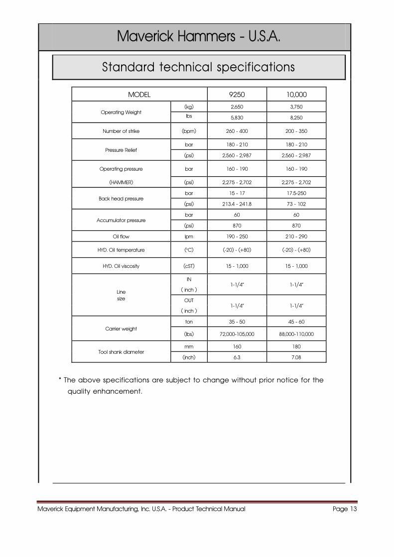
Standard technical specifications
MODEL 9250 10,000
Operating Weight (kg) 2,650 3,750
lbs 5,830 8,250
Number of strike (bpm) 260 - 400 200 - 350
Pressure Relief bar 180 - 210 180 - 210
(psi) 2,560 - 2,987 2,560 - 2,987
Operating pressure bar 160 - 190 160 - 190
(HAMMER) (psi) 2,275 - 2,702 2,275 - 2,702
Back head pressure bar 15 - 17 17.5-250
(psi) 213.4 - 241.8 73 - 102
Accumulator pressure bar 60 60
(psi) 870 870
Oil flow lpm 190 - 250 210 - 290
HYD. Oil temperature (°C) (-20) - (+80) (-20) - (+80)
HYD. Oil viscosity (cST) 15 - 1,000 15 - 1,000
Line size
IN 1-1/4“ 1-1/4“
( inch )
OUT 1-1/4“ 1-1/4“
( inch )
Carrier weight ton 35 - 50 45 - 60
(lbs) 72,000-105,000 88,000-110,000
Tool shank diameter mm 160 180
(inch) 6.3 7.08
* The above specifications are subject to change without prior notice for the
quality enhancement.

Maverick Equipment Manufacturing, Inc. U.S.A. - Product Technical Manual Page 14
Maverick Hammers - U.S.A.
Dimensions - Tool -
BLUNT CONICAL WEDGE MOIL POINT
model 350 400
standard BLUNT CONICAL WEDGE MOIL BLUNT CONICAL WEDGE MOIL
Length (mm) 400 400 400 400 460 460 460 460
Weight ( kg ) 3 2.8 2.9 2.8 5.4 5 5.2 5
Diameter (mm)
Φ36 Φ36 Φ36 Φ36 Φ45 Φ45 Φ45 Φ45
model 500 750
standard BLUNT CONICAL WEDGE MOIL BLUNT CONICAL WEDGE MOIL
Length (mm) 500 500 500 500 500 500 500 500
Weight (kg) 8.1 7.2 7.7 7.4 10.1 8.9 9.5 9.1
Diameter (mm)
Φ53 Φ53 Φ53 Φ53 Φ60 Φ60 Φ60 Φ60
model 1000 1500
standard BLUNT CONICAL WEDGE MOIL BLUNT CONICAL WEDGE MOIL
Length (mm) 690 690 690 690 750 750 750 750
Weight (kg) 18.7 17.1 17.9 17.4 24.7 22.9 23.5 22.8
Diameter (mm)
Φ68 Φ68 Φ68 Φ68 Φ75 Φ75 Φ75 Φ75
Maverick Equipment Manufacturing, Inc. U.S.A. - Product Technical Manual Page 15
Maverick Hammers - U.S.A.
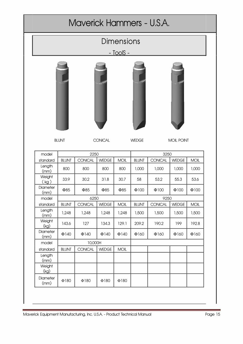
Dimensions - ToolS -
BLUNT CONICAL WEDGE MOIL POINT
model 2250 3250
standard BLUNT CONICAL WEDGE MOIL BLUNT CONICAL WEDGE MOIL
Length (mm)
800 800 800 800 1,000 1,000 1,000 1,000
Weight ( kg )
33.9 30.2 31.8 30.7 58 53.2 55.3 53.6
Diameter (mm)
Φ85 Φ85 Φ85 Φ85 Φ100 Φ100 Φ100 Φ100
model 6250 9250
standard BLUNT CONICAL WEDGE MOIL BLUNT CONICAL WEDGE MOIL
Length (mm)
1,248 1,248 1,248 1,248 1,500 1,500 1,500 1,500
Weight (kg)
143.6 127 134.3 129.1 209.2 190.2 199 192.8
Diameter (mm)
Φ140 Φ140 Φ140 Φ140 Φ160 Φ160 Φ160 Φ160
model 10,000H standard BLUNT CONICAL WEDGE MOIL Length (mm)
Weight (kg)
Diameter (mm)
Φ180 Φ180 Φ180 Φ180
Maverick Equipment Manufacturing, Inc. U.S.A. - Product Technical Manual Page 16
Maverick Hammers - U.S.A.
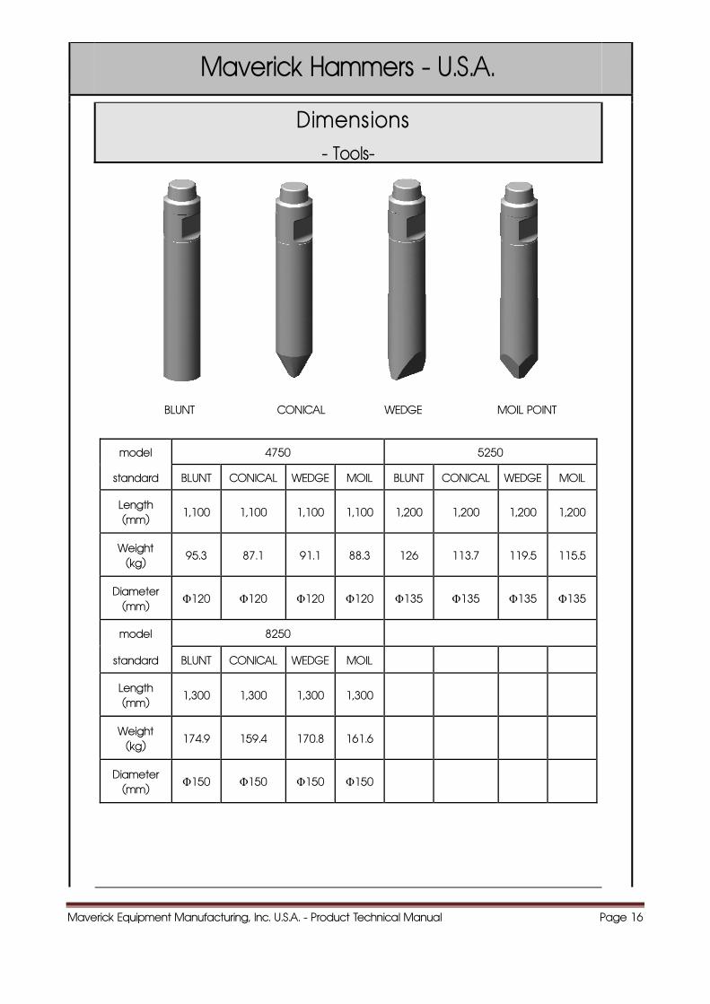
Dimensions - Tools-
BLUNT CONICAL WEDGE MOIL POINT
model 4750 5250
standard BLUNT CONICAL WEDGE MOIL BLUNT CONICAL WEDGE MOIL
Length (mm)
1,100 1,100 1,100 1,100 1,200 1,200 1,200 1,200
Weight (kg)
95.3 87.1 91.1 88.3 126 113.7 119.5 115.5
Diameter (mm)
Φ120 Φ120 Φ120 Φ120 Φ135 Φ135 Φ135 Φ135
model 8250
standard BLUNT CONICAL WEDGE MOIL
Length (mm)
1,300 1,300 1,300 1,300
Weight (kg)
174.9 159.4 170.8 161.6
Diameter (mm)
Φ150 Φ150 Φ150 Φ150
Maverick Equipment Manufacturing, Inc. U.S.A. - Product Technical Manual Page 17
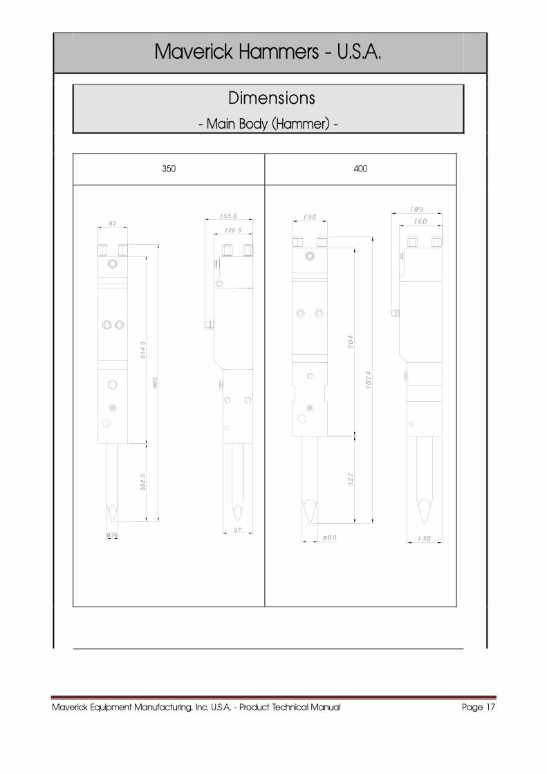
Maverick Hammers - U.S.A.
Dimensions - Main Body (Hammer) -
350 400
Maverick Equipment Manufacturing, Inc. U.S.A. - Product Technical Manual Page 18
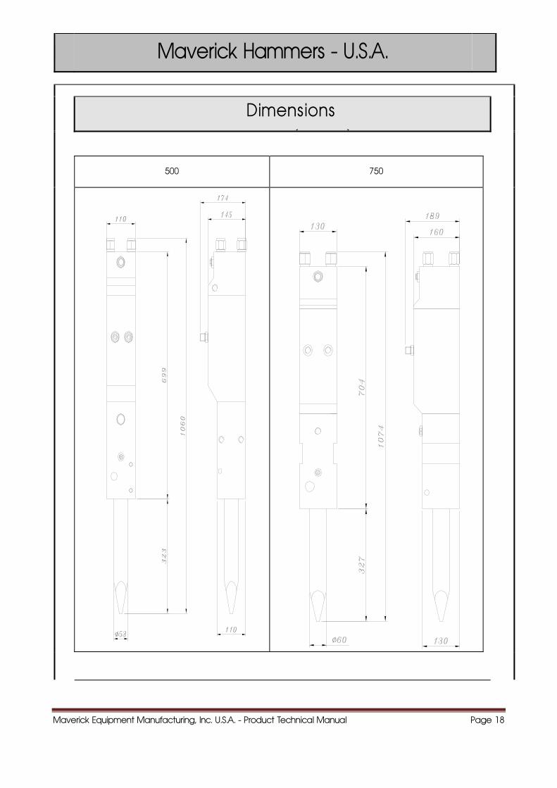
Maverick Hammers - U.S.A.
Dimensions ( )
500 750
Maverick Equipment Manufacturing, Inc. U.S.A. - Product Technical Manual Page 19
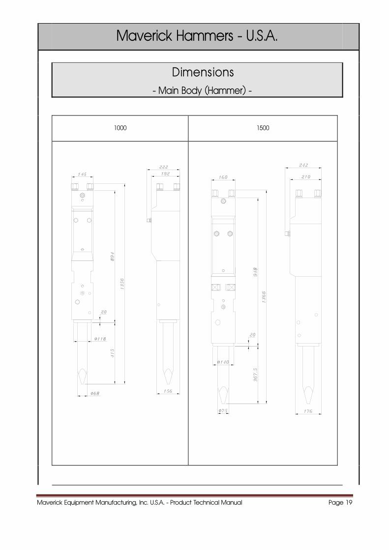
Maverick Hammers - U.S.A.
Dimensions - Main Body (Hammer) -
1000 1500
Maverick Equipment Manufacturing, Inc. U.S.A. - Product Technical Manual Page 20
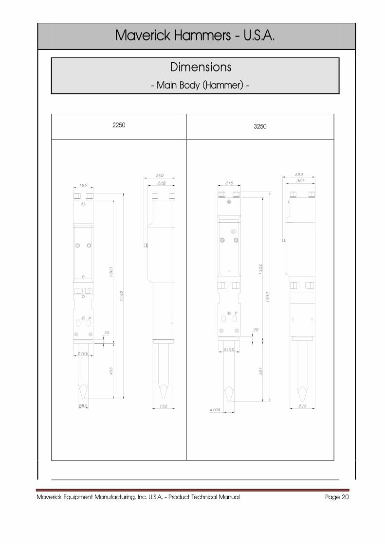
Maverick Hammers - U.S.A.
Dimensions - Main Body (Hammer) -
2250 3250
Maverick Equipment Manufacturing, Inc. U.S.A. - Product Technical Manual Page 21
Maverick Hammers - U.S.A.
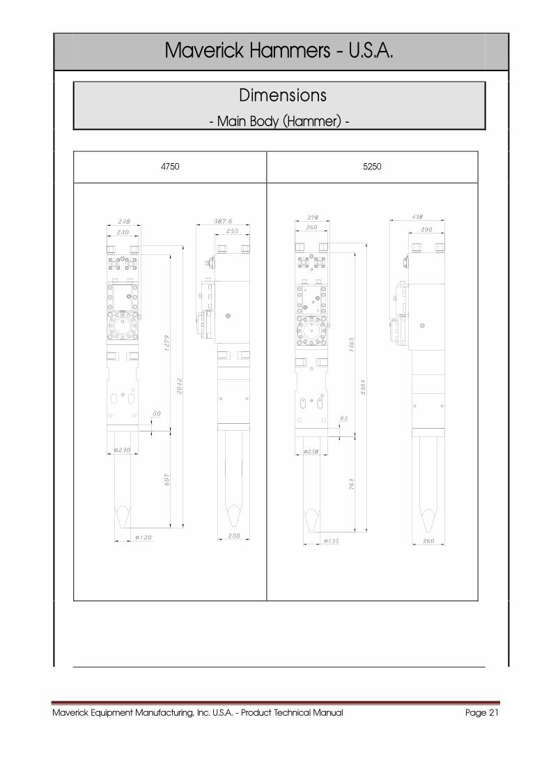
Dimensions - Main Body (Hammer) -
4750 5250
Maverick Equipment Manufacturing, Inc. U.S.A. - Product Technical Manual Page 22
Maverick Hammers - U.S.A.
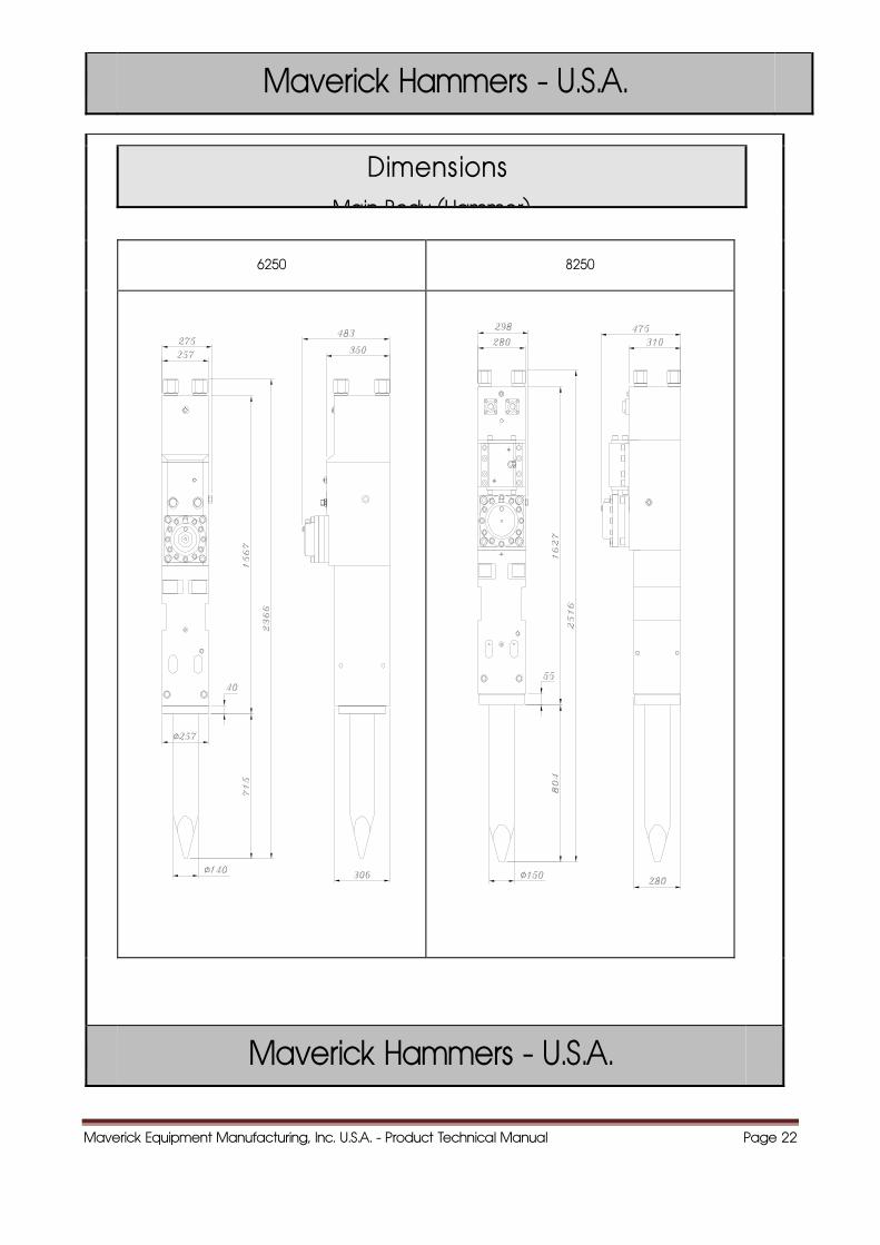
Dimensions Main Body (Hammer)
6250 8250
Maverick Hammers - U.S.A.
Maverick Equipment Manufacturing, Inc. U.S.A. - Product Technical Manual Page 23
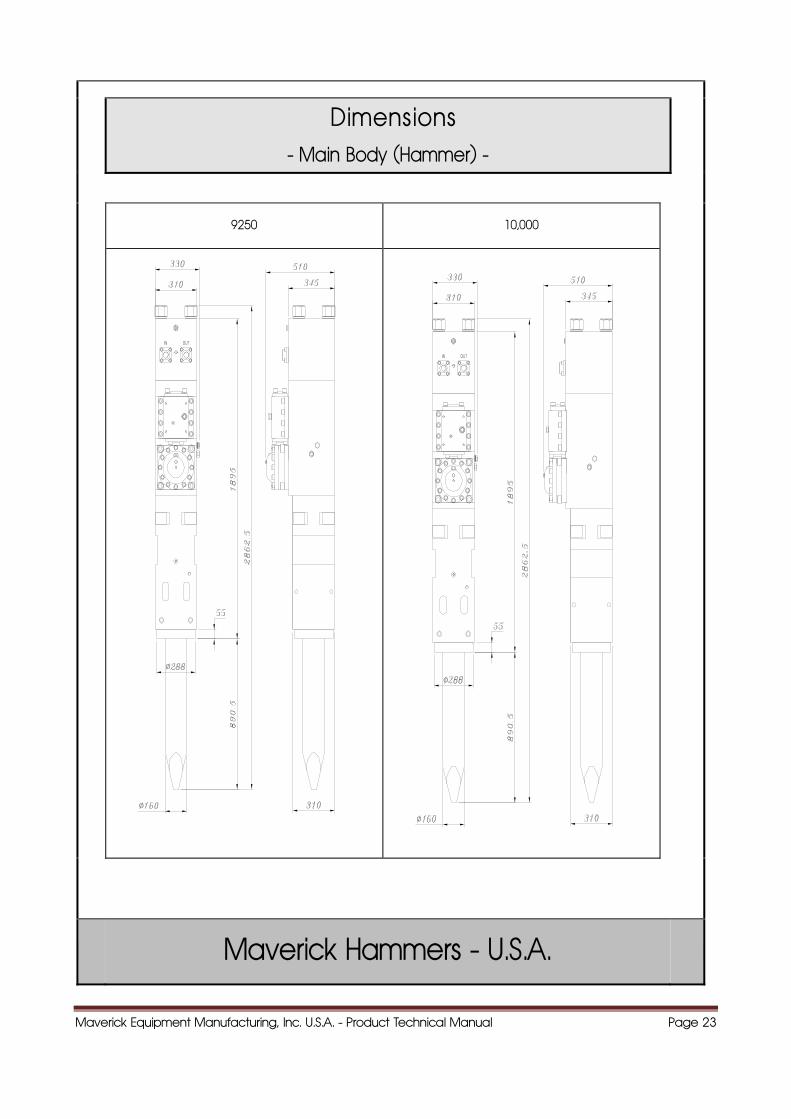
Dimensions - Main Body (Hammer) -
9250 10,000
Maverick Hammers - U.S.A.
Maverick Equipment Manufacturing, Inc. U.S.A. - Product Technical Manual Page 24
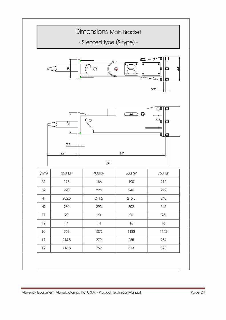
Dimensions Main Bracket
- Silenced type (S-type) -
(mm) 350HSP 400HSP 500HSP 750HSP
B1 175 186 190 212
B2 220 228 246 272
H1 202.5 211.5 215.5 240
H2 280 293 302 345
T1 20 20 20 25
T2 14 14 16 16
L0 963 1073 1133 1142
L1 214.5 279 285 284
L2 716.5 762 813 823
Maverick Equipment Manufacturing, Inc. U.S.A. - Product Technical Manual Page 25
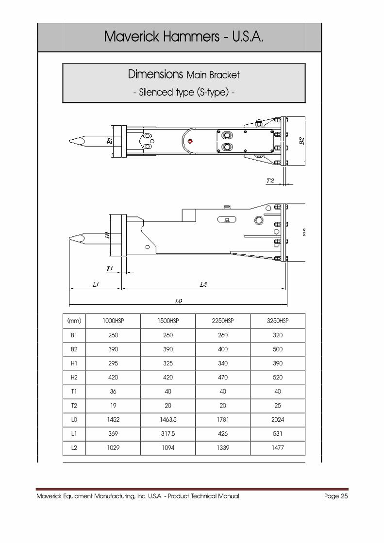
Maverick Hammers - U.S.A.
Dimensions Main Bracket
- Silenced type (S-type) -
(mm) 1000HSP 1500HSP 2250HSP 3250HSP
B1 260 260 260 320
B2 390 390 400 500
H1 295 325 340 390
H2 420 420 470 520
T1 36 40 40 40
T2 19 20 20 25
L0 1452 1463.5 1781 2024
L1 369 317.5 426 531
L2 1029 1094 1339 1477
Maverick Equipment Manufacturing, Inc. U.S.A. - Product Technical Manual Page 26
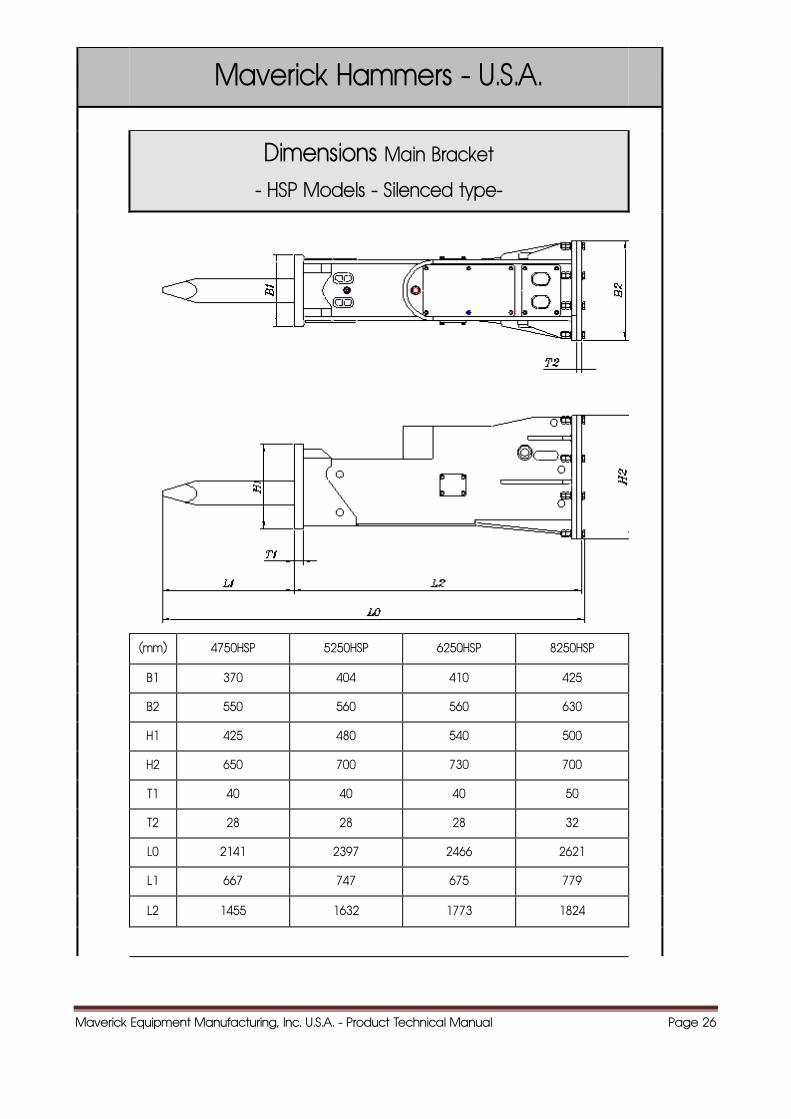
Maverick Hammers - U.S.A.
Dimensions Main Bracket
- HSP Models - Silenced type-
(mm) 4750HSP 5250HSP 6250HSP 8250HSP
B1 370 404 410 425
B2 550 560 560 630
H1 425 480 540 500
H2 650 700 730 700
T1 40 40 40 50
T2 28 28 28 32
L0 2141 2397 2466 2621
L1 667 747 675 779
L2 1455 1632 1773 1824
Maverick Equipment Manufacturing, Inc. U.S.A. - Product Technical Manual Page 27
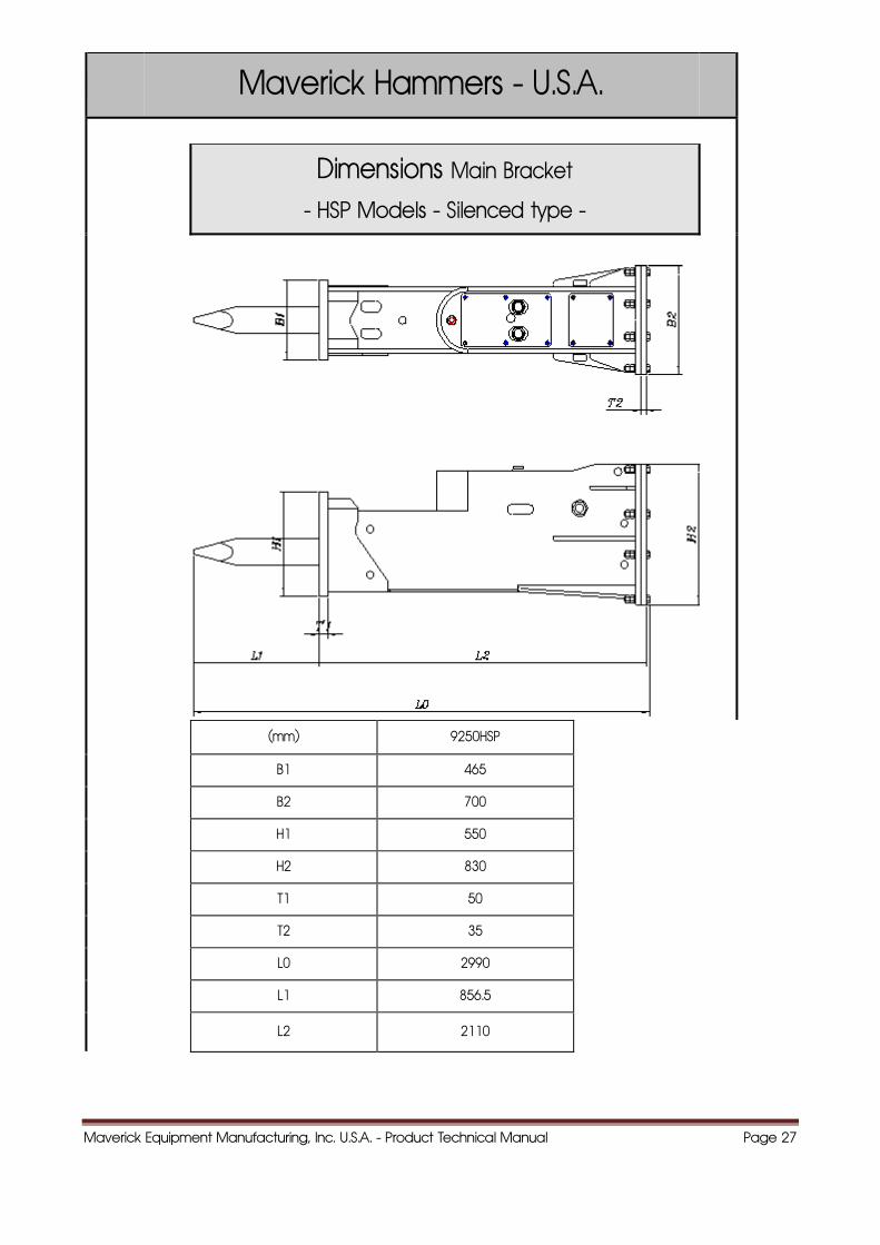
Maverick Hammers - U.S.A.
Dimensions Main Bracket
- HSP Models - Silenced type -
(mm) 9250HSP
B1 465
B2 700
H1 550
H2 830
T1 50
T2 35
L0 2990
L1 856.5
L2 2110
Maverick Equipment Manufacturing, Inc. U.S.A. - Product Technical Manual Page 28
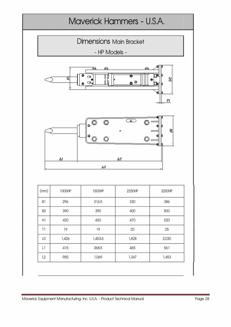
Maverick Hammers - U.S.A.
Dimensions Main Bracket
- HP Models -
(mm) 1000HP 1500HP 2250HP 3250HP
B1 296 316.5 330 386
B2 390 390 400 500
H1 420 420 470 520
T1 19 19 20 25
L0 1,426 1,453.5 1,828 2,030
L1 415 368.5 465 561
L2 955 1,069 1,347 1,453
Maverick Equipment Manufacturing, Inc. U.S.A. - Product Technical Manual Page 29
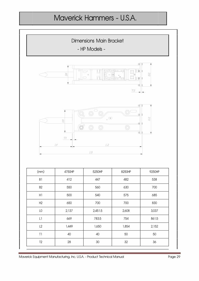
Maverick Hammers - U.S.A.
Dimensions Main Bracket
- HP Models -
(mm) 4750HP 5250HP 8250HP 9250HP
B1 412 447 482 538
B2 550 560 630 700
H1 500 540 575 685
H2 650 700 700 830
L0 2,137 2,451.5 2,608 3,037
L1 669 783.5 754 861.5
L2 1,449 1,650 1,854 2,152
T1 40 40 50 50
T2 28 30 32 36
Maverick Equipment Manufacturing, Inc. U.S.A. - Product Technical Manual Page 30
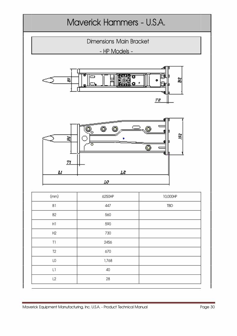
Maverick Hammers - U.S.A.
Dimensions Main Bracket
- HP Models -
(mm) 6250HP 10,000HP
B1 447 TBD
B2 560
H1 590
H2 730
T1 2456
T2 670
L0 1,768
L1 40
L2 28
Maverick Equipment Manufacturing, Inc. U.S.A. - Product Technical Manual Page 31
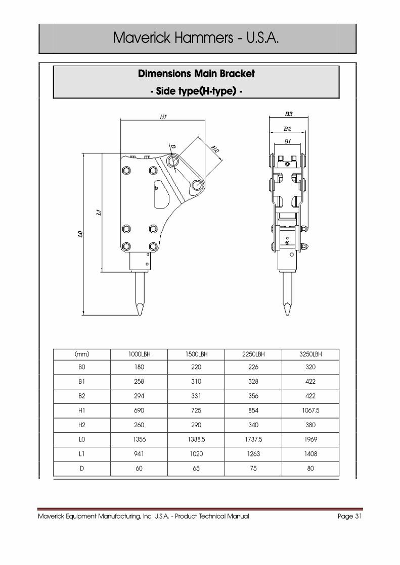
Maverick Hammers - U.S.A.
Dimensions Main Bracket
- Side type(H-type) -
(mm) 1000LBH 1500LBH 2250LBH 3250LBH
B0 180 220 226 320
B1 258 310 328 422
B2 294 331 356 422
H1 690 725 854 1067.5
H2 260 290 340 380
L0 1356 1388.5 1737.5 1969
L1 941 1020 1263 1408
D 60 65 75 80
Maverick Equipment Manufacturing, Inc. U.S.A. - Product Technical Manual Page 32
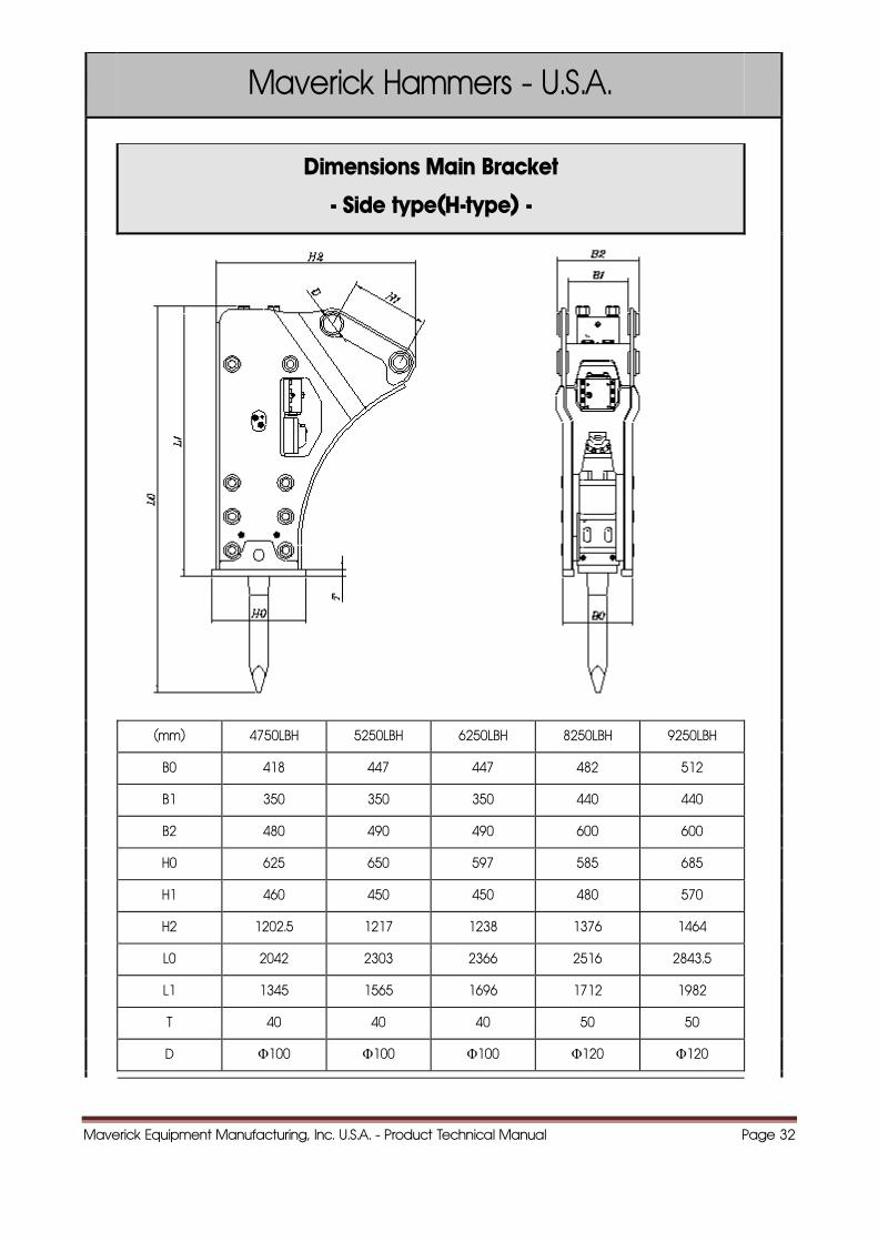
Maverick Hammers - U.S.A.
Dimensions Main Bracket
- Side type(H-type) -
(mm) 4750LBH 5250LBH 6250LBH 8250LBH 9250LBH
B0 418 447 447 482 512
B1 350 350 350 440 440
B2 480 490 490 600 600
H0 625 650 597 585 685
H1 460 450 450 480 570
H2 1202.5 1217 1238 1376 1464
L0 2042 2303 2366 2516 2843.5
L1 1345 1565 1696 1712 1982
T 40 40 40 50 50
D Φ100 Φ100 Φ100 Φ120 Φ120
Maverick Equipment Manufacturing, Inc. U.S.A. - Product Technical Manual Page 33
Maverick Hammers - U.S.A.
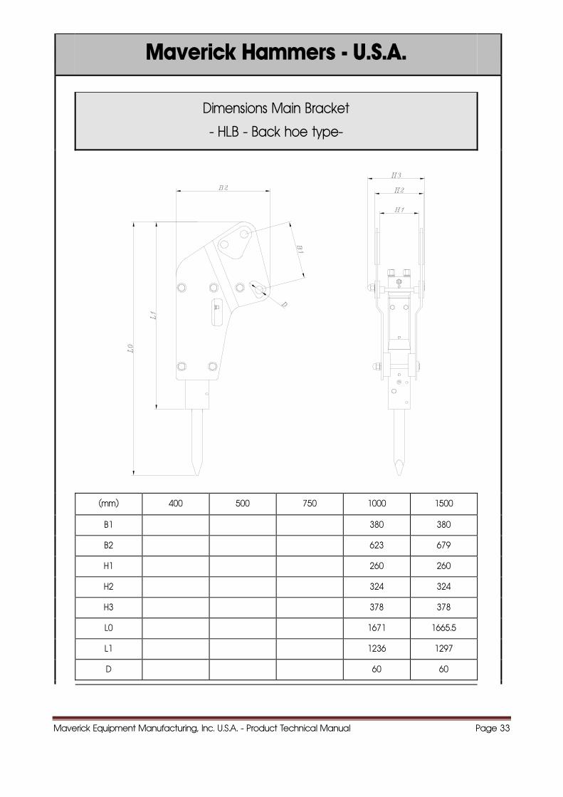
Dimensions Main Bracket
- HLB - Back hoe type-
(mm) 400 500 750 1000 1500
B1 380 380
B2 623 679
H1 260 260
H2 324 324
H3 378 378
L0 1671 1665.5
L1 1236 1297
D 60 60
Maverick Equipment Manufacturing, Inc. U.S.A. - Product Technical Manual Page 34
Maverick Hammers - U.S.A.
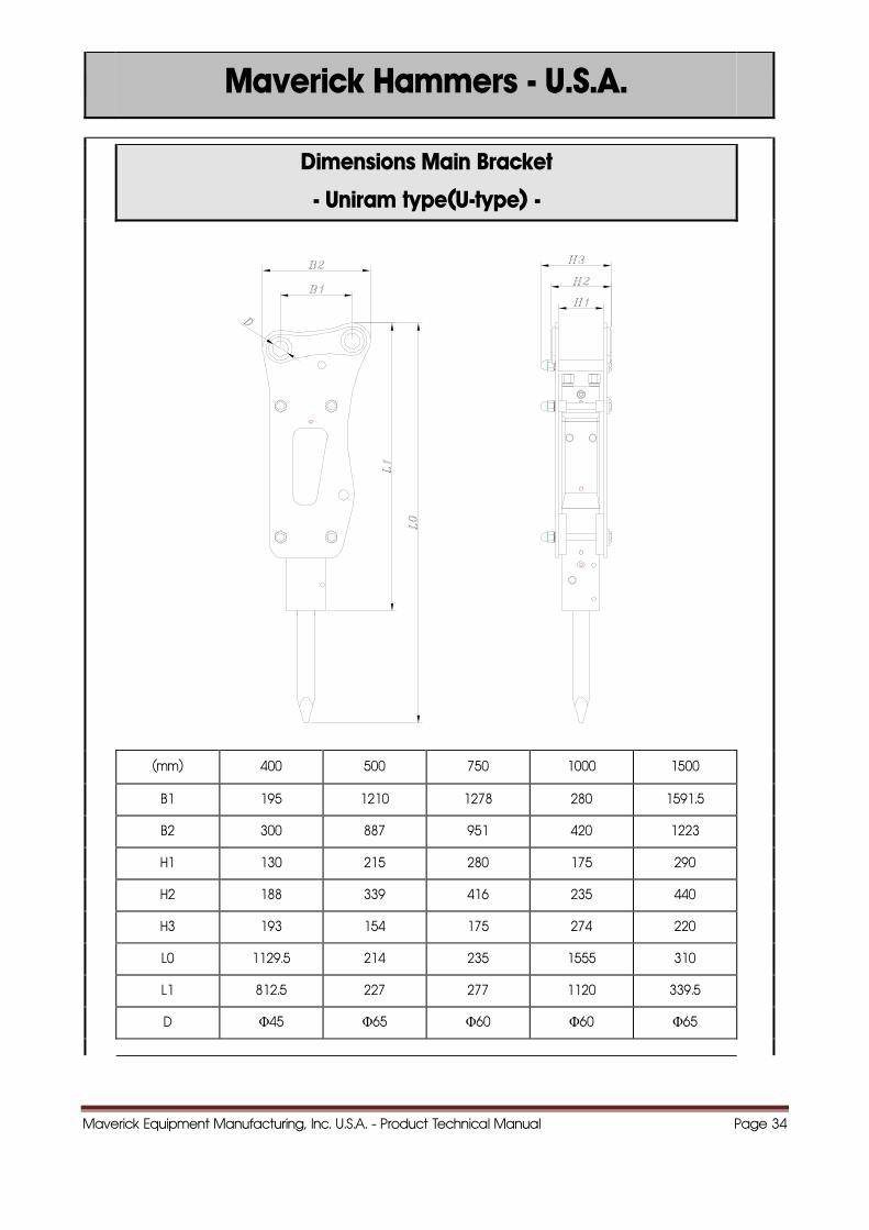
Dimensions Main Bracket
- Uniram type(U-type) -
(mm) 400 500 750 1000 1500
B1 195 1210 1278 280 1591.5
B2 300 887 951 420 1223
H1 130 215 280 175 290
H2 188 339 416 235 440
H3 193 154 175 274 220
L0 1129.5 214 235 1555 310
L1 812.5 227 277 1120 339.5
D Φ45 Φ65 Φ60 Φ60 Φ65
Maverick Equipment Manufacturing, Inc. U.S.A. - Product Technical Manual Page 35
Maverick Hammers - U.S.A.
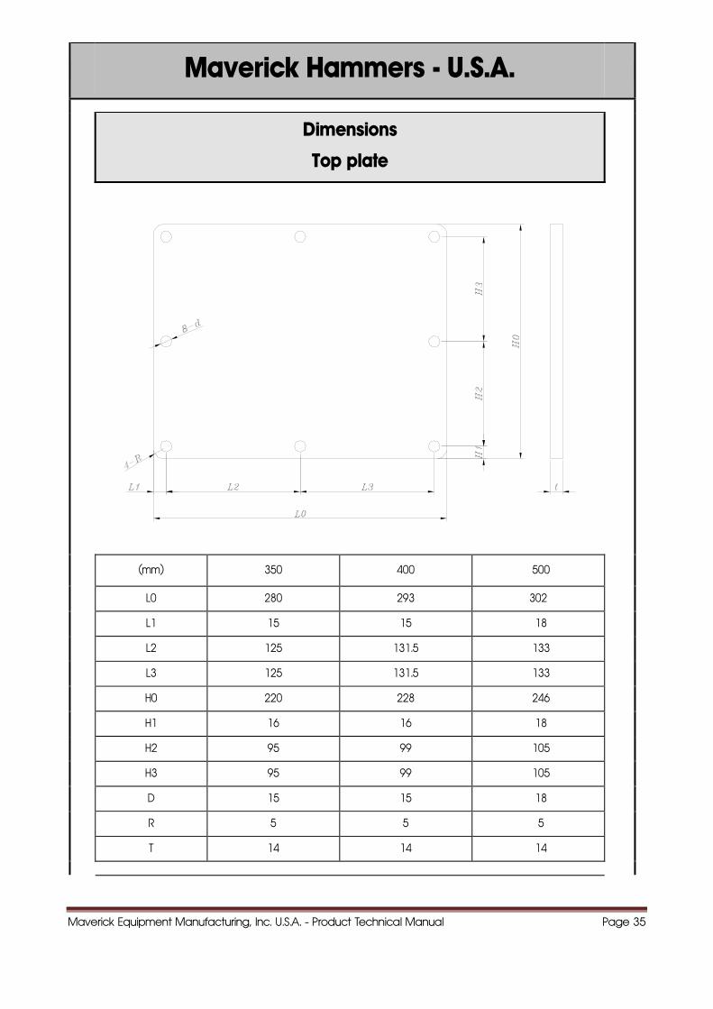
Dimensions
Top plate
(mm) 350 400 500
L0 280 293 302
L1 15 15 18
L2 125 131.5 133
L3 125 131.5 133
H0 220 228 246
H1 16 16 18
H2 95 99 105
H3 95 99 105
D 15 15 18
R 5 5 5
T 14 14 14
Maverick Equipment Manufacturing, Inc. U.S.A. - Product Technical Manual Page 36
Maverick Hammers - U.S.A.
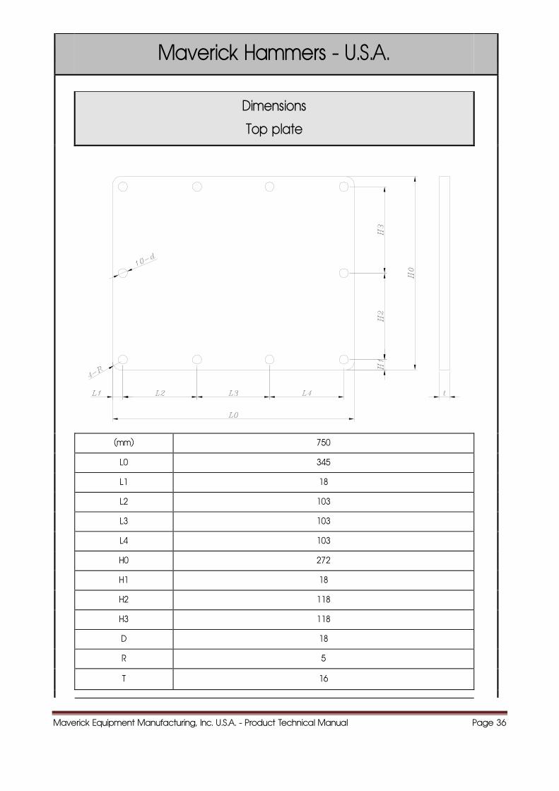
Dimensions
Top plate
(mm) 750
L0 345
L1 18
L2 103
L3 103
L4 103
H0 272
H1 18
H2 118
H3 118
D 18
R 5
T 16
Maverick Equipment Manufacturing, Inc. U.S.A. - Product Technical Manual Page 37
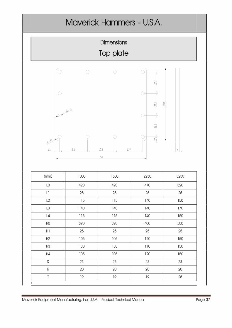
Maverick Hammers - U.S.A.
Dimensions
Top plate
(mm) 1000 1500 2250 3250
L0 420 420 470 520
L1 25 25 25 25
L2 115 115 140 150
L3 140 140 140 170
L4 115 115 140 150
H0 390 390 400 500
H1 25 25 25 25
H2 105 105 120 150
H3 130 130 110 150
H4 105 105 120 150
D 23 23 23 23
R 20 20 20 20
T 19 19 19 25
\
Maverick Equipment Manufacturing, Inc. U.S.A. - Product Technical Manual Page 38
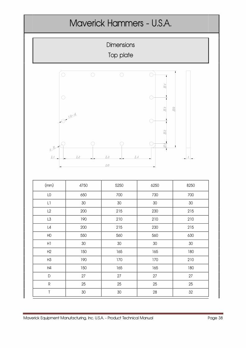
Maverick Hammers - U.S.A.
Dimensions
Top plate
(mm) 4750 5250 6250 8250
L0 650 700 730 700
L1 30 30 30 30
L2 200 215 230 215
L3 190 210 210 210
L4 200 215 230 215
H0 550 560 560 630
H1 30 30 30 30
H2 150 165 165 180
H3 190 170 170 210
H4 150 165 165 180
D 27 27 27 27
R 25 25 25 25
T 30 30 28 32
Maverick Equipment Manufacturing, Inc. U.S.A. - Product Technical Manual Page 39
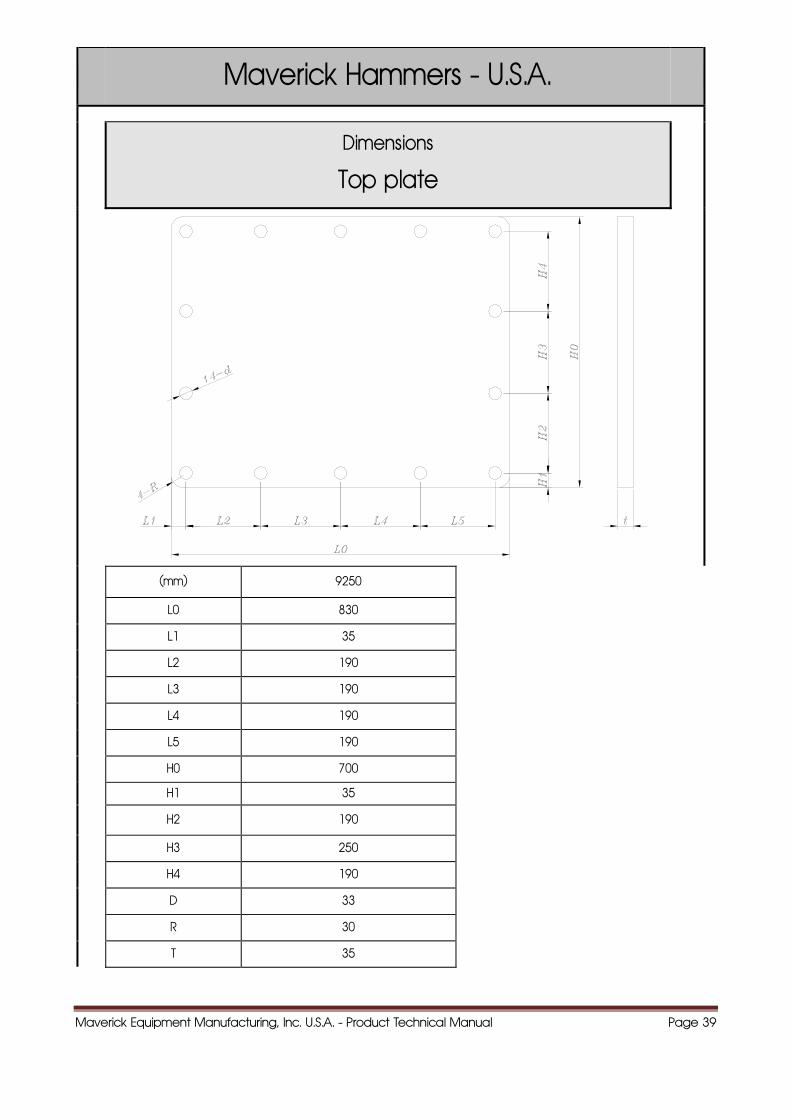
Maverick Hammers - U.S.A.
Dimensions
Top plate
(mm) 9250
L0 830
L1 35
L2 190
L3 190
L4 190
L5 190
H0 700
H1 35
H2 190
H3 250
H4 190
D 33
R 30
T 35
Maverick Equipment Manufacturing, Inc. U.S.A. - Product Technical Manual Page 40
33..SSTTRRUUCCTTUURRAALL VVIIEEWW OOFF TTHHEE HHAAMMMMEERRSS
Maverick Hammers - U.S.A.
Maverick Equipment Manufacturing, Inc. U.S.A. - Product Technical Manual Page 41
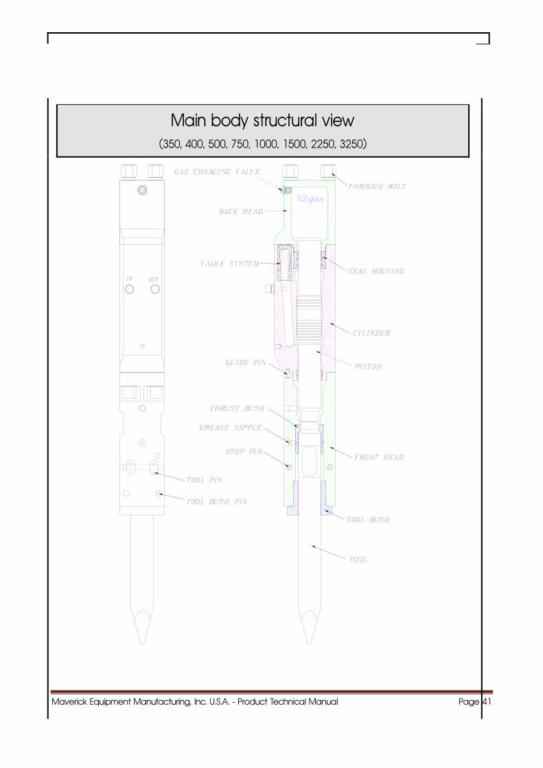
Main body structural view (350, 400, 500, 750, 1000, 1500, 2250, 3250)
Maverick Equipment Manufacturing, Inc. U.S.A. - Product Technical Manual Page 42
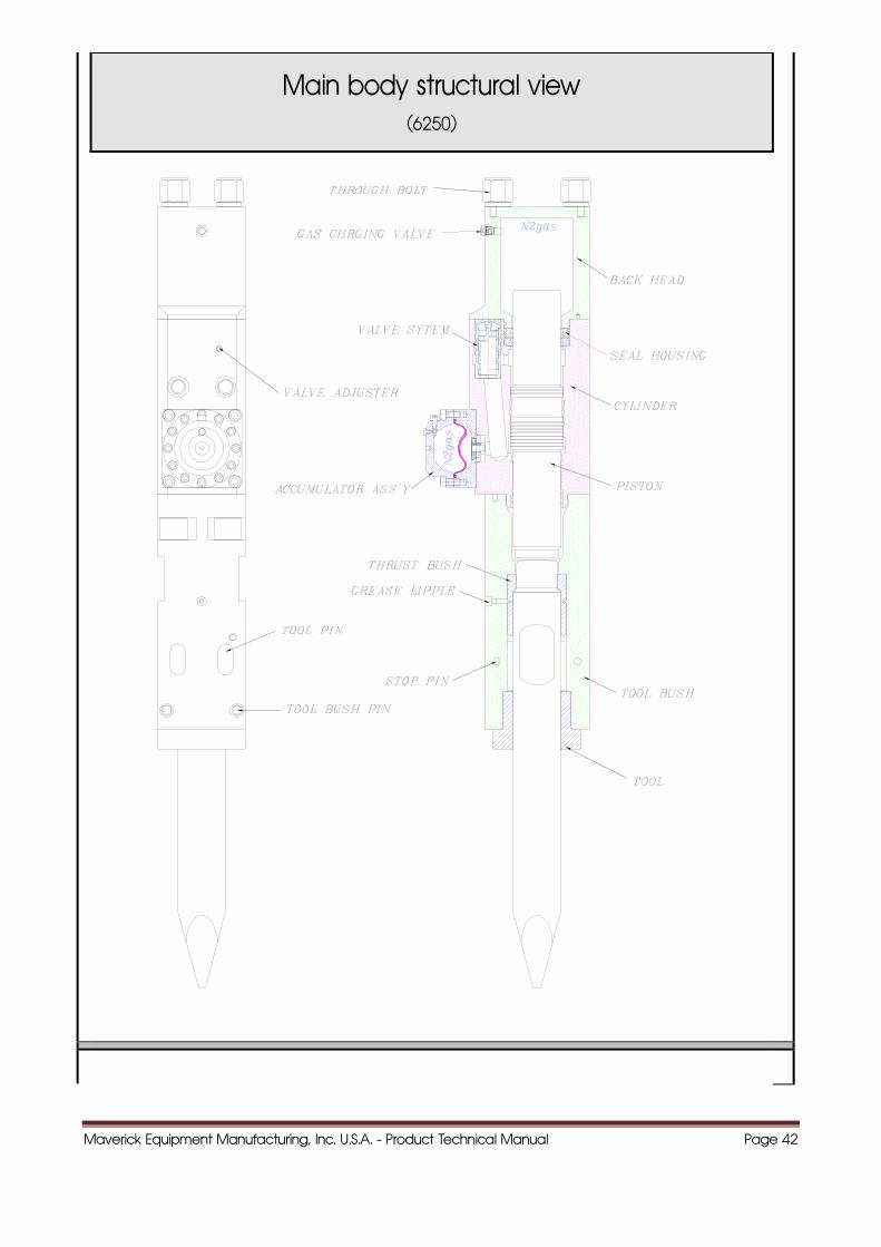
Main body structural view (6250)
Maverick Equipment Manufacturing, Inc. U.S.A. - Product Technical Manual Page 43
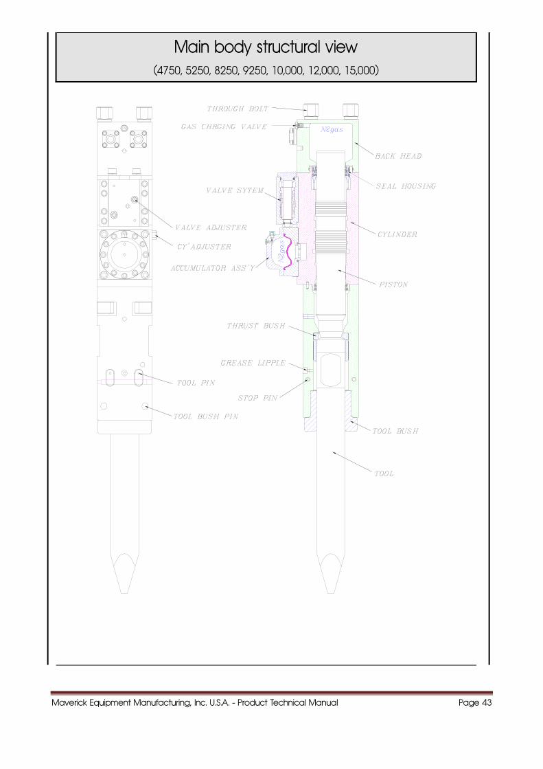
Main body structural view (4750, 5250, 8250, 9250, 10,000, 12,000, 15,000)
Maverick Equipment Manufacturing, Inc. U.S.A. - Product Technical Manual Page 44
Maverick Hammers - U.S.A.
44..FFUUNNCCTTIIOONNSS OOFF TTHHEE MMAAIINN CCOOMMPPOONNEENNTTSS
M i k H U S A
Maverick Equipment Manufacturing, Inc. U.S.A. - Product Technical Manual Page 45
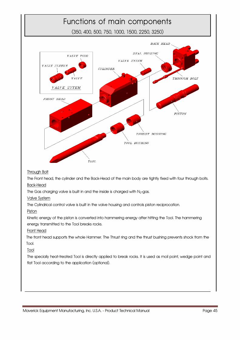
Functions of main components (350, 400, 500, 750, 1000, 1500, 2250, 3250)
Through Bolt
The Front head, the cylinder and the Back-Head of the main body are tightly fixed with four through bolts.
Back-Head
The Gas charging valve is built in and the inside is charged with N2-gas.
Valve System
The Cylindrical control valve is built in the valve housing and controls piston reciprocation.
Piston
Kinetic energy of the piston is converted into hammering energy after hitting the Tool. The hammering
energy transmitted to the Tool breaks rocks.
Front Head
The front head supports the whole Hammer. The Thrust ring and the thrust bushing prevents shock from the
Tool.
Tool
The specially heat-treated Tool is directly applied to break rocks. It is used as moil point, wedge point and
flat Tool according to the application (optional).
Maverick Equipment Manufacturing, Inc. U.S.A. - Product Technical Manual Page 46
Maverick Hammers - U.S.A.
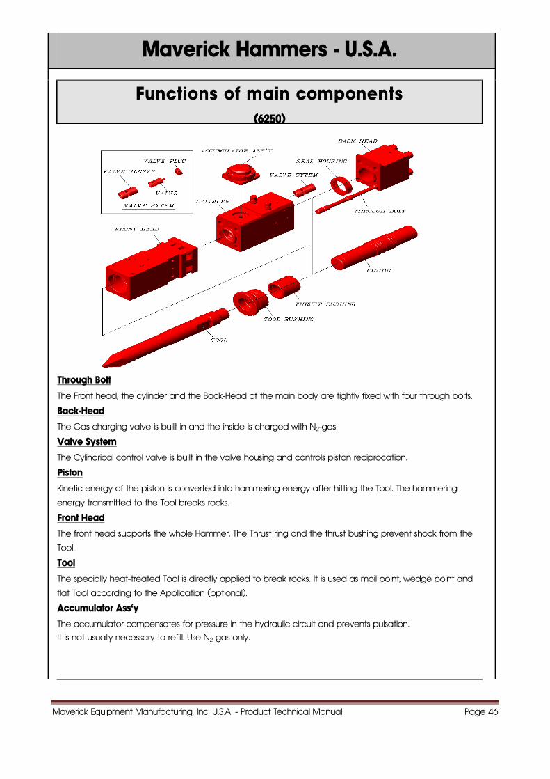
Functions of main components (6250)
Through Bolt
The Front head, the cylinder and the Back-Head of the main body are tightly fixed with four through bolts.
Back-Head
The Gas charging valve is built in and the inside is charged with N2-gas.
Valve System
The Cylindrical control valve is built in the valve housing and controls piston reciprocation.
Piston
Kinetic energy of the piston is converted into hammering energy after hitting the Tool. The hammering
energy transmitted to the Tool breaks rocks.
Front Head
The front head supports the whole Hammer. The Thrust ring and the thrust bushing prevent shock from the
Tool.
Tool
The specially heat-treated Tool is directly applied to break rocks. It is used as moil point, wedge point and
flat Tool according to the Application (optional).
Accumulator Ass'y
The accumulator compensates for pressure in the hydraulic circuit and prevents pulsation.
It is not usually necessary to refill. Use N2-gas only.
Maverick Equipment Manufacturing, Inc. U.S.A. - Product Technical Manual Page 47
Maverick Hammers - U.S.A.
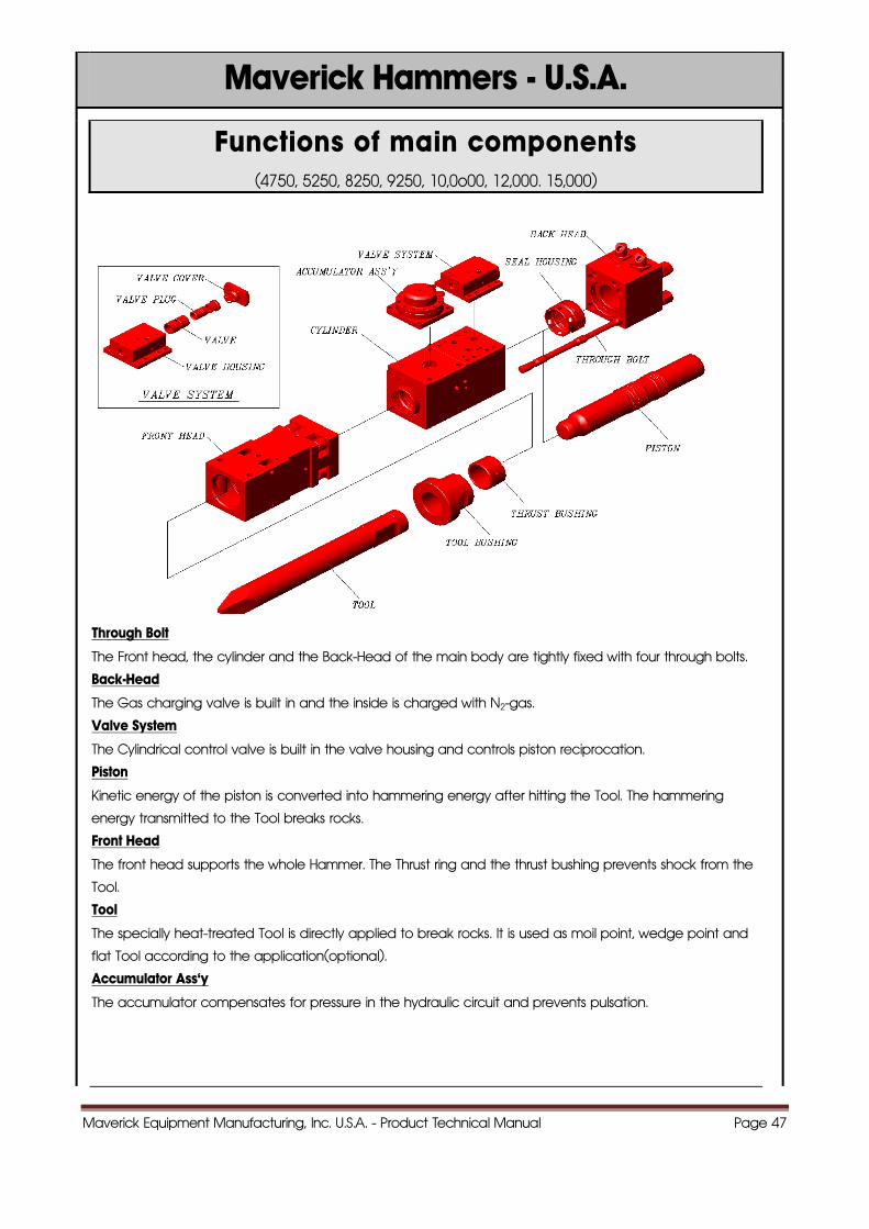
Functions of main components (4750, 5250, 8250, 9250, 10,0o00, 12,000. 15,000)
Through Bolt
The Front head, the cylinder and the Back-Head of the main body are tightly fixed with four through bolts.
Back-Head
The Gas charging valve is built in and the inside is charged with N2-gas.
Valve System
The Cylindrical control valve is built in the valve housing and controls piston reciprocation.
Piston
Kinetic energy of the piston is converted into hammering energy after hitting the Tool. The hammering
energy transmitted to the Tool breaks rocks.
Front Head
The front head supports the whole Hammer. The Thrust ring and the thrust bushing prevents shock from the
Tool.
Tool
The specially heat-treated Tool is directly applied to break rocks. It is used as moil point, wedge point and
flat Tool according to the application(optional).
Accumulator Ass'y
The accumulator compensates for pressure in the hydraulic circuit and prevents pulsation.
Maverick Equipment Manufacturing, Inc. U.S.A. - Product Technical Manual Page 48
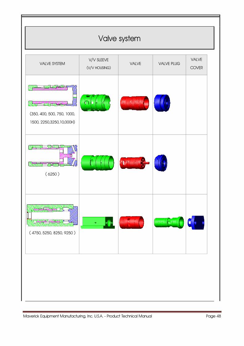
Valve system
VALVE SYSTEM V/V SLEEVE
(V/V HOUSING) VALVE VALVE PLUG
VALVE
COVER
(350, 400, 500, 750, 1000,
1500, 2250,3250,10,000H)
( 6250 )
( 4750, 5250, 8250, 9250 )
Maverick Equipment Manufacturing, Inc. U.S.A. - Product Technical Manual Page 49
Maverick Hammers - U.S.A.
55..PPRRIINNCCIIPPLLEE OOFF OOPPEERRAATTIIOONN
Maverick Hammers - U.S.A.
Maverick Equipment Manufacturing, Inc. U.S.A. - Product Technical Manual Page 50
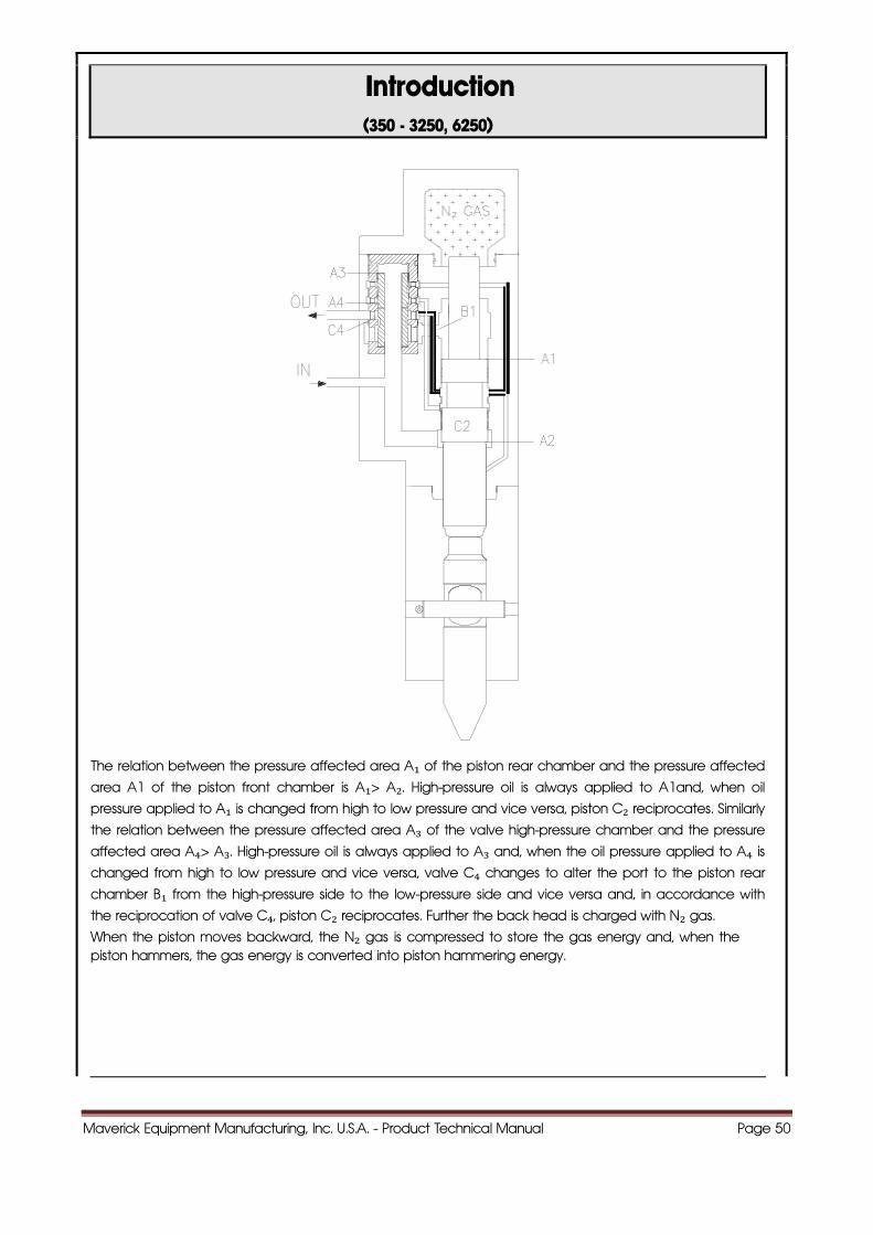
Introduction (350 - 3250, 6250)
The relation between the pressure affected area A₁ of the piston rear chamber and the pressure affected
area A1 of the piston front chamber is A₁> A₂. High-pressure oil is always applied to A1and, when oil
pressure applied to A₁ is changed from high to low pressure and vice versa, piston C₂ reciprocates. Similarly
the relation between the pressure affected area A₃ of the valve high-pressure chamber and the pressure
affected area A₄> A₃. High-pressure oil is always applied to A₃ and, when the oil pressure applied to A₄ is changed from high to low pressure and vice versa, valve C₄ changes to alter the port to the piston rear
chamber B₁ from the high-pressure side to the low-pressure side and vice versa and, in accordance with
the reciprocation of valve C₄, piston C₂ reciprocates. Further the back head is charged with N₂ gas.
When the piston moves backward, the N₂ gas is compressed to store the gas energy and, when the piston hammers, the gas energy is converted into piston hammering energy.
Maverick Equipment Manufacturing, Inc. U.S.A. - Product Technical Manual Page 51
Maverick Hammers - U.S.A.
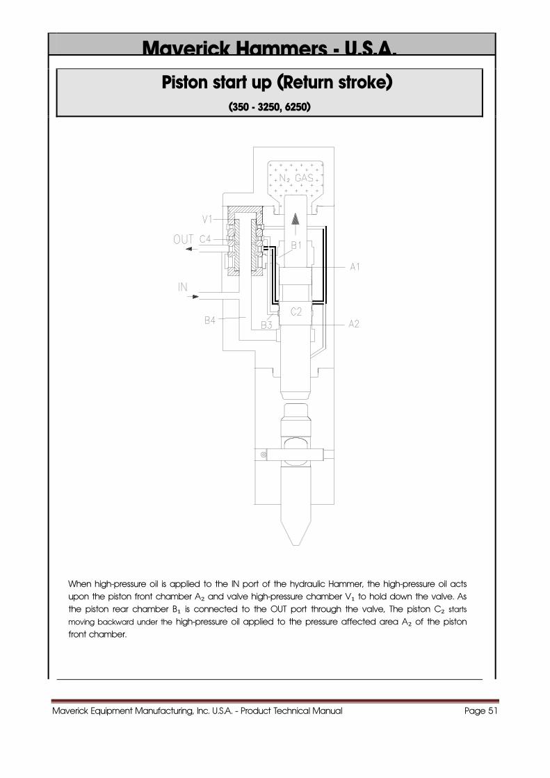
Piston start up (Return stroke) (350 - 3250, 6250)
When high-pressure oil is applied to the IN port of the hydraulic Hammer, the high-pressure oil acts upon the piston front chamber A₂ and valve high-pressure chamber V₁ to hold down the valve. As the piston rear chamber B₁ is connected to the OUT port through the valve, The piston C₂ starts
moving backward under the high-pressure oil applied to the pressure affected area A₂ of the piston front chamber.
Maverick Equipment Manufacturing, Inc. U.S.A. - Product Technical Manual Page 52
Maverick Hammers - U.S.A.
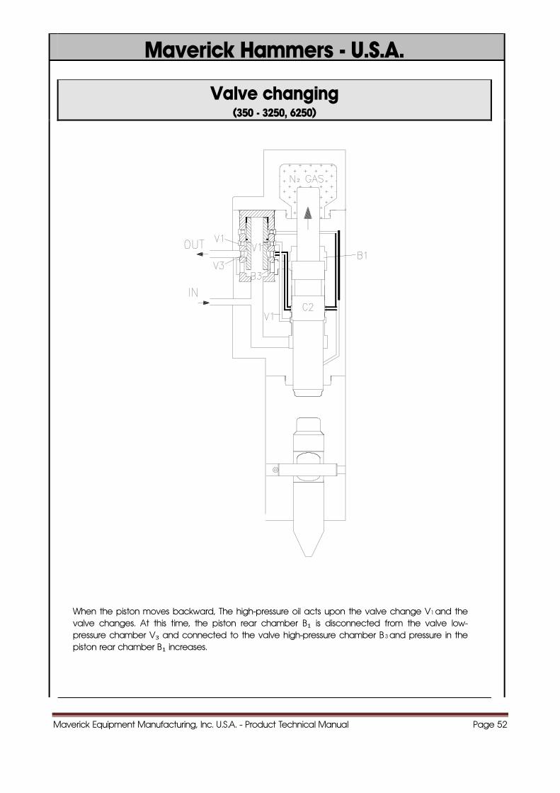
Valve changing (350 - 3250, 6250)
When the piston moves backward, The high-pressure oil acts upon the valve change V1 and the valve changes. At this time, the piston rear chamber B₁ is disconnected from the valve low-pressure chamber V₃ and connected to the valve high-pressure chamber B 3 and pressure in the piston rear chamber B₁ increases.
Maverick Equipment Manufacturing, Inc. U.S.A. - Product Technical Manual Page 53
Maverick Hammers - U.S.A.
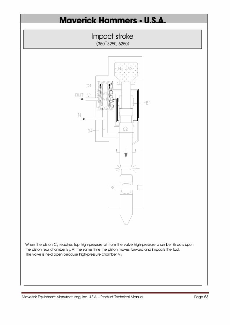
Impact stroke (350 ~ 3250, 6250)
When the piston C₂ reaches top high-pressure oil from the valve high-pressure chamber B 3 acts upon the piston rear chamber B₁. At the same time the piston moves forward and impacts the tool. The valve is held open because high-pressure chamber V₁
Maverick Equipment Manufacturing, Inc. U.S.A. - Product Technical Manual Page 54
Maverick Hammers - U.S.A.
Introduction
(4750, 5250, 8250, 9250, 10,000, 12,000, 15,000)
Maverick Equipment Manufacturing, Inc. U.S.A. - Product Technical Manual Page 55
Maverick Hammers - U.S.A.
Introduction
(4750, 5250, 8250, 9250, 10,000, 12,000, 15,000)
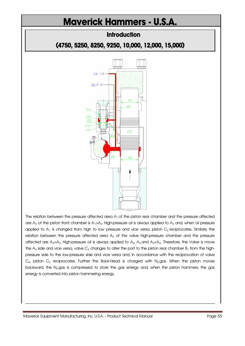
The relation between the pressure affected area A1 of the piston rear chamber and the pressure affected
are A2 of the piston front chamber is A1>A2. High-pressure oil is always applied to A2 and, when oil pressure
applied to A1 is changed from high to low pressure and vice versa, piston C2 reciprocates. Similarly the
relation between the pressure affected area A3 of the valve high-pressure chamber and the pressure
affected are A4>A3. High-pressure oil is always applied to A3, A4 and A3<A4. Therefore, the Valve is move
the A4 side and vice versa, valve C4 changes to alter the port to the piston rear chamber B1 from the high-
pressure side to the low-pressure side and vice versa and, in accordance with the reciprocation of valve
C4, piston C2 reciprocates. Further the Back-Head is charged with N2-gas. When the piston moves
backward, the N2-gas is compressed to store the gas energy and, when the piston hammers, the gas
energy is converted into piston hammering energy.
Maverick Equipment Manufacturing, Inc. U.S.A. - Product Technical Manual Page 56
Maverick Hammers - U.S.A.
Piston start up (Return stroke)
(4750, 5250, 8250, 9250, 10,000, 12,000, 15,000)
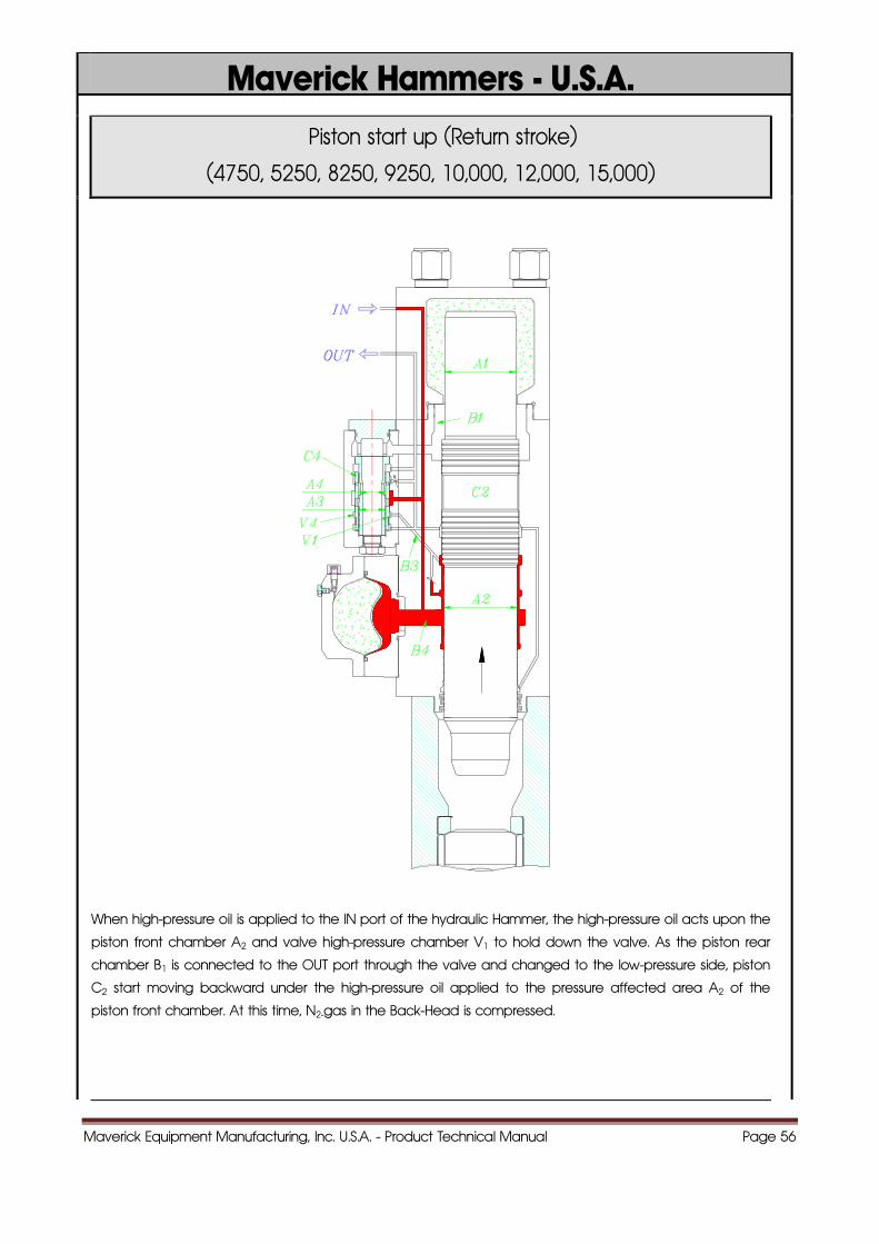
When high-pressure oil is applied to the IN port of the hydraulic Hammer, the high-pressure oil acts upon the
piston front chamber A2 and valve high-pressure chamber V1 to hold down the valve. As the piston rear
chamber B1 is connected to the OUT port through the valve and changed to the low-pressure side, piston
C2 start moving backward under the high-pressure oil applied to the pressure affected area A2 of the
piston front chamber. At this time, N2-gas in the Back-Head is compressed.
Maverick Equipment Manufacturing, Inc. U.S.A. - Product Technical Manual Page 57
Maverick Hammers - U.S.A.
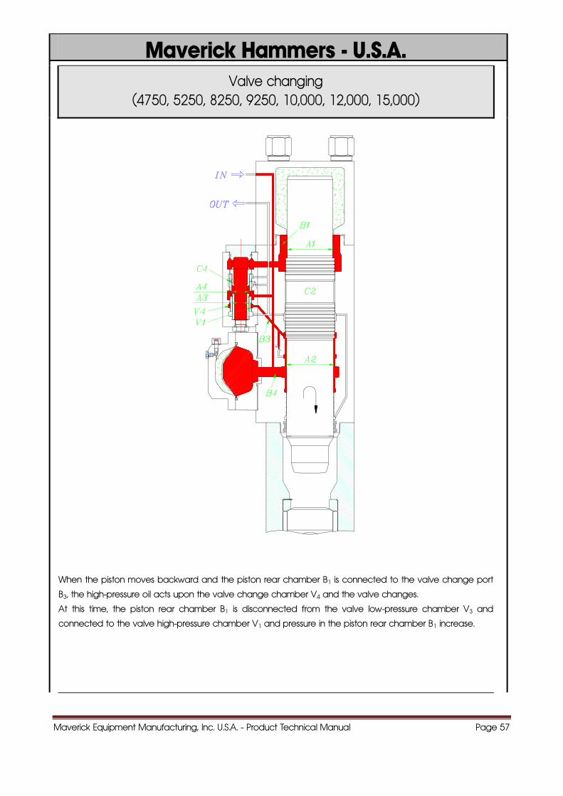
Valve changing (4750, 5250, 8250, 9250, 10,000, 12,000, 15,000)
When the piston moves backward and the piston rear chamber B1 is connected to the valve change port
B3, the high-pressure oil acts upon the valve change chamber V4 and the valve changes.
At this time, the piston rear chamber B1 is disconnected from the valve low-pressure chamber V3 and
connected to the valve high-pressure chamber V1 and pressure in the piston rear chamber B1 increase.
Maverick Equipment Manufacturing, Inc. U.S.A. - Product Technical Manual Page 58
Maverick Hammers - U.S.A.
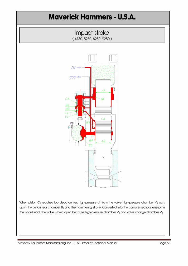
Impact stroke ( 4750, 5250, 8250, 9250 )
When piston C2 reaches top dead center, high-pressure oil from the valve high-pressure chamber V1 acts
upon the piston rear chamber B1 and the hammering stroke. Converted into the compressed gas energy in
the Back-Head. The valve is held open because high-pressure chamber V1 and valve change chamber V4.
Maverick Equipment Manufacturing, Inc. U.S.A. - Product Technical Manual Page 59
66..DDIISSAASSSSEEMMBBLLyy
aanndd AASSSSEEMMBBLLyy
OOFF TTHHEE HHAAMMMMEERR
Maverick Hammers - U.S.A.
Maverick Equipment Manufacturing, Inc. U.S.A. - Product Technical Manual Page 60
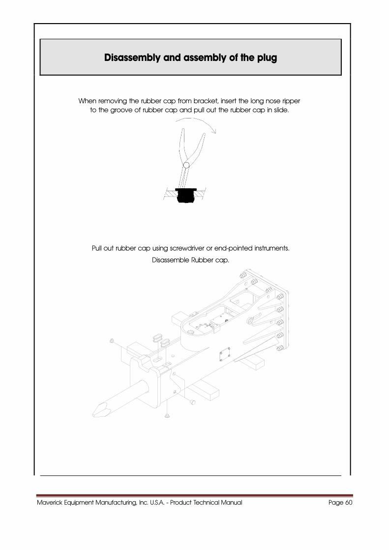
Disassembly and assembly of the plug
When removing the rubber cap from bracket, insert the long nose ripper to the groove of rubber cap and pull out the rubber cap in slide.
Pull out rubber cap using screwdriver or end-pointed instruments.
Disassemble Rubber cap.
Maverick Equipment Manufacturing, Inc. U.S.A. - Product Technical Manual Page 61
Maverick Hammers - U.S.A.
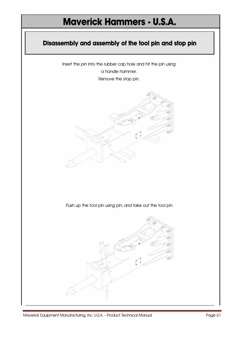
Disassembly and assembly of the tool pin and stop pin
Insert the pin into the rubber cap hole and hit the pin using
a handle hammer.
Remove the stop pin.
Push up the tool pin using pin, and take out the tool pin.
Maverick Equipment Manufacturing, Inc. U.S.A. - Product Technical Manual Page 62
Maverick Hammers - U.S.A.
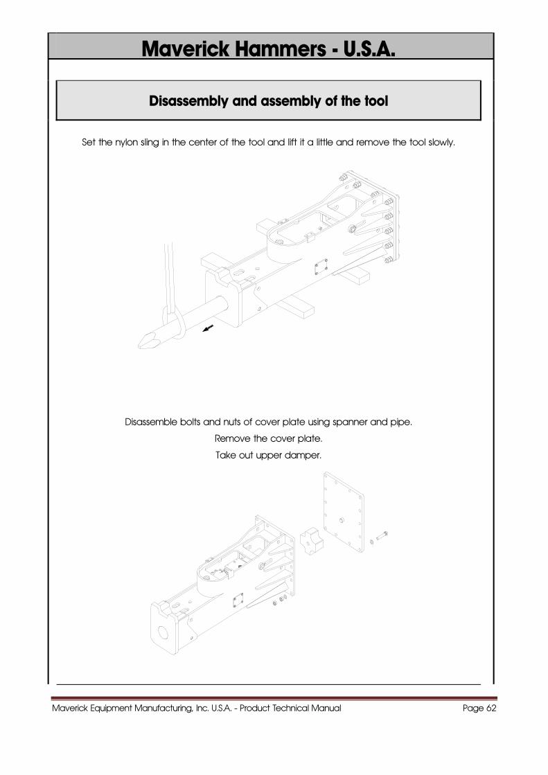
Disassembly and assembly of the tool
Set the nylon sling in the center of the tool and lift it a little and remove the tool slowly.
Disassemble bolts and nuts of cover plate using spanner and pipe.
Remove the cover plate.
Take out upper damper.
Maverick Equipment Manufacturing, Inc. U.S.A. - Product Technical Manual Page 63
Maverick Hammers - U.S.A.
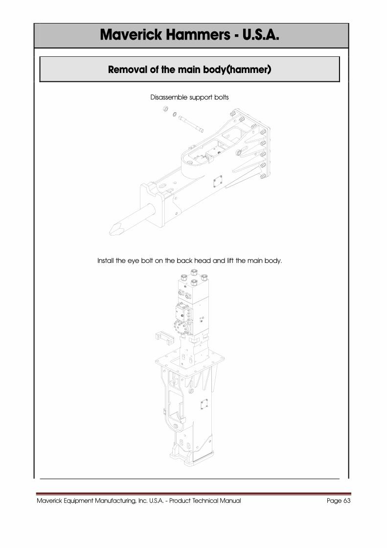
Removal of the main body(hammer)
Disassemble support bolts
Install the eye bolt on the back head and lift the main body.
Maverick Equipment Manufacturing, Inc. U.S.A. - Product Technical Manual Page 64
Maverick Hammers - U.S.A.
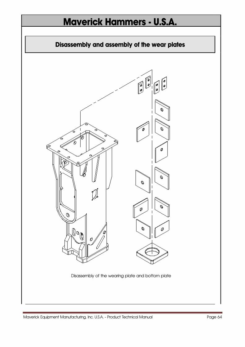
Disassembly and assembly of the wear plates
Disassembly of the wearing plate and bottom plate
Maverick Equipment Manufacturing, Inc. U.S.A. - Product Technical Manual Page 65
Maverick Hammers - U.S.A.
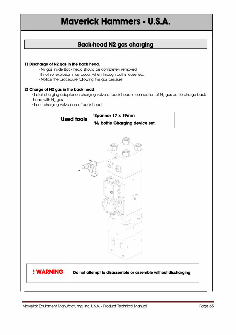
Back-head N2 gas charging
1) Discharge of N2 gas in the back head. · N₂ gas inside Back head should be completely removed.
If not so, explosion may occur, when through bolt is loosened. · Notice the procedure following the gas pressure.
2) Charge of N2 gas in the back head · Install charging adapter on charging valve of back head in connection of N₂ gas bottle charge back
head with N₂ gas. · Insert charging valve cap of back head.
Used tools *Spanner 17 x 19mm
*N₂ bottle Charging device set.
! WARNING Do not attempt to disassemble or assemble without discharging
Maverick Equipment Manufacturing, Inc. U.S.A. - Product Technical Manual Page 66
Maverick Hammers - U.S.A.
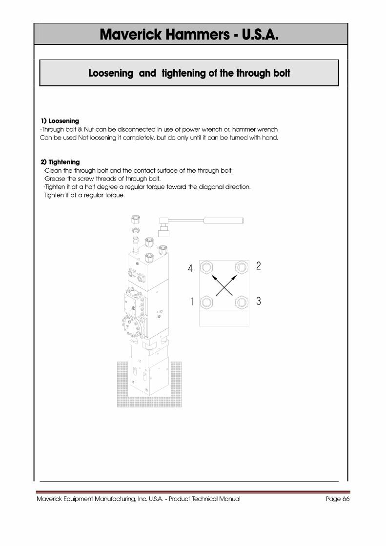
Loosening and tightening of the through bolt
1) Loosening ·Through bolt & Nut can be disconnected in use of power wrench or, hammer wrench Can be used Not loosening it completely, but do only until it can be turned with hand. 2) Tightening ·Clean the through bolt and the contact surface of the through bolt. ·Grease the screw threads of through bolt. ·Tighten it at a half degree a regular torque toward the diagonal direction. Tighten it at a regular torque.
Maverick Equipment Manufacturing, Inc. U.S.A. - Product Technical Manual Page 67
Maverick Hammers - U.S.A.
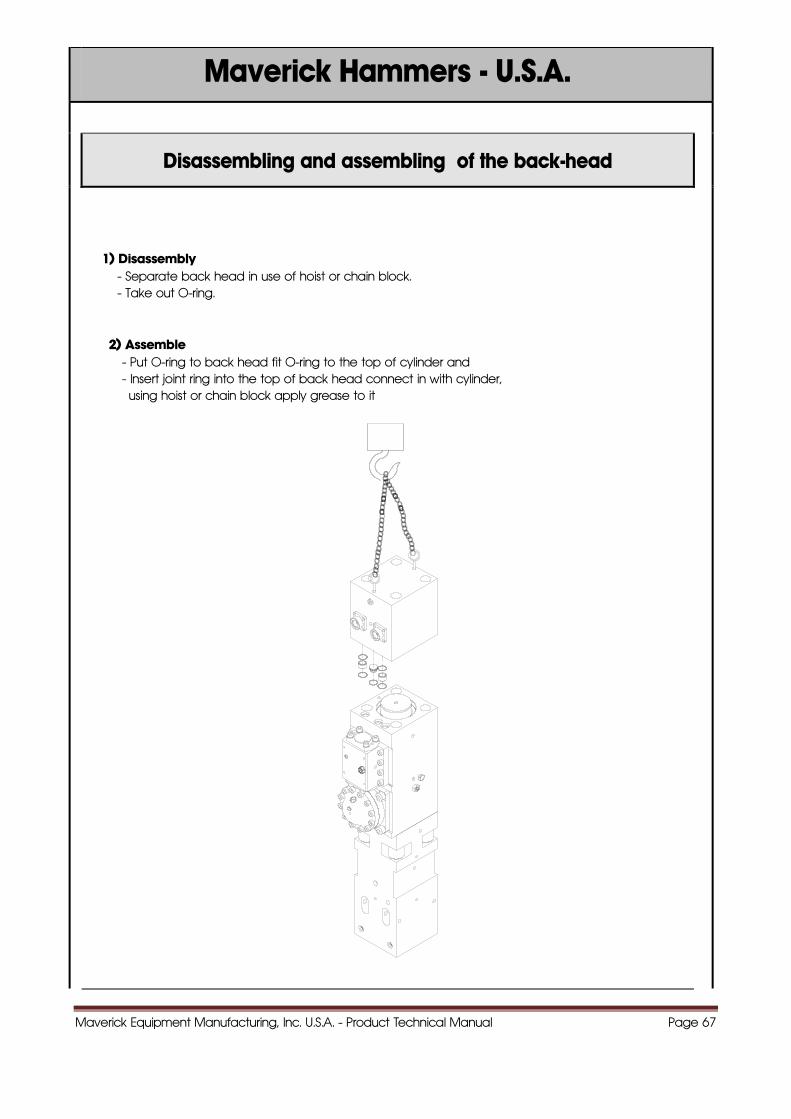
Disassembling and assembling of the back-head
1) Disassembly - Separate back head in use of hoist or chain block. - Take out O-ring.
2) Assemble - Put O-ring to back head fit O-ring to the top of cylinder and - Insert joint ring into the top of back head connect in with cylinder, using hoist or chain block apply grease to it
Maverick Equipment Manufacturing, Inc. U.S.A. - Product Technical Manual Page 68
Maverick Hammers - U.S.A.
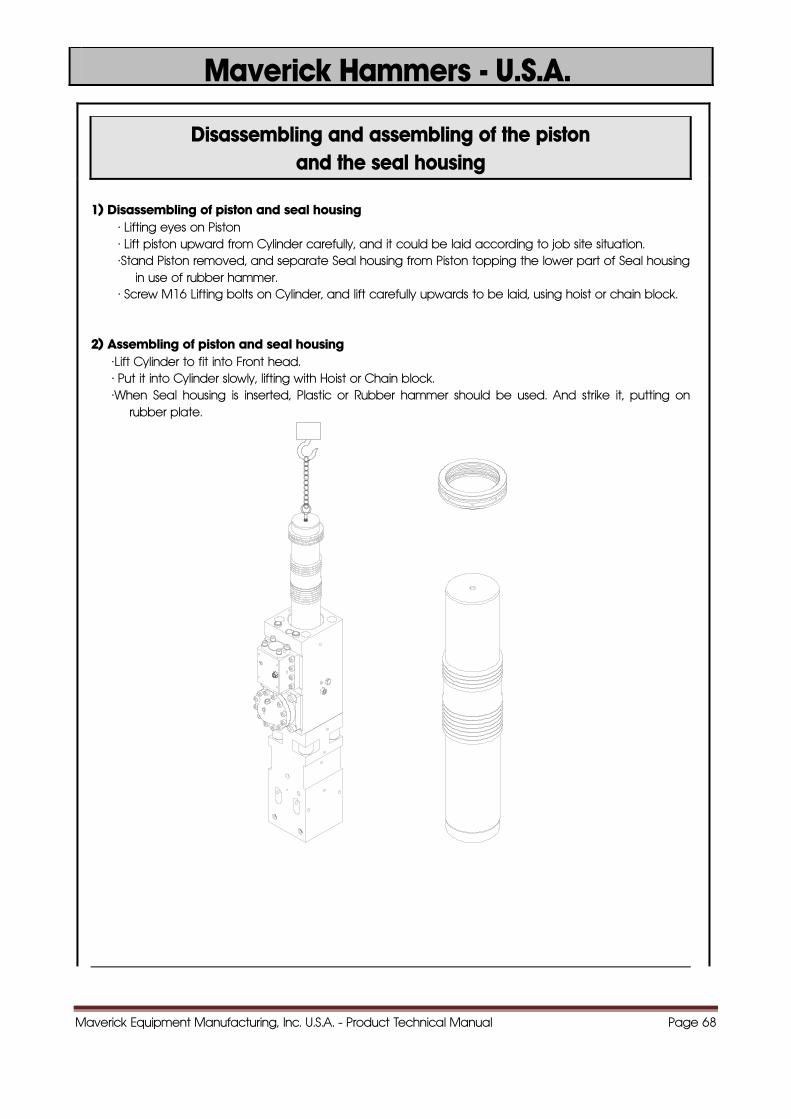
Disassembling and assembling of the piston and the seal housing
1) Disassembling of piston and seal housing · Lifting eyes on Piston · Lift piston upward from Cylinder carefully, and it could be laid according to job site situation. ·Stand Piston removed, and separate Seal housing from Piston topping the lower part of Seal housing
in use of rubber hammer. · Screw M16 Lifting bolts on Cylinder, and lift carefully upwards to be laid, using hoist or chain block.
2) Assembling of piston and seal housing ·Lift Cylinder to fit into Front head. · Put it into Cylinder slowly, lifting with Hoist or Chain block. ·When Seal housing is inserted, Plastic or Rubber hammer should be used. And strike it, putting on
rubber plate.
Maverick Equipment Manufacturing, Inc. U.S.A. - Product Technical Manual Page 69
Maverick Hammers - U.S.A.
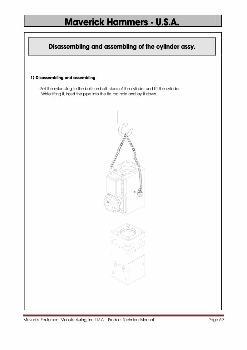
Disassembling and assembling of the cylinder assy.
1) Disassembling and assembling
- Set the nylon sling to the bolts on both sides of the cylinder and lift the cylinder. While lifting it, insert the pipe into the tie rod hole and lay it down.
Maverick Equipment Manufacturing, Inc. U.S.A. - Product Technical Manual Page 70
Maverick Hammers - U.S.A.
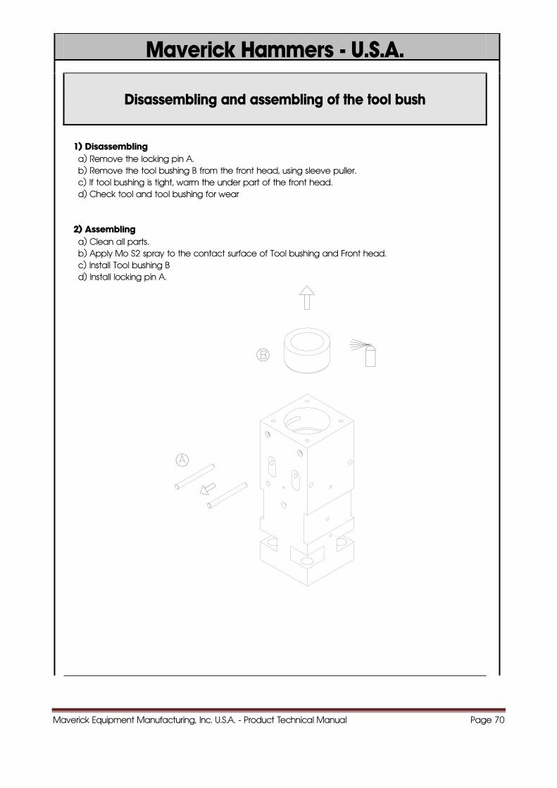
Disassembling and assembling of the tool bush
1) Disassembling a) Remove the locking pin A. b) Remove the tool bushing B from the front head, using sleeve puller. c) If tool bushing is tight, warm the under part of the front head. d) Check tool and tool bushing for wear 2) Assembling a) Clean all parts. b) Apply Mo S2 spray to the contact surface of Tool bushing and Front head. c) Install Tool bushing B d) Install locking pin A.
Maverick Equipment Manufacturing, Inc. U.S.A. - Product Technical Manual Page 71
Maverick Hammers - U.S.A.
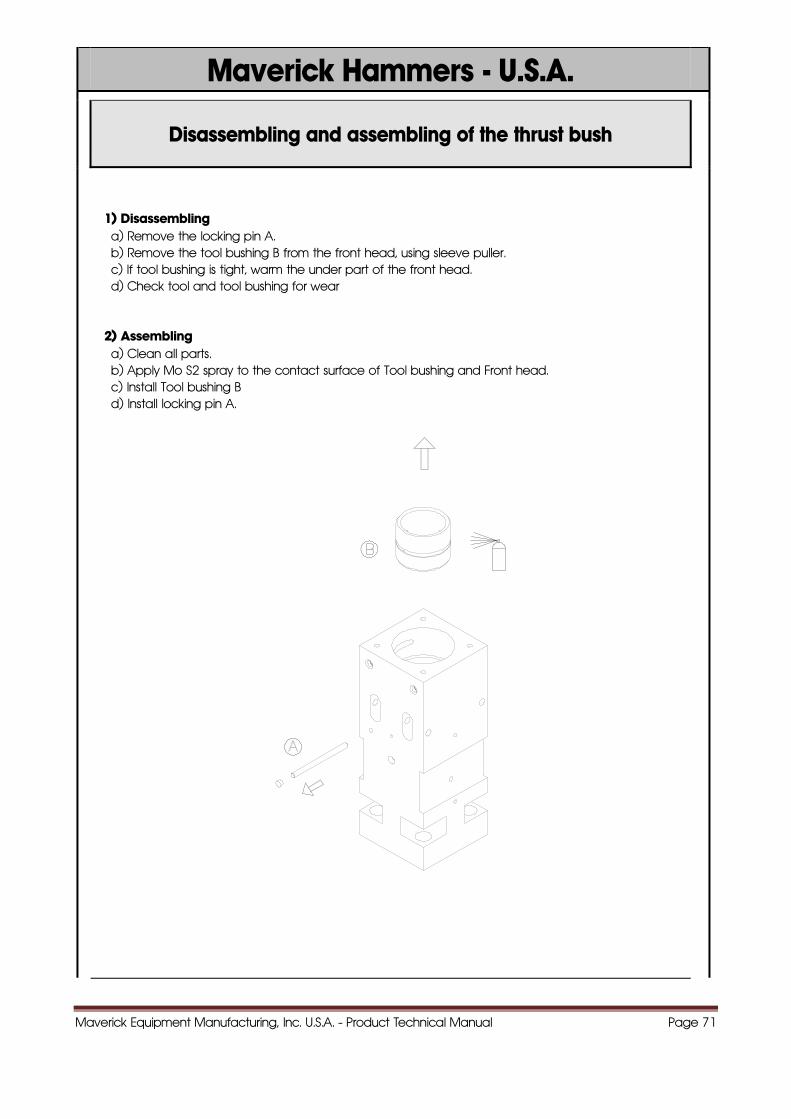
Disassembling and assembling of the thrust bush
1) Disassembling a) Remove the locking pin A. b) Remove the tool bushing B from the front head, using sleeve puller. c) If tool bushing is tight, warm the under part of the front head. d) Check tool and tool bushing for wear 2) Assembling a) Clean all parts. b) Apply Mo S2 spray to the contact surface of Tool bushing and Front head. c) Install Tool bushing B d) Install locking pin A.
Maverick Equipment Manufacturing, Inc. U.S.A. - Product Technical Manual Page 72
Maverick Hammers - U.S.A.
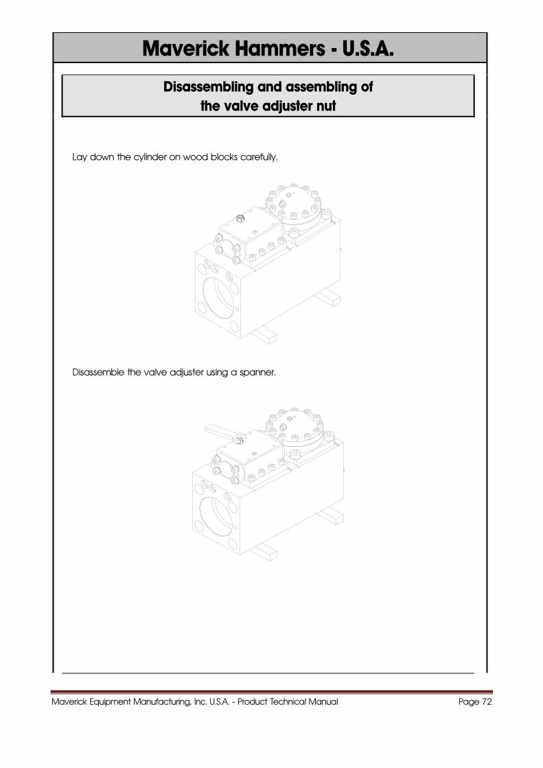
Disassembling and assembling of the valve adjuster nut
Lay down the cylinder on wood blocks carefully.
Disassemble the valve adjuster using a spanner.
Maverick Equipment Manufacturing, Inc. U.S.A. - Product Technical Manual Page 73
Maverick Hammers - U.S.A.
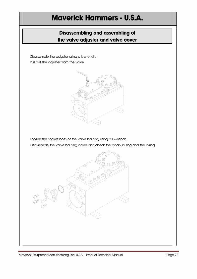
Disassembling and assembling of the valve adjuster and valve cover
Disassemble the adjuster using a L-wrench.
Pull out the adjuster from the valve
Loosen the socket bolts of the valve housing using a L-wrench.
Disassemble the valve housing cover and check the back-up ring and the o-ring.
Maverick Equipment Manufacturing, Inc. U.S.A. - Product Technical Manual Page 74
Maverick Hammers - U.S.A.
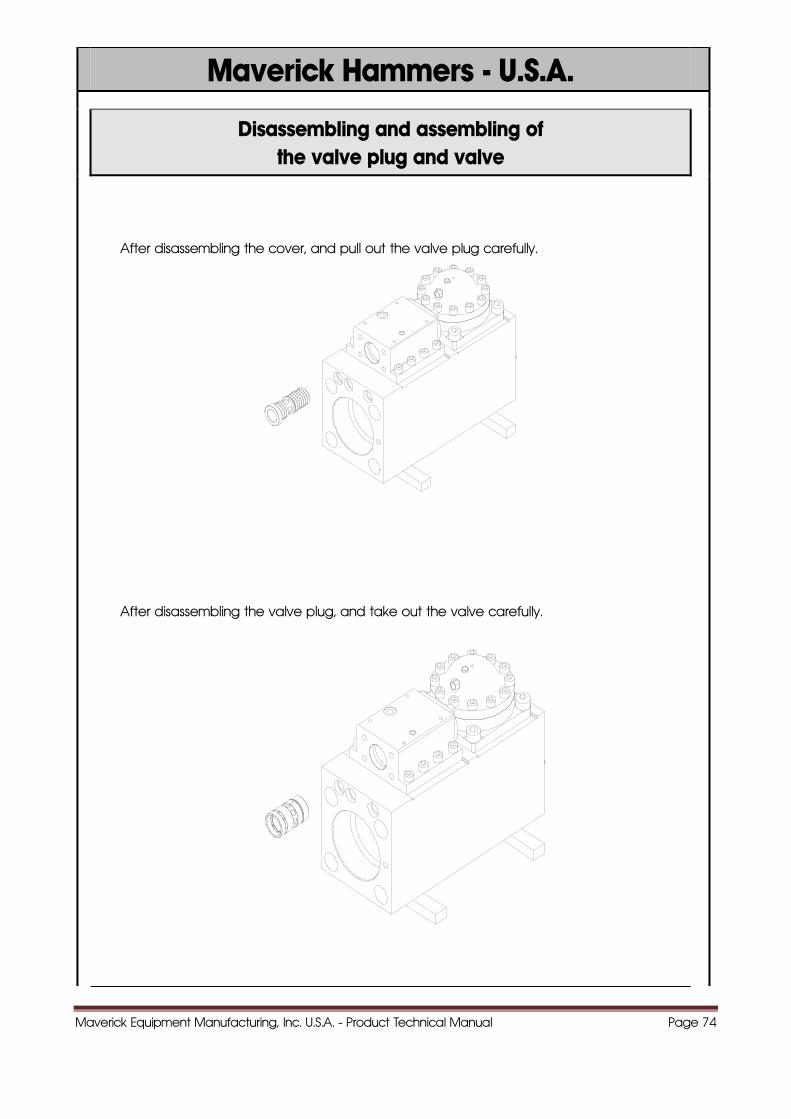
Disassembling and assembling of the valve plug and valve
After disassembling the cover, and pull out the valve plug carefully.
After disassembling the valve plug, and take out the valve carefully.
Maverick Equipment Manufacturing, Inc. U.S.A. - Product Technical Manual Page 75
Maverick Hammers - U.S.A.
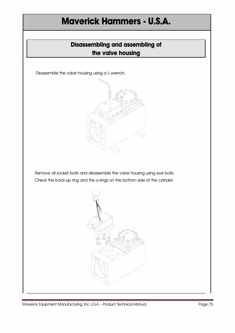
Disassembling and assembling of the valve housing
Disassemble the valve housing using a L-wrench.
Remove all socket bolts and disassemble the valve housing using eye bolts.
Check the back-up ring and the o-rings on the bottom side of the cylinder.
Maverick Equipment Manufacturing, Inc. U.S.A. - Product Technical Manual Page 76
Maverick Hammers - U.S.A.
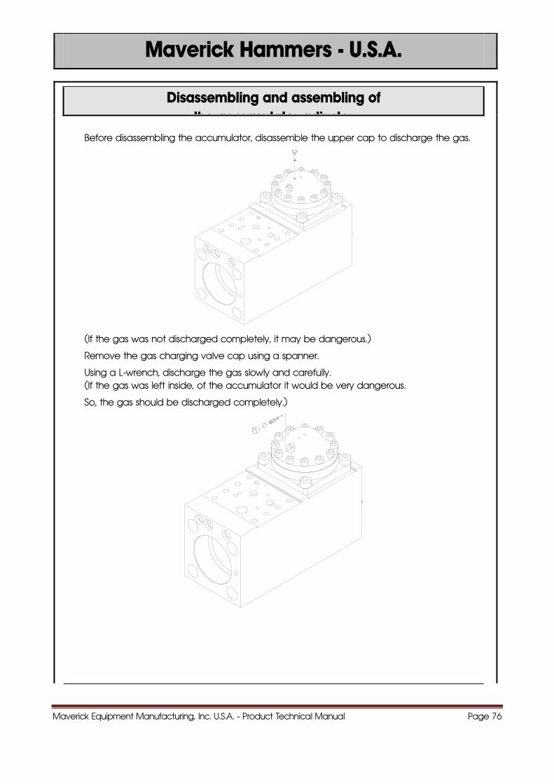
Disassembling and assembling of the accumulator adjuster
Before disassembling the accumulator, disassemble the upper cap to discharge the gas.
(If the gas was not discharged completely, it may be dangerous.)
Remove the gas charging valve cap using a spanner.
Using a L-wrench, discharge the gas slowly and carefully. (If the gas was left inside, of the accumulator it would be very dangerous.
So, the gas should be discharged completely.)
Maverick Equipment Manufacturing, Inc. U.S.A. - Product Technical Manual Page 77
Maverick Hammers - U.S.A.
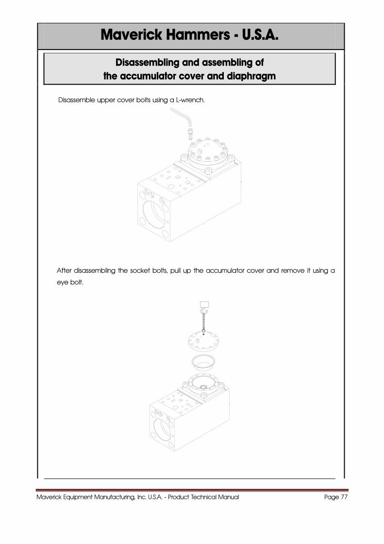
Disassembling and assembling of the accumulator cover and diaphragm
Disassemble upper cover bolts using a L-wrench.
After disassembling the socket bolts, pull up the accumulator cover and remove it using a
eye bolt.
Maverick Equipment Manufacturing, Inc. U.S.A. - Product Technical Manual Page 78
Maverick Hammers - U.S.A.
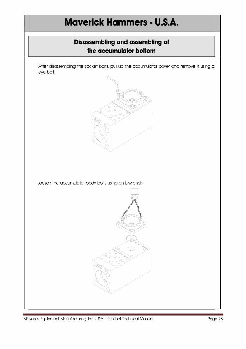
Disassembling and assembling of the accumulator bottom
After disassembling the socket bolts, pull up the accumulator cover and remove it using aeye bolt.
Loosen the accumulator body bolts using an L-wrench.
Maverick Equipment Manufacturing, Inc. U.S.A. - Product Technical Manual Page 79
Maverick Hammers - U.S.A.
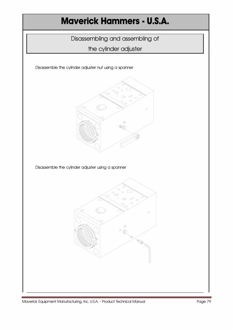
Disassembling and assembling of
the cylinder adjuster
Disassemble the cylinder adjuster nut using a spanner
Disassemble the cylinder adjuster using a spanner
Maverick Equipment Manufacturing, Inc. U.S.A. - Product Technical Manual Page 80
Maverick Hammers - U.S.A.
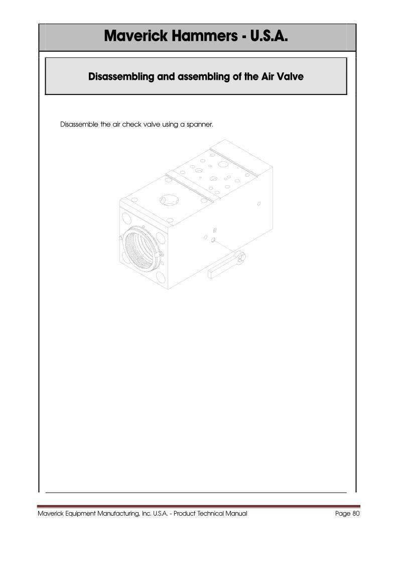
Disassembling and assembling of the Air Valve
Disassemble the air check valve using a spanner.
Maverick Equipment Manufacturing, Inc. U.S.A. - Product Technical Manual Page 81
Maverick Hammers - U.S.A.
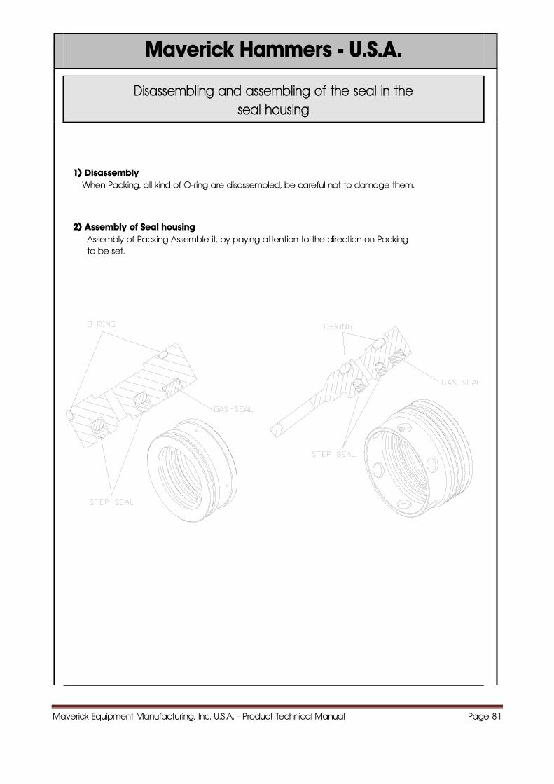
Disassembling and assembling of the seal in the seal housing
1) Disassembly When Packing, all kind of O-ring are disassembled, be careful not to damage them.
2) Assembly of Seal housing Assembly of Packing Assemble it, by paying attention to the direction on Packing
to be set.
Maverick Equipment Manufacturing, Inc. U.S.A. - Product Technical Manual Page 82
Maverick Hammers - U.S.A.
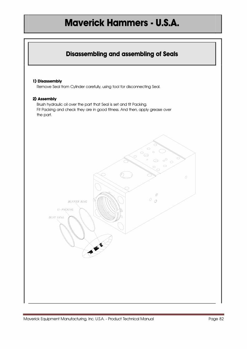
Disassembling and assembling of Seals
1) Disassembly Remove Seal from Cylinder carefully, using tool for disconnecting Seal.
2) Assembly Brush hydraulic oil over the part that Seal is set and fit Packing. Fit Packing and check they are in good fitness. And then, apply grease over
the part.
Maverick Equipment Manufacturing, Inc. U.S.A. - Product Technical Manual Page 83
Maverick Hammers - U.S.A.
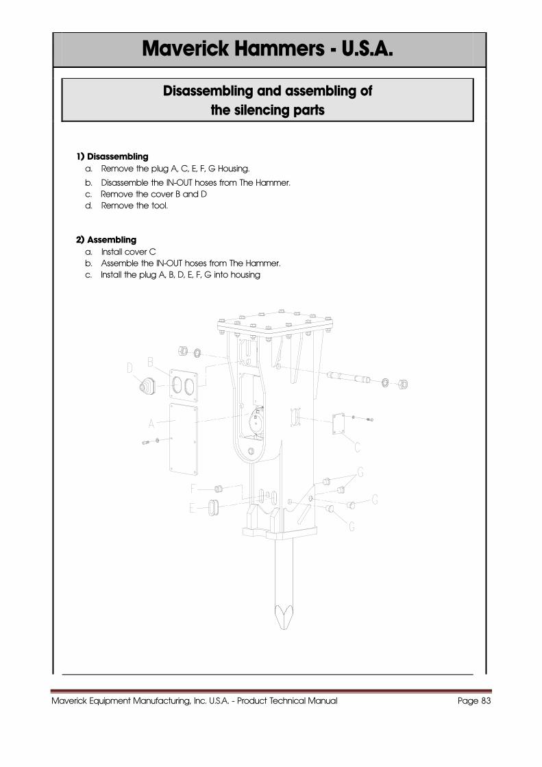
Disassembling and assembling of the silencing parts
1) Disassembling a. Remove the plug A, C, E, F, G Housing.
b. Disassemble the IN-OUT hoses from The Hammer. c. Remove the cover B and D d. Remove the tool. 2) Assembling a. Install cover C b. Assemble the IN-OUT hoses from The Hammer. c. Install the plug A, B, D, E, F, G into housing
Maverick Equipment Manufacturing, Inc. U.S.A. - Product Technical Manual Page 84
Maverick Hammers - U.S.A.
77..TTOORRQQUUEE
RREEFFEERREENNCCEESS
Maverick Equipment Manufacturing, Inc. U.S.A. - Product Technical Manual Page 85
Maverick Hammers - U.S.A.
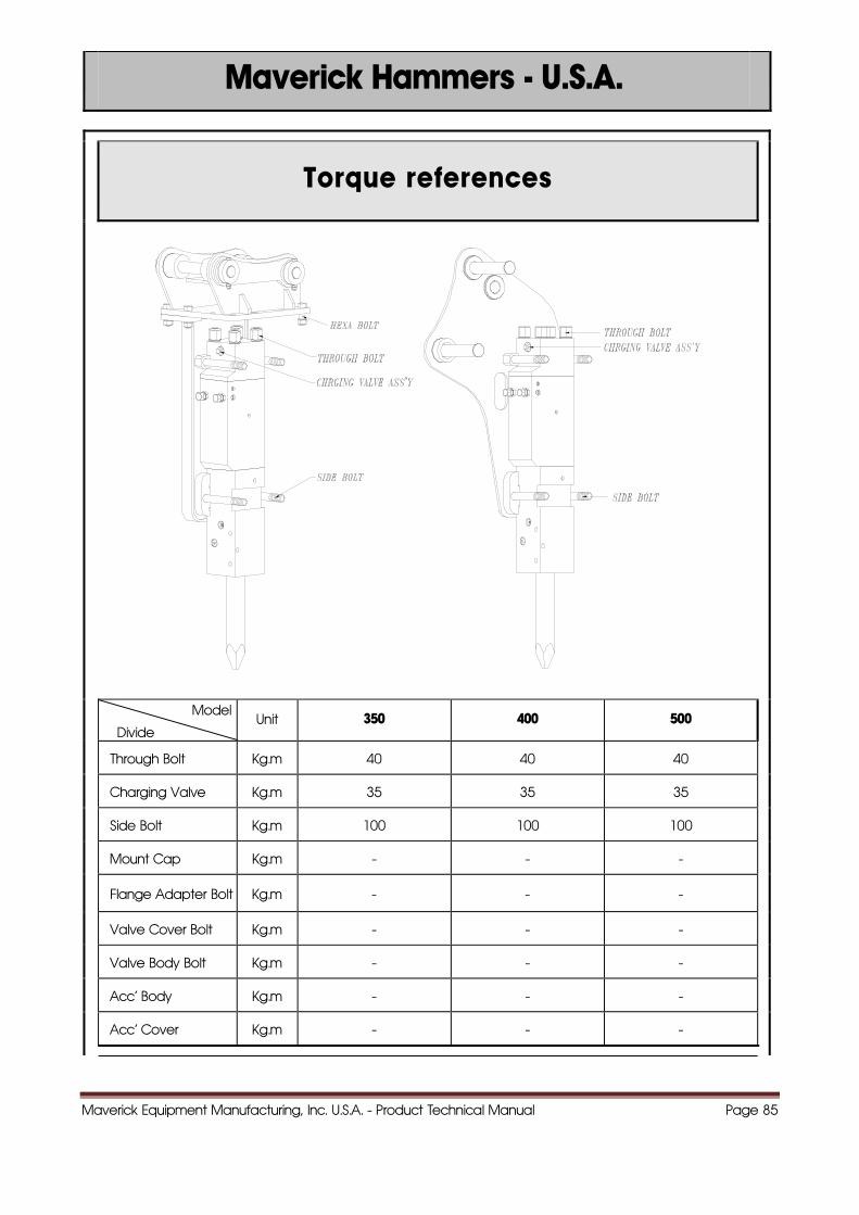
Torque references
Model
Divide Unit 350 400 500
Through Bolt Kg.m 40 40 40
Charging Valve Kg.m 35 35 35
Side Bolt Kg.m 100 100 100
Mount Cap Kg.m - - -
Flange Adapter Bolt Kg.m - - -
Valve Cover Bolt Kg.m - - -
Valve Body Bolt Kg.m - - -
Acc' Body Kg.m - - -
Acc' Cover Kg.m - - -
Maverick Equipment Manufacturing, Inc. U.S.A. - Product Technical Manual Page 86
Maverick Hammers - U.S.A.
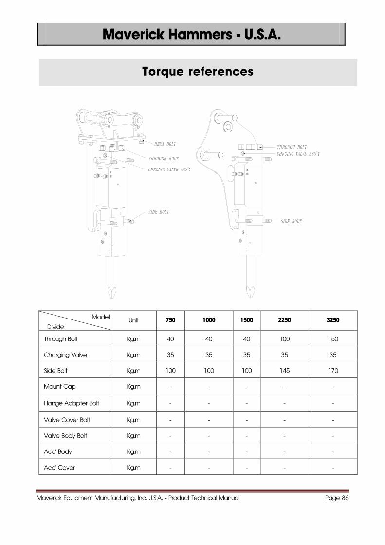
Torque references
Model
Divide Unit 750 1000 1500 2250 3250
Through Bolt Kg.m 40 40 40 100 150
Charging Valve Kg.m 35 35 35 35 35
Side Bolt Kg.m 100 100 100 145 170
Mount Cap Kg.m - - - - -
Flange Adapter Bolt Kg.m - - - - -
Valve Cover Bolt Kg.m - - - - -
Valve Body Bolt Kg.m - - - - -
Acc' Body Kg.m - - - - -
Acc' Cover Kg.m - - - - -
Maverick Equipment Manufacturing, Inc. U.S.A. - Product Technical Manual Page 87
Maverick Hammers - U.S.A.
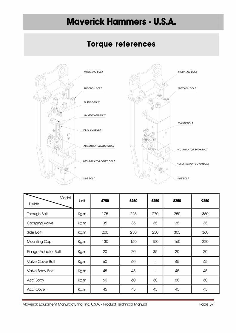
Torque references
SIDE BOLT
ACCUMULATOR COVER BOLT
ACCUMULATOR BODY BOLT
FLANGE BOLT
VALVE COVER BOLT
VALVE BOX BOLT
MOUNTING BOLT
THROUGH BOLT
SIDE BOLT
ACCUMULATOR COVER BOLT
ACCUMULATOR BODY BOLT
MOUNTING BOLT
THROUGH BOLT
FLANGE BOLT
Model
Divide Unit 4750 5250 6250 8250 9250
Through Bolt Kg.m 175 225 270 250 360
Charging Valve Kg.m 35 35 35 35 35
Side Bolt Kg.m 200 250 250 305 360
Mounting Cap Kg.m 130 150 150 160 220
Flange Adapter Bolt Kg.m 20 20 35 20 20
Valve Cover Bolt Kg.m 60 60 - 45 45
Valve Body Bolt Kg.m 45 45 - 45 45
Acc' Body Kg.m 60 60 60 60 60
Acc' Cover Kg.m 45 45 45 45 45
Maverick Equipment Manufacturing, Inc. U.S.A. - Product Technical Manual Page 88
88..VVAALLVVEE AADDJJUUSSTTEERR
CCOONNTTRROOLL
Maverick Equipment Manufacturing, Inc. U.S.A. - Product Technical Manual Page 89
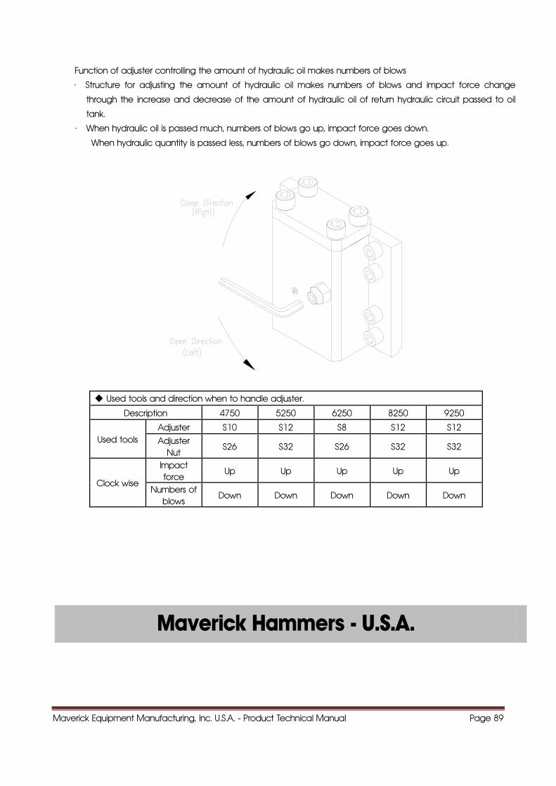
Function of adjuster controlling the amount of hydraulic oil makes numbers of blows
· Structure for adjusting the amount of hydraulic oil makes numbers of blows and impact force change
through the increase and decrease of the amount of hydraulic oil of return hydraulic circuit passed to oil
tank.
· When hydraulic oil is passed much, numbers of blows go up, impact force goes down.
When hydraulic quantity is passed less, numbers of blows go down, impact force goes up.
◆ Used tools and direction when to handle adjuster.
Description 4750 5250 6250 8250 9250
Used tools Adjuster S10 S12 S8 S12 S12
Adjuster Nut
S26 S32 S26 S32 S32
Clock wise
Impact force
Up Up Up Up Up
Numbers of blows
Down Down Down Down Down
Maverick Hammers - U.S.A.

Maverick Equipment Manufacturing, Inc. U.S.A. - Product Technical Manual Page 90
99..TTOOOOLL
Maverick Hammers - U.S.A.
Maverick Equipment Manufacturing, Inc. U.S.A. - Product Technical Manual Page 91
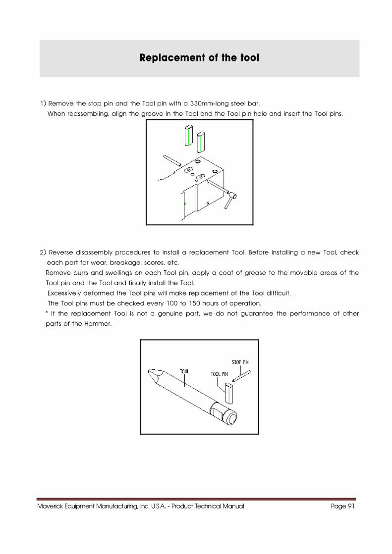
Replacement of the tool
1) Remove the stop pin and the Tool pin with a 330mm-long steel bar.
When reassembling, align the groove in the Tool and the Tool pin hole and insert the Tool pins.
2) Reverse disassembly procedures to install a replacement Tool. Before installing a new Tool, check
each part for wear, breakage, scores, etc.
Remove burrs and swellings on each Tool pin, apply a coat of grease to the movable areas of the
Tool pin and the Tool and finally install the Tool.
Excessively deformed the Tool pins will make replacement of the Tool difficult.
The Tool pins must be checked every 100 to 150 hours of operation.
* If the replacement Tool is not a genuine part, we do not guarantee the performance of other
parts of the Hammer.
Maverick Equipment Manufacturing, Inc. U.S.A. - Product Technical Manual Page 92
Maverick Hammers - U.S.A.
How to use tools properly
The purpose of this guide to enable you to advise your customer as to the correct application of
BH Demolition Tools and assist you to resolve complaints immediately they occur.
When a tool has apparently failed to give satisfactory service life, a visual inspection often quickly
resolves the cause and saves transport costs and frustration when warranty is rejected.
How a Demolition Tool Hammers Rock and Concrete
When the hammer piston strikes the top of a demolition tool, it sends a compressive stress wave
down to the working end of the tool. Provided the demolition tool is in contact with the rock or
concrete which requires breaking, it is this compressive stress wave which fractures the rock.
Immediately following the compressive stress wave, a tensile stress wave is formed due to the
hammer piston lifting from the top of the demolition tool. This cycle of compressive and tensile
stresses flowing down the tool of repeated for each hammer blow.
Obviously, anything that interferes with the 'strength' if the compressive stress wave during service,
for example 'free running' or bending of the demolition tool due to leverage, will result in loss of
Hammer efficiency of up to 80% and possible fatigue failure of the tool itself.
Cause and Effect of Fatigue
The continuous cycle of compressive and tensile stresses in the demolition tool, even under correct
operating conditions, create fatigue stress in the tool which can lead to the fatigue of a demolition
tool before it is worn out. Again, anything which interferes with the cycle of compressive and tensile
stresses will also increase the level of fatigue stresses will also increase the level of fatigue stress
being applied to the demolition tool and thus increase the risk of early fatigue failure of the tool.
Maverick Equipment Manufacturing, Inc. U.S.A. - Product Technical Manual Page 93
Maverick Hammers - U.S.A.
How to use tools properly
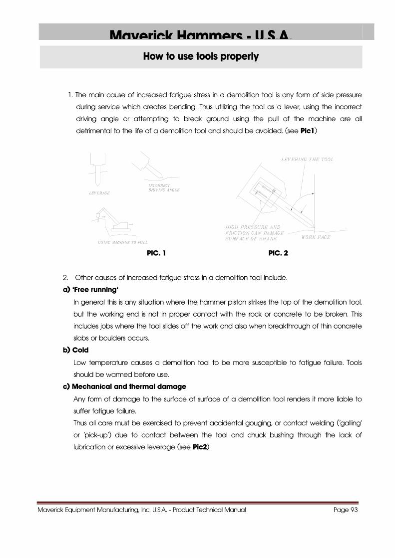
1. The main cause of increased fatigue stress in a demolition tool is any form of side pressure
during service which creates bending. Thus utilizing the tool as a lever, using the incorrect
driving angle or attempting to break ground using the pull of the machine are all
detrimental to the life of a demolition tool and should be avoided. (see Pic1)
PIC. 1 PIC. 2
2. Other causes of increased fatigue stress in a demolition tool include.
a) 'Free running'
In general this is any situation where the hammer piston strikes the top of the demolition tool,
but the working end is not in proper contact with the rock or concrete to be broken. This
includes jobs where the tool slides off the work and also when breakthrough of thin concrete
slabs or boulders occurs.
b) Cold
Low temperature causes a demolition tool to be more susceptible to fatigue failure. Tools
should be warmed before use.
c) Mechanical and thermal damage
Any form of damage to the surface of surface of a demolition tool renders it more liable to
suffer fatigue failure.
Thus all care must be exercised to prevent accidental gouging, or contact welding ('galling'
or 'pick-up') due to contact between the tool and chuck bushing through the lack of
lubrication or excessive leverage (see Pic2)
Maverick Equipment Manufacturing, Inc. U.S.A. - Product Technical Manual Page 94
Maverick Hammers U S A
How to use tools properly
d) Lubrication
Care must be taken to avoid metal to metal contact that, as a result of galling or pick-up,
could cause deep damage marks which, in turn, lead to the formation of fatigue cracks
and eventual failure of the demolition tool. Ensure that the shank of the demolition tool is
well lubricated before locating in the machine. Molybdenum bisulphide grease is
recommended for this application at three hourly intervals or as per manufactures
instruction.
e) Corrosion
A rusty demolition tool is more likely to suffer fatigue failure, thus keep tools well greased and
sheltered from the weather when not in use.
PIC. 3
Demolition Tool Fatigue Failure
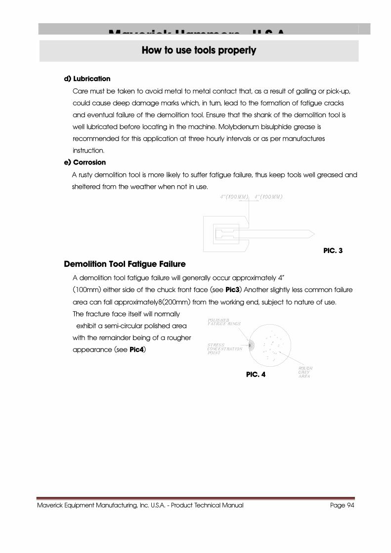
A demolition tool fatigue failure will generally occur approximately 4"
(100mm) either side of the chuck front face (see Pic3) Another slightly less common failure
area can fall approximately8(200mm) from the working end, subject to nature of use.
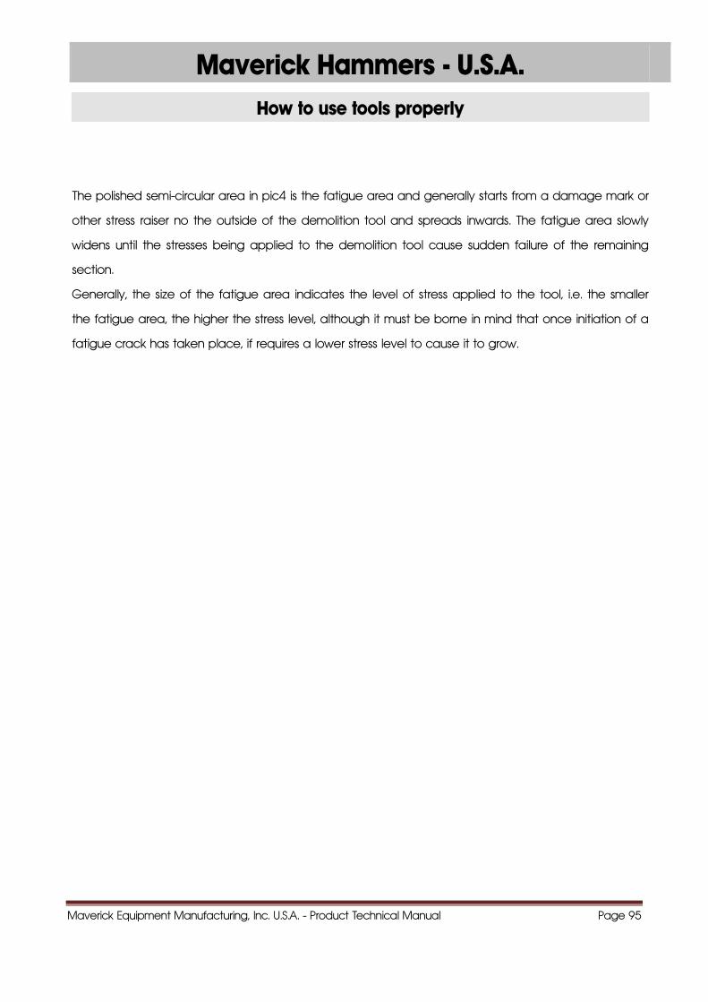
The fracture face itself will normally
exhibit a semi-circular polished area
with the remainder being of a rougher
appearance (see Pic4)
PIC. 4
Maverick Equipment Manufacturing, Inc. U.S.A. - Product Technical Manual Page 95
Maverick Hammers - U.S.A.
How to use tools properly
The polished semi-circular area in pic4 is the fatigue area and generally starts from a damage mark or
other stress raiser no the outside of the demolition tool and spreads inwards. The fatigue area slowly
widens until the stresses being applied to the demolition tool cause sudden failure of the remaining
section.
Generally, the size of the fatigue area indicates the level of stress applied to the tool, i.e. the smaller
the fatigue area, the higher the stress level, although it must be borne in mind that once initiation of a
fatigue crack has taken place, if requires a lower stress level to cause it to grow.

Maverick Equipment Manufacturing, Inc. U.S.A. - Product Technical Manual Page 96
1100..HHOOWW TTOO CCHHAARRGGEE NN22 GGAASS
Maverick Hammers - U.S.A.
Maverick Equipment Manufacturing, Inc. U.S.A. - Product Technical Manual Page 97
Back-head gas charging
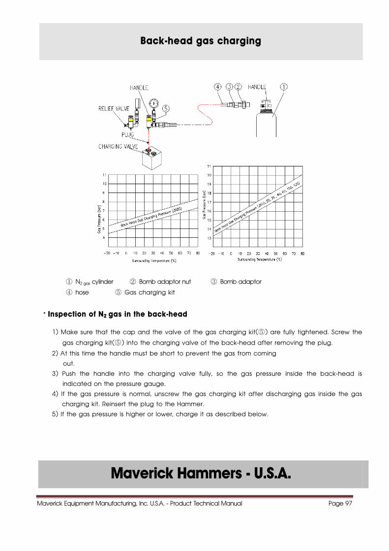
① N2 gas cylinder ② Bomb adaptor nut ③ Bomb adaptor
④ hose ⑤ Gas charging kit
* Inspection of N2 gas in the back-head
1) Make sure that the cap and the valve of the gas charging kit(⑤ ) are fully tightened. Screw the
gas charging kit(⑤ ) into the charging valve of the back-head after removing the plug.
2) At this time the handle must be short to prevent the gas from coming
out.
3) Push the handle into the charging valve fully, so the gas pressure inside the back-head is
indicated on the pressure gauge.
4) If the gas pressure is normal, unscrew the gas charging kit after discharging gas inside the gas
charging kit. Reinsert the plug to the Hammer.
5) If the gas pressure is higher or lower, charge it as described below.
Maverick Hammers - U.S.A.
Maverick Equipment Manufacturing, Inc. U.S.A. - Product Technical Manual Page 98
Back-head gas charging
1) Connect the charging hose(④ ) to N2 gas cylinder(① ) after screwing the bomb adapter(④) onto
adapter nut(② ) and installing than to the N2 gas cylinder.
2) Connect the gas charging kit(⑤ ) to the charging hose(④ ) after unscrewing the cap on the gas
charging kit.
3) Install the gas charging kit(⑤ ) to the charging valve of the Back-Head. At this time the handle
of the gas charging kit must be up position to prevent the gas from coming out.
4) Push the handle of the gas charging kit fully and turn the handle of the N2-gas cylinder counter
clockwise gradually to charge the Back-Head.
5) When the gas pressure exceeds 10% higher then the specified pressure, close the N2 gas
cylinder by turning the handle clockwise.
6) Leave the handle of gas charging kit up. generated pressure makes, it return back to original
position naturally.
7) Remove the charging hose(④ ) from the N2 gas cylinder(① ) and the gas charging kit (⑤ ), and
the screw the cap onto the gas charging kit.
8) Push the handle of the gas charging kit fully, and the gas pressure inside the back-head is
indicated on the pressure gauge. When the pressure is higher, discharge a small amount of gas
from the back-head repeatedly opening and closing the valve and then gas pressure falls to
the specified pressure.
9) When the gas pressure reaches to the specified pressure, close the valve and release the
handle.
10) Open the valve completely and discharge gas inside the gas charging kit. Remove the gas
charging kit from the charging valve of the Back-Head and install the plug to the charging
valve.
! WARNING ■ CHARGING GAS PRESSURE CHANGES ACCORDING TO THE TOOL CONDITION. LAY DOWN THE HAMMER AND LET THE
TOOL EXTEND FULLY.
■ STAY CLEAR OF THE TOOL WHILE CHARGING THE HAMMER WITH GAS. THE TOOL MAY BE IMPACTED BY THE PISTON
AND FORCED OUT ABRUPTLY.
■ WHEN THE THROUGH BOLTS ARE CHANGED THE N2 GAS MUST BE DISCHARGED WITH THE BACK HEAD, AS IT IS HIGHLY
PRESSURIZED.
■ USE NITROGEN GAS ONLY.
■ SEE "CONVERSION TABLE FOR CHARGING N2 GAS PRESSURE TO THE BACK HEAD"
Maverick Equipment Manufacturing, Inc. U.S.A. - Product Technical Manual Page 99
Maverick Hammers - U.S.A.
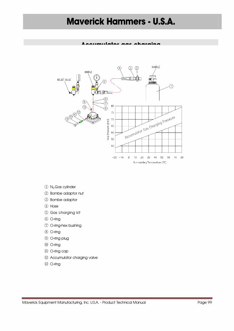
Accumulator gas charging
① N2-Gas cylinder
② Bombe adaptor nut
③ Bombe adaptor
④ Hose
⑤ Gas charging kit
⑥ O-ring
⑦ O-ring-hex bushing
⑧ O-ring
⑨ O-ring plug
⑩ O-ring
⑪ O-ring cap
⑫ Accumulator charging valve
⑬ O-ring
Maverick Equipment Manufacturing, Inc. U.S.A. - Product Technical Manual Page 100
Maverick Hammers - U.S.A.
Accumulator gas charging
1) Connect the charging hose(④ ) to the N2-Gas cylinder(① ) after screwing the bomb
adapter(③ ) on to the adapter, the nut(② ) and installing to the N2-Gas cylinder.
2) Connect the gas charging kit(⑤ ) to the charging hose(④ ) after unscrewing the cap on the
gas charging kit.
3) Remove the cap(⑪ ) from the accumulator and tighten the charging valve(⑫ ) fully.
4) Check if the o-rings (⑥ )(⑧ ) are installed to the bushing(⑦ ). Remove the plug(⑨ ) and screw
the bushing.
5) Loosen the accumulator charging valve(⑫ ) after checking if the bushing(⑦ ) is installed to the
gas charging kit.
6) Turn the handle of the N2-Gas cylinder counter clockwise slowly to charge gas.
7) Charge gas in accordance with the conversion table for charging N2-Gas pressure to the
accumulator.
8) Turn the handle of the N2-Gas cylinder clockwise to close the cock.
9) Close the accumulator charging valve.
10) Loosen the valve of the gas charging kit to discharge the N2-Gas remaining in the charging
hose.
11) Remove the charging hose, the gas charging kit and the bushing and tighten the plug(⑨ ) and
cap(⑪ ).
Maverick Equipment Manufacturing, Inc. U.S.A. - Product Technical Manual Page 101
Maverick Hammers - U.S.A.
Caution for gas charging
■ Be sure to use the gas charging kit for charging the N2 gas. If charging gas leaks directly from the
cylinder, the diaphragm may be broken off.
■ If charging for handling N2 gas to only the accumulator, make sure that the accumulator body and
the cover are tightened fully.
1) Make sure the cap and the valve of the gas charging kit(⑤ ) are fully tightened.
2) Remove the cap(⑪ ) from the accumulator and tighten the charging valve(⑫ ) fully.
3) Check if the O-rings(⑥ )(⑧ ) are installed to the bushing(⑦ ). Remove the plug(⑨ ) and the screw in
the bushing.
4) Install the bushing(⑦ ) to the gas charging kit(⑤ ).
5) Loosen the charging valve(⑫ ) gradually. The charging pressure is indicated on the pressure gauge.
6) Close the valve clockwise when the gas pressure is normal. When the gas pressure is higher, repeat
loosening and tightening the valve of gas charging kit. The pressure is lowered gradually.
7) Loosen the valve of the gas charging kit to discharge the N2-gas in the gas charging kit(⑤ )
8) Remove the gas charging kit(⑤ ) and tighten the plug(⑨ ) and the cap(⑪ ).
! WARNING ■ USE SPECIAL CARE TO HANDLE AND STORE THE N2-GAS CYLINDER AS IT IS A HIGHLY PRESSURIZED CONTAINER.
■ USE NITROGEN GAS ONLY.
■ STANDARD ACCUMULATOR GAS PRESSURE 55kg/cm2/780PSI AT 20 /68 AMBIENT TEMPERATURE. DO NOT OVER
PRESSURIZE THE ACCUMULATOR.
■ SEE "CONVERSION TABLE FOR CHARGING N2-GAS PRESSURE TO THE ACCUMULATOR".

Maverick Equipment Manufacturing, Inc. U.S.A. - Product Technical Manual Page 102
1111..CCHHEECCKK LLIISSTT FFOORR MMAAIINNTTEENNAANNCCEE
Maverick Hammers - U.S.A.
Maverick Equipment Manufacturing, Inc. U.S.A. - Product Technical Manual Page 103
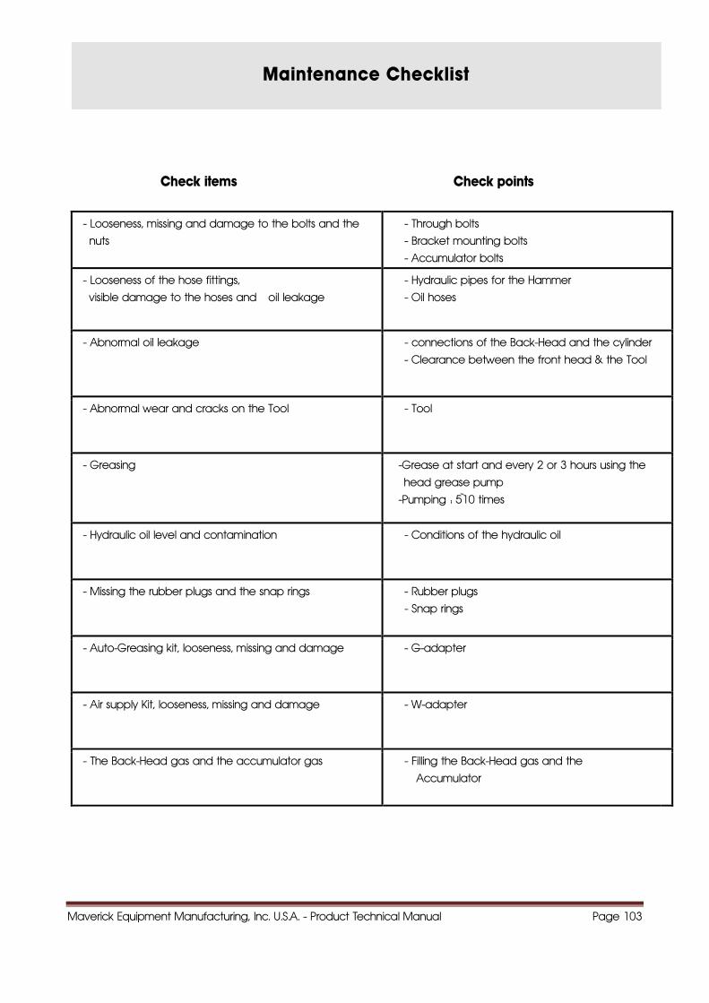
Maintenance Checklist
Check items Check points
- Looseness, missing and damage to the bolts and the
nuts
- Through bolts
- Bracket mounting bolts
- Accumulator bolts
- Looseness of the hose fittings,
visible damage to the hoses and oil leakage
- Hydraulic pipes for the Hammer
- Oil hoses
- Abnormal oil leakage - connections of the Back-Head and the cylinder
- Clearance between the front head & the Tool
- Abnormal wear and cracks on the Tool - Tool
- Greasing -Grease at start and every 2 or 3 hours using the
head grease pump
-Pumping : 5~10 times
- Hydraulic oil level and contamination - Conditions of the hydraulic oil
- Missing the rubber plugs and the snap rings - Rubber plugs
- Snap rings
- Auto-Greasing kit, looseness, missing and damage - G-adapter
- Air supply Kit, looseness, missing and damage - W-adapter
- The Back-Head gas and the accumulator gas - Filling the Back-Head gas and the
Accumulator
Maverick Equipment Manufacturing, Inc. U.S.A. - Product Technical Manual Page 104
Maverick Hammers - U.S.A.
1122..GGUUIIDDEE FFOORR TTRROOUUBBLLEE SSHHOOOOTTIINNGG
Maverick Equipment Manufacturing, Inc. U.S.A. - Product Technical Manual Page 105
Maverick Hammers - U.S.A.
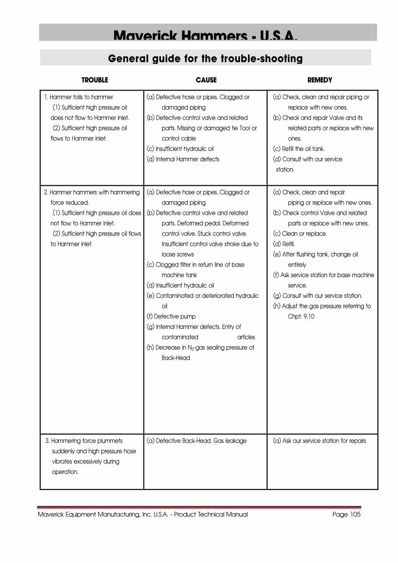
General guide for the trouble-shooting
TROUBLE CAUSE REMEDY
1. Hammer fails to hammer
(1) Sufficient high pressure oil
does not flow to Hammer inlet.
(2) Sufficient high pressure oil
flows to Hammer inlet.
(a) Defective hose or pipes. Clogged or
damaged piping
(b) Defective control valve and related
parts. Missing or damaged tie Tool or
control cable
(c) Insufficient hydraulic oil
(d) Internal Hammer defects
(a) Check, clean and repair piping or
replace with new ones.
(b) Check and repair Valve and its
related parts or replace with new
ones.
(c) Refill the oil tank.
(d) Consult with our service
station.
2. Hammer hammers with hammering
force reduced.
(1) Sufficient high pressure oil does
not flow to Hammer inlet.
(2) Sufficient high pressure oil flows
to Hammer inlet.
(a) Defective hose or pipes. Clogged or
damaged piping
(b) Defective control valve and related
parts. Deformed pedal. Deformed
control valve. Stuck control valve.
Insufficient control valve stroke due to
loose screws
(c) Clogged filter in return line of base
machine tank
(d) Insufficient hydraulic oil
(e) Contaminated or deteriorated hydraulic
oil
(f) Defective pump
(g) Internal Hammer defects. Entry of
contaminated articles
(h) Decrease in N2-gas sealing pressure of
Back-Head
(a) Check, clean and repair
piping or replace with new ones.
(b) Check control Valve and related
parts or replace with new ones.
(c) Clean or replace.
(d) Refill.
(e) After flushing tank, change oil
entirely
(f) Ask service station for base machine
service.
(g) Consult with our service station.
(h) Adjust the gas pressure referring to
Chpt. 9,10
3. Hammering force plummets
suddenly and high pressure hose
vibrates excessively during
operation.
(a) Defective Back-Head. Gas leakage (a) Ask our service station for repairs
Maverick Equipment Manufacturing, Inc. U.S.A. - Product Technical Manual Page 106
Maverick Hammers - U.S.A.
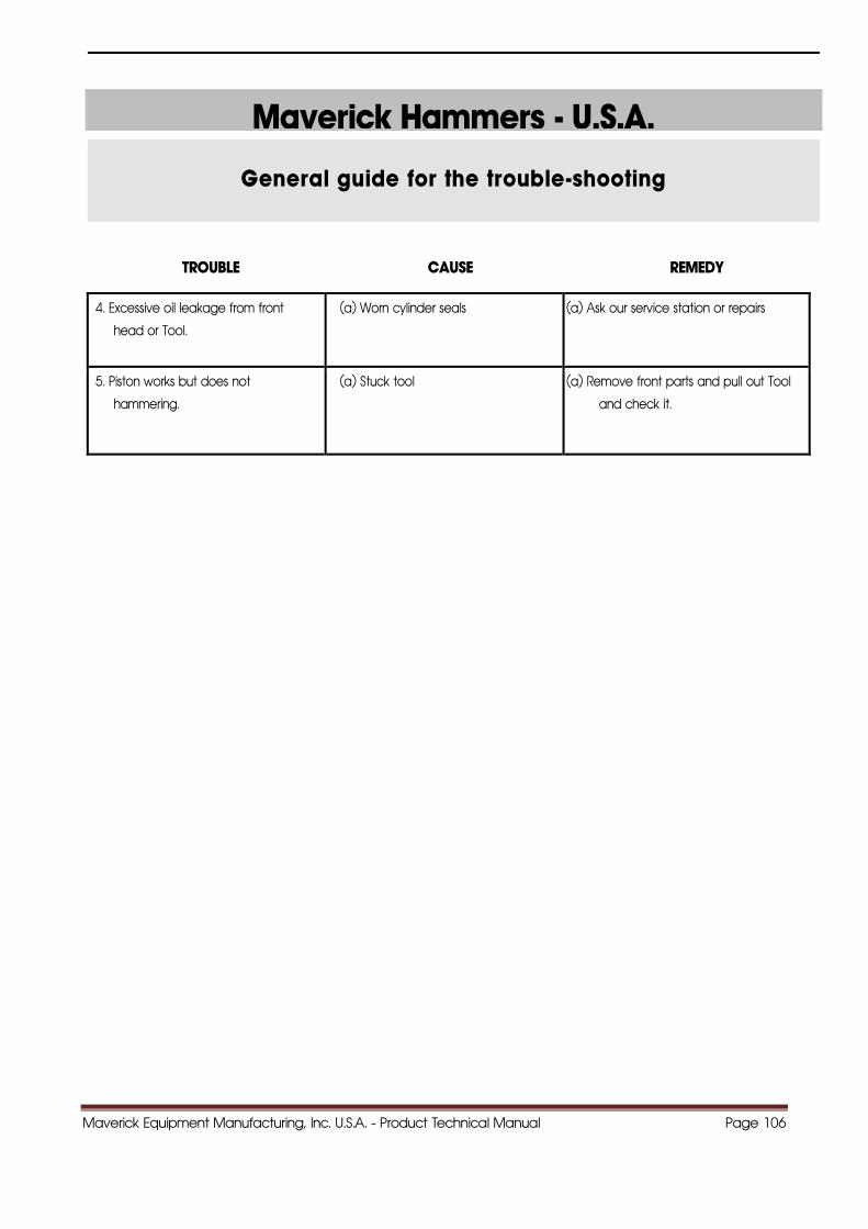
General guide for the trouble-shooting
TROUBLE CAUSE REMEDY
4. Excessive oil leakage from front
head or Tool.
(a) Worn cylinder seals (a) Ask our service station or repairs
5. Piston works but does not
hammering.
(a) Stuck tool (a) Remove front parts and pull out Tool
and check it.

Maverick Equipment Manufacturing, Inc. U.S.A. - Product Technical Manual Page 107
1133..WWEEAARR LLIIMMIITT RREEFFEERREENNCCEESS OOFF TTHHEE MMAAIINN PPAARRTTSS
Maverick Hammers - U.S.A.
Maverick Equipment Manufacturing, Inc. U.S.A. - Product Technical Manual Page 108
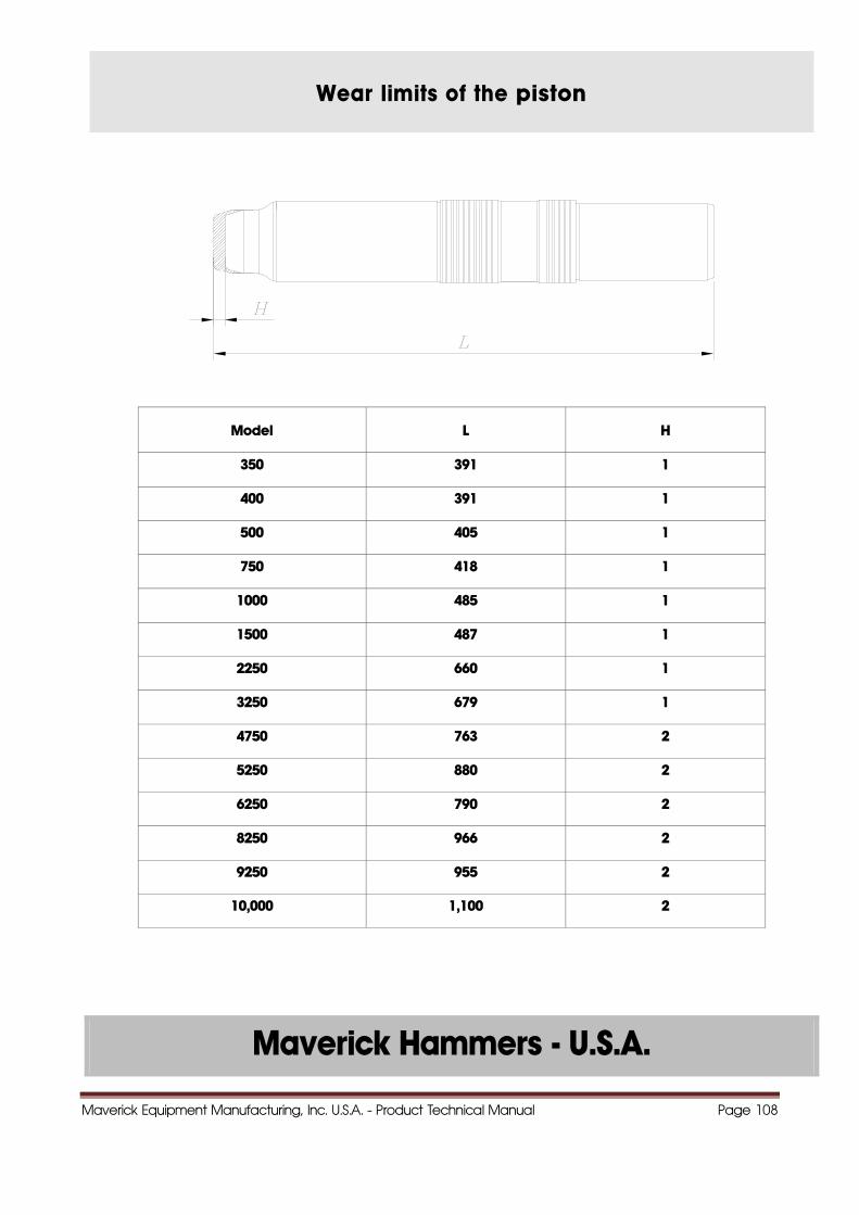
Wear limits of the piston
Model L H
350 391 1
400 391 1
500 405 1
750 418 1
1000 485 1
1500 487 1
2250 660 1
3250 679 1
4750 763 2
5250 880 2
6250 790 2
8250 966 2
9250 955 2
10,000 1,100 2
Maverick Hammers - U.S.A.
Maverick Equipment Manufacturing, Inc. U.S.A. - Product Technical Manual Page 109
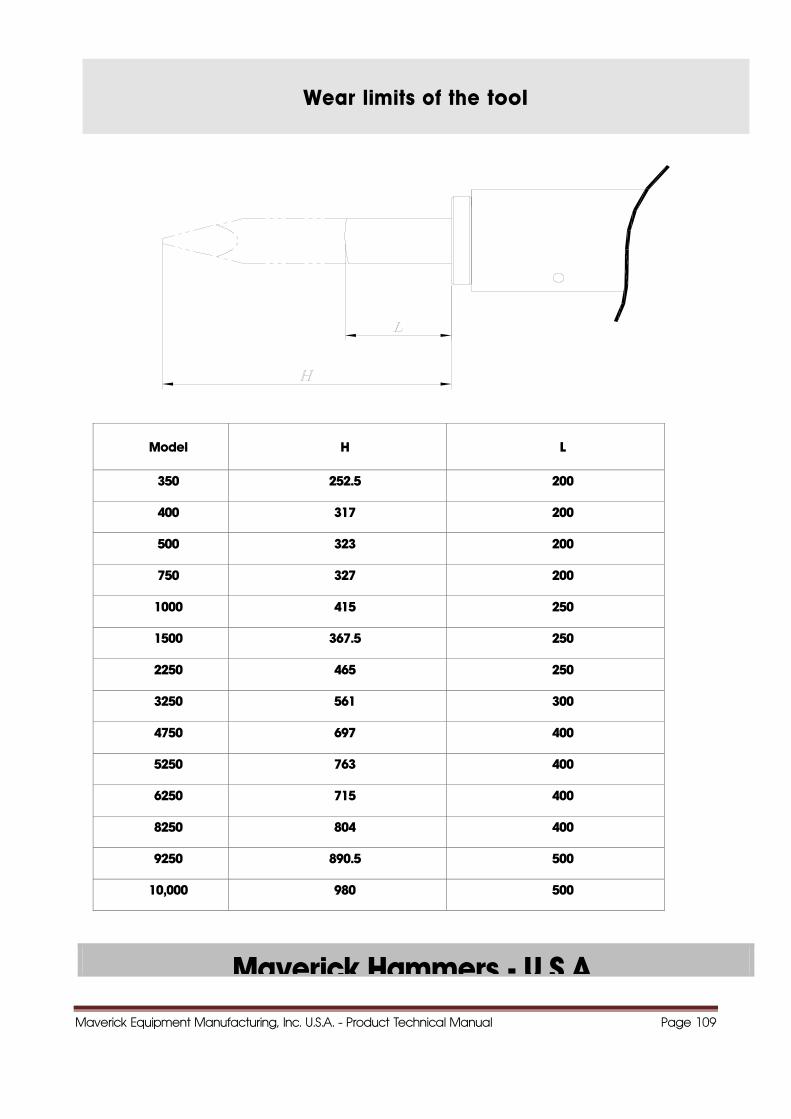
Wear limits of the tool
Model H L
350 252.5 200
400 317 200
500 323 200
750 327 200
1000 415 250
1500 367.5 250
2250 465 250
3250 561 300
4750 697 400
5250 763 400
6250 715 400
8250 804 400
9250 890.5 500
10,000 980 500
Maverick Hammers - U.S.A.
Maverick Equipment Manufacturing, Inc. U.S.A. - Product Technical Manual Page 110
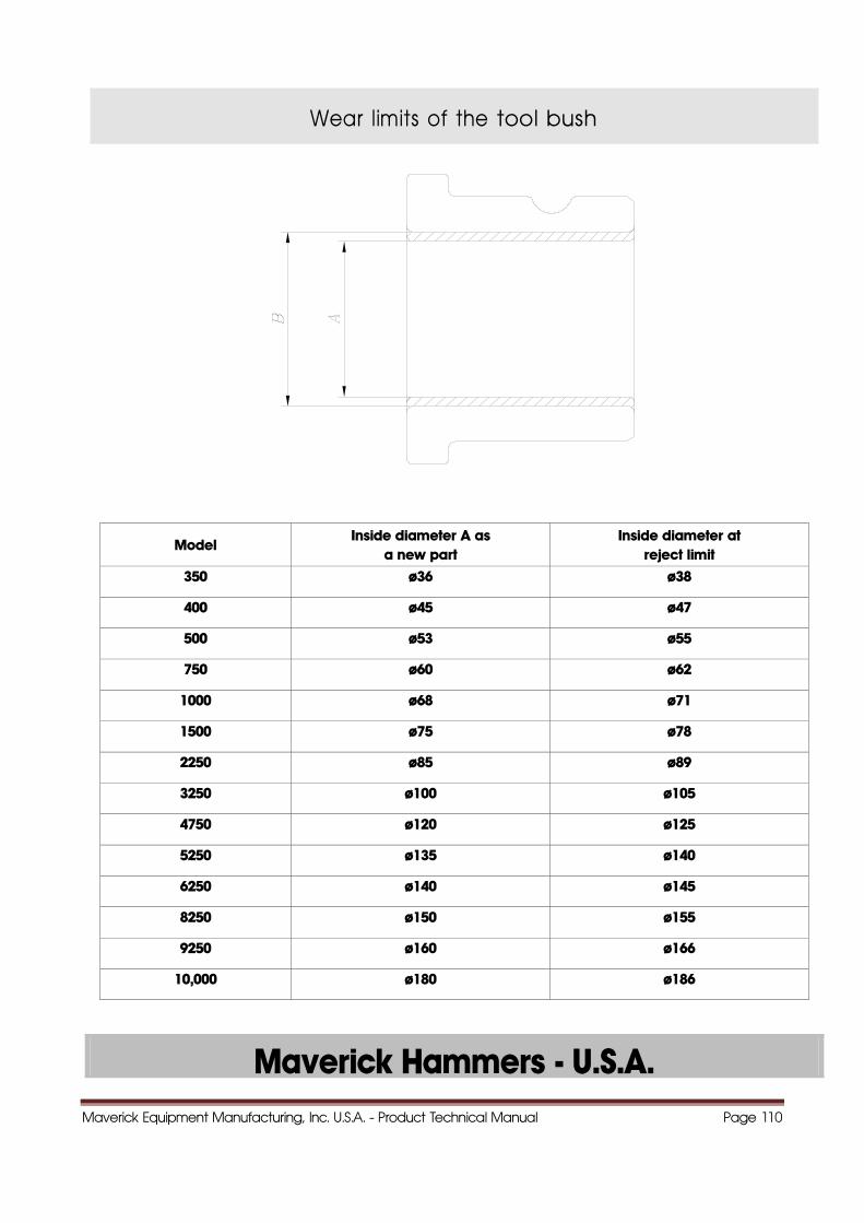
Wear limits of the tool bush
Model Inside diameter A as
a new part Inside diameter at
reject limit 350 ø36 ø38
400 ø45 ø47
500 ø53 ø55
750 ø60 ø62
1000 ø68 ø71
1500 ø75 ø78
2250 ø85 ø89
3250 ø100 ø105
4750 ø120 ø125
5250 ø135 ø140
6250 ø140 ø145
8250 ø150 ø155
9250 ø160 ø166
10,000 ø180 ø186
Maverick Hammers - U.S.A.
Maverick Equipment Manufacturing, Inc. U.S.A. - Product Technical Manual Page 111
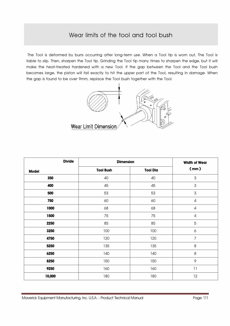
Wear limits of the tool and tool bush
The Tool is deformed by burrs occurring after long-term use. When a Tool tip is worn out, The Tool is
liable to slip. Then, sharpen the Tool tip. Grinding the Tool tip many times to sharpen the edge, but it will
make the heat-treated hardened with a new Tool. If the gap between the Tool and the Tool bush
becomes large, the piston will fail exactly to hit the upper part of the Tool, resulting in damage. When
the gap is found to be over 9mm, replace the Tool bush together with the Tool.
Divide
Model
Dimension Width of Wear
( mm ) Tool Bush Tool Dia
350 40 40 3
400 45 45 3
500 53 53 3
750 60 60 4
1000 68 68 4
1500 75 75 4
2250 85 85 5
3250 100 100 6
4750 120 120 7
5250 135 135 8
6250 140 140 8
8250 150 150 9
9250 160 160 11
10,000 180 180 12

Maverick Equipment Manufacturing, Inc. U.S.A. - Product Technical Manual Page 112
M i k H U S A
Wear limits of the tool pin
Model L ( øD ) H
350 ø24.4 2
400 ø24.4 2
500 ø24.4 2
750 ø30 2
1000 ø30 2
1500 ø30 2
2250 54 2
3250 60 3
4750 72 3
5250 80 3
6250 90.5 3
8250 90.5 3
9250 110 3
10,000 125 4
Maverick Equipment Manufacturing, Inc. U.S.A. - Product Technical Manual Page 113
Maverick Hammers - U.S.A.
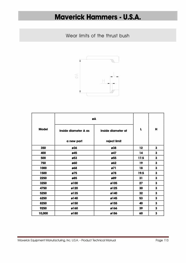
Wear limits of the thrust bush
Model
øA
L H Inside diameter A as Inside diameter at
a new part reject limit
350 ø36 ø38 12 3
400 ø45 ø47 14 3
500 ø53 ø55 17.5 3
750 ø60 ø62 19 3
1000 ø68 ø71 18 3
1500 ø75 ø78 19.5 3
2250 ø85 ø89 31 3
3250 ø100 ø105 27 3
4750 ø120 ø125 30 3
5250 ø135 ø140 32 3
6250 ø140 ø145 53 3
8250 ø150 ø155 40 3
9250 ø160 ø166 39 3
10,000 ø180 ø186 60 3
Maverick Equipment Manufacturing, Inc. U.S.A. - Product Technical Manual Page 114
1144..HHYYDDRRAAUULLIICC OOIILL
Maverick Hammers - U.S.A.
Maverick Equipment Manufacturing, Inc. U.S.A. - Product Technical Manual Page 115
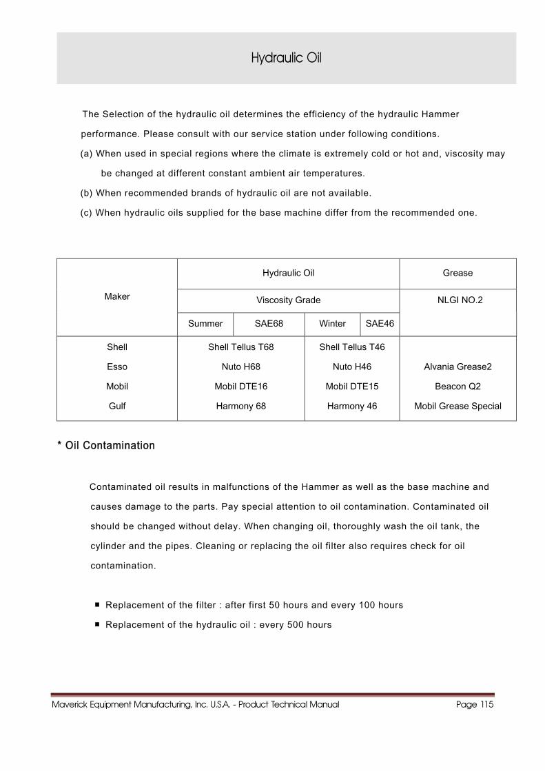
Hydraulic Oil
The Selection of the hydraulic oil determines the efficiency of the hydraulic Hammer
performance. Please consult with our service station under following conditions.
(a) When used in special regions where the climate is extremely cold or hot and, viscosity may
be changed at different constant ambient air temperatures.
(b) When recommended brands of hydraulic oil are not available.
(c) When hydraulic oils supplied for the base machine differ from the recommended one.
Maker
Hydraulic Oil Grease
Viscosity Grade NLGI NO.2
Summer SAE68 Winter SAE46
Shell
Esso
Mobil
Gulf
Shell Tellus T68
Nuto H68
Mobil DTE16
Harmony 68
Shell Tellus T46
Nuto H46
Mobil DTE15
Harmony 46
Alvania Grease2
Beacon Q2
Mobil Grease Special
* Oil Contamination
Contaminated oil results in malfunctions of the Hammer as well as the base machine and
causes damage to the parts. Pay special attention to oil contamination. Contaminated oil
should be changed without delay. When changing oil, thoroughly wash the oil tank, the
cylinder and the pipes. Cleaning or replacing the oil filter also requires check for oil
contamination.
■ Replacement of the filter : after first 50 hours and every 100 hours
■ Replacement of the hydraulic oil : every 500 hours
Maverick Equipment Manufacturing, Inc. U.S.A. - Product Technical Manual Page 116
Maverick Hammers - U.S.A.
1155..OOPPTTIIOONNSS
Maverick Equipment Manufacturing, Inc. U.S.A. - Product Technical Manual Page 117
Maverick Hammers - U.S.A.
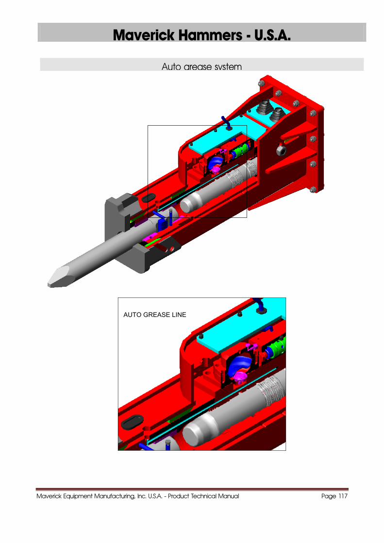
Auto grease system
AUTO GREASE LINE
Maverick Equipment Manufacturing, Inc. U.S.A. - Product Technical Manual Page 118
Maverick Hammers - U.S.A.
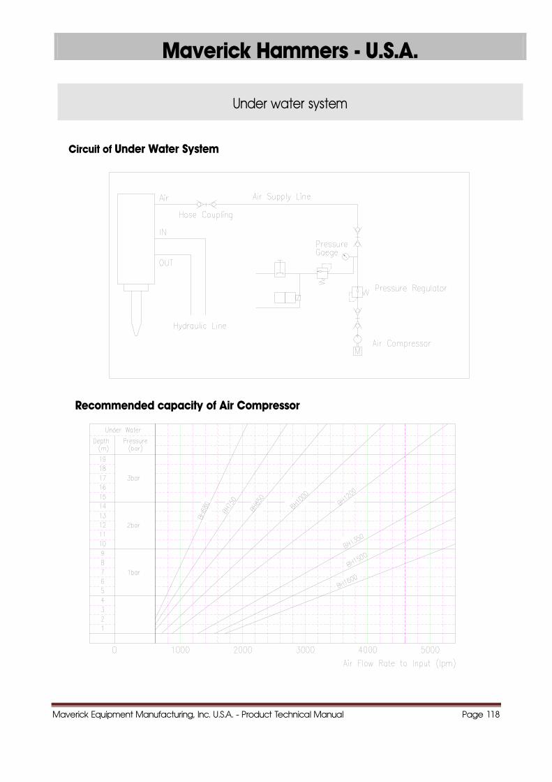
Under water system
Circuit of Under Water System
Recommended capacity of Air Compressor
Maverick Equipment Manufacturing, Inc. U.S.A. - Product Technical Manual Page 119
Maverick Hammers - U.S.A.
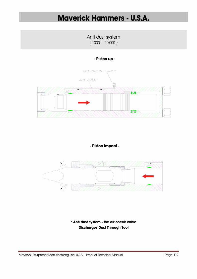
Anti dust system ( 1000 ~ 10,000 )
- Piston up -
- Piston impact -
* Anti dust system - the air check valve
Discharges Dust Through Tool
Maverick Equipment Manufacturing, Inc. U.S.A. - Product Technical Manual Page 120
NOTES ________________________________________________________________________________________________ ________________________________________________________________________________________________ ________________________________________________________________________________________________ ________________________________________________________________________________________________ ________________________________________________________________________________________________ ________________________________________________________________________________________________ ________________________________________________________________________________________________ ________________________________________________________________________________________________ ________________________________________________________________________________________________ ________________________________________________________________________________________________ ________________________________________________________________________________________________ ________________________________________________________________________________________________ ________________________________________________________________________________________________ ________________________________________________________________________________________________