Maurel Et Al. - 2002 - A Biomechanical Musculoskeletal Model of Human Upper Limb for Dynamic...
17
A Biomechanical Musculoskeletal Model of Human Upper Limb for Dynamic Simulation W. Maurel 1 , D. Thalmann 1 , P. Hoffmeyer 2 P. Beylot 3 , P. Gingins 3 , P. Kalra 3 , N. Magnenat Thalmann 3 (1) Computer Graphics Laboratory, Swiss Federal Institute of Technology, DI-LIG, EPFL, CH-1015 Lausanne, Switzerland, Email:{maurel,thalmann}glig.di.epfl.ch (2) Hopital Cantonal Universitaire - Clinique d’orthopédie, CH-1211 Geneve (3) MIRALab, C.U.I., University of Geneva, CH-1211 Geneva, Switzerland Abstract. In this paper, we provide the biomechanical model of human upper limb we have designed an d applied to the th ree-dimensional left human arm reconstructed from the Visible Human imaging Dataset. This model includes the mechanical properties for bones, joints and muscles lines of action. This work has been done as a part of the European Esprit Project CHARM. Its objective is to develop a Comprehensive Human Animation Resource Model allowing the dynamic simulation of complex musculoskeletal systems, including finite element deformation of soft-tissues and muscul ar contr act ion . In our approach, simplifications have been done so as to ensure the feasibility of the project while preserving the biomechanical validity of the model. Animations: http://ligwww.epfl.ch/~maurel/EGCAS96.html 1 Introduction The European Esprit Project CHARM involving several universities proposes the development of a comprehensive human resource data base, allowing the dynamic simulation of complex musculoskeletal systems, including finite element defo rmat ion of soft-tissues and muscular contraction [CHARM 93]. To begin with the development, we have chosen to model the human arm and shoulder, which has been reported to be one of the most complex articulations of the human body [Engin 80]. The reason for this choice lies in the confidence that beginning with the harder is more likel y to ensure we can achieve the simpler. We have thus deve loped a biomechanical model of the human upper limb including biomechan ical properties for bones, joints, and muscle lines of action, as required for a proper dynamic analysis [Helm 92]. In the project, this model will serve as a concrete basis for the development of the topological data structure [Kalra 95] and the various tools needed to perform its edition, dynamic analysis, motion control and rendering. To simplify the problem, we have considered the hand as a rigid prolongation of the forearm, approximated the arm segments by rigid cylinders, assumed the articulations as ideal kinematic joints and modeled the muscles according to anatomical criteria only. However, our choices have focused on preserving the biomechanical validity of the model and the easy interpretation of the parameters by practitioners. Our constraints have been to meet the objective of an interactive application as to ensure that the following analysis, especially the finite element modeling, are feasible.
-
Upload
koushikbakshi -
Category
Documents
-
view
219 -
download
0
Transcript of Maurel Et Al. - 2002 - A Biomechanical Musculoskeletal Model of Human Upper Limb for Dynamic...

7/18/2019 Maurel Et Al. - 2002 - A Biomechanical Musculoskeletal Model of Human Upper Limb for Dynamic Simulation
http://slidepdf.com/reader/full/maurel-et-al-2002-a-biomechanical-musculoskeletal-model-of-human-upper 1/16
A Biomechanical Musculoskeletal Model of Human Upper Limb for Dynamic Simulation
W. Maurel1, D. Thalmann1, P. Hoffmeyer2
P. Beylot3
, P. Gingins3
, P. Kalra3
, N. Magnenat Thalmann3
(1) Computer Graphics Laboratory, Swiss Federal Institute of Technology, DI-LIG,
EPFL, CH-1015 Lausanne, Switzerland, Email:{maurel,thalmann}glig.di.epfl.ch
(2) Hopital Cantonal Universitaire - Clinique d’orthopédie, CH-1211 Geneve
(3) MIRALab, C.U.I., University of Geneva, CH-1211 Geneva, Switzerland
Abstract. In this paper, we provide the biomechanical model of human upper
limb we have designed and applied to the three-dimensional left human arm
reconstructed from the Visible Human imaging Dataset. This model includesthe mechanical properties for bones, joints and muscles lines of action. This
work has been done as a part of the European Esprit Project CHARM. Its
objective is to develop a Comprehensive Human Animation Resource Model
allowing the dynamic simulation of complex musculoskeletal systems,
including finite element deformation of soft-tissues and muscular contr act ion.
In our approach, simplifications have been done so as to ensure the feasibility
of the project while preserving the biomechanical validity of the model.
Animations: http://ligwww.epfl.ch/~maurel/EGCAS96.html
1 Introduction
The European Esprit Project CHARM involving several universities proposes the
development of a comprehensive human resource data base, allowing the dynamic
simulation of complex musculoskeletal systems, including finite element deformation
of soft-tissues and muscular contraction [CHARM 93]. To begin with the
development, we have chosen to model the human arm and shoulder, which has been
reported to be one of the most complex articulations of the human body [Engin 80].The reason for this choice lies in the confidence that beginning with the harder is
more likely to ensure we can achieve the simpler. We have thus developed a
biomechanical model of the human upper limb including biomechanical properties for
bones, joints, and muscle lines of action, as required for a proper dynamic analysis
[Helm 92]. In the project, this model will serve as a concrete basis for the
development of the topological data structure [Kalra 95] and the various tools needed

7/18/2019 Maurel Et Al. - 2002 - A Biomechanical Musculoskeletal Model of Human Upper Limb for Dynamic Simulation
http://slidepdf.com/reader/full/maurel-et-al-2002-a-biomechanical-musculoskeletal-model-of-human-upper 2/16
In this paper, we provide first a brief description of the musculoskeletal anatomy of
the human upper limb with an analysis of the joint kinematics and muscular
synergism. We then present a survey of the major biomechanical models which have
been previously developed [Engin 89(a,b), Högfors 91, Helm 94b]. Then we provide a
complete description of our model including bone mechanical properties, joint
kinematics and muscle topology. As a result of the approach, we have used our
topological modeling tool to apply the theoretical model to the 3D left human arm we
have reconstructed from the Visible Human (male) Dataset, provided by the U.S.
National Library of Medecine [Beylot 96].
2 Human Arm Anatomy
In order to develop a consistent topological data structure, a preliminary modeling of the musculoskeletal structure is necessary. Since biomechanical modeling is intended,
it is natural to begin with the observation of the system components and their motion
before modeling. In the following section, basic anatomical descriptions of the upper
limb are presented to outline various structures involved in its mechanics.
2.1 Skeletal structure
The upper limb is composed of three chained mechanisms, the shoulder girdle, the
elbow and the wrist, whose association allows a wide range of combined motion, andconfers to the human arm the highest mobility in the human body. Due to the
complexity of the hand mechanics, the wrist was not studied and the hand was taken
as another rigid segment in the extension of the forearm. Considering bones in pairs,
seven joints may be distinguished: the sterno-clavicular joint , which articulates the
clavicle by its proximal end onto the sternum, the acromio-clavicular joint, which
articulates the scapula by its acromion onto the distal end of the clavicle, the scapulo-
thoracic joint, which allows the scapula to glide on the thorax, the gleno-humeral
joint, which allows the humeral head to rotate in the glenoid fossa of the scapula
[Kapandji 80], the ulno-humeral and the humero-radial joints, which articulate both
ulna and radius on the distal end of the humerus, and finally the ulno-radial joint
where both distal ends of ulna and radius join together [Chao 78].
Assuming translations negligible compared to rotations, all, except the scapulo-
thoracic joint, are usually assumed as ball and socket joint, having more or less 3
i l d f f d ( ) Th l h i j i i i l i
7/18/2019 Maurel Et Al. - 2002 - A Biomechanical Musculoskeletal Model of Human Upper Limb for Dynamic Simulation
http://slidepdf.com/reader/full/maurel-et-al-2002-a-biomechanical-musculoskeletal-model-of-human-upper 3/16
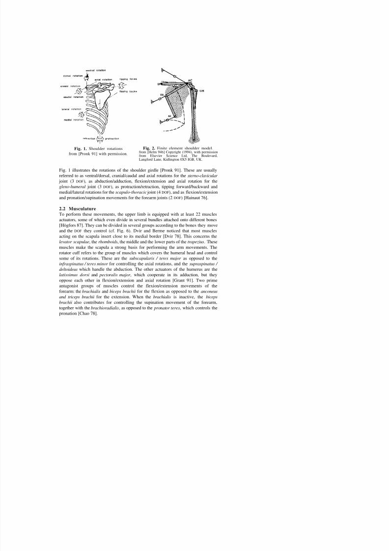
Fig. 1. Shoulder rotations
from [Pronk 91] with permission.
Fig. 2. Finite element shoulder model.from [Helm 94b] Copyright (1994), with permissionfrom Elsevier Science Ltd, The Boulevard,Langford Lane, Kidlington 0X5 IGB, UK.
Fig. 1 illustrates the rotations of the shoulder girdle [Pronk 91]. These are usually
referred to as ventral/dorsal, cranial/caudal and axial rotations for the sterno-clavicular
joint (3 DOF), as abduction/adduction, flexion/extension and axial rotation for the
gleno-humeral joint (3 DOF), as protraction/retraction, tipping forward/backward and
medial/lateral rotations for the scapulo-thoracic joint (4 DOF), and as flexion/extensionand pronation/supination movements for the forearm joints (2 DOF) [Hainaut 76].
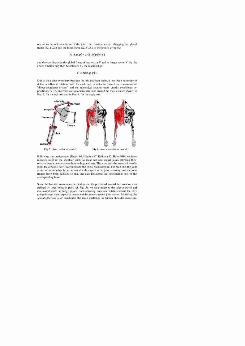
2.2 Musculature
To perform these movements, the upper limb is equipped with at least 22 muscles
actuators, some of which even divide in several bundles attached onto different bones
[Högfors 87]. They can be divided in several groups according to the bones they move
and the DOF they control (cf. Fig. 6). Dvir and Berme noticed that most muscles
acting on the scapula insert close to its medial border [Dvir 78]. This concerns the
levator scapulae, the rhomboids, the middle and the lower parts of the trapezius. These
muscles make the scapula a strong basis for performing the arm movements. The
rotator cuff refers to the group of muscles which covers the humeral head and control
some of its rotations. These are the subscapularis / teres major as opposed to the
infraspinatus / teres minor for controlling the axial rotations, and the supraspinatus /
deltoideus which handle the abduction. The other actuators of the humerus are the

7/18/2019 Maurel Et Al. - 2002 - A Biomechanical Musculoskeletal Model of Human Upper Limb for Dynamic Simulation
http://slidepdf.com/reader/full/maurel-et-al-2002-a-biomechanical-musculoskeletal-model-of-human-upper 4/16
As muscles never work in isolation, natural movements always involve the motions
of all the bones. For a complete analysis, it is necessary to consider the motion of the
mechanism as a whole: almost all investigations on the shoulder girdle motion focus
on the quantification of the scapulo-humeral rhythm during elevation. This rhythm
describes the way in which the humerus elevation is composed of rotations in the
gleno-humeral joint and scapulo-thoracic gliding plane [Hogfors 91]. All the shoulder
bone rotations are involved when for example the arm performs circumduction
movements. Contrary to the shoulder, the forearm movements have been reported as
independent from each other [Youm 79].
Once the anatomy and the biomechanics of the musculoskeletal system have been
observed, qualitative descriptions and classifications can serve as a basis for parameter
definitions. These are necessary for a theoretical mechanical analysis of the system,
which generally lead to its quantitative description. In the following section, wepresent a brief review of the biomechanical models which have been developed for the
human arm.
3 Existing Models
The computer animation of human characters requires more or less the development of
an idealized underlying mechanical models. They generally take the form of a
wireframe hierarchy of one-DOF rotational joints [Huang 94]. Though this approach isgenerally sufficient for most human joints, like the forearm joints for example, when
applied to the shoulder joint, it hardly led to easy (and) realistic animations. An effort
to account for the shoulder rhythm was realized by Badler et al. [Badler 93] who
applied empirical results formulating the clavicular and scapular elevations as
functions of the humeral abduction. However, such relationships only apply for a
given motion, and therefore are not sufficient to realistically describe the general
motion of the shoulder.
In 1980, Engin et al. [Engin 80] presented a research program for determining the
three-dimensional passive resistive joint properties beyond the shoulder complex sinus[Engin 87, Peindl 87]. This research has provided a shoulder model with quantitative
descriptions of the individual joint sinus cones [Engin 89]. Though this is an
improved description of the shoulder, the model does not provide information on the
simultaneous motions of the shoulder bones, unless optimization analysis is applied.
In 1987, another modeling program was initiated by Högfors et al. [Högfors 87] who
d i i i h i di h f i h l d l d i h
7/18/2019 Maurel Et Al. - 2002 - A Biomechanical Musculoskeletal Model of Human Upper Limb for Dynamic Simulation
http://slidepdf.com/reader/full/maurel-et-al-2002-a-biomechanical-musculoskeletal-model-of-human-upper 5/16
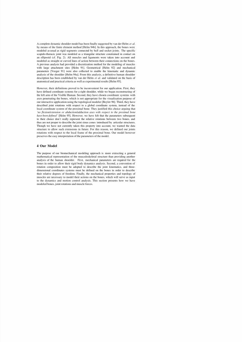
A complete dynamic shoulder model has been finally suggested by van der Helm et al.
by means of the finite element method [Helm 94b]. In this approach, the bones were
modeled as usual as rigid segments connected by ball and socket joints. The specific
scapulo-thoracic joint was modeled as a triangular structure constrained in contact on
an ellipsoid (cf. Fig. 2). All muscles and ligaments were taken into account and
modeled as straight or curved lines of action between their connections on the bones.
A previous analysis had provided a discretization method for the modeling of muscles
with large attachment sites [Helm 91]. Geometrical [Helm 92] and mechanical
parameters [Veeger 91] were also collected to enable the kinematic and dynamic
analysis of the shoulder [Helm 94a]. From this analysis, a definitive human shoulder
description has been established by van der Helm et al. and validated on the basis of
anatomical and practical criteria as well as experimental results [Helm 95].
However, their definitions proved to be inconvenient for our application. First, theyhave defined coordinate systems for a right shoulder, while we began reconstructing of
the left arm of the Visible Human. Second, they have chosen coordinate systems with
axes penetrating the bones, which is not appropriate for the visualization purpose of
our interactive application using the topological modeler [Beylot 96]. Third, they have
described joint rotations with respect to a global coordinate system, instead of the
local coordinate system of the proximal bone. They justified this choice arguing that
‘no flexion/extension or abduction/adduction axes with respect to the proximal bone
have been defined’ [Helm 95]. However, we have felt that the parameters subsequent
to their choice don’t really represent the relative rotations between two bones, andthus are not proper to describe the joint sinus cones introduced by articular structures.
Though we have not currently taken this property into account, we wanted the data
structure to allow such extensions in future. For this reason, we defined our joints
rotations with respect to the local frame of the proximal bone. Our model however
preserves the easy interpretation of the parameters of the model.
4 Our Model
The purpose of our biomechanical modeling approach is more extracting a general
mathematical representation of the musculoskeletal structure than providing another
analysis of the human shoulder. First, mechanical parameters are required for the
bones in order to allow their rigid body dynamics analysis. Second, a convention of
rotation composition must be adopted to describe the joint kinematics, and three-
di i l di b d fi d h b i d d ib
7/18/2019 Maurel Et Al. - 2002 - A Biomechanical Musculoskeletal Model of Human Upper Limb for Dynamic Simulation
http://slidepdf.com/reader/full/maurel-et-al-2002-a-biomechanical-musculoskeletal-model-of-human-upper 6/16
4.1 Bones mechanical properties
The left arm model provided by the reconstruction procedure has been obtained in the
form of seven polygonal bones defined in their own local geometrical frames. These
frames are arbitrarily defined at the reconstruction stage with no specific anatomical
criteria. At that stage, neither hierarchy nor structural dependency relationships exist
among the bones: each one is referred to the global reference frame of the scene by the
way of its 4x4 transfer matrix. Mechanical dependencies are further introduced with the
definitions of the joints mechanics. In our case, all bones have been reconstructed in
the same coordinate system (O0,X0,Y0,Z0) defined in Table 4. Thus, all geometrical
frames are identical to the global reference frame, and every transfer matrix is identity.
In order to allow the rigid body dynamics analysis, we have made the usual
assumption of undeformable bones, and we have assigned to them mechanical
properties, i.e. mass, inertial frame and inertia matrix.
Considering their reduced sizes and motions as well as muscular environments, we
assume that clavicle and scapula have negligible inertia with respect to their
somewhat quasi-static movements. Furthermore, since the inertia properties apply to
the segments accounting for their surrounding flesh, not only for the bones, we
assume that the inertia of humerus, ulna and radius may be approximated to those of
equivalent homogeneous cylinders. With these assumptions, the centers of mass, the
inertial frames and inertia matrix of the segments have been approximated to those of
the corresponding cylinders. Data from Veeger et al. [Veeger 91] for segmentsmechanical modeling are provided in Table 1. Inertial frames are defined in Table 4.
Since for cylinders the transverse axes are indifferent, we choose them arbitrarily.
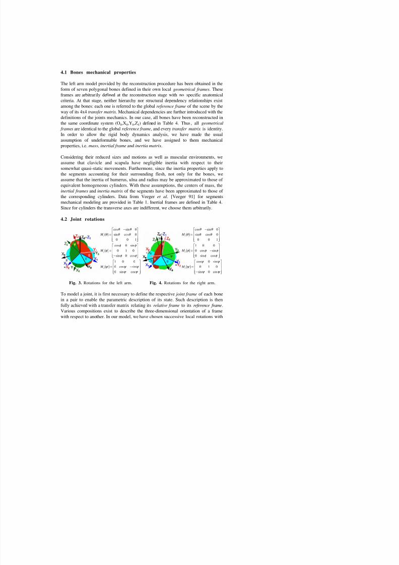
4.2 Joint rotations
M
M
M
z
y
x
θ
θ θ
θ θ
φ φ φ
φ φ
ψ ψ ψ
ψ ψ
( ) =
−
( ) =
−
( ) = −
cos sin
sin cos
cos sin
sin cos
cos sin
sin cos
0
0
0 0 1
00 1 0
0
1 0 0
0
0
M
M
M
z
x
y
θ
θ θ
θ θ
φ φ φ
φ φ
ψ
ψ ψ
ψ ψ
( ) =
−
( ) = −
( ) =
−
cos sin
sin cos
cos sin
sin cos
cos sin
sin cos
0
0
0 0 1
1 0 00
0
0
0 1 0
0
7/18/2019 Maurel Et Al. - 2002 - A Biomechanical Musculoskeletal Model of Human Upper Limb for Dynamic Simulation
http://slidepdf.com/reader/full/maurel-et-al-2002-a-biomechanical-musculoskeletal-model-of-human-upper 7/16
respect to the reference frame of the joint: the rotation matrix changing the global
frame (X0,Y0,Z0) into the local frame (X3,Y3,Z3) of the joint is given by:
M M M M θ ϕ ψ θ ϕ ψ , ,( ) = ( ) ( ) ( )
and the coordinates in the global frame of any vector V and its image vector V' by the
above rotation may then be obtained by the relationship:
′ = ( )V M V θ ϕ ψ , , .
Due to the planar symmetry between the left and right sides, it has been necessary to
define a different rotation order for each one, in order to respect the convention of
"direct coordinate system" and the anatomical rotation order usually considered by
practitioners. The intermediate successive rotations around the local axis are shown inFig. 3. for the left arm and in Fig. 4. for the right arm.
Fig.5. Arm skeleton model. Fig.6. Arm musculature model.
Following our predecessors [Engin 80, Högfors 87, Raikova 92, Helm 94b], we have
modeled most of the shoulder joints as ideal ball and socket joints allowing their
relative bone to rotate about three orthogonal axis. This concerns the sterno-clavicular
joint, the acromio-clavicular joint and the gleno-humeral joint. For each one, the joint
center of rotation has been estimated with respect to the joint anatomy, and the joint
7/18/2019 Maurel Et Al. - 2002 - A Biomechanical Musculoskeletal Model of Human Upper Limb for Dynamic Simulation
http://slidepdf.com/reader/full/maurel-et-al-2002-a-biomechanical-musculoskeletal-model-of-human-upper 8/16
Since the shoulder girdle is a closed kinematic chain, the orientation of the scapula is
doubly defined with respect to the thorax as well as with respect to the clavicle. As it
is usually described with respect to the clavicle, we choose to define the scapular
orientation by the acromio-clavicular joint rotation, and following van der Helm’s
finite element model [Helm 94b], we modeled the scapulo-thoracic joint as a
constraint in contact of the scapula on the thorax approximated by an ellipsoid (cf.
Fig. 7). For an easier description, instead of Cartesian coordinates, we used spherical
coordinates to define the position of the contact on the ellipsoid.
4.3 Joint frames
Fig. 7. shows the joint frames as we have modeled with the topological modeler on
the 3D Visible Human arm model. For most joints, the center has been positioned on
the corresponding anatomical joint center. For convenient use of the topologicalmodeling features, we have chosen our coordinate system to be visible in such a way
that each one can be deduced from the proximal one simply by few permutations and
ordered rotations about the axes. Table 4 summarizes the definitions for our coordinate
systems. Table 5 illustrates the relative positions of each joint frames with respect to
the resting position in which the Visible Human arm has been reconstructed, and
provides the corresponding minimum, maximum and resting values for the rotations
[Kapandji 80].
The acromio-clavicular joint local frame has been defined as recommended by van derHelm and Pronk [Helm 95] in accounting for the palpable scapular bony landmarks of
the scapula, but in such a way that the axes point outside of the bone. As the scapulo-
thoracic constraint has never been defined anatomically, we followed van der Helm’s
finite element approach [Helm 94b] in modeling the thorax with an ellipsoid.
However, contrary to his choice, we estimated the fit better with an ellipsoid bent
backwards with respect to the frontal plane, and thus introduced a backward rotation
between the thorax frame and the global coordinate system (cf. Table 5.6). This is
however no major change on the description of the scapulo-thoracic contact since no
specific parameters exist for it. The description of the contact was found to be easierin terms of spherical coordinates than of Cartesian ones.
4.4 Muscle force
Concerning muscle force modeling, there are basically two methods: the straight line
h hi h h i i d i i f l li d b S i

7/18/2019 Maurel Et Al. - 2002 - A Biomechanical Musculoskeletal Model of Human Upper Limb for Dynamic Simulation
http://slidepdf.com/reader/full/maurel-et-al-2002-a-biomechanical-musculoskeletal-model-of-human-upper 9/16
This approximation is not always valid from anatomical and mechanical points of
view [Zuylen 88]. In our model, we have chosen the intermediate segment-line
approach to represent the muscles lines of action while preserving the anatomical
topological information [Beylot 96].
Fig. 7. Joint frames modeling. Fig. 8. Action lines topology.
In practice, some muscles have very broad attachments while some others divide in
several bundles attached onto different bones. These may be modeled in dividing the
muscles into several lines of action. The choice of the lines must be made on the
basis of anatomical as well as mechanical considerations [Högfors 87]. It was
observed that small changes in the directions or points of application of the forces canhave large effects on the resulting moment vectors. For this purpose, van der Helm et
al. have developed a method to determine the number of muscle force vectors, capable
of representing the mechanical effect of muscles with large attachment sites,
accounting for the form and size of the attachments as well as for the distribution of
the fibers in the muscle [Helm 91]. However, their results implied to model most of
the shoulder muscles with no less than 6 force vectors, which seems to us far too

7/18/2019 Maurel Et Al. - 2002 - A Biomechanical Musculoskeletal Model of Human Upper Limb for Dynamic Simulation
http://slidepdf.com/reader/full/maurel-et-al-2002-a-biomechanical-musculoskeletal-model-of-human-upper 10/16
The topology is needed to compute the direction of the muscle force, which changes
with the motion of the bones. The PCSA is a parameter useful for estimating the
maximal force that the muscle or the bundle can bear [Helm 91]. Fig. 8 shows the
muscular topology as we interactively with the topological modeler [Beylot 96].
Table 3 provides the coordinates of the attachments of the lines of action in
(O0,X0,Y0,Z0). Besides this, Table 2 provides the muscles mass and PCSA parameterswhich are needed for the finite element computation of the deformation [Veeger 91].
5 Interactive Topological Modeling
The theoretical biomechanical model of human upper limb presented here has been
applied to the modeling of the 3D reconstructed left arm of the Visible Human. For
this purpose, we have implemented a topological data structure, and developed an
elaborate modeling tool, in order to allow its interactive editing with the parameters of
the model [Beylot 96]. Details of the procedure are presented hereafter.
5.1 Reconstruction and modeling tools
The first phase of modeling involves 3D surface reconstruction of the desired organs
(e.g., bones for the skeleton). We use imaging data from the Visible Human Data
(VHD) which is part of the Visible Human Project started by the National Library of
Medicine, USA. The reconstruction process may be divided into four steps: thepreprocessing consisting of image filtering and resolution reduction, labeling using
snakes for semi-automatic delineation of each organ of interest in the cross-sectional
images, 3D reconstruction to join the cross-sectional contours, and postprocessing
including matching of reconstruction from different sources (CT, MRI...) [Beylot 96].
In a second phase, we have designed an object-oriented data structure where each
anatomical element is represented by a class which encompasses its physical,
geometrical and mechanical attributes. This data structure contains models for bones,
joints, ligaments, skin, and muscle lines of action. The 3D interactive topologicalmodeler has then been developed to allow the editing of the data base with structural,
topological and mechanical information. The modeler provides extensive 3D
visualization and direct interaction and manipulation. The users can specify the
kinematic parameters (angular limits) of the joints, the dynamic parameters like
inertia matrix of the bones, and the lines of action and force generating parameters of
h l I h f ll i i ill h di i f h j i f

7/18/2019 Maurel Et Al. - 2002 - A Biomechanical Musculoskeletal Model of Human Upper Limb for Dynamic Simulation
http://slidepdf.com/reader/full/maurel-et-al-2002-a-biomechanical-musculoskeletal-model-of-human-upper 11/16
5.2 Joint topological modeling
First we have approximately placed the bone coordinate systems as defined by van der
Helm [Helm 95], after adjustment for the left arm, as a basis to build our frames. A
feature of the topological modeler allows the rigorous alignment of any frame on any
other one and the rigorous relative permutations between its axes. Thus from oneframe, it is possible to obtain any configuration of its axis around the height octants.
We have then created each joint by the successive selection of the reference bone and
the relative bone, and placed its center on the corresponding anatomical joint center.
Then we have adjusted successively the joint frames for the sterno-clavicular , acromio-
clavicular and gleno-humeral joints: for each one, the joint reference and local frames
have been defined respectively on the basis of the local frame of the previous joint and
on the basis of those we call van der Helm’s frames. While the frame orientations are
being defined, the angular parameters of the model are automatically extracted from the
rotation matrix and saved in the data base. Thus, the complete ‘rest’ state of the
Visible Human is directly available. In annex are summarized the definitions for bones
(Table 1), muscles (Table 2&3), coordinate systems and hierarchical transfer matrix
(Table 4), and joint parameters minimal, maximal, and current values (Table 5).
6 Conclusion
The computer simulation of human complex joints requires the development of
elaborate biomechanical models underlying the geometrical objects representing theanatomical components. In this paper, we have provided the complete model of
human upper limb that we have applied to the 3D left human arm, reconstructed from
the Visible Human imaging Dataset. This analysis is necessary to allow the
development of the data structures, topological modeling tools and dynamic
simulation procedures on concrete basis. In our approach, we have achieved a balance
between accuracy and simplicity for preserving the biomechanical validity, as well as
the the feasibility of the project. However, the model and data structure have been
designed to allow further improvements, such as a finer discretization of the muscles
or the replacement of the current kinematic joints by dynamic joints, which is of interest for joint dislocation simulation. The next step is the motion control of the
upper limb.
Acknowledgments. We are grateful to the other partners of the CHARM project: Ecole
des Mines de Nantes (EMN), University de las Islas Baleares (UIB), University of Karlsruhe
(UK) and Technical University of Lisbon (IST) for the instructive collaboration we have
7/18/2019 Maurel Et Al. - 2002 - A Biomechanical Musculoskeletal Model of Human Upper Limb for Dynamic Simulation
http://slidepdf.com/reader/full/maurel-et-al-2002-a-biomechanical-musculoskeletal-model-of-human-upper 12/16
[Chao 78] E.Y. Chao, B.F. Morrey, (1978), "Three-dimensional rotation of the
elbow", J. Biomechanics, 11, 57-73
[CHARM 93] CHARM, (1993), Esprit Project 9036, Part I : "Technical Annex"
[Dvir 78] Z. Dvir, N. Berme, (1978), "The shoulder complex in elevation of the
arm: a mechanism approach", J. Biomechanics, 11, 219-225.
[Engin 80] A.E. Engin, (1980) "On the biomechanics of the shoulder complex", J. Biomechanics , 13, 575-590
[Engin 87] A.E. Engin, R.D. Peindl, (1987) "On the biomechanics of human
shoulder complex - I. Kinematics for determination of the shoulder
complex sinus", J. Biomechanics , 20, 2, 103-117
[Engin 89a] A.E. Engin, S.T. Tumer, (1989) "Three-dimensional kinematic modeling
of the human shoulder complex - I. Physical model and determination of
joint sinus cones", J. biomech. Engng ., 111, 107-112
[Engin 89b] A.E. Engin, S.T. Tumer, (1989) "Three-dimensional kinematic modeling
of the human shoulder complex - II. Mathematical modeling and
solution via optimization" - J. biomech. Engng ., 111, 113-121[Grant 91] Grant’s Atlas of Anatomy - Ninft Edition - ed. Anne M.R. Agnus -
Baltimore: Williams & Wilkins
[Hainaut 76] K. Hainaut, (1976), "Introduction à la biomécanique", Paris: Maloine
[Helm 91] F.C.T. Van der Helm, R. Veenbaas, (1991), "Modeling the mechanical
effect of muscles with large attachment sites: Application to the
shoulder mechanism", J. Biomechanics, 27, 1151-1163
[Helm 92] F.C.T. Van der Helm, H.E.J. Veeger, G.M. Pronk, L.V.H. Van der
Woude, R.H. Rozendal, (1992), "Geometry parameters for
musculoskeletal modelling of the shoulder system", J. Biomechanics ,25, 2, pp. 129-144, 1992
[Helm 94a] F.C.T. Van der Helm, (1994), "Analysis of the kinematic and dynamic
behavior of the shoulder mechanism", J. Biomechanics, 27, 527-550
[Helm 94b] F.C.T. Van der Helm, (1994), "A finite element musculoskeletal model
of the shoulder mechanism", J. Biomechanics, 27, 551-569
[Helm 95] F.C.T. van der Helm, G.M. Pronk, (1995) "Three-dimensional recording
and description of motions of the shoulder mechanism", J. biomech.
Engng. 117, 27-40
[Högfors 87] C. Högfors, G. Sigholm, P. Herberts, (1987) "Biomechanical model of
the human shoulder - I. Elements" - J. Biomechanics , 20, 157-166[Högfors 91] C. Högfors, B. Peterson, G. Sigholm, P. Herberts, (1991)
"Biomechanical model of the human shoulder joint", J. Biomechanics ,
24, 699-709
[Huang 94] Z. Huang, N. Magnenat Thalmann, D. Thalmann, (1994) "Interactive
human motion control using a closed form of direct and inverse
dynamics" Pacific Graphic Conference Proceedings Beijing 94

7/18/2019 Maurel Et Al. - 2002 - A Biomechanical Musculoskeletal Model of Human Upper Limb for Dynamic Simulation
http://slidepdf.com/reader/full/maurel-et-al-2002-a-biomechanical-musculoskeletal-model-of-human-upper 13/16
[Kapandji 80] I.A. Kapandji, (1980) Physiologie articulaire - Tome 1: Membre
supérieur - Maloine S.A. Editeur
[Karlsson 92] D. Karlsson, B. Peterson, (1992) "Towards a model for force predictions
in the human shoulder", - J. Biomechanics, 25, 189-199
[Peindl 87] R.D. Peindl, A.E. Engin, (1987) "On the biomechanics of human
shoulder complex - II. Passive resistive properties beyond the shouldercomplex sinus", J. Biomechanics , 20, 2, 119-134
[Pronk 91] G. Pronk, (1991) The Shoulder Girdle, Analysed and Modelled
Kinematically, Diss., Technische Universiteit Delft
[Raikova 92] R. Raikova, (1992) "A general approach for modelling and
mathematical investigation of the human upper limb", J. Biomechanics,
25, 857-867
[Seireg 89] R.A. Seireg, Arvikar, (1989) Biomechanical Analysis of the
Musculoskeletal Structure for Medicine and Sports , Himisphere
Publishing Corporation.
[Thomson 64] Arthur Thomson, A Handbook of Anatomy for Art Students - DoverPublications Inc.1964 - Oxford University Press 1896.
[Veeger 91] H.E.J. Veeger, F.C.T. Van der Helm, L.H.V. Van der Woude, G.M.
Pronk, R.H. Rozendal, (1991) "Inertia and muscle contraction
parameters for musculoskeletal modelling of the shoulder mechanism",
J. Biomechanics , 24, 7, 615-629
[Wood 89] J.E. Wood, S. G. Meek, S. C. Jacobsen, (1989) "Quantitation of human
shoulder anatomy for prosthetic arm control - I. Surface modelling", J.
Biomechanics , 22, 3, 273-292.
[Youm 79] Y. Youm, R.F. Cryer, K. Thambyrajah, A.E. Flatt, B.L. Sprague, (1979)"Biomechanical analysis of forearm pronation-supinat ion and elbow
flexion-extension", J. Biomechanics, 12, 245-255
[Zuylen 88] E.J. van Zuylen, A. van Velzen, J.J. Denier van der Gon, (1988) "A
biomechanical model for flexion torques of human arm muscles as a
function of elbow angle", J. Biomechanics, 21, 183-190
Appendix
Cylindrical inertia :
I
A F E
F B D
E D C
=
− −
− −
− −
C mr
D E F
A Bmr mh
=
= = =
= = +
2
2 2
2
0
4 12
segment
Parameters
humeral forearm
+ hand
ulnar radial
(k ) 1 81 1 6 0 8 0 8
z: long axis
r: radius
h: height
Muscle Mass (g) Muscle Mass (g)
Biceps 114.1 Teres minor 28.3
Triceps 99.7 Infraspin. 109.8
C b 30 6 S i 36 2

7/18/2019 Maurel Et Al. - 2002 - A Biomechanical Musculoskeletal Model of Human Upper Limb for Dynamic Simulation
http://slidepdf.com/reader/full/maurel-et-al-2002-a-biomechanical-musculoskeletal-model-of-human-upper 14/16
Lines / PCSA Coordinates (X, Y, Z) Bone
Anconeus
2.50
O(601, 285, -588)
I(596, 289, -611)
Hum.
Ulna
Biceps
long
3.21
O(487, 246, -291)
G1(499, 215, -297)G2(506, 213, -317)
G3(518, 227, -355)
Scap.
Hum.Hum.
Hum.
Biceps short
3.08
O(472, 210, -302) Scap.
Biceps I(565, 254, -622) Radius
Brachialis
8.40
O(552, 257, -467)
I(572, 278, -620)
Hum.
Ulna
Brachiorad.
4.70
O(585, 279, -532)
I(490, 117, -752)
Hum.
RadiusCoracobrach.
2.51
O(476, 211, -301)
I(535, 249, -423)
Scap.
Hum.
Deltoideus
anterior
8.63
O(468, 231, -272)
G1(493, 217, -319)
G2(526, 229, -376)
Clav.
Hum.
Hum.
Deltoideus
lateral
8.63
O(511, 222, -273)
G1(524, 207, -303)
G2(526, 210, -318)
Scap.
Hum.
Hum.
Delt. post.8.63 O(484, 288, -274)G(540, 250, -376) Scap.Hum.
Deltoideus I(547, 241, -405) Hum.
Infraspinatus
9.51
O(449, 315, -355)
G(532, 243, -300)
I(528, 216, -297)
Scap.
Hum.
Hum.
Latis. upper
2.83
O(341, 321, -431)
G(440, 336, -419)
VT07
Scap.
Latis. medial
2.83
O(342, 325, -558)
G(420, 326, -484)
VT11
R09
Latissimus
dorsi
lower
2.83
O(344, 299, -692)
G1(440, 310, -590)
G2(461, 299, -551)
I(512, 231, -348)
V3
R11
R10
Hum.
Levator
2.82
O(354, 228, -203)
I(402, 283, -278)
VC3
Scap.
Lines / PCSA Coordinates (X, Y, Z) Bone
Pronator teres
2.00
O(559, 303, -573)
I(531, 182, -686)
Hum.
Radius
Rhomb. upper
3.14
O(334, 265, -256)
I(402, 311, -288)
VC6
Scap.Rhomb. lower
3.14
O(332, 302, -332)
I(419, 335, -363)
VT03
Scap.
Serratus ant.
upper
7.00
O(458, 159, -457)
G(461, 239, -384)
I(407, 317, -302)
R05
R04
Scap.
Serratus ant.
lower
7.00
O(478, 173, -561)
G(466, 260, -453)
I(421, 330, -362)
R08
R07
Scap.
Subclavius2.00
O(399, 207, -326)I(458, 234, -278)
R01Clav.
Subscapularis
13.51
O(445, 312, -341)
I(491, 223, -319)
Scap.
Hum.
Supinator
3.00
O(600, 288, -569)
G1(598, 299, -611)
G2(584, 251, -623)
G3(565, 230, -635)
I(547, 219, -654)
Hum.
Ulna
Radius
Radius
Radius
Supraspinatus
5.21
O(461, 270, -301)
G(504, 233, -284)
I(511, 207, -297)
Scap.
Hum.
Hum.
Teres major
10.20
O(469, 310, -391)
I(506, 237, -339)
Scap.
Hum.
Teres minor
2.92
O(475, 305, -373)
I(535, 235, -311)
Scap.
Hum.
Trap. upper
5.30
O(330, 248, -185)
I(498, 236, -259)
VC2
Clav.
Trap. medial
5.30
O(331, 312, -333)
I(408, 324, -303)
VT03
Scap.
Trapezius
lower
5.30
O(340, 330, -507)
G(427, 334, -363)
I(472, 294, -276)
VT09
Scap.
Scap.
Triceps long
2.30
O(498, 261, -331) Scap.

7/18/2019 Maurel Et Al. - 2002 - A Biomechanical Musculoskeletal Model of Human Upper Limb for Dynamic Simulation
http://slidepdf.com/reader/full/maurel-et-al-2002-a-biomechanical-musculoskeletal-model-of-human-upper 15/16
Absolute Reference SC reference frame GH reference frame
O01st right higher voxel OSC center, on sternum OGH center, on scapula
X0 ⊥ to FP, forward XSC ⊥ to FP, forward ZGH ⊥ to scap. plane, forw.
Y0 ⊥ to SP, forward YSC ⊥ to SP, to the left XGH from Trigonum Spinae
ST reference frame SC local frame GH local frameOT center of ellipsoid OSC center, on clavicle OGH center, on humerus
YT ⊥ to SP, to the left YC / / to (OSCOAC), to OAC ZH ⊥ to hfp, forward
ZT long axis, upwards XC ⊥ to YC, in clp, forward YH long humeral axis, upw.
AC reference frame UH reference frame UR reference frame
OAC center, on clavicle OUH center, on humerus OUR center, on ulna
XAC / / to (OSCOAC), to OAC ZUH / / to (OUHOHR), outward ZUR / / to (OHROUR), to hand
YAC ⊥ to XAC, in clp, backw. XUH ⊥ to (OGHOUHOHR), forw. YUR rest, ⊥ (OHROUROR), inw.
AC local frame UH local frame UR local frameOAC center, on scapula OUH center, on ulna OUR center, on radius
YS ⊥ to scap. plane backw. ZU / / to (OUHOHR), outward ZR / / to (OHROUR), to hand
XS from Trigonum Spinae XU ⊥ to (OUHOHROUR), forw. YR ⊥ to (OHROUROR), inw.
Humerus inertial frame Ulna inertial frame Radius inertial frame
OHI center of humerus OUI center of ulna ORI center of radius
ZHI ⊥ to hfp, forward ZUI / / to (OUHOHR), outward ZRI / / to (OHROUR), to hand
YHI long humeral axis, upw. XUI ⊥ to (OUHOHROUR), forw. YRI ⊥ to (OHROUROR), inw.
(OTXTYTZT)
in (O0X0Y0Z0)
(OSCXSCYSCZSC)
in (O0X0Y0Z0)
(OACXACYACZAC)
in (OSCXCYCZC)
(OGHXGHYGHZGH)
in (OACXSYSZS)
(OSTXSYSZS)
in (OACXSYSZS)
0 1 0 337.2 0 1 0 356.1 0 -1 0 0 1 0 0 2.71 1 0 0 -122.26
-0.996 0 0.089 2 33.3 -1 0 0 180.2 1 0 0 165.4 0 0 -1 -3.41 0 1 0 -17.02
0.089 0 0.996 -483.9 0 0 1 -335.2 0 0 1 0 0 1 0 -42.3 0 0 1 -90.43
0 0 0 1 0 0 0 1 0 0 0 1 0 0 0 1 0 0 0 1
(OUHXUHYUHZUH)
in (OGHXHYHZH)
(OURXURYURZUR)
in (OUHXUYUZU)
(OUIXUIYUIZUI)
in (OUHXUYUZU)
0 0 1 -4.95 0 1 0 0.195 -0.978 -0.187 -0.0872 -12.26
0 -1 0 -293.6 -0.115 0 0.993 241.8 0.0519 0.185 -0.981 120.3
1 0 0 7.99 0.993 0 0.105 46.13 0.2001 -0.965 -0.172 23.59
0 0 0 1 0 0 0 1 0 0 0 1
(ORIXRIYRIZRI) (OHIXHIYHIZHI) ⊥ : normal to / / : parallel to ...

7/18/2019 Maurel Et Al. - 2002 - A Biomechanical Musculoskeletal Model of Human Upper Limb for Dynamic Simulation
http://slidepdf.com/reader/full/maurel-et-al-2002-a-biomechanical-musculoskeletal-model-of-human-upper 16/16
5.1 Sterno-Clavicular joint
angle θC ϕC ψ C
axis ZC XC YC
min - 5º +0º -30º
max +30º +40º +10ºres t +22º +24º + 0º
5.6 Scapulo-thoracic joint
a,b,c( ) ellipsoid parameters
θ OST ,ϕ OST
( ) spherical coordinates
xOST = a.cosϕ OST
cosθ ϕ ST
yOST = b.cos
ϕ OST sin
θ ϕ ST zOST
= c.sinϕ OST
Table 5. Joints Rotations.
5.2 Acromio-Clavicular joint
angle θS ϕS ψ S
axis ZS XS YS
m in -68º -10 º -1 0º
max -60º +0º +0ºrest -65º -7º -6º
parameter a b c
axis XT YT ZT
value +120 +150 +210
angle θOst ϕOst
min +120º +20º
max +140º +40º
rest +130º +29º
5.3 Gleno-Humeral joint
angle θH ϕH ψ H
axis ZH XH YH
min -40º -100º -90º
max +100º +50º +90ºrest -13º +3º +0º
5.4 Ulno-Humeral joint
angle θU min max rest
axis ZU -140º +0º -57º
5.5 Ulno-radial joint
angle θR m in max rest
axis ZR +0º +180º +100º