Mauna Kea - East Asian Observatory
47
Mauna Kea
Transcript of Mauna Kea - East Asian Observatory

Mauna Kea

Per Friberg Head of Instrumentation JCMT• Master degree in Engineering from Chalmers University of
Technology (Sweden) - Theoretical Physics/Computers (1977).
• Ph.D .Onsala Space Observatory 1983. Spectroscopy of organic molecules in space.
• Post Doc. FCRAO, University of Massachusetts (Amherst)
• Researcher at Onsala Observatory.
• Staff member at the SEST telescope in Chile.
• Joined the JCMT staff in 1990.
• Head of Instrumentation JCMT since 1999.

JCMT Telescope and Instrumentation
January 2015

Main Instruments:• SCUBA-2 - 10.000 pixel bolometer camera
operating simultaneously at 450 and 850 µm
• HARP - 16 pixel 350 GHz band heterodyne array receiver
• RxA - Single pixel 230 GHz band heterodyne receiver (mmVLBI)
• ACSIS - 32 channel spectrometer used with the heterodyne inst.

Additional Instruments• RxW - 660 GHz band heterodyne receiver. Out of
service. Competes with SCUBA-2
• POL-2 - Polarimeter for the full field of SCUBA-2. Under commissioning. Operates at 450 and 850 µm
• FTS-2 - Fourier Transform Spectrometer for ~1/8 the SCUBA-2 field of view. Under commissioning. Operates at 450 and 850 µm
• Rover - Heterodyne Polarimeter. Partly Commissioned. Operates at the 230 and 350 GHz band.
Helper Instruments• Water Vapor Monitor. Looks at 183 GHz water line and
measure atmospheric water vapor content. Used to and calculate the opacity (extinction). Critical for SCUBA-2 calibration.
• Access to SMA phase monitor data. Used for the submm seeing.
• Holography System (H3): 80/160 GHz source and receiver for measuring the dish surface. Used to maintain the surface accuracy.
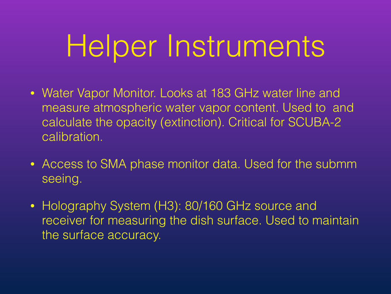
• Gortex membrane protects telescope when the building is open.
• Makes daytime observations possible - JCMT can observe the Sun
• Drawback losses, added noise and polarization.

• Cassegrain design - 10’ FOV
• Focal Stations: Cass. cabin, Left & Right Nasmyth
• Chopping Secondary
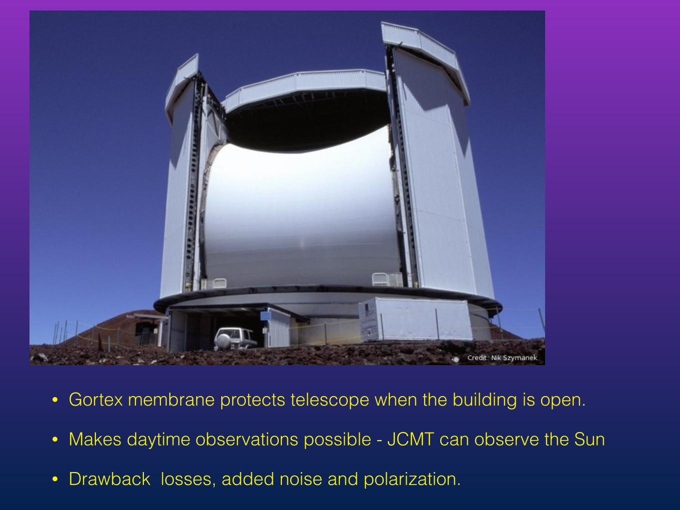
SCUBA-2 tertiary mirror with reflection of the secondary mirror and support.
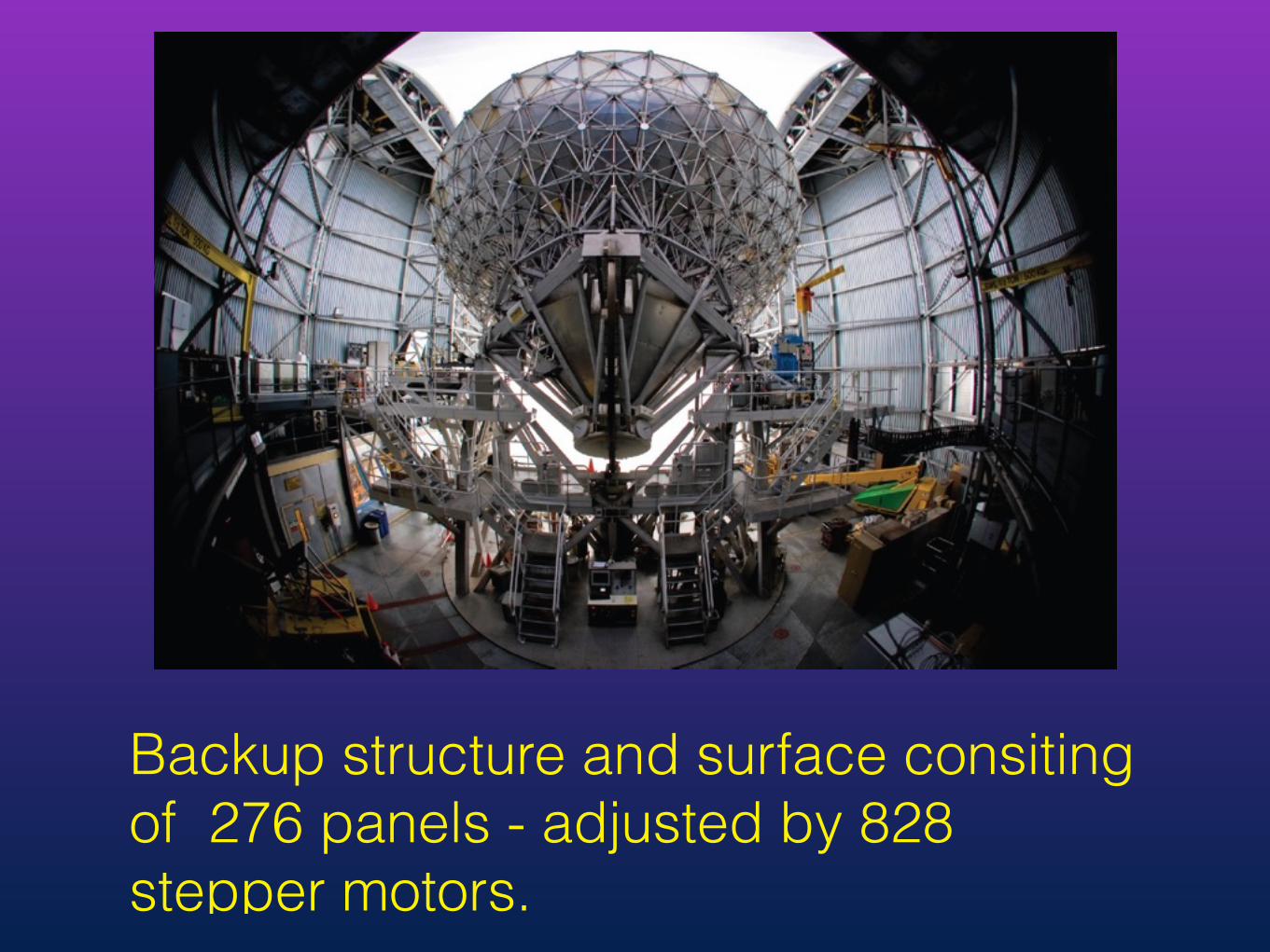
Backup structure and surface consiting of 276 panels - adjusted by 828 stepper motors.

160 GHz surface map from December 18th. 2014 Measured rms 23.4 micron.
Panels and shadows from secondary as it’s support visible. Map takes 2 hours and is obtained during night time due to
thermal issues.

• Beam maps at 450 micron
• Core beam Gaussian HPBW 7.9” with a lower pedestal HPBW 25”
• Ring ~ 183” diameter at low level

Moon Scan with 350 GHz receiver. Sensitive to more extended beam contributions.

Daytime decrease in efficiency • Cause - thermal distortions • Also due to opacity variations and poor seeing

225 GHz Opacity
wvm - red CSO 225 -green
350µm-blue
Seeing SMA phase
monitor
Seeing needed for 450 < 1” for 850 < 2”
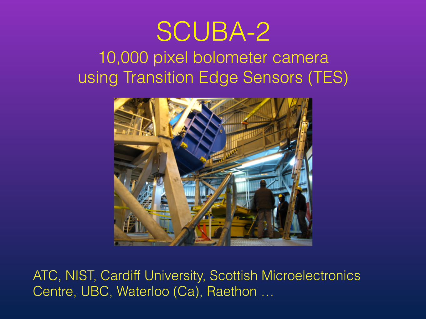
SCUBA-2 10,000 pixel bolometer camera
using Transition Edge Sensors (TES)
ATC, NIST, Cardiff University, Scottish Microelectronics Centre, UBC, Waterloo (Ca), Raethon …
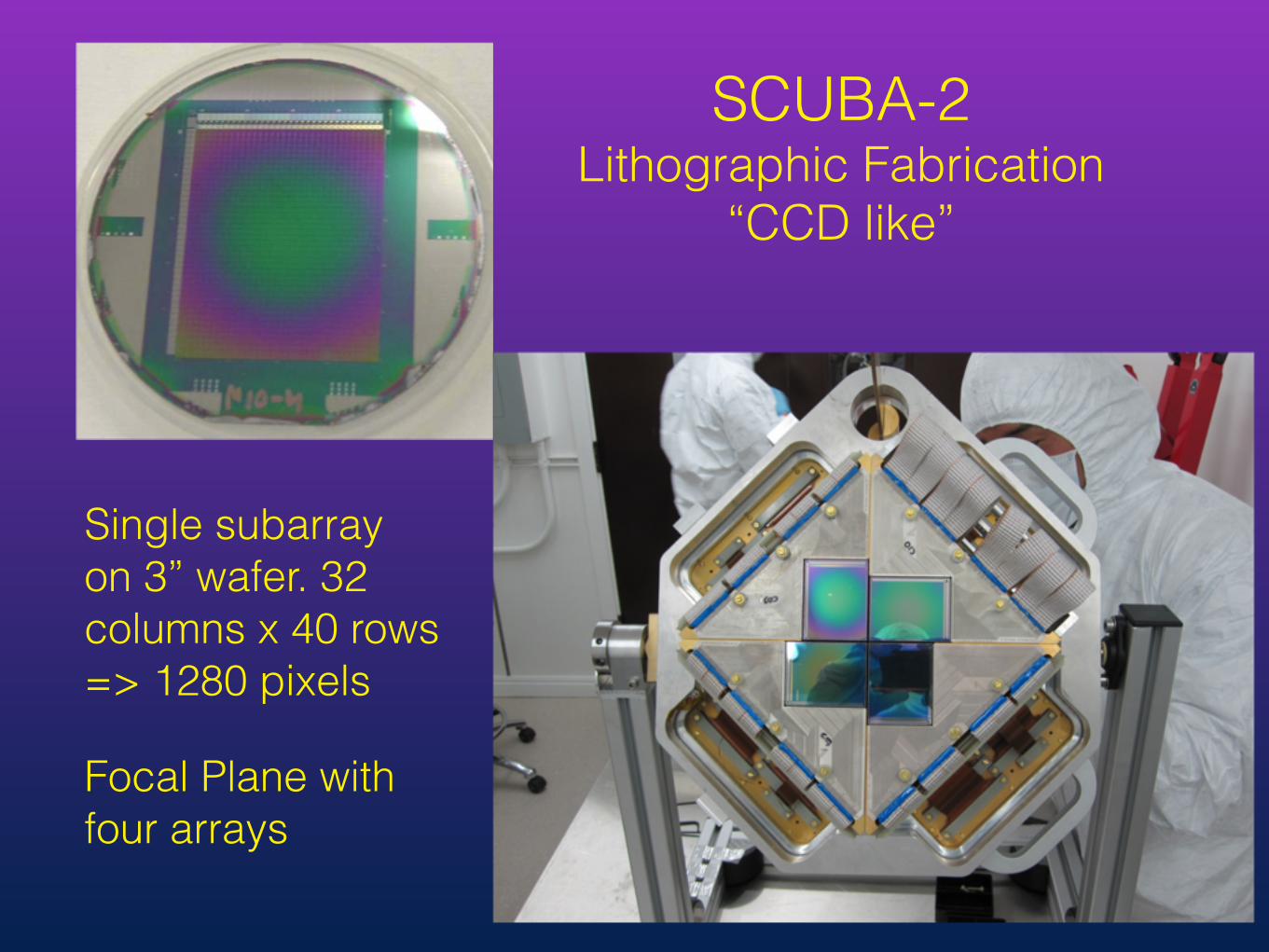
Single subarray on 3” wafer. 32 columns x 40 rows => 1280 pixels
Focal Plane with four arrays
SCUBA-2 Lithographic Fabrication
“CCD like”
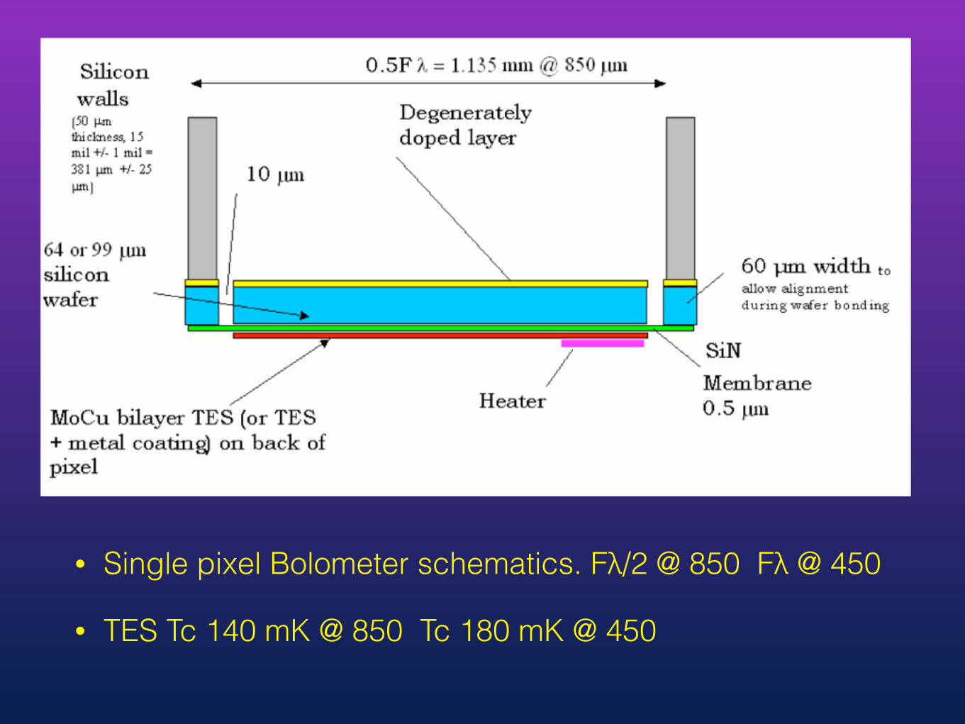
• Single pixel Bolometer schematics. Fλ/2 @ 850 Fλ @ 450
• TES Tc 140 mK @ 850 Tc 180 mK @ 450

Simplified schematics of SQUID multiplexer with 3 rows 3 columns
Colors different wafers - detector (blue), multiplexer (green), yellow (SQUID amp)
Only one bias and one heater connection per array.

• Layout of one SQUID readout cell
• One cell ~ 1x1 mm behind each bolometer

• SCUBA-2 optics

SCUBA-2 fridge - we can keep SCUBA-2 cold for over a year.
Dilution fridge base temperature ~ 50 mK

Array responsitivity or flat filed @ 450 micron
Flat fielding by ramping the heater.
The flat field ramps calibrates the data and is used to iden-tify noisy and non-linear bolometers for removal.
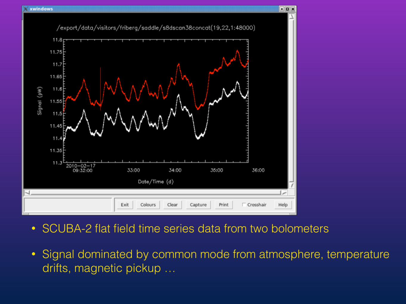
• SCUBA-2 flat field time series data from two bolometers
• Signal dominated by common mode from atmosphere, temperature drifts, magnetic pickup …
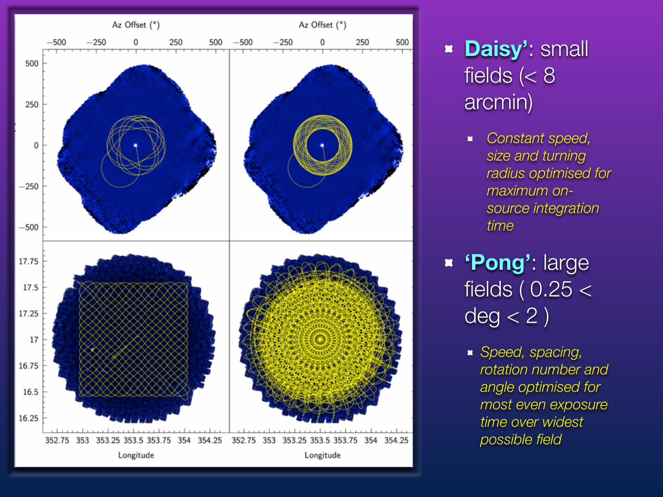
Daisy’: small fields (< 8 arcmin)
Constant speed, size and turning radius optimised for maximum on-source integration time
‘Pong’: large fields ( 0.25 < deg < 2 )
Speed, spacing, rotation number and angle optimised for most even exposure time over widest possible field

Wavelength Yield NEP (W√s) Responsivity (A/W)
850μm (dark) 3430 9.3 x 10⁻¹⁷ 1.4 x 10⁶
850μm (sky) 3339 1.48 x 10⁻¹⁶ 1.4 x 10⁶
450μm (dark) 3540 2.36 x 10⁻¹⁶ 6.1 x 10⁵
450μm (sky) 3434 3.4 x 10⁻¹⁶ 6.1 x 10⁵
SCUBA-2 NEP

HARP 16 Pixel 350 GHz
Band Array
• Trx 100-150 K, IF bandwidth 2 GHz • SSB mode with cold load termination. • no Dual SideBand possible • Automatic Tuning

• Mixer block with integrated feed horns
• Refocusing mirrors
• LO injection (not shown) by mylar
• Pixels separated by 30” on the sky (2x HPBW)
HARP Mixers

K-mirror rotates array 14.3 degrees relative the scan direction
Raster mapping (OTF) with HARP: 350 GHz Band

230 GHz Band RxA
• Tuning ranger 211-272 GHz (gap around 252 GHz)
• Trx 50-150 K
• Auto tuning & Dual sideband operation - no SSB

ACSIS Correlator
• 32 channels
• 250 or 1000 MHz bandwidth
• 2 GHz samplers
• Temperature stabilized
• Fast - 0.1 s dump time for large scale mapping


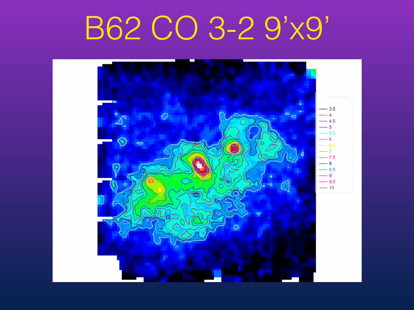
B62 CO 3-2 9’x9’

Subaru Hα
UKIRT WFCAM JHK composite

• Out of operation, can be repaired and reinstated if there is interest
• Need good weather
• Partial manual tuning - cumbersome and time consuming to tune
• Trx 500-700 K tuning range 630-700 GHz
• Dual mixer per frequency band/ dual Frequency bands.
• Single Sideband and Dual Sideband operation. In SSB mode the unwanted sideband is dump on cold load
RxW 660 GHz
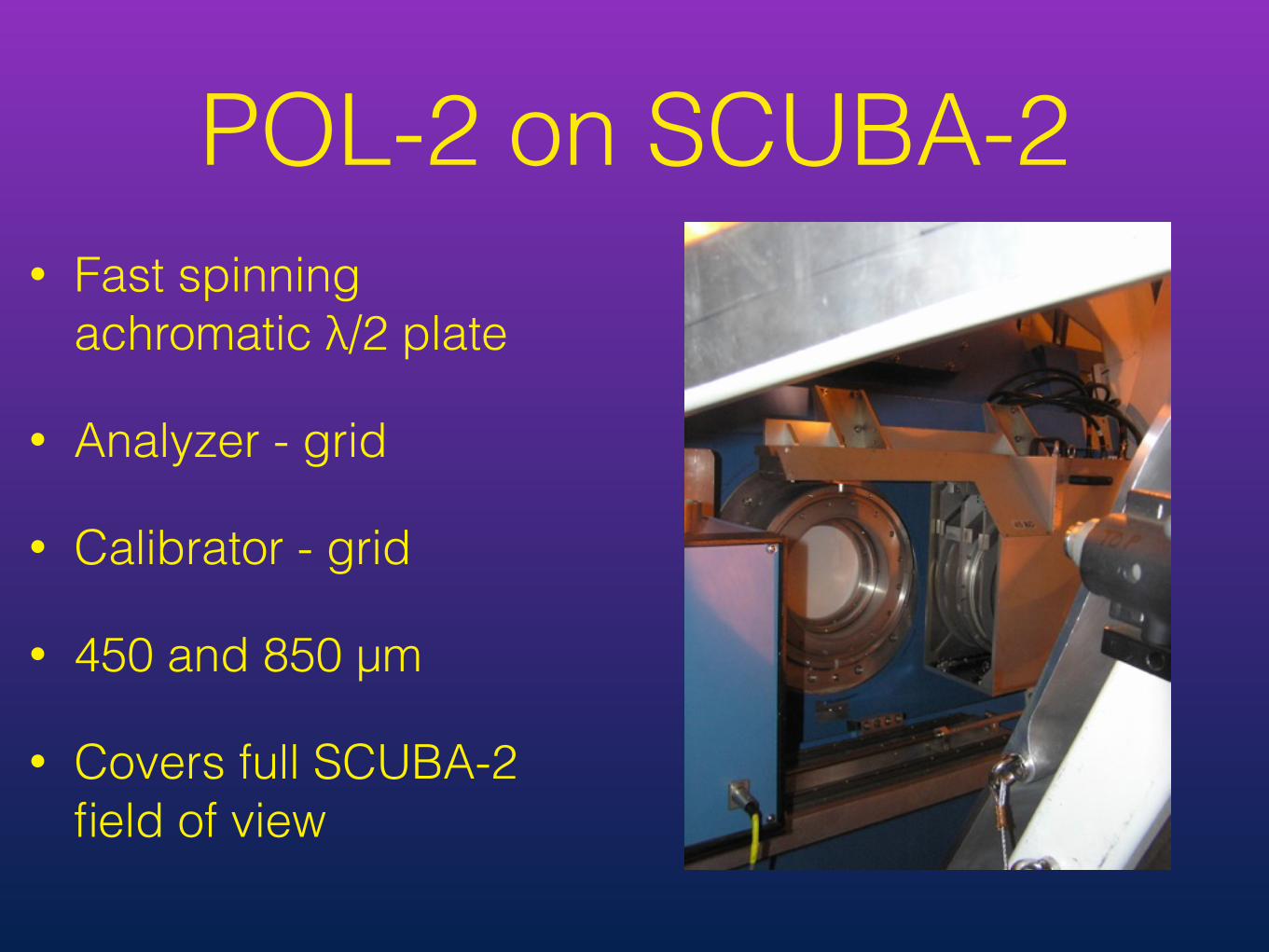
POL-2 on SCUBA-2• Fast spinning
achromatic λ/2 plate
• Analyzer - grid
• Calibrator - grid
• 450 and 850 µm
• Covers full SCUBA-2 field of view
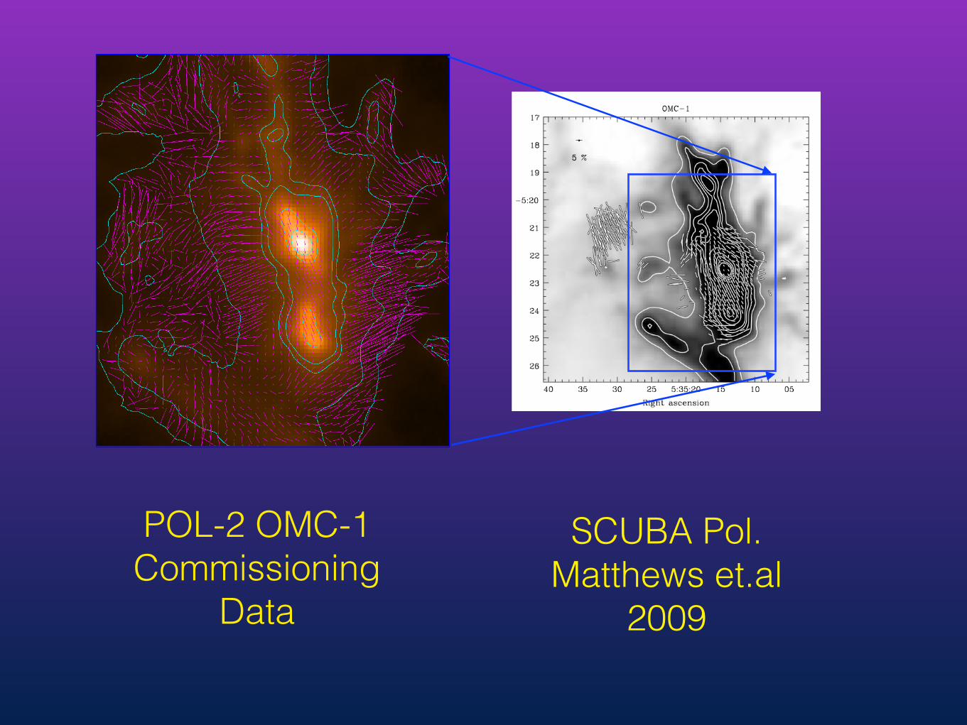
SCUBA Pol. Matthews et.al
2009
POL-2 OMC-1 Commissioning
Data

Needs work on• Wave plate reflections
(loading variation with 2 x spin rate)
• Data defects
• Observing method (sky background removal)
• Data reduction
• IP model/removal
Flat fielded time series data from POL-2 (few bolo-meters)

FTS-2 Inserted in the SCUBA-2 optical path in on the Nasmyth platform.
R ~10-5000
Two main modes: SED (low resolution) @ High ReSolution (HRS)
• Field of view ~ 5 arcmin^2 in low resolution SED mode • Field of view ~ 1 arcmin^2 in HRS mode

FTS-2
Issues: Dynamical range
Linearity Flux jumps
port imbalance
Spectra map of Jupiter
Interferograms
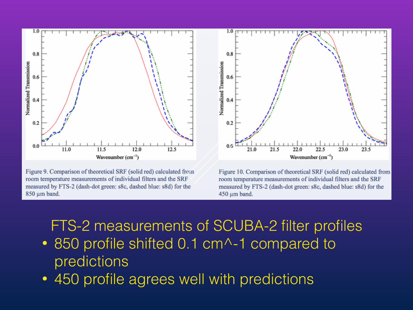
FTS-2 measurements of SCUBA-2 filter profiles • 850 profile shifted 0.1 cm^-1 compared to
predictions • 450 profile agrees well with predictions

• Achromatic λ/2 plate - 230 & 350 GHz band, Also used for the VLBI λ/4 plate.
• Using the 0.1 s dump time of ACSIS to read out spectra fast.
• Tested at 230 GHz but not 350 GHz
ROVER Heterodyne polarimeter
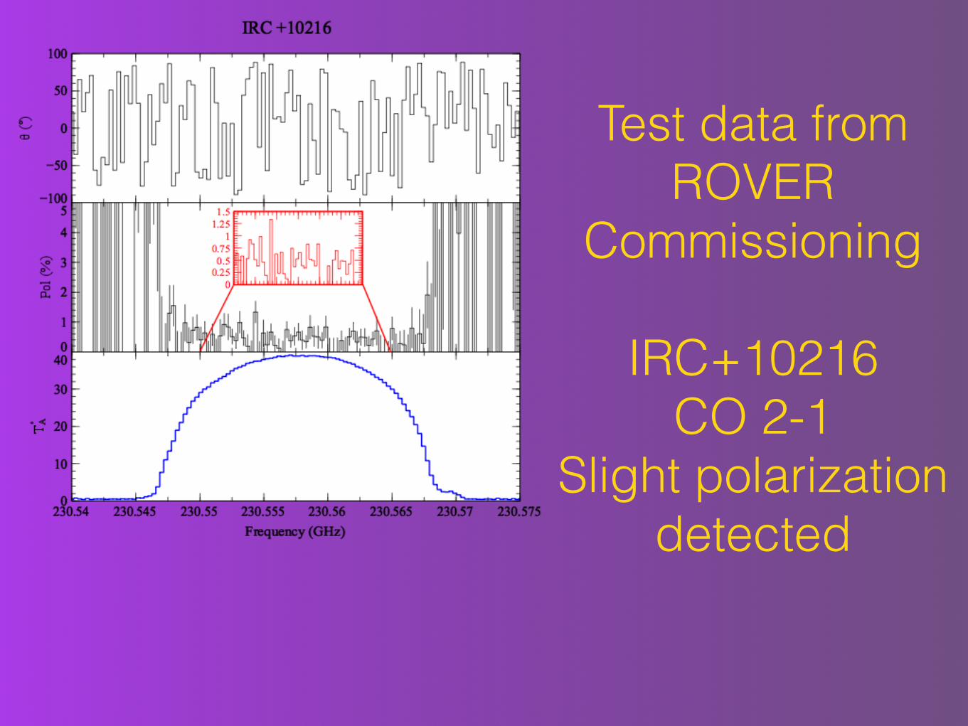
Test data from ROVER
Commissioning
IRC+10216 CO 2-1
Slight polarization detected

• SCUBA-2 Filter witdhs & atmosphere
• The 692 GHz CO line one edge of 450 filter

Heterodyne Bands JCMT
Different names than ALMA & SMA