Matthew Chapman Caesar
171
Identity-based routing Matthew Chapman Caesar Electrical Engineering and Computer Sciences University of California at Berkeley Technical Report No. UCB/EECS-2007-114 http://www.eecs.berkeley.edu/Pubs/TechRpts/2007/EECS-2007-114.html September 3, 2007
Transcript of Matthew Chapman Caesar

Identity-based routing
Matthew Chapman Caesar
Electrical Engineering and Computer SciencesUniversity of California at Berkeley
Technical Report No. UCB/EECS-2007-114
http://www.eecs.berkeley.edu/Pubs/TechRpts/2007/EECS-2007-114.html
September 3, 2007

Copyright © 2007, by the author(s).All rights reserved.
Permission to make digital or hard copies of all or part of this work forpersonal or classroom use is granted without fee provided that copies arenot made or distributed for profit or commercial advantage and that copiesbear this notice and the full citation on the first page. To copy otherwise, torepublish, to post on servers or to redistribute to lists, requires prior specificpermission.

Identity-based Routing
by
Matthew C. Caesar
B.S. (University of California Davis) 2000M.S. (University of California Berkeley) 2004
A dissertation submitted in partial satisfaction of therequirements for the degree of
Doctor of Philosophy
in
Computer Science
in the
GRADUATE DIVISIONof the
UNIVERSITY OF CALIFORNIA, BERKELEY
Committee in charge:Professor Randy H. Katz, Chair
Professor Ion StoicaProfessor Charles Stone
Fall 2007

The dissertation of Matthew C. Caesar is approved:
Chair Date
Date
Date
University of California, Berkeley
Fall 2007

Identity-based Routing
Copyright 2007
by
Matthew C. Caesar
Abstract
Identity-based Routing
by
Matthew C. Caesar
Doctor of Philosophy in Computer Science
University of California, Berkeley
Professor Randy H. Katz, Chair
Routing today scales by assigning addresses that depend on the host’s topological location
in the network. Topology-based addressing improves scalability, since adjacent addresses may be
aggregated into blocks and advertised as a single unit. However, if hosts move, or the network
topology changes, these addresses must change. This poses two problems. First, in ad-hoc networks
and sensornets, the topology is so fluid that topology-based addressing doesn’t work. There has been
a decades-long search for scalable routing algorithms for these networks with no solution in sight.
Second, the use of topology-based addressing in the Internet complicates mobility, access control,
and multihoming.
Identity-based addressing, where addresses refer only to the identity of the host but not
its location, would solve these problems, but would pose severe challenges for scalability. This
thesis presents the first scalable routing algorithm for identity-based addresses. Implementation
results from a sensornet deployment and simulations demonstrate the protocol outperforms several
traditional wireless routing algorithms. This thesis also describes extensions to scale the protocol to
Internet-size topologies and support several common ISP-level routing policies.

Professor Randy H. KatzDissertation Committee Chair

.

2
Contents
Contents 2
List of Figures 5
List of Tables 7
Acknowledgements 8
1 Introduction 101.1 How networks work today . . . . . . . . . . . . . . . . . . . . . . . . . . . . . . 12
1.1.1 Routing in a single ISP . . . . . . . . . . . . . . . . . . . . . . . . . . . . 131.1.2 Inter-ISP routing . . . . . . . . . . . . . . . . . . . . . . . . . . . . . . . 141.1.3 The Domain Name System (DNS) . . . . . . . . . . . . . . . . . . . . . . 16
1.2 Problems with today’s networks . . . . . . . . . . . . . . . . . . . . . . . . . . . 171.3 The need for identity-based routing . . . . . . . . . . . . . . . . . . . . . . . . . . 211.4 Thesis contributions and structure . . . . . . . . . . . . . . . . . . . . . . . . . . 23
1.4.1 Phase 1: Routing on an abstract graph . . . . . . . . . . . . . . . . . . . . 241.4.2 Phase 2: Application to wireless networks . . . . . . . . . . . . . . . . . . 251.4.3 Phase 3: Application to Internet routing . . . . . . . . . . . . . . . . . . . 261.4.4 Summary and thesis roadmap . . . . . . . . . . . . . . . . . . . . . . . . 27
2 Background and related work 282.1 Assigning labels to nodes . . . . . . . . . . . . . . . . . . . . . . . . . . . . . . . 29
2.1.1 What differentiates our work . . . . . . . . . . . . . . . . . . . . . . . . . 342.2 Network resolution among labels . . . . . . . . . . . . . . . . . . . . . . . . . . . 34
2.2.1 What differentiates our work . . . . . . . . . . . . . . . . . . . . . . . . . 362.3 Locator resolution to paths . . . . . . . . . . . . . . . . . . . . . . . . . . . . . . 37
2.3.1 Wireless routing protocols . . . . . . . . . . . . . . . . . . . . . . . . . . 382.3.2 Distributed hash tables . . . . . . . . . . . . . . . . . . . . . . . . . . . . 402.3.3 Internet routing . . . . . . . . . . . . . . . . . . . . . . . . . . . . . . . . 422.3.4 What differentiates our work . . . . . . . . . . . . . . . . . . . . . . . . . 45
2.4 Summary and thesis roadmap . . . . . . . . . . . . . . . . . . . . . . . . . . . . . 46

3 Routing on an abstract graph 483.1 State maintained at each node . . . . . . . . . . . . . . . . . . . . . . . . . . . . . 483.2 Packet forwarding . . . . . . . . . . . . . . . . . . . . . . . . . . . . . . . . . . . 513.3 Maintenance . . . . . . . . . . . . . . . . . . . . . . . . . . . . . . . . . . . . . . 55
3.3.1 Join protocol . . . . . . . . . . . . . . . . . . . . . . . . . . . . . . . . . 563.3.2 Path maintenance . . . . . . . . . . . . . . . . . . . . . . . . . . . . . . . 593.3.3 Ring maintenance . . . . . . . . . . . . . . . . . . . . . . . . . . . . . . . 613.3.4 Examples . . . . . . . . . . . . . . . . . . . . . . . . . . . . . . . . . . . 66
3.4 Analysis . . . . . . . . . . . . . . . . . . . . . . . . . . . . . . . . . . . . . . . . 673.4.1 Path-consistency . . . . . . . . . . . . . . . . . . . . . . . . . . . . . . . 683.4.2 Ring consistency . . . . . . . . . . . . . . . . . . . . . . . . . . . . . . . 69
3.5 Summary and thesis roadmap . . . . . . . . . . . . . . . . . . . . . . . . . . . . . 72
4 Application to wireless networks 744.1 Introduction . . . . . . . . . . . . . . . . . . . . . . . . . . . . . . . . . . . . . . 744.2 Wireless extensions . . . . . . . . . . . . . . . . . . . . . . . . . . . . . . . . . . 764.3 Sensornet implementation . . . . . . . . . . . . . . . . . . . . . . . . . . . . . . 77
4.3.1 Experimental setup . . . . . . . . . . . . . . . . . . . . . . . . . . . . . . 774.3.2 Results from deployment . . . . . . . . . . . . . . . . . . . . . . . . . . . 80
4.4 802.11b simulations . . . . . . . . . . . . . . . . . . . . . . . . . . . . . . . . . . 834.4.1 Large-scale simulations . . . . . . . . . . . . . . . . . . . . . . . . . . . 894.4.2 Cross-validation . . . . . . . . . . . . . . . . . . . . . . . . . . . . . . . 92
4.5 Summary and thesis roadmap . . . . . . . . . . . . . . . . . . . . . . . . . . . . . 94
5 Application to the Internet 965.1 Introduction . . . . . . . . . . . . . . . . . . . . . . . . . . . . . . . . . . . . . . 965.2 Overview . . . . . . . . . . . . . . . . . . . . . . . . . . . . . . . . . . . . . . . 98
5.2.1 Preliminaries . . . . . . . . . . . . . . . . . . . . . . . . . . . . . . . . . 995.2.2 Intradomain . . . . . . . . . . . . . . . . . . . . . . . . . . . . . . . . . . 1025.2.3 Interdomain . . . . . . . . . . . . . . . . . . . . . . . . . . . . . . . . . . 103
5.3 Intradomain . . . . . . . . . . . . . . . . . . . . . . . . . . . . . . . . . . . . . . 1075.3.1 Host Join . . . . . . . . . . . . . . . . . . . . . . . . . . . . . . . . . . . 1075.3.2 Failure . . . . . . . . . . . . . . . . . . . . . . . . . . . . . . . . . . . . 1085.3.3 Packet forwarding . . . . . . . . . . . . . . . . . . . . . . . . . . . . . . 110
5.4 Interdomain . . . . . . . . . . . . . . . . . . . . . . . . . . . . . . . . . . . . . . 1115.4.1 Basic design . . . . . . . . . . . . . . . . . . . . . . . . . . . . . . . . . 1125.4.2 Handling policies . . . . . . . . . . . . . . . . . . . . . . . . . . . . . . . 118
5.5 Additional routing issues . . . . . . . . . . . . . . . . . . . . . . . . . . . . . . . 1205.5.1 Routing Control . . . . . . . . . . . . . . . . . . . . . . . . . . . . . . . 1205.5.2 Enhanced Delivery Services . . . . . . . . . . . . . . . . . . . . . . . . . 1215.5.3 Security . . . . . . . . . . . . . . . . . . . . . . . . . . . . . . . . . . . . 122
5.6 Evaluation . . . . . . . . . . . . . . . . . . . . . . . . . . . . . . . . . . . . . . . 1235.6.1 Methodology . . . . . . . . . . . . . . . . . . . . . . . . . . . . . . . . . 1235.6.2 Intradomain . . . . . . . . . . . . . . . . . . . . . . . . . . . . . . . . . . 1275.6.3 Interdomain . . . . . . . . . . . . . . . . . . . . . . . . . . . . . . . . . . 129

5.6.4 Distributed implementation . . . . . . . . . . . . . . . . . . . . . . . . . 1345.6.5 Summary of results . . . . . . . . . . . . . . . . . . . . . . . . . . . . . . 136
5.7 Summary and thesis roadmap . . . . . . . . . . . . . . . . . . . . . . . . . . . . . 137
6 Conclusions and Future Work 1396.1 Contributions . . . . . . . . . . . . . . . . . . . . . . . . . . . . . . . . . . . . . 1396.2 Key results . . . . . . . . . . . . . . . . . . . . . . . . . . . . . . . . . . . . . . 1406.3 Future work . . . . . . . . . . . . . . . . . . . . . . . . . . . . . . . . . . . . . . 141
6.3.1 Thesis summary . . . . . . . . . . . . . . . . . . . . . . . . . . . . . . . 144
Bibliography 146

5
List of Figures
1.1 Example: how Internet routing works today. . . . . . . . . . . . . . . . . . . . . 121.2 An example of a hierarchical network. . . . . . . . . . . . . . . . . . . . . . . . . 141.3 Example: how DNS works. . . . . . . . . . . . . . . . . . . . . . . . . . . . . . 161.4 Example problems in today’s Internet. . . . . . . . . . . . . . . . . . . . . . . . . 18
3.1 Virtual and network-level topologies. . . . . . . . . . . . . . . . . . . . . . . . . 493.2 Forwarding table. . . . . . . . . . . . . . . . . . . . . . . . . . . . . . . . . . . . 503.3 Example: forwarding a packet. . . . . . . . . . . . . . . . . . . . . . . . . . . . . 513.4 Example: forwarding a packet using the shortcutting optimization. . . . . . . . . 513.5 Example: a new node joins the network. . . . . . . . . . . . . . . . . . . . . . . . 563.6 Example: path-vector maintenance. . . . . . . . . . . . . . . . . . . . . . . . . . 593.7 Example: local repair. . . . . . . . . . . . . . . . . . . . . . . . . . . . . . . . . 613.8 Examples: ring misconvergence. . . . . . . . . . . . . . . . . . . . . . . . . . . . 623.9 Ring with nodes numbered 0 through N. . . . . . . . . . . . . . . . . . . . . . . . 71
4.1 Sensornet testbed deployment. . . . . . . . . . . . . . . . . . . . . . . . . . . . . 774.2 mica2dot sensornet motes. . . . . . . . . . . . . . . . . . . . . . . . . . . . . . . 784.3 Sensornet experiments: effect of congestion . . . . . . . . . . . . . . . . . . . . . 804.4 Sensornet experiments: effect of failures . . . . . . . . . . . . . . . . . . . . . . 814.5 Sensornet experiments: stretch penalty . . . . . . . . . . . . . . . . . . . . . . . 814.6 NS-2 Experiments: Effect of network size, 10% communicating nodes . . . . . . 844.7 NS-2 Experiments: Effect of network size, 20% communicating nodes . . . . . . 844.8 NS-2 Experiments: control overhead as a function of network size and density . . 854.9 NS-2 Experiments: breakdown of control overhead by message type, sparse network 854.10 NS-2 Experiments: breakdown of control overhead by message type, dense network 864.11 NS-2 Experiments: comparison with traditional protocols, 50 nodes . . . . . . . . 864.12 NS-2 Experiments: comparison with traditional protocols, 100 nodes . . . . . . . 874.13 NS-2 Experiments: comparison with traditional protocols, 200 nodes . . . . . . . 874.14 NS-2 Experiments: stretch penalty, dense network . . . . . . . . . . . . . . . . . 884.15 NS-2 Experiments: stretch penalty . . . . . . . . . . . . . . . . . . . . . . . . . . 884.16 NS-2 Experiments: stretch penalty, sparse network . . . . . . . . . . . . . . . . . 894.17 Larger scale experiments: control overhead as a function of network size. . . . . . 904.18 Larger scale experiments: data packet stretch penalty. . . . . . . . . . . . . . . . 90

4.19 Larger scale experiments: CDF of data packet stretch penalty, 100 nodes. . . . . . 914.20 Larger scale experiments: CDF of data packet stretch penalty, 1000 nodes. . . . . 914.21 Cross-validation experiments: CDF of simulator stretch. . . . . . . . . . . . . . . 934.22 Cross-validation experiments: CDF of implementation latency and hopcount. . . . 934.23 Cross-validation experiments: control overhead scaling trends. . . . . . . . . . . . 94
5.1 A host with ida has pointers to an internal successor, Succ(ida), and an externalsuccessor, Ext succ(ida). . . . . . . . . . . . . . . . . . . . . . . . . . . . . . . . 102
5.2 Merging rings . . . . . . . . . . . . . . . . . . . . . . . . . . . . . . . . . . . . . 1125.3 Routing state for virtual node with identifier 8. . . . . . . . . . . . . . . . . . . . . 1135.4 Conversion rules for (a) peering (b) multihoming and backup. . . . . . . . . . . . . 1185.5 Cumulative overhead to construct the network. . . . . . . . . . . . . . . . . . . . 1245.6 CDF of overhead per node join. . . . . . . . . . . . . . . . . . . . . . . . . . . . 1245.7 Join latency. . . . . . . . . . . . . . . . . . . . . . . . . . . . . . . . . . . . . . 1245.8 Effect of pointer cache size on stretch. . . . . . . . . . . . . . . . . . . . . . . . . 1255.9 Load balance, compared with shortest-path routing (OSPF). . . . . . . . . . . . . 1255.10 Memory used per router. . . . . . . . . . . . . . . . . . . . . . . . . . . . . . . . 1255.11 Convergence overhead from Point of Presence (PoP) failures . . . . . . . . . . . . 1295.12 Comparison of joining strategies. . . . . . . . . . . . . . . . . . . . . . . . . . . . 1305.13 Stretch. . . . . . . . . . . . . . . . . . . . . . . . . . . . . . . . . . . . . . . . . 1305.14 Effect of pointer caching. . . . . . . . . . . . . . . . . . . . . . . . . . . . . . . . 1305.15 Distributed simulator, control overhead. . . . . . . . . . . . . . . . . . . . . . . . 1345.16 Distributed simulator, data packet stretch. . . . . . . . . . . . . . . . . . . . . . . 1345.17 Planetlab deployment, data packet latency. . . . . . . . . . . . . . . . . . . . . . 136
7
List of Tables
4.1 Number of lines of code for each of the implementations . . . . . . . . . . . . . . 83

Acknowledgments
I am grateful for the feedback and advice from the people I worked with at Berkeley. I was
very fortunate to get Randy as an advisor, working with him has been an amazing experience. His
focused and precise approach to mentoring, and his dead-on advice at every turn contributed vastly
to this thesis and my growth as a researcher. I have also benefited very much from Ion Stoica’s
mentoring. He guided me with solid expertise and the sharp intellect of a true visionary. I also
owe a great debt to Scott Shenker for his support and encouragement, and his uncanny ability to
synthesize problems and give just the right feedback. Randy, Ion, and Scott continually astounded
me with their thoughtfulness, razor-sharp intellect, and fun-loving nature. They will be role models
for me for years to come.
At Berkeley I found myself surrounded by an amazing group of students. I would like
to thank the students from 473 Soda Hall (Sharad Agarwal, Chen-Nee Chuah, Weidong Cui, Yin
Li, Sridhar Machiraju, Morley Mao, George Porter, Jimmy Shih, Helen Wang) and the rest of
the systems group (Byung-Gon Chun, Prabal Dutta, Cheng Tien Ee, Rodrigo Fonseca, Brighten
Godfrey, Dilip Joseph, Jayanthkumar Kannan, Karthik Lakshminarayanan, Ananth Rao, Mukund
Seshadri, Sonesh Surana, Fang Yu, Shelley Zhuang), and too many others to mention, for letting me
pester them with questions, fun conversations, and their invaluable feedback over the years. Also,
many thanks to Dilip Joseph for helping me with the filing of this dissertation.
I’ve been lucky to work with several extraordinary people outside of Berkeley. I want to
thank Jennifer Rexford for mentoring me. I am grateful for the numerous phone meetings, her ten-
page long in-depth responses to my emails, and her patience in teaching me how to build systems. I
was also very lucky to work with Kobus van der Merwe and Aman Shaikh from AT&T, and Miguel
Castro and Ant Rowstron from MSR.
I am grateful to the National Science Foundation, the American Society for Engineering
education, AT&T Labs, and Microsoft Research for their financial support. I also appreciate the
funding provided through Berkeley via the UC MICRO program.

I thank my parents, my sisters, and the rest of my family for being pillars of support over
the years. I am indebted to them for their understanding and patience when it was most required.
Above all, I would like to thank my future wife, Serena, for her optimism, her constant support and
encouragement, and her unwavering faith in me. She was a beacon of hope throughout my Ph.D.
and without her this thesis would not have been possible.
10
Chapter 1
Introduction
Referencing objects based on their name, or identity, has long been the accepted method
of managing data in computing systems. For example, file systems identify files based on a filename,
and databases find objects by their attributes. Binding objects to a fixed identity provides a very
powerful and intuitive semantics which makes it easy to build and use computer systems. Often this
binding takes place through a resolution mechanism, where the identity is mapped to an intermediate
location-based representation, for example an address on a disk or in memory.
The designers of the Internet long ago recognized that some form of persistent identity
was necessary for networks to be useful. However, doing this scalably was considered to be a chal-
lenging problem. To circumvent the problem, the Internet’s designers abandoned fixed identity in
favor of addressing. Addresses are numeric values assigned to hosts as a function of their location in
the network, and bear no relation to host identity. Annotating hosts with network location allows us
to build very scalable networks, since the address may function as a highly compact representation
of the route to a particular host in the network.
However, for most networked applications today, the notion of an “address” is meaning-
less. Applications instead typically refer to servers or resources in the network by their identity,
which is a much more simple and intuitive way to do things. To deal with this conundrum, the
Domain Name Service (DNS) [105] was deployed to map between addresses and identity. Instead

of resolving addresses to identifiers on a per-packet or per-request basis, this mapping was done on
a per-connection granularity to improve scalability.
This design choice has drastically complicated the Internet’s design. Performing resolu-
tion on a per-connection basis greatly complicates mobility and network configuration. The use of
DNS incurs the cost of building and maintaining an additional system, and DNS is fraught with its
own scaling challenges and introduces fate sharing issues [113, 17]. Moreover, DNS does not solve
the address management problem. Internet addresses are misconfigured by operators on a regular
basis, leading to several high-profile Internet-wide disruptions [14, 103]. Moreover, drastic scaling
problems arise when addresses don’t conform to the network topology. The demands of an increas-
ingly rich interconnection environment coupled with the desire not to introduce NATs as an integral
part of the architecture has led network operators to abandon the CIDR model of highly-aggregated
addresses tightly bound to network location. This has led to instability and routing table size in-
creasing faster than Moore’s law, leading to exponentially increasing network hardware costs and
continual upgrades. Moreover, since host identities aren’t visible within networks, access controls
and policies become hard to write and keep up to date.
This dissertation focuses on how to build scalable address-free networks. We give the first
scalable network-layer routing protocol that operates directly on fixed identities. We refer to this
protocol as Identity-Based Routing (IBR). The protocol is amenable to analysis, and we prove cor-
rect operation in the presence of fail-stop failures, and establish polynomial bounds on convergence
time and control overhead. To demonstrate its practicality, we perform several implementations of
the protocol in the context of the large-scale Internet and highly dynamic wireless networks. Be-
fore diving in to the technical design, we start this chapter by giving some background on how
networks work today (Section 1.1) and the problems they face (Section 1.2). We then overview the
problem we’re trying to solve (Section 1.3), and our approach to finding and evaluating a solution
(Section 1.4).

1.1 How networks work today
The Internet is formed of a collection of Internet Service Providers (ISPs), each of which
operates a network that provides connectivity between customers and other ISPs. Each host in the
Internet is annotated with an IP address denoting is topological location. Each ISP network runs a
routing protocol, which performs a distributed computation to determine paths for packets to follow
from the current router to an address. To forward a packet to an address, the host appends the
destination address to the packet, and intermediate routers look up the shortest path to the router
connected to that address. ISPs also jointly run the Border Gateway Protocol (BGP) [144] to build
routes that traverse multiple ISPs. In order to map from human-readable names to addresses, the
Internet also runs the Domain Name Service (DNS) [105], which consists of a hierarchical collection
of name resolution servers.
Figure 1.1: Example: how Internet routing works today.
Figure 1.1 shows an example. First suppose the network operator for UC Berkeley’s cam-
pus network wishes to make web pages available to download on the web server www.cs.berkeley.edu.
First, the network operator for ISP Z registers the (www.cs.berkeley.edu, 169.229.60.105) mapping
with DNS, and configures a route to 169.229.60.105 within Berkeley’s internal network. Next,
suppose a host h with IP address 24.75.0.3 in Level3’s ISP network wishes to download a web
page from www.cs.berkeley.edu. Host h first performs a DNS lookup to determine the IP address
169.229.60.105 corresponding to www.cs.berkeley.edu. Then, h constructs a data packet contain-

ing a request for the web page, and places IP address 169.229.60.105 in the data packet’s header.
Host h then sends this packet to its upstream router. The router looks up the shortest path towards the
destination address, and forwards the packet to the next hop along that path. This process continues
until the packet reaches the destination.
This simple example skips over many details. For example, we have not yet discussed how
routes to addresses are computed or looked up, how routes may be formed across multiple ISPs, or
how DNS records or new network-level routes are provisioned. The remainder of this Section fills in
these details. Section 1.1.1 describes how routing is done within a single ISP network. Section 1.1.2
describes how several ISPs work together to form inter-domain paths to hosts that exist in a remote
ISP. Section 1.1.3 describes how host addressing works, and the DNS infrastructure used to map
between addresses and persistent names. Later, in Section 2.3.3 we will describe other protocols
and work related to network routing.
1.1.1 Routing in a single ISP
Networks run protocols to allow participating hosts to communicate with each other.
These routing protocols work by storing information about paths used to reach other hosts in the
network. These paths are discovered in a distributed fashion. There are a variety of ways to compute
these paths. For example, there are a class of flooding-based protocols that rely on network-wide
broadcasts to discover paths. One commonly-used flooding-based protocol is link-state. Link-state
works by propagating information about the existence of adjacencies between nodes that may be
used for forwarding. When a node n1 discovers a new link to a neighbor n2, it creates a routing
update packet with the information (n1, n2). When another node n3 receives the update, it inserts
the adjacency into a link-state database. If the link was not already present in the database, n3 dis-
tributes the update to each of its neighbors. When this process completes, the link-state database at
a given node contains a list of all links in the network. To forward packets, a node computes a path
from itself to the destination by traversing the link-state database. Commonly used link-state pro-

tocols in ISP networks include OSPF [108] and IS-IS [18]. Other flooding-based protocols, include
distance-vector [120]-based protocols such as RIP [64, 46], and hybrid protocols such as Cisco’s
EIGRP [181].
However, flooding-based approaches are not scalable to large networks or networks with
high rates of change. They require state proportional to the number of nodes in the network, leading
to large memory requirements. Also, nodes need to process events for every other node in the net-
work, leading to large computation requirements and slowing convergence after events. Hence such
approaches do not work for very large networks like the Internet (300 million hosts) or networks
with high rates of churn like ad-hoc networks, or highly resource constrained environments, like
sensornets. In the next section, we describe how the Internet leverages the notion of hierarchy to
scale to these larger sizes.
1.1.2 Inter-ISP routing
Figure 1.2: An example of a hierarchical network.
The traditional way to build scalable networks is by using a technique called addressing.
The idea behind addressing is to assign numeric identifiers to nodes that represent their location in
the network topology. For example, one common technique is hierarchical addressing, which is
used in the Internet as well as some wireless networks. Hierarchical addressing works as shown

in Figure 1.2. Nodes co-located in the topology are organized into areas. Nodes are then assigned
addresses such that the prefix of the address is equal to the area in which the node resides. Instead
of maintaining state for the entire topology, each node maintains routes to each node within its own
area, and also a route to each external area. When a source in area a1 forwards a packet to a node in
a different area a2, it forwards the packet towards a2. When a node inside a2 receives the packet, it
forwards the packet directly to the destination.
There are two key benefits of addressing. First, unlike node identifiers, addresses may be
aggregated into blocks and then advertised as a single unit. This eliminates the need to advertise ev-
ery node to every other node in the network, improving scalability. Second, unlike node identifiers,
the address conveys information about the location of the destination node. This makes routing
simple, because information about the path to reach a node is embedded in the address.
ISPs in today’s Internet share a global 32-bit address space which are allocated in blocks
called IP prefixes1 . Each IP prefix represents a collection of IP addresses adjacent in the address
space that share a common prefix. An administrative organization known as IANA [184] (operated
by ICANN [185]) is responsible for dividing up the address space into prefixes and doling out pre-
fixes to ISPs. Each ISP then may break up its prefix further into sub-prefixes or subnets. Typically
an ISP will allocate a subnet to each of its internal routers that is upstream of another network or
collection of hosts. Hosts are then assigned an address that is within the prefix of their upstream
router. In the example in Figure 1.1, ISP A was allocated prefix 12.0.0.0/8 from IANA [184]. ISP
A then allocates subnets 12.1.0.0/16 and 12.2.0.0/16 to its customers B and C . Network operators
at ISP B assign access router b prefix 12.1.1.0/24 and host h’s IP address 12.1.1.3. To send a packet
to h, a remote host h2 sends a packet with 12.1.1.3 in the header. Intermediate routers then look
up the longest prefix which contains the address contained in the header, and forward the packet
towards the ISP containing that prefix.1The first generation of IP syntax assigned addresses in a set of classes termed A,B,C. Each class corresponded to a
particular fixed prefix length. Since classful networking can leave gaps in allocation that poorly utilize address space,Classless Inter-Domain Routing (CIDR) was introduced to allow prefixes to be defined at arbitrary lengths. CIDR is thetechnique used today when allocating addresses.

An ISP may then make its internal prefixes globally reachable by advertising them via the
Border Gateway Protocol (BGP). Each ISP runs BGP sessions on peering links between its border
routers and its neighboring ISPs. Upon provisioning a new prefix, border routers are configured to
advertise the new prefix to its neighbors. Upon receipt of a BGP routing advertisement, neighboring
domains propagate the update to their neighbors. In so doing, global reachability to the prefix is
attained. To ensure their internal hosts can reach remote addresses, BGP updates are redistributed
to internal routers. This is typically done by running BGP sessions to internal routers. When BGP is
run internally it is referred to as iBGP. An internal router then computes its forwarding table as the
accumulation of internally-learned routes from the intra-domain routing protocol (e.g. OSPF [108])
as well as externally-learned routes from iBGP.
1.1.3 The Domain Name System (DNS)
Figure 1.3: Example: how DNS works.
Our discussion of the example in Figure 1.1 omitted one crucial detail: the procedure
for h2 to discover the address assigned to h. To address this problem, the Internet assigns Fully
Qualified Domain Names (FQDNs) to hosts and uses the Domain Name Service (DNS) to map
from FQDNs to addresses. DNS consists of a hierarchical system of name servers deployed across
multiple ISPs. FQDNs are assigned from a from a hierarchical space of names. This space is

divided into zones, each of which is controlled by an authoritative DNS name server. For example
(Figure 1.3), to resolve the FQDN www.cs.berkeley.edu, the host first contacts the name server
authoritative for the root of the namespace. That name server returns the IP address of the name
server authoritative for the .edu domain. The host then asks the name server for the .edu domain for
the IP address of the name server authoritative for berkeley.edu. This process continues until the
server authoritative for the full FQDN is reached, which returns the IP address of the Although this
approach seems slow and prone to failure, performance is improved by the use of caching. However,
cached entries can become stale, leading to a tradeoff between delay and consistency. Revisiting the
example in Figure 1.3, if h2 knew h’s FQDN, h2 would use DNS to look up h’s IP address.
DNS is typically used on a per-connection basis. In fact, DNS makes heavy use of
caching, meaning that lookups are performed once for multiple connections. This is done for
efficiency reasons, as performing a DNS lookup for every packet would result in significant in-
efficiencies. Unfortunately, this leads to the several problems mentioned before: DNS state can
become stale, and network-level access controls and policies become difficult. While performing a
DNS lookup for every packet would solve several of these problems, such an approach would not
be tractable, which is one of the reasons why these sacrifices were made in the Internet’s design.
These problems are discussed in more detail in the next section.
1.2 Problems with today’s networks
We start this section with several example challenges that arise in networks that use ad-
dressing to scale. We then proceed to describe the larger space of challenges and touch on some
previous attempts to address them.
Multihoming (Figure 1.4a): Often in computer networks, routers have more than one physical
neighbor. The same is true in the ISP-level Internet graph. In this example, ISP D purchases
service from ISP C . ISP C is assigned prefix 20.0.0.0/8, and assigns its customer D the subnet
20.1.0.0/16. ISP D has a single host h assigned IP address 20.1.7.3. In this case, C only needs to

Figure 1.4: Example problems in today’s Internet.
advertise the single prefix 20.0.0.0/8.
For redundancy purposes, D may purchase a service from a second provider ISP E. When
this happens, E must advertise D’s prefix 20.1.0.0/16 to inform remote hosts they can reach hosts
within that subnet via E.2
In general, the increased levels of multihoming in today’s Internet has led to vastly in-
creased routing table sizes as ISPs need to advertise every prefix that is not contained within their
supernet prefix. Growth in Internet routing tables and churn is exceeding the capabilities of Moore’s
law to keep up, leading to large router cost increases and slowing Internet convergence [98]. More-
over, addresses must be managed and reassigned as the network topology changes over time. The
benefit of identity-based routing is that networks do not have to know about the current assignment
of IP prefixes to routers in order to forward packets. Moreover, operators don’t have to worry about
assigning and managing IP prefixes, since addresses are not necessary when routing directly on
identity.2Since the Internet uses longest-prefix match, C must also advertise the more-specific route to prevent all traffic to D
being sent via E.

Host mobility (Figure 1.4b): Host h resides in ISP F . ISP F has been assigned the IP prefix
10.0.0.0/8. ISP A configures its internal routers with subsets of this prefix space. Namely, it
configures the access router a1 upstream of h with the prefix 10.3.3.0/24, and host h is configured
with the IP address 10.3.3.2. A remote host B may then communicate with F by sending F a packet
with the address 10.3.3.2 in the header.Intermediate routers know to forward the packet towards ISP
F , since F is advertising the prefix 10.0.0.0/8, which contains the destination address.
Suppose then host h becomes connected to a new access router a2 with prefix 10.9.7.0/24,
either due to network reconfiguration or host mobility. Host h is then assigned a new address
10.9.7.8. This introduces a problem: now if B sends the packet it will be misrouted and delivered
to the wrong ISP.
There are a wide variety of solutions to this problem in the literature, but most of them
rely on reassigning addresses based on topology and maintaining a resolution service like DNS to
map identity to the host’s current location. With identity-based routing, there is no need to maintain
a separate resolution service, or to incur its associated fate sharing issues. The benefit of identity-
based routing is the sender doesn’t need to be aware of the current address assigned to a host in
order to forward packets to it.
Access control (Figure 1.4c): Suppose ISP H operates a popular online gaming service. Suppose
H pays provider G a large subsidy to provide routes to H with very low delay to improve gaming
experience. G honors the agreement by configuring its routers to give packets to and from H’s prefix
40.1.0.0/16 priority over other traffic [158]. However, due to shifts in traffic, H finds it beneficial
to peer with G in a new location. This forces H’s network prefix to change to 40.3.0.0/16, a subnet
of the new access router it connects to. However, since H’s address changes, G needs to reconfigure
all of its internal routers regarding the change.
In general, ISPs configure an ever-increasingly rich variety of rules, including access
controls and policies. Today these rules are managed based on addresses. Since addresses change
as the network structure changes, these rules need to be updated as well. Identity-based routing

simplifies management by allowing these rules to be assigned on host identities.
As can be seen from these examples, using addressing in a network brings with it several
problems. First, topology-dependent addressing is not always possible to do, because network
topologies are not static. For example, routers and links can fail, and hosts can move. Hence
addresses must change as the network changes. This makes it impossible to use an address to
persistently identify a host. This presents major problems, as most of today’s networked applications
(e.g., World-Wide Web and VoIP) require some notion of persistent identity to work.
A second problem with topology-dependent addressing is that it introduces a split be-
tween naming and addressing. This drastically increases complexity in today’s networks. In the
Internet, network operators are forced to maintain a completely separate infrastructure for man-
aging and assigning addresses. Mobility and multihoming is drastically complicated, as network
topology changes force reassignment of addresses. Access controls and policies must be managed
on addresses. This introduces additional maintenance complexity, as these rules must be updated as
addresses change. This stands in stark contrast to access controls and policies defined directly on
persistent identities, which are drastically easier to define and keep up to date.
These problems are by no means newly-discovered. From the early days of the Internet,
it has been widely recognized that the Internet conflates location with identity, and it has been
widely agreed that future network architectures should cleanly separate the two.3 The current use
of IP addresses to signify both the location and the identity of an endpoint is seen as the source
of many ills, including the inability to properly incorporate mobility, multihoming, and a more
comprehensive notion of identity into the Internet architecture. As long ago as the Global, Site, and
End-system (GSE) addressing architecture proposed for IPv6 in 1997 [112], there have been calls
for separating the two4, there have been calls for separating the two, either through new addressing
schemes (as in GSE), or through more radical architectural changes (e.g., [5, 163], SNF [75] and3By location we mean a label that enables one to find the object in the network, and by identity we mean a label that
uniquely and persistently specifies that object. We will use the terms name and identity interchangeably throughout thisthesis.
4We weren’t able to determine who first noted the location-identity problem, but we presume that this issue must havebeen widely discussed long before the GSE proposal.
others).
All of these proposals define or assume the existence of an endpoint namespace, but they
differ greatly in the nature of the namespace, from using Fully Qualified Domain Names (FQDNs,
or DNS names), to flat names, to allowing any namespace at all.
Despite the differences in namespaces and many other factors, there is an underlying sim-
ilarity in how these proposals use endpoint names. Most designs involve resolution; that is, at some
point in the process, the name gets turned into a location, and the network destination. This loca-
tion information is considered ephemeral, and only the name serves as a long-term identifier. The
resolution could be done through DNS, or by the network [146], or through some other unspecified
process.
1.3 The need for identity-based routing
This thesis takes an alternate approach. Rather than split identity from location, we get rid
of location altogether. That is, we propose that the network layer not contain location information
in the packet header; instead, we propose to route directly on the identities themselves.5 This
approach inherits all the advantages of the location-identity split, such as mobility, multihoming6 ,
and flat identities, but also has several practical advantages of its own:
• No new infrastructure: There is no need for a separate name resolution system. Such a
system already exists for DNS names, but would have to be created for anything other than
DNS names.
• Fate-sharing: Packet delivery does not depend on anything off the data path, because there is
no need to contact a resolution infrastructure before sending a packet.5We will return to these papers later, but for now we note that TRIAD and IPNL both routed on FQDNs, however,
they used resolution to reach objects that are outside of their home realm. The design in [61] does not use resolution, butcannot scale if many objects don’t follow the DNS hierarchy. Thus, none of these three designs can scalably route onfully general (and movable) identities.
6Multihoming is a technique used to peer an ISP with multiple providers. Multihoming is typically at odds withaggregation, as the the second upstream provider typically has a completely unrelated address space. To cope with thisdifficulty, address deaggregation is used to advertise smaller blocks of addresses via each provider, but this leads to largerforwarding tables in routers.

• Simpler allocation: Unlike IP addresses, which need to be carefully allocated to ensure both
uniqueness and adherence to the network topology, the allocation of identities need only
ensure uniqueness.
• More appropriate access controls: Network-level access controls, which are now largely
based on IP addresses, can now be applied at a more meaningful level, the identifier.
However, this design isn’t motivated solely by these advantages. The real driving force is
our wanting to question the implicit assumption, which has been around for as long as the Internet,
that scalable routing requires structured location information in the packet header. So we now ask:
how can you route just on names, and how well can it be done? First we need to settle what these
names look like. If they are to be the cornerstone of the architecture, one would like names to serve
as persistent identifiers. As argued in [146, 163, 5], though, persistence can only be achieved if
the names are free of any mutable semantics. The easiest way to ensure a name has no mutable
semantics is to give the name no semantics at all. Thus, in this thesis we use a flat namespace,
where names have no semantic content (see, e.g., [146, 5, 163, 72, 104]). Not only do we believe flat
namespaces have significant advantages, we also believe that if you route on any form of structured
names then you are back in the realm of using structure to scale routing. It is important to note that
a flat namespace does not preclude the assignment of names in a hierarchical fashion, as it is always
possible to build hierarchical names on top of the flat space if desired.
The technical challenge, then, is to scalably route on flat labels. We use the term label
because from a routing perspective it doesn’t matter whether these are names or something else;
the goal is to route to wherever that label resides. To our knowledge, every practical and scalable
routing system depends on the structure of addresses to achieve scalability,7 so this is a daunting
challenge indeed.
Our quest is related to the work on compact routing [89, 90]. This work aims to find
compact and efficient routing tables given the network topology in advance. Compact routing with7While Distributed Hash Tables (DHTs) [147, 129, 134, 176] might appear to be a counterexample, they run on top
of a point-to-point routing system and thus don’t truly address the problem of building, from scratch, a system that routeswithout using structured location information.

name independence is essentially how to route on flat labels, which for the Internet context has
been most usefully explored in [89, 90]. The focus there was on the asymptotic static properties of
various compact routing schemes on Internet-like topologies, but there was no attempt to develop or
analyze a dynamic routing protocol that implemented these algorithms. It is precisely that problem,
the definition and performance of a practical routing protocol on flat labels, that is our focus here.
1.4 Thesis contributions and structure
Although eliminating addressing from networks provides numerous benefits, a technical
solution to this problem has remained elusive. There has been a decades-long search for scalable
routing algorithms for persistent identities, with no solution in sight. This thesis contributes the first
scalable network-level routing protocol for topology-independent persistent identities.
This section describes the research and experimental approach taken towards addressing
this problem and evaluating the solution. We made progress towards a solution in three phases.
First, we considered the problem of routing on an abstract graph (Chapter 3). Here we considered a
simplified network consisting of a set of nodes connected by links, and derived a routing protocol for
flat identifiers that worked in this simplified domain. In this simplified environment, we analytically
model the protocol, prove operational correctness, and derive bounds on worst-case convergence
time.
We evaluated performance of the protocol within two domains. First, we extended the
protocol to operate in the context of wireless networks (Chapter 4). Here, we built and deployed
a sensornet implementation of the protocol to evaluate performance. Next, in the context of Inter-
net routing 5, we evaluated performance at large-scales through simulations and an overlay-based
deployment. We next describe the process undertaken in each of these research phases.

1.4.1 Phase 1: Routing on an abstract graph
Computer networks are deployed in a rich variety of environments. Each environment has
its own set of unique challenges, from the vagaries of wireless channels to the complex forwarding
policies used in Internet routing. Rather than consider these challenges up front, we simplified
the problem by starting with a highly simplified model of a computer network. In this model the
network is modeled as a mathematical structure called a graph. Here, hosts and routers are modeled
as nodes, and communication channels between nodes are modeled as links between nodes. To
simplify things further, we assumed the graph was static and did not change (e.g., no failures or
churn). The reasoning behind using an abstract graph to develop the protocol, is it allowed us to
focus on generalized algorithms that were applicable to a variety of network deployments. A second
benefit is that this simplified structure made it easier to build a mathematical model of protocol
behavior, to prove correctness and derive bounds on performance.
Once we had settled on the environment, the question then became: how can one route
on fixed identities on an abstract graph? We proceeded to design a distributed protocol called
Identity-Based Routing (IBR) to solve this simplified problem. IBR works by organizing nodes into
a logical ring. A node’s position in this ring is determined by the node’s identity. Routing a packet
to a destination then simply becomes a problem of making progress along the ring. IBR ensures that
every node can make progress to any destination by keeping pointers to nodes that are immediately
adjacent to itself along the ring.
However, given that most networks are not static, we then derive several extensions to the
protocol to allow it to handle dynamic events. We started by designing a protocol to join a node to a
fixed, static network. We then extended this protocol to build a maintenance protocol, that ensures
the logical ring is correctly maintained in the presence of fail-stop failures. To convince ourselves of
correctness, we then proceeded to perform a theoretical analysis of protocol operation. We proved
the protocol eventually converges in the presence of arbitrary fail-stop failures. We also established
polynomial bounds on convergence time and control overhead.

1.4.2 Phase 2: Application to wireless networks
Although an abstract graph lends itself to simplifying design and analysis, there are cer-
tain aspects of system behavior that such a representation does not capture. Network protocols
may behave in a counter-intuitive fashion at scale or in the presence of certain failure modes. To
form a firmer understanding of protocol behavior in practical deployments, we developed wireless
implementation of the protocol. This implementation took place in two steps.
We started by studying behavior in the context of a sensornet. We chose to do a sensornet
implementation for two reasons. First, sensornet motes are drastically resource constrained. The
limits on bandwidth, CPU, and memory forced us to fine-tune the protocol to operate well within
these limitations. Second, due to their small size, it was possible to deploy them within more
realistic operating environments. We deployed our protocol on 67 motes scattered throughout offices
on a single floor of a building.
However, the downside of this deployment is it did not allow us to experiment with other
kinds of networks. To ensure the protocol behaved well in other environments, we implemented
the protocol in ns-2 [192] in the context of an 802.11b network. In the simulator, we varied sev-
eral parameters associated with the topology, including network density and the number of nodes
participating in communication.
Our research progress within this phase was not linear. During initial deployments of the
protocol, performance was poor. To improve performance, we developed several extensions to the
protocol to allow it to perform more efficiently in the context of resource-limited wireless networks.
In addition, the protocol derived in Phase 1 has several tunable parameters. Through extensive
simulations and deployments, we derived a set of operating parameters that work well in a variety
of environments.

1.4.3 Phase 3: Application to Internet routing
The evaluation conducted in the previous phase showed the protocol performed well in
small-scale wireless deployments. However, we also wanted to evaluate the practicality of deploying
the algorithm as a new Internet architecture. Evaluation in small wireless deployments says little
about the feasibility of such a goal, since the Internet is much larger (˜300 million hosts). Also,
operators in the Internet assign a rich variety of policies to control the way packets flow through
networks, and it was not clear whether IBR could handle such constraints.
Hence in this phase we developed several extensions to IBR to address these challenges.
To support Internet routing policies, we developed a mechanism to constrain the structure of routing
state in IBR to conform to underlying ISP relationships. This allows IBR to support several routing
policies commonly used today in the Internet, and to support several important components of the
operational model of today’s BGP. In addition, to support scaling to massive sizes, we developed a
locality-aware caching-based extension to IBR that leveraged proximity when constructing routing
state. This reduced the amount of state IBR requires while still discovering efficient paths between
hosts.
Next, we evaluated the solution in the context of Internet routing through simulations.
Simulating the entire Internet is a challenging research problem in its own right. To analyze this
environment, we developed a distributed packet-level simulator that ran across a cluster of machines.
To make the simulations more realistic, we leveraged topology traces collected from two distributed
measurement infrastructures: skitter traceroute traces from CAIDA [180], and Routeviews [191]
BGP traces collected by the University of Oregon. We used these traces to infer the structure of the
Internet topology and the distribution of hosts. We then used the simulator to compute the delay of
data packets, and the control overhead required to maintain state.
Although simulations are a valuable tool in studying large-scale systems, by their nature
they do not capture certain phenomena that may only become apparent from real-world deploy-
ments. To address this, we performed a implementation of the protocol as a software router. The

key challenge here was we did not have access to the core routers in the Internet, and ISPs were (un-
derstandably) unwilling to allow us to deploy our protocol in their networks for testing. To address
this challenge, we deployed the protocol as an overlay network. That is, we deployed the routers
as a set of lookup servers that provided mappings between IP addresses and flat labels. The servers
were connected by overlay links, which corresponded to underlying IP paths between nodes. We
then measured routing delay and control overhead within this more realistic deployment.
1.4.4 Summary and thesis roadmap
The remainder of this thesis describes the design and evaluation of IBR. However, before
we describe the details of the design, we will review the vast amount of related work to this problem
in Chapter 2. We will give an overview of work related to DHT design, network architectures,
naming systems, and Internet protocols, and describe how we build on previous work in our design.
Chapters 3 through 5 are the main technical chapters. We start by describing a control
protocol for Identity-based routing in Chapter 3. The protocol is scalable to large networks, and we
prove that it converges to a correct state in the presence of fail-stop failures. To evaluate protocol
performance, Chapters 4 and 5 present implementation studies in two different environments. In
Chapter 4, we implement and deploy the protocol in a sensornet testbed, and find that Identity-based
routing maintains high delivery rates in this heavily resource-constrained and lossy environment.
In Chapter 5, we study the feasibility of redesigning the Internet to route directly on flat labels.
Through a combination of an overlay-based implementation and simulations, we find the design
can correctly handle policies and large scale deployments with low churn.

28
Chapter 2
Background and related work
A computer network may be represented as a collection of nodes that are connected by
links. A node may represent a router, or a physical host, while a link represents a communication
channel between a pair of nodes. Typical computer networks run routing protocols to find paths
to more distant nodes. Routing protocols typically rely on each node being assigned a label which
uniquely identifies that node. Some networks assign multiple labels to a single node, and often each
of these labels has different semantics. To distinguish between different kinds of labels, we refer to
labels denoting host location as locators, and labels referring to node identity as names or identities.
For example the Internet allows hosts to have both a DNS name as well as an IP address locator, and
either may uniquely identify the node. When hosts have multiple labels, it may become necessary
to map between them. In the case of the Internet, the DNS is used to map from DNS names to IP
addresses. A routing protocol is then used to forward packets to a given IP address.
There has been a vast amount of work on building efficient computer networks that per-
form these functions. In this Chapter we briefly survey the field to describe positions taken and
work done in the context of three key areas:
• How should network participants be labeled? (Section 2.1) First, the specific environment or
protocol used may impose constraints on node labels. For example to ensure correctness, it

may be necessary to ensure labels are uniquely assigned, or for efficiency purposes, that they
conform to network topology. Second, it may be desirable to embed semantics into labels to
enhance functionality. For example, some networks assign labels as a function of the node
name, or based on data contained at that node. Finally, embedding cryptographic semantics
into labels can improve resilience to attack.
• If network participants have multiple labels, how do you resolve between them? (Section 2.2)
First, the function of each of the labels needs to be decided. For example, a common thread
of recent network architectures is that location should be cleanly distinguished from identity
when assigning labels to nodes. Next, the entity performing resolution should be determined.
Some proposals rely on the network itself, while others rely on a separate location service
like DNS to perform resolution.
• How do you route a packet to a locator? (Section 2.3) The goal of a routing protocol is to map
a locator into a path. Routing protocols differ in terms of how this is done. First, there are
several metrics which can be used to measure routing performance, including stretch, stability,
and convergence time. Which metric is important depends on the particular environment in
which the network is deployed. Next, to improve performance, there are various forms of
hierarchy, aggregation, hashing, and caching techniques which offer different tradeoffs and
scaling trends.
We then conclude the chapter by giving a short summary of related work. We then place
our work in the context by revisiting our problem description, and describe how our work differs
from previous work.
2.1 Assigning labels to nodes
Most networks today assign labels to nodes that allow them to be distinguished from
other nodes. Typically these labels are unique, although they may be the same if multiple nodes are

logically equivalent. Some distributed systems embed semantics into labels that allow more efficient
or more functional operation. This section describes several alternatives for labeling nodes.
Labels should encode location:
The Internet today assigns IP addresses to hosts that encode the location or network in-
terface where they connect to the larger Internet [55, 54, 65]. Unfortunately, IP addresses in the
Internet are used to refer both to host location and also to identify the host itself. This conflation has
led to a number of problems, which in turn has led for calls to cleanly separate the two.1
While this problem was undoubtedly discussed since the early days of the Internet, Saltzer’s
commentary [135] was the first document we found that suggested a clean separation between host
identity and location. Saltzer suggested that networks have four kinds of destinations that should be
clearly distinguished in protocol design: services and users, end hosts, network attachment points,
and paths. These destinations should each have a different kind of name, and bindings between
names should be established with binding services. Saltzer suggested three kinds of binding ser-
vices: service name resolution to identify nodes running a service, location resolution to look up
node locations, and a route service to identify paths. The Host Identity Protocol (HIP) [72, 85, 111]
proposal takes some first steps in applying these principles to IP. HIP separates the locator and end-
point identifier roles of IP addresses. HIP introduces a new host identity name space based on public
keys. Although Internet addresses today are primarily assigned based on the topological hierarchy,
Francis noted [50] several benefits to addressing based on geographic location. However, Francis
also noted that both geographic and the provider-based approach used today have very different
scaling properties that depend on the structure of the network topology.
Names of services are typically static, while host locators may change with topology
(Saltzer [135], Keshav [79]). However, it is undesirable for locators to frequently change, as net-
work topology changes force hosts to be renumbered. This in turn makes certain operations like
multihoming and mobility hard to do. Hence, several proposals modify the structure of the locator1In this section, we will refer to labels that encode location as locators.

to minimize churn. One of the earliest proposals, GSE [112, 174], splits the locator into multi-
ple parts: routing “goop”, site-private LAN information, and an end system designator. The goop
is used to denote the attachment point where the end system connects to the global internet, the
site-private information is used to route within the host’s ISP or local network, and the end system
designator uniquely identifies the host within that network. Changing network topology becomes
easier, as only the upper bits of the address need change when switching providers. A related
proposal IPv4+4 [155] suggested a deployable technique of concatenating two IPv4 addresses to
identify hosts. The first address identified the destination ISP’s gateway, and the second address
identified the host within that ISP. A later proposal by Vutukuru et al. [161], takes this one step
further by modifying the upper bits to designate an atomic domain (AD). The AD can denote an ISP
or localized subset of an ISP. The AD designator can remain fixed in the presence of topological
changes that take place outside the AD.
Labels should encode content or function:
Hostnames in DNS [105] are human-readable and often identify attributes of the remote
host. For example, names beginning with “www.” typically host World Wide Web pages, and
names ending with “ibm.com” contain information published by the International Business Ma-
chines corporation. Several systems provide support for routing on DNS names. For example,
IPNL [52] uses fully qualified domain names (FQDNs) as end-to-end host identifiers in data pack-
ets. TRIAD [28, 61] was one of the first proposals to support routing directly on DNS names,
although TRIAD performed most efficiently where names of objects followed the DNS hierar-
chy. There are also several next-generation DNS replacements that operate at the overlay level
(CoDNS [114], CoDoNS [123], Chord-DNS [32]), or extend DNS directly to improve security or
resilience [41, 149].
There have been calls for names even more functional than DNS names. Active names [156]
maps a name to a chain of mobile programs responsible for processing the name. The programs are
responsible for locating resolvers to process the name, for performing intermediate computation and

transformation of content, and for transporting the results back to the client. The Intentional Nam-
ing System [1] also combined lookup and routing of messages, and proposed a highly expressive
language to name network participants based on (attribute,value) pairs.
Labels should be persistent
The use of ephemeral identifiers in networks simplifies certain operations. For example,
identifying hosts by locators makes routing very efficient. Unfortunately, a number of network
applications assume the use of persistent identities to work properly. Being unable to identify hosts
by a single global identifier is one of the primary arguments against NATs becoming a first-class
object in the Internet [107].
This observation has spawned a variety of proposals for persistent identity in today’s net-
works. The DOI system [186] provides a centralized repository of location-independent identifiers
for content objects. A client contacts a DOI resolver with an identifier, and the resolver may re-
spond with a URL the client may redirect to, or a the object itself in binary format. A related
effort by the IETF has distinguished between the notions of an Internet Resource Locator [91], a
Uniform Resource Name (URN) [140], and a Uniform Resource Locator [12]. Internet Resource
Locators (IRL) contain information about location and access information for resources, and URLs
are defined to meet these requirements. Unlike a URL, a URN identifies the object or resource
in a location-independent fashion. Resolvers are needed to map URNs into locations, and RFC
2276 [139] defines a Resolver Discovery Service used to discover URN resolvers. These docu-
ments propose a separate resolution mechanism and namespace for each genre of URNs.
Labels should have no embedded semantics
For an identifier to be persistent, it should be free of any mutable semantics. In fact, there
are some strong advantages to identifiers with no embedded semantics whatsoever. Using a flat
namespace with no inherent structure imposes no restrictions on referenced elements. Three key
proposals along these lines include the Globe project [9], open network handles [40], and semantic-
free referencing [162].

The Layered Naming Architecture (LNA) [5] proposes a replacement Internet architecture
that leverages flat identifiers. LNA argued that there should be three levels of name resolution:
from user-level descriptors (UIDs) to service identifiers (SIDs) to endpoint identifiers (EIDs) to
IP addresses. LNA proposed two particularly relevant principles. First, names should not bind
protocols to irrelevant details. For example, an application requesting a service doesn’t care about
the particular host running the service. Second, names should be persistent, and hence LNA made
SIDs and EIDs flat identifiers. By not modifying IP addressing, LNA had several strong deployment
advantages.
Semantic-free referencing (SFR) [162] proposed the use of flat identifiers to cleanly sep-
arate the web from DNS. Today’s web uses DNS for linking. However, the embedded semantics
of DNS names causes several problems: links are not persistent, corporations and individuals have
strong preferences to own certain names which leads to legal squabbles. Hence SFR proposed that
the namespace for the web should be semantic-free.
Two other designs that leverage semantic-free identifiers are i3 [146] and the Delegation-
Oriented Architecture (DOA) [163]. i3 provides a rendezvous-based communication model where
senders transmit packets to a flat identifier, and receivers indicate interest in receiving packets from
that identifier. This simple model can be used to construct a rich variety of higher-level commu-
nication primitives, including mobility, multicast, and service composition. Unlike i3, DOA was
proposed as an extension to the Internet architecture. DOA facilitates deployment of middleboxes
in the Internet. In DOA, packets carry a set of references that serve as persistent host identifiers.
Hosts may delegate packets to be forwarded through an intermediary. A resolution service is re-
sponsible for mapping EIDs into IP addresses or other EIDs.
Labels should have cryptographic semantics
The traditional approach of securing routing is through a PKI or other key management
strategy. By annotating hosts with, say, public keys, then routes become self-certifying. This reduces
the dependence on an external key-management infrastructure when forwarding packets.

Several proposals discussed above embed cryptographic semantics into host or object
identifiers. Mazieres proposed a self-certifying file system [104] which separated access from au-
thentication by referring to files with self-certifying pathnames. HIP [72] uses IP addresses as
locators, but uses public keys to construct a host namespace. The Layered Naming Architecture [5]
and DOA [163] assigned EIDs by hashing a public key. DONA [86] used self-certifying flat labels
to identify content. i3 extends these ideas by providing stronger cryptographic constraints on iden-
tifiers [92]. By doing so, i3 can make it hard for attackers to construct topologies that consume
excessive resources.
2.1.1 What differentiates our work
This thesis pursues an orthogonal problem from the work described in this section: the
problem of how to route directly on names, emphatically not the kind of semantics embedded in
names. For the purposes of this thesis we assume semantic-free or flat names. If desired, it is possi-
ble to embed semantics into names using the above approaches. For example, using cryptographic
names can allow our design to provide self-certifying routes, using names with topological seman-
tics can make providing location-based services easier, and using hierarchical names may simplify
name assignment in certain contexts. However, the main thing to note is that our approach does not
require any particular semantics to be embedded in names to operate efficiently.
2.2 Network resolution among labels
In most of the proposals in the previous section, nodes are assigned multiple labels. Often,
one of these labels will be a persistent identifier of the host itself, or some service or data contained at
that host, while another will be a locator used to forward packets to that host. The question that then
arises is, how is a locator determined from a name? The traditional approach to dealing with this is
through resolution, that is, building a mapping corresponding to the relationships between various
labels in the system. In this section we discuss several crucial observations made and positions
taken in previous work with respect to how the resolution process should be performed.
The notions of identity and location should be cleanly separated
There have been several proposals to cleanly separate the notions of identity and address-
ing in the context of future Internet architectures. FARA [29] was one such proposal. In FARA,
when a host sends a packet, it appends a forwarding directive, which provides for more flexible
network handling of packets than just an address. FARA divides the network into three classes
of objects: entities, associations (logical communication links) and the communication substrate
(which is not fixed in the proposal, but could be a datagram service). FARA uses a directory service
to map from strings naming services to forwarding directives.
The Split naming/forwarding architecture divides the network layer into naming and for-
warding layers. Nodes send packets to FQDN host names, and each node maintains a cache of name
to locator mappings. Nodes are configured with default locators; if a node does not have a locator
for a particular name the packet is sent towards the default locator.
There are many other proposals to cleanly separate identity from location, including
HIP [72], LNA [5], and DOA [163].
Identity should be resolved to location through a resolution service
The traditional way to translate from identifiers to locators is through the use of a resolu-
tion service.
LNA [5] is a proposal for multiple levels of name resolution. Resolution between these
levels happens as late as possible. This allows applications to deal primarily with SIDs without
forcing them to be bound to EIDs, and only the IP layer deals with IP addresses. This allows
bindings at higher levels to remain up-to-date in the presence of host mobility and service migration.
DOA [163] leverages a DHT [6, 147, 129, 134, 176] to perform resolution of EIDs into IP addresses.
In addition to vertical resolution (between EIDs and locators), it is sometimes useful to
perform horizontal resolution (EIDs to EIDs, or locators to locators). For example, DOA allows
EIDs to map to other EIDs, which is a way for an end host to delegate a route to traverse an inter-

mediary as specified by the intermediary’s identity. Also, NATs and NAPTs [142], map addresses
into other addresses for the purpose of reducing address space utilization. IPNL [52], IPv4+4 [155],
and GSE [112], extend this concept by modifying the structure of addresses at domain boundaries,
by using encapsulation to distinguish between local and global addresses.
The Role-Based Architecture (RBA) [15] argues layered designs are no longer appropriate
for networking protocols. Instead of using layers, RBA organizes communication into functional
units called roles. Metadata such as addresses no longer forms a stack but instead forms a heap.
RBA uses role matching to assign role addresses to actors, i.e., programs which instantiate roles.
Sometimes resolution is used to support network heterogeneity. Several papers argue that
the future Internet will be increasingly composed of networks with very different communications
properties, from cell-phones (Keshav [80]) to embedded devices (Clark et al. [30]) to networks with
high delay (Cerf [24]). In the Plutarch [34] design, different regions of the network are divided
into contexts, each of which represents a homogeneous network. At context boundaries, interstitial
functions are used to map between protocols. In Wroclawski’s MetaNet [167], the network supports
a similar notion of regions as first-class objects, and there is support to form routes across regions.
Another benefit of explicitly supporting heterogeneity is ease of deployment. Ratnasamy et al.
proposed in [131] a collection of mechanisms that if deployed would serve to improve evolvability
in the Internet architecture. Other proposals for accelerating deployability include OCALA [76] and
Planetlab (Peterson et al. [121]).
2.2.1 What differentiates our work
The work in this thesis takes an approach very different from the work in this section.
By routing directly on flat identifiers, our approach is able to sidestep the need to use any form
of resolution whatsoever when a flat identifier is provided to the system. This makes our design
simpler by eliminating the complexity associated with maintaining a separate resolution system and
eliminating the need to maintain multiple namespaces. However, for name allocation or security

reasons, it may be desirable to maintain a secondary resolution system to map from human-readable
names to flat identifiers. Under such a scenario, we rely on previous work to provide such a service.
2.3 Locator resolution to paths
The job of a network is to deliver a packet to a specified locator. Networks today run
routing protocols, which are distributed algorithms that compute paths through networks to locators.
This section describes a spectrum of issues affecting the architectural aspects of such protocols.
The network should control how packets are routed
Network operators have strong incentives to control how packets flow through their net-
works. ISPs institute rules to control path selection in the form of access controls and policies. ISPs
install these rules to conform to business relationships arising from political or economic consider-
ations, traffic engineering goals, and scalability and security considerations [197]. These rules are
implemented by modifying router configuration files associated with intra-domain and inter-domain
routing. Improper configuration can result in policy conflicts that can harm convergence [11, 60, 59]
Recent work has proposed the use of capabilities [3] to mitigate denial of service (DoS)
attacks. In this design, nodes must first obtain permission to send. The destination responds with a
capability, which is a certified token that may be verified in a lightweight fashion by intermediate
routers. Predicate routing [133] embeds rules in network nodes that control which paths are allowed
to traverse.
End hosts should control how packets are routed
However, the network is typically unaware of the end host’s specific application layer
constraints and goals. Several proposals have been made to extend network operation to take such
goals into account. Network pointers [154] are packet processing functions that indicate how pack-
ets are to be forwarded or processed by the network. Nimrod [20] was another routing architecture
that allowed end-host control. Instead of computing routes themselves, routers distributed network
maps to end hosts. End-hosts then selected paths through the topology to destinations specified

by locators. Nimrod provided a mechanism to “cluster” hosts based on administrative or topolog-
ical closeness, to reduce the size of routing state. BANANAS [77] provided several architectural
concepts to allow end hosts to select amongst multiple paths to forward packets.
Active networks [152, 137] allow packets traversing the network to dynamically mod-
ify state or perform processing at intermediate routers. Ephemeral State Processing [19] is a more
light-weight approach to active networking, where packets can store and manipulate small amounts
of temporary state with bounded computational requirements. The Delegation-Oriented Architec-
ture (DOA) [163] and i3 [146] allow end hosts to control the structure of the path to flow through
a set of intermediaries. The Smart Packets [137] extends the idea of active networks to network
administration. Smart packets allow network operators to send programs to managed nodes, which
can perform processing based on node state (e.g., MIB contents). Finally, the Simple Internet Pro-
tocol Plus (SIPP) [51] allows end hosts to learn and select the best amongst multiple routes. Packet
headers in SIPP contain a route sequence, consisting of a list of addresses that the packet is to be
sent through.
Networks are deployed in a wide variety of environments, which differ substantially in
terms of topological characteristics and node resources. Hence it is not surprising that a rich variety
of routing protocols have been developed to solve the problem of mapping a locator into a path.
Next we proceed to discuss three classes of related work in this space particularly well related to
identity-based routing: wireless routing protocols, distributed hash tables, and Internet architecture.
2.3.1 Wireless routing protocols
Several wireless networks are multihop in nature, requiring intermediate nodes to forward
packets towards a base station or to another wireless node. In wireless mesh networks [200, 2],
nodes are generally not mobile, and cooperate to quickly discover paths around outages. A particu-
lar deployed example of a wireless mesh network is MIT’s Roofnet project [2], an 802.11b network
with 50 nodes located in apartments in Cambridge, Massachusetts. In mobile ad-hoc networks

(MANETs) [16, 157], nodes may be mobile and organize themselves into arbitrary configurations.
These may include personal area networks [136, 94] and vehicular networks [110, 88, 83]. In
addition, several sensornet deployments leverage wireless channels to allow nodes to communi-
cate [84, 42, 95, 193].
Due to their dynamic nature and resource constraints, routing in wireless networks is an
extremely challenging problem. In this section we start by discussing several early wireless routing
protocols. We then describe attempts to improve scaling properties of these protocols by assigning
topology-dependent addresses to nodes.
Proactive vs. Reactive: Routing protocols may be classified into two key categories:
proactive and reactive. Proactive protocols, such as DSDV [119] and OLSR [31], maintain routes
between all pairs of nodes in the network. Because of this, they can have significant resource
requirements in large networks. Reactive routing protocols, such as AODV [118], DSR [73], and
TORA [115], do not set up state between a pair of nodes until they need to communicate. This
allows them to vastly reduce control overhead requirements for situations where few nodes actively
participate at a time, and for applications that require low degrees of connectivity between nodes.
However, some reactive approaches incur a path setup delay when the first packet is sent between
a pair of nodes. DSR mitigates this delay by storing a route cache, which contains previously-
requested routes. To deal with tradeoffs such as this one, hybrid reactive/proactive protocols such
as SHARP [124], ZRP [62], and FSR [58] have been proposed.
Address-based routing: Reactive protocols still require significant overhead when large
fractions of nodes participate in communication. To reduce overhead further, several schemes assign
topology-dependent addresses to nodes. The address serves as a “hint” to where the destination is
located in the network. This makes routing very simple, since information about the path to a
destination becomes embedded in the address. Addresses make routing very scalable as well, as
it is no longer necessary to advertise every host to every other host – rather, addresses may be
aggregated into blocks to reduce control overhead.
There are several ways to assign addresses. Hierarchical routing organizes nodes into
areas, and assigns addresses such that the prefix of the address is equal to the area in which the
node resides. Scalability is improved, as nodes only need to store routes to a small number of areas
as opposed to every node in the network. An example of a hierarchical ad-hoc routing protocols is
Hierarchical State Routing (HSR) [68].
There are several related variants to hierarchical routing. In landmark routing, nodes
are assigned addresses based on their distance from the closest of a set of globally-visible land-
mark nodes. Schemes adapting landmark routing for wireless networks include LANMAR [117]
and L+ [27]. Another variant of hierarchical routing is tree-based routing [138], which compute a
spanning tree through the topology and assign addresses based on the node’s position in the tree.
Examples of tree-based routing protocols include Span [26] and CEDAR [138]
An alternative to hierarchical routing is coordinate-based routing. In this scheme, nodes
are mapped onto a multidimensional grid and are assigned coordinates based on their position on the
grid. These coordinates may be assigned using the Global Positioning System (GPS) [201], how-
ever distributed algorithms exist for computing coordinates based on the structure of the network
topology [47]. GLS, BVR, and GHT are examples of coordinate-based routing schemes.
The challenge with address-based routing is that as the network structure changes, ad-
dresses must change. Hence, addresses cannot persistently identify hosts. For systems that require
persistent identity, a location service must be used to map between identifiers and addresses. Main-
tenance of a location service increases protocol complexity. In this thesis, we propose a routing
protocol that uses location-independent identifiers, which eliminates several problems associated
with addressing.
2.3.2 Distributed hash tables
In the past decade, a new class of decentralized lookup systems called distributed hash
tables (DHTs) [6, 147, 129, 134, 176] has emerged. DHTs are overlay networks, since they are built

and deployed using Internet paths as logical links between nodes. DHTs are a particularly scalable
kind of overlay network, since maintaining network state requires control overhead that is typically
logarithmic in the number of participants in the DHT. At the same time, they are able to maintain
high quality routes: the number of overlay-level hops a message takes is typically logarithmic,
and the end-to-end delay is typically within a factor of 1.2 − 1.5 of the underlying shortest-path
delay [22].
The first generation of DHTs include CAN [129], Chord [147, 148], Pastry [134], and
Tapestry [176]. These techniques differed along several dimensions. For example, Chord organized
nodes into a logical ring, while Tapestry organized nodes into a Plaxton mesh, where nodes maintain
pointers to other identifiers sharing prefixes of varying lengths. However, all these approaches aimed
to provide a put/get interface. The idea here is that nodes and objects are assigned random identifiers
from a b-bit space. Given a lookup message with a particular destination identifier, DHTs route the
message to the node with the identifier numerically closest to the key. This simple capability can
be used to build a wide variety of higher-level services, including storage and retrieval [36, 143],
domain name services [123, 32], and peer-to-peer content distribution [53].
There have been several proposals to use DHTs in ad-hoc networks. For example, GHT
hashes keys onto geographic coordinates, and stores the key’s value at the node geographically
closest to the hash of the key. Other examples include PeerNet [43], DPSR [67], MADPastry [173],
CrossROAD [38]. All of these schemes use location-dependent addresses, and hence require a
location service for applications requiring persistent identity. The Unmanaged Internet Architecture
(UIA) [49] has been proposed as a distributed naming system for mobile devices. UIA’s focus is on
reliable routing to devices nearby in the user’s social network, for which scoped flooding is suitable.
The Unmanaged Internet Protocol (UIP) [48] introduces a routing layer that can circumvent failures,
with focus on interconnecting NATs and firewall traversal. Like our approach, MetaNet [171] was
early groundbreaking work that builds a virtual ring for the purposes of VPN routing.
This thesis was inspired by previous work in DHTs, and extends that work along several

dimensions. First, traditional DHTs operate as overlay networks, and cannot route at the network
layer. This thesis provides a way to extend DHT functionality to the network layer, while allowing
nodes to maintain persistent identity. Moreover, unlike traditional DHTs, IBR does not maintain a
finger table. Instead, nodes in IBR only maintain pointers to virtual neighbors immediately adjacent
in the namespace. Finally, since IBR supports the DHT interface, IBR directly supports a large
class of applications developed for DHTs. However, IBR also inherits some of the disadvantages of
DHTs as well. For example, IBR does suffer from a small stretch penalty when forwarding traffic.
2.3.3 Internet routing
How the Internet works today
Today’s Internet involves a complex interplay of several protocols in computing routes.
Each host in the Internet is assigned an IP address, which is a unique 32-bit identifier assigned based
on the host’s topological location. IP addresses may be statically configured by human operators,
or dynamically assigned using DHCP [116]. Instead of storing routes to addresses in routing tables,
routers store routes to IP prefixes, which represent collections of addresses that share a common
prefix [54, 65]. The Internet Assigned Numbers Authority (IANA) allocates prefixes to ISPs, each
of which operates a network which provide connectivity to customers and other ISPs. Each ISP
then divides prefixes into more specific prefixes or subnets for assignment to its customers or its
own internal routers.
Routes to prefixes are distributed within ISPs through the use of an Interior Gateway
Protocol (IGP) such as OSPF [108] or IS-IS [18]. These particular protocols propagate reachability
information using link-state updates, and can be configured to group collections of routers into
areas that may be advertised as a single unit for scalability purposes. The Border Gateway Protocol
(BGP) is used to discover routes across ISPs. BGP is a path-vector protocol. That is, it is a variant of
distance-vector that propagates the path used to reach the destination in routing updates. Externally
learned routes from BGP are propagated internally within ISPs. When BGP is run internally for this
purpose it is referred to as iBGP.
Some hosts on the Internet are assigned human-readable names, and some applications
require the ability to map between these names and IP addresses. This is accomplished using the
Domain name system (DNS). DNS is a hierarchical system with a set of DNS roots responsible for
all name-IP address mappings corresponding to a particular top-level domain. DNS root servers are
often heavily replicated for resiliency purposes.
Fixing today’s Internet
Internet routing: Internet routing today suffers from several problems, including chronic insta-
bility, convergence problems and misconfigurations. For example, it has been observed that mis-
configurations occur frequently, with 0.2 − 1% of the routing table affected each day [103, 177].
Both iBGP and eBGP configurations may result in persistent oscillations [59, 60] Many of these
problems arise due to the complexity of BGP, which has evolved into a complex protocol, with a
number of configurable policies and features that make its dynamics hard to understand and model.
There are several proposals for next-generation Internet routing protocols aimed at fix-
ing some of these problems. NIRA [169] aims to provide improved end-host control over route
selection. In NIRA, end-hosts are able to select the sequence of providers its packets traverse.
Feedback-based routing [179] leverages measurements to compute and select shortest paths and
source routes for packets traversing the network. HLP offers reductions in control overhead and
improved diagnosis support, while supporting the operational and economic models of BGP. The
4D project [172] takes a clean-slate approach to decompose network control into decision, dissem-
ination, discovery, and data planes. In addition, there are several modifications to BGP with de-
ployability as a primary consideration. For example, BGP-RCN [122] appends BGP updates with
information where updates are triggered, and uses that information to improve reaction to events.
Secure-BGP, Secure-origin BGP, and Listen and Whisper are protocols to improve the security of
BGP. In Feedback-Based Routing [179], nodes explicitly send periodic updates for each of their
links. Remote routers consider links as failed if no updates are received after a preset timeout. This
approach improves scalability and resilience against certain attacks.
Internet addressing has been another source of problems. [98] shows that due to increasing
levels of deaggregation, routing table size has been increasing at a rate faster than Moore’s law [98].
Such problems have led to proposals for clean-slate redesigns of Internet addressing. For example,
several proposals (e.g., HIP [72], FARA [29], DOA[163], SNF [75]) make use of a resolution service
to map from a name to a location, and the location is used to deliver the packet to the destination.
This destination information is considered ephemeral, and only the name serves as a long-term
identifier.
In this dissertation, we take a very different approach: instead of splitting naming from
addressing, and using a location service like DNS to map between the two, we get rid of location
altogether. This approach inherits the advantages of the location/identity split, along with several
practical advantages of its own.
The project that seems to have the most in common with our design objectives is TRIAD
[28], and its content routing design in [61]. TRIAD routes on URLs by mapping URLs to next-hops.
In theory, every network router could do this but, because of load concerns, TRIAD only performs
content routing at gateways (firewalls/NATs) between realms and BGP-level routers between ASes.
Forwarding state is built up in intermediate content routers as packets are routed, and name suffix
reachability is distributed among address realms just like BGP distributes address prefixes among
ASes. It thus relies on aggregation to scale, and will fail if object locations do not follow the DNS
hierarchy closely. If, to counteract this, name-level redirection mechanisms are used to handle hosts
whose names do not match network topology, then this becomes essentially a resolution mechanism.
This last comment also applies to IPNL, which also does some routing on fully qualified domain
names.
There has also been some recent work in the context of compact interdomain routing [89,
90]. Name-independent compact routing focuses on building efficient routes to location-independent

node labels while at the same time maintaining small routing tables. This work takes a theoretical
approach and is able to establish strong bounds on performance in static networks.
These previous forays into the name-routing arena suggests its difficulty, but also its
worth. Routing on names brings with it several architectural benefits, as we alluded to in the begin-
ning, but most of all it breaks out of a long-standing architectural mindset. The art of architecture
is gracefully maneuvering within the boundaries of the possible. A primary goal of this thesis is to
investigate whether those boundaries can be expanded.
There has been a vast amount of work in the realm of addressing and naming and we were
only able to discuss a small fraction of it here. In the interest of brevity, we will now conclude our
discussion here and move forward with discussing the details of our design in the next few chapters.
Chapter 3 presents our overall approach and an algorithm for routing on flat identifiers. After that,
we will discuss evaluation of our design in the context of wireless networks (Chapter 4) and wired
networks (Chapter 5).
2.3.4 What differentiates our work
Most previous work in the realm of network-level routing assumes packets are sent to
locators. These locators may be directly specified by applications, or may be looked up via a resolu-
tion service. Our work differs in that packets may be sent directly to a node’s identity. Network-level
protocols in our approach do not need to mention network location when forwarding packets. How-
ever, that said, some of the structures we use to route are similar to those developed in previous
routing protocols. For example, the notion of a virtual ring was used in the context of DHTs and
Ofek et al.’s Metanet [171], maintaining forwarding tables with pointers to next hops was done in
several distance-vector based protocols [118, 144, 120, 119].

2.4 Summary and thesis roadmap
To build a network, three key functions are necessary: labeling nodes, resolving between
labels, and building routes. Much of the foundations for this thesis were laid down by the work
described in this section. We rely on previous work to solve orthogonal problems, such as allocating
names to nodes. Some of the structures we use for forwarding packets were first designed in the
context of DHTs and network-layer routing protocols such as AODV.
However, this thesis extends previous work by providing the first scalable network-level
routing protocol for flat identifiers. Every previous network-layer routing protocol that we are aware
of worked by using a resolution service to map an identity into a locator, and then forwarding based
on the locator. This approach inherits the benefits of proposals to cleanly separate naming from
location, but also has several benefits of its own.
This chapter described three main areas of related work: naming (Section 2.1), resolution
(Section 2.2), and routing (Section 2.3). Up next, Chapter 3 will describe Identity-based routing
(IBR), an integrated naming, resolution, and routing scheme. In particular, IBR makes no assump-
tion about how network nodes are labeled, and routes packets directly to locators without the need
for a separate resolution service. In Chapter 4, we will describe a design and implementation of IBR
for wireless sensornets. There has been a vast amount of work on routing in wireless networks, as
discussed in Section 2.3.1. The key advantage of using IBR is that it does not need a location service
to route to a fixed node identifier. Chapter 4 will describe several extensions to improve efficiently
in this highly dynamic and resource constrained environment, and results from a deployment on a
sensornet testbed. Chapter 4 will show that this results in improved scalability and reduced com-
plexity over traditional approaches. Next, in Chapter 5, we present an Internet architecture based
on IBR that supports name-based routing. This approach stands in stark contrast to the Internet ar-
chitectures described in Section 2.1, as those approaches all relied on assigning addresses to hosts,
and using a resolution service to map between the two. Chapter 5 will also describe extensions to
support common Internet routing policies, and a caching technique that allows scaling to Internet

sizes. Finally, we describe results from a distributed implementation and simulation based on the
Internet topology to study performance at scale.
Algorithms for building up routing state and forwarding packets will be given. After that,
we will discuss evaluation of the design through experiments and simulations in Chapters 4 and 5.

48
Chapter 3
Routing on an abstract graph
This chapter presents Identity-Based Routing (IBR), a scalable protocol for routing on
location-independent identifiers. We start by describing the state IBR maintains at each network
node in Section 3.1, and how to forward packets using that state in Section 3.2. Next, we describe
how IBR sets up and maintains routing state in Section 3.3. Finally, we analytically prove correct
operation and derive performance bounds in Section 3.4. From this analysis, we show that IBR
converges correctly in the presence of fail-stop failures, and does so within polynomial time. Finally,
in Section 3.5, we summarize conclusions from this chapter.
3.1 State maintained at each node
The design architecture of IBR is shown in Figure 3.1. There are three kinds of state
maintained at each node: the node’s identifier, a collection of virtual pointers to nodes directly
adjacent in the identifier space, and forwarding pointers which are used to forward packets between
nodes connected by a virtual pointer.
Identifier construction : We assume each node has a globally-unique identity. The first step of the
algorithm converts the identity into a fixed-length b-bit numeric identifier. These identifiers are used
in IBR protocols to distinguish between different nodes. The exact way this is done depends on the

particular scenario in which IBR is deployed. For example, nodes may already be using a numeric
identifier (public key, MAC address), which can be used directly by IBR. However, other identifiers
(e.g. DNS names) may be variable-length or too large to use. In these cases, hash functions [25, 126]
are used to compute a compressed numeric representation for use in IBR.
Figure 3.1 shows an example network of nodes along with the state maintained by IBR.
We will explain this figure in more detail shortly, but for now we note that each node is annotated
with a label which represents the node’s identity. In this example b = 12, and each label is shown
as a three-digit hexadecimal number. Note that the value of the identity is unrelated to the node’s
position in the network topology, i.e., the identities of two adjacent nodes need not bear any relation.
Figure 3.1: Virtual and network-level topologies.
Virtual ring construction : Node identifiers are ordered into a virtual ring. Since identifiers are
assigned independently of topology, a node’s position in the ring is independent of its topological
location. We define a node x’s virtual neighbors to be the set of nodes directly adjacent to x along
the ring. Each node is responsible for maintaining virtual pointers to its r/2 virtual neighbors
directly to its left and its right. Each virtual pointer consists of a pair of endpoints, one of which is
x, and the other is the virtual neighbor pointed to by x. An example is shown in Figure 3.1. Node
4F6 is responsible for maintaining virtual pointers to the two nodes that are numerically closest to
its own identifier, 631 and 2FB.
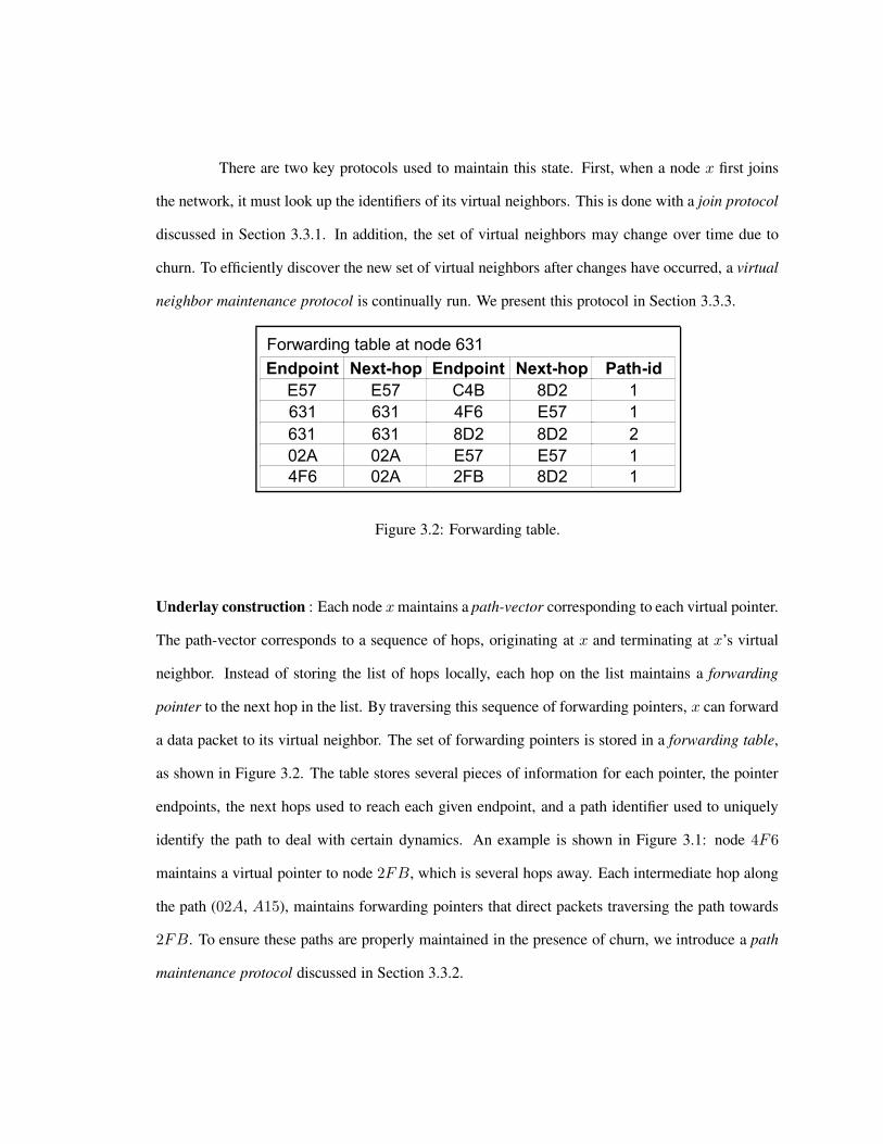
There are two key protocols used to maintain this state. First, when a node x first joins
the network, it must look up the identifiers of its virtual neighbors. This is done with a join protocol
discussed in Section 3.3.1. In addition, the set of virtual neighbors may change over time due to
churn. To efficiently discover the new set of virtual neighbors after changes have occurred, a virtual
neighbor maintenance protocol is continually run. We present this protocol in Section 3.3.3.
Figure 3.2: Forwarding table.
Underlay construction : Each node x maintains a path-vector corresponding to each virtual pointer.
The path-vector corresponds to a sequence of hops, originating at x and terminating at x’s virtual
neighbor. Instead of storing the list of hops locally, each hop on the list maintains a forwarding
pointer to the next hop in the list. By traversing this sequence of forwarding pointers, x can forward
a data packet to its virtual neighbor. The set of forwarding pointers is stored in a forwarding table,
as shown in Figure 3.2. The table stores several pieces of information for each pointer, the pointer
endpoints, the next hops used to reach each given endpoint, and a path identifier used to uniquely
identify the path to deal with certain dynamics. An example is shown in Figure 3.1: node 4F6
maintains a virtual pointer to node 2FB, which is several hops away. Each intermediate hop along
the path (02A, A15), maintains forwarding pointers that direct packets traversing the path towards
2FB. To ensure these paths are properly maintained in the presence of churn, we introduce a path
maintenance protocol discussed in Section 3.3.2.

3.2 Packet forwarding
Figure 3.3: Example: forwarding a packet.
Figure 3.4: Example: forwarding a packet using the shortcutting optimization.
The goal of forwarding is to deliver a packet to a specified destination identifier. The key
challenge in forwarding is that scalable routing protocols must not store global state for the entire
network. However, in the absence of global network state, a node may not know the location of the
destination node. The traditional way to deal with this is to assign locators, but in identity-based
routing we cannot use network location to forward packets.
In this section we describe an algorithm that leverages the state described in the previous

section to perform forwarding. We start by describing a first-cut approach that correctly forwards
packets, but uses inefficient paths. We then describe an optimization called shortcutting that drasti-
cally improves path efficiency. We then present the details of the algorithm used to select the next
hop to forward a packet (Algorithm 1).
If the state in Section 3.1 can be properly maintained, then any node can transmit packets
to any other node in the network. One simple, but inefficient, way to do this is to have the source
node s send the packet to the virtual pointer p that is numerically closest to the destination d. In other
words, s computes the numeric distance along the ring between d and each of its virtual pointers,
and selects the virtual pointer with smallest numeric distance. By doing this, s maximizes progress
through the namespace. At each intermediate hop between s and p, forwarding pointers are used
to make progress to p at each intermediate hop. When p receives the packet, if it is not the final
destination, it repeats the process by looking up its virtual pointer closest to the destination. It is
important to note that nodes do not maintain complete state for the ring, as this would not scale.
Each node only maintains state associated with virtual neighbor pointers. However, by forwarding
along these pointer relationships, any node can forward to any other node.
An example is shown in Figure 3.3. Suppose node 631 wishes to send a data packet to
node 2FB. 631 does not have a path-vector to 2FB, and hence cannot forward the packet directly.
However, 631 does have a path-vector to 4F6, which is closer in the namespace to the destination
2FB than 631 is. 631’s other option is to forward to 8D2, but 8D2 makes less progress than 4F6.
In fact, 8D2 is even further away than 631. Hence, 631 forwards the packet to 4F6. When 4F6
receives the packet, it performs a similar procedure to locate the next virtual hop that maximizes
progress. In this case, 4F6 has a pointer to the final destination, and hence forwards the packet
directly.
However, this approach is not efficient. We would like the path used by the algorithm to
be nearly as long as the shortest-path between the source and destination, but the paths used by the
algorithm above are very long in large networks. In particular if there are n nodes in the network,

then O(n) virtual pointers are traversed on average to reach the destination, leading to very long
paths. To reduce these path lengths, we use an optimization called shortcutting. We observe that
each node knows about not only virtual pointers that it itself maintains, but also virtual pointers
corresponding to path-vectors traversing itself. We exploit this by having each network-level hop
traverse the entire set of entries in the forwarding table to look up the closest endpoint, before
forwarding the packet to the next hop.
An example is shown in Figure 3.4. Suppose node 4F6 wishes to forward a data packet
to node C4B. 4F6 starts by selecting its virtual neighbor that maximizes progress along the ring,
which in this case is 2FB. Hence 4F6 forwards the packet towards 2FB. Ordinarily, the packet
would traverse the path (4F6,02A,2FB). However, 02A maintains a virtual pointer to E57, which
is closer in the namespace to the final destination C4B than is 2FB. Hence when the packet
reaches 02A, instead of naively forwarding the packet on towards 2FB, 02A will forward the
packet towards E57, since E57 is the pointer at 02A that makes the most progress along the ring
towards the destination. Again however, shortcutting is invoked before the packet reaches E57. In
particular, note that E57 maintains a path to its virtual neighbor C4B. Assume this path traverses
E57 − 631 − 8D2 − C4B. In this case, node 631 maintains a forwarding table entry pointing to
C4B. Hence when the packet reaches 631, 631 will forward the packet directly towards C4B.
In this example, the packet traversed four hops. However, we note that the shortest path
between the two points is only three hops. This is a shortcoming of IBR: routing latency is increased
since shortest paths are often not used. However, on a large class of networks, including wireless
and wired topologies, this stretch penalty is very low. We study performance of the protocol through
implementations and simulations, which will be discussed in detail in Chapters 4 and 5.
Each node uses a lookup algorithm to determine the virtual pointer that maximizes progress
to the destination. This algorithm works by traversing the forwarding table, and selecting the virtual
pointer that minimizes numeric distance along the ring to the final destination. We refer to this
algorithm as GetNextHop, and it is shown in pseudocode form in Algorithm 1. GetNextHop takes

three arguments: the identifier of the current network-level hop x, the final destination d, and an
endpoint k to be blocked from consideration. Parameter k is used to route to the closest predecessor
of a given identifier, which is done when joining. First, the algorithm checks to see if the current
hop is the destination, or if the node is the first node in the network. If so, it delivers the packet
locally. Next, we iterate through each entry in the forwarding table, looking for the endpoint that
is numerically closest to the destination. Numerical distance between two identifiers is computed
using RingDist (Algorithm 2). Once the closest endpoint is found, GetNextHop then returns the
next network-level hop towards that endpoint.
Algorithm 1 GetNextHop(uint myid, uint destid, uint blockid)1: if blockid 6= myid && myid==destid then return myid
2: if ftable.size==0 then return myid
3: uint curr=myid
4: for entry en in ftable do
5: if en.endpoint==blockid then continue;
6: if en.endpoint==destid then return destid
7: uint dep=RingDist(en.endpoint,destid);
8: uint dcur=RingDist(curr,destid);
9: if dep < dcur then curr=en
10: if (dep==dcur) && (en.endpoint < curr) then curr=en
11: end for
12: return curr
Algorithm 2 RingDist(uint srcid, uint destid)1: uint incdist=0, decdist=0;
2: if srcid < destid then incdist=destid-srcid;
3: else incdist=destid+(MAXINT-srcid+1);
4: if srcid < destid then decdist=srcid+(MAXINT-destid+1);
5: else decdist=srcid-destid;
Alternate delivery models: In addition to unicast routing, IBR provides support for several other

delivery models. For example, anycast is a routing scheme where a packet is routed to the “nearest”
or “best” of a set of destinations. Anycast is used to balance load across servers, or to select the
closest replica of an object in a content distribution system. We refer to the set of destinations
willing to accept the packet as an anycast group. Each node wishing to participate in anycast group
G selects an identifier of the form [G,X], where X is a unique suffix. A node n sending to the group
selects a destination identifier of the form [G,Y ]. The algorithm above will deliver the packet to the
group member with largest suffix X such that X < Y . Hence the suffixes X and Y may be varied to
control routing within the group. For example, by selecting X to be the load of the group member,
and setting Y = 0, packets will be sent to the least-loaded group member. A similar approach may
be used to perform multicast. In multicast, the network delivers the contents of a single transmitted
packet to multiple destinations. Multicast has been used in Video on Demand systems to stream
content to multiple receivers without incurring the network bandwidth requirements of a unicast-
based approach.
3.3 Maintenance
Thus far, we have described the state maintained by IBR and how packets may be for-
warded using that state. However, we have not yet described how to build this state as node join the
network. In particular, somehow each node needs to discover paths to its virtual neighbors without
being able to observe global state for the entire network. Moreover, we would like to be able to
maintain this state during network-level changes. For example, if links or nodes fail, we would like
to perform any necessary steps to ensure nodes can continue to reach each other.
In this section we describe a set of distributed protocols to build IBR’s state. First, we
present a join protocol in Section 3.3.1 that updates network state to insert a single node into an
otherwise static network. This protocol works by looking up the identities of the joining node’s
virtual neighbors, and then building network-layer paths to each of them. Then, in Sections 3.3.2
and 3.3.3, we describe a protocol that maintains this state in the presence of network dynamics.

3.3.1 Join protocol
Figure 3.5: Example: a new node joins the network.
Here we describe how to add a new node to a network. There are two main steps. First,
the node discovers its virtual neighbors. Next, it must build path-vectors to ensure it can directly
reach each of its virtual neighbors. Finally, its virtual neighbors must tear down paths to nodes that
are no longer their virtual neighbors. When this process completes, the new node will be just like
any other node in the network: it can route to any other node by traversing its overlay neighbors,
and any other node can route back to it for the same reason.
The key challenge in performing these tasks is that the joining node J cannot use the
routing algorithm described in the previous section to route, since J has not yet joined. However,
if J has a physical neighbor R in the network that has already joined, then J can use R as a proxy
to send and receive packets. In particular, J joins by using R as a proxy to forward a join request
towards J ’s identifier. R appends its identifier to the message, to allow remote nodes to route back
to J using R as a proxy. Since J doesn’t yet exist in the network, the packet will be delivered to J ’s
predecessor P on the ring. The predecessor is the node with the largest identifier smaller than J ’s
identifier. When P receives the join request, it constructs a set containing its own identifier, and the
identifiers of all its virtual neighbors, and returns this set back to J via R. J can then determine its

virtual neighbors by observing the contents of the set. Namely, J selects the r/2 closest identifiers
to its own identifier, from the left and right sides of J ’s position on the ring.
When this process completes, J is aware of the identifiers of its virtual neighbors, but has
no way to forward packets to them. J cannot continue relying on R for this purpose, since R may
fail or move to a new location in the future. Hence, J builds paths to each of its virtual neighbors. It
does this by forwarding a path setup message to each of its virtual neighbors vi. Each network-level
hop that the message traverses adds an entry to its forwarding table containing vi’s identifier, and
the the identifier of the next hop towards vi. As an optimization, J load balances these messages
out different physical neighbors, so as to reduce fate sharing if the proxy R fails at a later time.
An example is shown in Figure 3.5. Suppose node 1C5 arrives and wishes to join the
network. 1C5 starts by sending a path setup message with the destination set to its own identifier.
Since initially 1C5 has no virtual neighbors, it forwards the message using node 631 as a proxy.
The message is routed using normal IBR-style forwarding until it reaches 1C5’s predecessor 02A.
02A constructs the set {E57, 02A, 2FB} containing its own identifier and the identifiers of its
virtual neighbors. 02A then sends the set back to 1C5 again using 631 as a proxy. 1C5 selects
{02A, 2FB} as its virtual neighbors. Next, 1C5 sends a path-setup message to 2FB. As the
message is forwarded, each intermediate hop adds a forwarding table entry pointing to the next hop
along the path. In particular, 631 adds the entry (endpoint = 2FB, nexthop = 8D2), 8D2 adds
the entry (endpoint = 2FB, nexthop = A15), and so on. This process is then repeated to build a
path to 1C5’s other virtual neighbor 02A.
The details of the join process are given in Algorithms 3 through 6. First, the joining node
J calls JoinNewNode (Algorithm 6). Each node maintains an adjacency table containing its physi-
cal neighbors. JoinNewNode scans this table and selects a random physical neighbor R to use as a
proxy for the joining process. Next, the node sends a setup-request message towards its own iden-
tifier. The message is sent via the proxy, which uses GetNextHop to forward the message onwards.
When the message is resolved at the joining node’s predecessor P , P calls DeliverSetupRequest

(Algorithm 3). DeliverSetupRequest checks to see whether J should be one of its virtual neighbors.
Since P is J ’s predecessor, J will be added, and P will send a path-setup message back to J using
the proxy R. When J receives the message, it calls DeliverSetup (Algorithm 4), which inserts R
into J ’s virtual neighbor set.
Algorithm 3 DeliverSetupRequest(uint src, uint dst, uint proxy)1: FTEntry rm = virtualpointers.add(dst)
2: if virtualpointers.contains(dst) && !FTable.contains(dst) then
3: sendPathSetup(dst,proxy)
4: if rm 6= NULL then
5: forwardTeardown(myid,myid,rm.dst,rm.pathid)
Algorithm 4 DeliverSetup(uint src, uint dst, uint pathid, uint proxy)1: virtualpointers.add(dst)
2: if virtualpointers.contains(dst) then
3: forwardTeardown(myid,src,dst,pathid)
Algorithm 5 ForwardTeardown (uint nexthop, uint src, uint dst, uint pathid)1: if FTable.contains(src,dst,pathid) then
2: { ftset }=FTable.remove(src,dst,pathid)
3: for entry i in { ftset }
4: forwardTeardown(i,src,dst,pathid)
5: if !FTable.containsentry(src)
6: virtualpointers.remove(src)
7: if !FTable.containsentry(dst)
8: virtualpointers.remove(dst)
This section described how to add a single node to an otherwise static network. How-
ever, practical networks are rarely static. To maintain the ring structure in the presence of network
dynamics, IBR leverages a pair of maintenance algorithms. First, there is a path-maintenance al-
gorithm which aims to ensure that if two nodes a and b are connected by a virtual pointer, then a

Algorithm 6 JoinNewNode()1: uint proxy=GetRandomPhysNeighbor()
2: if proxy 6= null
3: sendSetupRequest(myid,proxy)
can forward packets to b and vice versa. Path maintenance ensures path-vectors are properly main-
tained by ensuring every pair of nodes connected in the namespace are connected in the network.
Second, there is a ring-maintenance protocol that properly maintains the virtual ring. It does this by
ensuring nodes maintain pointers to only their r/2 closest neighbors on the ring. Path-maintenance
is described next in Section 3.3.2, and ring-maintenance is described in Section 3.3.3.
3.3.2 Path maintenance
Figure 3.6: Example: path-vector maintenance.
The goal of path maintenance is to ensure each pair of virtual neighbors is connected by
a path-vector, and that the path-vector is properly maintained. In particular, if a path fails, state
associated with failed paths must be removed, and the endpoints of the path must be notified of
the outage so they can recover the path or discover their new virtual neighbors. Moreover, state
upstream of failures must also be removed for garbage-collection purposes. There are two key
problems that need to be solved here. First, nodes that are physically adjacent to the failure must
detect the failure. Second, after a failure is detected, nodes need to delete state
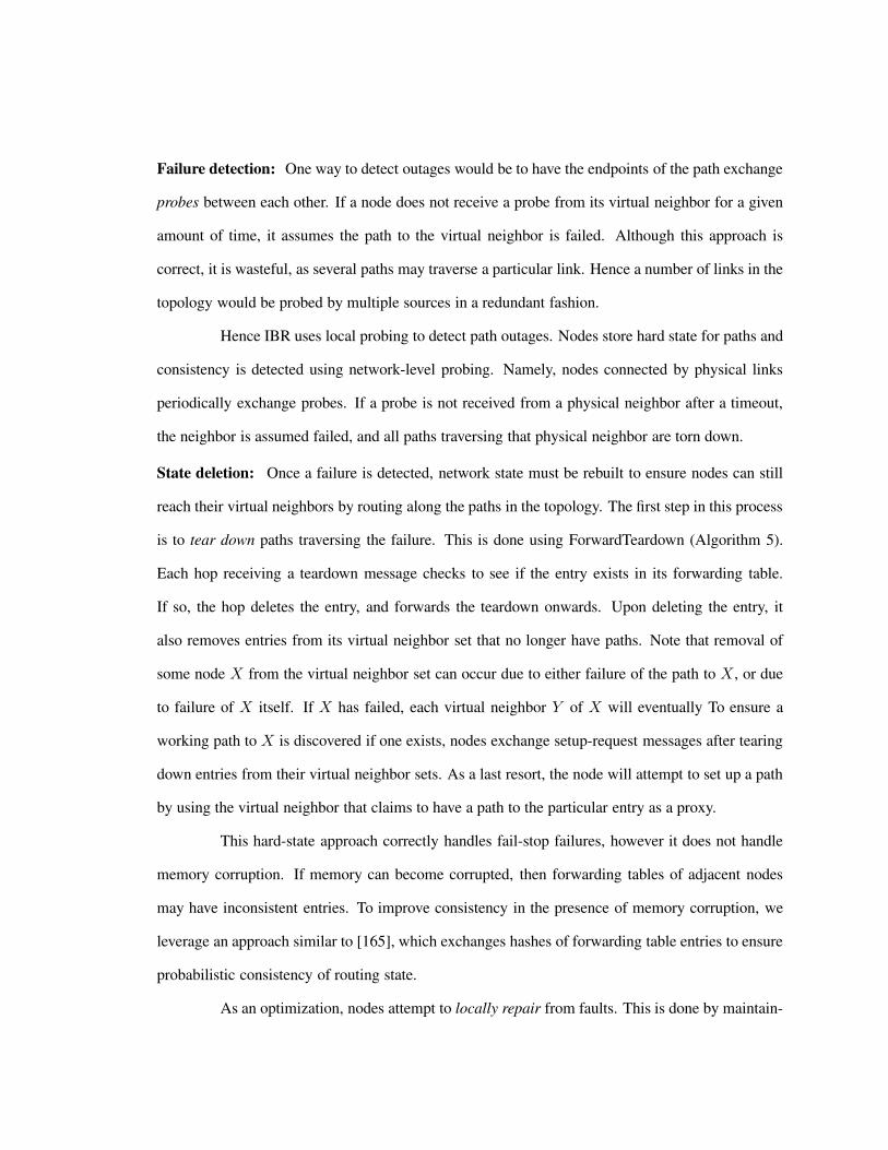
Failure detection: One way to detect outages would be to have the endpoints of the path exchange
probes between each other. If a node does not receive a probe from its virtual neighbor for a given
amount of time, it assumes the path to the virtual neighbor is failed. Although this approach is
correct, it is wasteful, as several paths may traverse a particular link. Hence a number of links in the
topology would be probed by multiple sources in a redundant fashion.
Hence IBR uses local probing to detect path outages. Nodes store hard state for paths and
consistency is detected using network-level probing. Namely, nodes connected by physical links
periodically exchange probes. If a probe is not received from a physical neighbor after a timeout,
the neighbor is assumed failed, and all paths traversing that physical neighbor are torn down.
State deletion: Once a failure is detected, network state must be rebuilt to ensure nodes can still
reach their virtual neighbors by routing along the paths in the topology. The first step in this process
is to tear down paths traversing the failure. This is done using ForwardTeardown (Algorithm 5).
Each hop receiving a teardown message checks to see if the entry exists in its forwarding table.
If so, the hop deletes the entry, and forwards the teardown onwards. Upon deleting the entry, it
also removes entries from its virtual neighbor set that no longer have paths. Note that removal of
some node X from the virtual neighbor set can occur due to either failure of the path to X , or due
to failure of X itself. If X has failed, each virtual neighbor Y of X will eventually To ensure a
working path to X is discovered if one exists, nodes exchange setup-request messages after tearing
down entries from their virtual neighbor sets. As a last resort, the node will attempt to set up a path
by using the virtual neighbor that claims to have a path to the particular entry as a proxy.
This hard-state approach correctly handles fail-stop failures, however it does not handle
memory corruption. If memory can become corrupted, then forwarding tables of adjacent nodes
may have inconsistent entries. To improve consistency in the presence of memory corruption, we
leverage an approach similar to [165], which exchanges hashes of forwarding table entries to ensure
probabilistic consistency of routing state.
As an optimization, nodes attempt to locally repair from faults. This is done by maintain-

ing the next-next hop along the path for each forwarding table entry. When node X detects a failure
of its link to Y , it issues a local broadcast to determine if the next-next hop is reachable via an
alternate path. If it finds an alternate path, it updates its local state and sends a local-repair message
to create forwarding table entries along the alternate path. If it cannot discover an alternate path, it
calls ForwardTeardown to delete the path. Performing local repair allows failures to be recovered
at the network-level without invoking ring maintenance. From our evaluations, we found this im-
proves performance drastically, since the bottleneck for convergence lies not in path maintenance
but in ring maintenance.
Figure 3.7: Example: local repair.
An example is shown in Figure 3.7. When node A15 fails, its neighbor 8D2 detects the
outage and triggers repair of the path (1C5, C4B). First, 8D2 sends a message to its neighbors
querying for paths to the next-next hop 2FB. Upon receipt of the broadcast, E57 responds. 8D2
then modifies its forwarding table to point to E57 as a next-hop, then sends a path-setup message
to 2FB using E57 as a proxy.
3.3.3 Ring maintenance
Next, we aim to ensure that the structure of the ring is maintained during churn. To do
this, we run a ring maintenance protocol that ensures each node x eventually converges to point to

Figure 3.8: Examples: ring misconvergence.
its r/2 left and right neighbors on the ring. We handle this by a pair of mechanisms. First, there is a
base mechanism that ensures every node can discover another node in the ring. Second, there is an
inductive mechanism, that consists of an iterative process wherein the node makes progress towards
its globally correct successor.
At first glance, this may seem like a simple problem. However, without the protocol
described in this section, the ring may converge to an incorrect state. Moreover, it is worth noting
that previous work on ensuring consistency of DHTs does not address this problem, although our
design is inspired by that work. In a traditional DHT, a variety of network-layer failure modes are
masked by IP, whereas IBR is exposed to and must deal directly with them. Here we give two
examples of misconverged rings that can occur in the absence of ring maintenance.
Example, loopy cycle: Certain join orderings may cause a loopy cycle. Such networks
have two properties. First, the network is weakly stable [148], that is, for every node n, we have
predecessor(successor(u)) = u. Second, the network is not strongly stable [148], that is, for some
node m, there exists a node v in n’s component such that n < m < successor(n). An example
is shown in Figure 3.8a. Each node is correctly ordered between it’s predecessor and successor.
However, several nodes do not have their correct global successors, e.g. 02A.
Example, ring partition: Network-level partitions can cause the virtual topology to

break apart into multiple rings. After the network-partition heals, the virtual topology will remain
partitioned. In such cases, the set of successor relationships does not form a spanning graph over the
network topology. An example is shown in Figure 3.8b. Here, nodes C4B and 631 are connected
by a physical path in the network-level topology, yet they are part of two separate rings. Since they
are disconnected in the virtual topology, C4B cannot route to 631 by traversing linearly around the
ring. Traditional DHTs [147, 129, 134, 176] cannot recover from network partitions without outside
help. However, IBR is exposed to such failures and must recover from them directly.
Next, we describe our approach to maintaining consistency of the ring. The algorithm
works by picking a representative for each partition, and maintaining routes from each node to the
representative for its partition. Representatives may change over time due to failure or churn, and
we hence run a distributed protocol to select the node with the numerically smallest identifier as the
partition’s representative at any point in time. We use a DSDV-like mechanism to propagate routes
to representatives.
Background: Our approach leverages the FloodMin algorithm [100] Given a graph G = (V,E),
where each vertex v ∈ V is labeled with an identifier, FloodMin determines the vertex with the
smallest identifier in the network. This is done as follows. Every vertex maintains a record of the
minimum id observed so far. This record is initialized on startup to the vertex’s own identifier.
During each round, this minimum identifier is propagated to each of its neighbors. In a network of
diameter d and n nodes, after d rounds (and nd messages) the records at all nodes are equal to the
minimum id in the system.
Next we describe an extension to FloodMin that, in addition to determining the smallest
id in the network, also gives each node a path to that smallest id. The extension works as follows.
Instead of simply maintaining a record containing the smallest id seen so far, the record also contains
the current shortest path used to reach that id. When the id in the record is propagated to a node’s
neighbors, the vertex is appended on to the end of the shortest path. After nd steps, the record at
each node contains the smallest id in the system and also a network-level path that can be used to

reach the vertex containing that id.
The algorithm is based on two key observations. First, if the ring has misconverged, then
there are multiple nodes that believe they are globally smallest. Second, if these nodes can discover
each other, they can order themselves along the ring to fix the misconvergence. The goal of this
algorithm is to ensure that each node is able to discover its correct global successor on the ring. The
algorithm consists of two parts: a base mechanism, and an inductive mechanism.
Base mechanism: The base mechanism ensures that the entire set of successor relationships form
a single spanning graph over the network topology. The successor relationships may be incorrect,
in that a node might not point to its global successor, but the inductive mechanism will adjust
these successor pointers until they are correct. The base mechanism works by running FloodMin in
parallel with IBR. After IBR has converged, nodes execute a correctness check based on state they
have learned through FloodMin. This correctness check detects misconverged rings by ensuring
nodes that believe they are globally smallest are able to discover each other’s presence.
In particular, we define the ”zero-node” to be a node whose identifier is smaller than both
its left and right virtual neighbors. In any correctly-converged ring, there is exactly one zero-node.
Now consider an incorrectly converged DHT, and assume the system has converged and the network
is not partitioned. There are three cases: either there is one or more loopy cycles, or the DHT is
partitioned into multiple rings, or there are both loopy cycles and partitions. In either case, there
are multiple zero-nodes. For example if the DHT is partitioned into two rings there will be two
nodes that each think they are closest to zero. In the case of loopy cycles, the node with the smallest
identifier in each loop will be a zero-node.
We now ensure zero-nodes always discover each other. Consider the set of zero nodes in
the network. One of these zero-nodes will be the actual globally minimum id G, i.e., the node in
the network with the smallest id. After FloodMin converges, every node will know G’s identifier.
Moreover, each node will have a path to G. If a zero node Z discovers a node other than itself via
FloodMin, then it activates the misconvergence-recovery protocol described below.

The details of this procedure are shown in Algorithm 7. Each node maintains a record r as
a zero-node candidate. Namely, r represents the smallest node observed thus far, which is reachable
from n. Upon receiving an update with identifier nr.id, node n checks to see if nr.id is numerically
smaller than than r.id. If so, it sets r.id equal to nr.id, and records the path used to reach nr.id.
Upon failure, a similar procedure is used to update r to the next-smallest identifier in the network.
Inductive mechanism: The inductive mechanism ensures that the successor relationship for each
node X eventually converges to X’s global successor. This step works by having each node X
periodically execute two checks:
• Consider X’s successor X.S, and X.S’s predecessor X.S.P . If X.S.P is a better match for
X’s successor than X.S, then set X.S = X.S.P .
• Consider the zero node Z . If Z is a better match for X’s successor than X.S is, then set
X.S = Z .
When Z detects that it not the global minimum id, it knows that its predecessor Zp is
incorrect. It knows this because Zp is numerically larger than Z , when in fact there is a smaller
identifier in the network G that should be between Z and Zp. When this happens, Z adds G as its
predecessor in place of Zp. In IBR, when a node’s virtual neighbor set changes, it sends updates to
every node in the union of the new and old predecessor/successor list. Hence, G will be informed
about Z , and Zp will be informed about G. After this happens, Zp, G, Z will be correctly ordered.
During the next exchange of virtual neighbor set changes, Zp’s, G’s, and Z’s pred/successors will
be correctly ordered. During each exchange, the size of the correctly ordered portion of the ring
grows by at least one node, leading to convergence in O(n) steps.
While it is correct to run misconvergence-recovery continuously, doing so may harm per-
formance. In particular we have found from simulations that overhead during churn is increased
substantially if the ring prematurely wraps at the incorrect location. Hence as an optimization we
assign a timer to each node and avoid invoking misconvergence-recovery during network startup.

The details of the inductive mechanism are shown in Algorithm 8. To increase the like-
lihood that the network has converged, n delays before invoking the algorithm. After the delay, n
checks to see if r.id belongs in its virtual neighbor set. If so, it computes a set containing the union
of its own identifier with the identifiers of its virtual neighbors, and forwards this set to each of its
virtual neighbors. When this process completes, each node’s successor and predecessor pointers
will be correct.
Algorithm 7 BaseUpdate (n, r, nr) is executed whenever node n with a record r receives an update
from a neighbor containing a record nr.1: // if nr is lower than r, flood change
2: if nr.id < r.id then
3: r.id=nr.id
4: r.path=concat(nr.path,n.id)
5: send to neighbors(r)
6: end if
Algorithm 8 InductiveCheck (n, r) is executed to detect and repair ring inconsistencies.1: // if the global min id belongs in our virtual neighbor set, add it
2: if n.pred.id > n.id & r.id < n.id then
3: informset={n.pred.id, r.id, n.succ.id}
4: predsucclist={n.pred.id, r.id, n.succ.id}
5: n.pred.id=r.id
6: message msg.idlist=I;
7: send to(I,msg)
8: end if
3.3.4 Examples
We now return to the examples in Figure 3.8 to demonstrate operation of the protocol.
Example, loopy cycle (Figure 3.8a): Suppose the network has converged with a loopy
cycle as shown in the figure. FloodMin will determine node 2 as a global minimum, and all nodes

will have routes to 2. In this case, both 2 and 3 will consider themselves as zero nodes. When 3
notices that there is another zero node with id 2, it will add 2 as its predecessor and send updates to
9 and 2. When 2 adds 3, it sends updates to 3,4,8. When 3 receives the update from 2 containing 4,
3 adds 4 into its successor list and sends updates to 4,5. When 4 gets that update it adds 5 and sends
updates to 5,7. When 5 gets that update it adds 7 and sends updates to 7,8. When 8 receives that
that message it adds 9 and sends an update to 9. At this point the ring has correctly converged into
a single correct ring.
Example, ring partition (Figure 3.8b): Suppose the network has converged with a par-
tition as shown in the Figure. In this case, FloodMin will again provide all nodes with a route to
2. In this case, 4 will discover that 2 is its correct predecessor. It will update its predecessor list to
contain 2 and send updates to 2,8,5. When 8 receives the update it will add 9 into its successor list
and send updates to 5,9. When 9 adds 8 it will send an update to 7, which adds 8 as its successor
and sends updates to 5,8,9. When 5 receives that update it adds 7 as its successor and sends updates
to 4, 5. Meanwhile, when 2 added 4 it sent an update to 3, which in turn added 4. At this point the
rings have converged correctly into a single ring.
3.4 Analysis
So far, we have presented protocols for forwarding packets, joining new nodes to the
network, and maintaining network state in the presence of churn. However, we have not made any
arguments about whether they are correct, i.e., under what conditions a packet will arrive at its
correct destination.
In this section we show IBR maintains a reachability property in steady-state. In other
words, for any two nodes A and B that are connected by a network-layer path, IBR eventually
converges to a state where A can forward packets to B. Moreover, we show that IBR converges
within a polynomial time and a polynomial number of messages after network-level events.
We show this in two steps. First, we show that if a node X has selected node Y as a virtual

neighbor, then X can forward packets directly to Y . We do this by showing X can maintain a path
through the network to Y that is properly maintained in the presence of failures and churn. This
property is shown in Section 3.4.1. Next, we show that each node can discover its correct virtual
neighbors. In particular, IBR provides the property that each node X points to the node immediately
adjacent to itself on the ring (i.e., its successor). This is shown in Section 3.4.2.
3.4.1 Path-consistency
In this section we show that paths are maintained consistently during failures. We assume
that during fail-stop failures, link-detection ensures that physical neighbors of the failed node dis-
cover the failure We show correctness of network-level paths by showing that the path is setup and
maintained correctly.
Definitions: We say a pair of nodes A and B are consistently connected if there is a loop-free
chain of forwarding entries starting at A and terminating at B. We refer to this chain of forwarding
entries as a network-path.
Lemma 1 If a node along a path Pi fails, all state associated with Pi is eliminated.
Proof: Suppose node n fails along path Pi. The nodes a and b adjacent to n detect the failure
and generate teardown messages. Since the teardown message contents uniquely specifies the path,
it only removes state associated with Pi. Moreover, either the teardown message will traverse all
nodes on Pi, or the message will encounter a failed node, in which case the nodes adjacent to that
failure will generate a teardown message to remove the remaining state upstream from that node.
Lemma 2 For each path Pi traversing a failed node, after local repair is performed, either Pi forms
a new consistently-connected path or all state associated with the path is eliminated.
Proof: If local repair discovers an alternate path around n, a setup-message is sent via the alternate
path which forms a new network-path. Either the setup succeeds or it encounters a failure along the

path, in which case a teardown is initiated. The teardown removes all state associated with Pi given
Lemma 1.
Property I: Consider a packet p sent along a network-path from node A to node B. If no
events affect nodes on the network-path while p is in flight, p will arrive at B.
Proof: Invariants 1 and 2 taken together ensure that A and B are connected by a network-path.
Each hop along the path contains a monotonically decreasing sequence number associated with the
path state. Hence a packet forwarded from A makes progress in this sequence-number space at each
hop along the path until it reaches B
3.4.2 Ring consistency
In this section we show that the set of successor relationships converge into a single glob-
ally consistent Hamilton cycle. We do this by showing that the composition of successor rela-
tionships correctly converges into a ring within a polynomial number of steps. We do this by an
inductive proof:
Lemma 3 We say a protocol has converged to a correct state iff each node X’s successor is cor-
rect, i.e., X’s successor points to X’s immediate namespace-increasing neighbor on the ring. After
convergence, if the protocol has not converged to a correct state, then there are multiple zero nodes.
Proof: Suppose otherwise. Then the protocol has converged to a state that is not correct, and
yet there is only a single zero node in the system. Furthermore, there exists some node X with a
successor Z , when in fact X’s globally correct successor is a different node Y . In this case, X points
to Z when in fact it should point to Y. Consider node Y. Suppose we start at node Y and repeatedly
traverse successors until we reach the first node NY that has a successor SNY numerically smaller
than itself. Now, repeat the process from node Z until we reach the first node NZ that has a successor
SNZ numerically smaller than itself. Since the IBR protocols converged, each node has exactly one
successor and one predecessor. Hence, the path from Z to SNZ must be disjoint from the path
from Y to SNY . Hence SNZ 6= SNY . Note that since both SNZ and SNY have predecessors

numerically greater than themselves, they are both zero nodes. Hence there are multiple zero nodes
in the network, which is a contradiction.
Lemma 4 Suppose the FloodMin and IBR protocols have converged. If the protocol has converged
to an incorrect state with multiple zero nodes, then the ring maintenance protocol repairs the pro-
tocol into a correct state.
Proof: Suppose otherwise. Then there exists a network with multiple zero nodes S = Z1, Z2, . . ..
Consider the node with the smallest id in the entire network Zg. FloodMin provides every node
the id of, and the route to, Zg. Consider one of the zero nodes Zi. Since Zi is a zero node, Zg
must have an id numerically smaller than Zi’s predecessor Zpi. Upon performing the correctness
check Zi will replace its predecessor with Zg , and hence Zi is no longer a zero node. This change
triggers the IBR convergence process. At the end of that convergence process, Zi will not be a zero
node, as the IBR convergence protocol never evicts a numerically-lower predecessor and replaces it
with a numerically-higher one. This process is carried out for each zero node except Zg. When this
process is complete, Zg is the only zero node in the network. Hence the protocol has converged to
a correct state.
Corollary: The convergence process is bounded by O(n4) messages and O(n3) time.
Suppose the ring starts in some arbitrary state. There are several steps that take place to
cause the ring to converge:
• FloodMin propagation: after a change, FloodMin requires d rounds before the leader is
elected, and hence requires O(d ∗ e) messages to converge as shown in [100]. It also re-
quires O(d2) time (d rounds, each taking d time).
• Discovery: an incorrect zero node discovers and contacts the true zero node in O(d) messages
where d is the diameter of the graph. However, the message may be shortcut towards the
incorrect zero node’s true successor and hence the incorrect zero node requires O(k) messages

to initiate the reconvergence process where k is the average shortcut path-length. Similarly,
discovery takes k time.
• Re-merging: vanilla Chord requires O(n2) rounds of strong stabilization, each of which takes
O(n) messages. Each of these messages takes O(k) hops. By the same proof: each round of
stabilization takes O(n) time.
• Total: O(n2 ∗ n ∗ k + d ∗ e + k) = O(n4) messages and O(n3) time.
Lemma 5 After the network has converged, each node points to its global successor.
Figure 3.9: Ring with nodes numbered 0 through N.
Proof: Assume a network with nodes numbered 0..N , as shown in Figure 3.9. Assume the network
has converged. As a base case, we know that N must point to 0. This is true because 0 will be
selected as the zero-node for the network. Since the network has converged, N will learn about 0’s
presence via the algorithm discussed in Section 3.3.3. Hence node N points to its global successor.
As an inductive step, we assume each node from k to N points to its global successor, and
we show this means that k−1 must also point to its global successor k. We show this by considering
the three possible alternatives. First, k−1 may point to some node m1 in the range k+1..0. However,

each of these nodes has a correct predecessor, by assumption. Hence the inductive mechanism in
Section 3.3.3 would ensure k − 1 would switch to point to m1 − 1. Therefore routing hasn’t
converged, resulting in a contradiction. Another possibility is k − 1 points to some node m2 in the
range 1..k − 2. However, the zero node 0 is a better match for k − 1’s successor than any node in
this region. Since routing has converged by assumption, k − 1 is aware of 0’s identifier due to the
base mechanism. Hence k − 1 would switch to point to 0, meaning the network hasn’t converged,
again resulting in a contradiction. Therefore, the only possibility left is that k−1 points to its global
successor k.
Property II: Suppose the network has converged. Consider a packet sent from source S
to destination D. If no events occur while the packet is in flight, IBR ensures the p will reach D.
Proof: This follows directly from Property I and Lemma 5.
3.5 Summary and thesis roadmap
This chapter described IBR, a routing protocol for flat identifiers. We described the state
maintained at each node, and how this state is used to compute paths for forwarding packets. We
then performed a simple analysis to show the protocol converges correctly in the presence of fail-
stop failures, and that it does so within polynomial time.
However, the analysis performed in this section says little about real-world performance.
Real network deployments are typically very different from the abstract graph we considered in this
chapter. To better understand protocol behavior, we undertook two implementations of the protocol:
one in the context of wireless networks (Chapter 4) and the other in the context of wired networks
(Chapter 5).
The next chapter describes a wireless sensornet implementation of IBR. Sensornets con-
sist of small motes which have very limited processing power and transmission capabilities. Our
goal in the next section was to study how well the protocol could handle these constraints in con-
junction with the vagaries and anomalies of wireless channels. We then describe results from a set of

ns2 [192] simulations to characterize performance on a wider variety of topologies and deployment
scenarios.

74
Chapter 4
Application to wireless networks
4.1 Introduction
Several large multi-hop wireless networks have recently appeared on the horizon. Sen-
sor networks [193, 4] numbering in the hundreds of nodes have been proposed to solve real-world
problems in contexts such as target tracking, localization, and environmental monitoring. Wireless
mesh networks [200, 2] leverage wireless LAN technologies to form reliable channels between par-
ticipants. Ad-hoc networks [198, 68] focus on a similar problem, but under more dynamic scenarios
where nodes can move and reconfigure into arbitrary topologies.
These networks are notorious for forcing nodes to operate under very harsh conditions.
Sensornets are heavily resource constrained. Due to their small sizes and widespread deployment,
they have drastically limited computing, memory, bandwidth, and power capacity. Ad-hoc net-
works suffer from losses, failures, and transient outages. The urban environment of wireless mesh
networks such as Rooftop networks [2] exacerbates attenuation and multi-path fading, which dy-
namically affects link quality, causing new topologies to be formed. These harsh conditions lead to
the network undergoing repeated changes, or churn.
By the same token, a large number of applications recently developed for these networks
make use of the notion of persistent identity. There have been several proposals for content routing

in sensornets [130], as well as proposals to perform database-style queries or to perform storage
across collections of motes. In ad-hoc network deployments, it is often essential to perform service
discovery [35], or to build connections to specific people or devices [132].
Unfortunately, the goal of persistent identity has traditionally been at odds with efficiently
handling churn. Hence the approach typically taken in wireless network routing has been to sacrifice
persistent identity. Protocols, like Greedy Perimeter Stateless Routing (GPSR) [78] and Hierarchi-
cal State Routing (HSR) [68], assign location-dependent addresses to nodes. Location-dependent
addressing allows wireless networks to very efficiently handle churn. However, to route to persistent
identifiers, such networks must maintain a location-service to map between the node’s address and
its identifier. Maintaining a location service increases protocol complexity and control overhead.
In this chapter we describe the design and evaluation of Virtual Ring Routing (VRR), a
variant of IBR specifically designed for high performance in the context of wireless networks. Given
the inherently unstable nature of wireless networks, it is highly important that any routing protocol
for these networks gracefully handle outages while forwarding packets as quickly and with as little
loss as possible. Hence we designed VRR to recover quickly from outages, handle churn with low
control overhead, and route data packets with low latency and loss. Through implementations and
simulations, we show in this chapter that VRR achieves these performance goals while preserving
the location-independence and correctness properties of IBR.
VRR has several benefits over traditional wireless routing protocols. First, it provides
persistent identity without the need for a location service. Also, VRR does not require network-
wide flooding as hosts leave and join, which reduces control overhead and resource requirements.
Section 4.2 describes a set of extensions to the base IBR protocol that allow it to operate efficiently
over wireless channels. We then proceed to describe a performance evaluation of IBR based on
a wireless sensornet implementation (Section 4.3) and ns-2 [192]-based simulations (Section 4.4),
and simulations of larger-scale networks (Section 4.4.1). Unless otherwise mentioned, we use the
same configuration parameters across all experiments and implementations.

4.2 Wireless extensions
In this section, we describe Virtual Ring Routing [195], a identity-based routing protocol
for wireless networks. Our primary goals for VRR was to recover quickly from outages with min-
imal churn, and to forward packets with low probability of loss. To achieve these goals, we extend
IBR in three key ways from the version discussed in Chapter 3:
Asymmetric link detection: Correct operation of IBR depends heavily on reliable communica-
tion. Wireless networks are particularly vulnerable to message loss, and wireless anomalies such as
asymmetric links. To deal with this, we leverage a failure detection scheme based on the neighbor
discovery procedure in OLSR [31]. OLSR handles this problem by having each node propagate its
physical neighbors in hello messages. If node n observes a message from physical neighbor p that
does not contain n’s identifier, n concludes n − p is an asymmetric link.
Link estimation: In wireless networks, the presence or absence of a link in the topology is
not a binary notion, as the quality of communication channels can vary significantly over time and
location. However, VRR treats connectivity as a binary relation. To deal with this, we use the
link-estimation scheme described in [166]. This approach computes the probability of successful
communication by observing the loss rate of probes between physical neighbors. If this probability
is lower than a threshold, we remove the link from the graph, and do not allow it to be used for
communication. During early experiments, we found that this approach led to a small fraction
of links repeatedly oscillating between the up and down states. This posed a particular problem
for VRR, as nodes behind the link would have to repeatedly tear-down and reconstruct pointers
traversing the link. To mitigate this problem, we made a slight modification to this scheme by using
high- and low-watermarks to determine when VRR should treat a particular link as up or down.
Representative selection: Wireless networks are particularly prone to partitioning and high churn.
Hence in these networks it is critical that ring maintenance perform quickly and efficiently. To
reduce control overhead, we modify the ring maintenance protocol described in Section 3.3.3 to
piggyback routes to representatives on hello packets. To reduce overhead during partitions (Sec-

tion 3.3.3), representatives wait for a timeout to expire before triggering ring recovery. To reduce
update overhead, we propagate path costs to representatives rather than the entire path. Finally, to
reduce sensitivity to transient loops, we propagate a destination sequence in a manner similar to
DSDV [119].
4.3 Sensornet implementation
This section describes an implementation of VRR for sensornet motes. We deployed the
implementation within a testbed consisting of motes scattered throughout offices in the UC Berkeley
computer science building. The goal of this implementation and deployment was to determine how
well the protocol could perform in the presence of drastic computational and memory constraints.
4.3.1 Experimental setup
Figure 4.1: Sensornet testbed deployment.
We implemented VRR in TinyOS [193], an embedded operating system for sensornet
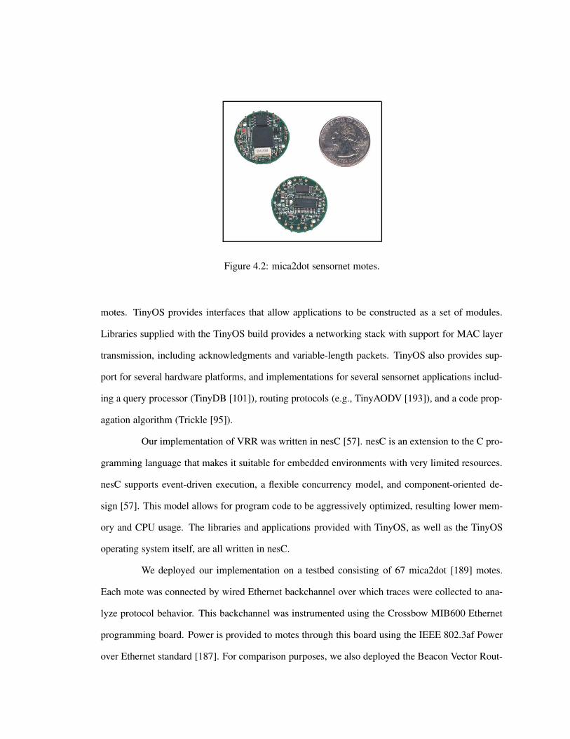
Figure 4.2: mica2dot sensornet motes.
motes. TinyOS provides interfaces that allow applications to be constructed as a set of modules.
Libraries supplied with the TinyOS build provides a networking stack with support for MAC layer
transmission, including acknowledgments and variable-length packets. TinyOS also provides sup-
port for several hardware platforms, and implementations for several sensornet applications includ-
ing a query processor (TinyDB [101]), routing protocols (e.g., TinyAODV [193]), and a code prop-
agation algorithm (Trickle [95]).
Our implementation of VRR was written in nesC [57]. nesC is an extension to the C pro-
gramming language that makes it suitable for embedded environments with very limited resources.
nesC supports event-driven execution, a flexible concurrency model, and component-oriented de-
sign [57]. This model allows for program code to be aggressively optimized, resulting lower mem-
ory and CPU usage. The libraries and applications provided with TinyOS, as well as the TinyOS
operating system itself, are all written in nesC.
We deployed our implementation on a testbed consisting of 67 mica2dot [189] motes.
Each mote was connected by wired Ethernet backchannel over which traces were collected to ana-
lyze protocol behavior. This backchannel was instrumented using the Crossbow MIB600 Ethernet
programming board. Power is provided to motes through this board using the IEEE 802.3af Power
over Ethernet standard [187]. For comparison purposes, we also deployed the Beacon Vector Rout-
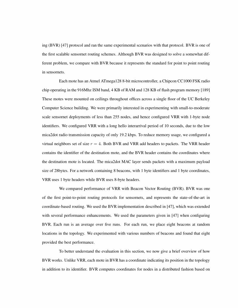
ing (BVR) [47] protocol and ran the same experimental scenarios with that protocol. BVR is one of
the first scalable sensornet routing schemes. Although BVR was designed to solve a somewhat dif-
ferent problem, we compare with BVR because it represents the standard for point to point routing
in sensornets.
Each mote has an Atmel ATmega128 8-bit microcontroller, a Chipcon CC1000 FSK radio
chip operating in the 916Mhz ISM band, 4 KB of RAM and 128 KB of flash program memory [189]
These motes were mounted on ceilings throughout offices across a single floor of the UC Berkeley
Computer Science building. We were primarily interested in experimenting with small-to-moderate
scale sensornet deployments of less than 255 nodes, and hence configured VRR with 1-byte node
identifiers. We configured VRR with a long hello interarrival period of 10 seconds, due to the low
mica2dot radio transmission capacity of only 19.2 kbps. To reduce memory usage, we configured a
virtual neighbors set of size r = 4. Both BVR and VRR add headers to packets. The VRR header
contains the identifier of the destination mote, and the BVR header contains the coordinates where
the destination mote is located. The mica2dot MAC layer sends packets with a maximum payload
size of 28bytes. For a network containing 8 beacons, with 1 byte identifiers and 1 byte coordinates,
VRR uses 1 byte headers while BVR uses 8-byte headers.
We compared performance of VRR with Beacon Vector Routing (BVR). BVR was one
of the first point-to-point routing protocols for sensornets, and represents the state-of-the-art in
coordinate-based routing. We used the BVR implementation described in [47], which was extended
with several performance enhancements. We used the parameters given in [47] when configuring
BVR. Each run is an average over five runs. For each run, we place eight beacons at random
locations in the topology. We experimented with various numbers of beacons and found that eight
provided the best performance.
To better understand the evaluation in this section, we now give a brief overview of how
BVR works. Unlike VRR, each mote in BVR has a coordinate indicating its position in the topology
in addition to its identifier. BVR computes coordinates for nodes in a distributed fashion based on

the vector of distances to a small set of beacon nodes. BVR greedily forwards packets to the next
hop that is closest to the destination in terms of a distance metric computed on the coordinate space.
When forwarding, the packet may reach a node that can make no further progress towards the
destination coordinate. When this happens, BVR forwards the packet to the beacon closest to the
destination in the coordinate space. When the beacon receives the packet, it is flooded with a scope
equal to the number of hops separating the beacon from the destination in the coordinate space.
4.3.2 Results from deployment
0 1 2 3 4 5 6 7 8 9
0 2 4 6 8 10 12 14 0.8
0.85
0.9
0.95
1
Sen
d ra
te (p
kts/
sec)
Frac
tion
of p
acke
ts d
eliv
ered
Time [minutes]
Number of nodesVRR delivery ratioBVR delivery ratio
Figure 4.3: Sensornet experiments: effect of congestion
Effect of congestion: Figure 4.3 shows performance of VRR and BVR in the presence of network
congestion. Here, we first let the protocols converge, then route data packets between random source
and destination pairs. The left y-axis shows the rate at which data packets are sent, and the right y-
axis shows the fraction of data packets that were successfully delivered to their correct destination.
In this experiment, both VRR and BVR perform well. BVR suffers from a slightly higher lossrate
under high levels of congestion. We found that this happens due to increasing levels of link outages.
When congestion increases, links tend to flap, causing BVR’s addresses to change. Hence nodes
on paths not affected by failure can undergo churn. This is not true for VRR, which has fixed
identifiers that do not change in the presence of churn. This allows VRR to maintain higher delivery

40
50
60
70
80
90
100
0 2 4 6 8 10 12 14 0.8
0.85
0.9
0.95
1
Num
ber o
f nod
es
Frac
tion
of p
acke
ts d
eliv
ered
Time [minutes]
Number of nodesVRR delivery ratioBVR delivery ratio
Figure 4.4: Sensornet experiments: effect of failures
0.2
0.3
0.4
0.5
0.6
0.7
0.8
0.9
1
0 10 20 30 40 50 60 70
Frac
tion
of p
acke
ts
Messages per data packet
VRRBVR
Figure 4.5: Sensornet experiments: stretch penalty
rates under high levels of congestion.
Transmission overhead: In Figure 4.4, we show a CDF of the number of broadcasts required to
deliver a data packet to the destination, for each of the two protocols. The x-axis is the number of
broadcasts required to deliver a data packet, and the y-axis is the fraction of data packets requiring
that many broadcasts. Again, both protocols perform well for this experiment. However, we note
that BVR has a slightly longer tail. This happens because BVR is a coordinate-based protocol. Like
several traditional coordinate-based protocols, certain data packets can run into dead-ends when
being forwarded between certain source-destination pairs. In BVR, when a packet hits a dead-end,

a scoped flood is used to discover a path around the dead-end. Scoped flooding leads to an increased
number of broadcasts for these source-destination pairs. In VRR, each node maintains paths to its
left and right neighbors on the ring. This allows it to make progress to any destination regardless of
the structure of the topology. Hence VRR has better performance in the tail of the curve.
Effect of failure: Figure 4.5 measures the effect of failures on delivery ratio. As before, we
let the protocols converge before forwarding packets between random source and destination pairs.
However in this experiment, we simultaneously kill 10% of the sensornet motes to investigate how
quickly each protocol can react to failure. Here, the x-axis is time, the left y-axis is the number of
nodes still alive in the network at that time, and the right y-axis is the fraction of packets successfully
delivered to the destination. Again, both BVR and VRR perform well. However, BVR suffers from
a slight outage after the failure. This happens due to address churn: when the failure occurs, a
significant number of nodes are affected due to address changes, and it takes some time for this to
converge. In VRR, nodes not on failed paths are not affected by the failure, allowing convergence
to take place quickly and the delivery ratio to remain high.
Implementation complexity: Measuring the complexity of a protocol is a challenging research
problem in its own right [128]. In an effort to get a very rough sense of how much work it takes
to implement each of the protocols, we count the lines of code for each of four protocol implemen-
tations (Table 4.1). For the AODV, DSDV, and BVR implementations, we use the code distributed
in the TinyOS package [193]. For each of the protocols, we strip blank lines and lines containing
only comments from each of the source files, and then measure the number of lines remaining. Al-
though VRR contains the largest number of lines of code, it does not consist of substantially more
code than the DSDV or the BVR implementations. We feel that in certain scenarios, this additional
complexity may be a worthwhile tradeoff for the benefits mentioned above.

Table 4.1: Number of lines of code for each of the implementations
Protocol implementation Lines of code
VRR 3927
AODV 1839
DSDV 3168
BVR 3649
4.4 802.11b simulations
We implemented VRR in version ns-2.19 the ns-2 network simulator [192], using the
wireless extensions developed by the CMU Monarch project [16]. The ns-2 simulator provides sup-
port for several radio propagation models and MAC protocols, as well as implementations of several
wireless multihop protocols. We compared performance with AODV, DSR, and DSDV, which are
traditional ad-hoc multihop routing protocols. To ensure comparisons were fair, we configured these
protocols to duplicate the results given in [16]. When comparing with VRR, we used the same sim-
ulation parameters and used the same configuration for network topology. All results were averaged
over five runs.
All results use the following default parameters unless otherwise mentioned. The number
of domains b = 4 and the number of virtual neighbors was r = 4. We used the same topology as
in [16], with 50 nodes randomly distributed over a 1500x300 meter grid with a radio range of 250
meters.
Effect of network size: Figure 4.6 shows control overhead for each of the protocols, where
10% of nodes participate in communication. We can see that the relative benefit of using VRR
increases with topology size. We found this result held across alternate densities and communication
patterns. For example, Figure 4.7 shows results from the same experiment repeated for 20% of nodes
participating in communication.
Effect of network density: Figure 4.8 shows control overhead as a function of network size for

1
10
100
1000
10000
100000
1e+06
1e+07
20 40 60 80 100 120 140 160 180 200C
ontro
l ove
rhea
d [m
sgs]
Number of nodes
VRRAODV
DSRDSDV
Figure 4.6: NS-2 Experiments: Effect of network size, 10% communicating nodes
1
10
100
1000
10000
100000
1e+06
1e+07
20 40 60 80 100 120 140 160 180 200
Con
trol o
verh
ead
[msg
s]
Number of nodes
VRRAODV
DSRDSDV
Figure 4.7: NS-2 Experiments: Effect of network size, 20% communicating nodes
three different network densities. Here, the sparse topology has 12 nodes per 1500x300m area, the
moderate topology has 50 nodes , and the dense topology has 200 nodes. As we increase the number
of nodes along the x-axis, we simultaneously increase the size of the area containing the nodes, so
as to keep density constant. Here, we observe the control overhead increases roughly linearly with
the number of nodes in the network. This is expected, since stretch is roughly constant with network
size [195]. The control overhead is smaller for more dense graphs, as in these networks the network
diameter decreases, resulting in fewer network-level messages to build state.
Breakdown of control overhead: Here, we compared performance for a dense network consisting

0
5000
10000
15000
20000
25000
30000
40 60 80 100 120 140 160 180 200C
ontro
l ove
rhea
d [m
sgs]
Number of communicating nodes
moderatesparsedense
Figure 4.8: NS-2 Experiments: control overhead as a function of network size and density
0
5000
10000
15000
20000
25000
30000
40 60 80 100 120 140 160 180 200
Con
trol o
verh
ead
[msg
s]
Number of communicating nodes
totalv. neighbor lookup
path construction
Figure 4.9: NS-2 Experiments: breakdown of control overhead by message type, sparse network
of 50 nodes per 1500x300 meter area, and a sparse network consisting of 12.5 nodes per 1500x300
meter area. Figures 4.9 and 4.10 break down the control overhead by message type for the sparse
and dense network, respectively. We break messages down into two phases. We refer to the first part
of the join as the virtual neighbor discovery phase, where a node determines the identifiers of its
virtual neighbors. Second, the path construction phase constructs path vectors from a node to each
of its virtual neighbors. Here, the x-axis is the network size, and the y-axis is the number of control
messages attributed to each of these two join phases. We can see that path construction results in
the majority of control messages. This is expected: in a network with diameter d, running VRR

0
2000
4000
6000
8000
10000
12000
14000
40 60 80 100 120 140 160 180 200C
ontro
l ove
rhea
d [m
sgs]
Number of communicating nodes
totalv. neighbor lookup
path construction
Figure 4.10: NS-2 Experiments: breakdown of control overhead by message type, dense network
with r virtual neighbors, we would expect O(d) messages in the virtual neighbor discover phase
and O(rd) messages in the path construction phase. Since for these experiments r = 4, we observe
roughly four times as many messages in the path construction phase.
1
10
100
1000
10000
100000
1e+06
0 5 10 15 20 25 30 35 40 45 50
Con
trol o
verh
ead
[msg
s]
Number of communicating nodes
VRRAODV
DSRDSDV
Figure 4.11: NS-2 Experiments: comparison with traditional protocols, 50 nodes
Comparison with traditional ad-hoc protocols: We start by comparing the control overhead
required to build a network of 50 nodes. Figure 4.11 shows the number of messages for AODV,
DSR, DSDV, and VRR. On the x-axis, we vary the fraction of nodes participating in communication,
and on the y-axis we measure the number of network-level messages required to build the network.

1
10
100
1000
10000
100000
1e+06
0 5 10 15 20 25 30 35 40 45 50C
ontro
l ove
rhea
d [m
sgs]
Number of communicating nodes
VRRAODV
DSRDSDV
Figure 4.12: NS-2 Experiments: comparison with traditional protocols, 100 nodes
1
10
100
1000
10000
100000
1e+06
0 5 10 15 20 25 30 35 40 45 50
Con
trol o
verh
ead
[msg
s]
Number of communicating nodes
VRRAODV
DSRDSDV
Figure 4.13: NS-2 Experiments: comparison with traditional protocols, 200 nodes
Since VRR and DSDV are proactive protocols, their overheads are roughly constant with
the number of nodes participating in communication. For the reactive protocols AODV and DSR,
the control overhead increases as more nodes communicate. We note two things from the figure.
First, VRR’s control overhead is less than DSDV’s. This happens because DSDV maintains routes
between all pairs of nodes, while VRR maintains routes only to each node’s virtual neighbors.
Second, VRR begins outperforming DSR and AODV when there are roughly six nodes participating
in communication. This shows that for networks with even moderately low levels of communication,
VRR can outperform reactive protocols. In Figures 4.12 and 4.13, we repeat the experiment for

networks containing 100 and 200 nodes, respectively. VRR continues to outperform AODV and
DSR in these networks as well, but by a slightly smaller margin. For example, the crossover point
for a 200 node network is when 10 nodes participate in communication.
0.5 0.55
0.6 0.65
0.7 0.75
0.8 0.85
0.9 0.95
1
1 1.5 2 2.5 3 3.5 4 4.5 5
Frac
tion
Stretch penalty
n=25n=50n=75
n=100n=125n=150n=175n=200
Figure 4.14: NS-2 Experiments: stretch penalty, dense network
0.5 0.55
0.6 0.65
0.7 0.75
0.8 0.85
0.9 0.95
1
1 1.5 2 2.5 3 3.5 4 4.5 5
Frac
tion
Stretch penalty
n=25n=50n=75
n=100n=125n=150n=175n=200
Figure 4.15: NS-2 Experiments: stretch penalty
Stretch penalty: A key drawback of VRR is that it incurs a stretch penalty when forwarding
packets. We define stretch as the number of hops traversed by a packet, to the shortest number of
hops through the network. Here, we route data packets between random source-destination pairs,
and plot a CDF of data packet stretch for varying network sizes in Figure 4.15. We can see that

0.5 0.55
0.6 0.65
0.7 0.75
0.8 0.85
0.9 0.95
1
1 1.5 2 2.5 3 3.5 4 4.5 5Fr
actio
n
Stretch penalty
n=25n=50n=75
n=100n=125n=150n=175n=200
Figure 4.16: NS-2 Experiments: stretch penalty, sparse network
aside from particularly small networks, stretch is roughly constant regardless of network size. In
Figures 4.14 and 4.16, we rerun the experiment for sparse and dense networks. We can see that
denser networks have lower median and maximum stretch. This is because in dense networks,
network diameter is decreased, bounding the possible end-to-end length of paths.
4.4.1 Large-scale simulations
The ns2 network simulator was not designed to scale to large topologies, forcing us to
limit our experiments in the previous section to roughly 200 nodes. Although most wireless deploy-
ments today are less than this size, there has been recent interest in studying larger-scale deploy-
ments [27]. Hence in this section we present results from a simulator that scales to larger topologies.
To investigate the sensitivity of the results to the network topology, we use four different
graph types during simulation. First, we use the planar ad-hoc network graphs from the previous
section. Use of these graphs allow us to cross-compare our results to those in the previous section
for purposes of validation. Next, we consider a topology where nodes are arranged in the form of
a square grid. Finally, we use random graphs constructed by the Erdos-Renyi model [199]. This
model takes a parameter p that controls the probability a link exists between a given pair of nodes.
We plot results for two kinds of graphs, one where p = 0.5 and another where p = 0.1.

0
100
200
300
400
500
600
0 500 1000 1500 2000C
ontro
l ove
rhea
d [m
sgs]
Number of nodes
rand-0.1rand-0.5
adhocgrid
Figure 4.17: Larger scale experiments: control overhead as a function of network size.
Control overhead: Figure 4.17 shows the control overhead required to join a single host for
network sizes up to 2000 nodes. For the ad-hoc and grid topologies, the control overhead increases
roughly linearly with network size. this happens because we are holding density constant in these
networks, and hence the network diameter increases roughly with the square root of network size.
However, with the random networks, control overhead is much less and stays roughly constant
with network size. This happens because in random networks, the diameter does not increase with
network size.
1
1.5
2
2.5
3
3.5
4
4.5
5
0 500 1000 1500 2000
Stre
tch
pena
lty
Number of nodes
rand-0.1rand-0.5
adhocgrid
Figure 4.18: Larger scale experiments: data packet stretch penalty.

0
0.2
0.4
0.6
0.8
1
5 10 15 20 25 30S
tretc
h pe
nalty
Number of nodes
rand-0.1rand-0.5
adhocgrid
Figure 4.19: Larger scale experiments: CDF of data packet stretch penalty, 100 nodes.
0
0.2
0.4
0.6
0.8
1
10 20 30 40 50 60 70 80 90 100
Stre
tch
pena
lty
Number of nodes
rand-0.1rand-0.5
adhocgrid
Figure 4.20: Larger scale experiments: CDF of data packet stretch penalty, 1000 nodes.
Stretch: Figure 4.18 shows the stretch penalty required to route data packets to random desti-
nations in networks of varying sizes. Here, the stretch penalty associated with the ad-hoc and grid
graphs is below 2.5, and roughly constant with network size. However, the stretch penalty of the
random graphs is significantly higher. This happens because the number of links, and hence the
number of paths in the random graphs is higher. This makes the shortcutting optimization perform
less effectively: the probability two paths will intersect at an arbitrary point in the topology is much
lower in the random graphs due to this fanout of paths.
Figure 4.19 shows a CDF of data packet stretch for 100 node networks, for the four graph

types. Figure 4.20 shows the same thing but for 1000 node networks. In both cases the grid topology
has a much longer tail than the other graph types. This happens because the grid topology lacks
high degree nodes that are connected to many other neighbors. In the other topologies, these high
degree nodes typically have many paths traversing themselves, which makes shortcutting perform
very efficiently. In grid networks, all nodes have roughly the same degree, reducing efficiency of
shortcutting. Although the worst-case stretch in these figures may be high, the number of nodes
with such high stretch is very low. Hence routes to such nodes may be cached or flooded to reduce
stretch. We explore such techniques further in Chapter 5.
4.4.2 Cross-validation
Thus far, this chapter has presented a sensornet implementation, ns2 simulations, and a
large-scale simulator. Using multiple environments to evaluate performance allows us to consider a
wider range of deployment scenarios and degrees of realism than is possible with a single environ-
ment. However, to understand protocol behavior across the implementations, would be desirable to
say whether each implementation was done faithfully to the original protocol specification.
To evaluate this, we cross-compared results from each of the evaluation environments. To
validate correctness, we configured each of the environments with the same topology of 67 motes
and the same algorithm parameters. One would not expect the results to be exactly the same across
the environments, as they simulate different environments and on different levels of granularity.
Moreover, simulating a wireless network with a high degree of accuracy is itself a challenging
research problem [87, 93]. However, for the same configurations, we would expect to see similar
scaling trends and performance characteristics.
Figure 4.21 shows the stretch penalty of VRR in the ns2 and the large-scale simulator.
We note that the two lines look similar: the majority of packets suffer a stretch of less than two,
while a small number suffer stretch up to roughly 12. In the sensornet simulator (Figure 4.22), we
are able to measure the real latency suffered by packets. In the implementation, very few packets

0
0.2
0.4
0.6
0.8
1
1 2 3 4 5 6 7 8 9 10Fr
actio
n
Stretch penalty
ns2 simulatorlarge-scale simulator
Figure 4.21: Cross-validation experiments: CDF of simulator stretch.
0
0.2
0.4
0.6
0.8
1
1 1.5 2 2.5 3 3.5 4 4.5 5
0 50 100 150 200 250 300 350
Frac
tion
Hops
Latency [ms]
sensornet impl-latencysensornet impl-hops
Figure 4.22: Cross-validation experiments: CDF of implementation latency and hopcount.
suffer more 5ms of latency. When we look at the hopcount and latency traversed by packets, we see
similar macroscale behavior to the simulators. However, we do note that latency in the simulator
has a steeper slope than stretch in the simulators. This is because latency varies substantially over
different paths. VRR prefers links with lower loss, which reduces the number of retransmissions
and hence the time necessary to send a packet. This causes stretch in terms of packet latency to be
reduced lower than stretch in terms of the number of hops traversed by the packet.
Figure 4.23 shows the scaling trends of the three evaluation environments in terms of
control overhead required to add a single node to the network. Since we performed our evaluations
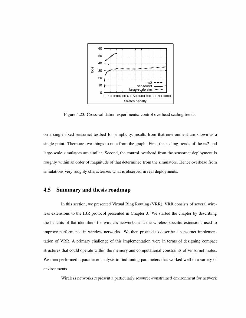
0
10
20
30
40
50
60
0 100 200 300 400 500 600 700 800 900 1000H
ops
Stretch penalty
ns2sensornet
large-scale sim
Figure 4.23: Cross-validation experiments: control overhead scaling trends.
on a single fixed sensornet testbed for simplicity, results from that environment are shown as a
single point. There are two things to note from the graph. First, the scaling trends of the ns2 and
large-scale simulators are similar. Second, the control overhead from the sensornet deployment is
roughly within an order of magnitude of that determined from the simulators. Hence overhead from
simulations very roughly characterizes what is observed in real deployments.
4.5 Summary and thesis roadmap
In this section, we presented Virtual Ring Routing (VRR). VRR consists of several wire-
less extensions to the IBR protocol presented in Chapter 3. We started the chapter by describing
the benefits of flat identifiers for wireless networks, and the wireless-specific extensions used to
improve performance in wireless networks. We then proceed to describe a sensornet implemen-
tation of VRR. A primary challenge of this implementation were in terms of designing compact
structures that could operate within the memory and computational constraints of sensornet motes.
We then performed a parameter analysis to find tuning parameters that worked well in a variety of
environments.
Wireless networks represent a particularly resource-constrained environment for network
protocols. In this chapter, we showed that VRR performs well in such scenarios. However, how
well it would perform in wired networks remains an open question. The general environment of
the Internet has very different operational characteristics from wireless networks. Wired networks
typically have well established links with low loss and lower rates of churn. Moreover, ISPs in the
Internet often instrument their networks with an increasingly complex set of access control rules
and policies that control how packets flow through their networks. To demonstrate applicability of
the protocol to wired networks environments, we develop a version of IBR for wired networks in
the next chapter called Routing on Flat Labels (ROFL). We then proceed to evaluate ROFL through
use of distributed packet-level simulations and an overlay-based implementation and deployment.

96
Chapter 5
Application to the Internet
5.1 Introduction
For a variety of reasons, including the NewArch project [190], various commentaries
[121], NSF’s GENI [183] and FIND [182] programs, and pent-up frustration at the current state
of affairs, it has become fashionable to consider clean-slate redesigns of the Internet architecture.
These discussions address a wide range of issues, and would take the architecture in many different
directions. However, the one point of consensus is that any new architecture should cleanly separate
location from identity. The current use of IP addresses to signify both the location and the identity
of an endpoint is seen as the source of many ills, including the inability to properly incorporate
mobility, multihoming, and a more comprehensive notion of identity into the Internet architecture.
As long ago as Saltzer’s commentary [135] and the GSE proposal [112], and probably even before
that, there have been calls for separating the two, either through new addressing schemes (e.g.,
GSE [112]), or through more radical architectural changes (e.g., TRIAD[28], IPNL [52], HIP [72],
FARA [29], LFN/DOA [5, 163], i3 [146], SNF [75], etc.). All of these proposals define or assume
the existence of an endpoint namespace, but they differ greatly in the nature of the namespace, from
using Fully Qualified Domain Names (FQDNs), to flat names, to namespace-neutral architectures
that allow any namespaces at all.

It has been widely agreed that future Internet designs must cleanly separate location from
identity, and most proposals up to this point have been based on using a resolution service to map
between the two. While splitting location from identity has a number of benefits, at the same time
these proposals incur some serious costs. The use of resolution increases fate sharing. Network
entities share fate if the failure of one party causes the other party to undergo a failure or degraded
service. In a system free of fate sharing, only the parties directly involved in communication should
be involved in establishing and maintaining state associated with the connection. With today’s
Internet, connection establishment shares fate with the DNS hierarchy, as packet delivery must rely
on a name resolution system that typically lies off the data path. Moreover the address management
challenges of today’s networks remain: their associated misconfigurations, and the difficulty of
cleanly supporting mobility, multihoming, and access control.
To address these problems we propose the use of IBR for Internet-scale routing. If this
were possible, such an approach could have several benefits. Fate-sharing would be improved, as a
resolution system becomes unnecessary when communicating with a persistent identifier. Address
management is eliminated, as network protocols may now operate without any use of addresses
whatsoever. Access controls become simpler as well, as they may be managed by identity rather
than addresses which have some inherent dynamism.
However, IBR as described in Chapter 3 does not work for Internet routing. There are
several key challenges that need to be solved. First, network operators apply policies to control
the way packets traverse networks. These policies may be assigned for traffic engineering reasons,
for example to balance load across links. They may be used due to economic considerations, for
example to forward to peers that charge less money for transit. Second, the Internet is much larger
than typical multihop wireless deployments. A recent survey [194] estimates the number of Internet
hosts at over 450 million.
In this chapter, we describe solutions to address each of these challenges. To handle
policies, we provide a mechanism to control the way path-vectors are constructed between virtual

neighbors in manner that obeys a class of widely-used BGP policies. To scale to the size of the
Internet, we provide a locality-based pointer selection strategy that maintains long-distance virtual
pointers in addition to the virtual neighbors immediately adjacent on the ring. The long-distance
pointers are chosen to be nearby in the physical network, to maximize namespace distance for a
given amount of physical distance traversed by packets. We refer to the resulting protocol as Routing
on Flat Labels (ROFL) [196]. ROFL is based on IBR, but contains the extensions discussed above
to make it practical for Internet routing.
Roadmap: We start by giving a high level overview of our design in Section 5.2. We
then provide a more detailed description in two parts. In Section 5.3 we describe intradomain
routing, i.e., routing within a single ISP. Here we describe the basic joining, routing, and failure
recovery algorithms. Next, in Section 5.4, we describe how routes are constructed across ISPs, i.e.,
interdomain routing. Unlike routing within a single ISP, in Interdomain routing not all participants
are owned by the same provider. This introduces a rich variety of challenges, including several
policies that constrain routes to obey relationships between ISPs, and also scaling issues due to the
Internet’s large size.
We then give an overview of other challenges that exist in Internet routing, and touch
on a few more incremental extensions to the basic ROFL design to address these concerns in in
Section 5.5. Next, we discuss our experiences building and results from a distributed simulator and
a deployed implementation in in Section 5.6. Overall, we found that IBR is able to scale to Internet
sizes, providing a stretch penalty of 1.4 and control overhead of 250 messages per host join, in a
network with 300 million nodes.
5.2 Overview
Before we present our design, we should note the three dimensions along which it should
be evaluated.
Architecture: These are the broad issues raised in the previous section about what benefits flow
from routing on flat names.
Features: We will show, in the detailed design sections, that ROFL can support policy routing
(Section 5.4) and can be extended to support anycast and multicast (Section 5.5).
Performance: We will address this through simulations and an implementation, where we study
stretch, join-overhead, and failure-recovery. We found that in networks containing 300 million
nodes, ROFL requires roughly 250 messages to join a single host and incurs a stretch penalty of
roughly 1.4. Further details will be given in Section 5.6.
We start this section by giving a high-level overview of the ROFL design. ROFL is based
on IBR, but contains several extensions to improve performance and policy support in the context of
wired networks. Section 5.2.1 several preliminary modifications we make to apply IBR to Internet
routing. Section 5.2.2 gives an overview of the challenges of routing within a single ISP and our
solution approach. Section 5.2.3 does the same for inter-ISP routing.
5.2.1 Preliminaries
In this section we describe several incremental modifications we make to IBR to provide
better support for Internet routing. First, we describe how nodes compute their identifiers and
how the namespace is constructed. Next, we describe how routers maintain state in the form of
source-routes for scalability reasons, and what state is stored for various types of nodes. Finally, we
describe how failures are detected and how certain kinds of attacks are dealt with. We present the
more significant modifications to IBR in Sections 5.2.2 and 5.2.3.
Identifiers: We use self-certifying identifiers; that is, we assume a host’s or router’s identity is tied
to a public-private key pair, and its identifier (ID) is a hash of its public key. In general, a physical
host can have multiple IDs, and an ID can be held by multiple hosts to implement anycast and
multicast. However, for this simple description we will assume each host and router has a single,
globally unique ID. We wrap these values to create a circular namespace and, as in Chord [147],
we use the notions of successor and predecessor and will establish a ring of pointers that ensures
routing is correct; some additional pointers cached along the way will lead to shorter routes. As
shown in Figure 5.1, nodes maintain pointers to both internal pointers within the same ISP, and
external successors which may reside in a different ISP.
Source routes: As done today, hosts are assigned to a first-hop or gateway router through either
DHCP or manual configuration. A host may have several gateway routers for redundancy purposes.
We say that a host’s ID is resident at this gateway router, so each router maintains a set of resident
IDs in addition to its own ID, and it maintains source routes to their successors on their behalf. We
call the router at which an ID is resident the ID’s hosting router. A source route or path from one
ID to another is a hop-by-hop series of physically connected router IDs that goes from one hosting
router to another.
Classes of nodes: There are three classes of nodes in the system: routers, stable hosts such as
servers and stable desktop machines, and ephemeral hosts that are intermittently connected at a
particular location, either because of mobility, e.g. laptops, or because of frequent shut-downs or
failures, e.g. home PCs turned off when not in use). The decision about whether a host is stable or
ephemeral is made by the authority who administers the router at which it is resident. When we use
the term host without a modifier, we will mean a stable host; ephemeral hosts will be treated as a
special case and dealt with later in this section.
Source-Route Failure Detection: To detect source route failures, ROFL assumes an underlying
OSPF-like protocol that provides a network map. This map provides the router-level topology but
not routes to hosts, and is used to discover failures in the physical network. In the intra-domain case,
this protocol finds paths to other hosting routers within the same AS. In the inter-domain case, this
protocol maintains routes to external border routers whom the internal hosting routers have pointers
to. This protocol can also be used to find the egress router by which an adjoining AS can be reached.
This protocol is used to detect link and node failures, and notifies the routing layer of such events.
Security: The self-certifying identifiers can also help fend off attacks against ROFL mechanisms
itself. When a host is assigned to a hosting router, before its ID can become resident, the host must

prove to the router cryptographically that it holds the appropriate private key. Thus, there can be no
spoofing of IDs unless, of course, the router misbehaves. However, end-to-end verification, from
both routers and hosts, can prevent such spoofing even with a misbehaving router. A more subtle
attack is the Sybil attack [39], where-in a compromised router may concoct identifiers to gain a
larger footprint in the system. Damage control against such attacks may be achieved by auditing
mechanisms within an AS that limit the number of IDs hosted by a router.
In general, a compromised router can indulge in three kinds of attacks. First, a compro-
mised router can aim to disrupt routing by refusing to forward packets sent to it by other routers.
This is a data-plane attack, and can be avoided by redundant routing techniques [21]. Note that
since our IDs are self-certifying, a compromised router cannot spoof responses from the intended
destination. Such spoofing can be detected by end-to-end nonce verification. Second, similar to
the incorrect origin attack in BGP, it can attempt to hijack incoming traffic to an identifier ida by
joining the ring with this identifier. To avoid this, when a pointer ida from idb is setup between
two routers R1, R2, the routers may choose to verify each other’s claims that the hosts are relevant
IDs are indeed resident on those routers. Third, it can aim to disrupt the DHT routing structure
by concocting IDs and integrating them into the network in an attempt to gain a stronger foothold
in the system. This is a version of the well-known Sybil attack [39]. Note however that one can
envision a simple monitoring scheme within an AS to limit the number of IDs stored at a router.
This limits the damage caused by such attacks. In a similar fashion, we note that the damage caused
by a misconfiguration can clearly be no worse than that caused by a router compromise.
For ease of exposition, we first describe how ROFL does intra-domain routing, and then
go on to the more complicated case of inter-domain routing. The discussion here is informal, and
the more detailed and precise explanation is presented in the following sections. For clarity, we
focus on the steady-state operation of the protocol, i.e., when no joins or leaves are in progress.
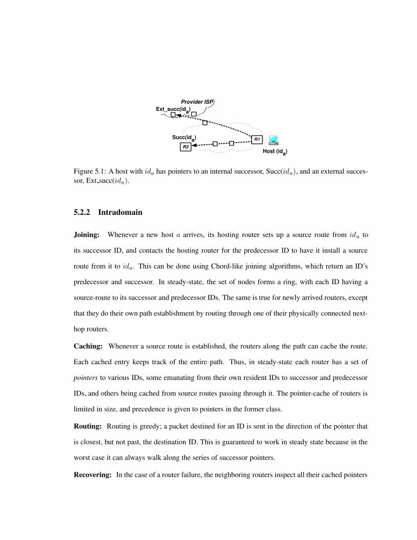
3
R1
Provider ISP
R2 Host (id a )
Succ(id a )
Ext_succ (id a )
Figure 5.1: A host with ida has pointers to an internal successor, Succ(ida), and an external succes-sor, Ext succ(ida).
5.2.2 Intradomain
Joining: Whenever a new host a arrives, its hosting router sets up a source route from ida to
its successor ID, and contacts the hosting router for the predecessor ID to have it install a source
route from it to ida. This can be done using Chord-like joining algorithms, which return an ID’s
predecessor and successor. In steady-state, the set of nodes forms a ring, with each ID having a
source-route to its successor and predecessor IDs. The same is true for newly arrived routers, except
that they do their own path establishment by routing through one of their physically connected next-
hop routers.
Caching: Whenever a source route is established, the routers along the path can cache the route.
Each cached entry keeps track of the entire path. Thus, in steady-state each router has a set of
pointers to various IDs, some emanating from their own resident IDs to successor and predecessor
IDs, and others being cached from source routes passing through it. The pointer-cache of routers is
limited in size, and precedence is given to pointers in the former class.
Routing: Routing is greedy; a packet destined for an ID is sent in the direction of the pointer that
is closest, but not past, the destination ID. This is guaranteed to work in steady state because in the
worst case it can always walk along the series of successor pointers.
Recovering: In the case of a router failure, the neighboring routers inspect all their cached pointers

and send tear-down messages along any path containing the failed router. In the case of host failure,
the router sends tear-down messages to each of the ID’s successors and predecessors. When a
tear-down message reaches a hosting router, it rejoins the relevant ID so it can find its current
successor/predecessor. To increase resilience to host failure, nodes can hold multiple successors,
e.g., the successor and its successor. We will call these successor-groups.
Finally, certain sequences of failure events could cause the successor ring to partition into
multiple pieces, even if the underlying network is connected. To prevent this, routers continuously
distribute routes to a small set of stable identifiers. Routers locally perform a correctness check
based on the contents of this set, then execute a partition-repair protocol that ensures network state
converges correctly into a single ring. This ensures that if a path exists between hosts a and b, ROFL
will ensure a and b can reach each other.
Ephemeral hosts: Ephemeral hosts are connected intermittently at a particular location, either
because of mobility or because of frequent shut-downs. For example, laptops or desktop PCs may
be expected to fail or move more often than infrastructure servers. Because of this, ephemeral hosts
cannot serve as successor or predecessor to other IDs; they merely establish a path between them-
selves and their predecessor, which keeps a source-route to the ephemeral hosts; when other nodes
route to this ephemeral ID, the packet will travel to the predecessor router, and then be forwarded to
the host. Ephemeral hosts can set up these backpointers at other routers for more efficient routing,
but state at the predecessor is necessary.
5.2.3 Interdomain
Our inter-domain design is similar in spirit to our intra-domain design, but it must be
modified to abide by AS-level policies. ROFL’s interdomain design leverages the fact [150, 151]
that most current policies can be modeled as arising out of a simple hierarchical AS graph. For
supporting such policies, we extend Canon [56] Our extensions allow ROFL to support a number of
policies commonly used in today’ Internet, including customer-provider, multihoming, backup, and

both direct and indirect peering.
Constructing a global ring: In our design, each AS X runs its own ROFL-ring (RR), RRX ,
as specified by our intra-domain design. To ensure that hosts within its RR are reachable from
other domains, RRX needs to be merged with the RRs of other domains. This is done in three
phases. First, we define the up-hierarchy graph GX for X to be all nodes above X in the graph,
including its providers, its providers’ providers, and so on. On startup, AS X discovers its up-
hierarchy GX . Edges in GX correspond to X’s view of the customer-provider, multihoming, and
peering relationships in X’s up-hierarchy. GX does not need to be complete: providers of AS X
may choose not to reveal certain links to X , or X may decide to prune GX to reduce its join and
maintenance overhead. Control overhead for joins and maintenance is roughly linear in the number
of edges in this graph.
Next, X performs a recursive merging protocol (Section 5.4.1) that constructs additional
successors to RRs in other ASes. This is done by merging X’s RR with all the RRs in the domains
at or below X in the AS graph. This is done in a manner that respects certain interdomain policies.
Moreover, the merging process provides a useful isolation property: when a host in domain X
sends a packet to a host in domain Y , the data path is guaranteed to stay within the subtree rooted
at the earliest common ancestor of these two domains. As a corollary, traffic internal to an AS stays
internal.
In addition to using successor pointers, our inter-domain design also uses proximity-based
routing tables to reduce stretch. These are routing tables that allow fast progress in the ID-space, and
are similar to Pastry routing tables: the main difference is that a routing table entry for an ID in AS
X points to the node with the appropriate prefix which resides in the lowest level of the hierarchy
relative to X . This ensures that following routing tables does not violate the isolation property.
Joining: Whenever a host with ida comes up in AS X , and wishes to be globally reachable, its
hosting router is responsible for finding a successor and predecessor at each level of the GX sub-
hierarchy. This can be done by looking up the predecessor and successor of ida at each level of

the AS hierarchy. The hosting router then associates the successor and predecessor pointers for ida
with an AS-level source-route to the routers hosting the predecessor and successor identifiers for ida.
This can be any source route consistent with the graph GX , and there can be multiple source routes
for resilience to failure. These AS-level routes are used in determining which of these pointers are
available for relaying a packet. This is done in a manner similar to how BGP determines the links
to forward a route advertisement. To reduce stretch, the hosting router uses a similar procedure to
discover fingers at each level. Border routers in an AS may optionally maintain Bloom filters that
summarize the set of hosts in the subtree rooted at the AS. These Bloom filters are also updated
during the join process.
Routing: Our mechanism for routing relies on greedy routing, augmented with in-packet AS-level
source-routes. As a packet is routed towards its destination, it is marked with an AS-level source
route denoting the path traversed until that point. When a router receives a packet, it uses the source-
route in determining the candidate set of outgoing pointers can be used in forwarding the packet; that
is, it finds the paths that are consistent with policy. This decision is made by comparing the source-
route on the packet to the source-routes on the pointers using BGP-like import and export filtering
rules. Then, greedy routing is used to determine the closest candidate pointer, whose source-route
is tacked on to the packet. Note that the salubrious properties of greedy routing such as loop-free
forwarding, eventual reachability apply even when the packet is forwarded in this fashion.
Recovering: In the case of a router failure, routers with pointers to the failed router are either
notified proactively by neighbors of the failed router, or discover the failure when forwarding a
packet. In the case of host failure, the router sends tear-down messages to each of the ID’s successors
and predecessors. When a host/router failure is noticed by a router which has pointers to the ID, it
rejoins the relevant ID by finding successors/predecessors at the relevant level.
In the case of AS-level link failures that lead to a partition in G, the isolation property
ensures that hosts in ASes X and Y can route to one another provided there is a subtree in GX ∪GY
such that all AS-level links in the subtree are functional. Hence in the common case where one

access link of a multi-homed AS goes down, incoming and outgoing traffic will be automatically
shifted to the other access links. Note however that in some failure patterns, there is a path in the
Internet graph between ASes X,Y , but no fully functional subtree in GX ∪ GY . In this case, AS
X can either prune the graph GX to only working links, and redetermine the successors of its IDs
over this graph; or, it can add working links to GX to ensure that such a working subtree exists, and
re-join its IDs over those links.
Handling Policies: Our design also handles peering and multi-homing relationships between ASes.
We treat multi-homing links as backup links; an AS joins the global ROFL ring through one of its
providers, and uses the other providers as backup, in case the primary provider fails.
Peering relationships can be handled in our design in two different ways. One design
option is to transform the graph G so that doing greedy routing over the links established via joins
in G suffices to handle peering. In this case, the property we provide is that, if a customer of provider
X routes to a customer of a peer AS Y of X , it is guaranteed to use the peering link for that purpose.
However, the limitation here is that the peering link may also be used in routing packets destined
to customers not belonging to Y ; such packets will be simply returned via the peering link, and
will be routed via X’s provider. This is necessary since it is not possible to determine whether the
destination is a customer of Y without doing a complete search of the customers of Y . Our second
design option is to use Bloom filters. In this method, AS X uses the Bloom filters of its peers to
determine if the destination is possibly a customer of any of its peers. If so, it uses the peering link
to forward the packet to Y , which uses its pointer to route to the destination. Note that to handle
false positives in the Bloom filter, this method may require back-tracking, in case the destination is
discovered to not be in Y .
Our design requires ISPs to reveal customer-provider, multi-homing, and peering relation-
ships to their down-stream customers. This may not be a serious concern, since as shown in [150],
such relationships are mostly inferable in BGP today. Finally, our design allows multi-homed ASes
some degree of control over incoming traffic on their access links, though we are yet to fully un-

derstand how this degree of freedom compares to that permitted by BGP. This control in ROFL is
achieved by investing the join process and identifiers with some traffic-engineering semantics, as
described in Section 5.5.
5.3 Intradomain
5.3.1 Host Join
Algorithm 9 The join internal(id) function is executed by a router upon receipt of a host request
for joining the network. The function bootstraps a virtual node on behalf of the host.1: authenticate(id) # exception on error
2: vn = new VirtualNode(id)
3: register virtual node(vn)
4: pred = find predecessor(id)
5: # Setup state with local participants
6: vn.successorinternal = pred.successorinternal
7: pred.successorinternal = vn
8: S = select providers()
9: for all s ∈ S do
10: br = locate border router(s)
11: p = get path to root(s)
12: br.join external(vn, p)
13: end for
The joining host with ida first selects an upstream gateway router to join the ring on its
behalf. It opens a session to the router and calls join internal (Algorithm 9), which performs the
bootstrap process. The router authenticates the host and spawns a virtual node vn(ida) that will
hold the routing state with respect to this host’s identifier. The router then joins the internal ring by
using the host’s identifier to locate the predecessor in the internal AS. The predecessor is used to
initialize the internal successor state in vn(ida). The router then discovers the external successor

state by first determining the set of paths along the up-hierarchy on which to join. This set of paths
is selected in a manner obeying the policies of the joining host and its internal AS. For each of these
paths, the router then selects a border router connected to the next AS-hop along the path. The
router forwards the join request to this router, which in turns performs an external join using the
join external function (Section 5.4.1).
However, this procedure does not work if ida is the router R’s first resident ID, since R
does not have any pointers and hence cannot make progress in the ring. To deal with this, when
R first starts up it creates a default virtual node. The default virtual node’s ID is the router-id, and
its successors act as default routes if it has no other successors that it can use to make progress.
The default virtual node joins by flooding a message containing the router-ID. The router-ID’s
predecessors add a pointer to the router-ID, and its successors respond back via the path contained
in the message. This ensures that all resident IDs find a predecessor in the internal AS when joining.
When forwarding a control message, intermediate routers may cache destination IDs con-
tained in the message if they have spare memory. The control messages also build up a list of
routers along the way, and this list is stored by the router hosting the destination ID. This list is used
to maintain consistency in the presence of host failure, as described below.
5.3.2 Failure
We aim to maintain routing state so as to preserve two invariants: (a) if there is a working
network-path between a pair of nodes (A,B), then ROFL ensures that A and B are reachable from
each other (b) if A has a pointer to B, and if either B or the path to B fails, then A will delete its
pointer.
In this section, we describing a failure recovery procedure used to preserve these invari-
ants. To simplify exposition, we divide discussion into several components, one for each type of
fail-stop failure that can occur in a wired network: router failures, host failures, and link failures.
In addition, particularly severe failures may trigger a network partition, where network-level paths

might not exist between hosts on either side of the failure. We finish this subsection by discussing
how to handle partitions.
Router failure: If a router R hosting several IDs goes down, there are two things that need
to happen. (1) Each host connected to the router R discovers the outage via a session timeout
and needs to rejoin via an alternate router. Alternatively it can do this proactively by joining via
multiple routers during its initial join. (2) There are a set of virtual nodes residing at other routers
with pointers to IDs at R that need to be updated. Although we could simply rejoin each virtual
node affected by the failure, we instead improve performance by having routers in advance agree
on a sorted list of routers that will be failed over to in event of failure. Upon node failure, the end
host and remote routers deterministically fail over to the next alive router on the list.
Host failure: When host with ID ida fails, the gateway router R will detect the failure through
a session timeout. R needs to inform all other routers with pointers to ida that it has failed. One
simple way to do this would be to flood all routers with an invalidation message. However, flooding
the entire system on host failure would not be efficient. Instead, we address this by constraining
the set of routers in the system that are allowed to maintain cached state for ida. For simplicity we
constrain this set to be routers holding predecessors of ida and routers that lie on the shortest path
to those routers. When there is a host failure, the router sends a directed flood, i.e., a source-routed
flood that traverse only this subset of routers. When shortest paths change, or links fail, routers
can optionally update this set via additional directed floods, however this is an optimization that is
not necessary for correctness. As a fallback to handle router failure, routers also monitor link-state
advertisements and delete pointers to IDs residing at unreachable routers.
Link failure, no partition: If the set of links that fail do not create a partition, then the router
need not make any changes on behalf of its resident IDs since the network map will find alternate
paths to their successors. However, the contents of pointer caches that traverse the link should be
temporarily invalidated while the link is failed to avoid sending packets over the failed link.
Link failure, partition: In the event of a network-layer partition, the successor pointers maintained
by routers need to remerge into two separate, consistent namespaces. First, pointers that terminate at
routers that are no longer reachable are torn down. Next, the router attempts to repair these pointers
locally by shifting the successors down to fill the empty space left by each failed successor. Note
the successors remaining after this operation are correct, and may be used to forward packets, since
no closer IDs may exist in the network. It then tries asking each of its successors Si starting at the
one furthest away to fill the gap at the end of its successor list. Unfortunately this process could
cause the ring to partition into multiple pieces, even if the underlying network is connected. To
recover from this, we require routers to distribute the smallest ID they know about, i.e., the zero-id,
to all its neighbors. The zero-ID a router propagates is set equal to the minimum of the smallest
ID it is hosting and the smallest ID it receives from its neighbors. The path is also distributed to
avoid circular dependencies and allow all nodes to reach the zero node. The end result is that all
routers become aware of the smallest ID in the network. This ensures multiple partitions will heal
if the network layer is connected: if the zero-ID is on one ring, its predecessor on the other ring will
learn about it and add it, triggering a merging process. The zero-ID will repair its successor and
predecessor, who in turn repair their successors, and so on until the rings are merged. In practice, the
zero node advertisements are piggybacked on link-state advertisements, and we use the router-IDs
of routers instead of the zero-ID to reduce sensitivity to churn and balance load over several routers
during the recovery phase.
5.3.3 Packet forwarding
When a router forwards a packet, it selects the closest ID it knows about to the destination
ID. This is done using the link-state database to return the next hop towards the router containing
that ID. This approach requires routers to return the closest entry in the namespace as opposed to the
shortest-prefix match lookups commonly done today. Finding the closest entry can be implemented
with minor modifications to routers that support longest-prefix match. The key observation is that,
given a list of IDs sorted in numerical order, the closest namespace distance match is either the

shortest prefix match or the one right before it in the sorted list.
Algorithm 10 The route (pkt) function is executed by a internal router upon receipt of a packet
destined for a particular virtual node.1: next hopvn = VN.best match(pkt.destination.id)
2: if pkt.destination.id == next hopvn.id then
3: deliver to host(next hopvn, pkt)
4: else
5: next hopc = PC.best match(pkt.destination.id)
6: if next hopvn.id < next hopc.id then
7: sendto(next hopc.path to router, pkt)
8: else
9: sendto(next hopvn.path to router, pkt)
10: end if
11: end if
The forwarding algorithm is shown in Algorithm 10. The router maintains a list of resident
virtual nodes (V N ), which exports a best match function that determines the next hop by choosing
the closest ID among all resident IDs and their successors that does not overshoot the destination. If
the destination is an attached host, VN.best match returns the interface for the host, which the router
uses to deliver the packet. Otherwise, next hopvn is set to the successor state of some resident
virtual node. Before forwarding the packet, the router first checks its pointer cache (PC) for an
entry that is closer to the destination than the value stored in next hopvn. If such a cached entry
exists, the router uses its value, stored in next hopc, instead.
5.4 Interdomain
In this section we describe our design for interdomain ROFL. First, we give an overview
of how the basic protocol works. Next we provide more details regarding how hosts join, how
packets are routed, and how failures are handled. Then we describe how customer-provider, peering,

Internal finger
Externalfinger
Parent
ChildChild
Figure 5.2: Merging rings
and multihoming policies are supported by our augmented greedy routing protocol over a suitably
defined Directed Acyclic Graph (DAG).
5.4.1 Basic design
Interdomain ROFL constructs a DHT over a hierarchical graph, where nodes correspond
to ASes and links correspond to inter-AS adjacencies. Within each AS, the identifiers form an
internal ring as described in Section 5.3. These rings are then merged with one another in a bottom-
up fashion, traversing up towards the root of the AS-hierarchy, by having virtual nodes maintain
routes to external successors that reside in other ASes, as shown in Figure 5.2. For a identifier ida
in ring 1, these external pointers are established to identifiers idb in ring 2 that satisfy two conditions:
(a) idb would be ida’s successor if the two rings were merged into a single ring, and (b) there are no
identifiers in either AS within the interval [ida, idb]. This approach is repeated for each level in the
hierarchy. Condition (b) thus limits the number of external pointers that are formed. Prior work has
shown that the expected total number of internal and external pointers is O(log(n)), where n is the
total number of identifiers across all stub domains [56].
Routing occurs as in Chord. Note that on a single customer-provider hierarchy, a packet
sent between a pair of ASes will traverse no higher than their least-common ancestor in that hierar-
chy. Moreover, if a host within an AS sends a packet to another host in that same AS, no external
pointers will be used. This allows ROFL to provide the following isolation property. Consider two
ASes X and Y in a single customer provider-hierarchy. Define the up-hierarchy of a node Z as the
set of all ancestors of Z in the hierarchy, including Z’s providers, Z’s providers’ providers, and so

on. Define the height h(Z,A) of some ancestor A in Z’s hierarchy to be the number of customer-
to-provider edges that must be traversed to reach A from Z along the shortest path between the
two. Note that in a single customer-provider hierarchy, there exists one and only one shortest path
between any pair of nodes. We define the Least Common Ancestor L = lca(X,Y ) to be the node
L that minimizes the sum h(X,L)+h(Y,L). Note there is only one unique least-common ancestor
in a single provider customer hierarchy. We say a routing protocol obeys the isolation property, if
for every pair of nodes (X,Y ), the number of customer-to-provider links traversed by a packet sent
from X to Y is less than the height of their least common ancestor h(X, lca(X,Y )).
Figure 5.3: Routing state for virtual node with identifier 8.
For example, Figure 5.3 shows the internal and external routing state for a router hosting
an identifier 8 residing in AS 4. The hosting router has an internal successor pointer to the router
hosting identifier 20 and external successors to hosting routers residing in ASes 5 and 3. The
join protocol discovers the external successor at each level of the joining node’s up-hierarchy. For
instance, the hosting router for 8 maintains a external successor to 16 at the level of AS 2, and an
external successor to 14 at the level of AS 1.
Next, we describe the details of interdomain ROFL. First, we describe how network state
is updated when a new host joins. Then, we present two extensions to reduce routing delay: one
based on maintaining long-distance finger pointers, and another based on using caching to exploit
reference locality. Then, we describe how failures are detected and how network state is updated
to recover from them. Finally, we describe how the interdomain algorithm given in this section

interacts with the algorithm given in the previous section for routing within a single ISP.
Joining: When a hosting router R performs a join for an end-host with ID ida, R joins both the
internal ring (as described in Section 5.3) and also the ROFL ring on behalf of ida. ida joins the
ROFL ring by, for each AS X in its up-hierarchy, routing towards its successor using links that
traverse no higher than X . In this fashion, it builds a list of candidate successors, one corresponding
to each AS in its up-hierarchy. It then removes unnecessary successors. For example in Figure 5.3,
if the identifier in AS 5 were 12 instead of 16, 8 would not maintain 14 as a successor (as doing
so could violate isolation). Finally, if ida is the first host in the ISP, it needs a way to bootstrap
itself into the ROFL ring. This is done by having host identifiers register with their providers, and
their provider’s providers, and so on when they join. Their providers may maintain a list of such
identifiers at each level of the hierarchy for resiliency purposes. This list need not be large, as
only a small number of nodes is necessary to recover from most failures. When a new host joins
that does not have a predecessor in its internal ring, the ISP will forward the join request to one of
its providers to lookup a bootstrap node. The registration process also allows operators to control
which set of ASes ida can join through, and to constrain connectivity to follow policy or traffic
engineering goals.
The join external function (Algorithm 11) shows this process in more detail. First, the
external successor at a level is discovered by routing towards the external predecessor at that level
and then pruning away any references to virtual nodes outside the current hierarchy in both the
predecessor’s and the virtual node’s routing state. After pruning, the virtual node with the minimum
identifier in the predecessor’s routing state is kept if it is a better external successor than the virtual
node’s current set of successors. The next step of the algorithm tests if the virtual node itself is a
better external successor to the predecessor, and if so adds it to the predecessor’s routing state. The
final step uses the path vector passed in as the argument to recursively call this same function at the
border router of the next provider. This recursive call terminates at the root of the hierarchy.
Exploiting network proximity: ROFL exploits network proximity to reduce routing stretch by

Algorithm 11 The join external (vn, p) function is executed by a border router upon receipt of a
request for a joining virtual node vn along the path p.1: pred = find predecessor(vn.id)
2: RSpred = pred.successorexternal ∪ pred.successorinternal
3: RSvn = vn.successorexternal ∪ vn.successorinternal
4: prune route entries(RSpred, p)
5: prune route entries(RSvn, p)
6: if min id(RSpred) < min id(RSvn) then
7: vn.successorexternal.add(min id(RSpred))
8: end if
9: if vn.id < min id(RSpred) then
10: pred.successorexternal.add(vn)
11: end if
12: br = next border router(p)
13: if br! = NULL then
14: br.join external(vn, p)
15: end if

maintaining proximity-based fingers in addition to successor pointers. That is, when selecting fin-
gers at each level of the hierarchy, ROFL tries to select fingers that are nearby in the physical net-
work. This reduces the number of network level hops required to make a given amount of progress
in the namespace.
We store these fingers in a prefix-based finger table constructed in a manner similar to the
Routing tables of Bamboo [125], Pastry [134], and Tapestry [176]. Each node in the finger table
corresponds to a given prefix-length and each column corresponds to a digit at that prefix. Each
entry contains an ID that is reachable via the smallest number of up-links. In other words, an entry
K may be inserted in the element (i, j) in J ’s finger table iff (a) K matches i bits of J ’s ID and
K’s [i, i + b] bits are equal to digit j (b) of all joined IDs L matching the position (i, j), it is not the
case that the path from J to L contains fewer up-links than the path J to K . If this table is correctly
maintained, the isolation property is preserved. To exploit proximity, entries that are reachable via
fewer AS-level hops are preferred. For correctness purposes, each ID also maintains a list of IDs
that are pointing to it.
Our joining and maintenance protocols for these fingers are adapted from the proximity
extensions in [22] to support the policies and properties described in Section 5.4.2. The join consists
of three phases. First, the joining host sends a join request towards its own ID. At each network-
level hop n, n attempts to insert entries from its own finger table into the message. The message is
then returned back to J after it reaches J ’s predecessor. At this point, J ’s entries are correct. Next,
J may need to be inserted into the finger tables of other IDs. This is done by having virtual nodes
maintain copies of their finger’s finger tables. In particular, we modify the join to also record a list
of IDs that need to insert J . J then sends a multicast message containing its ID to every virtual node
in this list. Upon receipt of this message, virtual nodes check to see if any of their fingers need to
insert J , and if so update their neighbors, and so on. Nodes also piggyback probes on data packets
to ensure this state is maintained correctly. Note if this state becomes inconsistent, isolation may be
violated, but packets will still reach their correct final destination.

Exploiting reference locality: ROFL exploits locality by using pointer-caches [195]. Routers
maintain caches in fast memory which contain frequently accessed routes. When routing a packet,
the router checks its pointer cache, and shortcuts if it observes a cached pointer is numerically closer
to the final destination. However, naive pointer-caching violates the isolation property, as an AS may
select a pointer from its cache that traverses its provider. Hence ASes that cache pointers maintain
Bloom filters containing the set of hosts joined below that AS. When receiving a packet destined
to identifier idb, the border router consults the Bloom filter to see if identifier idb is below it in the
hierarchy. If not, the router is free to use its pointer-cache to find a closer next-hop ID. The source-
route on the packet is used to determine which pointer-cache entry to use based on policy. Note
that the use of Bloom filters guarantees the isolation property in the presence of caching. Further,
the size of Bloom filters can be traded off against the false positive rate. Finally, the decision of
whether to use pointer caches can be made by each ISP in isolation. Unless otherwise mentioned, in
our simulations we assume no ISPs use interdomain pointer caches or their associated Bloom filters.
Failure recovery: The isolation property ensures that failures and instability outside of a particular
hierarchy will not influence routing within the hierarchy. Because of this, link failures can cause
partitions, which make successors at a certain level of the hierarchy unreachable, are not reacted to
immediately. Immediate reaction is not necessary because ROFL ensures that alternate paths are
available. Also, an ISP may host virtual servers on behalf of a customer ISP, which it can maintain
during that customer’s outages. Finally, in the event of long-term failures, we need to ensure that
the ring converges consistently at each level of the hierarchy. We do this using a similar approach
to that given in Section 5.3.2. In particular, each AS maintains a route to the ID closest to zero
(zero-ID) in their down-hierarchy. Hosts then merge changes to the zero-ID to ensure partitions and
other anomalous conditions such as loopy cycles [148] heal properly.
Integrating EGP and IGP routing: Today’s Internet uses iBGP to redistribute externally learned
routes internally. In our architecture, we have a similar need for a protocol to do this redistribution.
As mentioned in previous sections, packets contain a list of ISPs that can be used to reach the final

Figure 5.4: Conversion rules for (a) peering (b) multihoming and backup.
destination. Hence a router containing a packet needs to know how to reach the next-hop AS in the
list. To solve this problem, we have border routers flood their existence internally. We believe doing
this does not significantly impact performance since even the largest ISPs typically only have a few
hundred border routers. Moreover, these advertisements can be aggregated if ISPs wish to treat two
routes to the same next-hop ISP through different border routers as being equal.
5.4.2 Handling policies
We aim to support four common types of inter-ISP relationships arising from the Internet’s
hierarchical structure: provider-customer links where a customer ISP pays a provider to forward
its traffic, peering links where two ISPs forward each other’s traffic typically without exchanging
payment, backup links where an ISP forwards to its neighbor only if there is a failure along its
primary link, and multihomed connections, where an ISP may have several outgoing links. We
support policies using two conversion rules (Figure 5.4) that conceptually convert the AS hierarchy
into a single provider-customer hierarchy. These rules do not actually modify ISP relationships, but
rather are implemented as modifications to the join process.
Handling peering:
As previously mentioned, we can handle a peering relationship in two ways. In the first
option, we modify the AS relationship graph to include virtual ASes. A virtual AS is a construct
that allows ROFL to discover successors reachable via peering links. A virtual AS is not explicitly

maintained as additional state, but is implemented as an additional set of join rules. An example is
shown in Figure 5.4a. For each peering link, a virtual AS is constructed that acts as a provider for
the ASes on either side of the link, and as a customer of each AS’s provider. When virtual nodes
join, they treat links to virtual ASes as multihomed links, and join them as they would a provider. In
this fashion, a host in AS 2 will discover its successors in AS 3, however ROFL will ensure that its
join will not traverse AS 1. Note that if several ASes are all peered together in a clique, for example
as is the case for the Tier 1 ISPs, we only need a single virtual AS rather than a separate virtual AS
for each link.
In the second option, we use Bloom filters to deduce when a packet should be allowed to
traverse a peering link. When the packet is being routed via an AS, the AS can check the Bloom
filters corresponding to its peers to determine if the destination is a customer of any of them. If so,
the packet is routed over the peering link, and a bit set to indicate that it has traversed a peering link.
In this mode, the packet is not allowed to go up the hierarchy. This ensures that an AS would not
use its provider to route packets for its peer. If the destination is not found in the down hierarchy,
then it is returned over the peering link, at which point, the packet continues on its original path.
These two options have complementary advantages and disadvantages. The virtual AS
option has the disadvantage of increasing join overhead, since additional joins must be sent across
peering links, but it makes the data plane protocol simpler. The Bloom filter option has the disad-
vantage of requiring a complicated backtracking protocol, but requires no joins over peering links.
For this reason, we describe simulation results comparing both of these design options.
Handling multihoming: A multihomed ISP purchases connectivity from more than one provider
and typically has policies indicating how each access link is to be used. There are three kinds of mul-
tihomed connections: single-address multihoming, where an ISP has a single block of addresses but
is connected to multiple providers, multi-address multihoming, where an ISP has a separate block of
addresses corresponding to each multihomed connection, and single-neighbor multihoming, where
an ISP is connected with a neighboring ISP via multiple links. Multi-address multihoming is han-

dled by joining each ID via a different provider, and single-neighbor multihoming is handled by
applying policy to select which link to use to reach the neighbor. Single-address multihoming is
done by repeating the join for each member of the AS’s up-hierarchy. The up-hierarchy for an AS
consists of its providers, their providers, and so on up to the Tier-1 ISPs, plus ASes reachable across
peering links. Although repeating the join increases overhead, the up-hierarchy above a node is
typically small [169], and we can eliminate redundant lookups that terminate at the same successor
at multiple levels. Finally, backup relationships are supported by directing join requests only over
non-backup links.
5.5 Additional routing issues
We now describe preliminary extensions to the ROFL design to (a) support more flexible
routing policies and traffic engineering (b) provide improved delivery models such as anycast, mul-
ticast (c) deal with security concerns, specifically, denial-of-service attacks. The last two concerns
are meant to be illustrative examples that suggest how the clean-slate design of ROFL may provide
better-than-IP routing and security properties.
5.5.1 Routing Control
BGP and OSPF, two commonly used routing protocols today, allow the operator extremely
flexible policy and traffic engineering knobs. We discuss the flexibility of ROFL on these metrics.
Inter-domain routing control: ROFL’s policy extensions support customer-provider, backup, and
peering relationships. Although these paths may suffice for most traffic, custom paths that satisfy
high-level policy goals, stronger QoS constraints, or multipath connectivity may be desired. We pro-
pose to handle other policies and route selection mechanisms via two complementary approaches.
We propose the use of endpoint-based negotiation where we allow the source and desti-
nation nodes to negotiate the path, or set of paths, to be used for forwarding. Here, we leverage a
particular observation about the Internet hierarchy: all paths that can be used to reach AS X from

AS Y traverse ASes in the intersection of X’s and Y ’s up-hierarchies. Moreover, up-hierarchies are
typically fairly small and can be represented in just a few hundred bytes. Hence when sending the
first packet in a session, we allow the source and destination to negotiate a subset of ASes in this set
that can be used to forward packets between the two. This is done by having the destination select
a subset of ASes above it in the hierarchy and appending this set to the response.
Next, when a hosting router in a multihomed AS performs a join, it sends a join out on
each of its AS’s p providers with IDs with variable suffixes (G, xk) (1 ≤ k ≤ p). Hosts then route
packets to (G, r) where r is a randomly chosen suffix. Hosts or intermediate routers may vary r and
the suffixes xk to control the path selected for forwarding packets.
Intra-domain routing control: We can leverage our interdomain design to deal with certain
intradomain policies. For example, a transit AS that is spread over multiple countries can create
sub-rings corresponding to each of those regions. The isolation property ensures that internal traffic
will not transit costly inter-country links. Further, our inter-domain traffic engineering mechanisms
may also be used in this context to perform traffic-engineering between these regions.
5.5.2 Enhanced Delivery Services
There are a vast number of both overlay and network-level proposals for multicast and
anycast, many of which can run directly on top of the ROFL design. A few representative examples
are IP Multicast [37], Overcast [71], PIAS [8], and i3 [146]. However, traditional overlay-based
approaches don’t exploit the network layer to improve efficiency, and current network-level designs
don’t directly scale to or exploit the properties of flat-ID based routing. In this section, we describe
some simple extensions to previous approaches that enable anycast and multicast.
Anycast: Anycast is an extension of ROFL’s multihoming design. Servers belonging to group G
join with ID (G, x). A host may then route to (G, y), where y is set arbitrarily. Intermediate routers
forward the packet towards G, treating all suffixes equally. This results in the packet reaching the
first server in G for which the packet encounters a route. This style of anycast can be extended to
perform more advanced functions such as. load balancing by modifying X,Y and the size of G in
a manner similar to the approach taken in i3 [146]. This approach to anycast requires no additional
state or control message overhead beyond that of joining the network.
Multicast: A host wishing to join the multicast group G sends an anycast request towards a nearby
member of G. At each hop, the message adds a pointer corresponding to the group pointing back
along the reverse path, in a manner similar to path-painting [70]. If the message intersects a router
that is already part of the group, the packet does not traverse any further. The end result is a tree
composed of bidirectional links. A host wishing to multicast a packet P forwards the packet along
this tree. Routers forward a copy of P out all outgoing links for which there are pointers, excluding
the link on which P was received. In the case of single-source multicast, a more efficient tree can
be constructed by having nodes route towards the source.
5.5.3 Security
Today’s Internet allows any host to send any kind of traffic to any other host. This com-
munication model, although very flexible, unfortunately makes hosts particularly subject to attack.
Worms such as SQL Slammer infect hundreds of thousands of computers in minutes [106] Denial
of Service (DoS) attacks with an estimated 1.5 million attacking machines have been observed [44]
Network operators are hastily deploying intermediate solutions such as NAT and firewalls to curtail
these attacks. However, such approaches hinder the deployment of new protocols, cause layering
violations, and complicate network design.
The use of flat identifiers in the ROFL design allows us to provide stronger guarantees than
possible in the Internet today. In this section, we describe two extensions to existing mechanisms to
improve host security in ROFL. First, we describe how to limit the impact of DoS attacks by making
hosts unreachable by default. Then, we describe how to control which remote parties are allowed to
contact a host by a capability-based access control mechanism.
Default off: It has been proposed, for example in [63, 7], that in the face of mounting security

concerns, hosts should not by default be reachable from other hosts. Our architecture eases this by
ensuring hosts are only reachable from their fingers. The host, or its upstream router on its behalf,
can control pointer construction to limit which other hosts are allowed to reach it. In addition, we
require that hosts explicitly register with their providers and traffic to a host not registered with
its provider be dropped. In the worst case this traffic can be dropped at the provider of the desti-
nation AS, however the use of flat identifiers can potentially allow this traffic to be dropped even
earlier. Filtering mechanisms can also be implemented more securely by verifying that the request
for installing a filter dropping traffic to an identifier comes from the host owning that identifier.
Capabilities: The use of flat identifiers allows more fine-grained access control through the use
of capabilities. Our approach bears some similarities to TVA [170]. When a destination receives a
route setup request, it grants access according to its own policies. If permission is granted, the path
information and capability are returned to the source, which it uses to communicate further with
the destination. This permission is cryptographically secured by the self-certifying identifier of the
receiver. A capability [170] is a cryptographic token designating that a particular source with its
own unique identifier is allowed to contact the destination. Only with a proper capability will the
data plane forward the data packets. Capabilities are associated with a lifetime to defend against
sources that attempt to abuse the capability and commit a DoS attack against the destination. ROFL
also supports the use of path capabilities to further restrict communication along the AS-level path
to a destination. Path restriction allows for fine grain pushback mechanisms and hinders the ability
to conduct DDoS attacks.
5.6 Evaluation
5.6.1 Methodology
Realistically simulating the Internet is itself a highly challenging problem, both due to
scaling issues and because certain aspects of the Internet, such as ISP policies or the number of

1 10
100 1000
10000 100000 1e+06 1e+07 1e+08
1 10 100 1000 10000To
tal j
oin
over
head
[pac
kets
]
IDs per AS
ROFL-AS1221ROFL-AS1239ROFL-AS3257ROFL-AS3967
Figure 5.5: Cumulative overhead to construct the network.
0
0.2
0.4
0.6
0.8
1
0 5 10 15 20 25 30 35 40 45
Cum
ulat
ive
fract
ion
Join overhead [packets]
AS 1221AS 1239AS 3257AS 3967
Figure 5.6: CDF of overhead per node join.
0
0.2
0.4
0.6
0.8
1
0 5 10 15 20 25 30 35 40 45
Cum
ulat
ive
fract
ion
Join latency [ms]
AS 3257AS 3967AS 1239AS 1221
Figure 5.7: Join latency.

0 1 2 3 4 5 6 7 8 9
10 100 1000 10000 100000 1e+06S
tretc
h
Finger cache size [entries]
AS1221AS1239AS3257AS3967
Figure 5.8: Effect of pointer cache size on stretch.
0
0.02
0.04
0.06
0.08
0.1
0 100 200Frac
tion
of m
sgs
trave
rsin
g ro
uter
Router number
OSPFROFL
Figure 5.9: Load balance, compared with shortest-path routing (OSPF).
1
10
100
1000
10000
1 10 100 1000Avg
. rou
ter m
emor
y us
age
[ent
ries]
IDs
ROFL-AS1221ROFL-AS1239ROFL-AS3257ROFL-AS3967
Figure 5.10: Memory used per router.

links connecting ISPs are difficult to infer [153]. We conducted some highly simplified simulations
to make the evaluation tractable, yet as much as possible attempted to use real-word measurements
for topologies and parameter settings.
Intradomain: The topologies we used were collected from Rocketfuel [141], over 4 large ISPs:
AS 1221 which has 318 routers and 2.6 million hosts, AS 1239 which has 604 routers and 10
million hosts, AS 3257 which has 240 routers and 0.5 million hosts, and AS 3967 which has 201
routers and 2.1 million hosts. The number of hosts in each of these ISPs were estimated using
CAIDA skitter [180] traces. We do this by correlating the IP addresses found in the traces with
Routeviews [191] routing tables to map IP addresses onto ASes. We then normalize by the number
of estimated hosts in the Internet, which we assume to be 600 million hosts [188]. to estimate the
number of hosts per AS. Each host is assigned a 128-bit ID. Transit routers are presumed to have
9Mbits of fast memory such as TCAM that can be devoted to intradomain forwarding state. In
these experiments we fill pointer caches only with contents available from control packets. In these
results, we investigate the more challenging case where we do not snoop on data packet headers for
filling caches. We occasionally point out the overheads associated with CMU-ETHERNET [109],
an alternate approach to a similar problem. We acknowledge the authors of [109] were attempting to
provide a simplified first-cut solution to this problem rather than to achieve this level of scalability,
so we reference their work only for a baseline comparison.
Interdomain: We use the complete inter-AS topology graph sampled from Routeviews. The AS
hierarchy inference tool developed by Subramanian et al [150] was used to infer customer/provider
relationships and skitter traces were used to estimate the number of hosts per ISP. We start by
presenting results for a traditional single-threaded simulator running on a single machine. This
design did not scale up to 600 million hosts. Instead, we ran simulations for smaller networks
containing only thirty thousand hosts and present scaling trends. To evaluate performance on larger
networks, we built a distributed packet-level simulator that ran across a cluster of machines. We
scaled this simulator to 300 million hosts and measured control overhead and routing stretch for
networks of this scale. Finally, to evaluate system performance in a real-world environment, we
built and deployed an implementation that ran as an overlay network. For simplicity and lack of
sufficiently fine-grained measurements, we model each AS as a single node, and start nodes up one
at a time in random order. Unless otherwise mentioned, the results shown do not use the Bloom
filter or finger caching optimizations.
Metrics: We evaluate the join overhead, which corresponds to the number of network-level mes-
sages required to add a host to the network, the stretch, or the ratio between the traversed path and
the shortest path. For Interdomain, we consider stretch to be the ratio of the traversed path to the
path BGP would select.
5.6.2 Intradomain
This section describes results for routing within a single ISP. Here simulate ROFL on four
representative ISP topologies. We characterize performance along four key metrics: the control
overhead required to join a host, the stretch penalty incurred when routing data packets, the memory
requirements at routers, and the control overhead required to converge after failure.
Host join overhead: Figure 5.5 shows the number of messages required to join a given number
of hosts, while Figure 5.6 shows a CDF of the per-host join overhead. Like CMU-ETHERNET,
ROFL scales linearly in the number of hosts. However, CMU-ETHERNET requires between 37
and 181 times more messages to build the network. ROFL’s join overhead is roughly four messages
times the diameter of the network since only successors need to be notified on join of a new host.
Moreover, ROFL gives the operator control over the number of messages generated for host joins.
For example, ephemeral hosts can join with a smaller number of successor pointers, and routers can
keep successor groups active while host-sessions fluctuate. Figure 5.7 shows a CDF of the amount
of time required to complete a join. This amount of time is typically on the order of the network
diameter, because several messages in the join are sent in parallel. In practice, join overhead may
be reduced further by ephemeral joins and having the router maintain the virtual node when the host

fails or moves temporarily to another AS. Finally, we note this join overhead is a one-time cost in
the absence of churn.
Stretch: Figure 5.8 plots stretch, measured by routing packets between random sources and des-
tinations, as a function of the size of the pointer cache. Although stretch with small pointer caches
can be high, stretch drops to roughly 2 with a 9Mbit cache of 128-bit IDs, which can store 70,000
entries. By comparison a DNS lookup suffers a round trip to the DNS server before sending which
could incur a stretch of up to 3. Figure 5.9 shows the fraction of packets that traverse a particular
router. The x-axis corresponds to the rank of the router in a list sorted by the y-value for OSPF. That
is, for a particular x value, we plot the load at the ith most congested router in an OSPF network, and
the load under ROFL for that same router. We can see that although load varies across routers, the
difference from OSPF is fairly slight, indicating that ROFL does not introduce a significant increase
in the number of “hot-spots.”
Memory requirements: The intradomain pointer-cache memory requirements of ROFL is shown
in Figure 5.10. By comparison CMU-ETHERNET requires from 34 to 1200 times more memory
than ROFL. ROFL’s memory requirements were reduced further for routers near the network edge,
potentially allowing non-core routers such as customer routers in access networks to have smaller
TCAMs or to cache popular destinations and additional successors. In addition, hosting routers
must store state for resident IDs, which requires between 1.3 Mbits for AS 3257 to 10.5 Mbits for
AS 1239 assuming IDs are hosted at the Rocketfuel-visible transit routers.
Failure: Here we discuss the overhead and time to reconverge in the presence of network level
events. We found the overhead triggered by host failure and mobility to be comparable to join over-
head, and link/router failures that do not trigger partitions to be comparable to OSPF recovery times.
However if a network-layer partition occurs the ring needs to reconverge into two separate, consis-
tent namespaces. We believe partition events in ISPs are rare in comparison to host failures given
the high degree of engineering and redundancy in these networks. Nevertheless, we investigate this
overhead to show performance under such extreme scenarios. Figure 5.11 shows the overhead to

1
10
100
1000
10000
100000
1 10 100 1000Ove
rhea
d pe
r par
titio
n [p
acke
ts]
IDs per PoP
AS 1221AS 1239AS 3257AS 3967
Figure 5.11: Convergence overhead from Point of Presence (PoP) failures
recover from a partition. We create partitions by varying the number of IDs per PoP between 1 and
10000, randomly selecting a PoP, and measuring the overhead to disconnect and reconnect it to the
graph. We collect PoP information from Rocketfuel [141] traces.
We found that repair did not trigger any massive spikes in overhead, which was roughly
on the same order of magnitude of rejoining all the hosts in the PoP. Finally, we repeated this
experiment for 10 million partitions and our approach converged correctly in every case; we perform
consistency checks for misconverged rings in the simulator.
5.6.3 Interdomain
The previous section evaluated performance for a small-scale simulated deployment within
individual ISPs. In this section we present results for a simulated Internet-wide deployment. We
start by showing control overhead required to join a single node to the network, and the stretch
penalty incurred when forwarding packets. We then discuss the control overhead required to re-
cover from failures and the amount of memory required at border routers.
The results in this section were acquired on a traditional single-processor machine, and
hence are limited in terms of scale. We will present larger-scale simulations of up to 300 million
nodes collected on a special purpose distributed simulator which we discuss in Section 5.6.4.

0 50
100 150 200 250 300 350
1 10 100 1000 10000Jo
in o
verh
ead
[pac
kets
]
IDs
EphemeralSingle-homed
Rec. multi-homedPeering
Figure 5.12: Comparison of joining strategies.
0
0.2
0.4
0.6
0.8
1
1 2 3 4 5 6 7 8 9 10
Cum
ulat
ive
fract
ion
Stretch
ROFL 60 fingersROFL 160 fingersROFL 280 fingers
BGP-policy
Figure 5.13: Stretch.
0
0.5
1
1.5
2
2.5
0.1 1 10 100 1000 10000 100000
Stre
tch
average finger cache size [Mbits per AS]
Figure 5.14: Effect of pointer caching.
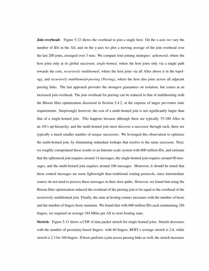
Join overhead: Figure 5.12 shows the overhead to join a single host. On the x-axis we vary the
number of IDs in the AS, and on the y-axis we plot a moving average of the join overhead over
the last 200 joins, averaged over 3 runs. We compare four joining strategies: ephemeral, where the
host joins only at its global successor, single-homed, where the host joins only via a single path
towards the core, recursively multihomed, where the host joins via all ASes above it in the topol-
ogy, and recursively multihomed+peering (Peering), where the host also joins across all adjacent
peering links. The last approach provides the strongest guarantees on isolation, but comes at an
increased join overhead. The join overhead for peering can be reduced to that of multihoming with
the Bloom filter optimization discussed in Section 5.4.2, at the expense of larger per-router state
requirements. Surprisingly however, the cost of a multi-homed join is not significantly larger than
that of a single-homed join. This happens because although there are typically 75-100 ASes in
an AS’s up-hierarchy, and the multi-homed join must discover a successor through each, there are
typically a much smaller number of unique successors. We leveraged this observation to optimize
the multi-homed join, by eliminating redundant lookups that resolve to the same successor. Next,
we roughly extrapolated these results to an Internet-scale system with 600 million IDs, and estimate
that the ephemeral join requires around 14 messages, the single-homed join requires around 80 mes-
sages, and the multi-homed join requires around 100 messages. Moreover, it should be noted that
these control messages are more lightweight than traditional routing protocols, since intermediate
routers do not need to process these messages in their slow-paths. However, we found that using the
Bloom filter optimization reduced the overhead of the peering join to be equal to the overhead of the
recursively multihomed join. Finally, the state at hosting routers increases with the number of hosts
and the number of fingers hosts maintain. We found that with 600 million IDs each maintaining 256
fingers, we required on average 184 Mbits per AS to store hosting state.
Stretch: Figure 5.13 shows a CDF of data packet stretch for single-homed joins. Stretch decreases
with the number of proximity-based fingers: with 60 fingers, ROFL’s average stretch is 2.8, while
stretch is 2.3 for 160 fingers. If hosts perform a join across peering links as well, the stretch increases
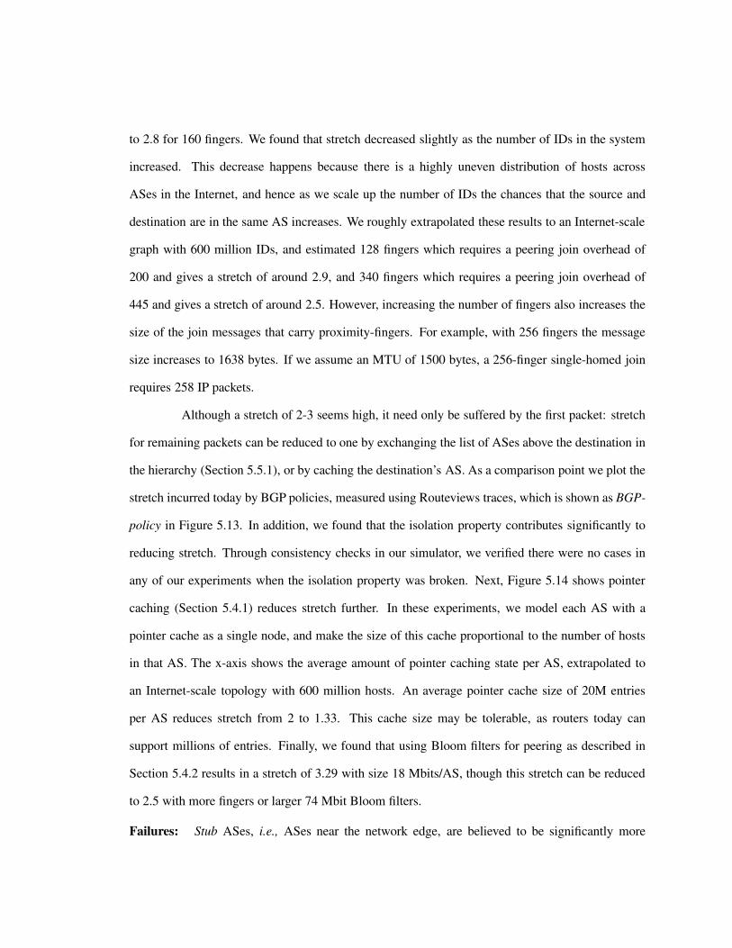
to 2.8 for 160 fingers. We found that stretch decreased slightly as the number of IDs in the system
increased. This decrease happens because there is a highly uneven distribution of hosts across
ASes in the Internet, and hence as we scale up the number of IDs the chances that the source and
destination are in the same AS increases. We roughly extrapolated these results to an Internet-scale
graph with 600 million IDs, and estimated 128 fingers which requires a peering join overhead of
200 and gives a stretch of around 2.9, and 340 fingers which requires a peering join overhead of
445 and gives a stretch of around 2.5. However, increasing the number of fingers also increases the
size of the join messages that carry proximity-fingers. For example, with 256 fingers the message
size increases to 1638 bytes. If we assume an MTU of 1500 bytes, a 256-finger single-homed join
requires 258 IP packets.
Although a stretch of 2-3 seems high, it need only be suffered by the first packet: stretch
for remaining packets can be reduced to one by exchanging the list of ASes above the destination in
the hierarchy (Section 5.5.1), or by caching the destination’s AS. As a comparison point we plot the
stretch incurred today by BGP policies, measured using Routeviews traces, which is shown as BGP-
policy in Figure 5.13. In addition, we found that the isolation property contributes significantly to
reducing stretch. Through consistency checks in our simulator, we verified there were no cases in
any of our experiments when the isolation property was broken. Next, Figure 5.14 shows pointer
caching (Section 5.4.1) reduces stretch further. In these experiments, we model each AS with a
pointer cache as a single node, and make the size of this cache proportional to the number of hosts
in that AS. The x-axis shows the average amount of pointer caching state per AS, extrapolated to
an Internet-scale topology with 600 million hosts. An average pointer cache size of 20M entries
per AS reduces stretch from 2 to 1.33. This cache size may be tolerable, as routers today can
support millions of entries. Finally, we found that using Bloom filters for peering as described in
Section 5.4.2 results in a stretch of 3.29 with size 18 Mbits/AS, though this stretch can be reduced
to 2.5 with more fingers or larger 74 Mbit Bloom filters.
Failures: Stub ASes, i.e., ASes near the network edge, are believed to be significantly more
unstable than ISPs near the core [45]. In this experiment we fail randomly selected stub ASes and
measure two metrics. First, we measure the number of paths affected by the failure. We found
on average 99.998% of Internet paths were unaffected by the failure, indicating that the effects of
failures were well contained. Next, we found that ROFL required on average 4950 messages to
repair successors after a stub AS failure, which roughly corresponds to the number of identifiers
hosted in the failed stub AS.
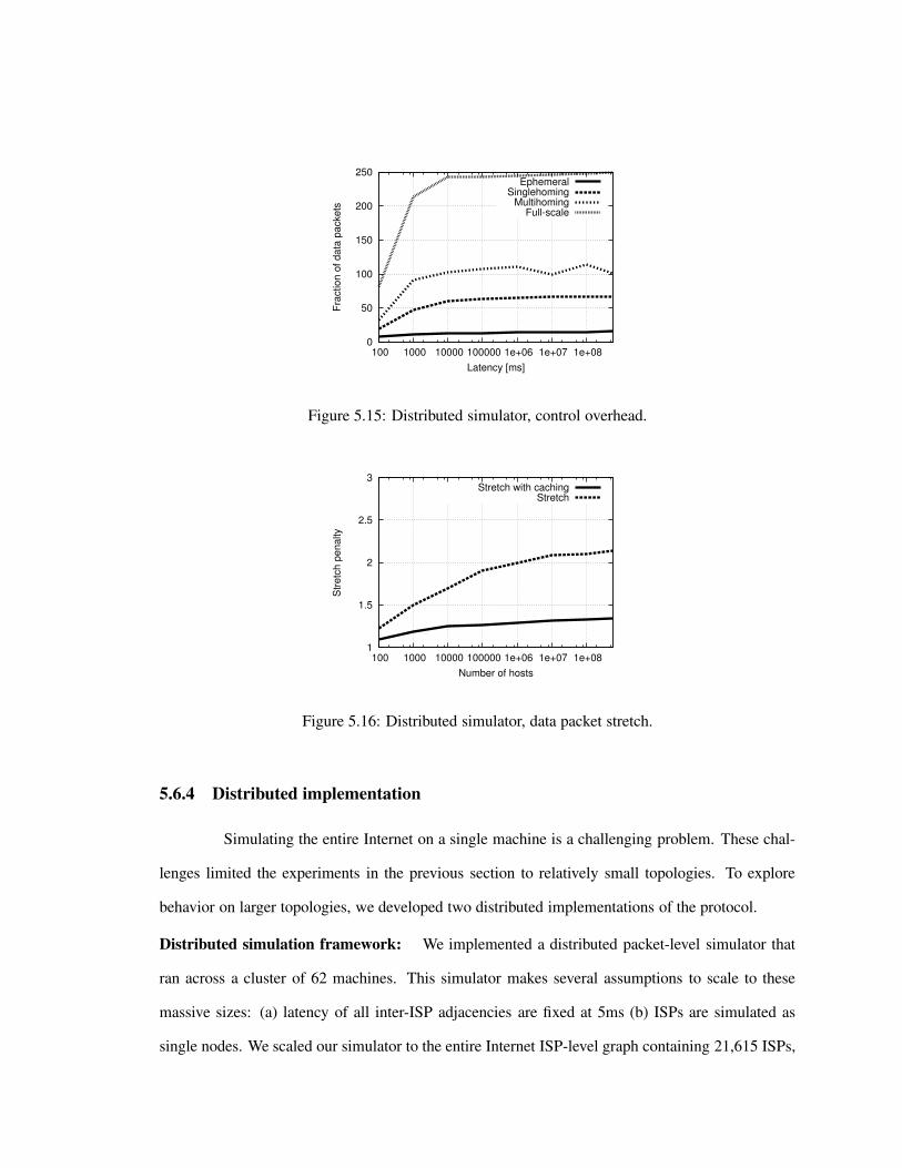
0
50
100
150
200
250
100 1000 10000 100000 1e+06 1e+07 1e+08
Frac
tion
of d
ata
pack
ets
Latency [ms]
EphemeralSinglehoming
MultihomingFull-scale
Figure 5.15: Distributed simulator, control overhead.
1
1.5
2
2.5
3
100 1000 10000 100000 1e+06 1e+07 1e+08
Stre
tch
pena
lty
Number of hosts
Stretch with cachingStretch
Figure 5.16: Distributed simulator, data packet stretch.
5.6.4 Distributed implementation
Simulating the entire Internet on a single machine is a challenging problem. These chal-
lenges limited the experiments in the previous section to relatively small topologies. To explore
behavior on larger topologies, we developed two distributed implementations of the protocol.
Distributed simulation framework: We implemented a distributed packet-level simulator that
ran across a cluster of 62 machines. This simulator makes several assumptions to scale to these
massive sizes: (a) latency of all inter-ISP adjacencies are fixed at 5ms (b) ISPs are simulated as
single nodes. We scaled our simulator to the entire Internet ISP-level graph containing 21,615 ISPs,

44,902 inter-ISP adjacencies, and 300 million hosts.
Figure 5.15 shows control overhead for each of the joining strategies discussed in the
previous section. Here, we infer host distributions across ISPs from CAIDA Skitter traces [180].
Along the x-axis we increase the number of hosts participating in the protocol, and along the y-
axis we measure the control overhead required to join a single host. Each data point represents an
average over the last 100 joins.
We can see that in a network with 300 million hosts, we require roughly 250 messages to
join an additional host on average. We are able to reduce this overhead further by sacrificing policy
flexibility. For example with a singlehoming join, which joins up a single branch to the root, the
host requires 75 messages. With an ephemeral join, where a host registers with the host’s global
successor, 12 messages are required.
However, Figure 5.16 shows the delay penalty of the protocol is large at Internet scales.
Here we route data packets between random source-destination pairs and measure the stretch, or
the ratio of the path length traversed by the packet to the underlying shortest path length. Here
the x-axis is again the number of hosts in the network, and the y-axis is the stretch. In a network
with 300 million hosts, the average stretch penalty incurred by packets is a factor of 2.2. However,
by using the proximity-based finger caching strategy discussed in Section 5.4, the stretch penalty
decreases to a factor of 1.4. This stretch may be tolerable, as the stretch penalty incurred by BGP is
a factor of 1.5, though we note that our stretch penalty of 1.4 would be in addition to this. Also, we
found that by caching popular routes, i.e., fingers that transit the greatest amount of traffic, we were
able to reduce this stretch even further to 1.02.
Deployment on Planetlab: It is not necessary to deploy ROFL at the network layer to realize
its benefits. ROFL may be deployed as an overlay network, where a collection of servers provide
mappings between IP addresses and persistent identifiers. This approach allows us to attain the
benefits of policy-safety and consistency without requiring deployment at the network layer.
With this motivation, we developed an overlay-based implementation of ROFL, and de-
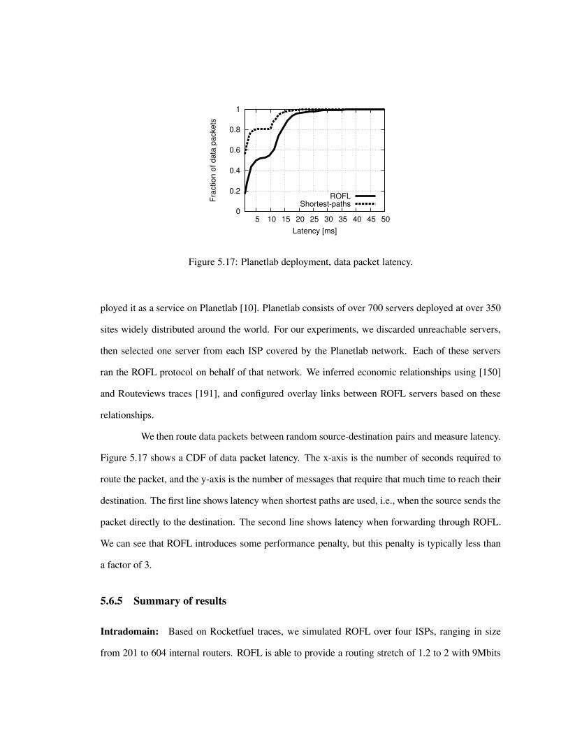
0
0.2
0.4
0.6
0.8
1
5 10 15 20 25 30 35 40 45 50Fr
actio
n of
dat
a pa
cket
s
Latency [ms]
ROFLShortest-paths
Figure 5.17: Planetlab deployment, data packet latency.
ployed it as a service on Planetlab [10]. Planetlab consists of over 700 servers deployed at over 350
sites widely distributed around the world. For our experiments, we discarded unreachable servers,
then selected one server from each ISP covered by the Planetlab network. Each of these servers
ran the ROFL protocol on behalf of that network. We inferred economic relationships using [150]
and Routeviews traces [191], and configured overlay links between ROFL servers based on these
relationships.
We then route data packets between random source-destination pairs and measure latency.
Figure 5.17 shows a CDF of data packet latency. The x-axis is the number of seconds required to
route the packet, and the y-axis is the number of messages that require that much time to reach their
destination. The first line shows latency when shortest paths are used, i.e., when the source sends the
packet directly to the destination. The second line shows latency when forwarding through ROFL.
We can see that ROFL introduces some performance penalty, but this penalty is typically less than
a factor of 3.
5.6.5 Summary of results
Intradomain: Based on Rocketfuel traces, we simulated ROFL over four ISPs, ranging in size
from 201 to 604 internal routers. ROFL is able to provide a routing stretch of 1.2 to 2 with 9Mbits

of pointer cache, with reasonable load balance across routers. Hosts typically complete joining
in less than 40ms, with less than 45 control messages generated per host. ROFL correctly heals
from partitions, host failures, and host mobility with control overhead roughly that of rejoining the
affected hosts.
Interdomain: We extrapolated our simulation results over the AS graph to the Internet scale system
with 600 million hosts, and estimated that a ROFL host can join across all providers and peers and
acquire 340 fingers with ˜445 control messages. This overhead can be reduced for unstable hosts
by performing a single-homed join to ˜75 messages, or an ephemeral join to ˜14 messages. The
host can route packets in a manner that respects several inter-AS policies, with an average stretch of
2.5. This stretch may be reduced to 2.1 by roughly doubling the number of fingers. By maintaining
pointer caches at border routers, this stretch may be reduced further, to 1.33 with on average 20
million entries of caching space per AS. Finally, ASes may reduce join overhead by leveraging
Bloom filters to eliminate joins across peering links. This reduces join overhead to ˜100 messages,
but requires 74 Mbits of Bloom filter state per AS.
5.7 Summary and thesis roadmap
In this chapter we presented ROFL, a collection of extensions to Identity-based Routing
(IBR) that allow it to perform Internet routing. We started the chapter by presenting our overall
architecture, and describing the functions that routers perform. Our design has two main parts: a
collection of intradomain protocols, that allow routes to be constructed within a single ISP, and
several interdomain protocols, which establish routes across ISPs. We presented the details of these
protocols and the properties they provide, and then presented results from simulations and an im-
plementation. The results indicate that the protocol scales to Internet sizes, and provides support for
several common Internet routing policies.
So far in this thesis we have discussed the details of the IBR protocol, and evaluation
studies in the context of both wireless networks and the Internet. In the next chapter we will present

a short summary of the key results and contributions in this thesis. We will then conclude with a
discussion of several avenues of future work and open problems.
139
Chapter 6
Conclusions and Future Work
This thesis described the first scalable network-level algorithm for routing on identities
in computer networks. This section concludes the dissertation by summarizing contributions and
suggesting avenues for future work.
6.1 Contributions
It is accepted wisdom that today’s network architectures conflate network addressing with
host identities, but there has been little agreement on how to separate the two. In this thesis we pro-
pose to address this quandary by routing directly on host identities themselves, and eliminating the
need for network-layer protocols to include any mention of network location. Towards this end, we
present the first practical identity-based routing protocol, which we call IBR. We present implemen-
tations and simulations in both wired and wireless networks, and show the protocol performs well
in each of these environments.
In the context of wireless routing, we implemented and deployed IBR in a sensornet
testbed. Results from this implementation demonstrate the protocol performs well even when faced
with the drastic bandwidth and memory constraints present in sensornet environments. To study
performance in 802.11 networks, we implemented the protocol in the ns-2 network simulation [192].

Here, we found IBR outperforms several traditional ad-hoc routing protocols. In addition, we study
performance in a special-purpose simulator, to evaluate behavior under massive scales. Here, we
find IBR scales to large networks, and performs well on a variety of network topologies.
In the context of Internet routing, we derive several extensions to IBR that allow it to
handle routing policies. We also developed a proximity-based caching strategy that allows IBR to
scale to Internet sizes. To evaluate performance at Internet scales, we developed a parallel simulation
environment that leverages traces to realistically model Internet behavior. From this evaluation,
we found that IBR scales to Internet topologies while supporting several commonly used Internet
routing policies. To study performance under more realistic environments, we implemented IBR as
an overlay network and deployed it across a few hundred hosts distributed across the Internet. From
this study, we found that IBR handled churn and operation under real-world operating conditions.
6.2 Key results
Based on empirical evaluation and theoretical analysis, we arrive at several concluding
results about identity-based routing.
Correctness: We started by developing several maintenance algorithms to maintain routing state
in a consistent fashion. We then defined a reachability criterion that characterizes the property of
reliable communication in the presence of fail-stop failures. Through analysis, we showed IBR
eventually converges to provide this reachability criterion in arbitrary connected networks where
symmetric network-level paths exist between nodes. In cases where the network is partitioned, IBR
provides the reachability property within each partition. We show this convergence process takes
no more than O(n4) steps after an arbitrary number of simultaneous failures occur. We verified the
correctness of our design by instrumenting our several deployed implementations with consistency
checks.
Scalability: To evaluate the scaling properties of our protocol, we implemented our design in the
context of a wireless sensornet consisting of mica2dot motes. Mica2dot motes have limited radio

bandwidth of 19.2kbps, and limited memory capacity of 4KB. We found that even in the presence
of these resource constraints, IBR scales to a moderate-sized sensornet of 67 motes. Next, we
developed a large-scale simulation tool that allowed us to evaluate the protocol at Internet scales.
We also developed several enhancements to the design to leverage proximity when deciding which
routes to cache. From simulations and an overlay-based implementation, we found the protocol
scales to Internet sizes without requiring excessive memory or control overhead.
Routing efficiency: To evaluate the quality of routes provided by IBR, we leveraged both im-
plementations an evaluations. In the context of wireless sensornets, we found that the use of flat
identifiers allow IBR to converge quickly after failures, and make IBR more resilient to network
congestion. In addition, IBR does not required scoped flooding to correctly deliver data packets,
reducing transmission overhead.
Unfortunately, IBR incurs a stretch penalty to achieve its scalability and efficiency prop-
erties. However, this stretch penalty was low in several environments. In Internet-scale simulations,
stretch was roughly 2.2, but could be reduced to 1.4 when proximity-based caching was used. In
the context of wireless 802.11 simulations, stretch was roughly 1.3 on average. In the Planetlab
deployment, IBR incurred roughly a 5% increase in packet latency.
6.3 Future work
There is a wide spectrum of issues from the realms of both system evaluation and theoret-
ical analysis that one could pursue based on this thesis work. Here, we list four specific items that
may be interesting to investigate as future directions.
Data-centric storage: Data retrieval mechanisms for wireless sensornets typically operate by
identifying the name of the data, rather than the location where the data is stored. We believe IBR’s
DHT interface provides natural support for routing queries to stored data. In particular, a piece
of data may be consistently hashed to the closest sensornet mote in the IBR ring. One primary
challenge arises in that if a sensornet node fails, its objects must be migrated to the next-closest

node among the ring, which may be very far away across the network. To address this problem, we
propose having a sensornet mote run replica virtual nodes at neighboring nodes. When the mote
fails, these replica motes service queries from the location nearby the original object. Open ques-
tions to be investigated include the number of replicas, and how they should be placed, to reduce
update costs and maximize resilience to failures. A secondary question is to investigate how well
IBR can support applications, and how it can be tuned to maximize this particular application’s per-
formance. In addition, it may be interesting to investigate other sensornet applications, for example
providing support for aggregate queries, or detection/tracking applications. Finally, for applications
with stronger consistency properties, it would be useful to investigate the feasibility of building a
version of IBR with atomic consistency.
Theory-based analysis: This thesis has focused primarily on experimental evaluation of IBR. It
would be desirable to build up a stronger theoretical framework to explain and understand IBR’s
performance. For example, this thesis has proposed a ring-structured namespace, but this is not
a fundamental requirement. Any overlay structure that allows progress to be made along some
numerical metric would make a working substitution. One question that then arises is to characterize
the tradeoffs involved in different overlay structures. Also, given that wireless and wired networks
may differ substantially in terms of topology, it would be desirable to derive the optimal overlay
structure for a given network level structure. It would be desirable to derive tighter bounds on stretch
and state, and to understand how network topology affects these metrics. It may be also useful to
study how this work falls in respect to the compact routing literature, and to determine if compact
routing techniques may be used to refine performance of IBR. Finally, it may be interesting to build
a bounded-stretch version of IBR. This may be possible by extending the Canon [56] protocol to
non-hierarchical graphs, as Canon forwarding provides bounds on stretch.
New Internet architectures: The Internet is suffering a relentless inflation of routing update loads
that shows no signs of slowing. Worse still, recent measurement studies show that this inflation is
exceeding the capabilities of Moore’s law, requiring nonlinear cost increases in router hardware to

keep up. Hence todays architectural requirement of maintaining a complete table of all destina-
tion prefixes is quickly becoming impossible, especially in the presence of increased demands for
deaggregation and the larger address spaces of IPv6. It may be possible to develop a more scalable
network architecture based on this thesis that does not require a complete table. Instead of routing
on flat host identifiers, we treat each subnet prefix as a numeric identifier. Routers may then self-
organize and route between subnets by making progress in the prefix space towards the destination
subnet. This approach retains several benefits of flat identifiers, yet has several deployability advan-
tages. In addition, it may be interesting to investigate application of IBR to route to data objects in
the Internet as opposed to hosts. This is a much more challenging problem, as the number of data
objects in the Internet is much larger than the number of hosts. In addition, unlike hosts, it may be
desirable to access objects using a different lookup model [86], or to perform database-style queries
over objects in the network.
Security: There has been substantial work on securing DHTs. However, by moving the DHT
“down the stack,” we force it to deal with a wide variety of failure modes and misbehavior that
the IP layer masks for traditional DHTs. Traditional DHT security mechanisms do not solve this
problem, because that work assumes the IP layer behaves properly. There are several problems
that need to be solved. A taxonomy of attacks against IBR must be determined. For example, in
a path-retention attack, a malicious node may ignore teardown messages. By accumulating many
paths, many nodes will end up using it as a next-hop, allowing it to interfere with more traffic. In
a partition-induction attack, a malicious node may artificially attempt to make its virtual neighbor
set wrap around in the namespace by responding to queries in an invalid way, triggering an overlay
partition.
Then, countermeasures to these attacks must be constructed. As a starting point, one
could consider using a path-intersection check. The idea here is that each node n virtual neighbor
set should only maintain pointers to the nodes in the range (n−r/2, n+r/2). We can exploit this by
having each node perform a check when routing a path setup message: if it has a path to s/2 nodes

that lie closer in the namespace than the setup message’s destination, then the path is not allowed to
be set up. One can also use a probabilistic version of this technique based on the observation that a
pair of nodes are unlikely to be virtual neighbors if the namespace-distance between their identifiers
is particularly large. Simulations or analytical evaluation of how well these techniques can limit
attacks needs to be done. Finally, it would be desirable to determine whether it is possible to build
a Byzantine-robust version of IBR.
6.3.1 Thesis summary
The use of location-based addressing in today’s Internet introduces a number of problems.
It complicates network configuration, as human operators must allocate and manage blocks of ad-
dresses, and it requires operation and maintenance of a secondary resolution system like DNS. It
makes authentication/attribution hard, since it is hard to link actions observed in the network with a
host identifier. It makes it hard to provide different levels of priority/precedence, as access controls
and policies that give different flows priority must be managed based in a very nonintuitive fashion
on IP addresses, and must be adjusted as addresses change.
These problems seem fundamental to any network that uses location-based addressing.
To address these problems, this thesis contributes the first scalable network-level routing protocol
for location-independent identifiers. We defined operations to create and maintain sufficient state
at routers to allow any pair of nodes to communicate. Through analysis, we found the protocol
eventually converges to a correct state in the presence of fail-stop failures. Furthermore, the protocol
is practical. Through implementations, we demonstrated low stretch, low churn, and high delivery
rates over a variety of wireless and wired deployments.
However, this thesis represents only a first step in this direction. There remains a vast
amount of work yet to be done. It may be useful to investigate the feasibility of alternative delivery
models such as content routing or storage in identity-based routing protocols. More performance
evaluation over a wider range of parameters and deployment contexts must be done. In addition,

analytical models of protocol behavior would be desirable.

146
Bibliography
[1] W. Adjie-Winoto, W. Schwartz, H. Balakrishnan, J. Lilley, “The design and implementation of
an intentional naming system,” SOSP, December 1999.
[2] D. Aguayo, J. Bicket, S. Biswas, G. Judd, R. Morris, “Link-level measurements from an
802.11b mesh network, ” SIGCOMM, August 2004.
[3] T. Anderson, T. Roscoe, D. Wetherall, “Preventing Internet denial-of-service with capabilities,”
SIGCOMM Comput. Commun. Rev., 34(1):39–44, 2004.
[4] A. Arora, E. Erin, R. Ramnath, W. Leal, “Kansei: a high fidelity sensing testbed,” IEEE Internet
Computing, March 2006.
[5] H. Balakrishnan, K. Lakshminarayanan, S. Ratnasamy, S. Shenker, I. Stoica, M. Walfish, “A
layered naming architecture for the Internet,” ACM SIGCOMM, August 2004.
[6] H. Balakrishnan, M. Kaashoek, D. Karger, R. Morris, “Looking up data in p2p systems, ”
Communications of the ACM, February 2003.
[7] H. Ballani, Y. Chawathe, S. Ratnasamy, T. Roscoe, and S. Shenker, “‘Off by Default!”, Hot
Nets, 2005.
[8] H. Ballani, P. Francis. ”Towards a Global IP Anycast Service,” ACM SIGCOMM, Philadelphia,
PA, Aug 2005

[9] G. Ballintijn, M. van Steen, A. Tanenbaum, “Scalable user-friendly resource names,” IEEE
Internet Computing, 2001.
[10] S. Banerjee, T. Griffin, M. Pias, “The interdomain connectivity of PlanetLab nodes,” Passive
and Active Measurement Workshop, April 2004.
[11] A. Basu, C. Ong, A. Rasala, F. Shepherd, G. Wilfong, “Route oscillations in I-BGP with route
reflection” in Proc. of SIGCOMM, Pittsburgh, PA, August 2002.
[12] T. Berners-Lee, L. Masinter, M. McCahill, “Uniform Resource Locators (URL),” IETF, RFC
1738, December 1994.
[13] B. Bloom, “Space/time trade-offs in hash coding with allowable errors,” Commun. ACM, vol .
13, no. 7, pp. 422-426, July 1970.
[14] V. Bono, “7007 explanation and apology,” http://www.merit.edu/mail.
archives/nanog/1997-04/msg00444.html
[15] B. Braden, T. Faber, M. Handley, “From protocol stack to protocol heap - Role-Based Archi-
tecture,” Hotnets-I, October 2002.
[16] J. Broch, D. Maltz, D. Johnson, Y. Hu, J. Jetcheva, “A performance comparison of multi-hop
wireless ad hoc network routing protocols,” MobiCom, Dallas, Texas, October 1998.
[17] N. Brownlee, k claffy, E. Nemeth, “DNS measurements at a root server,” Globecom, Novem-
ber 2001.
[18] R. Callon, “Use of OSI IS-IS for routing in TCP/IP and dual environments,” IETF RFC 1195,
December 1990.
[19] K. Calvert, J. Griffioen, S. Wen, “Lightweight network support for scalable end-to-end ser-
vices,” SIGCOMM, August 2002.

[20] I. Castineyra, N. Chiappa, M. Steenstrup, “The Nimrod routing architecture, ” IETF RFC
1992, August 1996.
[21] M. Castro, P. Druschel, A. Ganesh, A. Rowstron, D. Wallach, “Secure routing for structured
peer-to-peer overlay networks,” In Proc. of OSDI, Boston, Massachusetts, December 2002.
[22] M. Castro, P. Druschel, Y. Hu, A. Rowstron, “Exploiting network proximity in peer-to-peer
overlay networks,” Technical report MSR-TR-2002-82, Microsoft Research, 2002.
[23] M. Castro, P. Druschel, A-M. Kermarrec, A. Rowstron, “SCRIBE: A large-scale and decen-
tralised application-level multicast infrastructure,” IEEE Journal on Selected Areas in Commu-
nication (JSAC), Vol. 20, No. 8, October 2002.
[24] V. Cerf, S. Burleigh, A. Hooke, L. Torgerson, R. Durst, K. Scott, K. Fall, H. Weiss, “Delay-
tolerant network architecture,” IETF Internet draft draft-irtf-dtnrg-arch-03.txt.
[25] F. Chabaud, A. Joux, “Differential collisions in SHA-0,” CRYPTO, August 1998
[26] B. Chen, K. Jamieson, H. Balakrishnan, R. Morris, “Span: an energy-efficient coordination
algorithm for topology maintenance in ad hoc wireless networks,” ACM Wireless Networks,
September 2002, vol.8, no. 5.
[27] B. Chen, R. Morris, “L+: scalable landmark routing and address lookup for multi-hop wireless
networks,” technical report, MIT-LCS-TR-837, March 2002.
[28] D. Cheriton, M. Gritter, “TRIAD: a scalable deployable NAT-based Internet architecture,”
Technical report, January 2000.
[29] D. Clark, R. Braden, A. Falk, V. Pingali, “FARA: reorganizing the addressing architecture,”
SIGCOMM FDNA Workshop, August 2003.
[30] D. Clark, C. Partridge, R. Braden, B. Davie, S. Floyd, V. Jacobson, D. Katabi, G. Minshall, K.

Ramakrishnan, T. Roscoe, I. Stoica, J. Wroclawski, L. Zhang, “Making the world (of commu-
nications) a different place,” Computer Communication Review, 2005.
[31] T. Clausen, P. Jacquet, “Optimized Link State Routing Protocol (OLSR),” IETF RFC 3626,
October 2003.
[32] R. Cox, A. Muthitacharoen, R. Morris, “Serving DNS using Chord,” IPTPS, March 2002.
[33] M. Crawford, A. Mankin, T. Narten, J. Stewart, L. Zhang, “Separating Identifiers and Locators
in Addresses,” IETF, Internet Draft, draft-ietf-ipngwg-esd-analysis-04.txt.
[34] J. Crowcroft, S. Hand, R. Mortier, T. Roscoe, A. Warfield, “Plutarch: an argument for network
pluralism,” FDNA, August 2003.
[35] S. Czerwinski, B. Zhao, T. Hodes, A. Joseph, R. Katz, “An architecture for a secure service
discovery service, ” MobiCom, August 1999.
[36] F. Dabek, M. Kaashoek, D. Karger, R. Morris, I. Stoica, “Wide-area cooperative storage with
CFS,” SOSP, October 2001.
[37] S. Deering, D. Cheriton. ”Multicast Routing in Datagram Internetworks and Extended LANs,”
ACM TOCS, 1990.
[38] F. Delmastro, “From Pastry to CrossROAD: Cross-layer ring overlay for ad-hoc networks,”
PerCom Workshops, March 2005.
[39] J. Douceur, “The sybil attack,” IPTPS, March 2002.
[40] M O’Donnell, “A proposal to separate Internet handles from names,” February 2003.
httP;//people.cs.uchicago.edu/\˜odonnell/Citizen/Network_
Identifiers/
[41] D. Eastlake, “Domain name system security extensions,” IETF, RFC 2535, March 1999.

[42] C. Ee, S. Ratnasay, S. Shenker, “Practical data-centric storage,” NSDI, May 2006.
[43] J. Eriksson, M. Faloutsos, S. Krishnamurthy, “Peernet: pushing peer-to-peer down the stack,”
IPTPS, February 2003.
[44] J. Evers, “‘Bot herders’ may have controlled 1.5 million PCs,” CNET News, Octo-
ber 2005. http://news.com.com/Bot+herders+may+have+controlled+1.5+
million+PCs/2100-7350_3-5906896.html
[45] A. Feldmann, O. Maennel, Z. Mao, A. Berger, B. Maggs, “Locating Internet routing instabili-
ties,” ACM SIGCOMM, August 2004.
[46] S. Floyd, V. Jacobson, “The synchronization of periodic routing messages,” IEEE/ACM Trans-
actions on Networking, vol. 2, no. 2, pp. 122–136, April 1994.
[47] R. Fonseca, S. Ratnasamy, J. Zhao, C. Ee, D. Culler, S. Shenker, I. Stoica, “Beacon vector
routing: scalable point-to-point routing in wireless sensor networks,” NSDI 2005.
[48] B. Ford, “Unmanaged internet protocol: taming the edge network management crisis,” Hot-
Nets, Cambridge, MA, Nov. 2003.
[49] B. Ford, J. Strauss, C. Lesniewski-Laas, S. Rhea, M. Kaashoek, R. Morris, “Persistent personal
names for globally connected mobile devices,” OSDI, November 2006.
[50] P. Francis, “Comparison of geographical and provider-rooted Internet addressing,” Proceed-
ings of INET’94, June 1994.
[51] P. Francis, R. Govindan, “Flexible routing and addressing for a next generation IP,” Computer
Communications Review, October 1994.
[52] P. Francis, R. Gummadi, “IPNL: a NAT-extended Internet architecture,” ACM SIGCOMM,
August 2002.
[53] M. Freedman, E. Freudenthal, D. Mazieres, “Democratizing content publication with Coral, ”
NSDI, March 2004.
[54] V. Fuller, T. Li, J. Yu, K. Varadhan, “Classless Inter-Domain Routing: an Address Assignment
and Aggregation Strategy,” IETF, RFC 1519, September 1993.
[55] “Internet Protocol,” IETF, RFC 791, September 1981.
[56] P. Ganesan, K. Gummadi, H. Garcia-Molina, “Canon in G major: designing DHTs with hier-
archical structure,” ICDCS, March 2004.
[57] D. Gay, P. Levis, R. von Behren, M. Welsh, E. Brewer, D. Culler, “The nesC language: a
holistic approach to networked embedded systems,” PLDI, June 2003.
[58] M. Gerla, X. Hong, G. Pei, “Fisheye state routing protocol (FSR) for ad hoc networks”,
Internet-draft, draft-ietf-manet-fsr-03.txt, June 2002.
[59] T. Griffin, F. Shepherd, G. Wilfong, “Policy disputes in path-vector protocols, ” ICNP, Novem-
ber 1999
[60] T. Griffin, G. Wilfong, “On the correctness of iBGP configuration,” SIGCOMM, August 2002.
[61] M. Gritter and D. Cheriton, “An architecture for content routing support in the Internet”, In
the USENIX Symposium on Internet Technologies and Systems, March 2001.
[62] Z. J. Haas, M. R. Pearlman, “The zone routing protocol (ZRP) for ad hoc networks,” Internet-
draft, draft-ietf-manet-zone-zrp-04.txt, July 2002.
[63] M. Handley and A. Greenhalgh, “Steps towards a DoS-resistant internet architecture”, FDNA,
2004.
[64] C. Hedrick, “Routing information protocol,” IETF RFC 1058, June 1988.

[65] E. Hoffman, k claffy, “Address administration in IPv6,” September 1996. http://www.
caida.org/publications/papers/1996/aai6/aai6.html
[66] Y. Hu. A. Perrig, D. Johnson, “Ariadne: a secure on-demand routing protocol for ad-hoc
networks,” Mobicom, Atlanta, Georgia, September 2002.
[67] Y. Hu, H. Pucha, S. Das, “Exploiting the synergy between peer-to-peer and mobile ad-hoc
networks,” Hot-OS IX, Lihue, Kauai, Hawaii, May 2003
[68] A. Iwata, C. Chiang, G. Pei, M. Gerla, T. Chen, “Scalable routing strategies for ad-hoc wireless
networks,” IEEE Journal on Selected Areas in Communications, vol. 17, no. 8, pp. 1369-1379,
August 1999.
[69] C. Intanagonwiwat, R. Govindan, D. Estrin, “Directed diffusion: a scalable and robust com-
munication paradigm for sensor networks,” Mobicom, Boston, Massachusetts, August 2000.
[70] J. Jannotti, “Network layer support for overlay networks,” PhD thesis, MIT, August 2002.
[71] J. Jannotti, D. K. Gifford, K. L. Johnson, M. F. Kaashoek, J. W. O’Toole Jr, ”Overcast: Reliable
Multicasting with an Overlay Network,” OSDI, 2000/
[72] P. Jokela, P. Nikander, J. Melen, J. Ylitalo, J. Wall, “Host identity protocol - extended abstract,”
in
[73] D. Johnson, D. Maltz, “Dynamic source routing in ad hoc wireless networks,” in Ad Hoc
Networking, edited by C. Perkins, Chapter 5, pg 139-172, Addison-Wesley, 2001.
[74] P. Johansson, T Larsson, N. Hendman, B. Mielczarek, M. Degermark. “Scenario-based perfor-
mance analysis of routing protocols for mobile ad-hoc networks”. In Proc. of Mobicom. Seattle,
Washington, 1999.
[75] A. Jonsson, M. Folke, B. Ahlgren, “The split naming/forwarding network architecture,” Proc.
Swedish National Computer Networking Workshop (SNCNW), September 2003. Wireless World
Research Forum, February 2004.
[76] D. Joseph, J. Kannan, A. Kubota, K. Lakshminarayanan, I. Stoica, K. Wehrle, “OCALA: an
architecture for supporting legacy applications over overlays,” NSDI, May 2006.
[77] H. Kaur, S. Kalyanaraman, A. Weiss, S. Kanwar, A. Gandhi, “BANANAS: an evolutionary
framework for explicit and multipath routing in the Internet,” FDNA, August 2003.
[78] B. Karp and H. Kung. “Greedy perimeter stateless routing for wireless networks,”. Mobicom,
August 2000.
[79] S. Keshav, “Naming, addressing and forwarding reconsidered,” August 2005. http://
blizzard.cs.uwaterloo.ca/keshav/home/Papers/data/05/naming.pdf
[80] S. Keshav, “Why cell phones will dominate the future internet,” Computer Communication
Review, April 2005.
[81] C. Kim, J. Rexford “Revisiting ethernet: plug-and-play made scalable and efficient,” IEEE
LANMAN, August 2007.
[82] C. Kim, J. Rexford “Reconciling zero-conf with efficiency in enterprises,” Poster, CoNext
student workshop, December 2006.
[83] J. Kim, G. Stuber, I. Akyildiz, B. Chung, “Soft handoff analysis of hierarchical CDMA cellular
systems, ” IEEE/ACM Transactions on Vehicular Technology, May 2005.
[84] S. Kim, R. Fonseca, P. Dutta, A. Tavakoli, D. Culler, P. Levis, S. Shenker, I. Stoica, “Flush: a
reliable bulk transport protocol for multihop wireless networks,” SenSys, November 2007.
[85] T. Koponen, A. Gurtov, P. Nikander, “Application mobility with Host Identity Protocol,” Ex-
tended Abstract in Proc. of NDSS Wireless and Mobile Security Workshop, February 2005.
[86] T. Koponen, M. Chawla, B.-G. Chun, A. Ermolinskiy, K.-H. Kim, “A data-oriented (and be-
yond) network architecture,” SIGCOMM, August 2007.
[87] D. Kotz, C. Newport, R. Gray, J. Liu, Y. Yuan, C. Elliott, “Experimental evaluation of wireless
simulation anomalies,” MSWiM, October 2004.
[88] B. Khorashadi, A. Chen, D. Ghosal, C-N. Chuah, M. Zhang, “Impact of transmission power
on the performance of UDP in vehicular ad hoc networks,” ICC, June 2007
[89] D. Krioukov, kc claffy, “Toward compact interdomain routing,” Unpublished draft, http:
//www.krioukov.net/˜dima/pub/cir.pdf
[90] D. Krioukov, K. Fall, X. Yang, “Compact routing on Internet-like graphs,” IEEE Infocom ,
March 2004.
[91] J. Kunze, “Functional recommendations for Internet resource locators,” IETF, RFC 1736,
February 1995.
[92] K. Lakshminarayanan, D. Adkins, A. Perrig, I. Stoica, “Securing user-controlled routing in-
frastructures,” IEEE/ACM Transactions on Networking, August 2007.
[93] H. Lee, A. Cerpa, P. Levis, “Improving wireless simulation through noise modeling,” IPSN,
April 2007.
[94] M. Leopold, M. Dydensborg, P. Bonnet, “Bluetooth and sensor networks: a reality check,”
SenSys, November 2003.
[95] P. Levis, N. Patel, D. Culler, S. Shenker, “Trickle: a self-regulating algorithm for code propa-
gation and maintenance in wireless sensor networks,” NSDI, March 2004.
[96] L. Levitin, M. Karpovsky, M. Mustafa, “A new algorithm for finding minimal cycle-breaking
sets of turns in a graph,” Journal of Graph Algorithms and Applications, 2006.
[97] J. Li, J. Jannotti, D. De Couto, D. Karger, R. Morris, “A scalable location service for geo-
graphic ad-hoc routing,” Mobicom, August 2000.
[98] T. Li, “Router scalability and Moore’s law,” Workshop on Routing and Addressing, Internet
Architecture Board, October 2006.
[99] K. Lui, K. Nahrstedt, “Topology aggregation and routing in bandwidth-delay sensitive net-
works,” IEEE Globecom, San Francisco, California, November-December 2000.
[100] N. Lynch, Distributed algorithms, Morgan Kaufmann, 1996.
[101] S. Madden, M. Franklin, J. Hellerstein, W. Hong, “The design of an acquisitional query
processing system for sensor networks,” ACM SIGMOD, June 2003.
[102] R. Mahajan, M. Castro, A. Rowstron, “Controlling the cost of reliability in peer-to-peer over-
lays,” IPTPS, February 2003.
[103] R. Mahajan, D. Wetherall, T. Anderson, “Understanding BGP misconfiguration,” SIG-
COMM, August 2002.
[104] D. Mazieres, “Self-certifying file system”, PhD thesis, MIT, May 2000.
[105] P. Mockapetris, “Domain names: concepts and facilities,” November 1987.
[106] D. Moore, V. Paxson, S. Savage, C. Shannon, S. Staniford, N. Weaver, “Inside the Slammer
worm,” IEEE Security and Privacy, July 2003.
[107] K. Moore, “Things that NATs break,” June 2004. http://www.cs.utk.edu/
\˜moore/opinions/what-nats-break.html
[108] J. Moy, “OSPF: Anatomy of an Internet routing protocol, ” Addison-Wesley, January 1998.
[109] A. Myers, E. Ng, H. Zhang, “Rethinking the service model: scaling ethernet to a million
nodes,” HotNets, November 2004.

[110] A. Nandan, S. Das, G. Pau, M. Gerla, M. Sanadidi, “Cooperative downloading in vehicular
ad-hoc wireless networks,” IEEE WONS, January 2005.
[111] P. Nikander, J. Ylitalo, J. Wall, “Integrating security, mobility, and multi-homing in a HIP
way,” NDSS, February 2003.
[112] M. O’Dell, “GSE - an alternate addressing architecture for IPv6”,
ftp://ds.internic.net/internet-drafts/draftietf-ipngwg-gseaddr-00.txt, 1997.
[113] V. Pappas, Z. Xu, S. Lu, D. Massey, A. Terzis, L. Zhang, “Impact of configuration errors on
DNS robustness,” SIGCOMM, August 2004.
[114] K. Park, V. Pai, L. Peterson, Z. Wang, “CoDNS: improving DNS performance and reliability
via cooperative lookups,” OSDI, December 2004.
[115] V. Park, M. Corson, “Temporally-ordered routing algorithm (TORA) version 1: functional
specification,” Internet-draft, draft-ietf-manet-tora-spec-04.txt, July 2001.
[116] C. Perkins, K. Luo, “Using DHCP with computers that move,” Wireless networks, vol. 1, no.
3, 1995.
[117] G. Pei, M. Gerla, X. Hong, “LANMAR: Landmark routing for large scale wireless ad-hoc
networks with group mobility,” Mobihoc, August 2000.
[118] C. Perkins, E. Royer, “Ad hoc on-demand distance vector routing,” Mobile Computing Sys-
tems and Applications, New Orleans, Louisiana, February 1999, pg 90-100.
[119] C. Perkins, P. Bhagwat, “Highly dynamic destination-sequenced distance-vector routing
(DSDV) for mobile computers,” in Proceedings of SIGCOMM’94, August-September 1994,
pg 234-244.
[120] R. Perlman, “Interconnections: bridges and routers, ” Addison-Wesley, 1992.

[121] L. Peterson, S. Shenker, J. Turner, “Overcoming the Internet impasse through virtualization,”
HotNets, November 2004.
[122] D. Pei, M. Azuma, D. Massey, L. Zhang, “BGP-RCN: improving BGP convergence through
root cause notification,” Computer Networks 48(2):175-194, August 2006.
[123] V. Ramasubramanian, E. Sirer, “The design and implementation of a next generation name
service for the Internet,” SIGCOMM, August 2004.
[124] V. Ramasubramanian, Z. Haas, E. Sirer, “SHARP: A hybrid adaptive routing protocol for
mobile ad hoc networks,” Mobihoc, June 2003.
[125] S. Rhea, B. Godfrey, B. Karp, J. Kubiatowicz, S. Ratnasamy, S. Shenker, I. Stoica, H. Yu,
“OpenDHT: A public DHT service and its uses,” SIGCOMM, August 2005.
[126] R. Rivest, “The MD5 message-digest algorithm,” IETF, RFC 1321, April 1992.
[127] A. Rao, S. Ratnasamy, C. Papadimitriou, S. Shenker, I. Stoica, “Geographic routing without
location information,” Mobicom, September 2003.
[128] S. Ratnasamy, “Capturing complexity in networked systems design: the case for improved
metrics, ” HotNets-V, November 2006.
[129] S. Ratnasamy, P. Francis, M. Handley, R. Karp, S. Shenker, “A scalable content-addressable
network” In Proc. of ACM SIGCOMM, San Diego, California, August 2001.
[130] S. Ratnasamy, B. Karp, S. Shenker, D. Estrin, R. Govindan, L. Yin, F. Yu, “Data-centric
storage in sensornets with GHT, a geographic hash table,” WSNA, June 2002.
[131] S. Ratnasamy, S. Shenker, S. McCanne, “Towards an evolvable Internet architecture,” SIG-
COMM, August 2005.

[132] M. Roussopoulos, P. Maniatis, E. Swierk, K. Lai, G. Appenzeller, M. Baker, “Person-level
routing in the mobile people architecture,” USENIX Symposium on Internet Technologies and
Systems, October 1999.
[133] T. Roscoe, S. Hand, R. Isaacs, R. Mortier, P. Jardetzky, “Predicate routing: enabling con-
trolled networking,” October 2002.
[134] A. Rowstron and P. Druschel, “Pastry: Scalable, distributed object location and routing for
large-scale peer-to-peer systems,” In Proc. IFIP/ACM Middleware 2001, Heidelberg, Germany,
November 2001.
[135] J. Saltzer, “On the naming and binding of network destinations,” RFC 1498, August 1993.
[136] T. Salonidis, P. Bhagwat, L. Tassiulas, R. LaMaire, “Distributed topology construction of
bluetooth personal area networks,” Infocom, April 2001.
[137] B. Schwartz, A. Jackson, W. Strayer, W. Zhou, R. Rockwell, C. Partridge, “Smart packets:
applying active networks to network management,” ACM Transactions on Computer Systems,
February 2000.
[138] R. Sivakumar, P. Sinha, V. Bharghavan, “CEDAR: a core-extraction distributed ad hoc routing
algorithm,” IEEE INFOCOM, March 1999, pg 202-209
[139] K. Sollins, “Architectural principles of uniform resource name resolution,” IETF, RFC 2276,
January 1998.
[140] K. Sollins, L. Masinter, “Functional requirements for Uniform Resource Names,” IETF, RFC
1737, December 1994.
[141] N. Spring, R. Mahajan, D. Wetherall, “Measuring ISP topologies with Rocketfuel,” ACM
SIGCOMM, August 2002.
[142] P. Srisuresh, K. Egevang, “Traditional IP network address translator (Traditional NAT),”
IETF, RFC 3022, January 2001.
[143] J. Stribling, J. Li, I. Councill, M. Kaashoek, R. Morris, “OverCite: a distributed, cooperative
CiteSeer,” NSDI, May 2006.
[144] J. Stewart, “BGP4: Inter-Domain routing in the Internet,” Addison-Wesley, December 1998.
[145] I. Stoica, R. Morris, D. Karger, M. Kaashoek, H. Balakrishnan, “Chord: A scalable peer-
to-peer lookup service for Internet applications,” In Proc. of ACM SIGCOMM, San Diego,
California, August 2001.
[146] I. Stoica, D. Adkins, S. Zhuang, S. Shenker, S. Surana, “Internet indirection infrastructure,”
ACM SIGCOMM, August 2002.
[147] I. Stoica, R. Morris, D. Lieben-Nowell, D. Karger, M. Kaashoek, F. Dabek, H. Balakrishnan,
“Chord: a scalable peer-to-peer lookup protocol for Internet applications,” IEEE Transactions
on Networks, 11(1) 17-32, 2003.
[148] I. Stoica, R. Morris, D. Karger, M. F. Kaashoek, and H. Balakrishnan. “Chord: A scalable
peer-to-peer lookup service for Internet applications”. Technical Report TR-819, MIT, March
2001.
[149] L. Subramanian, “Decentralized security mechanisms for routing protocols, ” PhD thesis,
UC Berkeley, December 2005.
[150] L. Subramanian, S. Agarwal, J. Rexford, R. Katz,“Characterizing the Internet Hierarchy from
Multiple Vantage Points,” in IEEE Infocom 2002, June 2002.
[151] L. Subramanian, M. Caesar, C. Ee, M. Handley, Z. Mao, S. Shenker, I. Stoica, “HLP: a
next-generation interdomain routing protocol,” ACM SIGCOMM, August 2005.
[152] D. Tennenhouse, J. Smith, D. Sincoskie, D. Wetherall, G. Minden, “A survey of active net-
work research,” IEEE Communications Magazine, 1997.
[153] R. Teixeira, K. Marzullo, S. Savage, G. Voelker, “In search of path diversity in ISP networks,”
Internet Measurement Conference, October 2003.
[154] C. Tschudin, R. Gold, “Network pointers,” Hotnets-I, October 2002.
[155] Z. Turanyi, A. Valko, A. Campbell, “IPv4+4: an architecture for evolving the Internet address
space nack towards transparency,” ACM SIGCOMM Computer Communications Review, June
2003.
[156] A. Vadhat, M. Dahlin, T. Anderson, A. Aggarwal, “Active names: flexible location and trans-
port of wide-area resources,” USENIX Symposium on Internet Technology and Systems, Octo-
ber 1999.
[157] R. Vedantham, S. Kakamanu, S. Lakshmanan, R. Sivakumar, “Component based channel
assignment in single radio, multi-channel ad hoc networks,” MOBICOM, September 2006.
[158] S. Vegesna, “IP quality of service (Cisco networking fundamentals),” Cisco Press, January
2001.
[159] A. Viana, M. de Amorim, S. Fdida, J. Rezende, “Indirect routing using distributed location
information,” PerCom, 2003
[160] C. Villamizar, R. Chandra, R. Govindan, “BGP Route Flap Damping,” RFC 2439, November
1998.
[161] M. Vutukuru, N. Feamster, M. Walfish, H. Balakrishnan, S. Shenker, “Revisiting Internet
Addressing: Back to the Future,” technical report, MIT-CSAIL-TR-2006-025, April 2006.
[162] M. Walfish, H. Balakrishnan, S. Shenker, “Untangling the web from DNS,” NSDI March
2004.

[163] M. Walfish, J. Stribling, M. Krohn, H. Balakrishnan, R. Morris, S. Shenker, “Middleboxes
no longer considered harmful,” USENIX OSDI, December 2004.
[164] F. Wang, L. Gao, “Inferring and characterizing Internet routing policies,” Proc. Internet Mea-
surement Conference, October 2003.
[165] L. Wang, D. Massey, K. Patel, L. Zhang, “FRTR: a scalable mechanism for global routing
table consistency,” DSN, June 2004.
[166] A. Woo, T. Tong, D. Culler, “Taming the underlying challenges of reliable multihop routing
in sensor networks,” SenSys, November 2003.
[167] J. Wroclawski, “The MetaNet: white paper - workshop on research directions for the next
generation Internet,” http://www.cra.org/Policy/NGI/papers/wroklawWP
[168] Abraham Yaar, Adrian Perrig, Dawn Song, “Pi: A Path Identification Mechanism to Defend
against DDoS Attacks”, IEEE Symposium on Security and Privacy, 2003.
[169] X. Yang, “NIRA: a new Internet routing architecture,” SIGCOMM Workshop on Future Di-
rections in Network Architecture (FDNA), August 2003.
[170] X. Yang, D. Wetherall, and T. Anderson, “A DoS-limiting Network Architecture”, ACM
SIGCOMM 2005, Philadelphia, PA, August 2005.
[171] Y. Ofek, B. Yener, M. Yung, “Concurrent asynchronous broadcast on the MetaNet,” IEEE
Transactions on Computers, Vol. 46, No. 7, pages 737-749, July 1997.
[172] H. Yan, D. Maltz, T. Ng., H. Gogineni, H. Zhang, Z. Cai, “Tesseract: a 4D network control
plane,” NSDI, April 2007.
[173] T. Zahn, J. Schiller, “MADPastry: A DHT substrate for practicably sized MANETs,” ASWN,
June 2005.
[174] L. Zhang, “An overview of multihoming and open issues in GSE,” IETF Journal, 2006.

[175] B. Zhao, J. Kubiatowicz, A. Joseph, “Tapestry: an infrastructure for fault-resilient wide-area
location and routing,” Technical report UCB//CSD-01-1141, U.C. Berkeley, April 2001.
[176] B. Zhao, L. Huang, J. Stribling, S. Rhea, A. Joseph, J. Kubiatowicz, “Tapestry: a resilient
global-scale overlay for service deployment, ” IEEE Journal on Selected Areas in Communica-
tions, vol. 22, no. 1, pp. 41-53, January 2004.
[177] X. Zhao, D. Pei, L. Wang, D. Massey, A. Mankin, S. Wu, L. Zhang, “An analysis of BGP
multiple origin AS (MOAS) conflicts, ” Internet Measurement Workshop, November 2001.
[178] L. Zhou, R. van Renesse, “P6P: a peer-to-peer approach to Internet infrastructure,” IPTPS,
February 2004.
[179] D. Zhu, M. Gritter, D. Cheriton, “Feedback-based routing,” Hotnets, October 2002.
[180] CAIDA, “Skitter,” http://www.caida.org/tools/measurement/skitter
[181] Cisco Systems, Inc., “Introduction to EIGRP,” http://www.cisco.com/warp/
public/103/1.html
[182] “FIND: future Internet network design,” http://find.isi.edu, December 2005.
[183] “GENI: global environment for network innovations,” http://www.geni.net
[184] “Internet Assigned Numbers Authority (IANA) Home Page,” http://www.iana.org
[185] “ICANN - Internet Corporation for Assigned Names and Numbers,” http://www.
icann.org
[186] International DOI Foundation. http://www.doi.org
[187] “Banish those wall warts with power over ethernet,” Electronic Design, October 2003.
http://www.elecdesign.com/Articles/Index.cfm?AD=1&ArticleID=
5945&pg=3

[188] Internet Systems Consortium, “Domain survey host count,” http://www.isc.org/
index.pl?/ops/ds/, July 2005.
[189] “MICA2DOT data sheet,” www.xbow.com/Products/Product_pdf_files/
Wireless_pdf/MICA2DOT_Datasheet.pdf
[190] ‘NewArch project: future-generation Internet architecture,‘’ http://www.isi.edu/
newarch/
[191] “Route Views Project,” http://www.routeviews.org.
[192] ns-2 network simulator, http://www.isi.edu/nsnam/ns/
[193] TinyOS, software, http://www.tinyos.net
[194] Internet Systems Consortium, “Domain survey host count,” http://www.isc.org/
index.pl?/ops/ds/
[195] M. Caesar, M. Castro, E. Nightingale, G. O’Shea, A. Rowstron, “Virtual ring routing: net-
work routing inspired by DHTs,” SIGCOMM, September 2006.
[196] M. Caesar, T. Condie, J. Kannan, K. Lakshminarayanan, I. Stoica, S. Shenker, “ROFL: rout-
ing on flat labels,” SIGCOMM, September 2006.
[197] M. Caesar, J. Rexford, “BGP routing policies in ISP networks,” IEEE Network Magazine,
November 2005.
[198] Wikipedia, “Ad hoc protocol list,” http://www.wikipedia.org/wiki/Ad_hoc_
protocol_list
[199] Wikipedia, “Erdos-Renyi model,” http://en.wikipedia.org/wiki/Erd\%C5\
%91s-R\%C3\%A9nyi_model

[200] Wikipedia, “Wireless mesh network,” http://en.wikipedia.org/wiki/
Wireless_mesh
[201] Wikipedia, “Global Positioning System,” http://en.wikipedia.org/wiki/
Global_Positioning_System