Matt Statzer Mike Zauberman 17 March 2003 - Virginia Techmason/Mason_f/FlyWing03.pdf · Mike...
28
1 Flying Wing Flying Wing Matt Matt Statzer Statzer Bryan Williams Bryan Williams Mike Mike Zauberman Zauberman 17 March 2003 17 March 2003 http://www.geocities.com/witewings/bwb/gallerydetail-1-6.html http://www.bugimus.com/stealth/stealth.html http://www.nurflugel.com/Nurflugel/Northrop/n-1m/n1m_refurbished_1.jpg
-
Upload
truongkhanh -
Category
Documents
-
view
215 -
download
1
Transcript of Matt Statzer Mike Zauberman 17 March 2003 - Virginia Techmason/Mason_f/FlyWing03.pdf · Mike...

1
Flying WingFlying Wing
MattMatt StatzerStatzer
Bryan WilliamsBryan Williams
MikeMike ZaubermanZauberman
17 March 200317 March 2003
http://www.geocities.com/witewings/bwb/gallerydetail-1-6.html
http://www.bugimus.com/stealth/stealth.html
http://www.nurflugel.com/Nurflugel/Northrop/n-1m/n1m_refurbished_1.jpg
2
Flying Wing:
“….A type of airplane in which all of the functions ofa satisfactory flying machine are disposed andaccommodated within the outline of the airfoil itself.”
- Jack Northrop
What is a flying wing?What is a flying wing?

3
AerodynamicsAerodynamics
Pros:Pros:
- Reduced minimum drag due toelimination of empennageassembly
- Elimination of wing-tail vortex andshock interactions
- Greater efficiency from eliminationof non-lift producing surfaces
- Elliptic span loading is easilyachieved through wing camberand twist
- Lower trim drag using unstableconfiguration
Cons:Cons:
- Low CLmax requires high angle ofattack at takeoff and landing
- Low CLmax requires lower wingloading if takeoff conditionsgovern W/S
- Significant increase in induceddrag when washout is used forstability
- Thick wing sections create highdrag at transonic speeds
Matt

4
Drag ReductionDrag Reduction
•• CdCd min of XB-35 = 0.012 min of XB-35 = 0.012
•• CdCd min of C-5 = 0.023 min of C-5 = 0.023
•• Flying at same speed, all-wingFlying at same speed, all-wing
design can fly 13-33% fartherdesign can fly 13-33% farther
with 11-25% less powerwith 11-25% less power
•• At optimal speed for all-wingAt optimal speed for all-wing
design, flying wing will fly 7-19%design, flying wing will fly 7-19%
faster and 14-41% fartherfaster and 14-41% farther
• 33% reduction in WettedArea
• Results in reduced drag
Drag Comparison (XB-35 , C-5)Wetted Area Comparison
Reference 4
Bryan/Matt

5
Stability and ControlStability and Control
Pros:Pros:
-- Can get a higher Can get a higher CLmaxCLmax from fromrelaxed static stabilityrelaxed static stability
Cons:Cons:
-- Decreased weather-cock stabilityDecreased weather-cock stabilitymakes precision flying difficultmakes precision flying difficult
-- Larger/more control surfacesLarger/more control surfacesneeded for pitch control due toneeded for pitch control due tosmaller moment armsmaller moment arm
-- Coupling of lateral-directionalCoupling of lateral-directionalcontrols complicates controlcontrols complicates control
-- Control coupling causes non-Control coupling causes non-conventional spin recoveryconventional spin recovery
-- Induced tumble difficult to recover,Induced tumble difficult to recover,
but not encountered in normalbut not encountered in normalflightflight
Bryan

6
StructuresStructures
Pros:Pros:
- Can put a spar through the entirewidth of the plane
- Simpler to build as a single unit
- Better internal weight distribution
- Higher thickness to chord ratio tofit passengers and cargo
- Bending moment on the order of _conventional value
- Fewer 90° joints require fewerstructural members
- Lighter than conventional fuselageaircraft
Cons:Cons:
-- Difficult to pressurize cabinDifficult to pressurize cabin
-- Difficulty in evacuation ofDifficulty in evacuation of
passengers in an emergencypassengers in an emergency
Reference 4.
Mike
7
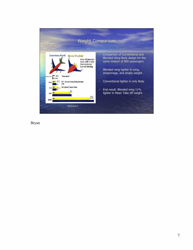
Weight ComparisonWeight Comparison
-- Comparison of Conventional andComparison of Conventional andBlended Wing Body design for theBlended Wing Body design for thesame mission of 800 passengerssame mission of 800 passengers
-- Blended wing lighter in wing,Blended wing lighter in wing,empennage, and empty weight.empennage, and empty weight.
-- Conventional lighter in only BodyConventional lighter in only Body
-- End result: Blended wing 11%End result: Blended wing 11%lighter in Mean Take off weightlighter in Mean Take off weight
Reference 4
Bryan
8
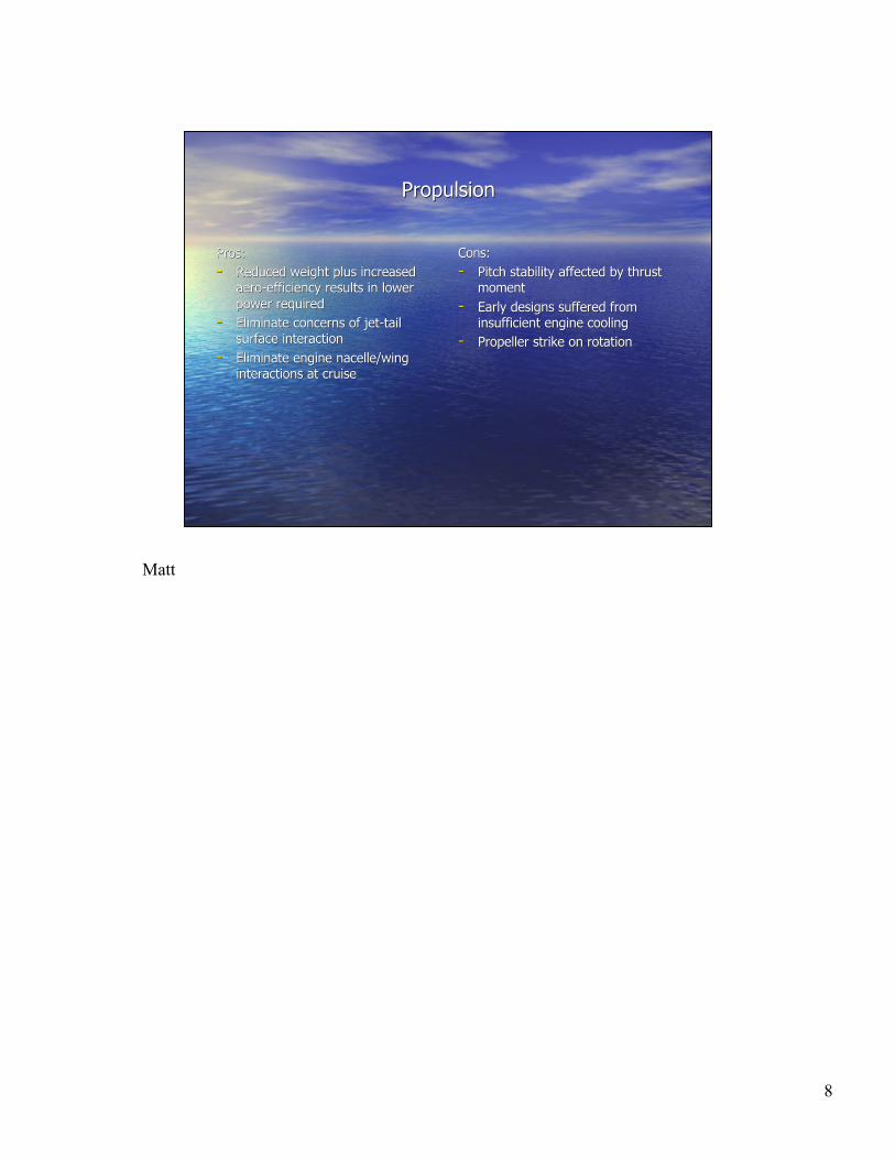
PropulsionPropulsion
Pros:Pros:
-- Reduced weight plus increasedReduced weight plus increasedaero-efficiency results in loweraero-efficiency results in lower
power requiredpower required
-- Eliminate concerns of jet-tailEliminate concerns of jet-tailsurface interactionsurface interaction
-- Eliminate engine nacelle/wingEliminate engine nacelle/winginteractions at cruiseinteractions at cruise
Cons:Cons:
-- Pitch stability affected by thrustPitch stability affected by thrustmomentmoment
-- Early designs suffered fromEarly designs suffered frominsufficient engine coolinginsufficient engine cooling
-- Propeller strike on rotationPropeller strike on rotation
Matt

9
StealthStealth
Pros:Pros:
-- Low cross sectional profileLow cross sectional profile
-- Few round shapes to allow radarFew round shapes to allow radar
to bounce backto bounce back
-- No vertical tail to reflect radarNo vertical tail to reflect radar
waveswaves
Cons:Cons:
-- Weather conditions affect stealthWeather conditions affect stealth
-- Large exposed area during bankedLarge exposed area during banked
turnturn
Mike
10
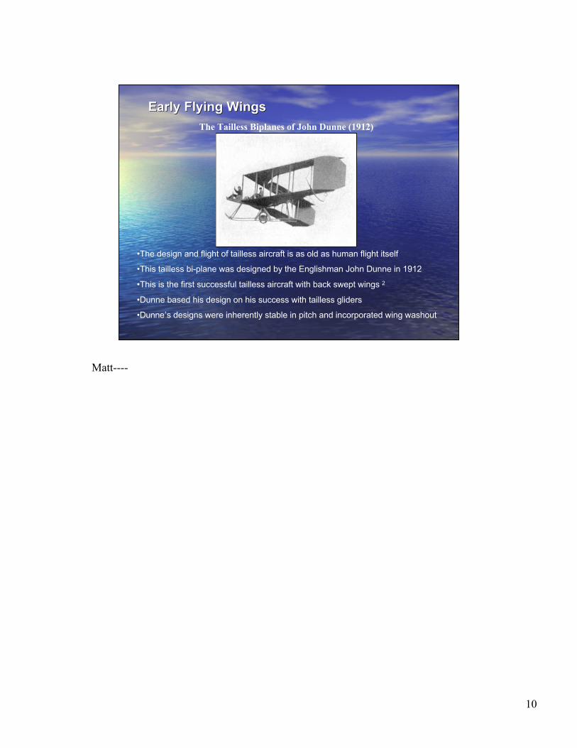
Early Flying WingsEarly Flying Wings
http://www.rcooper.0catch.com/edunne.htm
•The design and flight of tailless aircraft is as old as human flight itself
•This tailless bi-plane was designed by the Englishman John Dunne in 1912
•This is the first successful tailless aircraft with back swept wings 2
•Dunne based his design on his success with tailless gliders
•Dunne’s designs were inherently stable in pitch and incorporated wing washout
The Tailless Biplanes of John Dunne (1912)
Matt----

11
The German ContributionThe German Contribution
The German Ho V (1937)
http://aerostories.free.fr/constructeurs/horten/ho5_01.jpg
•The German brothers Walter and Reimen Horten contributed significantly to
the development of the flying wing configuration as we know it today
•The Horten brothers worked on flying wings from 1931 until 1944
•Their Ho series aircraft utilized three sets of trailing edge control surfaces
- inboard flaps, elevons, and tip mounted drag rudders

12
The German ContributionThe German Contribution
The Turbojet Powered Ho IX (1944)
•The German Ho IX was the world’s first turbojet powered flying wing
•The Ho IX was designed as a fighter aircraft
•Only 3 were built and the war ended before any Horten designs
could be used in combat
http://aerostories.free.fr/constructeurs/horten/ho9test.jpg

13
The Jack Northrop DesignsThe Jack Northrop Designs
• No single person has done more to further the design of the “all-wing”
aircraft than Jack Northrop
• Jack Northrop started out as a designer and engineer for Donald Douglas
in 1923
• Northrop was convinced that the efficiency of aircraft could be
substantially increased by the reduction of drag realized by the flying wing
design
• In 1939 Northrop formed his own company, Northrop Aircraft, Inc. This
allowed Northrop the freedom to develop his flying wing design
• Northrop designed and built flying wing aircraft from 1929 until 1950
• Although the military never adopted any of the original Northrop designs
for service, Northrop was vindicated when his design won the stealth
bomber competition in 1981

14
The N-1MThe N-1M
N-1M “Jeep” (1939)
•The Northrop Model 1 Mockup was built from 1930-1940
•The 38’ span aircraft was built as a proof of concept for the all-wing configuration
•Sweep, dihedral, tip configuration, CG location, and control surface configuration
could all be varied while on the ground
•The N-1M proved the feasibility of the flying wing concept and was used to refine
the overall design
•The N-1M was controlled by elevons and drag rudders on the wing tips
•Hidden in the airfoil, the original N-1M engines suffered from over-heating
•Drooped wingtips were originally used for stability were found to be unnecessary
http://www.nurflugel.com/Nurflugel/Northrop/n-1m/n1m_flight.jpg

15
The N-9MThe N-9M
http://www.nurflugel.com/Nurflugel/Northrop/n-9m/n-9m_1.jpg
• Based on the success of the N-1M, the Air Force asked Northrop to
investigate the development of a flying wing bomber
• The N-9M was built as a scale mockup of the proposed bomber, the XB-35
• The N-9M has a span of 60 ft and a takeoff weight of 7000 lbs
• Control of the N-9M was accomplished through elevons, trim tabs, and drag
rudders
• 4 craft were built and successfully flown with the first produced in 1942

16
The XB-35The XB-35
http://www.nurflugel.com/Nurflugel/Northrop/xb-35/xb-35.jpg
• The XB-35 was built as a long range bomber originally designed to attack
Germany from North America in the event of the fall of Britain
• 15 XB-35s were built, with the first complete in June of 1946
• The craft had a span of 172 ft and could carry a bomb load of 32- 1,600 lb bombs
• Maximum overloaded takeoff weight was 209,000 lbs

17
The YB-49The YB-49
http://www.nurflugel.com/Nurflugel/Northrop/yb-49/yb-49_color.jpg
• Two of the original XB-35s were converted to turbojet power and designated
YB-49s
• 8 turbojet engines of 3750 lbs thrust each were installed in the airplane.
• Vertical fins were added to restore weathercock stability lost with the
removal of the propeller shaft housing
• The YB-49 project ended in 1950. The flying wing concept would not
resurface until the stealth bomber program in 1980.
18
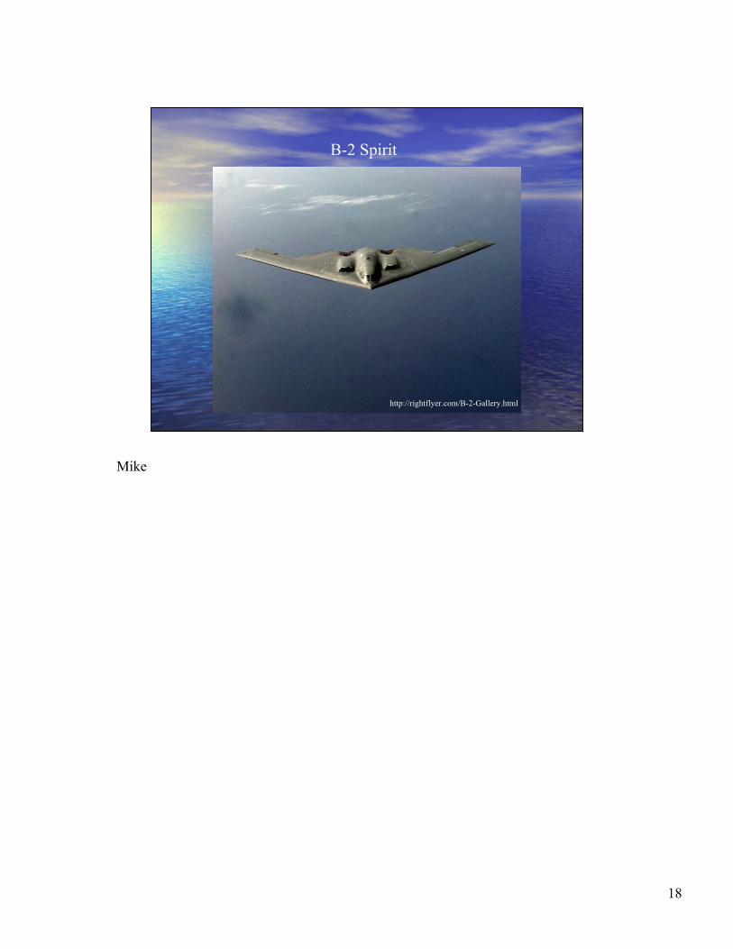
B-2 Spirit
http://rightflyer.com/B-2-Gallery.html
Mike

19
Specifications (1):
Primary function: Multi-role heavy bomber
Prime Contractor: Northrop Grumman Corp.
Contractor Team: Boeing Military Airplanes Co., General Electric Aircraft Engine Group and
Hughes Training Inc., Link Division
Power Plant: Four General Electric F-118-GE-100 engines
Thrust: 17,300 pounds each engine
Length: 69 feet (20.9 meters)
Height: 17 feet (5.1 meters)
Wingspan: 172 feet (52.12 meters)
Speed: High subsonic
Ceiling: 50,000 feet (15,152 meters)
Takeoff Weight (Typical): 336,500 pounds (152,635 kilograms)
Range: Intercontinental, unrefueled
Armament: Conventional or nuclear weapons
Payload: 40,000 pounds (18,144 kilograms)
Crew: Two pilotsDate Deployed: December 1993
Inventory: Active force: 21 (1 test); ANG: 0; Reserve: 0

20
Reasons for Existence:
- First designed to penetrate Soviet radar and deliver nuclear bombs to the Soviet Union
- After the fall of the USSR, it was converted for conventional warfare to carry JDAMs
- Also was to serve as a replacement for the B-52 bomber
Advantages:
- Low visual (at night) and radar visibility
- Able to fly 6,000 nm without refueling and 10,000 nm with one refuel
- Can hold up to 40,000 lb worth of munitions
- Can deliver munitions anywhere in the world in 24 hours
- Does not require fighter escorts due to low visibility and high survivability
Disadvantages:
- Stealth capability affected by bad weather
- Very costly, $2.2 Billion per plane
- High maintenance, requiring 25 man hours for preparation before each mission
- Requires special protective hangars and thus is hard to base anywhere but home
base at Whiteman Airforce Base, MO
21
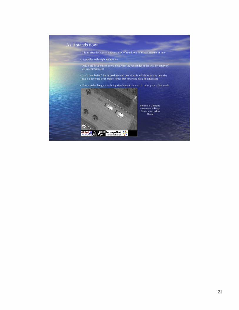
As it stands now:
- It is an effective way to delivery a lot of munitions in a short amount of time
- Is stealthy in the right conditions
- Only 5 are in operation at one time, with the remainder of the total inventory of
21 in refurbishment
- Is a “silver bullet” that is used in small quantities in which its unique qualities
give it a leverage over enemy forces that otherwise have an advantage
- New portable hangars are being developed to be used in other parts of the world
Portable B-2 hangarsconstructed at Diego
Garcia in the Indian
Ocean

22
http://www.af.mil/news/factsheets/B_2_Spirit.html

23
Boeing Blended-Wing-Body (BWB)Boeing Blended-Wing-Body (BWB)
-- Conventional Transports haveConventional Transports havebeen refined almost to their limitbeen refined almost to their limit
-- New direction to leap forward inNew direction to leap forward in
transport performancetransport performance
-- Goals:Goals:
-- Reduce Drag, and therebyReduce Drag, and thereby
lower fuel consumptionlower fuel consumption
-- Increase passengerIncrease passenger
complimentcompliment
-- Create a family of BWB a/cCreate a family of BWB a/c
http://www.boeing.com/phantom/bwb.html
24
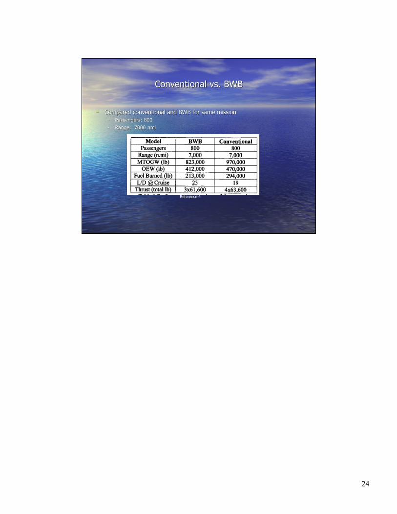
Conventional vs. BWBConventional vs. BWB
-- Compared conventional and BWB for same missionCompared conventional and BWB for same mission
-- Passengers: 800Passengers: 800
-- Range: 7000Range: 7000 nminmi
Reference 4

25
Unique Opportunities for BWBUnique Opportunities for BWB
-- Manufacturing part countManufacturing part count
-- 30% reduction in number of parts compared to conventional transports30% reduction in number of parts compared to conventional transports
-- Results fromResults from
-- elimination of 90elimination of 90°° joints with horizontal plains joints with horizontal plains
-- No track driven flaps, only simple hinged surfacesNo track driven flaps, only simple hinged surfaces
-- No SpoilersNo Spoilers
-- Also results in lower manufacturing costAlso results in lower manufacturing cost

26
Unique Opportunities for BWB (Cont.)Unique Opportunities for BWB (Cont.)
-- GrowthGrowth
-- Stretching aircraft laterally instead of longitudinallyStretching aircraft laterally instead of longitudinally
-- Results inResults in
-- Wing area and span increasing proportional to passenger increaseWing area and span increasing proportional to passenger increase
-- Planes ranging from 200-450 people in same familyPlanes ranging from 200-450 people in same family
Reference 4
27
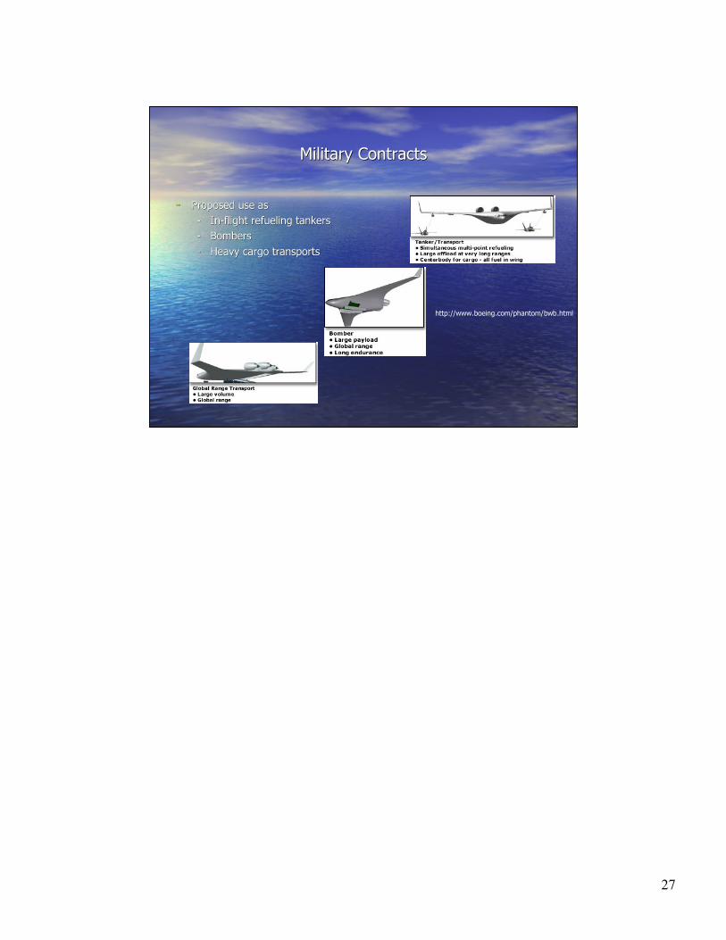
Military ContractsMilitary Contracts
-- Proposed use asProposed use as
-- In-flight refueling tankersIn-flight refueling tankers
-- BombersBombers
-- Heavy cargo transportsHeavy cargo transports
http://www.boeing.com/phantom/bwb.html

28
References1. J.K. Northrop, “The Development of the All-Wing Aircraft,” 35th Wilbur Wright Memorial Lecture, The
Royal Aeronautical Society Journal, Vol. 51, pp. 481-510, 1947.
2. Leo J. Kohn, The Flying Wings of Northrop, Aviation Publications, Milwaukee, 1974.
3. E.T. Wooldridge, Winged Wonders, The Story of the Flying Wings, Smithsonian Institute Press,
Washington, 1983.
4. Liebeck, R. “Design of Blended-Wing-Body Subsonic Transport”, AIAA 2002 A02-13493
5. Pilot Friend . Com, The Flying Wing, available at http://www.pilotfriend.com/century-of-
flight/Aviation%20history/jet%20age/flying%20wings.htm, March 13, 2003.
6. The Nerfugal Page, The Flying Wing, available at: http://www.nurflugel.com/Nurflugel/nurflugel.html,
March 12, 2003.
Aerostories.Com, Horten: Two Brothers, One wing, www.aerostories.com. March 10, 2003.
7. http://www.clw.org/milspend/b2_1999.html
8. http://www.iss.northropgrumman.com/products/usaf_products/b2/b2.html
9. http://www.af.mil/news/factsheets/B_2_Spirit.html
10. AIAA paper #A00-39894 - http://pdf.aiaa.org/downloads/2000/2000_4335.pdf
11. http://www.pilotfriend.com/century-of-flight/Aviation%20history/jet%20age/Northrop%20wing1.htm
12. http://www.stanford.edu/dept/news/report/news/july30/wing.html
13. http://zzyx.ucsc.edu/rcbees/aerodynamics/Flying%20Wings/part1.html
14. http://www.boeing.com/phantom/bwb.html
15. http://www.boeing.com/phantom/bwb.html