MATRIX DRIVE TECHNOLOGY - Control Global
11
MATRIX DRIVE TECHNOLOGY THE FUTURE IN ACTIVE FRONT END DRIVES This document details the Matrix Drive’s innovative low harmonic and regenerative technology and its advantages over conventional active front end (AFE) technology.
Transcript of MATRIX DRIVE TECHNOLOGY - Control Global
MATRIX DRIVE TECHNOLOGYT H E F U T U R E I N A C T I V E F R O N T E N D D R I V E S
This document details the Matrix Drive’s innovative low harmonic and regenerative technology and its advantages
over conventional active front end (AFE) technology.
V F D T E C H N O L O G Y
Conventional 6-pulse Drives are the cornerstone to electric motor control. Through 6-pulse drives we have been able to meet application needs while at the same time improving on process control, throughput, and energy savings. All these benefits come in a compact package with an economical cost, which typically results in a return on the investment in less than a year. Conventional 6-pulse drives achieve their benefits by converting AC input power to DC power. IGBTs are then used to create a pulse width modulated (PWM) waveform for variable speed motor control.
Conventional Active Front End (AFE) Drives implement two-way IGBT switching to provide variable speed motor control with the addition of low input harmonics and full regeneration. The input of the AFE interrupts normal current flow to force current into an input phase that would not normally have current. The result is an elevated DC bus and more continuous input current. An AFE also has the ability to take regenerative energy from the motor and direct it back on to the line to be distributed to other loads. A large input filter is implemented to ensure the IGBTs are isolated from the voltage supply. Newer versions of conventional AFE technology add additional IGBTs to the input section to create a three-level front end. This allows for lower than typical AFE input harmonics at the expense of additional efficiency losses.
Matrix Drive technology is different than conventional AFE drives. The difference lies within the matrix technology itself. Unlike conventional drives, Matrix Drives employ a system of nine bi-directional switches (IGBTs) arranged in a matrix to convert a three-phase AC input voltage directly into a three-phase AC output voltage. In essence, Matrix Drives take exactly what is needed from the powerline and passes it directly to the motor. Matrix technology eliminates the need for a rectifying circuit and DC smoothing circuit found in conventional AC six-pulse and AFE drives.
Matrix Drives incorporate a compact input filter to isolate the IGBTs from the voltage supply. This input filter circuit contains an AC film based capacitor. Six-pulse and AFE drives use electrolytic capacitors that have lifespans of 80,000 hours or more. AC film based capacitors have operational lifespans of 160,000 hours or more. Thus, the AC film capacitors will have a lifespan in excess of 10 years, with some studies showing double lifetimes or longer compared to electrolytic capacitors.
The key to the Matrix Drive’s power conversion is its constant use of input voltage to generate an output voltage. The constant use of input voltage is what leads to its natural low input current harmonic draw at any speed or load. Its bi-directional switches allow for seamless and automatic regeneration to the supply line for optimum energy savings. All of this leads to a highly efficient compact package for regenerative and/or low harmonic applications.
I N T R O D U C T I O N
A variable frequency drive is an electronic device that allows for the control of speed in an electric motor. Depending on the application, having this ability can provide a number of benefits including improvements in process control, efficiency, and power factor. Reductions in latent heating as well as extended machine life due to it’s inherent soft starting ability may also be gained. VFDs are used in a multitude of applications; from relatively simple applications like pumps and fans to more complicated applications like dynamometers.
The evolution of VFD technology stems from the need to boost motor control performance and to provide clean, efficient use of line power. To that end, recent advancements in VFD technology have made way for a drive using matrix technology. A Matrix Drive is an all-in-one solution for extremely low harmonics and/or full regeneration, and is the ultimate choice for power quality and energy savings. Additionally, a Matrix Drive delivers high performance in a compact, easy to install and use design to meet a wide variety of application requirements. In short, Matrix Drives are the next generation of active front end (AFE) drive technology.
While there have been other direct AC to AC converters, like cycloconverters (SCR based devices limited to line frequency), Yaskawa’s Matrix Drive is the first to use insulated-gate bipolar transistors (IGBTs). Using IGBTs required advanced process control never before used in a matrix converter topology. Yaskawa’s matrix IGBT design allows up to 400 hertz operation when supplied by a typical 50/60 Hz voltage supply for any variable torque or constant torque application.
Yaskawa’s present-day U1000 and Z1000U Matrix Drive series are not the first Matrix Drives manufactured
by Yaskawa. Yaskawa’s Matrix Drive design was initially developed for the elevator market to provide an all-in-one, compact regenerative drive solution. Recognizing that matrix technology could be used for much more, Yaskawa released its first commercially available Matrix Drive, the AC7 Matrix Converter. The AC7 was sold into select heavy industries, such as mining, oil & gas, elevators, and escalators. The first AC7 was sold and installed stateside in 2008. This has given Yaskawa over a decade of experience applying Matrix Drive technology to some of the most difficult applications in some of the most inhospitable environments. In April of 2015, Yaskawa launched its U1000 and Z1000U Matrix Drive lines to all markets. These new Matrix lines expanded the AC7’s capabilities by providing additional industry process control, higher power range, improved efficiency, and reduced size.
Thousands of Matrix Drives have been successfully installed since the U1000 and Z1000U launch. Matrix Drive technology has been used on every known application that can benefit from its compact, low harmonic and regenerative design.
Key Applications:
• Centrifuges
• Downhill Conveyors
• Escalators/Moving Walkways
• Extruders
• Fans
• Feeders
• Industrial Washers
• Lumber Industry
• Metal Working
• Mixers
• Pumps
• Pumpjacks
• Punch/Ram Presses
• Steel Grinders
• Test Dynamometers
• Winders
• Two generations of Matrix Drive control
• Over a decade of operational experience
• Thousands of successful installations
C E R T I F I E D T E S T R E S U L T S
This document shows the results of Yaskawa laboratory testing comparing a conventional AFE drive to a Matrix Drive. Both drives are rated for 20 HP at 480 V and each drive ran the same 20 HP, 24.1 A, 460 V, 1773 RPM, 60 Hz, 0.84 PF, and 93% efficient Marathon Electric Blue Max motor. During each test, the motor was run and loaded to various variable torque speed/load points including 100% torque at full speed. The calibrated, UL compliant test measurement equipment consisted of a Yokogawa WT1800 power analyzer, a Fluke 87V multimeter, and Yokogawa 701930 10 MHz current probes. The input line voltage was a balanced 480 V three phase supply. The motor load and speed was confirmed using a Himmelstein Model 723 torque transducer.
Additional test results use the same test measurement equipment to evaluate 60 HP, 480 V drives on a 60 HP, 69.5 A, 460 V, 1782 RPM, 60 Hz, 0.85 PF, and 95% efficient Marathon Electric XRI motor.
The key to the Matrix Drive’s power conversion is its constant use of input voltage to generate an output voltage. The constant use of input voltage is what leads to its natural low input current harmonic draw at any speed or load.
L1L2L3
x
x
x
IMT1
T3T2
L1L2L3
x
x
x
IMT1
T3T2
IMTSR IU
IV
IW
VU
U
V
W
VV
VW
IR
IS
IT
ER
ES
ET
S11S21
S31S12S22S32S13S23S33
Utility gridcf
=
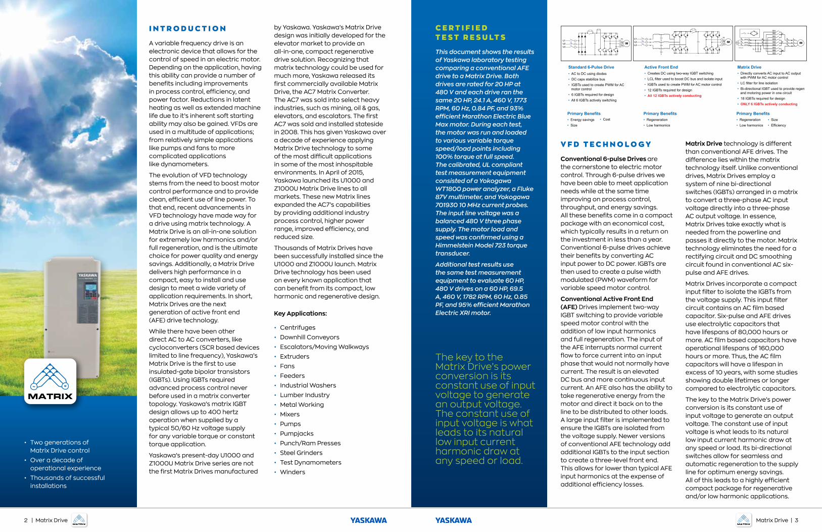
Standard 6-Pulse Drive• AC to DC using diodes• DC caps stabilize bus• IGBTs used to create PWM for AC motor control• 6 IGBTs required for design• All 6 IGBTs actively switching
Primary Benefits• Energy savings• Size
• Cost
Active Front End• Creates DC using two-way IGBT switching• LCL filter used to boost DC bus and isolate input• IGBTs used to create PWM for AC motor control• 12 IGBTs required for design• All 12 IGBTs actively conducting
Primary Benefits• Regeneration• Low harmonics
Matrix Drive• Directly converts AC input to AC output with PWM for AC motor control• LC filter for line isolation• Bi-directional IGBT used to provide regen and motoring power in one circuit• 18 IGBTs required for design• ONLY 6 IGBTs actively conducting
Primary Benefits• Regeneration• Low harmonics
• Size• Efficiency
Matrix Drive | 32 | Matrix Drive
Making a Selection Based on Harmonics
Conventional AFE and Matrix Drive technology both provide mitigation of input current harmonics at rated power and yet this is not where VFDs operate. VFDs are primarily used to boost power factor and overall system efficiency (energy savings), while also providing new and improved process control. VFDs accomplish energy savings by reducing speed to operate at the exact condition required to maintain demand. For example, a pump would be commanded to run slower to maintain demand and so that system pressure is not over charged. Both pump and fan drive systems will primarily operate between 50% and 80% of rated speed. Only during short periods of high demand, like a fan in fire mode, may a system run at or near rated speed. However, many systems are oversized to handle failure of a secondary system. So, under normal rated operating demand conditions these drive-motor systems may never operate near rated power.
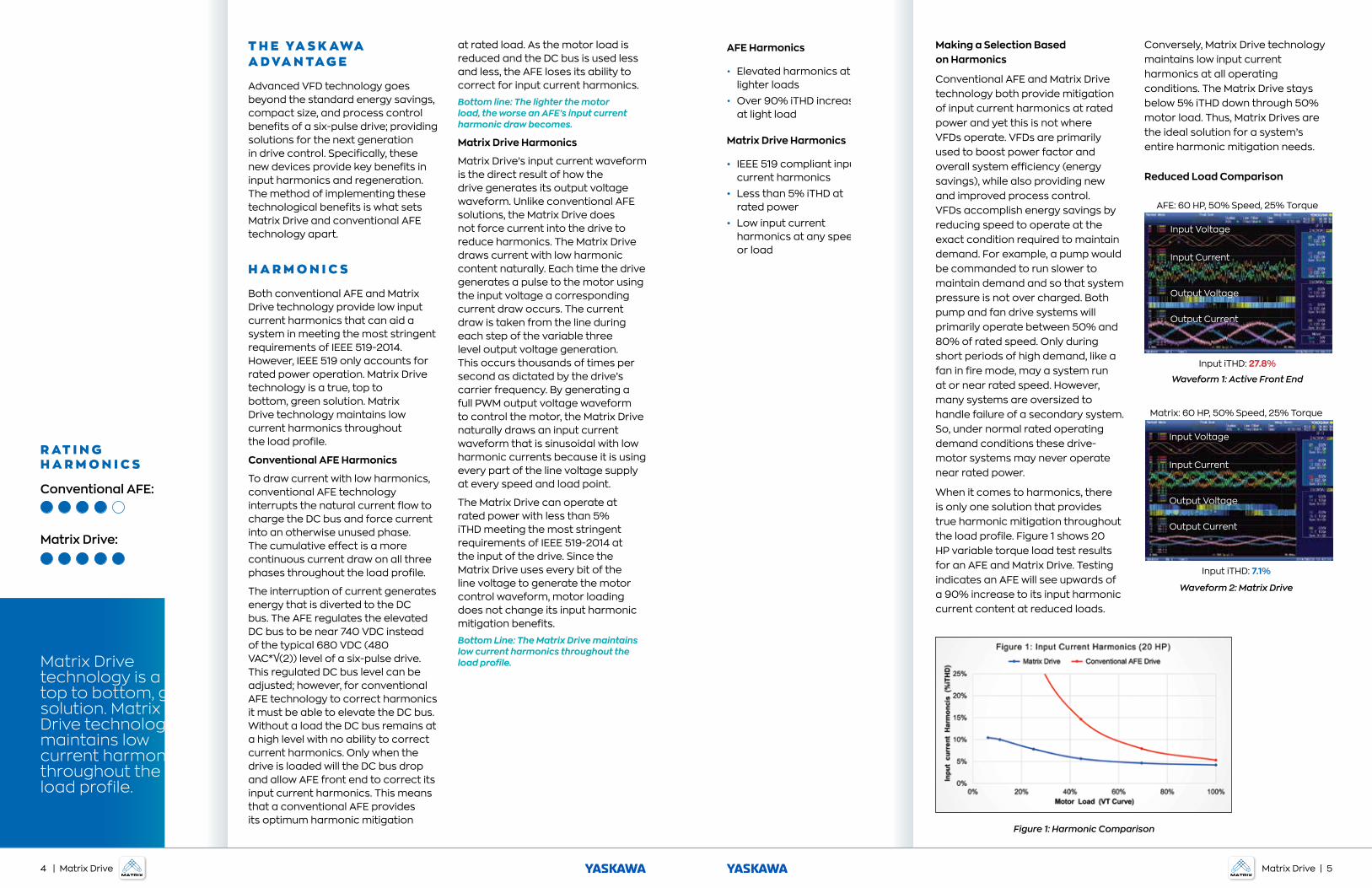
When it comes to harmonics, there is only one solution that provides true harmonic mitigation throughout the load profile. Figure 1 shows 20 HP variable torque load test results for an AFE and Matrix Drive. Testing indicates an AFE will see upwards of a 90% increase to its input harmonic current content at reduced loads.
Conversely, Matrix Drive technology maintains low input current harmonics at all operating conditions. The Matrix Drive stays below 5% iTHD down through 50% motor load. Thus, Matrix Drives are the ideal solution for a system’s entire harmonic mitigation needs.
Reduced Load Comparison
T H E YA S K AWA A D VA N TA G E
Advanced VFD technology goes beyond the standard energy savings, compact size, and process control benefits of a six-pulse drive; providing solutions for the next generation in drive control. Specifically, these new devices provide key benefits in input harmonics and regeneration. The method of implementing these technological benefits is what sets Matrix Drive and conventional AFE technology apart.
H A R M O N I C S
Both conventional AFE and Matrix Drive technology provide low input current harmonics that can aid a system in meeting the most stringent requirements of IEEE 519-2014. However, IEEE 519 only accounts for rated power operation. Matrix Drive technology is a true, top to bottom, green solution. Matrix Drive technology maintains low current harmonics throughout the load profile.
Conventional AFE Harmonics
To draw current with low harmonics, conventional AFE technology interrupts the natural current flow to charge the DC bus and force current into an otherwise unused phase. The cumulative effect is a more continuous current draw on all three phases throughout the load profile.
The interruption of current generates energy that is diverted to the DC bus. The AFE regulates the elevated DC bus to be near 740 VDC instead of the typical 680 VDC (480 VAC*√(2)) level of a six-pulse drive. This regulated DC bus level can be adjusted; however, for conventional AFE technology to correct harmonics it must be able to elevate the DC bus. Without a load the DC bus remains at a high level with no ability to correct current harmonics. Only when the drive is loaded will the DC bus drop and allow AFE front end to correct its input current harmonics. This means that a conventional AFE provides its optimum harmonic mitigation
at rated load. As the motor load is reduced and the DC bus is used less and less, the AFE loses its ability to correct for input current harmonics.
Bottom line: The lighter the motor load, the worse an AFE’s input current harmonic draw becomes.
Matrix Drive Harmonics
Matrix Drive’s input current waveform is the direct result of how the drive generates its output voltage waveform. Unlike conventional AFE solutions, the Matrix Drive does not force current into the drive to reduce harmonics. The Matrix Drive draws current with low harmonic content naturally. Each time the drive generates a pulse to the motor using the input voltage a corresponding current draw occurs. The current draw is taken from the line during each step of the variable three level output voltage generation. This occurs thousands of times per second as dictated by the drive’s carrier frequency. By generating a full PWM output voltage waveform to control the motor, the Matrix Drive naturally draws an input current waveform that is sinusoidal with low harmonic currents because it is using every part of the line voltage supply at every speed and load point.
The Matrix Drive can operate at rated power with less than 5% iTHD meeting the most stringent requirements of IEEE 519-2014 at the input of the drive. Since the Matrix Drive uses every bit of the line voltage to generate the motor control waveform, motor loading does not change its input harmonic mitigation benefits.
Bottom Line: The Matrix Drive maintains low current harmonics throughout the load profile.
R AT I N G H A R M O N I C S
Conventional AFE:
Matrix Drive:
AFE Harmonics
• Elevated harmonics at lighter loads
• Over 90% iTHD increase at light load
Matrix Drive Harmonics
• IEEE 519 compliant input current harmonics
• Less than 5% iTHD at rated power
• Low input current harmonics at any speed or load
Input Voltage
Input Current
Output Voltage
Output Current
AFE: 60 HP, 50% Speed, 25% Torque
Input iTHD: 27.8%
Waveform 1: Active Front End
Input Voltage
Input Current
Output Voltage
Output Current
Matrix: 60 HP, 50% Speed, 25% Torque
Input iTHD: 7.1%
Waveform 2: Matrix Drive
Figure 1: Harmonic Comparison
Matrix Drive technology is a true, top to bottom, green solution. Matrix Drive technology maintains low current harmonics throughout the load profile.
4 | Matrix Drive Matrix Drive | 5
Waveforms 1 & 2 show the variable torque loading results of a 60 HP motor operated by a conventional AFE and a Matrix Drive at 50% speed, 25% torque. Waveform 1 shows that the AFE’s input current spikes—making up the fundamental current waveform—have high peaks and are spread out. The resulting input current waveform has 28% iTHD (input current harmonics). Conversely, the Matrix Drive maintains its low current harmonic performance throughout the speed range. At 50% speed, 25% torque, the Matrix Drive’s input current harmonics are only 7% iTHD.
Harmonic Mitigation Benefits Unique to Matrix Drives
The Matrix Drive has the ability to go one step further in its harmonic attenuation using a built-in across-the-line function (Eco-Mode). The Matrix Drive can seamlessly and automatically provide line voltage directly to the motor.
Whenever an application’s frequency requirement matches the grid frequency, the Matrix Drive can synchronize the motor to grid voltage. This built-in, across-the-line function eliminates input current harmonics. Since the switches (IGBTs) are now static, switching losses and electrical motor noise is eliminated. This means higher drive and motor efficiency.
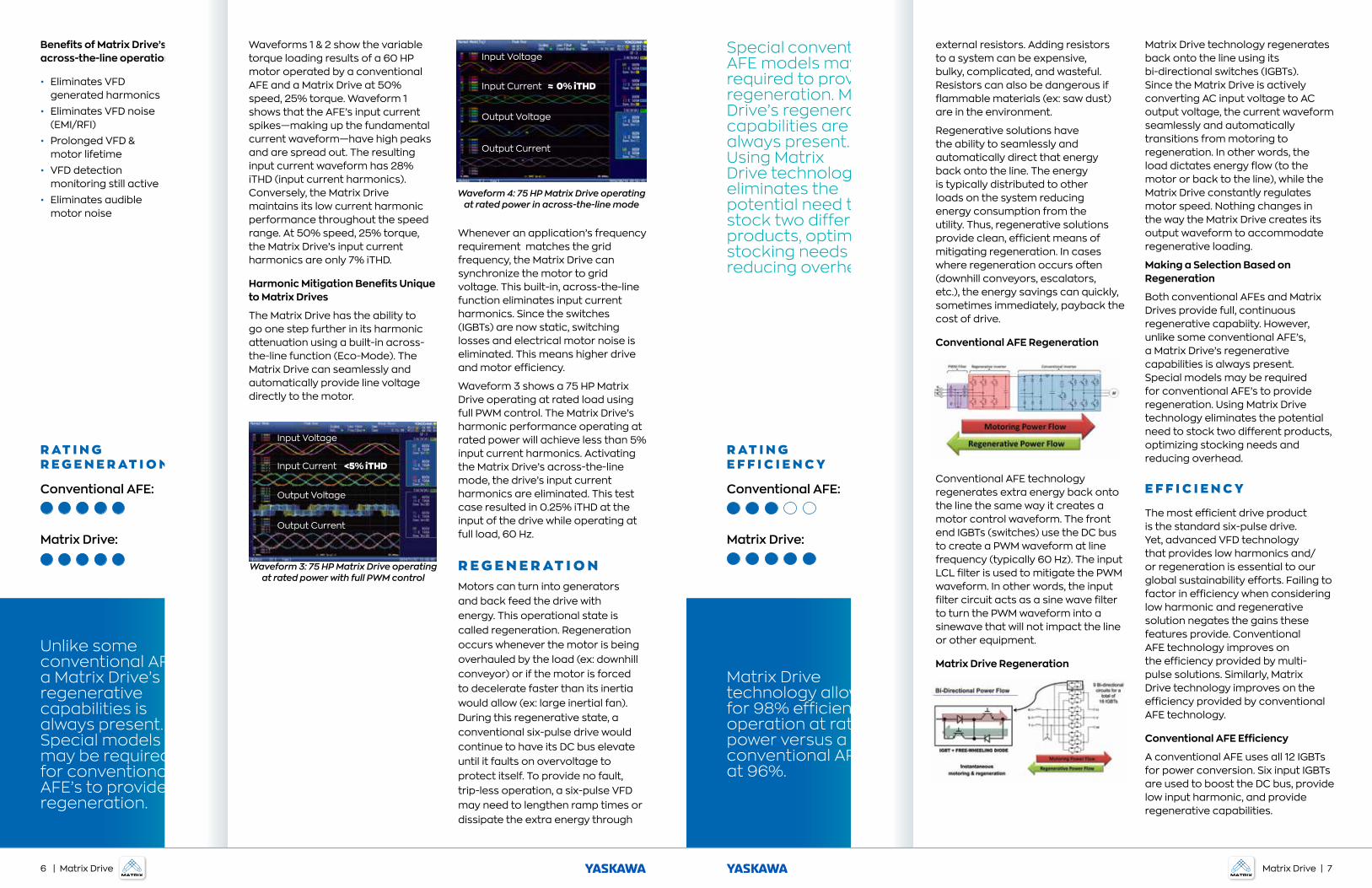
Waveform 3 shows a 75 HP Matrix Drive operating at rated load using full PWM control. The Matrix Drive’s harmonic performance operating at rated power will achieve less than 5% input current harmonics. Activating the Matrix Drive’s across-the-line mode, the drive’s input current harmonics are eliminated. This test case resulted in 0.25% iTHD at the input of the drive while operating at full load, 60 Hz.
R E G E N E R AT I O NMotors can turn into generators and back feed the drive with energy. This operational state is called regeneration. Regeneration occurs whenever the motor is being overhauled by the load (ex: downhill conveyor) or if the motor is forced to decelerate faster than its inertia would allow (ex: large inertial fan). During this regenerative state, a conventional six-pulse drive would continue to have its DC bus elevate until it faults on overvoltage to protect itself. To provide no fault, trip-less operation, a six-pulse VFD may need to lengthen ramp times or dissipate the extra energy through
Benefits of Matrix Drive’s across-the-line operation
• Eliminates VFD generated harmonics
• Eliminates VFD noise (EMI/RFI)
• Prolonged VFD & motor lifetime
• VFD detection monitoring still active
• Eliminates audible motor noise
Input Voltage
Input Current <5% iTHD
Output Voltage
Output Current
Waveform 3: 75 HP Matrix Drive operating at rated power with full PWM control
Waveform 4: 75 HP Matrix Drive operating at rated power in across-the-line mode
R AT I N G R E G E N E R AT I O N
Conventional AFE:
Matrix Drive:
external resistors. Adding resistors to a system can be expensive, bulky, complicated, and wasteful. Resistors can also be dangerous if flammable materials (ex: saw dust) are in the environment.
Regenerative solutions have the ability to seamlessly and automatically direct that energy back onto the line. The energy is typically distributed to other loads on the system reducing energy consumption from the utility. Thus, regenerative solutions provide clean, efficient means of mitigating regeneration. In cases where regeneration occurs often (downhill conveyors, escalators, etc.), the energy savings can quickly, sometimes immediately, payback the cost of drive.
Conventional AFE Regeneration
Conventional AFE technology regenerates extra energy back onto the line the same way it creates a motor control waveform. The front end IGBTs (switches) use the DC bus to create a PWM waveform at line frequency (typically 60 Hz). The input LCL filter is used to mitigate the PWM waveform. In other words, the input filter circuit acts as a sine wave filter to turn the PWM waveform into a sinewave that will not impact the line or other equipment.
Matrix Drive Regeneration
Matrix Drive technology regenerates back onto the line using its bi-directional switches (IGBTs). Since the Matrix Drive is actively converting AC input voltage to AC output voltage, the current waveform seamlessly and automatically transitions from motoring to regeneration. In other words, the load dictates energy flow (to the motor or back to the line), while the Matrix Drive constantly regulates motor speed. Nothing changes in the way the Matrix Drive creates its output waveform to accommodate regenerative loading.
Making a Selection Based on Regeneration
Both conventional AFEs and Matrix Drives provide full, continuous regenerative capabiity. However, unlike some conventional AFE’s, a Matrix Drive’s regenerative capabilities is always present. Special models may be required for conventional AFE’s to provide regeneration. Using Matrix Drive technology eliminates the potential need to stock two different products, optimizing stocking needs and reducing overhead.
E F F I C I E N C Y
The most efficient drive product is the standard six-pulse drive. Yet, advanced VFD technology that provides low harmonics and/or regeneration is essential to our global sustainability efforts. Failing to factor in efficiency when considering low harmonic and regenerative solution negates the gains these features provide. Conventional AFE technology improves on the efficiency provided by multi-pulse solutions. Similarly, Matrix Drive technology improves on the efficiency provided by conventional AFE technology.
Conventional AFE Efficiency
A conventional AFE uses all 12 IGBTs for power conversion. Six input IGBTs are used to boost the DC bus, provide low input harmonic, and provide regenerative capabilities.
R AT I N G E F F I C I E N C Y
Conventional AFE:
Matrix Drive:
Special conventional AFE models may be required to provide regeneration. Matrix Drive’s regenerative capabilities are always present. Using Matrix Drive technology eliminates the potential need to stock two different products, optimizing stocking needs and reducing overhead.
Matrix Drive technology allows for 98% efficient operation at rated power versus a conventional AFE at 96%.
Unlike some conventional AFE’s, a Matrix Drive’s regenerative capabilities is always present. Special models may be required for conventional AFE’s to provide regeneration.
Input Voltage
Input Current ≈ 0% iTHD
Output Voltage
Output Current
6 | Matrix Drive Matrix Drive | 7
Matrix Drives maintain highest efficiency and lowest harmonics throughout the operating range.
Increases in efficiency mean lower facility cooling requirements, less panel fans, and longer drive lifetime (MTBF).
The six output IGBTs are used to generate the motor’s PWM voltage waveform. Therefore, all 12 IGBTs are required for active power conversion. The result is approximately 96% efficient operation at rated power. At reduced loads, a conventional AFE’s harmonic mitigation efforts are reduced. Higher harmonics leads to lower power factor. The combination of higher harmonics, lower power factor, and 12 IGBT’s worth of switching losses lead to lower operational efficiency at reduced load.
Matrix Drive Efficiency
Matrix Drive technology is comprised of nine bi-direction switches, or 18 IGBTs, and a compact input filter circuit. The impedance of the filter circuit is low to maximize efficiency but sufficient enough to provide isolation from the line.
Matrix Drive power conversion is accomplished using its nine bi-direction switches. Each bi-directional switch has two IGBT for a total of eighteen IGBTs. Although all eighteen IGBT are used for power conversion only six IGBTs are actively conducting at any point in time. This is equivalent to the output power section of a conventional AFE or a standard 6-pulse drive. There are no additional switches needed to condition the line. The Matrix Drive’s low input harmonic current draw is naturally generated as it creates its output PWM waveform.
Regeneration is seamless and automatic as the motor load changes.
Matrix Drives are clean power solutions. Every bit of the input voltage is used to generate the output waveform. The result is continuous current draw throughout the load profile. More continuous current means less harmonic content, which in turn leads to higher power factor. The combination of lower IGBT switching losses, lower harmonics, smaller isolation filter components, and higher power factor allows the Matrix Drive the most efficient low harmonic and regenerative technology on the market. At rated power, Matrix Drives operate at approximately 98% efficiency. The Matrix Drive’s efficiency stays high throughout the load range.
Making a Selection Based on Efficiency
Matrix Drives have more switches in their design than conventional AFEs, but less active switching. The losses are in the switching and not the number of switches. To elaborate, AFEs use two independent inverters: one to drive the motor, one to drive the line. Two inverters means twice the switching losses. Matrix Drives have only one active inverter.
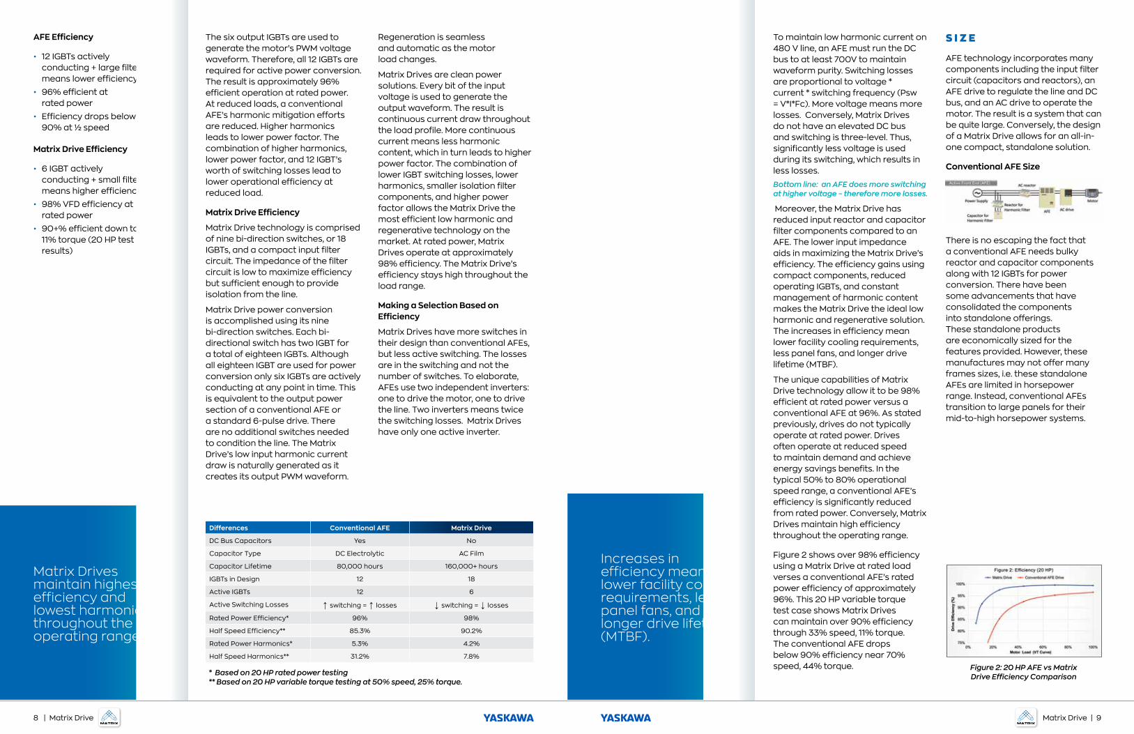
Differences Conventional AFE Matrix Drive
DC Bus Capacitors Yes No
Capacitor Type DC Electrolytic AC Film
Capacitor Lifetime 80,000 hours 160,000+ hours
IGBTs in Design 12 18
Active IGBTs 12 6
Active Switching Losses ↑ switching = ↑ losses ↓ switching = ↓ losses
Rated Power Efficiency* 96% 98%
Half Speed Efficiency** 85.3% 90.2%
Rated Power Harmonics* 5.3% 4.2%
Half Speed Harmonics** 31.2% 7.8%
* Based on 20 HP rated power testing** Based on 20 HP variable torque testing at 50% speed, 25% torque.
To maintain low harmonic current on 480 V line, an AFE must run the DC bus to at least 700V to maintain waveform purity. Switching losses are proportional to voltage * current * switching frequency (Psw = V*I*Fc). More voltage means more losses. Conversely, Matrix Drives do not have an elevated DC bus and switching is three-level. Thus, significantly less voltage is used during its switching, which results in less losses.
Bottom line: an AFE does more switching at higher voltage – therefore more losses.
Moreover, the Matrix Drive has reduced input reactor and capacitor filter components compared to an AFE. The lower input impedance aids in maximizing the Matrix Drive’s efficiency. The efficiency gains using compact components, reduced operating IGBTs, and constant management of harmonic content makes the Matrix Drive the ideal low harmonic and regenerative solution. The increases in efficiency mean lower facility cooling requirements, less panel fans, and longer drive lifetime (MTBF).
The unique capabilities of Matrix Drive technology allow it to be 98% efficient at rated power versus a conventional AFE at 96%. As stated previously, drives do not typically operate at rated power. Drives often operate at reduced speed to maintain demand and achieve energy savings benefits. In the typical 50% to 80% operational speed range, a conventional AFE’s efficiency is significantly reduced from rated power. Conversely, Matrix Drives maintain high efficiency throughout the operating range.
Figure 2 shows over 98% efficiency using a Matrix Drive at rated load verses a conventional AFE’s rated power efficiency of approximately 96%. This 20 HP variable torque test case shows Matrix Drives can maintain over 90% efficiency through 33% speed, 11% torque. The conventional AFE drops below 90% efficiency near 70% speed, 44% torque.
S I Z E
AFE technology incorporates many components including the input filter circuit (capacitors and reactors), an AFE drive to regulate the line and DC bus, and an AC drive to operate the motor. The result is a system that can be quite large. Conversely, the design of a Matrix Drive allows for an all-in-one compact, standalone solution.
Conventional AFE Size
There is no escaping the fact that a conventional AFE needs bulky reactor and capacitor components along with 12 IGBTs for power conversion. There have been some advancements that have consolidated the components into standalone offerings. These standalone products are economically sized for the features provided. However, these manufactures may not offer many frames sizes, i.e. these standalone AFEs are limited in horsepower range. Instead, conventional AFEs transition to large panels for their mid-to-high horsepower systems.
Figure 2: 20 HP AFE vs Matrix Drive Efficiency Comparison
AFE Efficiency
• 12 IGBTs actively conducting + large filter means lower efficiency
• 96% efficient at rated power
• Efficiency drops below 90% at ½ speed
Matrix Drive Efficiency
• 6 IGBT actively conducting + small filter means higher efficiency
• 98% VFD efficiency at rated power
• 90+% efficient down to 11% torque (20 HP test results)
8 | Matrix Drive Matrix Drive | 9
Matrix Drives are unique in the fact that they offer regenerative and low harmonic capabilities in a standalone offering through 350 HP.
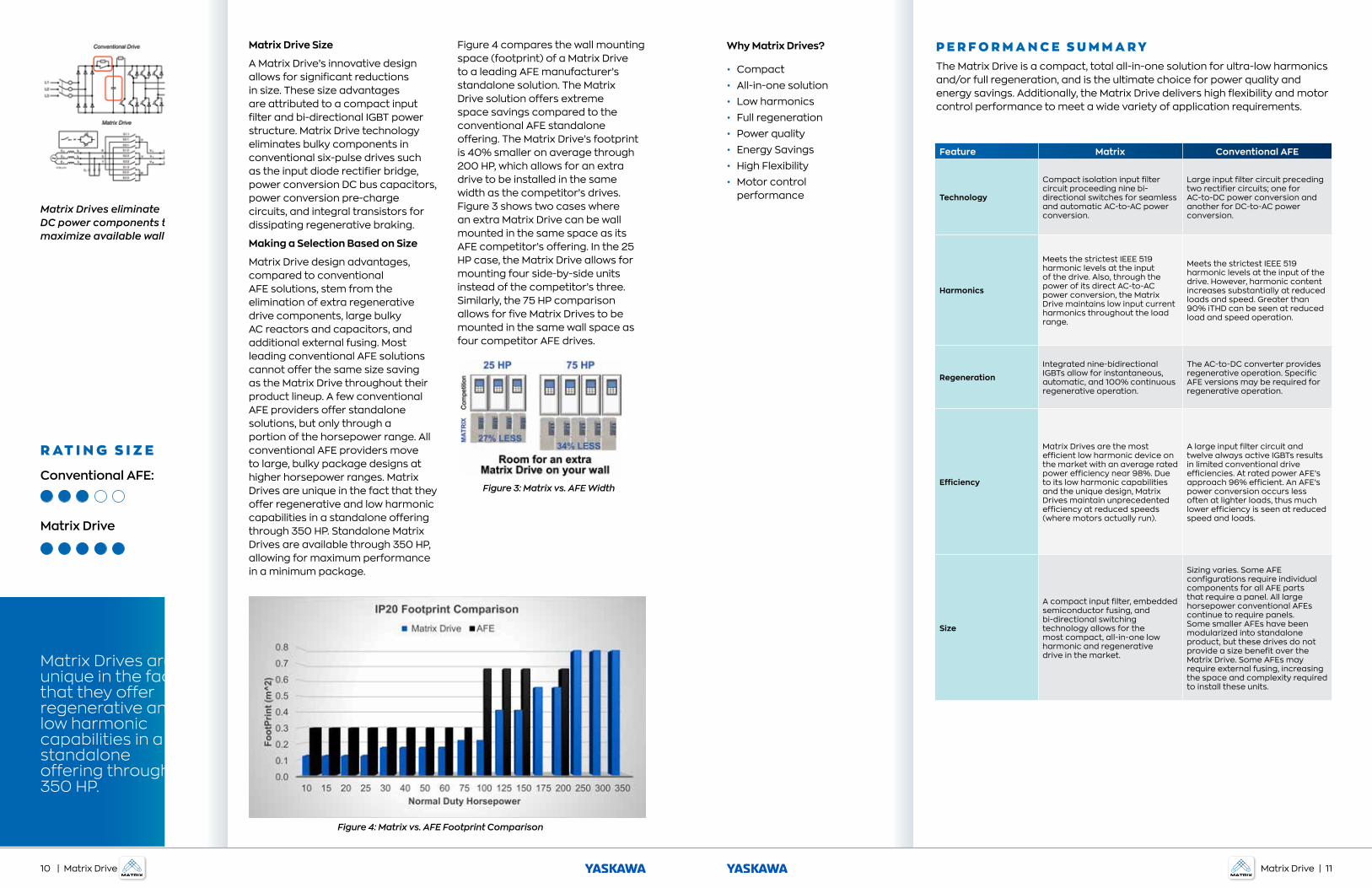
Matrix Drive Size
A Matrix Drive’s innovative design allows for significant reductions in size. These size advantages are attributed to a compact input filter and bi-directional IGBT power structure. Matrix Drive technology eliminates bulky components in conventional six-pulse drives such as the input diode rectifier bridge, power conversion DC bus capacitors, power conversion pre-charge circuits, and integral transistors for dissipating regenerative braking.
Making a Selection Based on Size
Matrix Drive design advantages, compared to conventional AFE solutions, stem from the elimination of extra regenerative drive components, large bulky AC reactors and capacitors, and additional external fusing. Most leading conventional AFE solutions cannot offer the same size saving as the Matrix Drive throughout their product lineup. A few conventional AFE providers offer standalone solutions, but only through a portion of the horsepower range. All conventional AFE providers move to large, bulky package designs at higher horsepower ranges. Matrix Drives are unique in the fact that they offer regenerative and low harmonic capabilities in a standalone offering through 350 HP. Standalone Matrix Drives are available through 350 HP, allowing for maximum performance in a minimum package.
Figure 4 compares the wall mounting space (footprint) of a Matrix Drive to a leading AFE manufacturer’s standalone solution. The Matrix Drive solution offers extreme space savings compared to the conventional AFE standalone offering. The Matrix Drive’s footprint is 40% smaller on average through 200 HP, which allows for an extra drive to be installed in the same width as the competitor’s drives. Figure 3 shows two cases where an extra Matrix Drive can be wall mounted in the same space as its AFE competitor’s offering. In the 25 HP case, the Matrix Drive allows for mounting four side-by-side units instead of the competitor’s three. Similarly, the 75 HP comparison allows for five Matrix Drives to be mounted in the same wall space as four competitor AFE drives.
Matrix Drives eliminate DC power components to maximize available wall space.
R AT I N G S I Z E
Conventional AFE:
Matrix Drive
Figure 4: Matrix vs. AFE Footprint Comparison
Figure 3: Matrix vs. AFE Width
P E R F O R M A N C E S U M M A R YThe Matrix Drive is a compact, total all-in-one solution for ultra-low harmonics and/or full regeneration, and is the ultimate choice for power quality and energy savings. Additionally, the Matrix Drive delivers high flexibility and motor control performance to meet a wide variety of application requirements.
Feature Matrix Conventional AFE
Technology
Compact isolation input filter circuit proceeding nine bi-directional switches for seamless and automatic AC-to-AC power conversion.
Large input filter circuit preceding two rectifier circuits; one for AC-to-DC power conversion and another for DC-to-AC power conversion.
Harmonics
Meets the strictest IEEE 519 harmonic levels at the input of the drive. Also, through the power of its direct AC-to-AC power conversion, the Matrix Drive maintains low input current harmonics throughout the load range.
Meets the strictest IEEE 519 harmonic levels at the input of the drive. However, harmonic content increases substantially at reduced loads and speed. Greater than 90% iTHD can be seen at reduced load and speed operation.
Regeneration
Integrated nine-bidirectional IGBTs allow for instantaneous, automatic, and 100% continuous regenerative operation.
The AC-to-DC converter provides regenerative operation. Specific AFE versions may be required for regenerative operation.
Efficiency
Matrix Drives are the most efficient low harmonic device on the market with an average rated power efficiency near 98%. Due to its low harmonic capabilities and the unique design, Matrix Drives maintain unprecedented efficiency at reduced speeds (where motors actually run).
A large input filter circuit and twelve always active IGBTs results in limited conventional drive efficiencies. At rated power AFE’s approach 96% efficient. An AFE’s power conversion occurs less often at lighter loads, thus much lower efficiency is seen at reduced speed and loads.
Size
A compact input filter, embedded semiconductor fusing, and bi-directional switching technology allows for the most compact, all-in-one low harmonic and regenerative drive in the market.
Sizing varies. Some AFE configurations require individual components for all AFE parts that require a panel. All large horsepower conventional AFEs continue to require panels. Some smaller AFEs have been modularized into standalone product, but these drives do not provide a size benefit over the Matrix Drive. Some AFEs may require external fusing, increasing the space and complexity required to install these units.
Why Matrix Drives?
• Compact
• All-in-one solution
• Low harmonics
• Full regeneration
• Power quality
• Energy Savings
• High Flexibility
• Motor control performance
10 | Matrix Drive Matrix Drive | 11
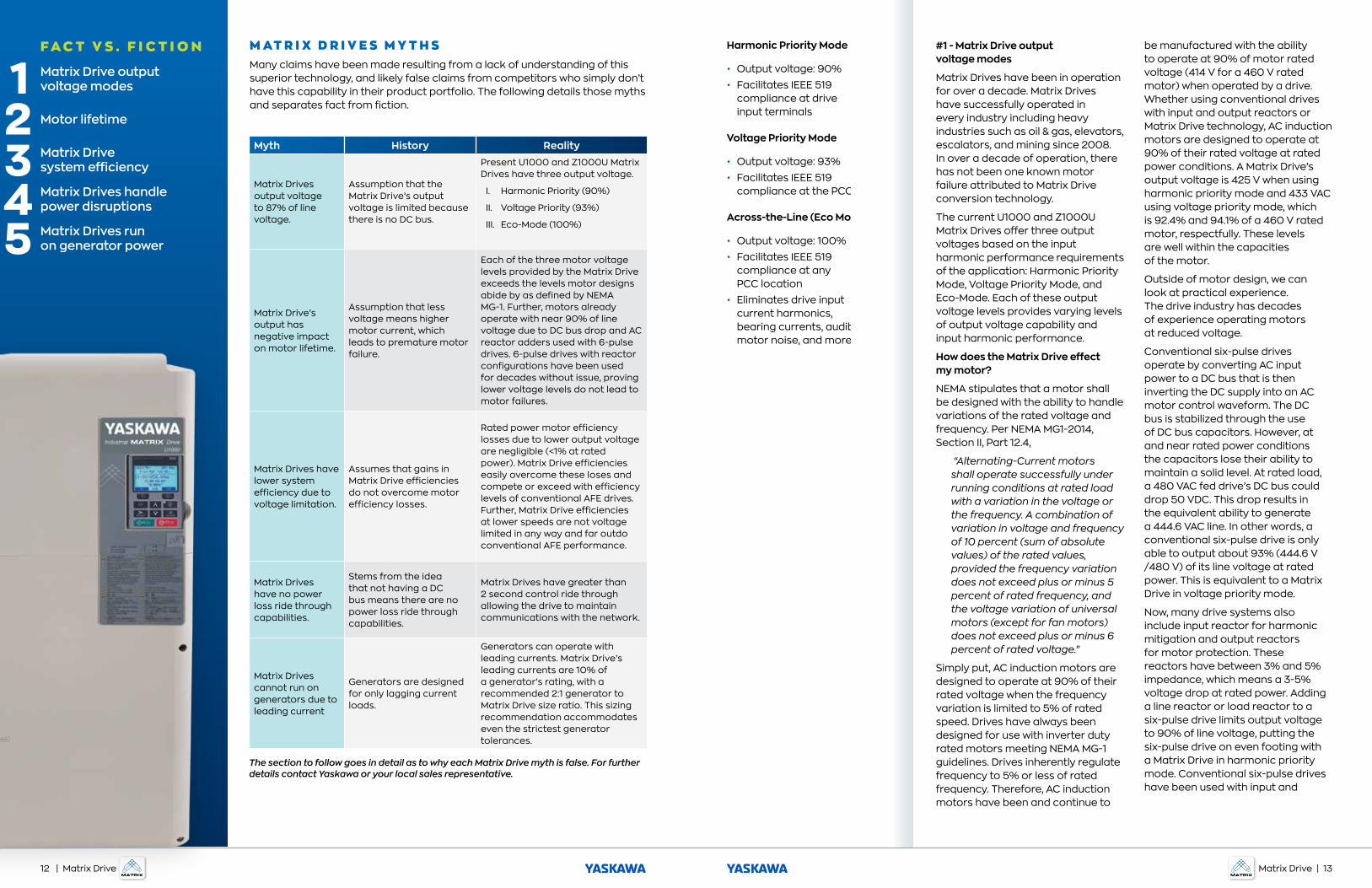
M AT R I X D R I V E S M Y T H SMany claims have been made resulting from a lack of understanding of this superior technology, and likely false claims from competitors who simply don’t have this capability in their product portfolio. The following details those myths and separates fact from fiction.
Myth History Reality
Matrix Drives output voltage to 87% of line voltage.
Assumption that the Matrix Drive’s output voltage is limited because there is no DC bus.
Present U1000 and Z1000U Matrix Drives have three output voltage.
I. Harmonic Priority (90%)
II. Voltage Priority (93%)
III. Eco-Mode (100%)
Matrix Drive’s output has negative impact on motor lifetime.
Assumption that less voltage means higher motor current, which leads to premature motor failure.
Each of the three motor voltage levels provided by the Matrix Drive exceeds the levels motor designs abide by as defined by NEMA MG-1. Further, motors already operate with near 90% of line voltage due to DC bus drop and AC reactor adders used with 6-pulse drives. 6-pulse drives with reactor configurations have been used for decades without issue, proving lower voltage levels do not lead to motor failures.
Matrix Drives have lower system efficiency due to voltage limitation.
Assumes that gains in Matrix Drive efficiencies do not overcome motor efficiency losses.
Rated power motor efficiency losses due to lower output voltage are negligible (<1% at rated power). Matrix Drive efficiencies easily overcome these loses and compete or exceed with efficiency levels of conventional AFE drives. Further, Matrix Drive efficiencies at lower speeds are not voltage limited in any way and far outdo conventional AFE performance.
Matrix Drives have no power loss ride through capabilities.
Stems from the idea that not having a DC bus means there are no power loss ride through capabilities.
Matrix Drives have greater than 2 second control ride through allowing the drive to maintain communications with the network.
Matrix Drives cannot run on generators due to leading current
Generators are designed for only lagging current loads.
Generators can operate with leading currents. Matrix Drive’s leading currents are 10% of a generator’s rating, with a recommended 2:1 generator to Matrix Drive size ratio. This sizing recommendation accommodates even the strictest generator tolerances.
The section to follow goes in detail as to why each Matrix Drive myth is false. For further details contact Yaskawa or your local sales representative.
#1 - Matrix Drive output voltage modes
Matrix Drives have been in operation for over a decade. Matrix Drives have successfully operated in every industry including heavy industries such as oil & gas, elevators, escalators, and mining since 2008. In over a decade of operation, there has not been one known motor failure attributed to Matrix Drive conversion technology.
The current U1000 and Z1000U Matrix Drives offer three output voltages based on the input harmonic performance requirements of the application: Harmonic Priority Mode, Voltage Priority Mode, and Eco-Mode. Each of these output voltage levels provides varying levels of output voltage capability and input harmonic performance.
How does the Matrix Drive effect my motor?
NEMA stipulates that a motor shall be designed with the ability to handle variations of the rated voltage and frequency. Per NEMA MG1-2014, Section II, Part 12.4,
“Alternating-Current motors shall operate successfully under running conditions at rated load with a variation in the voltage or the frequency. A combination of variation in voltage and frequency of 10 percent (sum of absolute values) of the rated values, provided the frequency variation does not exceed plus or minus 5 percent of rated frequency, and the voltage variation of universal motors (except for fan motors) does not exceed plus or minus 6 percent of rated voltage.”
Simply put, AC induction motors are designed to operate at 90% of their rated voltage when the frequency variation is limited to 5% of rated speed. Drives have always been designed for use with inverter duty rated motors meeting NEMA MG-1 guidelines. Drives inherently regulate frequency to 5% or less of rated frequency. Therefore, AC induction motors have been and continue to
be manufactured with the ability to operate at 90% of motor rated voltage (414 V for a 460 V rated motor) when operated by a drive. Whether using conventional drives with input and output reactors or Matrix Drive technology, AC induction motors are designed to operate at 90% of their rated voltage at rated power conditions. A Matrix Drive’s output voltage is 425 V when using harmonic priority mode and 433 VAC using voltage priority mode, which is 92.4% and 94.1% of a 460 V rated motor, respectfully. These levels are well within the capacities of the motor.
Outside of motor design, we can look at practical experience. The drive industry has decades of experience operating motors at reduced voltage.
Conventional six-pulse drives operate by converting AC input power to a DC bus that is then inverting the DC supply into an AC motor control waveform. The DC bus is stabilized through the use of DC bus capacitors. However, at and near rated power conditions the capacitors lose their ability to maintain a solid level. At rated load, a 480 VAC fed drive’s DC bus could drop 50 VDC. This drop results in the equivalent ability to generate a 444.6 VAC line. In other words, a conventional six-pulse drive is only able to output about 93% (444.6 V /480 V) of its line voltage at rated power. This is equivalent to a Matrix Drive in voltage priority mode.
Now, many drive systems also include input reactor for harmonic mitigation and output reactors for motor protection. These reactors have between 3% and 5% impedance, which means a 3-5% voltage drop at rated power. Adding a line reactor or load reactor to a six-pulse drive limits output voltage to 90% of line voltage, putting the six-pulse drive on even footing with a Matrix Drive in harmonic priority mode. Conventional six-pulse drives have been used with input and
Harmonic Priority Mode
• Output voltage: 90%
• Facilitates IEEE 519 compliance at drive input terminals
Voltage Priority Mode
• Output voltage: 93%
• Facilitates IEEE 519 compliance at the PCC
Across-the-Line (Eco Mode)
• Output voltage: 100%
• Facilitates IEEE 519 compliance at any PCC location
• Eliminates drive input current harmonics, bearing currents, audible motor noise, and more
F A C T V S . F I C T I O N
Matrix Drive output voltage modes
Motor lifetime
Matrix Drive system efficiency
Matrix Drives handle power disruptions
Matrix Drives run on generator power
12 | Matrix Drive Matrix Drive | 13
output reactors for decades without any adverse motor effects due to their supplied voltage. Therefore, motors have already proven to show a propensity for successful, long operational lives at all Matrix Drive output voltage levels.
#2 - Motor lifetime
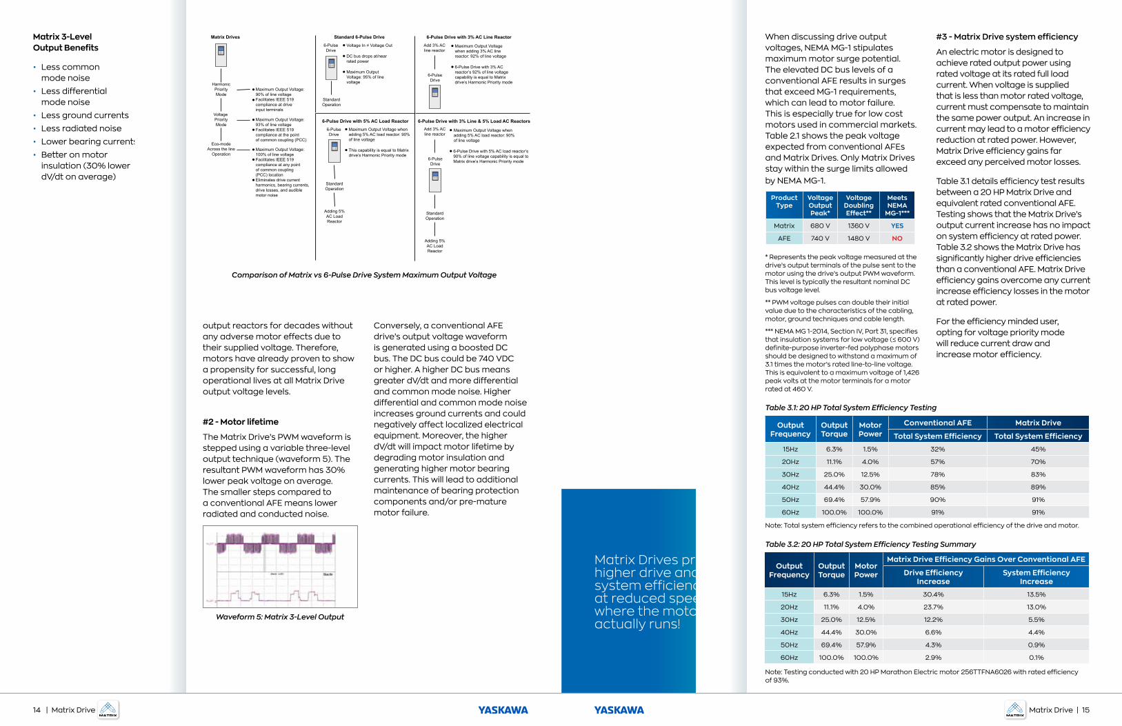
The Matrix Drive’s PWM waveform is stepped using a variable three-level output technique (waveform 5). The resultant PWM waveform has 30% lower peak voltage on average. The smaller steps compared to a conventional AFE means lower radiated and conducted noise.
Conversely, a conventional AFE drive’s output voltage waveform is generated using a boosted DC bus. The DC bus could be 740 VDC or higher. A higher DC bus means greater dV/dt and more differential and common mode noise. Higher differential and common mode noise increases ground currents and could negatively affect localized electrical equipment. Moreover, the higher dV/dt will impact motor lifetime by degrading motor insulation and generating higher motor bearing currents. This will lead to additional maintenance of bearing protection components and/or pre-mature motor failure.
Waveform 5: Matrix 3-Level Output
Matrix 3-Level Output Benefits
• Less common mode noise
• Less differential mode noise
• Less ground currents
• Less radiated noise
• Lower bearing currents
• Better on motor insulation (30% lower dV/dt on average)
When discussing drive output voltages, NEMA MG-1 stipulates maximum motor surge potential. The elevated DC bus levels of a conventional AFE results in surges that exceed MG-1 requirements, which can lead to motor failure. This is especially true for low cost motors used in commercial markets. Table 2.1 shows the peak voltage expected from conventional AFEs and Matrix Drives. Only Matrix Drives stay within the surge limits allowed by NEMA MG-1.
* Represents the peak voltage measured at the drive’s output terminals of the pulse sent to the motor using the drive’s output PWM waveform. This level is typically the resultant nominal DC bus voltage level.
** PWM voltage pulses can double their initial value due to the characteristics of the cabling, motor, ground techniques and cable length.
*** NEMA MG 1-2014, Section IV, Part 31, specifies that insulation systems for low voltage (≤ 600 V) definite-purpose inverter-fed polyphase motors should be designed to withstand a maximum of 3.1 times the motor’s rated line-to-line voltage. This is equivalent to a maximum voltage of 1,426 peak volts at the motor terminals for a motor rated at 460 V.
#3 - Matrix Drive system efficiency
An electric motor is designed to achieve rated output power using rated voltage at its rated full load current. When voltage is supplied that is less than motor rated voltage, current must compensate to maintain the same power output. An increase in current may lead to a motor efficiency reduction at rated power. However, Matrix Drive efficiency gains far exceed any perceived motor losses.
Table 3.1 details efficiency test results between a 20 HP Matrix Drive and equivalent rated conventional AFE. Testing shows that the Matrix Drive’s output current increase has no impact on system efficiency at rated power. Table 3.2 shows the Matrix Drive has significantly higher drive efficiencies than a conventional AFE. Matrix Drive efficiency gains overcome any current increase efficiency losses in the motor at rated power.
For the efficiency minded user, opting for voltage priority mode will reduce current draw and increase motor efficiency.
Product Type
Voltage Output Peak*
Voltage Doubling Effect**
Meets NEMA
MG-1***
Matrix 680 V 1360 V YES
AFE 740 V 1480 V NO
Output Frequency
Output Torque
Motor Power
Conventional AFE Matrix Drive
Total System Efficiency Total System Efficiency
15Hz 6.3% 1.5% 32% 45%
20Hz 11.1% 4.0% 57% 70%
30Hz 25.0% 12.5% 78% 83%
40Hz 44.4% 30.0% 85% 89%
50Hz 69.4% 57.9% 90% 91%
60Hz 100.0% 100.0% 91% 91%
Output Frequency
Output Torque
Motor Power
Matrix Drive Efficiency Gains Over Conventional AFE
Drive Efficiency Increase
System Efficiency Increase
15Hz 6.3% 1.5% 30.4% 13.5%
20Hz 11.1% 4.0% 23.7% 13.0%
30Hz 25.0% 12.5% 12.2% 5.5%
40Hz 44.4% 30.0% 6.6% 4.4%
50Hz 69.4% 57.9% 4.3% 0.9%
60Hz 100.0% 100.0% 2.9% 0.1%
Table 3.1: 20 HP Total System Efficiency Testing
Table 3.2: 20 HP Total System Efficiency Testing Summary
Note: Testing conducted with 20 HP Marathon Electric motor 256TTFNA6026 with rated efficiency of 93%.
Note: Total system efficiency refers to the combined operational efficiency of the drive and motor.
Matrix Drives provide higher drive and system efficiency at reduced speeds; where the motor actually runs!
Comparison of Matrix vs 6-Pulse Drive System Maximum Output Voltage
Matrix Drives
HarmonicPriorityMode
Voltage PriorityMode
Eco-modeAcross the line
Operation
Maximum Output Voltage:90% of line voltageFacilitates IEEE 519 compliance at drive input terminals
Maximum Output Voltage: 93% of line voltageFacilitates IEEE 519 compliance at the point of common coupling (PCC)
Maximum Output Voltage: 100% of line voltageFacilitates IEEE 519 compliance at any point of common coupling (PCC) locationEliminates drive current harmonics, bearing currents, drive losses, and audible motor noise
6-Pulse Drive with 3% AC Line Reactor
6-Pulse Drive with 3% Line & 5% Load AC Reactors
Add 3% ACline reactor
6-PulseDrive
Add 3% ACline reactor
6-PulseDrive
Maximum Output Voltage when adding 5% AC load reactor: 90% of line voltage
6-Pulse Drive with 5% AC load reactor’s 90% of line voltage capability is equal to Matrix drive’s Harmonic Priority mode
Standard 6-Pulse Drive6-PulseDrive
StandardOperation
Voltage In = Voltage Out
DC bus drops at/nearrated power
Maximum OutputVoltage: 95% of linevoltage
Maximum Output Voltagewhen adding 3% AC linereactor: 92% of line voltage
6-Pulse Drive with 3% ACreactor’s 92% of line voltagecapability is equal to Matrix drive’s Harmonic Priority mode
6-Pulse Drive with 5% AC Load ReactorMaximum Output Voltage whenadding 5% AC load reactor: 90%of line voltage
This capability is equal to Matrixdrive’s Harmonic Priority mode
6-PulseDrive
StandardOperation
Adding 5%AC LoadReactor
StandardOperation
Adding 5%AC LoadReactor
14 | Matrix Drive Matrix Drive | 15
Additionally, Eco-Mode will allow the motor to operate with 100% of line voltage to provide nameplate rated efficiency. However, it is more important to understand we use VFDs to run motors at reduced speeds to offer energy savings through precise demand control. In other words, the time, if any, a drive will actually run at rated power is a fraction of a motor’s total run time.
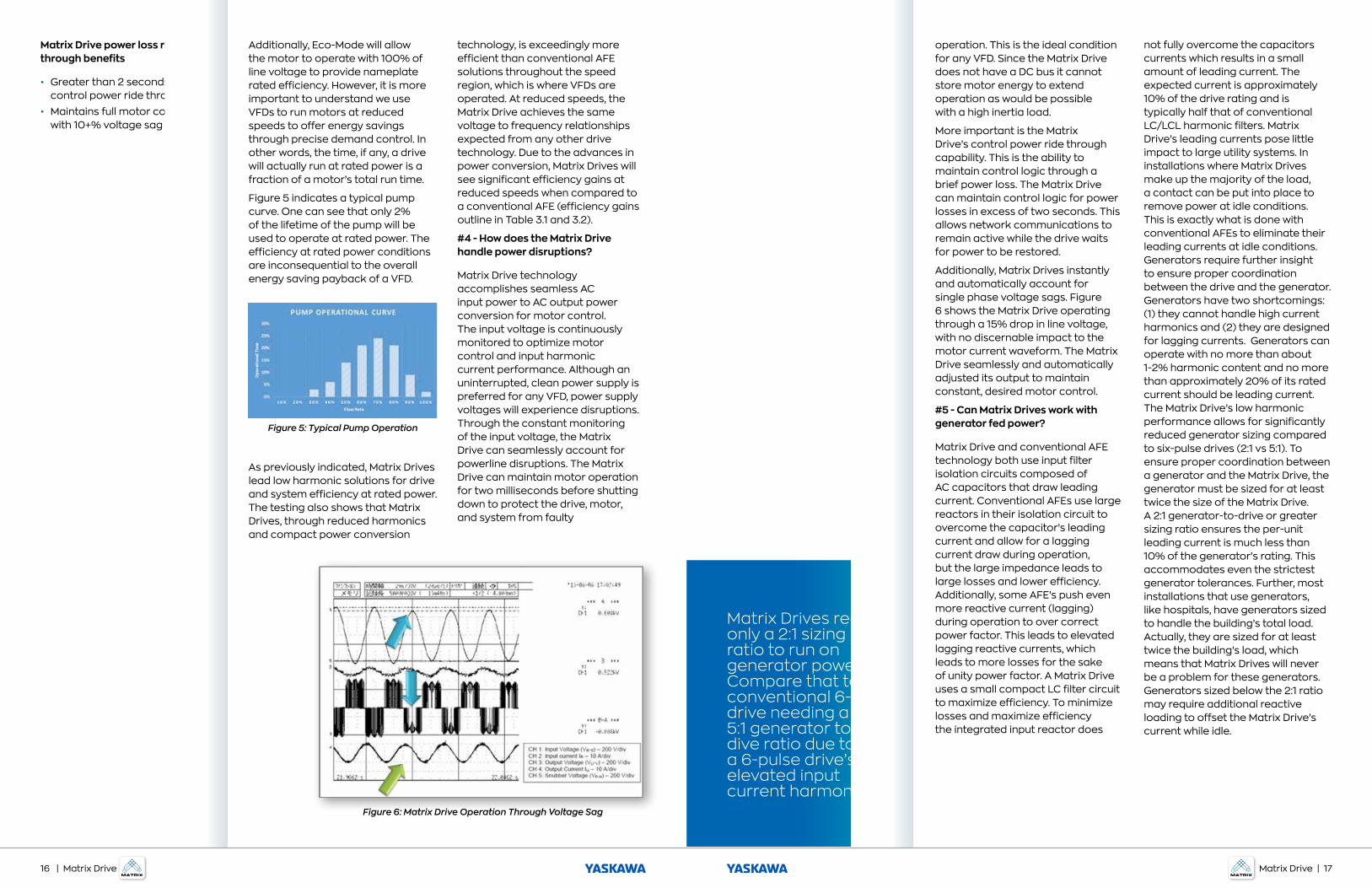
Figure 5 indicates a typical pump curve. One can see that only 2% of the lifetime of the pump will be used to operate at rated power. The efficiency at rated power conditions are inconsequential to the overall energy saving payback of a VFD.
As previously indicated, Matrix Drives lead low harmonic solutions for drive and system efficiency at rated power. The testing also shows that Matrix Drives, through reduced harmonics and compact power conversion
technology, is exceedingly more efficient than conventional AFE solutions throughout the speed region, which is where VFDs are operated. At reduced speeds, the Matrix Drive achieves the same voltage to frequency relationships expected from any other drive technology. Due to the advances in power conversion, Matrix Drives will see significant efficiency gains at reduced speeds when compared to a conventional AFE (efficiency gains outline in Table 3.1 and 3.2).
#4 - How does the Matrix Drive handle power disruptions?
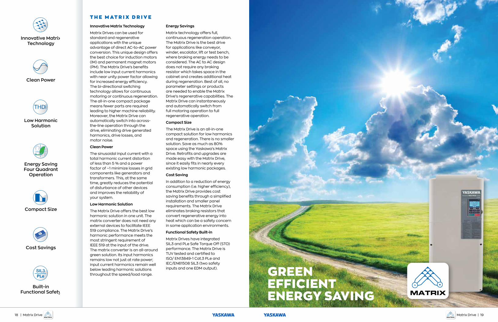
Matrix Drive technology accomplishes seamless AC input power to AC output power conversion for motor control. The input voltage is continuously monitored to optimize motor control and input harmonic current performance. Although an uninterrupted, clean power supply is preferred for any VFD, power supply voltages will experience disruptions. Through the constant monitoring of the input voltage, the Matrix Drive can seamlessly account for powerline disruptions. The Matrix Drive can maintain motor operation for two milliseconds before shutting down to protect the drive, motor, and system from faulty
Figure 5: Typical Pump Operation
Figure 6: Matrix Drive Operation Through Voltage Sag
Matrix Drive power loss ride-through benefits
• Greater than 2 seconds of control power ride through
• Maintains full motor control with 10+% voltage sag
operation. This is the ideal condition for any VFD. Since the Matrix Drive does not have a DC bus it cannot store motor energy to extend operation as would be possible with a high inertia load.
More important is the Matrix Drive’s control power ride through capability. This is the ability to maintain control logic through a brief power loss. The Matrix Drive can maintain control logic for power losses in excess of two seconds. This allows network communications to remain active while the drive waits for power to be restored.
Additionally, Matrix Drives instantly and automatically account for single phase voltage sags. Figure 6 shows the Matrix Drive operating through a 15% drop in line voltage, with no discernable impact to the motor current waveform. The Matrix Drive seamlessly and automatically adjusted its output to maintain constant, desired motor control.
#5 - Can Matrix Drives work with generator fed power?
Matrix Drive and conventional AFE technology both use input filter isolation circuits composed of AC capacitors that draw leading current. Conventional AFEs use large reactors in their isolation circuit to overcome the capacitor’s leading current and allow for a lagging current draw during operation, but the large impedance leads to large losses and lower efficiency. Additionally, some AFE’s push even more reactive current (lagging) during operation to over correct power factor. This leads to elevated lagging reactive currents, which leads to more losses for the sake of unity power factor. A Matrix Drive uses a small compact LC filter circuit to maximize efficiency. To minimize losses and maximize efficiency the integrated input reactor does
not fully overcome the capacitors currents which results in a small amount of leading current. The expected current is approximately 10% of the drive rating and is typically half that of conventional LC/LCL harmonic filters. Matrix Drive’s leading currents pose little impact to large utility systems. In installations where Matrix Drives make up the majority of the load, a contact can be put into place to remove power at idle conditions. This is exactly what is done with conventional AFEs to eliminate their leading currents at idle conditions. Generators require further insight to ensure proper coordination between the drive and the generator. Generators have two shortcomings: (1) they cannot handle high current harmonics and (2) they are designed for lagging currents. Generators can operate with no more than about 1-2% harmonic content and no more than approximately 20% of its rated current should be leading current. The Matrix Drive’s low harmonic performance allows for significantly reduced generator sizing compared to six-pulse drives (2:1 vs 5:1). To ensure proper coordination between a generator and the Matrix Drive, the generator must be sized for at least twice the size of the Matrix Drive. A 2:1 generator-to-drive or greater sizing ratio ensures the per-unit leading current is much less than 10% of the generator’s rating. This accommodates even the strictest generator tolerances. Further, most installations that use generators, like hospitals, have generators sized to handle the building’s total load. Actually, they are sized for at least twice the building’s load, which means that Matrix Drives will never be a problem for these generators. Generators sized below the 2:1 ratio may require additional reactive loading to offset the Matrix Drive’s current while idle.
Matrix Drives require only a 2:1 sizing ratio to run on generator power. Compare that to a conventional 6-pulse drive needing a 5:1 generator to dive ratio due to a 6-pulse drive’s elevated input current harmonics.
16 | Matrix Drive Matrix Drive | 17
GREENEFFICIENTENERGY SAVING
T H E M AT R I X D R I V E
Innovative Matrix Technology
Matrix Drives can be used for standard and regenerative applications with the unique advantage of direct AC-to-AC power conversion. This unique design offers the best choice for induction motors (IM) and permanent magnet motors (PM). The Matrix Drive’s benefits include low input current harmonics with near unity power factor allowing for increased energy efficiency. The bi-directional switching technology allows for continuous motoring or continuous regeneration. The all-in-one compact package means fewer parts are required leading to higher machine reliability. Moreover, the Matrix Drive can automatically switch into across-the-line operation through the drive, eliminating drive generated harmonics, drive losses, and motor noise.
Clean Power
The sinusoidal input current with a total harmonic current distortion of less than 5 % and a power factor of ~1 minimize losses in grid components like generators and transformers. This, at the same time, greatly reduces the potential of disturbance of other devices and improves the reliability of your system.
Low Harmonic Solution
The Matrix Drive offers the best low harmonic solution in one unit. The matrix converter does not need any external devices to facilitate IEEE 519 compliance. The Matrix Drive’s harmonic performance meets the most stringent requirement of IEEE 519 at the input of the drive. The matrix converter is an all-around green solution. Its input harmonics remains low not just at rate power; input current harmonics remain well below leading harmonic solutions throughout the speed/load range.
Energy Savings
Matrix technology offers full, continuous regeneration operation. The Matrix Drive is the best drive for applications like conveyor, winder, escalator, lift or test bench, where braking energy needs to be considered. The AC to AC design does not require any braking resistor which takes space in the cabinet and creates additional heat during regeneration. Best of all, no parameter settings or products are needed to enable the Matrix Drive‘s regenerative capabilities. The Matrix Drive can instantaneously and automatically switch from full motoring operation to full regenerative operation.
Compact Size
The Matrix Drive is an all-in-one compact solution for low harmonics and regeneration. There is no smaller solution. Save as much as 80% space using the Yaskawa’s Matrix Drive. Retrofits and upgrades are made easy with the Matrix Drive, since it easily fits in nearly every existing low harmonic packages.
Cost Saving
In addition to a reduction of energy consumption (i.e. higher efficiency), the Matrix Drive provides cost saving benefits through a simplified installation and smaller panel requirements. The Matrix Drive eliminates braking resistors that convert regenerative energy into heat which can be a safety concern in some application environments.
Functional Safety Built-in
Matrix Drives have integrated SIL3 and PLe Safe Torque Off (STO) performance. The Matrix Drive is TUV tested and certified to ISO/ EN13849-1 Cat.3 PLe and IEC/EN61508 SIL3 (two safety inputs and one EDM output).
Innovative Matrix Technology
Clean Power
Low Harmonic Solution
Energy Saving Four Quadrant
Operation
Compact Size
Cost Savings
PLe
Built-in Functional Safety
18 | Matrix Drive Matrix Drive | 19
TOTALSYSTEM
SOLUTION
Yaskawa is the leading global manufacturer of low and medium voltage variable frequency drives, servo systems, machine controllers and industrial
robots. Our standard products, as well as tailor-made solutions, are well known and have a high reputation for outstanding quality and reliability.
Y A S K A WA . C O M
YASKAWA AMERICA, INC. | Drives & Motion Division
1-800-YASKAWA | Email: [email protected] | yaskawa.com
Document No. WP.AFD.31 | © 2020 Yaskawa America, Inc.