MATRIX ASIIIIKA - World Radio History
76
MATRIX TV RADIO ASIIIIKA MOTOR SPEED CONTROL E FILTER ',Me CT YAMAHA AMP REVIEW HI FI CONSTRUCTION COMMUNICATIONS DEVELOPMENTS
Transcript of MATRIX ASIIIIKA - World Radio History

MATRIX TV
RADIO ASIIIIKA MOTOR SPEED CONTROL
E FILTER ',Me CT
YAMAHA AMP REVIEW HI FI CONSTRUCTION COMMUNICATIONS DEVELOPMENTS

Over ISO ways to
engineer a better future
find out how in just 2 minutes
That's how long it will take you to NI in the coupon. Mail it today and we'll send you full details and a free book. We have successfully trained thousands of men at home - equipped them for higher pay and better, more interesting jobs. We can do as much for YOU. A low- cost home study course gets results fast - makes learning easier and something to look forward to. There are no books to buy and you can pay -as -you -learn.
Why not do the thing that really interests you? Without losing a day's pay, you could quietly turn yourself into something of an expert. Complete the coupon (or write if you prefer not to cut the page). No obligation and nobody will call on you ... but it could be the best thing you ever did.
Others have done it, so can you "Yesterday I received a letter from the institution informing that my application for Associate Membership had been approved. I can honestly say that this has
been the best value for money I have ever obtained, a view echoed by two colleagues who recently commenced the course". - Student D.I.B., Yorks. "Completing your course, meant going from a job I detested to a job that I
love, with unlimited prospects". - Student J.A.O. Dublin. "My training quickly changed my earning capacity and, in the next few years, my earnings increased fourfold". - Student C.C.P., Bucks.
F1N0 GY/TFAR YOURS'ELF These letters, and there are many more on file at Aldermaston College, speak of the rewards that come to the man who has given himself the specialised know- how employers seek. There's no surer way of getting ahead or of opening up new opportunities for yourself. It will cost you a stamp to find out how we can help you. Write to Aldermaston College, Dept. BE180, Reading RG7 4PF, Home of B.1.E.T.
Practical Radio Ft Electronics Certificate course includes a
learn while you build 3 transistor radio kit. Everything you need to know
about Radio & Electronics maintenance and repairs for a spare time income a n d
a career for a
better future. ---CUTOUT THIS COUPON_ -lam ama mi
Tick or state subject of interest. Post to address below.
MECHANICAL Man. Prod.-cent. Motor Mechanics o Society of Storekeeping Auto Diesel Eng. o
Engineers- Management Garage M'ment. o A.M.S.E. (Meth) Skills AEC Aero Eng-
Institute of Quality Control ineering Exams o Engineer & Gen. Aero Eng. o Technicians
CITY & GUILDS DRAUGHTSMANSHIP CONSTRUCTIONAL Gen Mech. Eng. Maintenance Eng.
Institute of Engineering
Institute of Building L.I.O.B. o
Welding Gen. Diesel Eng.
D Designers (A.M.I.E.D)
A.B.T. Clerk of Works o
Sheet Metal Work General Construction Eng. Inspection D Draughtsmanship o Surveyors Institute Eng. Metallurgy D Elec. Draughtsman- L.C.S.I.
ship CITY & GUILDS
ELECTRICAL & ELECTRONIC CITY & GUILDS Gen. Electrical
Architectural Draughtsmanship
Technical Drawing
General Building (all branches) o
Heating & Vent. o I nst. Clerk of
Works Engineering Site Surveying
Electrical Health Engineering Installations
Electrical Maths G
D RADIO & TELE- Road Construction Quantities
Computer COMMUNICATIONS Estimates Electronics fl CITY & GUILDS Hydraulics
Electronic Eng. Telecoms. D Structural Eng. El Practical Radio Gen. Radio & TV
& Electronics Eng. (with kit) Radio Amateur GENERAL
Exam D Agricultural Eng. o MANAGEMENT & Radio Servicing Council of Eng. PRODUCTION Institutions o Institute of Cost Farm Science
& management Plastics D Accnts. AUTOMOBILE &
Computer AERONAUTICAL Programming Institute of the
G.C.E. Works M'ment. Work Study
Motor Industry A.M.I.I.
Gen. Production Eng.
MAA Ci CITY & GUILDS 58 '0' & 'A'
Estimating & Auto Eng. LEVELS SUBJECTS Planning O Gen. Auto Eng.
Coaching for many major exams. including O.VC, C & G, etc.
Over 10,000 group passes
POST -TODAY FOR A BETTERTOMORROW
To Aldermaston College, Dept. BE180, Reading RG7 4PF.
NAME_____ .................... Block Capitals Please ADDRESS ................._.........
QN ( BE180
OTHER SUBJECTS_._ ........................._............................._...._...........................AGE.
Accredited by C.A.C.0 Meenher o] A.B.CC
BRITISH INSTITUTE OF ENGINEERING TECHNOLOGY

JANUARY 1975
main features
Vol. 4. No. 1.
MATRIX TV 10
Solid-state picture transmission is progressing
RADIO ASTRONOMY 18
Where do extra -terrestrial signals come from?
SURVEY OF ELECTRONIC KITS 35 A directory of kits available to the amateur
ELECTRONIC SPEED CONTROL FOR MOTORS . 48 Circuits to control different types of motor
ELECTRONICS - IT'S EASY 60 Designing amplifier stages
projects GRAPE'IC ROOM EQUALISER 23 Control the frequency response of your stereo system at nine octave points
RUMBLE FILTER 52
24dB/octave filter gets rid of sub -audible signals and improves hi-fi sound.
product tests YAMAHA CA800 AMPLIFIER 44 An amp that can be switched to either Class A or Class B
news & information NEWS DIGEST 6
PREVIEW OF FEBRUARY'S ETI 32
ELECTRONICS TOMORROW 64
TECH -TIPS 66
69 DX MONITOR
ETI READER OFFERS 15 BC108 transistors for £1.00 36 Electrolytics for £2.50
31
I Cover: A selection of kits available on the U.K. market - details of these and
many more in our Kits Survey starting on page 35.
ELECTRONICS TODAY INERNATIONAL-JANUARY 1975
EDITORIAL &ADVERTISEMENT OFFICE 36, Ebury Street, London SW1W OLW. Tel. 01-730 8282.
HALVOR W. MOORSHEAD Editor ROBERT C. EVANS Advertisement Manager
STEVE BRAIDWOOD Assistant Editor JEAN BELL Production HELEN COHEN Administration
International Editions COLLYN RIVERS Editorial Director
Australia BRIAN CHAPMAN Technical Editor BARRY WILKINSON Engineering Manager
France DENIS JACOB Editor -in -chief CHRISTIAN DARTEVELLE Editor
Published by: Modern Magazines (Holdings) Ltd 36, Ebury Street, London SW1W OLW.
Electronics Today International is published on the third Friday in the month prior to the cover date. Distributed by: Argus Distribution Ltd. Printed by: Alabaster Passmore & Sons Ltd.
London and Maidstone.
International Associates: Australia: Modern Magazines (Holdings) Ltd, Ryrie House, 15 Boundary Street, Rushcutters Bay 2011, Sydney, Australia. France: Electroniques Pour Vous International, 17 Rue de Buci, Paris, France. USA: ACP, Room 401, 1501 Broadway, New York, USA. European News Bureau: H. Dvoretsky, Manager, 107 Fleet Street, London EC4.
CORRESPONDENCE: Readers queries can only be answered if they relate to recent articles published In the magazine and must be accompanied by a stamped, self-addressed envelope. We are rarely able to provide information in addition to that published. Answers may be subject to delays at certain times due to the production schedule of the magazine. BACK NUMBERS: Back numbers of many issues are available for 30p each plus lop postage. SUBSCRIPTIONS: Great Britain, £3.60 per year, Overseas, £4.00 per year. COPYRIGHT: All material is subject to World- wide Copyright protection. All reasonable care is taken in the preparation of the magazine to ensure accuracy but ETI cannot be held responsible for it legally. Where errors do occur, a correction will be printed as soon as possible afterwards in the magazine.
Now -two fascinating ways to enjoy saving money!
NEW! Sinclair Scientific kit
Britain's most original calculator now in kit form The Sinclair Scientific is an altogether remarkable calculator.
It offers logs, trig, and true scientific notation over a 200 -decade range - features normally found only on calculators costing around £100 or more.
Yet even ready -built, the Sinclair Scientific costs a mere £32.35 (including VAT).
And as a kit it costs under £20!
Forget slide rules and four -figure tables! With the functions available on the Scientific keyboard, you can handle directly
sin and arcsin, cos and arccos, tan and arctan, automatic squaring and doubting, log 10,antiloglo, giving quick access to xv (including square and other roots), plus, of course, addition, subtraction, multiplication, division, and any calculations based on them.
In fact, virtually all complex scientific or mathematical calculations can be handled with ease.
So is the Scientific difficult to assemble? No. Powerful though it is, the Sinclair Scientific is a model of tidy engineering.
All parts are supplied - all you need provide is a soldering iron and a pair of cutters. Complete step-by-step instructions are provided, and our Service Department will back you throughout if you've any queries or problems.
Of course, we'll happilysupply the Scientific or the Cambridge already built, if you prefer - they're still exceptional value.
1.;
Components for Scientific kit (illustrated)
1. Coil 2. LSI chip 3. Interface chips 4. Case mouldings, with buttons,
windows and light -up display in position
5. Printed circuit board 6. Keyboard panel 7. Electronic components pack
(diodes, resistors, capacitors, etc.) 8. Battery assembly and on/off switch 9. Soft carrying wallet
10. Comprehensive instructions for use
Assembly time is about 3 hours.
Features of the Sinclair Scientific
lrad sinclair I^ 10
Scientific e n
IIIIIN IIIIIIIn1INIIIIIIIIIIIIIIKBII.I.IIIII.IIIIhhhlIIn E.:..1....r¡....s:r 3 .........::::as!:iiii.. ....,
572958° 2.30259 2-71828 3.14159
arccos
12 functions on simple keyboard Basic logs and trig functions (and their inverses), all from a keyboard as simple as a
normal arithmetic calculator's. 'Upper and lower case' operation means basic arithmetic keys each have two extra functions.
Scientific notation Display shows 5 -digit mantissa, 2 -digit exponent, both signable.
200 -decade range 10-99 to 10'99
Reverse Polish logic Post -fixed operators allow chain calculations of unlimited length - eliminate need for an = button.
25 -hour battery life 4 AAA manganese alkaline batteries (e.g. MN 2400) give
25 hours continuous use. Complete independence from
external power.
Genuinely pocketable 41/3"x2'x11;16". Weight 4 oz. Attractively styled in grey, blue and
white.
4 ELECTRONICS TODAY INTERNATIONAL-JANUARY 1975

Sinclair Cambridge kit
At its new low price, the original Sinclair Cambridge kit remains unbeatable value In less than a year, the Cambridge has become Britain's most popular pocket calculator. It's not surprising. Check the features below - then ask yourself what other pocket calculator offers such a powerful package at such a reasonable price.
Components for Cambridge kit 1. Coil 2. LSI chip 3. Interface chip 4. Thick film resistor pack 5. Case mouldings, with buttons,
window and light -up display in position
6. Printed circuit board 7. Keyboard panel 8. Electronic components pack
(diodes, resistors, capacitors, transistor)
9. Battery clips and on/off switch 10. Soft wallet
Assembly time is about 3 hours.
Features of the Sinclair Cambridge Uniquely handy package,
4 1/3' x 2" x 11/16", weight 3 1 /2 oz.
Standard keyboard, All you need for complex calculations.
Clear -last -entry feature.
Fully -floating decimal point.
Algebraic logic.
Four operators (+, , x, -- ), with constant on all four.
Powerful constant with separate 'K' button.
Constant and algebraic logic combine to act as a limited memory, allowing complex calculations on a calculator costing less than £15.
Calculates to 8 significant digits
Clear, bright 8 -digit display.
Operates for weeks on four AAA batteries.
Take advantage of this money -back, no -risk offer today The Sinclair Cambridge and Scientific kits are fully guaranteed. Return either kit within 10 days, and we'll refund your money without question.
All parts are tested and checked before despatch - and we guarantee any correctly -assembled calculator for one year. (This guarantee also applies to calculators supplied in built form.)
Simply fill in the preferential order form below and slip it in the post today.
Scientific Price in kit form £19.95 inc. VAT. Price built £32.35 inc. VAT. Cambridge Price in kit form £14.95 inc. VAT. Price built £21.55 inc. VAT.
-1 To : Sinclair Radionics Ltd, FREEPOST,Stives, Huntingdon, Cambs. PE174BR
Please send me Li Sinclair Scientific kit at £19.95 FT Sinclair Scientific built at £32.35 -1 Sinclair Cambridge kit at £14.95 E Sinclair Cambridge built at £21.55 All prices include 8% VAT.
*I enclose a cheque for £ made out to Sinclair Radionics Ltd, and crossed.
*Please debit my *Barclaycard/ Access account. Account number
*Delete as required.
Signed
Name
Address
Please print. FREEPOST-no stamp needed.
L ETI/1 /75_J
inclair Sinclair Radionics Ltd, FREEPOST,St Ives, Huntingdon, Cambs. PE174BR.
Reg. No: 699483 England. VAT Reg. No:21 3 8170 88.
ELECTRONICS TODAY INTERNATIONAL-JANUARY 1975 5

,.-news est NEW DIGITAL MULTIMETER FROM SINCLAIR
Replacing the DM1, one of the first digital multimeters, Sinclair have introduced the DM2, a much improved model for £59 plus VAT.
The designers have carefully thought out the needs of the user. Multimeters are dropped; we know they shouldn't be but that's life so they have gone for a thick aluminium case, not plastic. The unit is powered by an integral PP9 battery for portable use (60 hours life) but an external mains power supply is also available. For normal overloads, built-in protection is provided but for gross overload there is fuse protection.
Input impedance, even on low voltage ranges is 10M2. The actual ranges can be seen clearly on the photograph. Basic accuracy is 0.4% - very much better than even excellent analogue meters.
The display is large, made up from 0.3" 7 -segment displays. Designed around a custom -designed MOS I.C., the DM2 utilises dual scope integration and features high operational repeatability and reliability.
A chain of high stability resistors are used in perference to presets: this improves stability and reduces setting -up costs. Optional extras are a carrying case(E5.00 + VAT) and mains converter (f 1.85 + VAT). The DM2 weighs 1kg and measures 9" x 6" x 2" plus handle.
Sinclair Radionics, St. Ives, Huntingdon, Cambridgeshire.
PERSONAL ALARM SYSTEM All Americans may soon carry a
wristwatch -sized personal security alarm!
The US Law Enforcement Assistance Administration has commissioned the Aerospace Corporation to launch a massive field test next year of a prototype system that may eventually become nation-wide.
The system is based on thick -film hybrid UHF modulated transmitters which may eventually be built into standard electronic watches.
To generate an alarm, the wearer presses two buttons simultaneously. This causes an internal shift register
generate a digital code which in toturn
frequency modulates the transmitter.
The alarm signal is then picked up by the nearest of a vast number of
local receivers which retransmits the signal together with data identifying the transmitter's locationm to a
central processing computer in the local police headquarters.
In the forthcoming field trials, some 5000 alarm units will be used.
SCHOOLS' LINK TO INDUSTRY We received an interesting newsletter from the organisers of the "Link Scheme" They are a service for school teachers complimentary to that of the National Centre for School Technology. Help is offered regarding technical data, component distributors or technical advice, by means of a
"Hot Line" phone number. The scheme's newsletter prints comments on recent issues of electronics. magazines and provides additional information for school teachers. Also there is an evaluation of magazine
projects which have been built up by grammar school pupils. Their scheme has a contact man who will be arranging to visit schools to see what assistance a contact in industry can be to a school teacher.
If you are an interested teacher we suggest you get more details from Peter Noakes at the University of Essex Department of Engineering and Science, Wivenhoe Park, Colchester, CO4 3SQ.
200 MILLION DEGREES! An important advance in work on nuclear fusion is reported by scientists at the University of Texas, Austin. Dr. William E. Drummond, director of the university's fusion research centre, says that a
temperature of more than 200 million degrees Centigrade has been attained for some 50 micro -seconds in the centre's Tokamak -type unit by turbulent heating of the plasma, a
new technique developed at Texas and in the U.K.
PCB MOUNTING PILLARS
The Ilex pillars are designed to insulate printed circuit boards from the chassis and at the same time to support them. One PCB can be stacked on another (either vertically or horizontally).
Now the experimenter can easily mount a PCB to a chassis, a PCB to a
PCB, or a screen to a PCB using Hex, completely dispensing with nuts or screws.
The pillars are made in moulded nylon, and have a rigid girder -shaped supporting section, a spring -in fastening at the top and at the base constant bending springs together with 3 push -in clip (giving a wide thickness tolerance which ensures an equally tight fit to any thickness from 1/32" to 1/8"). A firm grip by the Hex into the upper board can be obtained with a 4 mm hole, and because it is insulating, it can quite safely be close to the conductors. At the base a 4.8 mm hole is needed.
Ilex come in heights of'/4",'/2", 3/4', 1" and 1'/2". The half inch size costs 3p each for 10 off, dropping to 1.2p each in lots of 10,000 off. From West Hyde Developments Limited, Ryefield Crescent, Northwood Hills, Middlesex, HA6 1 NN.
6

STATIC 4k MEMORY For some time now, efforts have been made to increase the integration density of static memories. In the Siemens Research Laboratories a static MOS memory has been produced accommodating 4000 bits on 14.7mm2.
The memory is an integrated circuit in aluminium gate ESFI technology. This step forward was made possible by integrating the switching elements on an in- sulating substrate and employing a non -crossing conductor layout between the transistors and resistors in a memory cell.
An initial breakthrough on the way towards static ESFI MOS memory cells (ESFI = epitaxial silicon film on insulators) of high packing density was the development of a complementary MOS cell with five transistors and an area of 4000µm2. The second measure was to combine two complementary transistors and two load transistors in one cell in a non -crossing layout to obtain a flip-flop. In this way, the cell area was reduced to 2000µm2. The final step was to re- place the select transistor by a diode and to use the power supply lines. It was thus possible to reduce the memory cell area again to 15001.2m2. This is even less than the area required by MOS memories and bipolar memory cells.
The chip measuring 4.2mm x 3.5mm contains the actual memory matrix, the word line decoder (on the left), the bit line decoder (at the bottom) and the read-out circuit (bottom left-hand corner).
Such memory cells have already been integrated in a configuration with 4096 bits. The chip area is then 14.7mm2: the actual memory matrix, the word and bit line decoders and the read-out circuit are accommodated in an area measuring 4.2mm x 3.5mm. The results of tests allow us to predict an access time of around 120nS and a cycle time of about 170nS for the product- ion module. The power dissipation is 100mW. w w
o
M
4000//m2 (6.4 mi12): circuit of a conventional flip-flop memory cell with two p -channel and two n - channel transistors and a select transistor TS in ESFI MOS technology.
2000µm2 (3.2 mil2): circuit of the new memory cell made in the Siemens Research Laboratories. One of the p -channel and one of the n -channel resistors was replaced by a high -valued resistor R. The size of this flip-flop in non -crossing conductor layout has been halved.
1500/1,112 (2.4 mil2): This further reduction in area has been obtained by replacing the select trans- istor TS by diode D.
Supply Voltage: VDD word lines: W & Wl & W2 bit lines: B chassis ground: 0 V
QUAD OP -AMP: LM324 SDS Components Ltd have available an interesting quad op -amp which is
unusual in that the input common mode voltage range includes ground even when the amplifier is operated from a single supply rail. In addition, also under single -rail supply conditions, the output voltage swing includes ground. The device is the Signetics LM324. The current drain (800µA) is essentially independent of supply voltage over the range 3 to 30V or ±1.5 to ±15V. Power consumption works out at about 1mW per op -amp when a 5V supply is used.
The devices feature internal frequency and temperature compen- sation, and each op -amp has a unity gain bandwidth of 1MHz, a common mode rejection ratio (d.c.) of 85dB and a power supply rejection ratio of 100dB. Open loop gain at d.c. is
100dB while coupling between amplifiers is -120dB.
Differential input voltages equal in value to the power supply voltage can be applied without fear of damage. Bias current and input offset voltage and current are all very low at 45nA, 2mV and 5nA respectively. The input bias current is temperature compensated. At the 100 up rate, the cost is £1
(25p per dual -in -line package). Designed for operation over the industrial temperature range of 0 to 700C, the LM324 is a general-purpose quad operational amplifier of good per- formance for use in industrial, automtove and other similar applications.
SDS Components Ltd, Hilsea Trading Estate, Portsmouth, Hants, P03 5JW.
PUSHBUTTON POTENTIOMETER Bourns new Model 3680 KNOBPOT Digital Potentiometer combines a
precision incremental decade potentio- meter with an easy -to -read digital display, and fast, pushbutton resistance selection all in one integral package, with snap -in -mounting.
This device is ideal for use where Panel designs involve data entry or set -point controls. Bourns' unique design combines precision laser - trimmed cermet resistor technology with a pushbutton detent action. Resolution of the output is 1 in 1000 discrete steps, and repeatability of ±0.1%. Each decade has a rated life of 100,000 operations. The specificat- ion gives a power rating of 2W, a
standard resistance range of 3 -decade units (5KS2 to 1M2), and a resistance tolerance of ±1.0%.
Bourns (Trimpot) Ltd., Hodford House, High Street, Hounslow, Middlesex TW3 1TE. ,J

news digest DIL PCB SWITCH Ten new types of dual -in -line PCB programming switches are now avail- able. Contact arrangements include 1 pole 8 way and 4 independent changeover contacts with bbm action. The gold on nickel contact surfaces give in excess of 20,000 switching
steps at the full rated load of 30VDC 250mA. Applications include BCD setting, select on test, range attenuation and cross point switching.
From ERG Limited, Luton Road, Dunstable, Beds.
GRAVITY WAVE DATA TRANSMISSIONS? Future communications systems could well utilize modulated gravity waves propogating directly through the centre of the earth - according to a report given recently to the British Association by Dr. Dreyer of the Dept of Natural Philosphy, Glasgow University.
The notion is very much on the border -line between physics and science fiction as great controversy still continues as to whether gravity waves exist or not, however modern theory increasingly supports the idea of energy waves flowing across the universe in the way that light energy flows from the gigantic energetic disturbances in stars and galaxies.
MAGNETIC -ELECTRIC INTERCONVERSION Philips Research Laboratories in Eindhoven have developed a
composite piezo-magnetic/piezo- electric material that inter -converts magnetic and electrical fields.
The actual material is composed of a molten eutectic mixture of barium titanate and cobalt ferrite which is
solidified uni -directionally. Conversion is brought about by
mechanical deformation hence optimum efficiency occurs at the mechanical resonant frequency.
8
The photo shows a model of the GEC -Marconi Minitram which was produced as a result of work on a competitive contract for the Transport and Road Research Laboratory to define the development necessary for a proposed system in Sheffield. The work included the design of the vehicle itself, the track on which it would run and the control system for its operation.
There is of course nothing new in magnetic and electrical inter - conversion. It is achieved for instance in a solenoid. What is unique about Philips' new material is that conversion takes place without a flow of current.
They might look like date stamps but in fact they are new aluminium elect- rolytic capacitors.
They are made by AEG-Telefunken and coded EFT. The capacitors feature low dissipation, low impedance and good temperature characteristics. Intended for AC operation without polarized voltage DC, these compo- nents are especially suitable for the audio -frequency load in dividing net- works of loudspeaker -cabinet& They come in ratings from 2.2µF to 100µF and -voltages of 40V and 63V DC as well as 15V and 23V AC.
ELECTRONIC BALANCE This first product from Shinko Denshi of Tokyo launched on the British market is the Digipet top -loading automatic electronic weighing machine with digital display. This is a compact precision weighing machine with measuring ranges of 0-19.99gm and 0-199.9gm; the required range is
set automatically to provide an accuracy of two decimal places for weights under 20gm and one decimal place for objects over 20gm. Overload is set at 250gm.
The elctromagnetic weighing mechanism automatically resets to zero within 0.15 sec and the digital meter can be switched to give a read- out within either 0.5 or 1.5 sec. Facilities are provided for automatic tare compensation, and BCD, TTL- compatible digital outputs or 5-V analogue outputs are provided for recorders, printers, comparators and computers. Supplied by Transducers (CEL) Limited, Trafford Road, Reading, R61 8JH.
Continued on page 70.id

MK50250N Alarm Clock IC . . . . £6.90 CT7001 Alarm/Date IC . ..... £9.80 We have developed some new circuits for using these I.C.'s with various displays.
MK50250N plus 4xDL704 . . . . £10.20 plus 6xDL704 . . . . £12.10
You can now build a high quality 0.3" LED alarm clock at a reasonable price. High Quality 0.3" LED's. Common Cath. 95p These LED's are manufacturer's prime units, better than the special offer LED's; in a 14 -pin package.
SOLDERCON IC PINS - Affordable Technology Reduce wastage - if you buy 1000 pins you can make an 8 -pin socket for about 3Y2p, a 14 -pin socket for about 6p - Reuse your IC's, DISPLAYS, LM380's etc. Ideal for LED digits and clock chips, anything from 8 -pin to 40 -pin.
Prices per 100 pins 100+ 70p 300+ 50p 1000+ 40p 3000+ 35p
HEAT SHRINK TUBING I /1 6 ", 1 /4 ", 3 /8 ", 12 p per 2 0 cm (any diameter). COMING SOON: 3 digit LED (0.12"high in DIL package for £1.35 (4 5 p per digit) DIGITAL WATCH KIT: £55. Send for details ADD 8% VAT 10p p&p for orders under £2.
SINTEL,53a Aston St., Oxford. Tel:0865 43203
or send s.a.e. for sample and instructions
SPECIAL XMAS OfFER!! FOR THIS MONTH ONLY: CALCULATORS
SINCLAIR TEXAS Cambridge £17.25 TI -1500 £26.25 Cambridge Memory £24.95 TI -2000 £13.95 Scientific £24.95 TI -2500 £19.95 Executive £24.95 TI -2550 £29.95 Executive Memory £28.95 SR -10 £32.00 BC107 10 BC212 12 T1P29A 50 709 8pn OIL 36 BC108 10 BC213 12 TIP30A 55 709 TO99 36 BC109 10 BC214 12 TIP41A 85 711 TO99 50 BC177 22 BC212L 12 TIP42A 90 741 TO99 38 BC178 24 BC213L 12 TIP2955 90 741 8pn DIL 37 BC179 24 BC214L 12 TIP3055 56 741 14pnOIL39 BC182 10 BCY70 15 TIS43 25 747 14pnOIL96 BC183 10 BCV71 16 T1S74 65 748 8pn DIL 39 BC184 10 BCY72 17 ZTX304 26 SL301B 75 BC182L 10 BFY50 18 ZTXSO4 34 IC SOCKETS BC183L 10 8FY51 18 2N3053 16 8 pin DIL 15 BC184L 10 BFY52 19 2N3055 49 14 pin DIL 15 7400/5 20 7490 66 2N3819 20 16 pin DIL 15 7410 20 7492 70 2N3820 39 Dieeast Boxes 7413 38 7493 66 2N4442 70 4'/zx21/2x1 50p 7420 20 74107 55 0A10 22 41/2x 70p 7430 20 74121 55 0A47 7 71/2x41/2x2 150p 7440 20 74141 1.00 0A70 7 7442 86 74150 2.10 7447 1.30 702 45
ÓA81 0A91
7 6 RESISTORS
7470 34 710 14pn 37 0A200 6 TR5 2% 7472 34 709 14pn 37 0A202 9 All values 7473 45 0C23 50 1N914 5 2.5p 7474 42 0C24 50 1N916 5 7475 60 0C28 60 1N4001 6 WI REWOUND 7476 42 0C29 60 1 N4002 . 6 2.5W 10 7483 1.25 0C35 55 1N4003 7 6W 10 7486 46 0C44 25 1 N4006 "9 9W 12 SOLDER CA3646 80 1N4148 5 15W 15 18 s.w.g. CA3028 99 Disc Ceramics ZENERS £1.80/1/2 kilo CA3026 75 All values 3p 400mW 12p
P.E.C. 49-51 St. Mary's Road, Oatlands Village, Weybridge, Surrey KT13 9PX. Tel. Walton 21324 or Weybridge 51907 (evenings)
ALL PRICES INCLUDE VAT CWO. MAIL ORDER ONLY
Telephone Orders
Hay r.arkxime accepted from ACCESS holders
P & P 15p - FREE over £3.00
We thought the fantastic offer with 7 segment LED displays would be popular. But the response was shattering. Our apologies to those of you who didn't get the devices as quickly as you, or we, would have liked - but we were slightly overwhelmed. Anyway, we have still got devices available, so if you want some D L704, 5 for £3.25 inc. VAT & pp - please send the coupon from September ETI. Otherwise, they will cost you £5.00 for five, After all, special offers have to be special - nonetheless, this is still terrific value.
Don't forget we do things like TTL, PLL, TOKO coils and filters, lots of linears. And don't forget we know more about using our devices than any other enthusiast orientated supplier. Try us, and see.
First step is to get our catalogue - 25p, refundable with £5 worth of goods. Here's a very brief selection: NE560/1/2B £3.19 ICL8038CC £3.10 LM381N £1.85 TOKO EF5603 Tuner £8.40 CFS10,7 (sim FM4) 40p NE565A £2.75 CA3089E £1.90 MC131 OP £2.80 CFT AM ceramic filters 45p NE566V £2.55 CA3123E £1.40 CT7001 £10.00 MFH mechanical filters £1.35 NE567V £2.75 LM380 £1.00, TIP3055/2955 pair £1.50 7447 £1.45 7490 65p
VAT EXTRA POST AND PACKING 15p ACCESS WELCOME All goods are brand new marked and tested, and available in quantity. Manufacturer enquiries welcome.
37 HIGH STREET, BRËNTINOOD, ESSEX CM14 4RH
ambit Tel: (0277) 216029 Telex: 995194
SAE All enquiries please
INTERNATIONAL. ELECTRONICS TODAY INTERNATIONAL -JANUARY 1975 9

MATRIX TV.a solid-state picture transmission system by Dr. Sydenham
WHEN MAN learned of ways to produce an optical image - probably when he found that a pin -hole in a
screen produced a reduced size picture - he took a great step forward in both understanding and enjoying life.
In 1859 Dionysius Lardner of University College, London wrote in his encyclopaedic "Museum of Science and Art"
"The image of visible objects produced by reflection from smooth or polished surfaces, natural and artificial, and by looking through transparent media, bounded by surfaces having certain curved shapes, play a part so important in the effects of vision, that it must be regarded as highly interesting to explain the optical principles upon which the production of such images depends, so far at least as may be
It ÿ leemee1E+eC7b7éie irideageggeaffiemélfeeem''+7Cetembe5
SAMUEL WHITFORD,
tai
Lj
OPTICAL,
PHILOSOPHICAL,
A N D
MATHEMATICAL-
INSTRUMENT -
MAKER,
(THE ORIGINAL SHOP.)
At the THREE SPECTACLES, N° 27, Ludgate -Street, near St. Paul's, LONDON, /BARES and fells SpcEìacics ofGlafs or Pebble, in neat 'and light Frames,
t1r j of the newcll and belt ConftruEtion, and in the tno(I convenient Manner lar avoiding PrefTure on the Nofe or Temples.
Concaves for very fhort-frghted Perlons; and Glaffcs for reading, magnifying, and burning.
Reflecting Telefcopes, of all Kinds, and with the lateft Improvements. Refracting Telcfcopcs of all Sorts; with one of a New Invention (ufeful
for Sea of Land) that will not warp in any Weather; and a Sort to ufe at lea in the Night.
Double, Single, Solar, Opake, or Aquatic Microfcopes. Camera Obtcuras, to delineate Landfcapcs and Profpefts (and which ferve
to view Pcrfpeftive Prints) made truly parallel; Sky -Optic Balls; Prifms, to deuwnHrate the Theory of Light and Colours ; Concave, Convex, and Cylin- drical Speculums; Magical Lanthorns; Opera Glafïes; Optical Machines for Perfpcetive Prints ; Cylinders and Cylindrical Piftures.
Air -Pumps and Air -Fountains of various Kinds; Glafs-Pumps ; Portable Apparatus fur EleEtrical Experiments, which is allowed by the Curious to be the bell of the Kind.
Barometers, Diagonal, Standard, or Portable. Thermometers, llydroflatical Balances, and Hydrometers. Hadlevb gLiadrant, after the molt exaEt Method, with Clarks truly parallel ;
Davis's Q22adrant; Globes of all Sizes ; Compaffes, Azimuths, Steering, and Plain ; Loadllones ; NoEturnal and Sun -dials of all Sorts.
Scales ; Cafes of Drawing-lnftruments ; Parallel Rulers; Proportional Corn - paths, and Drawing Pens.
Theodolites, Semicircles, Circumferenters, Meafuring Wheels, Spirit Levels, Rules, and all Sorts of the bell Black Lead Pencils, and all other Sorts of Inftru- ments of the newell and molt approved Invention. * LANDS accurately furveyed.
^'tli dl j..,ipy w..+!t./Y3Z1410:Y+".iY/.i4li.Ìn'i'!':YuIWGGla Y-.í^V :Y?wi+l3iVGN
c:
Fig. 1. Trade card of Samuel Whitford shows evidence of early links between optical and electrical crafts.
necessary to render intelligible the natural appearances and effects which are familiar to every eye, and innumerable contrivances, from which we derive essential benefit, either in repairing defects of vision, or extending the range of that sense to objects removed beyond its natural limits, either because of their minuteness or remoteness or in fine in producing phenomena affording at once amusement and instruction."
All manner of devices were indeed devised. The microscope, the telescope, the camera obscura, the camera lucida and the magic lantern have been handed down to us.
The science of optical imaging was well developed by the start of the 19th century. For many a decade before this, firms had been proudly advertising their optical wares and expertise in handsheets such as that shown in Fig. 1.
Optical instrument -makers excelled at the crafting of mechanical contrivances so it was natural for them also to take on the manufacture of the then emerging electrical machines.
There were very few of these to begin with - Whitford's sheet mentions "portable apparatus for electrical experiments". But by the mid -19th century, the electrical "curiosities" had expanded in number from simple electrostatic devices to include magnetic ones as well. The feeble oil -lamp powered magic lantern gave way to arc -lamp versions - like that of Mr. Dubosc of Paris (illustrated in Fig. 2). A new science, that of electro -optics,
came into being. But it could not advance much in the 19th century, for hardware capable of converting light into electrical signals was not developed until the 1880's. If an experimenter wished to relay or record images before this time then they had to be copied and conveyed by hand. If several people wished to view the same image they had to take turns, use elementary photographs or manage with a multiple instrument such as Nachet's multiple microscope (shown in Fig. 3.)
In 1895 Becquerel observed that certain substances used as electrolytes in a primary battery cell generated differing voltages if the two plates
10 ELECTRONICS TODAY INTERNATIONAL-JANUARY 1975

Fig. 2. This magic lantern, made about 1855, uses electrics and optics. In those days electric photo diodes did not exist: opto -electronics was a simple -discipline.
were exposed to different light intensities.
A little later, in 1887, Arrherrius found that the resistance of silver halides increases with increasing light level.
In 1905 a photo -electric theory of vision was published and photo -detectors (of cumbersome form) became a more or less routine component available to designers.
By 1920 one could purchase a
potassium -hydride photocell complete with a thermionic valve amplifier. Glazebrook, in his 'Dictionary of Applied Physics' (1922) remarked on this package --
"Used in this way the photo- electric cell may well prove its usefulness not only in photometry but in signalling without wires and as a means of scientific investigation."
He was so right* He also said he was pleased to see that
such an obscure phenomenon was finding increasing use of technical importance.
Single -cell detectors were continually improved, and far greater sensitivity was achieved by devices such as the photo multiplier. A solid-state
*(A future issue of ETI will feature modern electro -optic communication links.)
photo -diode was eventually developed which was not only small but retained a good measure of detectivity.
Single -cell detectors, however, can only measure and transduce the intensity of radiation occurring in a
single -point area. They cannot produce an electrical equivalent signal of two-dimensional images unless some mechanical system is used to enable
Fig. 3. Before closed-circuit television was in vented, multiple viewing had to be under- taken with devices such as Nachet's multiple microscope.
them to scan an area, or a matrix of such photo cells is used.
The first photo cells were bulky so early inventors of two-dimensional image transducing systems were obliged to use mechanical scanning to effectively move the photo cell across the image.
Nipkow devised his spinning disc method of television in 1884; with it successive elements of the picture were viewed one at a time in a sequential pattern.
His work was further developed by Baird, in the 1920's - who pioneered our present-day television systems.
The Nipkow disc, however, was incapable of producing really acceptable picture definition, it was soon replaced by thermionic camera tubes in which an electron beam is
systematically deflected across a
photo -sensitive target on which the image is formed.
Zworykin's "Iconoscope", one of the earliest camera tubes, used a photo sensitive area of fine mica flakes - called the mosaic. These minute cells formed small capacitors that became charged to a level decided by the intensity of the radiation falling on them. The many "cells" were interrogated at regular time intervals by an electron beam scanned across them, monitoring the change in beam current occurring at each cell as they discharged.
As the cells were not being read out continuously it was possible to integrate (or average -out) the charge produced over a period of time, thereby increasing the sensitivity to light. This process is now known as
charge -integration. Today's television picture -tubes are
still similar to the Iconoscope, the differences being in simplification of
ELECTRONICS TODAY INTERNATIONAL-JANUARY 1975 11

MATRIX TV the mica mosaic to give us the relatively inexpensive Vidicon and its derivatives and sometimes to make use of secondary emission which enhances sensitivity in tubes such as the image-orthicon. Thermionic picture tubes have long
provided adequate resolution and linearity for most purposes, and production costs have been reduced to the point where amateur video recording is an increasingly popular hobby.
Nevertheless, thermionic tubes are bulky and thirsty for power compared with the potential capability of the latest solid-state integrated circuit technology. The days of thermionic picture tubes are numbered. Solid-state detection will undoubtedly replace them in the not too distant future - indeed in a few special cases this has already happened.
MATRIX SOLID-STATE DETECTORS
Early photo detectors needed several square centimetres of radiation to produce a useable signal change. Consequently a multiple array used to transduce line or plane optical information was rather large in size. Scanning was much easier to implement in a reasonable space.
Selenium was found to be a
photo -electric substance. Willoughby Smith made resistors of it (in 1873) only to find its ohmic value varied with light intensity - thus adding
LIGHT
PHOTO DIODE
O j SWITCH
- VE
SHIFT REGISTER BIT n+1 (RESET)
another important transducer effect to the growing list!
The- existence of relatively sensitive selenium detectors enabled Ruhmer to study the practicality of matrix array techniques which were connected to a
similar array of lights with paralleled wires. In the period 1901-1912 he tried many ways of producing television by such means. He failed miserably. Selenium cells have a quite long time -constant (many milliseconds) so they were unable to follow transients of moving images.
Experimenters tried to reduce wiring connections by scanning the cells using mechanical switches. A scheme was proposed that needed a 32 -contact wiper switch rotating at 960 rpm; it was dropped because it would also demand lamps that could be flashed at 640 000 times a second "which was manifestly impossible" says the author of the report.
In 1929, a popular -science technical writer (Ellison Hawks), summed up the situation by these remarks:- "Although there are immense difficulties, however, one would like to suggest that the method should not be finally discarded for it is the only one so far suggested by which the whole of the picture can be transmitted at one time".
When semiconductor technology exploded in the 'fifties and 'sixties it became possible to make highly reliable and inexpensive solid-state photo -diodes that were of only pinhead size. Eventually the problems of placing a large number of these side
Fig. 4. (a) Basic photo detection element consists of a diode and a switch. (b) The basic system is ex- tended with a buffer and a switch when the voltage sampling method is used.
SHIFT REGISTER BIT n (READOUT)
VIDEO OUTPUT
by side to form a matrix were overcome and we saw the successful development of lines of detector elements using large-scale integrated circuit production methods.
Some of the "immense difficulties" have been overcome, some still remain.
It is now about ten years since satisfactory integrated detector arrays were first made. Line arrays have been used in military optical missile trackers, and in a few industrial applications. Their widespread use was, however, restricted by cost and by the lack of an adequate density of photo -diodes. Today the diodes can be formed 75 µm apart (less than half the size of a full stop on this page) with a
64 by 64 array being comparatively easy to accomplish.
Such achievement may well seem surprising but the resolution needed for many purposes is already routinely obtained with the 625 line television system - about 3 000 000 picture elements in the picture area.
The massive IBM array still does not compete on a size basis with a good vid icon tube!
To illustrate the technology used, we now take a look at some manufacturing methods and circuit techniques.
THE MATRIX Basically light -detecting photo -diodes
are paired with semiconducting solid-state switches - shown diagrammatically in Fig. 4a. They are made by sequentially depositing metal conducting and semiconducting films on a supporting insulator substrate. This technique gives the designer a high degree of confidence as the majority of devices made in an array will work as expected. It also enables a
variety of components - both active and passive to be produced by the same basic process of depositing films through carefully made screening masks.
The most generally used mode of operation for the photo diode is that of charge -integration.
Using the self -capacitance of the diode, (which is created by the separated metal films), the diode is first charged up with an externally applied voltage source. The associated switch is used firstly to connect the diode to the source - and then to isolate it by effectively opening one connection of the photo diode. Charge in the diode then commences to leak away due to electron leakage within the diode structure and, more dominantly, by electron carriers that are formed by the photons falling on the photo -diode. The charge loss is
12 ELECTRONICS TODAY INTERNATIONAL-JANUARY 1975

then measured, as will be explained later.
The amounts of energy involved are minute. The voltage across the diode decays through 2.5 V (that is, the charge is lost and, therefore, so is the voltage) in an integration period of 10 ms when the incident light level falling on the diode is 0.1 W/m2. This process, due to the tiny area of the diode, involves only 1-10 pC of charge (pC - pico coulombs; the charge of a
single electron is roughly 107 pC and 1
C flowing per second is a current of one ampere). Direct sunlight provides a radiation intensity of around 100 W/m2. The energy involved to "drive" the detector through the 2.6 V swing Is of the order of 10-10 W!
Having devised a scheme to charge the diode and isolate it ready for radiation detection, the next state is to measure the loss of charge, This can be achieved by measuring the voltage across the diode, in which case a
second MOS switch is used to connect the external circuit to the diode. A third MOS component is used to buffer the photo -diode from the load imposed by the sampling switches. This is necessary for without it, the sampling switch will present too low a
resistance to the diode, leaking charge before the correct voltage level can be decided.
This method of measurement is
known as voltage sampling. It is
portrayed diagrammatically in Fig. 4b. The sampling rate for this mode of readout is around 200-500 kHz and it suffers from a somewhat large noise level.
An alternative way to interrogate the diode is by what is known as the recharge -sampling mode. In this the criteria of light -level used is that related to the amount of recharge needed to fully re-establish the voltage across the diode, (Fig. 5). This method needs only the first -mentioned charging switch at the diode location, thus reducing the number of elements needed in the full detector component, but it does require more analogue voltages. But having added this extra circuitry, it then becomes possible to read at 5 MHz multiplexing rates - and the noise Ieiel is much less than with the above described voltage sampling.
The actual manufacturing method used to make an element of the array is typified by the drawing of one such element that is given in Fig. 6. Simplicity of contacts and junctions is
had at the expense of adding more electronic components elsewhere in the data processing. When the array is
made as a single line only it is possible to pack the photo -detecting elements at one third of the spacing, that is at only 25 centres.
Fig. 5. Recharge -sampling readout requires no extra components in the array but produces a pulse height current signal that needs extra processing.
CHARGING LINE
CURRENT PULSE HEIGHTS PROPORTIONAL TO VOLTAGE DECAY
OBTAINING ACCESS TO THE DIODES OF THE ARRAY
Each element has its input and output "terminals" permanently connected to X and Y conducting lines - made with deposited metal film strips.
The arrangement used for the faster recharge -sampling processing method is shown in Fig. 7. The ends of each X and Y line are connected such that each can be connected to a single common line as needed, this happening sequentially. This is achieved by using a continuously operating pulse generator that 'clocks' a solid-state scanning switch - the register - along in steps. This causes a
string of charge pulses to appear on
//z
N -TYPE SUBSTRATE
P -TYPE DIFFUSION
GATE OXIDE
METALLISATION.
CONTACT HOLE
1 vo
ACCESSING I- PULSE
4 REDUCING DUE TO I RADIATION LEVEL
RESET LEVEL
TIME - the output line ready for height processing.
Special consideration has to be given to driving these lines, for several effects, such as large line capacitance, tend to limit the useable scan rate unless used in special ways. IPL, for example, have developed a system whereby the flyback time is eliminated thus utilizing the total time more efficiently.
The shift register scanning switches for the X and Y drives, are also formed on the same chip, placing them around the edges. Figure 7 shows an enlarged view of the top of the 64 x 64 IC which includes both the photo -diode array with its recharge switches and the shift registers. (Most users of such a chip would not wish to have to build
X -LINE R = 0.47
\N.®nk Z.1
1.419i. .
Y -LINE
R IS THE RATIO OF PHOTO -DIODE AREA TO TOTAL ELEMENT AREA -.a---_ 75pm Fig. 6. Photo -diode and switch is manufactured by appropriate diffusion and metallisation on a substrate.
ELECTRONICS TODAY INTERNATIONAL-JANUARY 1975 13

MATRIX TV X -REGISTER TRAVELS THIS WAY - X
SUBSTRATE
ti
DIODE X, Y
SUBSTRATE
their own processing circuits, so a
complete system is offered shown in
Fig. 9. In this are housed the clock pulse generator, signal processing circuits and a means to physically mount the appropriate optical element to produce the right size image.)
X+1
Y -LINE
Fig. 7. Typical section of a two-dimensional array using recharge -sampling.
Y -R EG ISTE R
TRAVELS THIS WAY
Y
Y+1
After preamplification, the recharge pulses appearing on the output line are
integrated (rather than peak detected) and applied to a circuit that samples them and holds their level for outputing. as a closely analogue -varying signal.
Fig. 8. Integrated Photomatrix Ltd.'s 64 x 64 photo -diode array. The central chip is barely 6 mm square.
Fig. 9. At present the processing circuits of the complete matrix camera require more room than the array (lower centre) but this is largely due to the need to custom build this part of the system.
ARRAY OUTPUT
VIDEO OUTPUT
SIGNAL PROCESSOR
APPLICATIONS OF MATRIX ARRAYS
Arrays containing only 4096 picture points ("pixels" is a term sometimes used) cannot compete with vidicon television picture tubes on a resolution basis.
Neverthless, there are many applications where an array is superior and/or where the full resolution. capability of the thermionic camera tube is not required.
Flaw detection - unwanted pin holes in, say, tape or films can be easily detected using a single photo detector to look for light coming through from a source mounted below. This basic method, however, is limited by non -uniformity of the background
14 ELECTRONICS TODAY INTERNATIONAL-JANUARY 1975
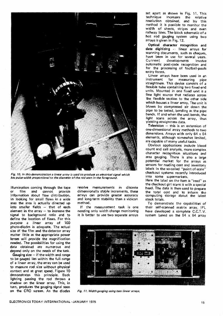
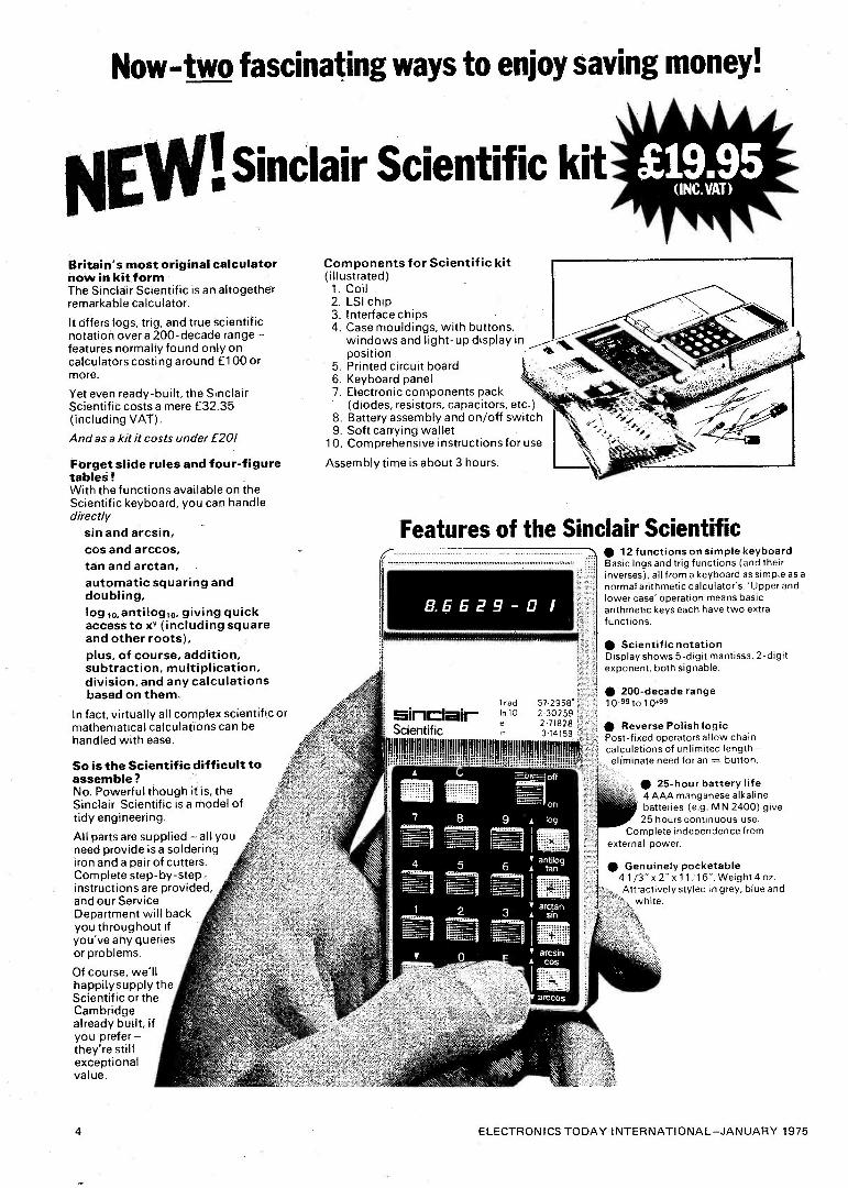
Fig. 10. In this demonstration a linear array is used to produce an electrical signal which has pulse -width proportional to the diameter of the rod seen in the foreground.
illumination coming through the tape or film and cannot provide information about flaw distribution. In looking for small flaws in a wide area the area is actually directed up into smaller fields - that of each element in the array - to increase the signal to background ratio and to define the location of flaws. For this purpose a linear array of 100 photo -diodes is adequate. The actual size of the film and the detector array matter little as the appropriate power lenses will provide the magnification needed. The possibilities for using the data obtained are numerous and depend only on the needs of the task.
Gauging size - if the width and range to be gauged lies within the full range of a linear array, the array can be used to measure rod size without physical contact and at great speed. Figure 10 demonstrates this principle. Back lighting passing the rod throws a
shadow on the linear array. This, in turn, produces the gauging signal seen on the CRO screen. As the diodes
resolve measurements in discrete dimensionally stable increments, these arrays can provide greater accuracy and long-term stability than a vidicon method.
If the measurement task is one needing only width change monitoring it is better to use two separate arrays
Fig. 11. Width gauging using two linear arrays.
set apart as shown in Fig. 11. This technique increases the relative resolution obtained, and by this method it is possible to monitor the width of sheets, stripes and even railway lines. The block schematic of a hot rod gauging system using two arrays is given in Fig. 12.
Optical character recognition and data digitizing - linear arrays for scanning documents, such as cheques, have been in use for several years. Current developments involve automatic post -code recognition and for the processing of football -pools entry forms.
Linear arrays have been used in an instrument for measuring pipe straightness. This device consists of a flexible tube containing two fixed -end units. Mounted in one fixed unit is a fine light source that radiates across the flexible section to the other side which houses a linear array. The unit is blown by compressed air down the pipe to be tested, bending as the pipe bends. If and when the unit bends, the light scans across the array, thus yielding straightness data.
Television - this is an extension of one-dimensional array methods to two dimensions. Arrays with only 64 x 64 elements, although somewhat limited, are capable of many useful tasks.
Obvious applications include blood count and cell analysis, more complex character recognition situations and area gauging. There is also a large potential market for the arrays as sensors for reading cost and inventory labels in the so-called "point -of -scale" checkout systems recently introduced into some supermarkets. Here the label on the item is "read" as the checkout girl scans it with a special head. The data is then used to prepare the total cost and to inform the computing storage about the latest stock totals.
To demonstrate the capabilities of their self -scanned matrix array, IPL have developed a complete C.C.T.V. system based on the 64 x 64 array
ELECTRONICS TODAY INTERNATIONAL-JANUARY 1975 15

BUILD THE MATRIX TV element. Figure 13 shows the system using a cathode-ray tube to reconstruct the image.
It is clear that the basic technology exists for designers seriously to consider matrix television techniques.
As integrated circuit manufacture advances toward finer detail and more extensive LSI systems resolution will be improved and price reduced. Currently, it is more difficult to find
A T
PHOTO DIODE ARRAY 'A'
NOMINAL WIDTH "W"
ABI
[JIFF COMP
REF
ILLOICLOCK AND SCAN
f2GENERATOR
SCAN
REF
PHOTO DIODE ARRAY 'B'
DIFF COMP
COUNTER 'A' CONTROL LOGIC
CLOCK
COUNTER'S' CONTROL LOGIC
applications that need the fast rate of data obtainable than with its procurement.
We have come a long way since electricity and optics first came together in the instrument makers workshops.
COUNTER
COUNTER
ADDER DIMENSION READING
Fig. 12. Block schematic showing how two arrays are combined electronically to provide width variations.
Fig. 13. Although not primarily intended to rival conventional C.C.T. V. (at this stage of development) a useable picture can be formed with a 64 x 64 array. The reconstruction is
made on a C. R. Tube.
TREASURE TRACER
MI( III \METAL LOCATOR
AS SEEN ON BBC -1
& BBC -2
TV
Genuine 5 -silicon transistor circuit, does not need a transistor radio to operate. Incorporates unique varicap tuning for extra stability. Search head fitted with Faraday screen to eliminate capacitive effects. Loudspeaker or earphone operation (both supplied). Britain's best selling metal locator kit. Kit can be built in two hours using only soldering iron, screw- driver, pliers and side -cutters. Excellent sensitivity and stability. Kit absolutely complete including drilled, tinned, fibreglass p.c. board with components siting printed on. Complete after sales service. Weighs only 22oz; handle knocks down to 17" for transport.
Send stamped, self-addressed envelope for literature.
Complete kit with pre -built search coil £9.80
Plus 78p VAT Plus 45p P&P
Built, tested and Guaranteed 13.75
Plus £1.10 VAT Plus 45p P&P
South Africa, Rhodesia etc: Send £13.00 for kit, £16.95 built, both include Air Mail.
MINIKITS ELECTRONICS, 35d Langley Drive, Wanstead,
LONDON E11 2LN (Mail order only)
16 ELECTRONICS TODAY INTERNATIONAL-JANUARY 1975

BIPREPAK SUPPLIERS OF SEMI -CONDUCTORS TO THE WORLD
Only 45p Special offer
£10 p. p. Limited quantity This excellent little amplifier is of the latest integrated circuit design, and will work into 4, 8 or 16 ohm speakers. The reproduction is excellent for an amplifier of this size, only 8"x3"x2". The case is made of chromed metal.
Tested and,le Guaranteed Paks 879 I N4007 Si!. Rat. diodes,
1.000 PIV lamp pise 5 4 0p tic J 881 Reed Switches T. ong i' dia. nn
10 weed eed P.D. type 50p
H35 Mind Diodes. Germ. Gold bonded etc. Merited and Unmarked J p
.38 Shen IoW Transitton. C 30 NPN Silicon Planar types 50p H41 aa Power Transistors C 2 Comp. Pair BD 131/132 50p H83 2N3055 Type NPN Sit. power trap-
actor. Below spec. devices J p 5 i1 1165
4 40381 Type NPN Sit. transistore TO -5 can comp. to H68 Sop
1186 40382 Type PNP Sil. 4 con n comp. to 1185 J
H69 Integrated Circuits DTL data s supplied Mined types, Flip 50p
Flops, Gates, Hen Invertors etc.
Unmarked Untested Paks
81 Germanium Transistors DU PNP. AF and RF. 500
888 "elk Germanium Diodes
0p 150 Min. glass type 5 84 Diodes DO -7 glass SiliconJ
100 Equiv. to 0A200. 0A202 Bee
W Sil. Diodes sub. min. IN914 and IN918 types
883 200 Transistors, manufacturers, op rejects. AF, RF. sil and germ. SOP
H34 t Poorer Transistors, PNP. Germ. NPN ... 5 Silicon TO -3 Can. P a P 5p extra. 59p
1187
cam type PET* plastic
50p J H68 Experimenters Pak of Integrated
10 Circuits Data supplied DTL & 50p TTL, some marked
Make a rev counter for your car
The TACHO BLOCK'- This encapsulated block will turn arty 0-1mA meter into a linear and accurate rev. counter lar any car with nasal coil ignition system.
.NNNN\N
£1.00
NN
12 Watt Telephone dials stereo amp Standard Post Office type
Guaranteed in working order only 25P
Electronic Transistor 16p each Ignition £6.00 p&p Now in kit form, we offer this "up to the minute" electronic ignition system. Simple to make, full instructions supp- lied with these outstanding features: - Transistor and conventional switch - ability, burglar proof lock up and automatic alarm, negative and positive compatability.
New X -Hatch Ow new. vastly improved Mark Two Gees -Huart Oreeenter le new wveBablo. Eeeentl d fer aBarowrrl el mean seer on all TV receivers. Featuring plug-in IC. and e mon sensitive sync. pick. up circuit. The case is virtually unbreakable-ideal ka the engineer's toolbox-and only measures 3' x 5}' x 3'.
:VIZ" £9.95 M "£7.95 (includes P & P, but no batteries)
111 LM380 AUDIO IC
We have rya received a large consignment of LM380 ICs. These are specially selected to a higher grade and are marked with the number S180745. Thu feneerttfc little Swan audio IC only requires two capacitors and two potentiometers to mare an amplifier with volume and term control. The quality is good and has to be heard to be believed.
Dar wErial cempletewida dam we weeds Wok
LG /i.
Over 1,000,000 e Transistors in stock
We hold a vary large range of fully marked, tested and guaranteed Transistors, Diodes and Rectifiers at very competitive prices. Please sand for Free Catalogue.
Gar very TESTEDG
popular *Tran sistorsRANTEED
TYPE "A' PNP Silicon alloy. TO -5 can. TYPE "B" PNP Silicon. plastic encapsulation. TYPE "E" PNP Germanium AF or RF. TYPE "F" NPN Silicon plastic encapsulation. TYPE "G" NPN Silicon, similar 21X300 range.
8 RELVAYS FOR £1102&pP
UHF TV Tuner Units
for 625 line channels 21 to 65
Brand new byafamous manufacturer
Datasuppisd £2.50
131-PRE-PAK LTD r Rr ¡ No 820919
Plastic Power i Transistors
40 WATT SILICON Type No Gain VCE Polarity Price 40N1 15 15 NPN 20p 40N2 40 40 NPN 30p 40P1 15 15 PNP 20p 40P2 40 40 PNP 30p
90 WATT SILICON 90N1 15 15 NPN 25p 90N2 40 40 NPN 35p 90P1 15 15' PNP 25p 90P2 40 40 PNP 35p
L.E.D.'s complete with mounting grommet Red 25p Green 40p INTEGRATED CIRCUITS We stock a large range of I.Cs at very competitive prices. These are all listed in our FREE Catalogue. see coupon below.
METRICATION CHARTS new avaYle This fantastically detailed conversion calculator can« thousands of classified references between metric and British land U.S.A.) measurements of length. ares. volume. liquid measure. weights etc. Pocket Size 12p, Wall Chan 18p.
LOW COST DUAL IN UNE I.C. SOCKETS 14 pin type at 15p each } Now new tow 16 pin type at 179 each profile type.
BOOKS We have large selection of Reference and Technical Books in stock.
BUMPER BUNDLES These parcels contain all types of surplus electronic components. primed panels, switches, potentiometers. transistors end diodes, etc.
2 LIS in weight for £1.00 Post and Packing 27e.
NO lie
0
/I ///////
Our famous Pl Pak is still leading in value
Full of Snort Lead Semiconductors 8 Elat,tree. Components. aperos. 170. We guarantee at least 30 really high quality factory marked Transistors PNP & NPN and a hoer of Diodes & Rectifiers mounted on Printed Circuit Panels. Identification Chart supplied to give sumo information on the Trending'.
Plias. ask fer PPakk no* 50 !/ ,altftiiiYr/4Yí/ i Please send me the FREE Bi -Pre -Pak catalogue. I enclose large s.a.e. with 5p stamp. Please add VAT at current rate.
NAME
ADDRESS
MINIMUM ORDER 50p. CASH WITH ORDER PLEASE; Add 15p post and packing per order. OVERSEAS ADD EXTRA FOR POSTAGE. _
Bay these peer with Memo.
Dept, H. 222-224 WEST ROAD, WESTCLIFF-ON-SEA, FSSE X.
TELEPHONE: SOUTHEND (0702) 46344.

ELECTRONICS TODAY INTERNATIONAL JANUARY 1975

By C. Bruce Sibley
During recent years, our concept of the Universe and of our own place in It has been turned completely upside- down by the discoveries of the radio astronomer. Radio signals radiated by our Sun and Planets; from the debris of exploding stars and fast moving galaxies; from vest clouds of gaseous material; and lastly, from the most distant objects of all the Quasars and Pulsars, have presented mankind with a valuable tool to probe the innermost secrets of energy, time and space.
Radio Astronomers have taken over the helm in charting the maps of the heavens. Their investigations have probed deeply into our own galaxy, the Milky Way, revealing that our own Sun with its tiny system of nine planets travels some 180 x 1015 miles from the galaxy's centre - we live at the edge of the Milky Way, an enor- mous spiral system of stars, planets and moons - we are a mere dot amongst millions of millions.
COSMIC RADIO EMISSION was first discovered in 1932 by a young American radio engineer, Karl Jansky, an employee of Bell Telephone Lab- oratories, USA. Jansky has been ass-
igned to investigate the sources of radio static which disrupt short-wave radio traffic. Some of the static appeared to have no earthly origin and further observations suggested that the 'noise' was coming from outer space from the centre of the Milky Way to be exact! Although Jansky published his discovery in the Pro- ceedings I.R.E. (now I.E.E.E., USA), scientists paid little attention. Radio was a young science and there was much to do by way of improving telecommunications without diverting effort elsewhere.
However, one man did take note of Jansky's report and became highly intrigued by the thought of tuning into radio signals from the depths of galactic space. This was Grote Reber who spent nearly 11 years (1934- 1945) recording and plotting the 'noises' of space. He can truly lay claim of the title of 'first' radio astronomer.
Reber's equipment was years ahead
of its time, anticipating most of Radar and Microwave techniques used in the Second World War. He designed and constructed all of his equipment, in- cluding a 30ft dish antenna the first radio telescope! He experimented with various new radio valves and modified them to meet his require- ments in the quest for perfecting very
4,
Il)
70
. , I
, ,, ,.1
°`, :1. ..irr+.fi
Grote Reber's home-made dish antenna - years ahead of its time.
low noise amplifiers; the noise from space was exceedingly weak and Reber quickly realised that extremely low noise techniques were necessary. He published several papers and articles on his findings in the Proc. I.R.E. (now I.E.E.E. (USA)), giving details of his equipment. His early maps plotting the noise distribution of space parallels the work done in later years by others.
During the war, the radar networks of both sides began to experience severe forms of interference. Experts spent a great deal of time eliminating the possible causes of this annoying 'snow storm' on the radar screens. Both sides had learnt various games of subterfuge, like dropping long and short pieces of metallic strip from attacking aircraft and confusing the radar plotters as to how many raiders were actually approaching the target areas. However, investigations soon showed that another source was re- sponsible the interference was com- ing from the Sunl
From time to time, the Sun be- comes extremely active; about every 11 years. At these cyclic moments, the solar surface becomes pock -marked with markings called 'sun -spots'. Sun- spots are areas of intense nuclear activity and also giant whirlpools of magnetic force. The reaction between these two agencies releases enormous amounts of radiant energy in the form of 'ionized' particles and a wide spect- rum of electro -magnetic radiation. The latter form of radiation reaches the vicinity of the Earth in 8 minutes, travelling at the speed of light. Mean- time the 'ionized' portion of the ejected solar radiation takes much longer to travel the 93 million miles distance between the Sun and the Earth - between 24 and 36 hours -
travelling at speeds of between 1077 and 718 miles per second.
1141 1
When this solar radiation hits the earth's upper atmosphere and mag- netic field, enormous ionic storms occur and the entire 'ionosphere' be- comes disturbed and short-wave radio transmissions become much weakened and distorted. Simultaneously with the commencement of these 'storms', radio receivers detect a considerable increase in noise level, heralded on radar screens as 'snow' patterns and as hissing in the loudspeaker.
After the war, scientists returned to peaceful research and many turned their attention to radio astronomy. The huge advances made in the field of telecommunications and electronics were now channelled to meet the needs of radio astronomy. Wartime equipment was quickly converted into low noise receivers, various antennas (including several 'captured' German microwave dishes) were re -assembled and pointed skywards. Britain and Australia led the way in this new enterprise with Holland and the USA close behind. Today, most advanced nations participate in this field of re- search and the science has sprouted a
veritable mountain of data leading down many corridors of scientific investigation; even biology has been influenced by the discoveries of radio astronomers!
THROUGH THE WINDOW
The power intensity of cosmic radio noise is extremely weak, one value for a very distant source quotes 0.000, 000,000,000,001 watt! Thus radio telescopes and their receiving equip- ment must push the current engineer- ing techniques to their absolute peri- meter of performance. Radio tele- scopes vary in size depending on the task required of them. Small aerials a few feet across will usually serve the requirements involving the recep-
l3
I I I CII{1)NIi IOI)!V'r' IN II IiN/VIION/\I Jl\Nlll\lìY 1',1/'.) 1')

tion of solar radio noise - with one or two important exceptions. Larger telescopes are usually constructed for the task of probing deep into galactic space. Some telescopes are built to stand on supporting structures that can tilt or rotate the antenna into any required direction, like the 250 foot dish at Jodrell Bank, UK. Alternative- ly the size of the collecting bowl may prohibit motorised movement such as
the huge 1000 foot dish at Arecibo, Puerto Rico. This telescope is sculp- tured from the ground itself; surround- ing mountain tops act as part of the pillar supports for the enormous gant- ry that hangs at the point of focus 500 feet above the centre of the reflector. This gantry is the site of the 'pick-up' antenna (or transmitting antenna when used for sending Radar signals to the planets). The entire structure scans the sky by using the rotation of the earth.
Other radio telescopes consist of miles of dipole antennas supported on short poles and switched into circuit as required.
One important advantage that radio astronomy exercises over optical ast- ronomy lies in its ability to operate regardless of weather conditions.
The atmosphere is a complicated mixture of gases and varying amounts of water vapour. These constituents combine together and act as a power- ful screen to all life on the earth -
without this protection all plants and animals would die of intense solar irradiation. Equally miraculously the atmosphere does permit 'necessary' radiation to pass through a series of 'natural' windows. Ordinary sunlight, heat rays, some weak Ultra -Violet light and radio waves find access to the ground through these atmospheric windows. Astronomers utilise these windows to study the radiation be- yond.
THE CAUSES OF COSMIC RADIO NOISE
Cosmic radio noise is generated by a
variety of strange phenomena, many of these are as yet not fully under- stood, but noise is produced by inter- stellar gases, free electrons and mag-
netism, thermal processes, atmospheric forces and gravitational forces.
GAS NOISES Throughout the Universe there exist copious quantities of gaseous debris, the fragments of cosmic collisions and explosions. Much of this debris con- sists of fine clouds of hydrogen which, as a result of changes within the energy level of individual atoms, rad- iates a precise radio signal at 1420. 4057MHz. Astronomers can use the 'radio fingerprint' to track these
The largest non-steerable radio telescope in the world at Arecibo, Puerto Rico -
in diameter.
clouds and their speed of travel thro- ughout the Universe.
The Dutch astronomer, Van De Hulst, suggested the existence of a
Hydrogen 'line -emission', in 1943, but it was not until 1951 that his prediction was proved correct! Since then, several 'emission -lines' have been observed among which molecules of Hydroxyl, Ammonia, Water, and For- maldehyde have featured - each a
constituent of the basic building blocks of life itself.
FREE ELECTRON NOISE
Free electrons (escapees from nuclear reactions), travel at various speeds throughout space. In the course of these wanderings they encounter sev-
eral areas of strong magnetic influence. When electrons travel along lines of magnetic force they move in a spiral motion. As they spiral around and around they emit radiation over a
wide band of frequencies, much of this in the radio spectrum. Receivers on earth are able to detect this radio noise and thus examine not only the probable electron density of a part- icular area under observation, but also establish other factors such as the level of magnetic intensity, tempera- ture, and distance, etc, etc. Noise from spiraling free electrons is called synchrotron radiation after the self- same effect logged in the earth -bound laboratories of nuclear research. Atom smashers produce similar results!
THERMALLY GENERATED RADIO NOISE
Like other stars, our Sun 'burns'
1000 foot
nuclear energy. The temperature of this seemingly eternal furnace reaches unimaginable heights - perhaps more than a million degrees inside its fiery atmosphere. The 'stripped' nuclear particles of this atmosphere whirl a-
bout in frenzied motion generating huge amounts of dangerous radiation and prodigious radio noise. The amount and spectrum range of star's radiation depends directly on its evol- utionary state. A less active body will generate correspondingly less noise. Our Sun generates a considerable amount of radiation and radio noise which tends to increase dramatically in level every 11 years, called the 'sun -spot' cycle. At these times, the last peak was 1968/69, very high radio noise levels were recorded throughout the radio spectrum. Most experts believe that there are longer cyclic variations in solar activity and that the 11 year one is only part of the story. All the planets of the solar system 'bathe' in the 'solar -wind', it blows continuously across interplanetary space enveloping all in its path.
The planets themselves exhibit a
personal temperature regardless of solar absorbed heat. Bodies radiate their own temperature data by means of 'infra -red' radiation. This radiation lies at the top of the radio wavelength spectrum. Measurement of the 'noise temperature' of any radiating object (including icebergs) can be accomp- lished using specially designed equip- ment. Volcanic 'hot -spots' can be detected by these methods.
NOISE FROM ATMOSPHERIC SOURCES Radio scanning of the Moon and
20 ELECTRONICS TODAY INTERNATIONAL-JANUARY 1975

1 RADIO WAVES
planets has revealed self -generated 'thermal' noise. But in one particular instance another type of noise making phenomenon has been discovered. When the early radio astronomers turned their attention to the huge planet of Jupiter they were amazed to discover that Jupiter was generat- ing powerful pulses of radio noise around 22MHz. This noise consists of short sharp bursts of static, rather similar in character to that of terrest- rial storm static. Hence one of the theories put forward to explain this strange Jovian noise relies heavily on the concept of Jovian thunderstorms, though of course the magnitude of such storms would be considerably larger in relation with the size of Jupiter. Another theory points at the idea of Jupiter's radiation belts interacting with the planets magnetic field and producing noise. Lastly, there is another hypothesis that the red spot, a feature plainly seen on the surface of Jupiter, triggers the dis- charge of naturally generated elect- ricity residing in the atmosphere. We may be witnessing the very same events that began life upon Earth.
NOISE GENERATED BY GRAVITATIONAL COLLAPSE
Pulsars are thought to be the product of stars of a particular type and in a
unique gravitational state. The term 'gravitational collaspe' really explains itself - a body collapsing under its own gravitational force. With Pulsars we have a situation that tests our concept of normal experience - when a body
GALACTIC EQUATOR
o =90° < 60° //I . \\\\\\\ t> /.i///%111111111111M--
affigifigniene»11. ///,.\/I///IuIMIocuMMIS. a1Im-) \\
119. "` i \\\/I///////,/.r , j NEW PULSARS
gets smaller and smaller, and the material within gets packed more tightly together, curious and entirely new rules of physics begin to reveal themselves. Strange and quite bizarre things occur. One of these new and difficult to understand phenomena takes the form of pulsed radio noise -
but quite fantastic and beyond the normal everyday measurement of radio astronomers. The radio pulse emitted by collapsing stars (called neutron stars) takes the form of precision pulses and not only that, their radiat- ing power is enormous.
If we take the evolution of a
neutron star to its logical conclusion, we finally reach a point where no radiation escapes because the force of gravitation is so great - we get a
WAVELENGTH (CM)
10-i0 ID-, 10-' I0-' 10-' IO-' ID-' 10-0 10-' 10 101 10' lal 10' 101 10'
X RAYS GAMMA
RAYS
VISIBLE
ULTRAVIOLET INFRARED
The Earth's Atmospheric 'Windows' (white), and absorption (black strips).
nJ
4,0.
, 50
0
20
"
- So'
Pulsar Map.
'black hole' in space - our pulsar stops sending and collapses into "something" we can only speculate about!
RESOLVING POWER - SEEING CLEARLY
Next time you go for a walk at night, look up at that nearby office block. Notice that you are so close to the windows that you can perceive the light streaming from each and every window. Your eyes are capable of 'resolving' this image. Now get into your car and travel to some distant point where you can again observe the same building. The further and further away you travel from the block the harder it will become for your eyes to perceive the individual points of light. Finally you will be at such a distance from the image that all the illuminated windows merge as one splash of light.
This is a simple demonstration of what is termed 'resolving power'. Most of us are familiar with the inability of resolving distant objects - though we know that what we see cannot be!
[f.' -"L L
---- .,I, 1 1 1 1
MAG A/IO.I AR SIZE I I 2 o 3,A A n
5. 6 o
T, 6 o
, . WStOPºY ..... ' crone 3
(---- o
0 /e O, ' NOG¢:S lRAL MM \
'
j \ñ 0"Qib A
it -1- ¡~ F _..
10M3
{f ° +;' cate
1 NElAA
........4 7ETMd6t NF2lUL `\ I
,......../-- .,,,,,' ' vwGO A
T. ROSETTE 1{9I.A, ° (
,
-- f
._..{..-.
*-- OR4/ COM7LEx 0 ,\l.t
\\^ .
``1,N\,. ,, , 2 3 " Y :/ e _ 1
, . ` \\` I _ . - NGO016 i GALACTIC AE%X,fl,6i
.,..:J \\?\`` OENTA{/Ilb A , _ -'
i I L'_ ,
1 l l _I _ 1 L L I- 1 L 1_1 _11_ 1_ 1 _ 1 L 11 I_ 11 11 II 11 II_ 1 I L- l J
A
11 I I
09" 06" 07 06 03 04 03 0º a" oc 00" 23" 22" º" 20" w" 16" 17" 16" IS" Ml" 13"
o
Map of 'radio brightness' of the sky. Point sources of identified stars shown as black dots
ELECTRONICS TODAY INTERNATIONAL -JANUARY 1975 21

Railway tracks, street lamps, roads, houses, trees, telegraph poles 'do not' merge as one at a distance.
But in astronomy we have no first hand experience of what is 'out there' we have no celestial tape measure to confirm that this or that object is
really as we see it. The very distant point of starlight may belong to one, two, three, or more stars. Unless we can achieve high telescopic resolution we shall never know the answer to this conundrum.
Bigger and better telescopes are be-
ing built all the time but there are
'physical' limits to their size and precisional movement. It is doubtful if any optical telescope larger than 300 inches will be built on the surface of this planet unless some new and dramatic change in optical telescope design takes place. But with radio telescopes there is considerable room for improvement and advanced sop- histication. The 1000 foot bowl of Arecibo has already been mentioned but we need not be hamstrung by the limit on physical size and mobility. We can circumnavigate this by build- ing several Jodrell Bank sized tele- scopes and siting them in specific places all over the globe. In conjunct- ion with these installations we link each radio telescope with its neighbour via a computer. The entire system is
monitored by an atomic clock so that individual observations can be 'tagged' by time signals having accuracies of the order of one billionth of one second. By pre-programming each
telescope to one specific area of the sky and matching their sum observat- ions with the clock and analysing the result by computer, resolving powers of a few millisecond of Arc diameter are obtained!
We call this new system of obser- vation, 'long baseline interferometry'. One day they may have such a system existing between the Earth and Moon!
NEW DISCOVERIES
During the last decade the science of radio astronomy has been shaken to its young foundations by the discovery of hitherto unsuspected objects - the Quasar and Pulsar. Most recently of all, other even more fascinating ob- jects have been 'discovered' - black holes!
The Quasar, a distant yet fantast- ically powerful radiating source, has
presented several conundrums to science. Their 'doppler shifts', a means of measuring speed and direction of travel, indicated that Quasars were imensely distant objects, yet other evidence pertaining to the signal strength indicated the opposite and that they were relatively close to us.
The 85 foot radio telescope at the U.S. National Radio Astronomy Observatory at Green Bank, West Virginia. Through the lens of this giant telescope American astronomers made the first observations of the surface of the planet Venus.
The Pulsar, another object yet equally powerful as a radiating source, confounded everybody at first by its inconceivable precision. Pulsars trans- mit pulses of radio energy just like earthbound radar transmitters. The 'ticking' rate varies from one Pulsar to another, but all exhibit astounding precision. One Pulsar stays switched on for a precise 1.33730113 seconds! Another delivers four pulses per sec-
ond - 'on' time = .0601967 sec and 'off' time = .253071 sec.
As explained in the early section covering the sources of radio noise, gravitational collapse is the mech- anism thought responsible for these almost unbelievable 'natural' objects. When they were first discovered it was
thought that they were the product of some advance inhabitants of the Universe, they still seem like some- thing to do with space travel and navigation rather than the objects most scientists would have us believe!
From the Pulsar we conclude our discussion pausing just for a few
moments to consider the newest and strangest of all phenomena - the 'black hole'. Astronomers are still arguing about its true nature or even in its existence! If, as stated earlier in this article, Pulsars can collapse down to absolute nothingness then surely there will just be a hole. Just like that proverbial oozelem bird that 'disapp- eared' after flying around in ever decreasing circles! However, other experts argue that should gravity col- lapse to this degree, a// radiation, including 'light' and 'radio' would fail to escape from its grip and we should be quite unaware of its exist- ence in the first place! The arguments and searching for 'real' black holes continues.
Several interesting ideas regarding time and space have evolved as a
consequence of the 'black -hole' debate. Time itself will become changed by the huge force of compacted gravity, and, if one could survive the journey through the 'hole' where would one be on the other side?
22 ELECTRONICS TODAY INTERNATIONAL-JANUARY 1975

LfET CHANNEL 8005T
10 + 10 10 M 10 10
1 8 8 8 8 8
6 6 6 8 6 8 k k 4 4 4 4
0 0
2 2 2 2 2 2
k 4 4 4 4 4
6 6 6 6 6 6
8 $ 8 8 8 8
10 10 10
LEVEL CUT
50 100 200 400 800 164 32k 6,4k CENTRE FREQUENCY
ZIT
1111 PROJECT 4
QUALE
A unit that compensates for speaker and room deficience
RIGHT CHANNEL 8000T
10 10 10
8 8 a 6 6 6
CUT 0 100 200 400 80D 06k 32
CENTRE FREQUENCY 12,8k LEVEE
MANY audiophiles are discovering the advantages of graphic equalizers in domestic as well as professional sound systems. Unfortunately the costs of such units have prevented them becoming as popular as warranted by the many advantages they offer.
The advantages of an equalizer are not generally well known but are as
follows. Firstly an equalizer allows the
listener to correct deficiencies in the linearity of either his speaker system alone, or the combination of his speaker system and his living room.
As we have pointed out many times in the past, even the best speakers available cannot give correct reproduction in an inadequate room. It is a sad fact that very few rooms are ideal, and most of us put up with resonances and dips, sadly convinced that this is something we have to live with.
Whilst the octave equalizer will not completely overcome such problems, it . is possible to minimize some non-linearities of the combined speaker/room system.
In a concert hall it is also possible to use the unit to put a notch at the frequency where microphone feedback occurs, thus allowing higher power levels to be used. Thirdly, for the serious audiophile,
an equalizer is an exceedingly valuable
tool in evaluating the deficiences in a
particular system. One adjusts the equalizer to provide a uniform response, the settings of the potentiometer knobs then graphically display the areas where the speaker etc is deficient.
There is a snag, however, one must have an educated ear in order to properly equalize a system to a flat response. It is not much use equalizing to your own preference of peaky bass etc in order to evaluate a speaker.
Ideally, a graphic equalizer should
MEASURED PERFORMANCE (of Prototype)
Frequency Response Equalizer out Equalizer in and all controls at zero
Range Of Control Individual filters Level control
Maximum Output Signal at < 1% distortion
Maximum Input Voltage
Distortion at 2 volts out, controls flat
Flat 10 Hz -10 kHz ±1/2dB 1.5 Hz - 30 kHz +1/2 -3 dB
Signal to Noise Ratio at 2 volts out (unweighted)
Input Impedance
Output Impedance
±13 dB +14-9dB
> 6 volts
3 volts
100 Hz 1 kHz 6.3 kHz <0.1% <0.1% <0.1%
69dB
50 k
4.7 k
ELECTRONICS TODAY INTERNATIONAL-JANUARY 1975 23

PLAYBACK
TAPE
RECORD O
INPUToi
IN
OUT
RV1 50kpp
LEVEL
1
R1 3.3k
OV
SW1 MONITOR SWITCH
Cl 10uF
4
R2 100k
+15V
al
OV
R3 4.7k
-15V
R4 3.3k
12
R14 39k
?1k314 ú RV6RV7¿RkB¿R91
1kp n. kn.1kn. k lk lin. kn. kln. 390
R5 R6 RB 330 L 390 390
R9
11
R10 R11 R12 R13 390 ` 390 ` 390 390
13
gL1 L2 L3 a L4 L5 L5 L7 L8 L9
3.4H 1.7H 0.8H C 0.4H 0.18H 0.1H c 53mH 23mH 13mH
C4 C5 C11
.SuI 0.66 0.15 0.39 007 .22
Ó 0.047
0.01 .0C102022
T TTT T T TZTTT
11
$
ql N C2
N E
roo
C19
01 C1
^a1 t-le
.4 R3 }.
16
Q2 Q -1®1. c14
2
! R1
` -.1-R37. C13 .R22 F.
rviY C16
0V
15
16 19
21
20
R20 ^ 18k
C13 25uF
R19 3.9k
OV
+15V 1
-15V
OUT OUTPUT EOUALI2ER 0
R21 SWITCH
121 SW2 INq
C16 0.01
OV
R23 100k
NOTES: ALL CAPACITANCE VALUES ARE IN µF UNLESS OTHERWISE STATED ALL RESISTANCE VALUES ARE IN OHMS UNLESS OTHERWISE STATED ALL TRANSISTORS ARE BC109,
SINGLE CHANNEL ONLY IS SHOWN FOR STEREO USE TWO PC BOARDS (ET1427) AND DELETE T1, D1 -D4, C17, LED1, R24, ZD1 ON ONE BOARD AND USE THREE LINKS 19-19, 20-20, 21-21, BETWEEN THE BOARDS
Fig. 1. Circuit diagram of one channel of the equalizer.
GRAPHIC EQUALIZER
Fig. 2. Component overlay of the equalizer (one channel only)
have filter at 1/3 octave intervals, but except for sound studios and wealthy pop groups, the expense and size of such units are too much for most people.
Recently some excellent commercial units have become available with filters spaced at octave intervals. These are relatively inexpensive and cater for the needs of most professionals and domestic users. Such a unit is the Soundcraftsmen 2012 which we hope to review in the next issue.
The Electronics Today Equalizer has been designed to provide nine filters spaced at octave intervals in each of two channels. It is simple to construct and should be available inexpensively in kit form in the near future.
24 ELECTRONICS TODAY INTERNATIONAL-JANUARY 1975

HOW IT WORKS ETI 427 This equalizer is basically similar to those
used in the ETI Synthesizer and master mixer projects with the exception that it has nine filter sections per channel.
The equalizer stage is a little unusual in that the filter networks are arranged to vary the negative feedback path around the amplifier. If we consider one filter section alone, with all others disconnected, the impedance of the LCR network will be 390 ohms at the resonant frequency of-the network. At either side of resonance the impedance will rise (with a slope dependant on the Q of the network which is 2.5) due to the uncancelled reactance. This will be inductive above resonance and capacitive below resonance. We can therefore represent the equalizer stage by the equivalent circuit below.
It must be emphasized that this equivalent circuit represents the condition with one filter only, at its resonant frequency. Additionally letters have been used to designate resistors to avoid confusion with components in the actual circuit.
With the slider of the potentiometer at the top end (Fig. A) we have 390 ohms to the OV line from the negative input of the
amplifier, and l k between the two inputs of the amplifier. The amplifier, due to the feedback applied, will keep the potential between the two inputs at zero. Thus there is no current through RVA. The voltage on the positive input to the amplifier is therefore the same as the input voltage since there is no current through, or voltage drop across resistor RA.
The output of the amplifier in this case is approximately the input signal times (3300 + 390)/390 giving a gain of 19 dB. If the slider is at the other end of the potentiometer, (Fig. B), the signal appearing at the positive input, and thus also the negative input, is about 0.11 (390/(3300 + 390) of the input. There will still be no current in the potentiometer and in RC, thus the output will be 0.11 of the input. That is, the gain will be -19 dB.
If the wiper is midway, both the input signal and the feedback signal are attenuated equally, and the stage will have unity gain.
With all filter sections in circuit the maximum cut and boost available is reduced, but ±14 dB is still available.
Reverting back now to the actual circuit,
the amplifier consists of ICI, Q2 and Q3. The transistors help to reduce the effect of the noise in the IC and add gain at the high -frequency end. This additional gain is required because the negative feedback, due to the potentiometer between the two inputs, causes high -frequency roll off. This does not affect operation of the unit provided the open -loop gain is above 60 dB over the entire audio range. An overall closed -loop gain of about 15 dB is
maintained by R20/R19 with the filter potentiometer at mid position.
The output of the amplifier is decoupled to the output of the unit via C15, and C16/R22 provide a cutoff above 30 kHz.
The input signal is buffered by Q1 because the equalizer stage requires a low impedance signal source for correct operation. Potentiometer RV1 provides level control with 0 to -23 dB range which, combined with the equalizer characteristic, results in an overall level range of + 14 to -9 dB.
The power supply used is a simple, full -wave bridge filtered by C17. Plus and minus supplies are derived by means of two 15 volt - zeners in series fed via R24. The front -panel power indicator is an LED connected in series with the dropping resistor R24.
LO
240 V INPUT
NO
EO
SW3 POWER
I
T1 240/36V
1 CONSTRUCTION All components, with the exception
of the transformer and the slide potentiometers, are mounted on two printed circuit boards - one for each channel. Whilst the layout is not critical, any alternative construction method could be used, we strongly recommend the use of printed -circuit boards to ease construction and eliminate a possible source of faults.
LED 1
18 R24 1.5k
t C17 220uF 63V
ZD1 15V 400mW
ZD2 15V 400mW
19
C18 20 - 25uF
25V
+ C19 25uF 25V
+15V
0V
15V
2
The components should be assembled to the boards with the aid of the overlay Fig. 2. Carefully check polarities of 1Cs, capacitors and transistors, etc, ,before soldering in place. Attach lengths of wire and Coax of adequate length to the board before mounting in position by means of 13mm spacers.
Due to the close spacing used for the slide potentiometers it is necessary to
Circuit diagram of the equalizer power supply.
mount the 9.6 mm spacers, to the potentiometer support -bars, before mounting the potentiometers. Use 6.4 mm long countersunk screws for this purpose.
The potentiometer assembly, and all other external components, (switches etc) can now be assembled to the chassis and the unit wired as shown in the interconnection diagram.
The circuits used have very high gains and it is necessary to take precautions
ELECTRONICS TODAY INTERNATIONAL-JANUARY 1975 25

Fig. 4. Printed circuit board for the equalizer. Full size 152 x 103 mm.
LEFT RIGHT
INPUT
RECORD
PLAYBACK
/OUTPUT
3 0
210
20cr.'.
19cr******.'
NOTES: INDIVIDUAL MODULES AND COMPONENTS ARE SHOWN IN THEIR RELATIVE POSITION EXCEPT FOR THE POWER SWITCH AND THE LED INDICATOR.
THE FRONT AND REAR PANEL COMPONENTS 'ARE SHOWN AS IF THE CHASSIS WAS UNFOLDED
le THE MONITOR SWITCH IS AT THE TOP OF THE FRONT PANEL.
THE 240V WIRING SHOULD BE KEPT CLEAR OF OTHER WIRES TO PREVENT HUM PICKUP AND THE REAR OF THE POWER SWITCH AND THE FUSE SHOULD BE TAPED WITH INSULATION TAPE TO PREVENT PERSONAL CONTACT.
12 13
LEFT CHANNEL (LESS P/S COMPONENTS)
3 8 4 9 5 10 11 6
14
Fig. 3. Interconnection diagram for the unit.
SW1 MONITOR SWITCH
I
i 15 16 21
17
o -
020 19
FUSE HOLDER
EARTH o o
o o
12 13 143 RIGHT CHANNEL - } (COMPLETE)
LED 1
3.8 4 9 5 10 11 6
n O O O O O
._l
SW3 POWER SWITCH
26 ELECTRONICS TODAY INTERNATIONAL-JANUARY 1975

against mains hum -pickup. The transformer should be mounted in the position shown, and the 240 volt wiring, to the front power switch, should be run down the right-hand side of the chassis and along the front, in front of the potentiometer support brackets. If hum pickup does occur, it may be necessary to mount the transformer inside a metal box to shield it.
Due to tolerances of resistors variations in Vbe of Q2 and Q3 etc, the steady-state output of I C 11 may be
anywhere within plus or minus one volt of zero.
Hence it is desirable to determine the polarity of the steady state voltage at pin 6 of IC1 in order to determine which way round C15 should be
inserted. If the output is positive insert as shown in Fig. 1. Alternatively C15
should be a non -polarized type.
O I . ,2
0,0
.6
.1
-.
12
AIM
2D D Do SOo sk
Fig. 5. Individual filter responses for the unit. Boost at top and cut at bottom.
ioh
-10 + -8 -6 4 --2 -0 ---2 -r- 4 --B --8 10 -
LEVEL
LEFT CHANNEL BOOST
-10'-10-10--10 10-10--10-10- -8-8---.8 8-8-^8...h.-B-Y-8 -6 6-..-.6-6-6--..-6-6.-.--6- -4 4--4--4 4---4T 4 -2-2-2-2-2 2-2-2- - - 2---2-2--2-2--2-.-.--2-+-2 -4---4-4 4 4--4-4- -6----8--6--6--6----6--8-6- -8-...-8-8-.-8-6 8---8--8-
CUT
50 100 200 400 800 188 32k 64k 126k CENTRE FREQUENCY
TAPE MON
OUT
EQUALIZER
OUT
POWER
ON
RIGHT CHANNEL BOOST
-10-10-10 -10 -10 - -8-8-'-8 8 8 8 8 8 6--.-8-8-6-6-6-6-8- - --4-4- --4 -4- -2 2_.-2 2 _2 2- -0-0-0-0-00-+--0-0 -2 2--2-2 2---2--2- 4-4-.--4 4 4-4-4- -8-8-- 8 -......8-6- --8-8-8-8-8 8---8--8-
CUT 50 100 200 400 100 1.6k 32k 646 1286
CENTRE FREQUENCY
eti 427
LEVEL
F/p. 6. Front panel artwork for the equalizer. Full size 336 x 88 mm.
Internal layout of the equalizer.
2Ok
ELECTRONICS TODAY INERNATIONAL-JANUARY 1975 27

GRAPHIC EQUALIZER
2
t al
4 SL+ OL-+
.51-4 014
e
e c
f f z
168
152 . 138
124
110
8
a ---82 88-in 54-
F98í 4-OL2
4-081 OCL OS-ì
4 9 BL 4 zc t 69
e e r f^ Tg
-4>
f
f
¡ o m t un
O O =.....1
MATERIAL - SATIN ANODISED ALUMINIUM ALL DIMENSIONS ARE IN MILLIMETRES
Q 3 HOLES 6Amm. die.
0 1 HOLE 5mm. dia.
20 SLOTS 53 mm. x 1.6 mm.
-+- 184
198
212
226 240
254 268
282 296
316
336
Fig. 8 Metalwork details of the front panel.
4 72
58
44
e 30 ' +~20 4101
ALL DIMENSIONS ARE IN MILLIMETRES MATERIAL - 10mm x 3mm ALUMINIUM
0 10 HOLES 3.2 mm. dia.
® 3 HOLES 3.2 mm. COUNTERSUNK o
e - -o 9 - -e e- -e 43-0-e
79
86
100
114
+I
128
135
142
152
Fig. 9 Drilling details for potentiometer support brackets.
t
® 6
I
Fig. 7 Detail of the chassis.
6.5 324
VV..... . .
N
co
MATERIAL - 12.7 mm VENEERED CHIPBOARD
ALL DIMENTIONS ARE IN MILLIMETERS
2 HOLES 5mm dia. FROM UNDERSIDE FOR MOUNTING CHASSIS
I --A
L
'''`...15° 'CHAMFER ON FRONT EDGE
12.7x 3.2x 234 RUNNERS
--A 337
SECTION A-A
Fig. 10. Constructional details of the cabinet.
15°
nin
28 ELECTRONICS TODAY INTERNATIONAL-JANUARY 1975

PARTS LIST - ETI 427 R5 Resistor 330 V2W 5% R6 " 390 V2W 5% R7,8,9 Pt 390 V2W 5% R10,11,12 390 1/2W 5% R13,15,18 390 V2W 5% R24 1.5k V2W 5% R14 re 3.3k V2W 5% R19 3.9k V2W 5% R3,22 tf 4.7k 1/2W 5% R21 Pt 12k V2W 5% R20 VP 27k 1/2W 5% R1416,17 " 39k V2W 5% R2,23 100k V2W 5% Rß%1 Potentiometer 1k lin 45mm slide RV2-10 Potentiometer 1k lin 45mm slide C17 Capacitor 220,12F 63V electrolytic C13,18,19 Capacitor 2250F 25V electrolytic C1,15 Capacitor 10/.íF 16V electrolytic
C3 le1.50.F25V tag. tant.
C4 0.68/IF 25V " " C6 0.39 polyester C7 0.22 F
poly
C5 0.15 " C8 0.1 C9 " 0.047 F C10 0.027 " C11 0.01 " C12 0.0022 " C16 0.001 C14 PP 10pF ceramic L1 -L9 Chokes see table 1. Q1,2,3 Transistor BC109 or similar D1,2,3,4 Diodes IN4001 or similar ZD1,2 Zener Diode 15V, 400mW LED 1 light emitting Diode IC1 Integrated Circuit LM301A PC Board ETI 427 For stereo operation double the above components except R24, C17, LED 1, ZD1, ZD2 D1 -D4 where only one Is required. Transformer 240V 36V @ 30mA min. SW1,2,3 switch DPDT miniature toggle 4 -way phono socket, 2 off Chassis to Fig. 6. Front panel to Fig. 7 and 8. 20 off knobs for slide pots. 4 pot support rails (Fig. 9) 12 threaded spacers 9.6mm long 8 plain spacers 12.7mm long 24 screws, countersunk head, 6.5mm long to suit spacers 3 core flex and plug Cable clamp, grommet, terminal block.
TABLE 1
COIL WINDING DETAILS
Coil Ind. Turns Wire Core Bobbin Clip LI 3.4H 707 40 swg ITT -C26-4300 BD26 MS26* L2 1.7H 500 40 swg L3 ,0.8H 895 38 swg Mullard LA4543 DT2534 DT2406a* L4 0.4H 632 38 swg L5 L6
0.18H 100mH
424 600
38 swg 38 swg Mullard LA4345 DT2470 DT2396**
L7 L8
53mH 23mH
364 240
38 swg 38 swg
el VI
L9 13mH 180 38 swg
* The MS26 clip is not currently available but will be in February 1975; a nylon screw and nut may be used to hold the core together.
The pot cores and capacitors are being stocked for this pro- ject by Maplin Electronic Supplies, P.O. Box 3, Rayleigh, Essex. Maplin are planning to market a complete kit (less woodwork) of this project in the near future with a selling price of under £50. Arrangements have not been completed at the time of going to press but details from Maplin on receipt of an s.a.e.
MAPLIN P. 0.
VATPlease
Box 3, Rayleigh,
FREE
ELECTRONIC Essex. 10%
U.K. (15p
Southend the
handling final total.
charge
SUPPLIES -on Sea (0702)
Post and on orders under
44101 Packing
£1)
DAGY SE NICE Tel: to add
in
Y N S S S We shall be stocking all the parts for this sensational new ErT.I. design. Send s.a.e. now for our detailed price list. (One available each month as the parts are published.)
YOU SIMPLY MUST SEE OUR PRICES!
ORGAN BUILDERS - MES announce the very latest development in organ circuitry.
WE KNOW YOU NEED I The MES 1974 Catalogue LINEAR I C S
THE DM02 IT! has over 75 pages and is 13 Master Frequencies on ONE tiny circuit board. STACKED with dozens of
LOOK AT THESE AMAZING ADVANTAGES tempting new lines. BRIM t 5551i
* 13 frequencies from C8 to C9. * Each frequency MING OVER with .- INC 40000 Lein Olt UK 0040
digitally derived from. a SINGLE h.f. master oscillator. 72p * Initial tuning for the WHOLE ORGAN: ONE clear illustrations and 69p 86p SIMPLE ADJUSTMENT. * Relative tuning NEVER detailed data. DRIFTS! * External control allows instant tune-up to other musicians. * Outputs will directly drive most IIIIIIr WE'RE WAITING types of dividers including the AJtIO. * And each output can also be used as a direct tone source. * Van- TO RUSH YOU CASOS 2 0e DU. 69y SGt495O I ern ott 42.to
able DEPTH AND RATE tremulant optional extra. LH0047C Tos 14.29 SG3402N I pin Ott ... 11.69
* Gold-plated plug-in edge connexion. * Complete A COPY. LM)gov a p,, OIL 41 32 pAl4lC 14 m OIL 45p
fibre glass board (including tremulant if required) ONLY YoU'll he IMPRESSED MCI lo7L 14 pa OIL e1.33 pA 74lC I4 o OIL 11.03
3.7in. x 4.5in. * Very low power consumption. ¡ MCI tIOP i4 pa Da rzso a ou
* EXTREMELY ECONOMICAL * S.a.e. please with our POST FREEpsrntr
i EXCITED
MEC solo 11.20 pArals To. t2J0
PRICE. * Ready built, tested for full technical r
ordering system, MFc 9ozo ....... [L3o pAr9h IMCl4velTOS 9sr
and fully guaranteed. DMO2T (with tremulant) ONLY tí4.25. DM02 (without tremulant) £12.25.
details.
Trade enquiries welcome.
by our RIG VALUE dis- count vouchers. STAG- count GERED byour UNBEAT- ` GERED ABLE speed of service.
Mvas.rortsvTOI Nesnlg m p,n rnt
ueo ChoIslas f4.48
u.to
SAJI 10 7 -stage Frequency divider i one 14 pin DIL Take the first step towards pA 74Ie pA 7231 1M 30IA plckage. Sine or square wave inp t allows operation from almost any type of masts os Illator including the real service NOW!I Send II -pin OIL T05 er14yki 011 tyie OIL ,,,,,r
DM02 (when 97 notes are avail ble). Square wave ONLY 25p for our beauti- 36p 75p 39p outputs may be modified to saw -tooth by the addition of a few components. SAJ110: t2- 3 each OR special fully fu y p roduced catalogue price for pack of 12: £25.00. S.a.e. lease for data sheet and leave the rest to us!
ELECTRONICS TODAY INTERNATIONAL-JANUARY 1975 29

SUBSCRIPtIONS
t0 fil today..,,
-í
;.RICIAL` P©WIR
; ICCIR
electr today
AM0.AIAAt11A
!1/er Y/LCI, C'áCts TIICS
d Ilt:f:P`t;Isl!`11 1
41)
Nuns +P a SPAtl
If you have no trouble obtaining ETI .from your newsagent, that's the obvious place to get it. However five out of the last six issues
have been sell-outs and early analysis of the reader questionnaire has
shown that one in three readers has trouble in buying ETI. If you are one of those having trouble, why not take out a sub-
scription? Normally you receive your copy a few days before our official publication. Note also that although the cover price of ETI is now 25p, we have not raised our subscription rates for the time being.
CUt
To: SUBSCRIPTION DEPARTMENT ELECTRONICS TODAY INTERNATIONAL 36 EBURY STREET, LONDON SW1W OLW.
1 Please find enclosed £3.60 which includes post- 1age (£4.00 overseas) for my annual subscription Ito ETI starting with the next available issue. 1
1 1
iName 1
I Address 1
1 1
1 1
1 1
I I
LJANUARY 1975
Marshall's A Marshall & Son (L undun) L ignited Dept_ PW 42 Cne: klrwoud Broadway 1 undue NW2 _SND Iel 01 4',1111í,t & 85 West Regent Street Glasgow G? 20D Tel:041-332 4133
Everything you need is in our new catalogue available now price 20p Trade and export enquiries welcome
PW. TELETENNIS KIT se intend on BBC Nationwide andin Ma Daily Mail October 2nd 1974.
This exciting new game is now available in kit form. Due to popular demand we are now able to offer a fantastic saving on list prices. Ideal game for whole family. No need to modify your TV set, just plugs in to aerial socket. Parts list as follows.. A Resistor Pack B Potentiometer Pack C Capacitor Pack D Semiconductor Pack E IC Sockets F Transformer G PCB's H Switches I UHF Modulator Kit
£ 1.00 p.p. 20p £1.25 p.p 20p £3.10 p.p. 20p
£ 14.50 p.p. 20p £4.00 p.p. 20p £1.15 p.p. 25p £7.50 p.p. 20p £4.50 p.p. 20p £7.20 p.p. 20p
Special Prices - complete kit (excluding case) £42.00 p.p.50p. Sections A -F Incl. £23.50 p.p.30p. Assembly instructions with complete kit or 75p on request.
SN7400 SN740I SN7401 AN SN7SN740402
SN7404 SN7405 SN7406 SN7407 SN7408 SN7409 $N7410 SN741 I
SN742
666666
N74 3 N7414 N74177
Ì638 p
I6p 16p 14p 24p
33
23p
16 23p
8Óp9
'06
5N7420 SN7423 SN7425 SN7427 SN7430 SN7432 SN7437 SN7438 SN7440 SN7441 SN7442 SN7445 SN7446 SN7447
SÑ74g410 SN7481
16 i7pp 3745p
5p
85p
L2.00 L1.30 L1.80
160
SN7453 SN7454 SN7460 SN7470 SN7472 SN7473 SN7474 SN7473 SN7476 SN7480 0174111 SN7481 SN7483
SÑ7j SÑ7490
OUR NEW GLASGOW SHOP 18 NOW OPEN Prices correct at August 1074, but all exclusive of V.A.T. Post and Package 20p postage and package charges
Popular Semiconductors 2N696 22p 1N3707 13p 214697 16p 2N3708 709 2N69e 40p 210715 LI 50 2N699 46p 2N3716 LI.110 2N1302 Np 1N3771 L220 2NI303 190 2N3771 LI .00 2N 1304 24p 1N3773 LI 65 2N1305 24p 2N31119 37p 1N1306 31p1N3810 389 2N I307 21p 1N3823 LI.43 2N1308 ISp 2N3904 17p 2N I309 36p 2N3905 14p 1N1671 LI441N4036 63p 1N1671A L1.54 2N4037 42p 2N 1671 B LI.72 2N4116 20p 2N 1671C L4.32 2N4289 34p 2N2102 4í0p 2N4921 73p 2N2147 78p 1N4922 64p 2N2148 94p 2N4913 83p 2N2160 60p 2N5190 92p 2N22I8A 22p 2N5I9I 9Sp 2N2219 24p 2N5I92 L1.24 2N2219A 28p 2N5195 LI .46 2N2221 18p 2N5245 43p 2N212IA 21p 2N5457 49p 2N2222 20p 2N5458 45p IN2222A 25p 2N5459 49p 2N2646 66p 40361 48p 2N2904 22p 40362 509 1912904A 24p 40363 88p 2N2905 24p 40406 44p 2N2905A 20p 40407 33p 2N2906 19p 40400 SOp 2N2906A 21p 40409 Sip 2N2907 22p 40410 2N2907A 24p 40411 15.11 2N2926 11p40602 46p 2N3053 25 40604 56p 2N3054 60p 40669 I.00 2N3055 75p ACI 17 20p 2N3441 97 AC126 20p 2N3442 LI6AC127 20p 2N3415 10p ACI 2B 20p 2N34I6 IspACI51V 26p 2N3417 21pAC1S2V 17p 2N3702 I I p ACIS3K Up 2N3703 12p AC176 lip 2N37 14p AC176K 289 2N3705 lip AC187K 13p 2N3706 9 ACIgK 34
SN749I LI 10 SN7492 73p 5N7493 65p SN7494 85p SN7495 wp SN7496 LI 0g SN74100 L31 SN74107 43p SN74118 000 SN74I I9 LI 93 SN74111 879 SN741}2 80p aN741 73p
N7414í a0vv
SN74180 el
44 81474190 el .118
A0142 Se 4 p 8C277 ÌÌpp
A0161 4Sp BC238 19p ADI62 43p BCY70 17p ADI61ll pr BCY71 lip A0162 f L I 05 8CY72 139 AFI09R 40p 80123 32p AFI IS 24p 80131 40p AFI24 30p 80132 50p AFI2S 309 8D135 42p AF126 189 80136 499 AFI27 18p 80137 55p AF139 39p BD13B 6Ip AFI78 »pp 800139 7199 AF179 659 80140 87p AF180 Bep BF115 23p AF239 51p BFI16 139 AF240 72p »117 43p AF279 54p »154 16p AF2B0 31p BF163 32p 882110407
C BC107108 16pISp
BFBFII81 34pBO
3Sp
BC109 19p BF1e4 309 8C147 11p BF194 12p 8C148I49
I 139 ip
8F195 12p BC
81419967
F 1 1
BC1678 I3p BF19796 Isp3p
8C1686 13p 10198 18p BCI68C Ilp BF200 40p BC169B 13p 8F237 22p BC169C I3p 8F2311 22P BCI82 11p BFX29 309 ICI 82L 12p BFX30 27p 8CI83 09p,BFX84 249 BCI83L O9p BFX85 309 BC184 I I p BFX87 136 BC184L IIpBFX88 159 BC1I2K
Ilp IOp 8FX89 4p
BC212L 16p BFY19 82p BC214L BFY 23p 8C237 09p BFY52SI I1p BC238 09p BFY90 76p BC239 09p BRY39 4p BC257 09p C1060 65P BC258 lop CA3020A I 80 8C259 13pp CA3046 70 8C300 L2 11 CA3048 L2.11 BC301 34p CA3089EL1.96
BpÓB p LM30OÌBÄ 4 6P
LM709 to 99 48p
»IL 311
L 40p LM723C 9op LM74I
to 99 40p BOIL 40p
89 1M77 L1IL OO LM71105 £2.00 MCI31O LI91 M1480 90p
M LI1pp4
M 491 L1.38 M E340 46p M E2955 LI.11 M E3055 68p NESSSV 70p OC2t 76p OC71 20p 0072 26 SC350 LI .68 SC360 LI40 SC400 LI .89 SC41D L1.32 SC45D LI .89 SC46D LI .96 SCSOD L260 SCSID L339 SL4I4A LI 80 TAA263 LI .00 TBA1100 LI .50 T6A810 LI .110 TIP29A 49p TIP30A Sip TIP3IA 62p TIP328 74p TIP33A L1.0I TIP34A L151 TIP3SA L1.90 TIP36A L3.70 TIP4IA 799 TIP42A 90p TIP2995 gp TIP3055 009 ZTX300 13p ZTX302 30p ZTX500 15p
30 ELECTRONICS TODAY INTERNATIONAL -JANUARY 1975

(((
1,
This, as most readers will know, is the most universal transistor!
MAX RATINGS: VCBO ....30V VCEO ....25V VEBO ....25V IC ....200mA HFE .... >380 FT . . . . 250MHz PTOT 300mW
ETI OFFERS transistors,
BC108C Metal can TO18 silicon planar expitaxial construction These are useful general purpose transistors and all are marked BC108C. The 'C' suffix indicates the top gain grouping - at least 450 at 2mA collector current.
FIFTEEN FOR Et INC. VAT, POSTAGE AND PACKING LIMITED TO FIRST 4000 ORDERS ALLOW 21 DAYS DELIVERY
SEND MONEY, COUPON & STAMPED SELF-ADDRESSED ENVELOPE (for return of money if the offer is over -subscribed) TO MAPLIN ELECTRONIC SUPPLIES, P. O. BOX 3, RAYLEIGH, ESSEX SS6 8LR.
capacitors, ( six 25V 10µF
THIRTY SIX FOR 62.50
three 10V 1012F
three 10V 22µF
three 10V 50µF
three 10V 100µF
three 15V 20µF
it three 25V 504F

25p 9p 6p 7p
p Ilp, 40871/2- RCA IOOV COMP. POWER IN FLAT PACK 75p.ea TIC44 - TEXAS 60 PIV 6A SCR IN TO -I8 PACKAGE 37p 40486- RCA 400 PIV 4A TRIAC IN TO -5 PACKAGE 6Cb
Bridges , N7012 100PIV4A 65p
N6002 100 PIV 2.2A 49p
Clock Chip CT7001 data £15
RICHARDS ELECTRI.CS ex -stock components
FULL DATA ON ALL DEVICES - SAE OR 'PHONE US
GUARANTEED SEMICONDUCTORS -FULL SPECn_. BC 107 13p BFY5I 18p 2N3702 12 p 25303 BC108 12p BSY95A 9p 2N3704 12p 0A91 BC109 13p C444 13p 2N38I9 34p IN914 BCI82LB 12p OCP71 15p 2N3866 25p 1N4004 BC2I2LB 13 2N171I 30p 2N4058 14p1N4007
We strongly advise use of our28 pin dil socket-chipisMOS. CT7001+4x3"LITRONIX DISPLAYS £I8;+6DISPLAYS£20 Automatic 28.30.31 day calendar ;noise &radio alarm; snooze facility; battery standby;12 or 24hr;4or 6 digit; interface for led display; this must be the most versatile digiclock chip available .SAE or phone for further data.
_LITRONIX3"_7seaDisplay£1.50 TIL209_I25_" LED 26E(Red) DIL I.C. SOCKETS 8pinl8p;14pin20p;16pin22p;28pin£1.25 MIN. TOGGLES 12mmdollySPST 35p;SPDT-38p; DPDT-42p 50W RMS Power Module -superb spec.£9.25 or SAE 4 data.
al I prices includeVAT ALL ORDERS INCLUDING llp POST& PACKING TO
16 FRIAR STREET, WORCESTER WR12LZte1 0905-28550 CALLERS WELCOME AT OUR SHOP
what to look for in February's
ANOTHER
ETI
READER
OFFER
POCKET TIMER ALARM PROJECT The ETI "Meter Beater" will warn you to get back to your car before the meter runs out.
HART ELECTRONICS Audio Kit Specialists since 1961
BAILEY/BURROWS/QUILTER PRE AMP This is the tone control section of the best pre -amp kit currently available. Consider the advantages:-*First quality fibreglass printed circuits with roller tinned finish and all component locations printed on reverse. *Low noise carbon film and metal film resistors throughout. *Finest quality low -noise ganged controls with matched tracks and shafts cut to length: *Well engineered layout for total stability. *Special decoupling and earthing arrangements to eliminate hum loops. *Controls, switches and input sockets mount directly on the boards to TOTALLY ELIMINATE wiring to these components. (We know of one pre -amp kit which claims its controls mount directly on the' board-and so they do. by their shaft bushes! You still have to wire them up l i) *We incorporate the Quilter modification which is most important as it reduces distortion and increases the bass and treble control range. As can be seen from the photograph the tone control unit is very slim (only 14, from front to back) and may therefore be used in many other applications than our Bailey metalwork which it is designed to fit. METALWORK AND WOODEN CASES These have been under review for some time: please send for latest information. F.M. TUNER This latest addition to our range is designed to offer the best possible performance allied to the ease of operation given by push button varicap tuning. We have taken great care to look after the constructors point of view and there are no coils to wind, no RF circuits to wire and no alignment is required, in fact the whole unit can be easily completed and working in an evening as there are only 3 transistors, one IC and two ready built and aligned modules comprising the active components. We have abandoned the concept of having a tuner as large as the amplifier and this new unit has a frontal size of only 1f in. X 4 in. It can be mounted on the side of our Bailey amplifier metalwork thus turning it into a tuner/amplifier whilst only increasing its width by 13 in. Cost of tuner chassis (no case) is £22 for mono, £25.45 for stereo. Metal case £3.55. An extended wooden case to fit tuner and amplifier will be offered shortly. STUART TAPE CIRCUITS Our printed circuits and components offer the easy way to convert any suitable quality deck into a very high quality Stereo Tape unit. Input and output levels suit Bailey pre amp. Total cost varies but around £35 is all you need. We can offer tape heads as well if you want new ones. All above kits have fibreglass PCB's. Prices exclude VAT but P&P is included. FURTHER INFORMATION ON ALL KITS FREE if you send in a 9 in. X 4 in. S.A.E. REPRINTS Post free, no VAT. Bailey 30W 18p. STUART TAPE RECORDER All 3 articles under one cover 30p. BAILEY/BURROWS/QUILTER Preamp circuits, layouts and assembly notes 15p. Al/ prices exclude VAT.
2Penylan Mill, Oswestry, Salop Personal callers are always welcome, but please note we are closed all day Saturday
COLOUR ORGAN PROJECT Build a 3 channel high power light modulator to run off your Hi-Fi system.
NEW SERIES: COLOUR TV An understanding of what colour itself is becomes vital when dealing with CTV,
TOUCH -CONTROL DIMMER PROJECT One button raises the lighting, the other lowers it - allowing setting to any level from a number of remote locations.
MOTIONAL FEEDBACK LOUDSPEAKERS
REVIEW Philips RH532 speakers correct distortion by mon- itoring the motion of the speaker itself.
electronics today international
FEBRUARY 1975 ISSUE ON SALE JANUARY 17TH
25p AT YOUR NEWSAGENTS
The features mentioned here are, at the time of this issue going to press, in an advanced state of preparation. However, circumstances, including highly topical developments may affect the final contents.
32 ELECTRONICS TODAY INTERNATIONAL-JANUARY 1975

NEW LOW COST STEREO TUNER Basic stereo tuner £15 post free. Basic mono tuner £12 post free. 6 position push button units with integral pots £2.92.
TYP. SPECIFICATION 2µV for 30dB S/N Image rejection 40(16 IF rejection 65dB
AVAILABLE AS BASIC COMPLETE KITS
No alignment required. Mullard LP1186 front end module used with Ceramic IF and
IC amplifier. Push button tuning (6 position) with Interstation Mute, restricted
range AFC, single LED tuning indicator, phase locked IC decoder, and complete metalwork and veneered cabinet. Complete with IC regulated PSU and full assembly instructions. (Mechanically identical to N -J Tuner.) Access PRICE Complete stereo kit £29.00 inc VAT, p&p
Complete mono kit £24.74
THE NEW NELSON -JONES FM TUNER PUSH-BUTTON VARICAP DIODE TUNING
1111111-411111111111 (6 Position) ('WW' JUNE '73)
Exclusive Designer Approved Kits What are the important features to look for in an FM tuner kit? Naturally it must have an attractive appearance when built, but it must also embody
the latest and best in circuit design such as:- MOSFET front end for excellent cross modulation pertormance and low noise. 3 GANG tuning for high Selectivity. VARICAP tuning diodes In back to back configuration for low distortion. CERAMIC filters far defined IF response. INTEGRATED circuit IF amplifiers for reliability and excellent IlmitinglAM rejection.
The Nelson -Jones Tuner has all of these features and many more, and more importantly the design is fully proven not just with a few prototypes but with many thousands
of working tuners spread across the world.
PHASE LOCKED Stereo decoder with Stereo mute, see below LED fine tuning Indicators. PUSH BUTTON tuning (with AFC disable) over the FM band (88-104). IC STABILISED and SIC protected power supply. CABINET double veneered against warp.
Typ. Specs: 20 dB quieting 0.75uV. Image rejection -70dB.I.F. Rejection -85 dB
Basic tuner module prices start as low as £12.31. with complete kits starting at £26.95 (mono) + P.P. 65p. and of course all components are available separately. Our low cost alignment service is available to customers without access to a
signal generator. Please send large SAE for our latest price lists which details all of the many options and special low prices for complete kits. All our other products remain available. PORTUS AND HAYWOOD PHASE LOCKED DECODER (W.W. Sept. '70). Still the lowest distortion P.L. decoder available. THD typically 0.05% (at Nelson -Jones Tuner 0/P level)! Supplied complete with Red LED. Price £7.02 when bought with a compliete N -J tuner kit or £829 if bought separately (P.P. 21p.) PLEASE NOTE. Existing tuners are readily convertible and kits/parts are available for this purpose.
TEXAN AMPLIFIER. We have designed the tuner case and metalwork to match the Texan amplifier (see photograph). Complete designer approved Texan kits are available at £30.78 plus P.P. 65p including Teak Sleeve.
VAT at 8% is included in all prices
INTEGREX LIMITED, P.O. Box 45, Derby, DE1 1TW Phone Swadlincote (0283 87) 5432 Telex 377106
Arbour (gluttonies ItÍIItÍÏEii
CENTURION
INSTRUMENT CASES
Model Nos 119 & 121 two part aluminium construction base front & back unit finished In white gloss, hooded cover finished In blue hammer stove enamel. MODEL O W H PRICE
119 152mm 127mm 89mm £1.60 each 121 152mm 202mm 76mm £2.00 each
Model Nos 221F & 222F Flat packs. Front & Rear panels aluminium case mild steel front panel finished in white gloss other parts finished In blue hammer stove enamel. MODEL D W H PRICE
221F 152mm 203mm 152mm £2.80 each 222E 197mm 254mm 159mm £3.40 each
Prices include P & P U.K. Add 8% VAT U.K. only. Send S.A.E. for full brochure.
ARBOUR ELECTRONICS LIMITED Unit 13 East Hanningfield Industrial Estate, Nr. Chelmsford,
Essex. CM3 5BG. Tel: Chelmsford (0245) 400700. Sheet metal work wiring assembly service available.
PE SCORPIO Mkt ignition system kit
6V OR 12V +ve OR -ve Ground Hare's the new. Improved version of the original PE Scorpio Electronic Ignition System - with a big plus over all the other kits - the PE Scorpio Kit is designed for both positive and
negative ground automotive electrical systems. Not just + ve
ground. Nor just -ve ground. But both' So if you change cars.
you can be almost certain that you can change over your PE Scorpio Mk. 2 as well.
Containing all the components you need, this Electro Spares
PE Scorpio Mk. 2 Kit le simply built, using our easy to follow Instructions. Each component is a branded unit by a reputable manufacturer and carries the manufacturer's guarantee. Ready
drilled for fast assembly. Quickly fitted to any car.
When your PE Scorpio Mk. 2 is installed, you instantly benefit from all these PE Scorpio Mk. 2 advantages:
* Easier starting from cold * Firing even with wet or oiled -up plugs * Smoother running at high speed * Fuel saving *More power from your engine* Longer spark plug life * No more contact -breaker burn.
Electro Spares prices: De luxe Kit only £11.50 inc. VAT and p & p. Ready Made Unit £14.75 inc. VAT and p & p. State 6V or 12V system. Send SAE now for details and free list.
ELECTRO SPARES SSll (,uu¡l, ,r,r,( Cr'rrlrr nÍ !/Ir. Aliirlh
288 ECCLESALL RD..SHEFFIELD S11 8PE
Tel:Sheffield 10742)668888
ELECTRONICS TODAY INTERNATIONAL-JANUARY 1975 33

The SPAR KRITE MK.2 Is a full capacitive discharge electronic system. Specifically designed to retain the points assembly - with all the advantages and none of the disadvantages. No misfire because contact breaker bounce is eliminated electronically by a pulse suppression circuit which prevents the unit firing if the points bounce open at high rpm. Contact breaker burn is
eliminated by reducing the current to about 1/50th of norm, thus avoiding arcing. But you can still revert to normal Ignition if need be. In seconds. If points go (very unlikely) you can get replacements anywhere. All these advantages.
Fitted in 15 minutes. Up to 20% better fuel consumption. Instant all weather starting. Cleaner plugs - they last 5 times longer without attention.
Faster acceleration. Faster top speeds. Coil and battery last longer.Efficient fuel burning with less air pollution.
The kit comprises everything needed Ready drilled scratch and rust resistant case, metalwork, cables, coil connectors, printed circuit board, top quality 5 year guaranteed transformer and components, full instructions to make positive or negative earth system, and 6 page installation instruction leaflet. WE SAY IT IS THE BEST SYSTEM AT ANY PRICE!
31/2 Digit Field Effect a.c. Liquid Crystal Display
Physical Dimensions: (All units in inches)
A . 2.000 s . 1.756
a vlawlN} MICA
a N
%
I 0 . 0.050 D 0.220 f E . 0.400 F . 1.205
o G . 0.905 A . 0.559 J . 0.400 K . 0.520 L . 0.410
N M . 0.051 N . 0.050
.N 0 . 0.105 P . 1.590
p a "Reflective mode - black digits on diffuse reflecting gold
background. "Excellent contrast in ambient light (typical contrast ratio
30:1 at 7V a.c. r.m.s.). *Low voltage operation - TTL and MOS compatible
(Bi -level operation: display is fully on at 7V a.c.; fully off at 3V a.c. r.m.s.).
*Low power consumption- power consumption ON segment less than 14 microwatt.
"Wide operating temperature range (0°C to 70°C) *Operating lifetime (at 10V a.c. r.m.s., 60Hz) better than
11000 hours.
FULL DATA SHEET AND APPLICATION NOTES SEND S. A. E.
**Price, Display + plug in connector : £12.50 exc. VAT Post and pcking: 10p
LICRIL LTD. 7 Cross St., Enfield, Middx Telephone: 01-366 3239
ELE £Th0fli' hil THE MOST VERSATILE ELECTRONIC KITS
THE PERFECT GIFT. FOR ANY AGE
....worthwhile, fun, entertainment, education, good value for money"
(Everyday Electronics) "....Educational kits of exceptional quality" (Audio). BUILD AND REBUILD ANY NUMBER OF TIMES Radios, transmitters, burglar alarms; Inter-comms, metal deteci ors, solar cell, photoelectric cell, voice relay, computer circuits, electronic cats, birds, guns, organs, illuminometers, voltmeters, meters of all types etc, etc, plus your own circuit dfagrams. NO SOLDERING, SCREWING OR WIRING. No previous experience required. Battery operated. Completely safe for any age.
16 different projects £8.80 30 " " £10.45 45 " " £14.45 100 " " £20.45 160 " " £33.95
Add.on parts, manuals, spares, available as required.
Prices include EDUCATIONAL MANUALS, battery, p&p, VAT etc. WONDERFUL VALUE!!! (Money back if not satisfied) Cheque/P.O. (or 7p for literature) to Dept ETI
Satisfaction guaranteed. ELECTRONI-KIT LTD, 408 St.John's Street,
London, EC1. [01-278 4579)
iIFWMIE MkB Electronic Ignition... Better on all points
Because you keep your po
Sparkrite r,1K II . full capacitive discharge electronic system - not lust a transistorised inductive discharge booster.
PRICES D.I.Y. Kit only £10.93 incl VAT and P
Ready Built Unit £13.86 incl. VAT and (Both to fit all cars with coil/distribut 8 cylinders). We can supply units for any petrol. motorcycle etc) with coil/contact Details on request. Call in and see
ELECTRONICS (Dept ET 15) 8 Walsall WS1 3D Please supply: Sparkrite Mk.2 VAT and P &
Sparkrite R at £13.86
Sparkrit at £13.
NAM
AD
&P P&P
r ignition up to
ints!
ngined vehicle (boat, reaker ignition.
us for a demonstration. - - W TO
ESIGN ASSOCIATES Bath Street,
E Phone 33652
D.I.Y. Kit(s) at E10.93 each Incl. P (Will make pos. or neg. earth).
eady Built Neg. Earth Unit(s) ach incl. VAT and P & P
Ready Built Positive Earth Unit(s) 6 each incl. VAT and P & P
E
DRESS
I enclose cheque/P.O. for £ Lend SAE for brochure. - MIR MIN - .J
34 ELECTRONICS TODAY INTERNATIONAL-JANUARY 1975

INTRODUCTION Kits for the amateur constructor have gone through various phases in the last few years. In the mid -1960's most of the kits available were based on surplus equipment and com- ponents: frankly many of the kits were poor. Now the situation has changed considerably. Instructions and component quality is vastly better and there have probably never before been as many kits as now.
Originally kits were introduced to save money and many still show a worthwhile saving over the ready -built models. On the other hand many people opt for a kit mainly for satisfaction of having built it for themselves: indeed in some cases the kit costs more than a commercially built model,
Many companies now produce "modules". It is difficult to draw the line where kits and modules start. We have included modules where we consider that they constitute a
kit but not when the module is really a built unit only
requiring a few wires. In this survey we have tried to give a bit more informat-
ion that is normally available such as service charges and building time. We have also included details of many less
well-known kits available from smaller companies. Under the main headings we have included all of the
kits that we could find (except one company who would not give us information) but in the Miscellaneous and Test Gear sections the number of kits make it impossible to deal with all but a few.
Almost always a complete kit costs less then the individual components: additionally very attractive, often professional looking, cases are available.
All the companies we have included will service units which have been built up and fail to work. We have also given details of kits which are suitable for the beginner.
GUIDE EXPLANATION
Prices shown include VAT at 8% and postage except where goods are not available mail order, these are marked with an asterisk. Some prices include optional extras, such as
cases. Prices are correct at the time of going to press but it may be necessary to check before ordering. Time is the average in hours (indicated by the makers) for an average constructor. Beginners indicates that the makers consider the kit suit- able for beginners though many feel that ability to solder is essential. Built indicates that completi guaranteed models of the kit are available from the same supplier. Service Charge. All companies have a servicing facility and all, except for Josty, reserve the right to charge. Some companies have a basic charge but this does not mean they will always make it or that this is a maximum. In many cases replacement components are extra and charged at cost. Josty guarantee unconditionally no service charge. Heathkit charges vary but are never higher than 10% of the
kit's cost. A "V" in this column indicates that charges depend on the work necessary. Most companies (not all) make no charge if a faulty component is to blame. Overseas. Some companies are not prepared to despatch orders overseas. Of those that do, virtually all charge extra postage but are less VAT making some prices cheaper, other dearer. Literature. Leaflets are available for many of the kits. Josty, Heathkit, Tandy and Amtron have detailed cata- logues which contain full details (Amtron have a 10p charge for this). A large stamped, self-addressed envelope should be sent when requesting leaflets etc. Size. Dimensions of the completed unit to nearest 1/4".
Suppliers are listed at the end; the number refers to the company from whom details are available. Tandy kits are not available mail order; Josty kits are available mail order but only from certain retailers (these are given in their catalogue).
ELECTRONICS TODAY INTERNATIONAL -JANUARY 1975 35
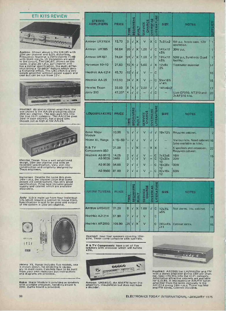
Amtron Shown above is the UK185 with 20W per channel and 0.5% distortion, Frequency response is 20Hz-20kHz _idB with three inputs. 15 transistors are used in the circuit. The UK187, shown on the cover, is also 20 r.m.s. per channel and has a similar specification, the main differ- ence being a 'Quadrik' feature which gives a 4 -channel effect. The UK110/A is a very simple amplifier without power supply and case but can be run from 12V.
Heathkit do several stereo amplifiers, the one shown is the AA -29 producing about 35W per channel. The spec puts this into the true Hi-Fi category. The AA1214 gives 15W in each channel, has a good spec though not as high as the AA -29.
Henelec Texan Now a well established design, 20W per channel and with an excellent specification. Very slim line construction and originally designed by Texas engineers.
Harverson Despite the name this gives 14W r.m.s. per channel (nice that some people are conservative). Has very good specification. Price here includes power supply and cabinet which are available separately.
Josty 310 is made up from four Individual kits which require a cabinet to house them. Specification is said to be good and output of the system is 10W per channel.
Helme XL Range includes five models, one is shown above. No soldering is necess- ary in most cases. Cabinets have to be built from your own resources but instructions and diagrams are provided.
Baker Major Module is provided as speakers with a simple crossover, handling power is 20W. Baffle board is provided.
STEREO AMPLIFIERS PRICE
web w(2- i-
C/3
cc
Z
m m
w
v¢ Q
cc z
ÿ U
N
L m
c):1
W cC
Q ¢ w
SIZE NOTES w j aa.
O co
Amtron UK110/A 12.73 3 X V X C 7x31/4x2 5W p.c. Needs case. 12V operation.
1
Amtron UK185 56.64 20 X 1.00 V C 141/4x10 20W p.c. 1
x314
Amtron UK187 74.64 24 X 1.00 C 18'/2x10 50W p.c, Synthetic Quad 1
x31/4 facility. Harverson 10+10 21.80 10 X V 5.00 V X 12x8x Testmeter essential 14
2%
Heathkit AA -1214 49.70 10 V V V - C 15
Heathkit AA -29 113.50 24 X V - C 5'/4x16% 15 x141/4
Henelec Texan 33.93 6 X V 2.00 V 14'Y2x6x2 17
Josty 310 47.23* 4 - V C - Uses GP310, NT310 and 20 2xAF310 kits.
LOUDSPEAKERS PRICE
W
H
fA
Z ?
W m
_J
3 m
w v CD
is WU o
rn
w CC
La i
W cc O
Q m w ~ -
SIZE NOTES w_
J a DD
co
Baker Major 10.95 Y2 V V V V V 19x1212 Requires cabinet. 2 Module
Helme XL Range c 15-50 - V V - Various kits. Need cabinets 16 (also available as kits).
R & TV 21.00 - V X - X X - 5 speakers and crossover. 22 Components 950 Requires cabinet. Heathkit AS -9515 14.05 2 V V V - C 7x12x6 15W 15
AS -9520 3460 2 V V V - C 12x20x 20W 10
AS -9530 54.00 2 V - C 16x26x 30W 12
AS -9560 81.00 2 V V V - C 32x16x 60W 12
AM/FM TUNERS PRICE
1
co) CC w 2
m
H
m
w w 0
Q
iiiU
co Q
ti< C: W
O
w CC O N
w
J
SIZE NOTES CC
w D.
3 q
Amtron UK540/C
Heathkit AJ1214
Heathkit AR2000
21.28
51.90
105.90
8
7
25 V
X
X
1.00
V
V
C
C
C
12x31/4 x5'%
24'/2x412 x11
Not stereo. Inc. cabinet.
Cabinet extra.
1
15
15
Heathkit have four speakers covering 15W - 60W. These come complete with cabinets.
R & TV Components have a set of five speakers with crossover which will handle 45W.
Amtron UK540/C. An AM/FM tuner (no amplifier). Inexpensive but does not have a decoder.
Heathkit AR2000 has LW/MW/SW and FM with a stereo amplifier giving 18W per chan- nel. Spec lifts this into the Hi-Fi category. Alternative attractive cabinets are available for £10.80. A less expensive AM/FM tuner - amplifier from the same company is the AR1214 giving 15W r.m.s. Tuner has MW and FM bands. Cabinet included.
36 ELECTRONICS TODAY INTERNATIONAL-JANUARY 1975

FM TUNERS PRICE
co tc
Z t=om coco
I-
W
uu ec
CCV
u)
9 ÿ w
iu tc
<
~_
SIZE NOTES Gt w
as
te
Heathkit AJ 29 124.20 18 V X V - C 514x16% 15 x14%2
Heathkit AJ1510 314.00 30 X X V - C 6x161/2x Inc. cabinet. Reviewed in 15 14% ETI Oct. 74.
Henelec Stereo FM 23.13 5 X 2.00 V 73/4x6x2 Reviewed ETI June 74. 17 Mk Ill
FM Varicap Stereo 28.50 2 I V V p 8%x2%x Reviewed ETI June 74. 10
Tuner 61/2
Josty HF325 28.44* 2 V J - V C - No cabinet. Part module. 20
Nelson Jones 32.21 7 X X V V 63%x151/2 Price Inc. Lowest cost 18 2% decoder.
Hart FM3 31.16 3 X 1.00 V V 41/2x1'%x Uses modules. Inc. Case. 13 10
integrex Low-cost 29.00 3 X V V 63/4x151/2 Inter -station mute. 18 Stereo Tuner x2%
..
MISCELLANEOUS RADIOS
PRICE
(-
tA cc
2 ? w m m
ill
(WjCC 5,.<
w v t/f
N
ÿ cc
> O
W
Q ¢ h J
SIZE NOTES W
á
cil
Sinclair Micromatic 2.68 1 V V V 13/4x11/2x Ultra miniature, earphone 23 '/: only.
Heathkit Tiger FM 10.20 5 X V C 11 x6Y2x 15 3%
Heathkit 4 -Band 33.50 8 X V C 5'/2x14'/2 15 SW717 x8
Heathkit 6 -Band 96.15 16 V X V C 61/2x111/2 15 GR78 x9
Amtron UK525/C 12.71 4 J X 1.00 C 6'/4x5'/4x 120-160MHz 1
2%2
Amtron UK 546 6.65 4 X 1.00 V C 3x4x1% 25-200MHz 1
AM/FM
Amtron UK515 7.92 4 V X 1.00 C 6x3x1'/2 MW Radio 1
Amtron UK500 29.01 15 X 1.00 V C 16x3'/4x AM/FM Receiver 1
5%
Josty HF75 3.95* 1 V V - C - 20
Coder 17.33 5 V X 2.00 11 x5x 5 Multiband -6 4%
Johnson's CV2 5.00 2 V 1.50 V V 4x4x2 80-180MHz 19 Globe King
HAC DX 4.50 2 X 1.50 V 6x6x4 S.W. tuner 12 One -Valve
HAC K Mark 2 8.50 2 X 1.50 V 6x6x4 S.W. tuner 12
Globe Patrol 15.49* 3 X V - C 5x9x4 4 Bands 24
Sinclair Micromatic. Perhaps the most common introduction to kit building. Has been around for years but remains a favour- ite. TRF, reflex, two transistor circuit using two mercury batteries.
H.A.C. have two kits, one using a valve but is a tried, tested design. Ideal beginners kits.
Josty The inexpensive HF75 will pickup high frequency transmission, either AM or FM including the aircraft bands.
Heathkit have two, very high spec FM tuners. The AJ29 is of fairly conventional design but the AJ1510 is an incredible unit with digital tuning and a fabulous number of facilities. The AJ29 is illustrated above.
Henelec Stereo FM Mk III uses slider pot to control the varicap tuning. 9 transistors, 9 diodes and decoder 1.c. are used. No test equipment is required. Can be modified to cover aircraft bands.
Hart produce an unusually shaped push- button tuner using prealigned modules. This is designed to be adjacent to record player plinth.
Electrospares FM varicap stereo tuner has five push -buttons and uses pre -aligned r.f. and 1.f. modules. Incorporates PLL decoder. Attractive cabinet included.
Josty HF325 uses prealigned tuner which can operate from 12-55V. designed to connect to their HF330 stereo decoder (£11.40).
Integrex produce two FM tuners, the Nelson -Jones which got a good review in June's ETI albeit a fairly complex kit. They have since brought out a simpler, slightly cheaper model which uses prealigned modules.
Amtron have a variety of receivers and tuners covering most bands, including some unusual features. Those interested are refer- red to their catalogue.
Codar The Multiband -6 comes from a company who normally produce ready - built receivers. It is a TRF covering 550kHz-30MHz. Uses four coils and modules. SSB facility. Loudspeaker not supplied. Uses PP6 battery.
Heathkit have a wide range of receivers ranging from portable sets such as the Tiger FM up to multiband receivers of professional quality. The SW717 covers 550kHz to 30 MHz with a large dial. The GR78 has addit- ional long wave and better bandspread. Runs off rechargeable batteries.
Johnson's market a triple purpose VHF kit covering 8 -180MHz, it can be used as a converter, tuner feeder or as a receiver with headphones.
Tandy Globe Patrol. A simple receiver covering 540kHz-30MHz. Built-in speaker and comes with 'where to listen' guide. Battery powered.
ELECTRONICS TODAY INERNATIONAL-JANUARY 1975 37

ETI KITS REVIEW
Heathkit have a push-button car radio kit in their range suitable for 12V +ve or-ve chassis models. Medium and long wave coverage.
R & TV Components produce the inexpen- sive Tourist in two models, the Mk I which is cheaper but requires quite a bit of work but the Mk II is suitable for beginners as no soldering is required! The company tell us that there are considerable delays at present on the Mk II.
Heathkit have two Induction balance metal locators in their range, the GD348 is shown. This has speaker output and a meter. The GD48 is an older model, still available, at a lower price.
Minikits market the Treasure Tracer Mk Ill with speaker output and using the BFO principle. This comes with a prebuilt search head.
Amtron produce the electronics section for a metal locator operating using the BFO principle. A handle is all that is required.
Heathkit have several calculators In their range the one Illustrated is the desktop !C2108 which is mains operated with large displays. Rechargeable models are also available.
Sinclair calculator kits are well known and ETI has given details in the past of both the Cambridge and Scientific (the Scientific kit is illustrated). At £19.95 this is by far the cheapest scientific calculator available.
CAR RADIOS PRICE w
1
z
m
b
m
V >= rw!) U
Ñ cc w
O
wrn
cc
a w
J SIZE NOTES J
ÿ
Heathkit CR9502
Tourist I
Tourist II
20.55
7.15
8.25
5
7
2
'1
X
V
X
X
X
V
2.50
2.50
X
X
C
d
V
7x6x2
7x4'/4x2
7x43/4x2
Push-button
Push-button
As Tourist I but no soldering. (long deliveries at present)
15
22
22
CO
w CC
METAL w w C7 Q Ñ Ix LOCATORS PRICE Z ta Q ÿ
& SIZE NOTES
w C7
J S ac rJ w Ñ
6. n.
CO m tw/) O J ÿ
Amtron UK 780 13.09 2 V X 1.00 0 Handle not included 1
Heathkit GD 348 48.60 J X V C - Induction Balance 15
Heathkit GD 48 37.80 V X V V - Induction Balance 15
Treasure Tracer 11.03 J V V VV - BFO 21 Mk III
CALCULATORS PRICE w P
CC
Z 2
m m
w
Ú j= U)
rA
/61)
cc wa O
w
CC
Q IX 111
J SIZE NOTES
_w
J o -
Ñ
Heathkit IC 2006
Heathkit IC 2108
Sinclair Cambridge
Sinclair Scientific
39.95
43.20
14.95
19.95
8
8
2
2
J V
V
V
X
X
V
V
V
V
2.50
2.50
V
V
C
C
ads
ads
7x2Y4x 9%
4'/zx2x%
4'/2x2x%
Other models available
Desk top model.
Details in Oct. 74 ETI.
15
15
23
23
BUILDING MODULES
PRICE
I-
o wMULTIPLE
w
Z
to m
w UM
U)
w
ÿ w
O
w cc
< CC
J
SIZE NOTES cc
w J o-
á)
Electroni-kit
Tandÿ
8.80 to 33.95
8.99 to 17.95*
-
- V
V
- -
- -
J
X
V
C
- -
Several versions
Several versions
9
24
Electroni-Kit have a wide range of building modules for the absolute beginner, the sim- plest of these will make up 16 projects whilst the largest enables 150 circuits to be built. There' are 'add-on' kits also available. Each comes with a very extensive manual describing each circuit.
Tandy stores market four starters modules which are a base -board with spring clips. All that is necessary is to connect hook-up wires to the points specified. The simplest makes up 20 circuits whilst the dearest has 100 ideas. These come complete with an educational manual.
38 ELECTRONICS TODAY INTERNATIONAL-JANUARY 1975

W
CC W CO) CC
CC
TEST GEAR PRICE 2 v á ÿ á SIZE NOTES W F-
w w .
Cross -Hatch 8.71 4 J J 1.77 J ./ 5%x3x3 Leads 54p extra 3 Generator
A.F. Signal 23.20 8 J X 1.00 J C 1
Generator UK437
Digital Frequency 91.80 15 J J V C 3%:x8"/4x 1Hz-100MHz, 5 -digit. 15 Meter I B-1101 9
Chart Recorder 100.45 20 J J V C 15x6x9'/4 Paper rolls £2.20 each 15 I R -18M
5MHz General 84.25 12 J V V C 123/4x9'/4 Scope 10-102 x16% 15
The Amtron and Heathkit catalogues both contain an extensive range of test equipment. Readers interested primarily in test equipment are referred to these. Both these catalogues and the one from Josty contain details of numerous power supplies.
DIGITAL CLOCKS PRICE W
com
CC
Z Jw
W
> á
ÿ
N
O
W
W
J
SIZE NOTES
® ct
a tDn
Digitronic II
Heathkit GC 1005
Amtron UK820GB
32.12
34.55
36.24
2
6
15
J
J
J
- X
50p
V
£1
J J
C
C
5'/4x4Y4x 2%
7x2'%43/ Alarm clock.
Shows seconds.
4
15
1
ELECTRONIC IGNITION PRICE
W
1-
z Z C7
m
i-
m
V¢ rJ < [t V v
y W N x W
Ó
Q' cca H J
...... ....._-. NOTES
ct W
a
Amtron UK875 14.47 3 J X 1.00 J C 4x23/4x -ve earth. 1
2%
Bi -Pre -Pak 6.73 6 X X 1.87 V J 5%x4x3 ETI Design, +, -ve earth. 3
Debar Scorpio 12.72 4 J 2.16 V V 7'/4x43/4x 6/12V, +, -ve earth. 7 2%
Electrospares 11.50 4 J J V J J 4%x31/2x 6/12V, +, -ve earth. 10 Scorpio 2%
Heathkit CP 1060 25.95 2 J X V - C 3'/4x33/4x -ve earth. 15 6
Sparkrite Mk2 10.93 2 J 2.20 J V 6x4x3 +, -ve earth. 8
Tandy 28.95* 3 J X 2,50 X C 5%x3x3% -ve, earth. 24
ELECTRONICS TODAY INTERNATIONAL-JANUARY 1975
Bi -Pre -Pak sell a Cross -Hatch generator which enables a colour TV set to be pro- perly converged. This is cheap enough to fit permanently into the back of your TV.
Amtron's UK437 shown on the cover and is an A.F. Signal generator covering 15Hz- 22kHz in three ranges. It has distortion of 1% and a maximum output of 2V. Amtron's range in the test gear field is extensive and reference should be made to their catalogue.
Heathkit have a very wide range of test gear in their catalogue. We show their 10-103 Scope and the I R -18M chart recorder on the cover. The range in the test gear is huge - several oscilloscopes and digital frequency meters`for a start. This varies in cost from true professional to amateur market.
1'ilLíïlJll -
I _I '-l'= 1_I:1
II:II1i157EI'II
Bywood's Digitronic II is a kit available In various versions from a company who spec- ialise in digital clocks. A recent ETI offer on these proved very popular. The Digitronlc li Is shown on the cover.
Heathkit's GC1005 is one of the company's most popular products and Is featured on the cover their catalogue. It has an alarm fac- ility, Another model - the GC1092A at £50.80 is now available with a variety of extra features Including reserve battery operation.
Amtron also have a digital clock In their range which uses 15 TTL i.c.s.
Bi-Pre-Pak's electronic ignition Is based on the ETI design of September 1973. This is suitable for positive or negative chassis operation and incorporates a burglar foiling devices.
39

ETI KITS REVIEW
Forgestone have the only DIY colour TV kit on the market; this is available with several screen sizes. Details were given in November 1974 ETI.
Heathkit market a 12in. B & W TV for the U.K. UHF bands which can be mains or 12V battery operated.
E.D.A.'s Fluorescent light is a simple unit which runs from a 12V battery and pro- duces 8W.
Cosmic's Nova Light Display is a slim unit which needs no direct connection to the sound source; a mike is used.
Teleradio's Microtol Radio control equip- ment is sophisticated and controls up to five functions.
Tandy market a pair of stereo headphones In kit form which incorporate a volume control for each ear. 8-24 ohms.
Tandy's Lie Detector relies on changes in skin resistance under tension which alters an audio tone.
Amtron's Noise Reduction unit alters the pass -band dependent on input level thus being more effective than a scratch control.
Amtron's Guitar Preamplifier has low output impedance and is suitable for most guitar magnetic pickups. Gives 32dB gain.
Aerial Preamplifiers are available from Josty and Amtron. Details of frequency coverage and gain are in the catalogues.
AO
Amtron market a number of burglar alarm units which use a variety of trigger systems. The UK790, a capacitive type, switches when a body comes near it.
Heathkit's Informer Ultrasonic Intrusion Alarm is built into book form. It has a
built-in 30 sec delay. A suitable alarm bell is available for £7.55.
Light Dimmers covering 200W to 2.2kW are sold by Josty and Amtron.
. .. .. .. .. ..... .,
. s
:
.
PRICE
fn cc
Z
00
J> m
0 Ix
v
Ñ
N a ¢ O
W
cc
W
J
SIZE
. .:--
`
NOTES Ir W
Forgestone 400
Heathkit GR9900
About £200
68.00
70
12
X
J
X
X
V
V
J J
C
Depends c.r.t.
161/2x101/2240V/12V x9
Price depends on screen size. Colour.
B & W.
11
15
MISCELLANEOUS PRICE ,i,
F"F:m
rs CC
z O
m
F-
J
ill
-Q V= W
°U vi
fi)
CCCC W
O
W CC Z
fW ..
J
SIZE NOTES J a CO
Fluorescent Light 3,19 % J J 85p J 12x1'/2 Diffuser 59p each. 8 x2
Nova Lighting 26.34 3 J J V J 24x12 6 Display x1%
Microtrol Radio 88.60 X J V J J - Complete system. 25 Control
Stereo Headphones 13.49* 3 J X V X C - 24
Noise Reduction 8.76 4 J X 1.00 C 4x3x1'/2 1
Unit UK127
Lie Detector 7.95* 3 J X V X C - 24
Guitar Preamplifier 5.62 2 J X 1.00 J C 4x3x1'/2 1
UK835
AM/FM Aerial 3.59 2 J X 1.00 J C 3x2x13/4 VHF/UHF (ÚK285) 1
Preamp UK230
Aerial Preamp 6.51* 2 J X - J C - 20 HF380
Capacitive Burglar 8.94 3 J X 1.00 J C 4x3x11/' 1
Alarm UK790
Ultrasonic Alarm 26.08 20 J X 1.00 J C 6%x2x 1
UK815 5%
Heathkit Informer 28.10 12 J X V C 21/2x10% Ultrasonic 15 G D-39 x7%
200W Light 8.84 2 J X 1.00 J C 3x2'/2x 1
Dimmer UK640 1%2
400W Light 5.60* 2 J X - J C - 2.2kW version available. 20 Dimmer AT56
Psychedelic Light 17.85* 2 X - J C - 20 Control AT65
Digital Thermo- meter ID -1390E
38.90 12 J X V C 2%x7x5 15
Stereo 21 20.55 4 J X £2.50 X X - No soldering. 22
Josty's Psychedelic Light Control 400W in each of three frequency channels. Lights, case etc. are not included.
R & TV Components have a very inex- pensive stereo system which gives a very decent sound if not Hi-Fi. Glue is all that is required.
Heathkit's Digital Thermometer has the appearance of a digital clock and gives either Fahrenheit or Centigrade readings in the range -300 to +50°C. Monitors both inside and outside temperature.
TELERADIO ELECTRONICS
If you require further data on radio control systems or quality amplifier kits send s.a.e. to
325-7 Fore Street, Edmonton,
London N9 OPE.
40 ELECTRONICS TODAY INTERNATIONAL-JANUARY 1975

1. Amtron (U.K.) Ltd., 4-7 Castle Street, Hastings, Sussex.
2. Baker Loudspeaker Co. Bensham Manor Passage, Thornton Heath, Surrey.
3. Bi -Pre -Pak Ltd., 222-224 West Road, Westcl iff-on-Sea, Essex.
4. Bywood Electronics, 181 Ebberns Road, Hemel Hempstead, Herts.
5. Codar, Valcon Works, Burrell Buildings, Churchill Industrial Estate, Lancing, Sussex.
Cosmic Electronics, 62 Ongar Road, Brentwood, Essex.
7. Dabar, 98 Lichfield Street, Walsall, Staffs, WS1 1 UZ.
8. Electronic Design Associates, 82 Bath Street, Walsall, Staffs, WS1 3DE.
9 Electroni-Kit, 498 St. John's Street, London E.C.1.
10. Electrospares, 288 Ecclesall Road, Sheffield.
11. Forgestone Colour Developments Ltd, Ketteringham, Wymondham, Norfolk.
12. H.A.C. Shortwave Products, P.O. Box 16, East Grinstead, Sussex, R H19 3SN.
13. Hart Electronics, Penylan Mill, Oswestry, Salop.
14. Harverson Surplus Co. Ltd., 170 High Street, Merton, London S.W.19.
15. Heath (Gloucester) Ltd., Gloucester GL2 6EE.
16. Helme Audio Products Ltd, Summerbridge, Harrogate, Yorks.
17. Henry's Radio Ltd., 303 Edgware Road, London W2 1BW.
18. lntegrex Ltd., P.O. Box 45, Derby, DE1 1TW.
19. Johnson's Radio, - Shaw Street, Worcester, WR 1 3QQ.
20. Josty Kit (U.K.) Ltd., P.O. Box 68, Middlesbrough, Cleveland, TS1 5DQ.
21. Minikits Electronics, 35d Langley Drive, London El1 2LN.
22. Radio & TV Components (Acton) Ltd. 21 High Street, Acton, London W3 6NG.
23. Sinclair Radionics, St. Ives, Hunts.
24. Tandy Corporation, Bilston Road, Wednesbury, Staffs., WS10 7JN.
25. Teleradio, 325 Fore Street, London N.9.
ELECTRONICS TODAY INTERNATIONAL -JANUARY 1975 41
The
FORGESTONE 400 a high quality colour television receiver.
A complete and up-to-the-minute Electronic Kit*
with all these plus features ... 9 integrated circuits Ready -built and aligned IF module High quality components Plugs and sockets for easy panel removal Full technical construction manual
less cabinet, which can be manufactured yourself from normal DIY sources.
Send for further details of the Forgestone 400.. .
the quality kit for the constructor of today.
Thick film resistor units Glass epoxy printed circuit panels Fully isolated power supply Each module kit available separately LT supply regulator
Forgestone Components FORGESTONE COLOUR DEVELOPMENTS LIMITED
Ketteringham, Wymondham, Norfolk Telephone: Norwich 810453 (STD 0603)
ELECTRONIC IGNITION
SCORPIO Mk II Capacitor discharge ignition system
(Reviewed 'Safer Motoring' May 1974)
AVAILABLE IN 6V. or 12V. VERSIONS
Promotes easier starting - even under sub -zero conditions. Improves acceleration, gives better high speed perform- ance and quicker engine warm up.
Eliminates excessive contact breaker burning and pitting. Promotes Fuel Economy.
DON'T TAKE OUR WORD FOR IT! Send s.a.e. for copy of 'Safer Motoring's' independent test
report, together with further details and prices.
Available in kit form . £11 78 (Construction manual available separately at 25p)
Built and tested unit, ready for fitting to your vehicle £14.49
PLEASE ADD V.A.T. TO ALL ORDERS AND STATE WHETHER 6V. or 12V. UNITS REQUIRED,
DABAR ELECTRONIC PRODUCTS r- 98, Lichfield Street,
Walsall, Staffs. WS1 1 UZ. 22:12=7.
AMTRON PRICES
ARE GOING DOWN!
JUST LOOK AT THESE PRICE REMOTIONS'
UK 187 HI-FI QUADRIK STEREO AMPLIFIER 20+20W. OLD PRICE £110.45NOW£72 23
OL390 VOX D PRICE £14.98 NOW £11.17
UK 460/S PM SIGNAL GENERATOR OLD PRICE £19.96 Now£15.95 UK 500 LW/MW/FM RECEIVER OLD PRICE £43.60 NOW£3133
* UK 540/C LW/MW/FM TUNER OLD PRICE £3 NOW£2103
* UK 560/S TRANSISTOR ANALYSER OLD PRICE £3_ NOW£24+01
Send
1 0 pfor a
'brochure
g mTR o> iTK
PRICES INCLUDE VAT.
4 & 7 CASTLE ST., HASTINGS SUSSEX TN34 3DY
TEL (0424) 437875.
42 ELECTRONICS TODAY INTERNATIONAL-JANUARY 1975
PAST SERVICE.
EIEfTf11Q5 TQ T!ifI1t1IIi WIND OR BE KS.Dl SEND C.W.O. ADD VAT TO ALL PRICES IN U.K. P&P 15P, EUROPE 25P.OVERSEAS 65P.
MONEY BACK IF NOT SATISFIED. LARGE STOCKS, LOW PRICES. ALL BRAND NEW TOP GRADE FULL SPEC DEVICES.CALLEAS WELCOME,
CATALOGUE/LIST FREE SEND S.A.E.
Digital Displays MINITRON 3015F 3-90? £1.15 ea
LED 0.3" digit 0-900 £1.49 ea
50Mß0 LED 0.6" 0-9EP £2.25 ea
LIQUID CRYSTAL 6 digit £18
7:5 SOURCE OR RED DIFFUSE LEC5.:so STYLE.NO CLIP. 14P ea
7-7'4 RED LED & CLIP 17P ea
-G ," RED LED & CLIP 18P ea
RANGE & CREEN LEUS: MINI 25P ea.BIG & CLIP 3314 ea
INFRA RED LED £1.255777 33P. PS12 PHOTO IC/amp/switch £1.
OiCFTfiL CLOCK MOS INTEGRATED CIRCUITS. AY51224 4 DIGIT CLOCK supplied with 14pin socket & data £4.25
MM5311/14 6 DIGIT CLOCK with 28 pin socket & data £7.50
31DIGIT DVM AY53500 £7.50 4DIGIT COUNTER/DRIVER £7.50
702 OPA 69p 703 RF/IF 28p 709 T099 21p 709 DIL 14 29p 710 DIL 14 .36p
720 Radio £1.39 723 Regulator67p 741 TO99 29p 741 DIL8 31p 741 DIL14 31p 747 Dual 741 89p 748 DIL 8 36p
1505 IC A/D Converter £7
7805 1A5V £1.59 7808 1A8V £1.69 7812 1Al2V £1.69 7815 1A15V £1.69 76009 ¡is' AF 75p 76013 6W ÁF£1.39 8038 Sig Gen £3
CA3046 69p LM301 OPA 49p Lí4307 OPA 49p LM308 11iBoPa 95p L4309K Reg.£2.29 LM371 í2F/IF £2
LM3725 AF/IF £2
LM373 £3
LM377 2x211 £2.69 LM380 2W'AF 99p L14381)2xpre,£2 LM382)amp £2
LM3900 4x0PA 69p
NC1303 £1.20 MC1306 49p ;.IC1310 & LED £2.69
CASSETTE, pp_ j^^-JJ//
MC1312 SQamp £2.50
mechanics 2 L LS ° O DIG133G 6£1 9p
STEREO CASSETTE MECHANISM.
As used in imported types costing £100.Only requires a case & electronics.Heads supplied.Send far data 15p..
7101350 55p MC1351 71p 1áC1352 71p í1C1357 £1 MC1358 £1 IC1375 £1.?.5
a SQrOcOO rndaeO[ra MFC4000 áW AF 35p MFC4060 54p MFC6030 52p MFC6040 90p MFC8010 £1.10 MFC8040 £1
NE531 35V/us £2
NE536 FET OPA£2 5E540 Driver £1
NE546 AM Rx£1.50 NE550 2v ref 79p
NE555 TIMER 67p
NES56 Dual"£1.30 NE560 PLL £3.15 NE561 PLL £3.15 N'E562 PLL £3.19 NE565 PLL £2.69 5E566 Gen £2.49. NE567 code £2.69 SN72709 709 29p SN72741 741 31p SN72748 748 36p SN76131 £1.20 5576660 Fh1IF £1
8576611 IF £1.25 TAD loo & IF £2
25400E £3 ZN402T £.1.75 ZN403 Servoi2.50
ZN414 AM Rx£1.09
7400 etc gates 16p 7413 Schmitt 31p 7447 driver £1.09 7470/72 32p 7473/74/76 39p 7475 48p 7490 Counter 63p 7492 Counter 69p 74121 mono 45p 74141 driver 83p
Full range in Cat..
SPECIAL OFFERS
741 29p MFC4000 35p 555 67p 25414 £1.09
BC107,BC108,BC109 9p ea 253055 39p Three for £1 115W/T03 or 90W plastic 253819E 16p 253053 17p ßF750/51/52/53 all 18p
1ASOVrect 4p ea I`1914 4p
Price each:- AC127/128 16p AC187/188 19p AD161/162 35p BC107/8/9 9p ßC132/4/7 18p ßC147/8/9 10p BC157/8/9 12p ßC167/8/9 12p ßC177/8/9 18p ßC182/3/4*11p BC212/3/4*12p *A or L
BCY70/1/2 15p BD131/2 39p 8EY50/1/2 1Sp BFY53 17p BSX20 12p MJE2955 95p MJE3055 62p MPU131put 49p CA91 8p
TIP29A 48p TIP30A 57p TIP31A 61p TIP32A 73p TIP41A 78p TIP42A 89p
TIP2955 90p TIP3055 55p TI543 UJT'25p I54001 4p I54004 6p I54148/914 4p 25697 13p 25706/8 10p 252646 49p 252904/S 20p 252926royg 9P 253053 l7p 253055 39p 253614 49p 253702/3 9p
253704/5 lOp
253706/7 9p
2::3708/9 Sp
253710/11 9p
253163/64 16p 253566/67 16p 253638 16p
253641/2 16p 253819E 16p 253832E 17p 253904/6 14p 254249 16p
BZY88 400mW ZENERS 9p
BRIDGE RECT IA SOV 20p
GAS SENSOR £2
GAS " KIT £S
TAG 1/400 55P C10781 SCR 4A/400V 55p
SC146D TRIÁC 10A 400V 75p
vero WEw IoW P,PICffi VERO. PINSx36 25p.
COPPER CLAD VEROBOARD 0.1" 21xS" 27p.21x3;" 24p.3.1x32"27p. 3;x5" 29p.3x17" £1.50 DIL IC's BOARDS 6x41" £1.50 24 way edge connector 60p
36way 90p. PLAIN 3',"x17 £1
FACE CUTTER 43p. FEC ETCIIANT
(lu
PRINTED CIRCUIT BOARD KIT £1.69 COPPER BOARD 6x4" 40p. DESOLDER BRAID reel 59p
HEATSINKS Sf/TOS & 18£/1'018 5p ea.
TV4 12p.TV3/T03 16p.4YI/T03 29p.
CAPACITORS 22pí to 0,1uf 4p ea.ELECTROLYTIC 25V 2/10/50/100uf 6p.1000uf 20p PRESETS VERT:Sp.RESISTORS5% 11p
POTS AB orEGIN ROTARY:12p.SWITCH 13p.DUAL 38p.
SLIDERS:SINGLE 26p.DOUBLE 48p.
SWITCHES:SPST 18p.DPDT 25p. MINI a":SPST 39p.PUSH 39p.
BENCH POWER SUPPLY 3-12V £5.
DIN PLUGS all 13p ea.Sockets 9p
TRANSFORMERS lA 6/12V £1.34 BHA 0002 MODULE 15R'.ATT AMP £5 EA1000 4W AF MODULE £2.49 8W/12V FLUORESCENT LIGHT £3.
Obi Sock ets PROFESSIONAL COLD PLATED & GREY NYLON. 8,14 or 16 PIN ONLY 15p each.
MHI CLOCK NITS MHI kits are a mid -way approach to building digital clocks, mid -way that is between a complete kit and
basic chips. The MHI kit contains clock chip, socket,
CA3082 degment friver, and a fibreglass PCB. The
outputs from the PCB are suitable for driving common anode LEDs such as the DL747 and DL707, most
manufacturers versions of these displays can also be
used. Other outputs from the PCB are for switches and any alarm facilities that the chip might have, thus
we have a clock module in exactly the same way as you might buy an audio amp module,
The MHI clock kit is partnered by the MHI display kit, a set of four or six LED displays plus a PCB. This
PCB interfaces directly to the clock PCB. The four main units (clock PCB, display PCB, switch matrix, transformer) may be mounted up to .15" apart from each other for use where there is not room for the whole unit behind the display board.
The additional components required to complete the
unit are standard components available through most
component outlets.
CLOCK KITS - DISPLAY KITS - MHI-5314/S £ 9.40 MHI-D707/4 MHI-5025/S £11.35 MHI-D707/6 Í51H1.7001/S £12.50 MHI-D747/4
MHI -D747/6
All prices on this advert exclude VAT.
£ 7.60 £11.00 £ 10.25 £15.15
DIGITAL CLOCK CHIPS
CLOCK CHIPS: MM5314 Basic 12/24Hr, 6 digit, 50/60Hz chip. £ 7.20*
7 seg outpúts. Very popular, simple
chip.
MM5311 As MM5314 but with additional BCD £ 9,00
outputs,
MK50250 6 digit alarm chip with alarm tone out- £ 7,60*
put, Standard basic alarm facilities.
CT7001 Time, Date & Alarm on one 6 digit £ 9.80*
chip. The Alarm can be used in 3 modes including a time switch. Clock -Radio & Snooze features. 7 seg outputs, 50/60Hz or 100.8kHz input frequency.
CT7002 As CT7001 but with BCD outputs not £ 9.80
7 seg.
TMS3952 Stopwatch chip, most regd. stopwatch £10.50
functions 6 digits (hhmmss or mmssss), 300kHz input. 7 seg output. Special price.
HEEC2 8 digit (HhMmSsss), stop/start/reset, £ 8.50
50Hz/60Hz/100kHz input, BCD output hard -wired alarm with repeat (snooze).
Can also be used as 8 digit decade counter.
CT6002 CMOS chip for Liquid -crystal displays, £19.54
12Hr, 1Hz colon, input 32768Hz or 65536Hz. Runs on 1.5V hearing aid battery for a year.
MM5316 4 digit non-mplxd alarm chip, will £15.00
direct drive 1-c or phosphor -diode displays.
* Available in a Mhll kit.
INWOOD BY WOOD ELECTRONICS,
181 Ebberns Road, Hemel Hempstead, Herts. HP3 9RD. Tel: 0442-62757
ELECTRONICS TODAY INETRNATIONAL-JANUARY 1975 43

Yamaha's CA -800 switchable class A/class B amplifier reviewed.
A SMALL but vocal number of hi-fi enthusiasts insist that for truly distortion -free amplification, nothing but Class A operation will suffice.
Even the best of Class B amplifiers, they insist, is an electronic abomination.
Until now this argument has been
difficult to evaluate. Whilst some Class
A amplifiers are audibly better than their Class B counterparts, the difference may well be due to things
other than the operating mode of the output stages!
Now, Yamaha have produced a
high-class amplifier with an output stage that can be switched to either Class A or Class B operation.
The amplifier, Yamaha's CA -800 - has a number of other unusual features as well. Like Leak's old Varisiope units, the CA -800 features variable -slope cut-off frequencies for bass and treble filters. It also has a
Most power amplifiers have output stages that operate in what is
usually called 'Class B'. In this mode of operation, two power transistors are connected so that
as one'pushes' the other 'pulls'. A positive going signal, for example, will cause one transistor to
conduct and the other to turn off. Class B is an efficient mode of operation and quite high power outputs
can be achieved econmically, but so-called 'cross -over' distortion will be
generated unless the circuit is very carefully designed. Despite this 'disadvantage', several modern Class B operation amplifiers
have very low distortion indeed. Class A amplifiers have an output stage arranged so that, with normal
input levels, the output transistors are never driven into either cut-off or saturation.
In theory, the output waveform is identical to the input waveform. Distortion is very low indeed but the output stage's efficiency is very
low. Because of this it is not practicable to build high power output Class A amplifiers.
variable loudness control that operates independently of the main volume control.
A very wide range of facilities is
provided. There is a bass attenuator with a cut-off frequency selectable at
either 500 Hz or 250 Hz - together with a central 'defeat' position; a
treble filter with cut-off frequencies of 2.5 kHz and 5 kHz; a low frequency filter (70 Hz and 20 Hz) and a high frequency filter (12 kHz and 6 kHz).
Also provided is a switch for selecting Class A or Class B operation, and the aforementioned loudness control which provides a set of contours for true compensation for the physiological response of the ear.
The rear panel of the amplifier has all
necessary inputs together with a
preamplifier out and main amplifier input sockets with an electrical coupler switch; two microphone sockets; and a switch for selecting impedances of 100 k2, 50 k2, or 30 k2 on phono 1 input.
With one or two minor exceptions, the amplifier is constructed to truly professional standards. For example, each of the audio sockets on the rear panel, with the exception of the speaker outputs, is terminated on a
printed circuit card which is itself connected to the preamplifier cards via gold-plated plug-in sockets. The
44 ELECTRONICS TODAY INTERNATIONAL-JANUARY 1975

SUMMARY: The Yamaha CA800 amplifier offers a
performance which is generally better than most other amplifiers regardless of price. It is designed for the purist who is seeking the ultimate, but that the ultimate is "CLASS A" output operation is something that has yet to be proven!
preamplifier cards themselves are fully shielded from the rest of the unit by well designed steel covers to reduce magnetic and electrostatic induction. The function selectors extend through from the front panel to switches which are incorporated within this shielded cover. All of the circuitry mounted behind the front panel is also shielded in either individual sub -shields or partial shields around individual switches and terminations.
In keeping with the latest technique in amplifier layout, the main amplifier cards and their associated heat sinks are constructed as complete modules with direct connection between the printed circuits and the power transistors.
It was interesting to note that the leads running close to the heat sinks are individually protected with glass insulation spaghetti to preclude the possibility of melting or shorting wires. The printed circuit cards are all individually coated on the rear faces to prevent corrosion, electrolysis and fungus, problems which plagued many earlier and cheaper pieces of Japanese equipment.
One of the few details that precludes this amplifier from being a fully professional unit is the use of phenolic resin based cards in lieu of the more often used epoxy glass cards found in true professional equipment.
The amplifier design incorporates a number of highly desirable features including a relay operated protection circuit to switch off speakers in the event of a substantial dc level appearing at the speaker terminals. There is also a fully -electronic protection circuit to protect the output amplifier and its silicon power transistors against short-circuiting or unusually low speaker load impedances. In addition, each output amplifier card incorporates two fast acting fuses to provide a third stage of protection.
The amplifier is constructed on a
strong steel chassis within a very well made and adequately ventilated veneered plywood cabinet. The unit is readily capable of being rack mounted should this be desired although its frontal dimensions are 50 mm short of the standard 482 mm (19") rack mounting.
Power Output (at 1kHz) CLASS B CLASS A
Frequency Response at rated output at
1W 10woutput output
" at Channel Separation at Rated Output Hum & Noise re Rated Power
Volume control at maximum gain Volume control at minimum gain
Input Sensitivity for Rated Output Aux. 1 Aux. 2 Tuner Phono 1 Phono 2 Main Amp. 400mV
-87dB (A) -87dB (A) CLASS B 100mV 100mV 100mV 2,8m V 2.8V 900mV
Total Harmonic Distortion (at 60W output and 12.5W output respectively with both channels driven) C ASSB (60W + 60W) C ASS A (12.5W + 12,5W) 100Hz 01% Ç 01º/ 1kHz .01% W.01% 6.3kHz 0.45% 0.02%
intermoduiation Distortion less than 0.05% Tone Controls Filters
250Hz + 15dB - 13dB
5kHz Treble 10kHz + 6.5dB - 7.5dB
Bass 50Hz
HOW IT PERFORMED Evaluating the electrical performance
proved to be particularly interesting, for excellent though Yamaha's claimed specifications are - the unit is in most respects even better!
In the Class B mode for example, the amplifier is capable of producing a
true 60 watts into both channels at 8(2 impedance with a distortion level lower than the manufacturer claims for 50 watts. Likewise, the performance at 12.5 watts in the Class A mode is better than Yamaha's claim for 10 watts (both channels driven into 8(Z).
It is of course the matter of distortion, its measurement, and its subjective evaluation, which makes this amplifier different from all others, for Yamaha have provided the facility for being able to select Class A or Class B operation at the flick of a switch. Amplifiers, whether Class A or Class
B generally produce more distortion at low power levels than at levels closer to their maximum power output.
A 60 watt Class B amplifier for example may generate four or five
times as much distortion at five watts output than at 50 watts output.
Class A amplifiers have similar characteristics, but to a lesser extent - so that a 10 watt unit (quite large for Class A operation) will be working closer to its lowest distortion point at the same five watt level. At least that's what all the text
books say - but to some extent Yamaha appear to have hoisted themselves by their own petard, because the CA -800 working in Class B produces so little distortion anyway that further reduction by switching to Class A seems to be of only academic interest. Certainly it can be measured, but after many hours of very careful listening at all sound levels we could not hear any difference.
Yamaha claim that the very low level of residual distortion at low listening levels (in Class B) can be heard. It could well be, but it must be by perfectionists whose hearing is a great deal more sensitive than ours!
Continued on next page.
YAMAHA CA800 STEREO AMPLIFIER 60W (rms) into 8¿ both channels driven
12.5W (rms) into 8$Z both channels driven 20Hz to 20kHz ±1dB 20Hz to 20kHz±1dB 20Hz to 20kHz ±1dB 100Hz -37.5dE 1kHz-38.0dB -70dB (Lin.) -68dB (Lin.) CLASS A 50mV 50mV 50mV
500Hz + 17dB - 14dB
2.5kHz + 10.5dB - 10.0dB
Loudness Control (at constant volume control setting) Loudness control at 10 50Hz + 13dB
10kHz +5.5dB Dimensions 436mm x 144mm x 323rnm Weight 13.5kg Price £210.25
ELECTRONICS TODAY INTERNATIONAL-JANUARY 1975 45

MEASURED PERFORMANCE
The measurable distortion of the amplifier is as low as any we have ever measured. In fact it presented us with a number of interesting problems in electrical measurement to be certain that our measurements were of amplifier distortion itself rather than distortion from our test oscillator.
The distortion products at maximum output were generally in the range -67 dB to -80 dB, re 0 dB at maximum output in the Class B mode, and in the range -74 dB to -80 dB re 0 dB at maximum output in the Class A mode.
Before embarking upon subjective tests we doubted our ability to be able to discriminate between distortion products 60 dB down on the funda- mental component (less than 0.1%). After completing our tests we are convinced that we cannot hear such low distortion.
Is then the facility to switch to Class A operation a necessary or desirable feature - or is it just a gimmick?
Certainly its inclusion enables purists to decide for themselves whether or not Class A operation is worthwhile. A further advantage is that if you can still detect some distortion when switched to Class A, then you can be virtually certain that it's not coming from the amplifier! But our frank opinion is that for most people, the facility is an interesting gimmick. But, had Yamaha not incorporated such a
superb Class B output stage, it would have been a different matter - as we said they've hoisted themselves by their own petard!
One very worthwhile and technically valid feature is the inclusion of a
loudness control which is meant to be used as the preferred means of adjusting listening level. Whilst not unique to Yamaha, this feature is very desirable. Loudness controls are based on the psycho -acoustic fact that as
sound levels decrease, high and low frequency components are heard at subjectively lower levels than mid -range sounds. Eventually, at very low sound levels, bass appears to drop out altogether.
Many amplifiers have 'loudness' controls that compensate for this phenomenon to some extent. Yamaha's method, used in the CA -800, is far more complex. The subjective effect is that the overall sound at all levels has the same apparent frequency response as at the higher levels.
The control is used by firstly setting the loudness knob to a 'flat' position. Then the volume control is set to the loudest- volume that would normally be used. From then on, volume is
adjusted solely with the loudness
' Eswei 6 Igoe(
CrowAtep.^..
7z_ñüérç RyyEgBMIFAOHNgS
CA 800 AMPI IFIER__ AT 60, 10 _
1 WATT
RÑSPECLI V
HS_AiEi.S- OR IyH__
N__ p 2/877 S gn.., KAZ
t &us, 6 Ki.r
Polenliomeler Ranga. Jf.Q _ d8 Red, ,er ROS
Bruel 6 Ktqx Batel L xl;l;
Lower Llm freq.: _20 Hf Wr Speed 315 mMeec. PaPr
Q'25
1Bfdo
ElY_
.-_
'- . e
-
. T _ ..
I .
i I .l .
. 4 l
'
,e a+
..__ . _j.. 1
..
.
-r--.-3-1 ; .
;
f 3
. ... ..
3 .. . .
t ^ - _ 4d-2
. ¡
f
i f
i !' -f
i ! i i i ...
- - -. i--.4
I!
i .
20R10
101-5
...--
'
(
-
I j..
I
l t (, I î . :
_-- -_- -_ -_ ___
I ! _...--_-------- ` OL i
. . .---í -
20 10 Ha 50 100 200
OP 1124 Mullip y Frequency Scate b
Bruin 6 Klcer
Brun( á KICK( Polem.emeter Range'. 6Q_ d8 8.01,1,er 5(t-2
ewe^
..eaipr d8í41
4 2
F VEtL:`[CYbi ..
RESPONSfF YAMAHA_ CA -900 AMPLIFIER.-
.
SHOWING_ _.
EFFECT .OF..LOW CUT FILTER 2rrtt SET AT 20HZ .
and 70NZ 0240 HIGH SOT
FILTER SEL - AT 6KHZ and 10.5 FrrHZ.
I 1
500 1(00 2000
Zero Level
Brunl 6 Kle,
MS Lowe, Lem Freq 20 f ii ¡ ?,.
5000 10000 2
B,uel 6 Kt¢r
Ho Wr Speed i15 mm/sec P,p, Speed a_,.,,,, e a.ir.ao- e f f
oare 2t13.2.4 .
S,gn . KAZ 10 20 Hr b0
OP 1124 Mullipl, Frequency S,ate by
fl Bruti 6 Ktær
Brunt & Ape, Pnlen,ometer Range 50 50r22,
=wrr 48 d
ao-2
Med,w wg Obi FRFOUFNCV
RESPONSE .OF YAMAtIA. MDOF,t.16 5A-800 AMPLIFIER
EFFECT Of LOVONESS 2 l0 .CO"IT&AI. SWI C#i6T-.
vOLúri '
Re< No _ Oal,. 21912.4 S.gn ,.KAZ 0
10 20 H, 50
OP 1124 Muu.ply Fr quency $-ale by
T
100 5U I tIn, 2000 0000 10000 20000 10000 0 A B.0 L.
Zero Levn! 0612/21121 A B C L,n.
Bruet 6 KIceI
de RecIdlpr Rh}S tower L,m F,eq
Bru8 A tKer
20 H, Wr. speed .. !t, 010,,0 Pape, Speed 3 f . i. f ;.. g
I I
f_.fe _ .i_e }__.-..f
100 20 '10 ICOn 2004
t
2
a
8.48
8 60
6.45
.lt,
2 15
0 0
_-.-. ... 20000 40000 0 A 8 C Li
'612+21121 A B C L,n.
control - not with the main volume potentiometer.
As there are some hi-fi purists to whom loudness compensation is
anathema, the volume control may be used normally - with loudness compensation switched out.
The tone controls and associated switch are well designed and the use of two "break" frequencies follows a
growing trend. The choice of frequencies and the resultant response curves are not as different as might be expected, and a lower "break" frequency than 250 Hz and a higher break frequency than 5000 Hz may
well have been advantageous. One fault became apparent during
testing. With the amplifier set to maximum treble boost, and with the volume control set to maximum gain for response curve testing, we found it possible to introduce very high frequency (above audibility) instability in the output circuitry, and the amplifier could be induced into oscillation. This worried us, but it may well be that this was an isolated fault in this unit. In every other respect, however, the features of the amplifier were exemplary and it offered a
superb performance.
46 ELECTRONICS TODAY INTERNATIONAL-JANUARY 1975

Before you build a Heathkit send away for a free
bookful of encouragement. The new Heathkit catalogue. In it you'll find the whole range of Heathkit
electronic kits. The world's largest range, in fact. Every one of which you can build yourself.
Easily. And quickly. And, if you're not convinced, we're sure a quick
glance through our catalogue will soon encourage you to try.
You'll probably surprise yourself Because, even if you've never used a soldering
iron in your life, you can build a Heathkit. '
The easy to understand assembly manual and Kit Builder's Guide you'll get, see to that.
Start with something comparatively easy perhaps. Like our very popular digital alarm clock- the one on the front cover of the catalogue. It should only take you about three enjoyable evenings.
After which you may like to try your hand at the AR -1214 stereo receiver. Beautifully finished and
delivering 20 watts music power a channel, it's ideally suited to form the basis of a
complete stereo system. Or, if you want something to drag you away
from watching television all night, we have just the thing: a television.
The GR -9900 to be precise. A 12" solid-state black and white television designed for mains or 12V battery operation.
So you can use it in the boat or caravan as well as at home.
Yet it's so straight- forward to build that even a first time kit builder will probably be switching on after only a few short evenings of absorbing work.
Send us the coupon now and we'll send you your free catalogue. Or, if you happen to be in London or Gloucester, call in and see us. The London Heathkit Centre is in Tottenham Court Road (where else?) at number 233.
The Gloucester showroom is next to our factory in Bristol Road.
At either one you can be sure you'll get a lot of encouragement.
Heath (Gloucester) Limited, Dept ETI -175, Bristol Road, Gloucester, GL2 6EE.
Telephone: Gloucester (0452) 29451.
r The new Heathkit catalogue. Out now. FREE To: Heath (Gloucester) Limited, Dept ETI -175 , Gloucester, GL2 6EE. Please send me my free Heathkit catalogue.
Name Address
LRemember easy terms are available with the Heathkit Monthly Budget Plan MlAT
SchWmber9er J
ELECTRONICS TODAY INTERNATIONAL -JANUARY 1975 47

ELECTRONIC SPEED CONTROL
FOR MOTORS How various types of motor can be controlled in speed using semiconductor devices, Applications Department, Motorola, Phoenix.
SPEED CONTROL of motors in domestic appliances has been technically possible for a long time, but only recently has it become a good proposition economically.
Such diverse items as blenders, furnace blowers, clothes dryers, and food mixers can now use electronic controls. In this article, we review some of the common circuits being used today, and also describe some of the new circuits.
By far the easiest to control electronically are universal (or series -wound ac -dc) motors. Their characteristics and construction allow the use of a simple circuit to provide an electrical feedback so that speed is
held relatively constant under varying load conditions.
Permanent -magnet motors are also easy to control. Perhaps surprisingly, the speed of several forms of induction motors may also be successfully controlled by electronic means - if these motors have a suitable load.
How AC power control The most common method of
electronic ac power control is called phase control.
Fig.1. Illustrating the basic principles of phase control. The portion of the waveform applied to the load is shown shaded.
Figure 1 illustrates this concept. During the first portion of each half -cycle of the ac sine wave, an electronic switch is opened to block current flow. At some specific phase angle, a, this switch is closed to allow the full line voltage to be applied to the load for the remainder of that half -cycle. Varying a will control the portion of the total sine wave that is applied to the load (shaded area), and thereby regulate the power flow to the load.
The simplest circuit for accomplishing phase control is shown in Fig. 2. The electronic switch in this case is a triac (Q) which can be turned ON by a small current pulse to its gate. The triac turns OFF automatically when the current through it passes through zero.
In the circuit shown capacitor Cr is charged during each half -cycle by the current flowing through resistor RT and the load. The fact that the load is in series with RT during this portion of the cycle is of little consequence since the resistance of RT is many times greater than that of the load. When the voltage across CT reaches the breakdown voltage of the trigger diode (D), the energy stored in capacitor CT is released. This energy produces a current pulse in the trigger diode, which flows through the gate of the triac and turns it ON. Since both the trigger diode and the triac are bidirectional devices, the values of RT and CT will determine the phase angle at which the triac will be triggered in both the positive and negative half -cycles of the ac sine wave.
4 Fig.2. The simplest possible circuit for phase control. The load is
' represented by resistor RL.
O
Fig.4. A typical phase control circuit using a unijunction transistor firing circuit.
The wave form of the voltage across the capacitor for two typical control conditions (a = 900 and 1500) is shown in Fig. 3. If a silicon controlled rectifier is used in this circuit in place of the triac, only one half -cycle of the wave form will be controlled. The other half -cycle will be blocked, resulting in a pulsing dc output whose average value can be varied by adjusting RT.
Characteristics of semiconductor switches
The silicon controlled rectifier (SCR) was the first of several thyristors developed for controlling electric power efficiently. It blocks current flow in both directions as long as no gate signal is applied and the applied voltage is below the rated breakover voltage. Exceeding the breakover voltage in the forward direction (with anode more positive than cathode) will cause the SCR to switch to its ON condition, in which the voltage from anode to cathode is approximately 1 V (and the current is limited only by the external circuitry). When the forward current is interrupted, the SCR recovers its blocking character.
Fig.3. Waveforms across the capacitor at two different phase angles. The applied sine wave is shown dotted.
48 ELECTRONICS TODAY INTERNATIONAL-JANUARY 1975

Exceeding the reverse breakdown voltage of an SCR will destroy the device, most often causing a
permanent short circuit. Current flowing into the gate of an
SCR will also cause it to turn ON when forward voltage is applied. Since the SCR is a regenerative device (that is, it remains in the ON condition as
long as anode current is flowing), only a current pulse at the gate is necessary to effect switching. Thus, in the previously described circuits, a
properly timed current pulse into the gate of an SCR can control average power flow to a load.
The triac is a bidirectional SCR. It is
designed for use with alternating current, and functions the same way in both directions of applied voltage (as
an SCR does in the forward direction). Its gate characteristics are different from that of an SCR in that gate current of either polarity will cause
the triac to turn ON, with either polarity of applied anode voltage.
The trigger diode is a device designed specifically to provide current pulses to trigger SCR or triacs. In use, it acts
much like a triac without a gate. That is, it will block current flow in either direction as long as the applied voltage is below the breakover voltage, which is generally between 16 and 36 V, depending on the device type. When the breakover voltage is exceeded, the device turns ON. In this state, the current is limited by the external circuitry, and the voltage drop across
the diode is about 10 to 15 V. The trigger diode is most commonly used
in circuits similar to the one shown in
Fig. 2. The unijunction transistor (UJT) is a
three -terminal trigger device in which the characteristics of the emitter and base 1 are very much like those of the trigger diode. However, its breakover voltage can be controlled by the power supply voltage applied between base 1
and base 2. Since the UJT is a
unidirectional device, unlike the bidirectional trigger diode, it requires a
source of direct current for the interbase voltage as well as for the timing -circuit components, RT and CT. Figure 4 shows a UJT in a typical control circuit.
Because the breakover voltage of the UJT emitter is controlled by the interbase voltage, the unijunction transistor can be used for the timing circuit with a much lower source voltage than can be trigger diode, whose breakover voltage is controlled by the parameters of its structural materials. As a result, the UJT is quite popular for use with electronic control systems utilizing feedback.
In many applications it is desirable to vary motor speed in proportion to the magnitude of a change in a physical
Fig. 5 Motor speed control with a
unijunction transistor using feedback.
R,
Fig. 6 Simple full -wave trigger circuit for a 900 W resistive load.
condition, such as a change in
temperature. A furnace blower responding to the air temperature of a
house is one example. Similarly, a
control device can light a lamp in response to the fading twilight. Control of these circuits can be
effected by resistors that change in
value in response to a change in
temperature or light intensity. A typical circuit using such a variable resistor is shown in Fig. 5. If motor speed is the quantity to be controlled, RS may be a fixed resistor, and a
direct -current tachometer generator may be inserted as shown. Only a few additional components are necessary to turn these elementary circuits into working modules.
Figure 6 shows a simple full -wave trigger circuit for controlling a 900 W
load. The additional components required are a full -wave bridge, a
resistor, and a Zener diode, which make up the dc power supply, and a
TORQUE
Fig. 7 Characteristics of a shaded pole motor at several voltages. VR is the full rated voltage, (a) indicates a typical fan load and (b) shows a constant torque load.
Sprague 11212
pulse transformer which provides the isolation between the UJT circuit and the power line, necessitated by the bridge rectifier. The feedback circuitry shown in Fig. 5 could also be added to this circuit.
Control of induction motors Shaded -pole motors driving
low -starting -torque loads such as fans and blowers may readily be controlled using any of the previously described full -wave circuits. One needs only to substitute the winding of the shaded -pole motor for the load resistor shown in the circuit diagrams. Constant -torque loads or
high -starting -torque loads are difficult, if not impossible, to control using the voltage controls described here. Figure 7 shows the effect of varying voltage on the speed -torque curve of a typical shaded -pole motor. A typical fan -load curve and a constant -torque -load curve have been superimposed upon this graph. It is not difficult to see that the torque developed by the motor is
Fig. 8 Connection diagram for permanent split capacitor motors.
ELECTRONICS TODAY INTERNATIONAL-JANUARY 1975 49

ELECTRONIC SPEED CONTROL FOR MOTORS equal to the load torque at two different points on the constant -torque -load curve, giving two points of equilibrium and thus an ambiguity to the speed control. The equilibrium point at the lower speed is
a condition of high motor current because of low counter emf and would result in burnout of the motor winding if the motor were left in this condition for any length of time. By contrast, the fan speed -torque curve crosses each of the motor speed -torque curves at only one point, therefore causing no ambiguities. In addition, the low -speed point is one of low voltage well within the motor winding's current -carrying capabilities.
Permanent -split -capacitor motors can also be controlled by any of these circuits, but more effective control is
achieved if the motor is connected as
shown in Fig. 8. Here only the main winding is controlled and the capacitor winding is continuously connected to the entire ac line voltage. This connection maintains the phase shift between the windings, which is lost if the capacitor phase is also controlled. Figure 9(a) shows the effect of voltage on the speed -torque characteristics of
- vR
W 3/4 VR
V2 VR
V4VR
TORQuE
this motor and a superimposed fan -load curve.
Not all induction motors of either the shaded -pole or the permanent -split -capacitor types can be controlled effectively using these techniques, even with the proper loads.
Motors designed for the highest efficiences -and, therefore, low slip also have a very low starting torque and may, under certain conditions, have a
speed -torque characteristic that could be crossed twice by a specific fan -load speed -torque characteristic.
Figure 9(b) shows motor torque -speed characteristic curves upon which has been superimposed the curve of a fan with high starting torque. It is therefore desirable to use a motor whose squirrel -cage rotor is
designed for medium -to-high impedance levels and, therefore, has a
high starting torque. The slight loss in efficiency of such a motor at full rated speed and load is a small price to pay for the advantage of speed control.
A unique circuit for use with capacitor -start motors in explosive or highly corrosive atmospheres, in which the arcing or the corrosion of switch
TORQUE
Fig. 9 Speed -torque curves for (Al high starting torque and (B) high efficiency permanent split capacitor motors at several voltages. The dotted line indicates a typical fan load and VR is the full rated voltage.
Fig. 10 Circuit diagram for a capacitor start motor.
TORQUE TORQUE
Fig. 11 Speed control, with (A), and without (B). feedback, compared.
contacts is severe and undesirable, is
shown in Fig. 10. Resistor R1 is
connected in series with the main running winding and is of such a
resistance that the voltage drop under normal full -load conditions is
approximately 0.2 V peak. Since starting currents on these motors are quite high, this peak voltage drop will exceed 1 V during starting conditions, triggering the triac, which will cause current to flow in the capacitor winding. When full speed is reached, the voltage across the main winding will decrease to about 0.2 V, which is
insufficient to trigger the triac - thus the capacitor winding will no longer be energized. Resistor R2 and capacitor C2 form a dv/dt suppression network; this prevents the triac from turning on due to line transients and inductive switching transients.
Control of universal motors Any of the half -wave or full -wave
controls described previously can be used to control universal motors. Non feed-back, manual controls, such as those shown in Fig. 2, are simple and inexpensive, but they provide very little torque at low speeds. A comparison of typical speed torque curves using a control of this type with those of feedback control is shown in Fig. 11.
These motors have some unique characteristics which allow their speed to be controlled very easily and efficiently with a feedback circuit such as that shown in Fig.12. This circuit provides phase -controlled half -wave power to the motor: that is, on the negative half -cycle, the SCR blocks current flow in the negative direction causing the motor to be driven by a
pulsating direct current whose amplitude is dependent on the phase control of the SCR.
The theory of operation of this control circuit is not at all difficult to understand. Assuming that the motor has been running, the voltage at point A in the circuit diagram (Fig.12) must be larger than the forward drop of diode Dl, the gate -to -cathode drop of the SCR,and the emf generated by the residual (magneto -motive force) in the motor, to get sufficient current flow to trigger the SCR.
The waveform at point A( VA,) tor one positive half -cycle is shown in Fig.13, along with the voltage levels of the SCR gate (Vscr), the diode drop (1/0), and the motor -generated emf (VM). The phase angle (a) at which the SCR would trigger is shown by the vertical dotted line. Should the motor for any reason speed up so that the generated motor voltage would increase, the trigger point would move upward and to the right along the curve so that the SCR would trigger
50 ELECTRONICS TODAY INTERNATIONAL-JANUARY 1975

later in the half -cycle and thus provide less power to the motor, causing it to slow down again.
Similarly, if the motor speed decreased, the trigger point would move to the left and down the curve, causing the triac to trigger earlier in the half -cycle providing more power to the motor, thereby speeding it up.
Resistors R1, R2 and R3, along with diode D2 and capacitor C1 form the ramp -generator section of the circuit, as shown in the diagram ih Fig.12. Capacitor C1 is charged by the voltage divider R1, R2 and R3 during the positive half -cycle. Diode D2 prevents negative current flow during the negative half -cycle, therefore C1 discharges through only R2 and R3 during that half -cycle. Adjustment of R3 controls the amount by which Ci discharges during the negative half -cycle. Because the resistance of R i is very much larger than the ac impedance of capacitor C7, the voltage waveform on C1 approaches that of a
perfect cosine wave with a dc component. As potentiometer R2 is
varied, both the dc and the ac voltages are divided, giving a family of curves as
shown in Fig.14. The gain of the system, that is, the
ratio of the change of effective SCR output, voltage to the change in generator emf is considerably greater at low speed settings than it is at high speed settings. This high gain coupled with a motor with a very low residual emf will cause a condition sometimes known as cycle skipping. In this mode of operation, the motor speed is controlled by skipping entire cycles or groups of cycles, then triggering one or two cycles early in the period to compensate for the loss in speed. Loading the motor would eliminate this condition; however, the undesirable sound and vibration of the motor necessitate that this condition be eliminated. This can be done in two ways.
The first method is used if the motor design is fixed and cannot be changed. In this case, the impedance level of the voltage divider R1, R2 and R3 can be lowered so that C1 will charge more rapidly, thus increasing the slope of the ramp and lowering the system gain. The second method, which will provide an overall benefit in improved circuit performance, involves a
redesign of the motor so that the residual emf becomes greater. In general, this means using a lower grade of 'magnetic steel for the laminations. As a matter of fact, some people have found that ordinary cold -rolled steel used as rotor laminations makes a motor ideally suited for this type of electronic control Another common problem
encountered with this circuit is that of
Fig. 12 Speed control scheme for universal motors.
¢ a2 a3 'PHASE ANGLE
Fig. 14, Voltage waveform at point A (Fig. 12) for three different settings of R2.
thermal runaway. With the speed control set at low or medium speed, at high ambient temperatures the speed may increase uncontrollably to its maximum value. This phenomenon is caused by an excessive impedance in the voltage divider chain for the SCR being triggered. If the voltage -divider current is too low, current will flow into the gate of the SCR without turning it on, causing the waveform at point A to be as shown in Fig.15. The flat portion of the waveform in the early part of the half -cycle is caused by the SCR gate current loading the voltage divider before the SCR is triggered. After the SCR is triggered, diode D1 is back -biased and a load is no longer on the voltage divider so that it jumps up to its unloaded voltage. As the ambient temperature increases, the SCR becomes more sensitive, thereby requiring less gate
Fig. 16 Speed control of permanent magnet d.c. motors.
PHASE ANGLE
Fig. 13. Waveform for one positive half cycle in the circuit shown in Fig. 12.
Fig. 15 When resistor R 1 (Fig. 12) is too large, this voltage waveform appears at point. A. The dotted line is the unloaded waveform and the unbroken line is the actual waveform.
current to trigger, and is triggered earlier in the half -cycles. This early triggering causes increased current in the SCR thereby heating the junction still further and increasing the sensitivity of the SCR until maximum speed has been reached.
The solutions to this problem are the use of the most sensitive SCR practical and a voltage divider network of sufficiently low impedance. As a rough rule of thumb, the average current through the voltage divider during the positive half -cycle should be approximately three times the current necessary to trigger the lowest sensitivity (highest gate current) SCR being used:
In addition to the type of steel used in the motor laminations, consideration should also be given to the design of motors used in this half -wave speed control. Since the Continued on page 59.
TORQUE
Fig. 17 Speed -torque characteristic of permanent magnet motors at various applied voltages.
ELECTRONICS TODAY INTERNATIONAL-JANUARY 1975 51

STEREO 'RUMBLE Eß FILTER
This internal view shows how the rumble filter is assembled.
Active filter design improves clarity of bass reproduction.
C2 C3 0.039µF O.039µ F
R2 47k
INPUT R1 56k
Fig. 1. Circuit diagram of the rumble filter. Two required for stereo.
IN BYGONE DAYS rumble filters were very popular because even the best of turntables, used then, generated considerable vibration due to bearing and motor deficiences. These vibrations, mechanically
R3 470k
Q1
BC 109
C4 0.47µ F
R4 R5 1M 12k
R6 12k
+3V
OUTPUT
OV
PROJECT
transmitted to the pickup cartridge, resulted in an audible output. Hence high-pass filters were often incorporated in amplifiers to reduce this objectionable rumbling sound to an acceptable level, and as bass
response seldom extended below 50 Hz, a simple RC filter with 6 dB per octave roll -off below 50 Hz was considered adequate.
Modern turntables have far smoother bearing and drive arrangements than their early counterparts - and for this reason many amplifier manufacturers no longer include a rumble filter facility.
Those that do are rarely satisfactory. Their slope is generally inadequate and the main effect of switching them in is
to roll off the low -frequency response to the detriment of programme content
At first sight it would seem better to exclude the rumble filter altogether and just make sure that our turntables do not generate any appreciable rumble.
Surprisingly perhaps, a rumble filter is still very much required and if designed correctly, can make an
appreciable improvement to reproduction - even when used with turntables that generate no rumble at all!
The reason why will be clearly apparent if you take the front grille
HOW IT WORKS
The filter consists of three separate sections: -
1. A passive RC filter consisting of R1 and CL
2. An active filter comprising C2. 3, R2, 3,4&5 and Ql.
3. A passive filter comprising C4 and R6.
The active filter (from input of C2 to output to C4) is a standard design with the exception that values have been selected to give a peak in the response at the cut-off frequency. The maximum lift is about 2 dB and this characteristic, combined with those of the two RC filters, gives a
sharp knee to the roll -off. The composite filter has a, lift of 0.2 dB before ,turning over sharply.
Thus low frequency response is
maintained substantially flat down to 50 Hz and is only 2 dB down at 40 Hz. Thereafter the response drops very rapidly and is in excess of 30 dB
52 ELECTRONICS TODAY INTERNATIONAL-JANUARY 1975
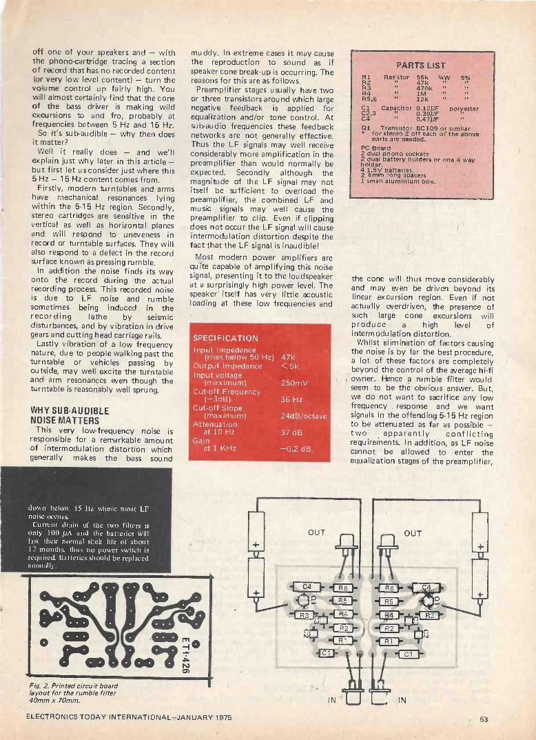
off one of your speakers and - with the phono -cartridge tracing a section of record that has no recorded content (or very low level content) - turn the volume control up fairly high. You will almost certainly find that the cone of the bass driver is making wild excursions to and fro, probably at frequencies between 5 Hz and 15 Hz.
So it's sub -audible - why then does it matter?
Well it really does - and we'll explain just why later in this article- but first let us consider just where this 5 Hz - 15 Hz content comes from. Firstly, modern turntables and arms
have mechanical resonances lying within the 5-15 Hz region. Secondly, stereo cartridges are sensitive in the vertical as well as horizontal planes and will respond to uneveness in record or turntable surfaces. They will also respond to a defect in the record surface known as pressing rumble.
In addition the noise finds its way onto the record during the actual recording process. This recorded noise is due to LF noise and rumble sometimes being induced in the recording lathe by seismic disturbances, and by vibration in drive gears and cutting head carriage rails.
Lastly vibration of a low frequency nature, due to people walking past the turntable or vehicles passing by outside, may well excite the turntable and arm resonances even though the turntable is reasonably well sprung.
WHY SUB -AUDIBLE NOISE MATTERS
This very low -frequency noise is responsible for a remarkable amount of intermodulation distortion which generally makes the bass sound
down below 15 Hz where most LF noise occurs.
Current drain of the two filters is only 100 µA and the batteries will last their normal shelf life of about 12 months, thus no power switch is required. Batteries should be replaced annually.
Fig. 2. Printed circuit board layout for the rumble filter 40mm x 70mm.
muddy. In extreme cases it may cause the reproduction to sound as if speaker cone break-up is occurring. The reasons for this are as follows.
Preamplifier stages usually have two or three transistors around which large negative feedback is applied for equalization and/or tone control. At sub -audio frequencies these feedback networks are not generally effective. Thus the LF signals may well receive considerably more amplification in the preamplifier than would normally be expected. Secondly although the magnitude of the LF signal may not itself be sufficient to overload the preamplifier, the combined LF and music signals may well cause the preamplifier to clip. Even if clipping does not occur the LF signal will cause intermodulation distortion despite the fact that the LF signal is inaudible!
Most modern power amplifiers are quite capable of amplifying this noise signal, presenting it to the loudspeaker at a surprisingly high power level. The speaker itself has very little acoustic loading at these low frequencies and
SPECI FICATION Input Impedance
(rises below 50 Hz) 47k Output Impedance Input voltage
(maximum) Cut-off Frequency
(-3dB) Cut-off Slope
(maximum) Attenuation
at 10 Hz Gain
at 1 KHz
<5k
250mV
36Hz
24dB/octave
37dB
-0.2 dB.
Zuelf gii 1
R1 R2 R3 R4 R5,6
PARTS LIST Resistor
11
Pr
56k i/aW 47k 470k " 1M 12k "
5% 11
Cl Capacitor 0.12µF polyester C2,3 Pi 0.394F C4 0.47/áF '
Ql Transistor BC109 or similar * for stereo 2 off each of the above
parts are needed. PC Board 2 dual phono sockets 2 dual battery holders or one 4 way holder. 4 1.5V batteries. 2 8mm long spacers 1 small aluminium box.
the cone will thus move considerably and may even be driven beyond its linear excursion region. Even if not actually overdriven, the presence of such large cone excursions will produce a high level of interm odu lation distortion.
Whilst elimination of factors causing the noise is by far the best procedure, a lot of these factors are completely beyond the control of the average hi-fi owner. Hence a rumble filter would seem to be the obvious answer. But, we do not want to sacrifice any low frequency response and we want signals in the offending 5-15 Hz region to be attenuated as far as possible - two apparently conflicting requirements. In addition, as LF noise cannot be allowed to enter the equalization stages of the preamplifier,
ELECTRONICS TODAY INTERNATIONAL-JANUARY 1975 53

-10
CO a 15
z w z O
w s > -2 z w
O
tc LL
-2
FREQUENCY IN HERTZ
20 30 40 50 60 80 100 200 300 400 500
35
,/ ' j /-FIRST R.C. NETWORK
SECOND R.C. NETWORK
4 ,
,
t -f L
OVERALL RESPONSE
,
i' ACTIVE FILTER SECTION
r , ,
,
i
I
le0;
jg
INPUT IMPEDANCE
i.., ..
the filter must be situated before the preamplifier. This also poses problems as the signals at this point are very low-level, and there is a danger of introducing hum which would be
merely replacing one fault by another.
THE SOLUTION To maintain response down to at
least 50 Hz, whilst obtaining 30 dB or more attenuation to LF noise, we must use a filter which has a sharp knee and an ultimate attenuation slope of 24 dB per octave. The most satisfactory (and cheapest) method of doing this is to use an active high-pass filter - and this is the approach we have used. To obviate the possibility
200k
190k
180k
170k
160k
150k
140k
130k
120k
110k
100k
90k
80k
70k
60k
50k
40k
30k
20k
10k
O
Fig. 4. Characteristics of the rumble filter.
of hum -pickup, the unit uses a battery power supply, one each for left and right channel filters, The use of separate batteries prevents earth loops and ensures that channel separation is
maintained. As current drain is very low the batteries may be expected to last their shelf life (12 months or so) and for that reason an on/off switch has not been included.
The unit fits between the turntable and the amplifier, cuts any frequency below 35 Hz and has a total attenuation of 37 dB at 10 Hz
increasing at 24 dB/octave below that.
CONSTRUCTION We built our unit onto a small
printed circuit board, but layout is not critical and other alternative methods, such as matrix or Veroboard, may be
used successfully. The signal levels involved are
extremely small (about 100 µV at 50 Hz) and for this reason a metal box is
a must if hum pickup is to be
minimized. And, as said before, two separate battery supplies should be used in order to avoid earth loops. We used a conventional four-way battery holder to hold the two sets of batteries. These holders normally connect all four batteries in series. However it is a simple matter to snip the connection between the two sets of two cells.
The phono sockets for both input and output should be insulated from the metal case. When connecting the unit we found minimum hum was introduced by earthing the turntable to the metal box and then, by taking a
separate earth from the metal box to the amplifier. However experimentation in the positioning of earths may well show that some other configuration is best for your particular setup.
54 ELECTRONICS TODAY INTERNATIONAL-JANUARY 1975
11
These
in copy possible
EX -BEA 7" ELECTROSTATIC
X MANUFACTURED STANDARD
units No circuit diagrams
the process will be
time. Therefore these
8
are
forwarded
VISUAL
cm VIEWING IN THE
240V 50HZ inspected to
or information of obtaining circuits,
to all
units are sold
USA MAINS see that
purchasers
as received
TUBE AREA
BY BUNKER INPUT no parts
is available. information,
at the
at
are We
earliest
£30
DISPLAY
-RAMO
missing. are
etc,
each.
and a
UNITS
MOTION
_ RPM AND PUNCTUATION KEYS
"EYE /
, \,
NUMERIC sins
ORATICULES. 12 cm. by 14 cm. in High POTENTIOMETERS CAPACITOR PACK 50 Brand new compo- Quality plastic. lap each. P. & P. 5p. COLVERN 3 watt. Brand new. 26K at 13p ea. nanti only EOp. P. & P. 1713:
PANEL mounting lamp holders. Red or green P.C. MOUNT SKELETON PRE-SETS. SpMOROANITE Special Brand new. 2.6; 10: ea. Miniature. PANEL mounting lamp withScrewdriver adjust 10, 6 and 2.5M (b1 2p ea. 100: 250; 500K: 1 in. sealed, 17p ea. 16MA óp ea. 1M, 500, 260 and 2 b (N Wee. Finger ad- just 10. 5 and 2.6M @ 3p ea. 1M. 600, 250
BRAND-NEW 12ín. LONG P TUBES
New stockss-newnew prNCEice.
Only £ß16O pr (whilst stock lute)
Ideal for SSTV; educational purposes. Type 12DP7A, connections, voltages etc.
BECKMAN MULTITURN DIAL BERCO 21 Watt. Brand new. 6: 10: 60; 250; and 25K @ Sp ea. Min P. & P. 10p. ohms: 1; 2.5: 10: 25 at 1Ep ea.
Price includes carriage & VAT.
Model RB. Brand new. £1.90. P. & P. 10p. STANDARD 2 map. pore. Current type 1000pf FEED THRU CAPACITORS. Only
log sold in pecks of 10-309. P. & P. 10p. chokes. Large quantity LT. HT, EHT transformers and
lópea. FIBRE GLASS PRINTED CIRCUIT RECTANGULAR INSTRUMENT}} FANS.
BOARD. Brand New. Single or Double sided. INSTRUMENT Sin. Colvern 5 ohm 36p ea.: AVolt. Ex -sou, ize 41, P. 39px
i} 115
Any size 1}p per sq. in. Postage 10p per order. 50K and 100K 50p ea. Very q
Vast quantity of good quality components -NO PASSING TRADE -so we offer 3 LB. of ELECTRONIC GOODIES
for £1.60 poet paid.
(Red) f38prom LIGHT EMITTING DIODES (RHewlett-Packard.
Brand New. ed) ea. Information 5p. Holders 1p.
BOURNS TRIMPOT POTENTIOMETERS. DELIVERED TO YOUR DOOR 1 cwt. of
20: 50; 100; 200; 500 ohms: 1 ; 2:2.5; 5: 10: Electronic Scrap chassis. boards, etc. No
25K at 36p ea. ALL BRAND NEW. Rubbish. FOR ONLY £4. N. Ireland £2 extra.
ft.
CRYSTALS. Colour 4.43MHz, Brand New £1.25 ea. P. & P. 10p.
RELIANCE P.C.B. mounting 270; 470: P.C.B. PACK S & D. Quantity 2 sq. -no tiny
METERS. Ernest Turner Model 402. 100 500 ohms; 10K at 36p ea. ALL BRAND NEW. Pieces. 60p plus P. & P. 20p.
micro amps. BRAND NEW. Lousy scale- FIBRE GLASS as above £1 plus P. & P. 20p. hence £2.26 ea. P. & P. 26p. VENNER Hour Meters -5 digit, wall mount
-sealed case. Standard mains. £3.75 ea. TRIMMER PACK, 2 Twin 50/200 pf ceramic;
Beehive Trimmer 3/30 pf. Brand new. Qty 1-9 13p ea, P. & P. 15p; 10-99 10p ea. P. & P. 25p: 100-999 7p ea, P. & P. free.
METERS by SWAM type M 42. ?5_9 25 P. & P. 45p. 2 Twin 10/60 pf ceramic: 2 min strips with 4 micro amp. Scaled 25-0-25 preen; 250-0- preset 5/20 pf on each; 3 air spaced preset HF Crystal Drive Unit. 19in. rack mount
260 red: linear. As new. £2 86 ea. P. & P. 37p. TRANSFORMERS. All standard inputs. 30/100 pf on ceramic base. ALL BRAND NEW Standard input with superb crystal oven
Gard/Perm/Part. 450-400-0-400-450. p180 26p the LOT. P. & P. 10p. y Labgear (no crystals) £6 ea. Carr. £1-50.
VISCONOLy50EHT CAPACITORS MA. 2 X 5.3v. £3 ea. ROTARY SWITCH PACK -6 Brand New
0.05mfd 25kv ó0p ea. 0.01mfd 5kv 40p ea.ALMA precision resistors 200K: 400K: 497K: witches 11 ceramic; 1-4 pole 2 way etc.). 0.05mfd Bkv SOp ea. 0.01 mfd 10kv ó0p ea. 3.25K, 5-6K. 13K-0.1% ó0p. P. & P. 20p. 998K: 0-1% 27p ea.;
20p BLOCK PAPER CAPACITORS AVAIL- ABLE. S.A.E. with requirements.
PHOTOCELL equivalent OCP 71, 13p ea.
MULLARD OCP7010p
FANTASTIC VALUE Miniature Transformer. Standard 240V input. 3Volt 1 amp output. Brand New. 66p ea. P. & P. 15p. Discount for quantity.
ea.
p
RELAYS
g3p;68K4 gOpea. covers 4 pole c/o 15K-
CONSTANT VOLTAGE TRANSFORMERS
1 Kilowatt etc. S.A.E. with requirements.
ea.
LOW FREQUENCY WOBBULATOR Primarily intended for the alignment of AM Radios; Communication Receivers; Filters, etc., in the range of 250 KHZ to 5 MHZ, but can be effectively used to 30 MHZ. Can be used with any general purpose oscilloscope. Requires 12V AC input. Three controls - RF level; sweep width and frequency. Price £8.50. P. & P. 35p. A second model is available as above but which allows the range to be extended down in frequency to 20 KHZ by the addition of external capacitors. Price £11.50. P. & P. 35p. Both models are supplied connected for automatic 50 HZ sweeping. An external sweep voltage can be used instead. These units are encapsulated for additional reliability, with the exception of the controls (not cased, not calibrated).
DON'T FORGET
YOUR MANUALS
S.A,E. WITH
REQUIREMENTS
YOURSCOPE INTO A DOUBLEGLE WITHE
AM OUR NEW
LOW PRICED SOLID STATE SWITCH. 2 HZ to 8 MHZ. Hook up a 9 volt battery and connect to your scope and have two traces for ONLY £8.25. P. & P. 25p. STILL AVAILABLE our 20 MHZ version at £9.75. P. & P. 25p.
20HZ to 200KHZ SINE AND SQUARE WAVE GENERATOR
In four ranges. Wien bridge oscillator thermistor stabilised. Separate independent sine and square wave amplitude controls. 3V max sine, 6V max square outputs. Completely assembled P.C. Board, ready to use. 9 to 12V supply required. £8.85 each. P. & P. 25p. Sine Wave only £6.85 each. P. & P. 25p.
LARGE QUANTITY OF
OSCILLOSCOPE & DISPLAY TUBES FROM 1" to 24"
S.A.E. FOR COMPREHENSIVE LIST All of our tubes can be supplied with nu -metal shields or Telcon nu -metal tape.
WIDE RANGE WOBBULATOR 5 MHZ to 150 MHZ (Useful harmonics up to 1.5 GHZ) up to 15 MHZ sweep width. Only 3 controls, preset RF level, sweep width and frequency. Ideal for 10.7 or TV IF alignment, filters, receivers. Can be used with any general purpose scope. Full instructions supplied. Connect 6.3V AC and use within minutes of receiving.
All this for only £8.75. P. & P. 25p. (Not cased, not calibrated.)
TYPE A Input: 12V DC
Output: 1.3kV AC 1.5MA
Price £3.46
TRANSISTOR TYPE B
Input: 12V DC
Output: 1.3kV DC 1.5MA
Price £4.70 Postage
INVERTORS TYPE C
Input: 12V to 24V DC Output: 1.5kV to 4kV AC 0.5MA
Price £8.35 & Packing 30p
TYPE D Input: 12V to 24V DC
Output: 14kV DC 100 micro amps at 24V. Progressively reducing for lower input voltages
Price £11
Unless stated- please add £2.00 carriage to all units.
VALUE ADDED TAX not included in prices -please add 8% Official Orders Welcomed, Gov.IEducational Depts., Authorities, etc., otherwise Cash with Order
Open 9 am to 6.30 pm any day (later by arrangement.)
'\ (
eie It with Acme IIL 11:NIL'Ft- A
7/9 ARTHUR ROAD, READING, BERKS. (rear Tech. College, Kings Road) Tel.: Reading 582605/65916
ELECTRONICS TODAY INTERNATIONAL -JANUARY 1975 55

The largest selection BRAND NEW FULLY GUARANTEED DEVICES
Type Price Type Price Type Price Type Price TyPe Price Type Price Type Price Type AC107 0.22 ADI61 & BC150 0.20 BD131 0.55 BF182 0.44 MJE2955 0.95 20308 0.39 2182192 AC113 0.20 ADl62(MP) 0.75 BC751 0.22 BDl32 0.66 B F183 0.44 M.JE3055 0.82 2G309 0.39 252193 AC115 0,22 ADTI40 0.55 BC152 0.19 BD133 0.72 BF184 0.28 MJF.3440 0.55 20339 0.22 2N2194 AC117K 0.32 AFI 14 0.27 Bel 53 0.31 BD135 0.44 BFI85 0.33 310E102 0.46 2G339A 0.18 2X2217 AC122 0.13 AF'I15 0.27 BC154 0.33 BD1313 0.44 BF'187 0.30 MPF104 0.41 20344 0.20 2512218 AC125 0,19 AFI16 0.27 BC157 0.20 BD1:37 0.50 13E188 0.44 MPF105 0.41 20345 0.18 2N22I9 ACI26 0,19 AFII7 0.27 BC158 0.13 BDI38 0.55 138194 0.13 OC19 0.39 20371 0.18 2N2220 AC127 0.20 AF118 0.39 BC159 0.13 BD139 0.81 138195 0.13 0020 0.70 2G371B 0.13 2512221 AC128 0.20 AF'124 0.33 BCL60 0.50 BDI40 0.86 B F196 0.16 0022 0.52 20373 0.19 2X2222 AC132 0,16 AF125 0.33 BC161 0.55 BD155 0.88 8E197 0.16 0C23 0.34 2G374 0.19 2X2368 AC134 0.16 AF126 0.31 BC367 0.13 131/175 0.66 BF200 0.50 0C24 0.62 2G377 0.33 2N2369 AC137 0,16 AF127 0.31 130168 0.13 BD176 0.66 BF222 £1.05 0C25 0.42 26378 0.18 2N2369A AC141 0.20 AF139 0.33 BC169 0.13 BDI77 0.72 B8257 0.50 0C26 0.32 2G381 0.18 252411 AC141K 0.32 AF178 0.55 BC170 0.13 BD178 0.72 BF258 0.66 0028 0.55 20382 0.18 2N2412 AC142 0.20 AF179 0.55 BC171 0.16 BD179 0.77 BF259 0.94 0029 0.55 20401 0.33 2182646 ACI42K 0.28 AF180 0.55 BC172 0.16 BD180 0.77 B F262 0.61 0035 0.46 20414 0.33 2N271I AC151 0.17 AF161 0.55 BC173 0.16 BD185 0.72 BF263 0.61 0036 0.55 2G417 0.28 2N2712 AC154 0.22 AF186 0.55 130174 0.16 BD186 0.72 B 8270 0.39 0041 0.22 2X388 0.39 2X2714 AC155 0.22 AF239 0.41 130175 0.24 13D187 0.77 BF271 0.33 0042 0.27 2N388A 0.61 2X2904 AC156 0.22 AL 102 0.72 BC177 0.21 BDI88 0.77 13E272 0.88 0044 0.17 2N404 0.22 2N2904A AC157 0.27 A1.103 0.72 BC178 0.21 13D189 0.83 BF'273 0.39 0045 0.14 2N404A 0.31 2X2905 AC165 0.22 ASY26 0.28 B0179 0.21 BDI90 0.83 138274 0.39 0070 0.11 2X524 0.46 2X29055 AC166 0.22 ASY27 0.33 BCI80 0.27 BDI05 0.94 BFW10 0.66 0071 0.11 281527 0.54 2X2906 AC167 0.22 ASY28 0.28 BC181 0.27 BDI96 0.94 BF7(29 0.30 OC72 0.16 2N598 0.46 2N2906A AC168 0.27 ASY29 0.28 BC182 0.16 BDI97 0.99 BFN84 0.24 0074 0.16 2N599 0.50 2N2907 AC169 0.16 ASY.50 0.28 Bel 82L 0.16 BDI98 0.99 BFS8.5 0.33 1)075 0.17 2X696 0.14 2N29075 AC176 0.22 ASY5l 0.28 BC183 0.16 BD199 £1.05 131,2886 0.24 0070 0.17 2X697 0.15 2X29.23 AC177 0.27 AS 3'52 0.28 BCI83L 0.16 13D200 £1.05 BFX87 0.27 0077 0.28 2N698 0.27 2X2924 AC178 0.31 ASY54 0,28 BCI84 0.22 13205 0.88 BFNSS 0.24 0081 0.17 2N699 0.39 2'29.25 AC179 0.31 ASY55 0.28 BC184L 0.22 131)2001 0.88 BFY50 0.22 OCSID 0.17 218706 0.09 2N2926(G) ACI80 0.22 ASY56 0.28 BC186 0.31 13D207 £1.05 liFY51 0.22 0082 0.17 2N706A 0.10 2N2926(Y) AC1S(3K 0.32 ASY57 0.28 B0187 0.31 130208 £1.05 BFY52 0.22 0082D 0.17 2N708 0.13 2N2926)0) ACI 81 0.22 ASY58 0.28 BC:.07 0.12 13133'20 £1.10 B FY53 0.19 0083 0.22 2N711 0.33 2N2926(R) AC181K 0.32 ASY73 0.28 BC2118 0.12 13E115 0.27 BSS 19 0.17 OC139 0.22 2N717 0.39 2X2926(8) AC187 0.24 ASZ21 0.44 BC209 0.13 131,117 0.50 MX 20 0.17 00140 0.22 2X718 0.27 2N3010 AC187K 0,25 BCI07 0.14 BC2l2L 0.14 131,118 0.77 B8Y25 0.17 OC160 0.28 2N718Á 0.55 2X3011 AC188 0.24 BC108 0.14 B0213L 0.14 BF119 0.77 135Y26 0.17 00170 0.28 281726 0.31 2X3053 ACISSK 0.25 13C109 0.15 B0214L 0.18 B1021 0.50 13SY'27 0.17 00171 0.28 2X727 0.31 2N3054 ACY17 0.28 BC113 0.11 BC225 0.28 138123 0.55 BSY28 0.17 00200 0.28 2N743 0.22 253055 ACV'S 0.22 BCll4 0.17 80226 0.39 BF12.5 0.50 BS Y29 0.17 00201 0.31 2X744 0.22 ACY19 0.22 BC115 0.17 BC301 0.30 13E127 0.55 BSY38 0.20 00202 0,31 2N914 0.16 ACY20 0.22 BCllOi 0.17 B("302 0.27 13E152 0.61 BSY39 0.20 00203 0.28 2X918 0.33 Type ACY21 0.22 130I17 0.20 BC303 0.35 BE 153 0.50 BSY40 0.31 00204 0.28 2X929 0.23 AA119 ACY22 0.18 BCIIS 0.11 BC304 0.40 131,154 0.50 B81'4 0.31 (X`2(0 0.39 2X930 0.23 AA 120 ACY27 0.20 BC119 0.33, 130440 0.34 13FI55 0.77 BSY95 0.14 00309 0.44 2X1131 0.22 AA129 ACY28 0.21 130120 0.88 B04611 0.40 131, 156 0.53 1351'95A 0.14 001'71 0.48 25113.2 0.24 AAY30 ACY29 0.39 BC125 0.13 BCI'30 0.27 13F'157 0.61 B010.5 £2.20 OR 112 0.48 2X1302 0.16 AAZI:3 ACY30 0.91 80126 0.20 BOYS! 0.29 BF158 0.61 C11IE 0.55 0131'60 0.44 2X1303 0.16 BAI00 ACY31 0.31 BCC32 0.13 BCY32 0.33 BF159 0.66 C4(81 0.33 OR POI 0.44 251304 0.19 BAlI6 ACY34 0.23 BC134 0.20 B0Y33 0.24 BF'lß0 0.44 0407 0.28 020 0.55 2X 1305 0.19 BA126 ACY35 0.23 BC135 0.13 BCY34 0.28 13F'162 0.44 C424 0.28 03465 0.22 2X1306 0.23 BA148 ACY36 0.31 BC136 0.17 BCY70 0.16 13E163 0.44 C425 0.55 1'397 0.46 2X1307 0.23 BA154 ACY40 0.19 13C137 0.17 BCY7I 0.22 13F164 0.44 C426 0.39 ST140 0.14 2N1308 0.26 BA155 ACY41 0,20 130139 0.44 BCY72 0.16 13F165 0.44 C428 0.22 S'1'141 0.19 251309 0.26 BA 1.56 ACY44 0.39 BC140 0.33 130Z10 0.22 13F167 0.24 0441 0.33 T'1843 0.34 2181613 0.22 BA173 AD130 0.42 BC141 0.33 BCZI1 0.28 131,173 0.24 0442 0.33 0T16 0.30 2X1711 0.22 BYI00 AD140 0.53 BC142 0.33 130Z12 0.28 13F176 0.39 0444 0.39 ZN414 £1.20 2X1889 0.35 BY301 AD142 0.53 BC143 0.33 BD115 0.68 B1,177 0.39 0450 0.24 20301 0.21 2X188) 0.50 BY105 AD143 0.42 130145 0.50 BDI16 0.88 130178 0.33 MATI00 0.21 20302 0.21 2N 1893 0.41 BY114 AD149 0.55 110147 0.11 BD121 0.66 131,179 0.33 M AT I 01 0.22 20303 0.21 252147 0.79 BY124 AD161 0.89 BC148 0.11 BD123 0.72 13E180 0.33 8:01'120 0.21 20304 0.27 2512148 0.63 BY120 AD162 0.39 130149 0.13 BD124 0.76 BFIBI 0.33 MATI2l 0.22 2G306 0.44 2512160 0.66 1317127
LINEAR I.C's-FULL SPEC. Price
Type No. 1 25 100 + 72702 0.50 0.48 0.45 7.2709 0.35 0.33 0.30 7.2709P 0.33 0.31 0.29 72710 0.45 0.43 0.40 72741 0.40 0.38 0.35 727410 0.45 0.43 0.40 72741P 0.38 0.36 0.34 72748P 0.38 0.36 0.34 SL20IC 0.59 0.45 0.40 SL701C 0.50 0.45 0.40 SL7020 0.50 0,45 0.40 TAA2(33 0.80 0.70 0.60 TAA293 £1.00 0.95 0.90 TAA350A £1.85 £1.80 £1.70 µA7030 0.28 0.26 0.24 µA7090 0.35 0,33 0.30 µA 7l 1 0.45 0.43 0.40 TBA800 £1.50 -
NUMERICAL INDICATOR TUBES
GR116 .. .. .- £1.70 3015F Minitron £1.50 MAN 3M. L.E.D. 7.segment 0.127" £190 All indicators 0.9 + Decimal point. All side viewing. Full data for all types available on request. ZN414 .. £1.20 each I.C. Radio Roc. incl. full cir. data.
TRIPLE 66 -bit DYNAMIC SHIFT REGISTER EDSR 3166
Comprises three (36 -bit 2 0 dynamic shift registers with independent inputs and out- puts. TTL compatibility and buffered clock lines to reduce the capacitive load presented at the clock pins. A bont.strapped buffer ensures a full logic swing at the output.
£2.50 each
DTL 930 SERIES LOGIC I.C's
Ty 138930 0.15 131'932 0.16 BP933 0.16 BP935 0.16 BP936 0.16 130944 0.16 BP945 0.30 131'946 0.15 BP948 0.30 BI'951 0.70 BP962 0.15 ßT8193 0.45 B1'9)94 0.45 BP9097 0.45 131'91199 0.45 0.43 0.40 Devices may be mixed to qualify for quantity price. Larger quantity price on application. (DTL 930 Series only),
Price
0.14. 0.15 0.15 0.15 0.15 0.15 0.28 0.14 0.28 0.65 0.14 0.43 0.43 0.43
118) + 0.13 0.14 0.14 0.14 0.14 0,14 0.25 0.13 0.25 0.60 0.13 0.40 0.40 0.40
VOLTAGE REGULATORS TO.3 Plastic 1.5 Amps µ5.781351L129 5V (Equiv. to
MVRSV) µA.781.211.130 12V (Equiv. to
MVR12V) .. µA.7815/L131 IÁV (Equiv. to
MVR15V) .. .. ..
£1-76
£I-76
£1.76
DUAL -IN -LINE SOCKETS 14 & 16 Lead Sockets for use with DlAL- IN-LINE 1.0's. TWO Ranges PROFES- SIONAL & NEW LOO1' COST. l'R(1F. TYPE No. 1-24 25-99 l)8)up. TSO 14 pin type 33p 30p 27p TS016 38p 35p 32p LOW COST No. BPS 14 16p 14p 12p BPS lli 17p 15p 13p BPS 8 spin type 15p 13p lip
ALL PRICES INCLUDE VAT.
Price Type Price Type Price 0.39 2183391 0.16 2X4060 0.13 0.39 2X3391 A 0.18 2184061 0.13 0.39 25/3392 0.16 218442 0.13 0.24 2X3:393 0.16 2X4284 0.19 0.22 2N:3394 0.16 2X4285 0.19 0.22 2X3:195 0.19 2184280 0.19 0.24 2183402 0.23 2X4287 0.19 0.22 2X3403 0.23 2X4288 0.19 0.22 2183404 0.31 2184289 0.19 0.19 2183405 0.46 2514290 0.19 0.16 2X3414 0.17 2X42311 0.19 0.16 2N 3415 0.17 2X4292 0.19 0.27 253416 0.31 254293 0.19 0.27 2513417 0.31 2X5172 0.13 0.52 2513525 0.83 255214 0.60 0.23 2X3614 0.74 2N5457 0.35 0.23 2X3615 0.82 2X5458 0.35 0.23 2X3616 0.82 2X5459 0.44 0.19 2X3044 0.10 2N6221 0.75 0.23 2X3702 0.13 28301 0.55 0.23 2X3703 0.13 283025 0.46 0.23 2X3704 0.14 283112 0.46 0.17 2513705 0.13 213303 0.62 0.20 2N37)8) 0.13 25304 0.77 0.22 2N3707 0.14 28.305 0.86 0.24 2183708 0.09 28:306 0.86 0.16 2 N3709 0.10 28307 0.86 0.16 2N:3710 0.10 25:321 0.62 0.16 253711 0.10 28:3':2 0.46 0.14 253819 0.31 28322225 0.46 0.12 2X3820 0.55 28323 0.62 0.11 2X3021 0.39 28324 0.77 0.11 2X382:3 0.31 25325 0.77 0.11 2 X300:3 0.31 253'26 0.77 0.77 2X:3!814 0.33 2_8327 0.77 0.16 253905 0.31 28701 0.46 0.19 2N39Uri 0.30 403)11 0.44 0.51 2X41158 0.13 40362 0.50 0.55 2184059 0.11
DIODES AND RECTIFIERS Price 0.09 0.09 0.09 0.10 0.11 0.11 0.23 0.24 0.16 0.13 0.16 0.15 0.16 0.17 0.13 0.19 0.13 0.13 0.16 0.17
Type Price Type
BY128 0.17 0510 BY330 0.18 11547 II Y1:33 0.23 0570 BY1134 0.55 057)) B1'S38,i30 0.46 OASI 13YZ10 0.39 0585 13Y7,I I 0.33 0 590 l'3YZ12 0.33 (1.391 13YZ13 0.28 0505 13Y 7.16 0.44 05200 331"/.17 0.39 05202 BY/. 18 0.39 5010 BY'Z19 0.31 SD19 0062 X34 (0591 Eq) 0.06 N34.5 00651 (0,170- X914 79) 0.07 N911í 055 0.39 X4148 055 short 8,021
leads 0.23 SO51
Price 0.15 0.08 0.08 0.08 0.08 0.10 0.07 0.07 0.08 0.07 0.08 0.06 0.06 0.08 0.08 0.06 0.06 0.06 0.11 0.07
74 Series T.T.L. I.C's BI-PAK STILL LOWEST IN PRICE. FULL SPECIFICATION GUARANTEED. ALL FAMOUS MANUFACTURERS
Type
74(0) 7401 74112
740:3 7414 7405 7406 7407 7408 7409 7410 7411 7412 7413 7416 7417 7420 7422 7423 7425 742(1 7427 74.28 7430 74:32 7433 7437 7438 74411
7441 7442 744:3 7444 7445 7446 7447
Quantities 1 25
0.18 0.17 0.18 0.17 0.18 0.17 0.18 0.17 0.18 0.17 0.18 0.17 0.39 0.34 0.39 0.34 0.25 0.24 0.25 0.24 0.18 0.17 0.28 0,27 0.30 0.29 0.32 0.31 0.40 0.39 0.40 0.39 0.18 0.17 0.30 0.29 0.40 0.39 0.40 0.39 0.40 0.38 0.40 0.38 0.45 0.42 0.18 0,17 0.40 0.38 0.42 0.40 0.45 0.42 0.45 0.42 0.18 0.17 0.74 0.71 0.74 0.71
£1.20 £1.15 £1.20 £1,15 £1.98 £1.95 £1.20 £1.15 £1,10 £1.07
100+ Type
1
Quantities 2 5 100 +
Type 1
Quantities 25
0.16 7448 £1.10 £1.07 £1.05 74122 0.88 0.86 0.16 7450 0.18 0.17 0.16 74123 £1.58 £1.54 0.16 7451 0.18 0.17 0.16 74141 0.85 0.82 0.16 745:3 0.18 0.17 0.16 74145 £1.58 £1.54 0.16 7454 0.18 0.17 0.16 74150 £2.50 £2.40 0,16 74)10 0.18 0.17 0.16 74151 £1,10 £1.05 0.31 7470 0.32 0.29 0.27 74153 £1.20 £1.10 0.31 7472 0.32 0.29 0.27 74154 £1.98 £1.90 0.23 7473 0.41 0.39 0.35 74155 £1.20 £1.15 0.23 7474 0.41 0.39 0.35 7415(1 £1.20 £1.15 0.16 7475 0.80 0.58 0.56 74157 £1.20 £1.15 0.26 7476 0.44 0.43 0.42 741(í(I £1.73 £1.70 0.28 7480 0.74 0.71 0.64 74161 £1.73 £1.70 0.30 7481 £1.30 £1.25 £1.20 741(32 £1.73 £1.70 0.38 7482 0.90 0.85 0.80 74111:3 £1,73 £1.70 0.38 7483 £1.20 £1.15 £1.05 741)14 £2.20 £2.10 0.16 7484 £1.10 £1.05 £1.00 74165 £2,20 £2.10 0.28 7485 £2.00 £1.90 £1.80 7416(1 £2.35 £2.30 0.38 746(1 0.35 0.34 0.33 74174 £2.00 £1.95 0.38 7489 £4.00 £3.75 £3.50 74175 £1.40 £1.35 0.36 7490 0.74 0.71 0.64 74176 £1,60 £1.55 0.36 7491 £1.10 £1.05 £1.00 74177 £1.60 £1.55 0.40 7492 0.74 0.71 0.64 741811 £1.60 £I.55 0.16 7493 0.74 0.71 0.64 74181 £5.00 £4.50 0.36 7494 0.85 0.82 0.75 74182 £1.50 £1.45 0.38 7495 0.85 0.82 0.75 74184 £2.40 £2.30 0.40 7496 0.96 0.93 0.86 74190 £2.15 £2.10 0.40 7410(1 £1.50 £1.45 £1.40 74191 £2.15 £2.10 0.16 74104 0.70 0.68 0.66 74192 £2.15 £2.10 0.64 74105 0.70 0.68 0.66 74193 £2.15 £2.10 0.64 74107 0.44 0.42 0.40 74194 £1.90 £1.80
£1.10 74110 0.60 0.55 0.50 74195 £1.60 £1.50 £1.10 74111 0.95 0.92 0.90 74190 £1.73 £1.70 £1.90 74118 £1.10 £1.05 £1.00 74197 £1.73 £1.70 £1.10 74119 £1.50 £1.40 £1.30 74198 £3.45 £3.35 £1.05 74121 0.50 0.48 0.45 74199 £3.10 £3.00
100 + 0.84
£1.50 0.79
£1.50 £2.30 £1.00 £1.00 £1.75 £1.10 £1.10 £1.10 £1.65 £1.65 £1.65 £1.65 £2.00 £2.00 £2.25 £1.90 £1.30 £1.50 £1.50 £1.50 £4.00 £1.40 £2.20 £2.00 £2.00 £2.00 £2.00 £1.70 £1.40 £1.65 £1.65 £3.20 £2.90
DEVICES MAY BE MIXED TO QUALIFY FOR QUANTITY PRICE. (TTL 74 SERIES ONLY) DATA IS AVAILABLE FOR THE ABOVE SERIES OF I.C's IN BOOKLE'P FORM. PRICE 35p.
56

-the lowest prices! P.W. TELE -TENNIS
KIT OF PARTS Including all resistors, capacitors,
semi -conductors, I.C. sockets, switches and transformer
Our Usual Price £27.50 SPECIAL OFFER
£23.50 incl. V.A.T. and P. Et P.
Ne regret free pack not applicable to this offer
¿1) 120 NIXIE DRIVER TRANSISTOR Suitable replacement for 3SX 21, C 407, 2N 1893 20reb.
1 25 100 + 1.19 0.17 0.16
SIL. C.P. DIODES £p 30ImW 30 0.55 400! V(Min.) 100 1.65 Suh-Min. 500 5.50 Full Tested 1,(611 9.90 Ideal for Organ Builders.
'sil. trans. suitable for PE Organ. Metal To -I8 Egvt. ZTX300 6p each. Any Qty.
GP 100 TO3 METAL CASE GERMANIUM Vebo = 80V, Vern = 50V. LC. = 10 amps. Ptot -- 30 W. hie -= 30-170. Replaces the majority of Germanium power tran- sistors in the TIC, AD and NOT range. 1 '25 110 +
9.47 0.44 0.40
AD161/162 PNP
AI(P COMP GERM TRANS. OUR LOWEST PRICE OF 75p PER P.4/R.
GP 300 TOS METAL CASE SILICON Vcl,o = I00V. Vero = 60V LC. = 15 amps. Plot =
1151V. hfc - 20. 100'T. 1A1Hz. Suitable replacement for 2N 3055, BUY 11 or BDY 20.
1 25 1161+ 0.55 0.53 0.51
LOOK FOR OUR
AUDIO it ELECTRONIC
COMPONENTS ADVERTISEMENTS PRACTICAL WIRELESS
EVERYDAY ELECTRONICS AND
RADIO CONSTRUCTOR
QUALITY TESTED SEMICONDUCTORS Pak No.
Q I 20 Red spot transistor PNP.. Q 2 16 White spot R.F. transistors PNP .. Q 3 4 0077 type transistors Q 4 6 Matched transistors 0C44/45/81(8ID Q 5 4 0075 transistors .. .. .. Q 6 5 0072 transistors .. .. Q 7 4 AC128 transistors PNP high gain .. Q 8 4 AC126 transistors PNP .. .. Q 9 7 OC81 type transistors .. QI0 7 0071 type transistors Q11 2 ACI27/128 Complementary pairs
PNP/NPN .. .. Q12. 3, AFII6 type transistors .. .. Q13 3 _1/317 type transistors .. .. Q14 3 00171 H.F. typo transistors Q15 7 2X2926 Sil. Epoxy transistors
mixed colours QI7 5 NPN 2xST.141 & 3xST.140 .. QI8 4 MADT-S 2 x MAT 100 & 2 xMAT
120 .. Qí9 3 MADT'S 2xMAT TOI & I x111AT
121
Q20 4 OC44 Germanium transistors A.F... Q21 4 ACI27 NI'N Germanium transistors Q22 20 NKT transistors A.F. R.F. coded .. Q23 10 (íA202 Silicon diodls sub -min. .. Q24 8 OA81 diodes .
Q25 15 IN914 Silicon diodes 75PIV 75mA. .
Q26 8 OA95 Germanium diodes sub -min IN09
Q27 2 1OA PIV Silicon rectifiers 1S425R .. Q28 2 Silicon power rectifiers BYZ13 Q29 4 Silicon transistors 2x 2N096, 1X
2x697, I x21698 .. Q30 7 Silicon switch transistors SN706
NPN Q31 6 Silicon a wit eh tronsi..t ors 2x708,
11'N Q32 3 PNP Silicon transistors 2x211131,
1 x2Xt132.. Q33 3 Silicon NI'N transistors 2X1711 (334 7 Silicon NI'N transistors 2X2309,
50031Hz (code 1'397) Q35 3 Silicon I'NP TO -5. 2x212904 &
1 x2\29115.. Q3(1 7 2N3646 TO.18 plastic 311031Hz NPN Q37 3 2X:3033 11'X Silicon transistors 1,138 7 PNP transistor, 3x2N3703,
2 x 23370.2.. .. .. . .
Price £p
0.55 0.55 0.55 0.55 0.55 0.55 0.55 0.55 0.55 0.55
0.55 0.55 0.55 0.55
0.55 0.55
0.55
0.55 0.55 0.55 0.55 0.55 0.55 0.55
0.55 0.55 0.55
0.55
0.55
0.55
0.55 0.55
0.55
0.55 0.55 0.55
0.55
FULL RANGE OF ZENER DIODES VOLTAGE RANGE 2-33V. 416ám (D0.7 Case) 12p ea. I ¡1V (Top -Hat) l8p eu. 101V (SII -10 Stud) 32p en. 555 I.C. 65o each
NEW 8th EDITION 250 pages
TRANSISTOR EQUIVA- LENTS BOOK. A complete cross reference and equiva- lents hook for European, American and Japanese Transistors. Exclusive to BI - PAN £1.85 each.
A LARGE RANGE OF TECHNICAL AND DATA BOOKS ARE NOW AVAIL- ABLE EX. STOCK. SEND FOR FREE LIST.
MAMMOTH I.C. PACK APPROXIMATELY 200 PIECES ASSORTED MANUFACTURERS FALL-OUT INTE- GRATED CIRCUITS INCLUDING LOGIC 74SERIES LINEAR and AUDIO AMPLIFIERS MANY CODED also SOME UNKNOWN
TYPES -YOU TO IDENTIFY PAK NO. M.I.C. 200
PRICE £l as per PAK including p & p & .V.A.T.
KING OF THE PAKS Unequalled Value and Quality
SUPER PARS N SEMIICON UCTORS D
Money back refund if not satisfied
Pak No.
U 1
U 2
U3 U 4
U 5
U 6
U 7
U8 U 9
U10 Ull U13 U14 U15
UI6 U17
018 019 020 021 023 U24
U25
026 029 032 033 U34
035 036 037 1'38 039 040 043 U44
045 046 U47
U48
049
Description
120 Glass Sub -Min. General Purpose Germanium Diodes Mixed Germanium 'transistors AF/RF .. ..
75 Germanium Gold Bonded Sub -Min. like 055, 0A47 Germanium Transistors like ()CAI, AC128 ..
60 200mA Sub -Min. Silicon Diodes 30 Sil. PlanarTrans. NON like 12SY95A. 2N706 .. 16 Si!. Rectifiers TOP -HAT 750mA VLTG. RANGE up to 1000 511 Sil. Planar Diodes 1)O.7 Glass 250mA like 0A200/202 .. .. 20 Mixed Voltages, l Watt Never Diodes .. .. 20 B.AYS0 charge storage Diodes DO -7 Glass .. ..
PNP Sil. Planar Trans. TO.5 tike 211132, 252004 .. .. 30 PNP-NPN Sil. Transistors 0C200 & 2S 104 .. .. ..
150 Mixed Silicon and Germanium Diodes .. .. .. .. NPN Sil. Planar Trans. TO -5 like BFV5I, 2X697 .. ..
10 3 Amp Silicon Rectifiers Stud Type up to 1000P1V .. .. 30 Germanium PNI' AF Transistors TO -5 like ACY 17-22
8 6 Amp Silicon Rectifiers BYZ13 Typo up to 600 PIV .. , .
Silicon NPN Transistors like BC1118
12 1.5 Amp Silicon Rectifiers 'l'op Hat up to 1000 PIV .. .. 30 5F. Germanium Alloy Transistors 2G300 Series & 0071 ..
MADT's like MHz Series PNP Transistors 20 Germanium I Amp Rectifiers (11M Series up to 300 PIV .. 25 31X/MHz NPN Silicon Transistors 2N708, BSY27 .. .. 30 Last Switching Silicon Diodes like 1x914 Micro -Min. .. 10 1 Amp SCR's TO.5 can, up to 6110 l'IV CRSI/25.600 .: 25 Zener Diodes 4101mWW 00.7 case 3-I8 volts mixed .. .. 15 Plastic Case. I Amp Silicon Rectifiers IN4000 Series .. 3(1 Silicon PNP Alloy Trans. TO -5 l3CY26 25302/4 .. .. 25 Silicon Planar 'Transistors l'NP TO -I8 2X2906 .. .. ..
Silicon Planar NPN Transistors TO -5 BFY50/51/52 .. .. 30 Silicon Alloy Transistors SO.2 PNP 0C200, 2S322 .. .. 20 Past Switching Silicon Trnn, NPN 40031Hz 2x:3011 .. .. 31) RF. Germ. PNP Transistors ºNI 30313 TO -5 .. .. .. 30 Dual Transistors 6 lead TO -5 2X2060 .. .. .. 25 Sil. Trans. Plastic TO -I8 A.F. 1C113/114 .. .. ., 20 Sil. Trans. Plastie T0.5 BC115/110 .. .. .. ..
7 35 SCR. 1'1)611 up to 90)1'1 V -. .. .. .. .. 20 Unijunction transistors similar to '1'1543 .. .. .. .. 10 'TO220AB plastie trias+ 50V (3A
9 NPN Sil power transistors like 213055 .. .. .. .. 12 NPN Sil. plastic power trams. 11111V like 2x5294/52416 ..
Price
0.55 0.55 0.55 0.55
0.55
0.55
0.55 0.55
0.55 0.55 0.55 0.55
0.55 0.55
0.55 0.55 0.55 0.55 0,55 0.55 0.55 0.55
0.55
0.55
1.10
0.55
0.55
0.55
0.55 0.55 0.55 0.55 0.55 0.55 0.55 0.55 1.10 0.55 1.10 1.10
1.10
Code. Nos. mentioned above are given as a guide to the type of device in the pak. The devices themselves are normally unmarked.
FREE One 55p Pak of your own choice free with orders valued £4 or over.
INTEGRATED CIRCUIT PARS
Manufacturers "Fall Outs" which include Functional and l'art Functional !'nits. These are classai an 'out of -spec' from the maker's very rigid specifications. but are ideal for learning about 1.C.'s and experimental work.
Pak No. Contents Price Pak No. Contents Price UIC(6)=. 12 x 74091 UIC01=12x74111 U1CO2,- 12 X7402 U1CO3=12 x 7403 U1C04=12 x 74114 UIC0.5o12X7405 UIC06=8 X7400 UIC07=8 x 7407 01040=12 X7410 111020=12 X7420 UIC30=12 x 7430 UIC40=12 x 7440 UIC41=6 x 7441 UIC42=5 x 7442 UIC,43=5 x 7443 UIC44=5 X7444 UIC45=5 x 7445
0.55 0.55 0.55 0.55 0.55 0.55 0.55 0.55 0.55 0.55 0.55 0.55 0.55 0.55 0.55 0.55 0.55
01(W3'. 5x7446 01 C4ß --- 5 x7448 l'IC50--12,.74511 17IC51==12x 7451 0IC53=12x7453 1'1054=12 x 7454 01060- 1.2 x7460 UIC70= 8 x 7470 01072=-8 x 7472 1'1C73 =8 x 7473 ÚI074=8 X 7474 111C76=8 X7476 Ú1C80=5 x 7480 UIC81=5 x 7481 01082=5 x7482 UIC83=5 x 7483 UIC80=5 x7486
0.55 0.55 0.55 0.55 0.55 0.55 0,55 0.55 0.55 0.55 0.55 0.55 0.55 0.55 0.55 0.55 0.55
Pak No. Contents Price
U1C90=5 x 74160 UIC91=5x7491 UIC92 5x74112 0109:3= 5 x7493 01094 5 x 7494 01095. -5 x7495 1.71C913=6 x7496 UIC100-5x74100 UIC121-=5 x74121 UICI41 =5x74141 UICI51=5 x74151 UIC154 =5 x74154 0IC193-=5 x 74193 U1C199=5 x 74199
0.55 0.55 0,55 0.55 0.55 0.55 0.55 0.55 0.55 0.55 0.55 0.55 0.55 0.55
UICXI=25 Asaorted 74'a £1,05
Palm cannot be split, but 25 assorted pieces (our mix) is available as PAK UIC Xl.
1974 CATALOGUE NOW READY lop
CADMIUM CELLS ORP1248p
NEW LOW PRICED TESTED S.C.R's PIV
.5(1
100 21)0
4(61 1i0(1
800
IA 3A 5A 5A 7A 10A 16A 305 T05'T066T066'T(364T(148 T048 TO48 T048 0.26 0.28 0.39 0.39 0.52 0.55 0.59 £1.27 0.28 0.37 0.52 0.52 0.55 0.64 0.70 £1,54 0.39 0.41 0.54 0.54 0.63 0.67 0.83 £1.70 0.48 0.52 0.62 0.62 0.74 0.83 £1.03 £1.93 0.59 0.63 0.75 0.75 0.85 £1.07 £1.38 - 0.70 0.77 0.88 0.88 0.99 £1.32 £1.65 £4.40
SIL. RECTS. TESTED PI1':t00pn-A750nr1 IA 1.5A 3A 10A 30A
50 0.0.7 0.06 N40111 0.05 0.08 0.15 0.21 0.60 100 (1.115 007 N40112 0.013 0.10 0.17 0.23 0.75 200 0.06 0.10 .N4003 0.07 0.12 0.22 0.25 £1.00 401 1018 11.15 N4014 0.08 11.15 0.30 0.38 £1.35 600 0.09 0.17 X41615 0.1(1 0.18 0.36 0.45 £1.90 1110 0.12 0.19 N41163 0.11 0.20 0.38 0.55 £2.10
1000 0.14 0.30 x41617 0.12 0.25 0.48 0.65 £2.50 12011 - 11.35 - 0.30 0.58 0.75 £3.00
DISCS FOR USE WITH TRIALS BRIO0 (D32) 25p cook
2N3055 115 WATT SIL POWER NPN
55p EACH
2 Amp BRIDGE RECCE. 50 v RMS 35p each
100 v RMS 41p 200 v RMS 45p 400 v HMS 1000 v HMS 55p 84e 16 mm X 16 mm.
D1699 NPN SILICON DUAL TRANSISTOR (Similar to 2N2060)
1 25 100 + 0.28 0.26 0.23
LINEAR INTEGRATED CIRCUIT PAKS ULIC700 ULIC710 ULIC741 ULIC747 ULIC748
10-709 7 - 710 7 - 741 5 - 747 7 - 748
0.55 0.55 0.55 0.55 0.55
10 amp POTTED BRIDGE RECTIFIER
on heat sink. 100PIV.99p each
TRIACS VBOM 2A SA l0A
TO -5 TO -66 TO -48 £ £ £
100 0.33 0.55 0.83 200 0.65 0.66 0.99 400 0.77 0.83 1.21
f.«. No 705
B/-P.4/ff P.O. BOX 6, WARE HERTS p us to 4c xml pa u,,i add 11p Ovryo:,, J,1 ' ., le, ,,.,,n.i "Si, 1':,,h w,/h ,,,,I,'
Guaranteed Satisfaction or Money Baclt
57

GIRO NO. 331 7056 C.W.O. only. P. & P IOp on orders below L5
Discount, L10-10%, [20-15°/a (except net Items) Export Order welcome (VAT (ree)
Official Orders accepted from Educational & Government Departments
ALL PRICES INCLUDE VAT
SPECIAL RESISTOR KITS IPr,ces , nclude peat 6 packinel 10E12 1W KIT. 10 of each E12 value, 22 onms-I M, a total of 570(CARBON FILM 5%), £3 63 net 10E12 {W KIT, 10 of each 812 value, 22 ohms -1M, a total of,570(CARBON FILM 5" I, O05 net 25E12 1W KIT: 25 of each E12 value, 22 ohms -1M, a total or 1425 (CARBON FILM 5%), L8 35 net 25E12 s W KIT: 25 of each E12 value, 22 ohms -1 M. a total of 1425 (CARBON FILM 5°°l, Li 46 net 20E12 7W KIT. 20 of each E12 value, 22 ohms -2M2, a total of 1220 (METAL FILM 5°,°I, LI I OS net
ALL QUANTITIES SPECIFIED ABOVE ARE APPROXIMATE. MULLARD POLYESTER CAPACITORS C2$0 SERIES 250V P.0 Mounting: O OIuF, 0 015pF, 0 022uF, 0 033µF, 0'047µF, 30, 0 068uF, 0 Ii/F, 45p. 0 154./F, 4íp, 0 22µF, hp. 0 338F, Bp. 0 470, Op. 0 68uF, 11p. IuF, ISp.I 56F,23p.2 2µF. 26P. MULLARD POLYESTER CAPACITORS C216 SERIES 400V: 0 0010, 0 00155F. O 00225F, 0.00335F, 0 00475F, 1{C. 0 00680, O 010F, 0 01511F, 0 O22uF, 0 033µF, Sip. 0 0470, 0 0685F, 0 I5F, 46p 0 I55F, 6tp. 0 22µF,81p.0 3314F, 11p. 47uF,I4p. 160V: O 014JF, 0 0155F, 0 0225F, 3p. 0 0475F, 0 068µF,) p. 0 IsP, 41p. 0.155F, Sp. 0 225F, 507.0 335F,6¡p.0 47µF, hp. 0 68µF, lip. I uF, 14p. MINIATURE CERAMIC PLATE CAPACITORS 50V: (5FI 22 27, 33, 39. 47, 56, 68, 82, 100, 120, ISO, 110, 220, 270, 330, 390, 470, 560, 680, 820,1K. I KS, 2K2, 3K3, 4K7, 6KB, (uF) 0 01, 0 OIS, 0 022, 0 033, 0047, 24p. each. 0 30V, 455, POLYSTYRENE CAPACITORS 160V 5°/t (pF) 10, IS, 22, 33. 47, 68, 100, ISO, 220. 330, 470, 680, 1000, 1500, 2200, 3300. 4700,6800, 10.000, 45 p.
RESISTORS CF-Hleh Stab Carbon Film, 5°, MF-rligh Stab Metal Film, W. T pe Rine* 1-99 100-499
1
CF 22 -IM I 0 75 CF 22.2M2 I 0 75 Ce 21IM I 075 MF 10IM7 1 I 54 MF 10.2M2 2 143
Ì MF 10IOM 3 198 2 MF 10.10M 4 S 3 52
5%. 500-999 1000 Sise mm 0 60 0 60 0 55 39r10S 060 0 SS S 5x16 I 32 I I Sel 1 2i 099 42108 181 1 65 6 603 3 08 2 75 8x175
For value m,e,ng prcN, Platte refer to our catalogue. VALUES AVAILABLE-E12 Ser,es on la
,pr.ce .n pence each) INet prion above 1001
PRESET SKELETON POTENTIOMETERS MINIATURE 0 25W Vertical or hor'tontal 6p each IK, 2K2, up to IM O. SUBMIN 0 05W Vert,ca1. 100 n to 220K R Sp each
B. H. COMPONENT FACTORS LTD. Miniature Mullard Electrolytic. I.OuF 63V 6}p 68uF 16V 6}p
I SuF 63V 65p 6811F 63V lip 2 lµF 63V 6}p I00uF I0V 64) 3 3uF 63V 6{p 100uF 25V 6ip 4.0uF 40V 6}p 100uF 63V 14p 4 7uF 63V hp 1500F 16V 61p 6 BuF 63V 6}p 150uF 63V 15p 8.0uF 40V 6)p 220uF 6 4V 6{p OuF 16V 65p 220uF 10V 6,9 05F 25V 65p 220F 16V Pp 05F 63V hp 2205F 63V 21p 55F 16V 65p 33051F 16V 12p 5µF 63V 6{p 3305F 63V iSp 60F 40V 6;p 4704,8 6 4V 9p
22uF 25V 65p 4705F 40V 209 22uF 63V 65p 680µF 16V ISp 32µF 10V 65p 6805F 40V 1Sp 33µF 16V 659 1000uF 16V 205 33uF 40V 659 1000µF 25V lSp 325F 63V 65p IS00uF 6.4 ISp 47uF 10V 65p 15005F I6V 2Sp 475F 25V 65p 22005F 10V 1Sp
141.17uF 63V Bp 3300uF 6'4 26p
VEROBQARD 0 1 o Is 21 x 5" 28p 18p 24 x 36" 26p 19p 33 x 5" 31p 33p 31 e 3}" 28p 28p 25 x I" 7p 7p 2+ x 5" (Plàinl - 14p 25 x 31" (Plan) - lip 5 x 31" (Plain) - lip Insertion tool 59p S9p Track Cutter 449 449 Pins, Pkt. 25 IOp 10p
ETI) e1 CHEDDINOTON R A NR. LEIGHTON BUZZARD, EDA, LU7 SAO
Tel.. Chedd,ngtoh 668446 1 td. Code 02961 PLEASE WRITE FOR FREE CATALOGUE
4K7, 10K. etc.
POTENTIOMETERS Carbon Track 51( 1) to 2M ti, log or hn. Single, 16,p Dual Gang 46p. Log Sin le w'th switch 269 Slider Pots. 10K, 100K, 500K 30mm. 349. 45mm, 47p, 60mm. SSp. (Semi -fog)
TRANSISTORS AC127 165p 13C212L 12p AC12B 12p BC213L 12p BC107 I I p BC214L 17p BC108 12p 0C44 18p BC109 13p OC71 13p 8C148 lip OCal 169 BC I49 12p 0C170 13p BC182L lip TIS43 33p BC183L 12p 2N2926 11p BC184L 139 2N3702 IIp
DIODES 1N4001659 1N4002 75p IN4003 9p íN4004 95p 1N4005 lip
1 N4006 14p IN914 7p IN916 7p BA100 IOp OAS 42p 0A47 Op OASI Ilp OA200 Bp
PLUGS DIN 2 Pin 12p
3 P,n 13p 5 Pin 180° ISp Std. Jack 145p 2.5mm Jack lip Phono 5,9 SOCKETS DIN 2 Pin 10p
3 P,n 10p 5 Pin 180° 12p Std. Jack 14)5 2.5mm lack Ilp Phono S{p
ELECTROLYTIC CAPACITORS. Tubular £ Large Cant fuFlv,: 1!25. 2121. 4/25, 4 7I I0. 5125, 8/25. 10110. 10'50. 16125.
22163. 25125, 2550. 32/25. 50'25. 100;10. 100!25. 6;p. 50150, 8p. 100/50. 200;25. I1p. 250,50, 18p. 500;10. 11p. 500125. ISp. 500150. 18p. 1000;10. 15p 1000125. lip. 1000(50. 40p. 2000110, 20p. 10001100 90p. 200025 30p 20001100. 95p 2500125, 3Ro. 2500;50, 629. 3000150, 805. 5000125, 66p. 5000'50,£1,10 HI-VOLT: 4(450, 14p. 8;350, 19p. 5,450 20p. 16;350, 22p. 161450. 23p. 321350. 33p. 50;250. 10p. 100'500, 88p.
METALLISED PAPER CAPACITORS 250V 0 05,4F, 0 1...F, 6p. 0 25, 6p. 0 5µF. 7;p. I 5F. Op. 500V. 0 025, 0 05, 6p 0 1, 6p. 0 25. 7'p 0 5, 9p 1000V: 0 01, IIp. 0 022. 13p. 0 047. 0 I. 1Sp. 0 22, 235.0 47, 18p.
Integrated Circuits µA709C Sop sA741C SSp µÁ723C LI 2N414 L1.32p
Screened Wire, Metre B}p NEW KIT 5ET2 }W METAL Twin Screened Wire. Metre 1 p FILM 5% ULTRA LOW NOISE Stereo Screened Wire, Metre 12p NEW RESISTORS WITH FULL Connecting Wire, All colours, Metres 1,p COLOUR CODING 5 EACH Neon Bulb, 90V W're Ended 5 for 249 E12 VALUE l0f3-1M, TOTAL Panel Neon, 240V Rrd, Amber, Cie I. 205 305£2.71 e
EM!J CHANTIClEER * READ: TIME & ALARM * ELECTRONIC 'BEEP' ALARM TONE * TEN MINUTE 'SNOOZE' FEATURE * BRIGHT, CLEAR DISPLAY * NO MOVING PARTS * EXECUTIVE STYLING * SOLID STATE RELIABILITY
Dìgìtal clock
D
The heart of the CHANTICLEER is a tiny electronic package containing thousands of transistors which divide the 50 cycles/second mains frequency into precise time units. The clock "movement" in fact has no moving parts to wear out or tick or tock or hum or click.
RECOMMENDED + VAT. PRICE
COMPLETELY ELECTRONIC NO MOVING PARTS
Alarm Has a.m. or p.m. setting with alarm on/off indicator. A gentle electronic 'beep' tone with special snooze feature that resets the alarm for ten-minute intervals. The snooze' is activated by simply tilting the clock forward and then releasing. Upon cancelling, the alarm can be immediately reset for the same time next day.
BYWOOD ELECTRONICS, 181 Ebberns Road, Hemel Hempstead, Herts. HP3 9RD. Tel: 0442-62757
58 ELECTRONICS TODAY INTERNATIONAL-JANUARY 1975

ETI TOP PROJECTS Shown below are the contents of the ETI TOP PROJECTS special 100 -page issue containing reprints of over 20 of the most popular projects from past issues of ETI. Thousands have already been sold. Be sure to get your copy while there are still supplies.
ON SALE AT YOUR NEWSAGENTS
AUDIO
75p 100W GUITAR AMPLIFIER 6 Rugged, high quality circuit handles 100W continuous power MIXER PREAMPLIFIER 11
Simple circuit for use with 100Wguitar amp MASTER MIXER Major project gives professional performance
SIMPLE AMPLIFIER 1,541/ amplifier using discrete components
SIMPLE LOUDHAILER A few components -a lot of power
38
83
90
TEST GEAR
WIDE RANGE VOLTMETER Solid-state circuit has 22 ranges - from l0mV to 1000V a.c./d.c TRANSISTOR TESTER Basic circuit measures gains up to 1000
FET DC VOLTMETER Cheap -to -build with 10M2 input impedance
OSCILLOSCOPE CALIBRATOR A circuit to build into your 'scope
AUDIO ATTENUATOR Provides 0-59dB attenuation in 7dB steps
14
23
24
65
84
FOR THE MOTORIST
ELECTRONIC TRANSISTORISED IGNITION A popular design to improve your car's performance THE REVEALER is there metal or filler underneath the paint? BRAKE LIGHT WARNING Dashboard indicator shows when brake lights are o.k.
30
60
76
FOR THE PHOTOGRAPHER
PHOTOGRAPHIC TIMER 26 Provides accurate timing of photographic processes
SOUND OPERATED FLASH 66 Can be triggered by anything from a dropping pin to a thunderclap
FOR THE HOME
TEMPERATURE METER 19 Gives a meter reading - even at a distance UHF TV PREAMP 20 One transistor circuit pepa up weak signals
BURGLAR ALARM Be A variety of alarm circuits are described
MISCELLANEOUS
LOW POWER LASER 62 Build your own laser for about £700 COIN COLLECTOR METAL LOCATOR 70 Simple but sensitive circuit EASY WAY TO MAKE P.C. BOARDS 80 Solves messy painting and hours of time TECH-TIPS 92 A collection of circuit ideas for the experimenter
IN CASE OF DIFFICULTY, USE THIS FORM TO OBTAIN YOUR COPY DIRECTLY FROM US.
To: ETI TOP PROJECTS BOOK, Electronics Today International, 36 Ebury Street, London SW1W OLW.
Please send me a copy of the ETI Top Projects Book. I enclose a cheque/P.O. for 85p (payable to Electronics Today International) which includes 10p postage (applicable to surface mail world-wide).
Name
Address
Jan 75 I
ELECTRONIC SPEED CONTROL FOR MOTORS
Continued from page 51.
maximum rms voltage available to the motor under half -wave conditions is less than for full -wave, the motor should be designed for use under these conditions to obtain maximum speed.
CONTROL OF PERMANENT MAGNET MOTORS
As a result of recent developments in ceramic permanent -magnet materials that can be easily moulded into complex shapes at low cost, the permanent -magnet motor has become increasingly attractive as an appliance component. Electronic control of this type of motor can be easily achieved using techniques similar to those just described for the universal motor. Figure 16 is a circuit diagram of a
control system to control permanent -magnet motors presently being used in blenders. Potentiometer R3 and diode D1 form a dc charging path for capacitor Cl; variable resistor R1 and resistor R2 form an ac charging path which creates the ramp voltage on the capacitor. Resistor R4 and diode 02 serve to isolate the motor control circuit from the ramp generator during the positive and negative half -cycles, respectively.
A small amount of cycle skipping can be experienced at low speeds using this control, but not enough to necessitate further development work. Since the voltage generated during off time is very high, the thermal runaway problem does not appear at all.
HEATER CONTROL AND TIMERS The circuit shown in Fig.2 or 3 could
well be made to control heaters in domestic appliances without any modifications.
If the capacitor CT in Fig.3 is made very large a timer results. The time delay is set by the value of CT and the variable resistor RT.
We must emphasis that this article is not intended as a constructional one and component values cannot be supp- lied. However a number of practical circuits covering speed control are scheduled for the magazine in two months.
ELECTRONICS TODAY INTERNATIONAL-JANUARY 1975 59

ELECTRONICS PART 11b -its easy:
This month we continue our dis- cussion of Amplification by looking at the basics of the transistor amp- lifier.
Fig.9. The basic structure and symbols for the two elementary transistor types. EMITTER
Fig. 10, The actual transistor chip is indeed tiny - as these enlargements show. The scales at left half millimetre divisioñs. The smaller chip is a high -frequency small - signal transistor, mounted in a TO5 case, the other a power transistor mounted in a TO3 case.
BASE
COLLECTOR
113I- I LInpn b
b
n-p-n TYPE
THE TRANSISTOR Transistors are made from two basic
materials - germanium or silicon. These two materials are known as
semiconductors because they are neither good insulators, nor good conductors. That is, they are somewhere in between.
Germanium was used for early transistors, but has largely (although not entirely) been replaced by silicon in modern devices. Although there are some important differences between transistors constructed from these two materials, the basic theory, as follows, is the same.
The basic pure material is modified by adding a controlled amount of impurities called dopants, to form two new materials, one (called P type) having a deficiency of electrons and one (called N type) having a surplus of electrons.
If two pieces of these differently doped materials are intimately joined we have what is called a PN junction. Such a junction of P and N materials will conduct current more readily in one direction than in the other - it is
in fact a rectifier, or in other words, a
semiconductor diode. Current flow occurs when the P type
material is made more positive than the N type material. The physics. involved in this phenomenon are complex, but of little interest at this stage. We are only interested in the fact that it happens.
60 ELECTRONICS TODAY INTERNATIONAL-JANUARY 1975
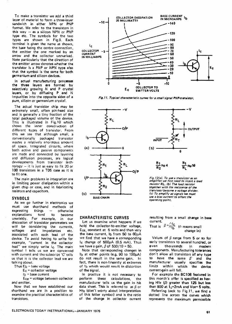
To make a transistor we add a third layer of material to form a three -layer sandwich in either NPN or PNP format. We refer to the transistors in this way - as a silicon NPN or PNP type etc. The symbols for the two types are shown in Fig.9. Each terminal is given the name as shown, the base being the centre connection, the emitter the one marked by an arrow and the collector unmarked. Note particularly that the direction of the emitter arrow denotes whether the transistor is a PNP or NPN type also that the symbol is the same for both germanium and silicon devices.
In actual manufacturing processes the three layers are formed by selectively growing N and P crystal layers, or by diffusing P and N impurities into the opposite sides of a
pure, silicon or germanium crystal.
The actual transistor chip may be extremely small, often pin -head size and is generally a tiny fraction of the total packaged volume of the device. This is illustrated in Fig.10 which shows the inner construction of different types of transistor. From this we see that although small, a
conventionally packaged transistor wastes a relatively enormous amount of space. Integrated circuits, where both active and passive components are made and connected by layering and diffusion processes, are logical developments from transistor tech- nology - it is just as easy to fit 20 or 100 transistors in a T05 case as it is
to fit one.
The main problems in integration are in limiting power dissipation within a
given chip or case, and in fabricating resistors and capacitors.
SYMBOLS As we go further in electronics we
must use shorthand methods of expressing things - otherwise explanations tend to become unwieldy. For example, in our discussion of transistor parameters we will be considering the currents, voltages and impedances etc. associated with each lead of the device. To avoid having to write for example, "current in the collector lead" we simply write lc. The main symbol I tells us we are concerned with current and the subscript 'C' tells us that it is the collector lead we are talking about.
Thus Eb = base voltage Ec = collector voltage lb = base current Ece = voltage between collector
and emitter. Now that we have established our
shorthand we are in a position to examine the practical characteristics of transistors.
-10
It COLLECTOR _5 CURRENT IN MILLIAMPS
COLLECTOR DISSIPATION 25 MILLIWATTS
BASE CURRENT I
IN MICROAMPS b
-140
-120
- 100
- 90 - 80 - 70 - 60 - 50
- 40 - 30 -20 - 10
0
Ec
-5 COLLECTOR TO EMITTER -VOLTS
-10
Fíg,17. Typical characteristic curves for a small signal PNP-traneistor,
O/P
BIAS CHAIN
CHARACTERISTIC CURVES Let us examine what happens if we
hold the collector -to -emitter voltage, Ece, constant at -5 volts and then vary the base current, lb from 50 to 60µA we find that we have a corresponding lc change of 500µA (0.5 mA). Thus we have a gain, ß of 500/10 = 50.
Note that corresponding changes in lb at other points (e.g. 90 to 100µA) do not result in the same gain. In fact, there is non -linearity at extremes of lb which would result in distortion of the signal.
In practice it is not necessary to perform these calculations, the manufacturer tells us the gain in his data sheet. This is referred to as ß or Hfe (don't worry about interpretation of this latter symbol) and is the ratio of the change in collector current
INPUT
(b)
R1 4
R 2
Ri
Fig.12(a). To use a transistor as an amplifier we first need to insert a load resistor RL. (b) The load resistor together with the resistance of the transistor become a voltage divider. (c) To amplify ac signals we must use a bias current to offset the operating point.
resulting from a small change in base current.
_ AIc That is ß - (A means small
change in)
Values of ß range from 5 or so for early transistors to several hundred, or even thousands in modern components. Manufacturing tolerances don't allow all transistors of any type to have the same ß' and the manufacturer usually specifies the limits within which the device current -gain will fall.
For example the BC108 featured in this month's offer is specified as hav- ing Hfe (13) greater than 125 but less than 900 at 1 c=2mA and Vice= 5 volts.
Referring back to Fig.11, we find a dotted line across the curves which represents the maximum permissible
ELECTRONICS TODAY INETRNATIONAL-JANUARY 1975 61

ELECTRONICS -it's easy! IC LOAD LINE FOR VALUE OF
MAXIMUM - FLOWING WHEN
Ec=0
(Ic=w)
RL CHOSEN
c MAXIMUM WHEN
Ic=O Ec = V (FOR RLMUCH
LESS THAN 'RESISTANCE' OF TRANSISTOR)
Fig. 13. Output impedance of the stage is equal to the value of RL. RL is generally chosen
to be about one -tenth of the input impedance of the following stage provided that í .12/42 R
does not exceed the rated device dissipation. The load line is then drawn and operating
point Q determined as detailed in the text.
power dissipation for the device. This is determined by the maximum heat that can be dissipated without the chip being destroyed, unless the device is
cooled by a heat sink or with forced air circulation.
For example if the transistor of Fig.11 has an Ece of 5 V, then the collector current must not exceed 5 mA if the dissipation is to be less than 25 mW. Thus the user must check his design to ensure that under worst case conditions (component tolerances, power supply voltage etc.) this dissipation is not exceeded. The device must never be operated at any point above and to the right of the dissipation curve.
Thus we see that much information can be extracted from the characteristic curves.
THE BASIC AC AMPLIFIER Used alone, the transistor cannot
amplify ac waveforms. The two main limitations are its inherent rectifying action and an effect known as thermal runaway. In addition we must devise a
way of taking an output from the transistor.
The transistor may be considered as a
resistor whose value is varied by the input base current. Hence, if we place a resistor in series with the collector lead of the transistor, we will have a
voltage divider as shown in Fig. 12. The collector current, as it changes in response to changes in base current, will produce an output voltage across the series resistor. This series resistor is
called the 'load' resistor and is denoted by the symbol R L.
Note that to drive more current into the base we must raise Eb towards the collector supply voltage. The resulting
increase in IC will cause the voltage at the collector, Ec, to fall. Thus the output voltage will be the inverse of the input. In other words, the transistor connected in this fashion, changes the phase of the input voltage by 1800.
BIASING If a sine wave were to be applied to
the base of the transistor in Fig. 12a, the negative half cycles would be clipped off - the waveform would be rectified as previously explained. We can overcome this by applying a dc 'bias' current to the base such that the input signal either adds or subtracts from this current but never drives the base current to zero.
Hence the collector current will also be biased away from zero and will follow the variations in base current. In practical circuits it is not feasible to have a separate battery or power supply to provide bias, so it is usually derived from the collector supply. The most common method is by using a
voltage divider as illustrated in Fig. 12c.
Biasing can also be illustrated using characteristic curves. For any chosen RL value, there will be corresponding pairs of IC and Ec values - Ohms law again. This means for any value of R L
we can draw a line - called the load line - across the characteristic curve as
in Fig. 13. The importance of this curve is that the input signal, lb moves up and down this line. If we do not add a bias current to lb we would be operating at the bottom end, where lb
= 0, and only negative swings of lb would be amplified. By adding a
quiescent bias current we put the mean operating point at a place
midway (this is called the Q point) along the load line and both half cycles of our input signal will be amplified linearly.
The degree of distortion is decided by the extent to which the input signal varies lb up and down about the Q -point. Small signal changes will be undistorted but not large ones. One cause of this is that the gain le/lb will change at the limits.
Secondly, if the input signal increases still further, the peaks of the sine wave will be clipped, at one end by the base current reaching zero, and at the other by the collector voltage being driven to zero (this latter condition is called saturation). Hence it can readily be seen, from the characteristic curves and load line, what maximum input signal can be applied without distortion occurring.
Note that the load line must always lie below the maximum power dissipation curve.
THERMAL RUNAWAY As well as the currents lb and lc that
are designed to flow in the transistor there is leakage current through the normally reverse -biased, collector -base junction. Some of this current will flow through the base -emitter junction (actually all of it if the base is not connected) appearing as a normal signal. The apparent signal current will be amplified causing an lc of ßlb.
Now here is the danger - the leakage current is proportional to temperature. So the increased heats the transistor, the leakage current increases, Ic increases still further - and the process may continue until the transistor destroys itself.
The actual process is more involved than we have described but the explanation suffices for our purposes.
With silicon transistors leakage current is very small and of little importance but silicon has another temperature effect that produces similar, although not as serious, thermal runaway. This is that the Ebe
EMITTER RESISTANCE
Fig.14. The amplifier is stabilized against the effects of thermal runaway by adding an emitter resistor.
62 ELECTRONICS TODAY INTERNATIONAL-JANUARY 1975

ELECTRONICS -it's easy! of a silicon transistor, required for a
certain collector current, falls with temperature. Hence with a fixed input voltage the resultant le causes a rise in
temperature, which causes a decrease in Ebe required, and hence a further rise in lc - result thermal runaway.
Silicon transistors can be used over a
much wider range than can germanium but thermal runaway must be
compensated for with both types.
Fortunately this potentially damaging effect is easily overcome, in both cases, by adding a resistor into the emitter path as shown in Fig. 14. Its effect is as follows.
As the collector current rises (due to leakage current) the voltage dropped across the emitter resistor, Re, increases thus reducing the base -emitter voltage Vbe. This reduces the base current, and almost restores the collector current to its original
value. Mathematics tells us the ideal conditions to achieve stability and show that an emitter resistance roughly one sixth of the collector load resistance is about right. The bias chain values must be readjusted for this and again there are complex mathematical expressions for optimizing the values. In practice a
good choice is that the chain has values in the same ratio as the collector chain but about ten times larger.
BYPASSING Having overcome thermal runaway
conditions we now find the amplifier is nicely stable but lacks gain. This is
because the same collector current flows through the emitter resistor as
through the load resistor. Hence the gain can only be equal to the ratio of RL to Re, that is, in our case 6. And
this is completely independant of ß.
We can restore our gain by adding one more component- a capacitor across Re.
Thermal effects occur slowly by comparison with ac signals (10 Hz and above) so a capacitor connected across the emitter resistor will act as a low impedance to ac signals (thus restoring ac gain) but as a non -existant component to dc. Hence we get the best of both worlds - thermal runaway is eliminated and ac gain is
maintained. The capacitor is chosen such that its reactance is about one tenth the value of Re at the lowest frequency of interest.
Further reading: "Understanding Solid State
Electronics" Texas Instruments Ltd. Manton Lane, Bedford.
ELECTRONICS THE CIRCUIT of a typical ac
amplifier, for audio frequencies, is
given in Fig. 15. The input signal is
coupled in via a capacitor that provides dc isolation between the preceding stage and the bias network.
As the capacitor needs to be fairly large (X, less than one tenth the resistance from base to ground at lowest frequency) it is usually an
electrolytic. An electrolytic may be used as long as the positive terminal is
connected to the most positive dc potentia I.
The circuit uses the transistors in
this month's offer and may be put to work (and tested) by adding the components as shown in Fig. 16.
In effect we now have a light intensity meter which can be used to monitor the modulated content of the radiation from a fluorescent -light tube. Note that it does not measure the steady-state light radiation.
The light dependant resistor, type ORP12, provides a small amplitude 100 Hz signal when excited by the light from a fluorescent tube. The amplifier increases the signal amplitude by about forty times. The output from the amplifier may then be
half -wave rectified to provide a dc output proportional to the level of the 100 Hz light signal. This may be
measured by a normal multimeter, or alternatively, the ac signal may be fed directly to high impedance headphones. You will then hear the 100 Hz tone from the light radiation.
in practice
100µf
INPUT 0-T.
STAGE d.c.
I ISOLATING CAPACITOR
+12v
820
BC109,108,107
100µF TBYPASS
CAPACITOR
1100µF
BC1O8,108,107
TIO0pF
1
OAP12
,1
O OUTPUT
Fig.15. The addition of a bypass capacitor restores ac gain and an input capacitor provides isolation for the input. We now have e complete ac amplifier. Two or more stages can be used in series of more gain is required.
/I
OV - 5V d.c.
'1 METER RANGE
0.1µF (FAST RESPONSE) 100µF (SLOW RESPONSE)
Fig.16. The modulated light output from a fluorescent lamp may be amplified and measured by adding just a few more components. This also provides a simple test of correct amplifier operation.
ELECTRONICS TODAY INTERNATIONAL-JANUARY 1975 63

EEEtFOG'1IES by John illillefhichpatciuH
Tomorrow PETROL PRICES UPI Food Prices
Upl Cigarette Prices Upi Electronics Prices Down?
Has It ever occured to you that whereas most products in this country, in fact In the world, have suffered from price inflation, products connect- ed with the electronics industry tend to go down in price. Such things as
television sets, HiFi sets, calculators, clocks, etc, all tend to go down in price regardless of the rate of inflation. This is quite possibly because most of the raw materials used in the elect- ronics industry are cheap and reason- ably plentiful. Even those materials which are expensive or rare (such as
are used in semiconductor manufact- ure) are used in such small quantities per finished unit that the cost per unit is relatively small. If the material cost is low then the only inflationary costs involved are power and labour, thus the price of such components is based
substantially on the actual manufact- uring costs. Thus to keep prices down the manufacturer must use less of the expensive materials and at the same
time automate as much as possible. The LSI integrated circuit has meant that more functions can be packed onto a small silicone chip and there- fore fewer of those functions need to be made up from discrete components on a PCB, this cuts the component cost, PCB cost, assembly cost and testing costs.
As the finished PCB becomes simp- ler to assemble and contains fewer and fewer components other than ICs
so the economics of automated ass-
embly become more feasable. Mach-
inery already exists for automatically assembling PCBs from ICs and dis-
cretes, other machines can automat- ically make the ICs from the raw materials, yet other machines can
produce and/or purify these raw
materials. From shovelling in the basic materials at one end (which could be done automatically) to pro- ducing the finished PCB at the other end, the whole process can be done automatically and controlled by a
computer. This same computer can
also test the finished PCBs and auto-
matically reject or perhaps repair any that are below spec.
Of course, the human brain is still used in the original design and layout of the ICs and PCBs - or is it?
Computer Aided Design is now used
for optimum design in most ICs and some of the more complex PCBs.
The computer uses pre -written pro- grams and sub -routines to route the tracks of the various parts of the IC and to calculate the amount of mat- erial required to give the resistance or capacitance needed. Similarly, the computer can help out with the theoretical circuit design by simulat- ing the circuit under any conditions and changing theoretical values for other values. By using massive sub- routines the computer can call in complete IC functions in one go, ie it could call up the equivalent of a
7490 decade counter rather than incorporating one built from basic principles. The computer can also be taught to build in much larger units into its circuits design, the designer could call for a ten decade count module or a clock module or a
256 bit RAM, all of these units can be simulated by computer programs and built into the PCB or IC being designed.
At some stage in the operation the human designer has to tell the com- puter to incorporate, so the system is not completely automated yet. The computer cannot 'think' for itself - or can it? Most large computers now are
capable of scheduling their own work- load and deciding which programs or sub -routines it requires at any one time. The computer also usually writes its own programs, the human programmer in fact programs in a
language more like English or mathe- matical notation and the computer converts from these high-level language
programs into its own machine lang-
uage instructions by using another program called a compiler. The com- puter can also modify these programs if it thinks that the programmer has
made a mistake, or if the computer knows of a better way to approach the problem. When the program is
being executed the machine can still alter the program to make the most efficient use of the core, disk or tape storage available. The programs could be models of a system the designer is
testing and the computer will write its own program by trial and error until the absolute optimum is
developed. Our computer is now capable of
designing a program to design a set of ICs and PCBs, another program to control the machine that will assemble the PCBs, another program for a minicomputer to test the finished units. There is no reason why the machine could not also pack the units for despatch to customers, debit the customers account, produce invoices and statements, print "solicitor's letters" for overdue payments, etc. At the other end of the business the computer could turn out designs for, let us say, calculators, list the com- ponents required either make them or send out orders for them, it could write letters to all existing customers about its new calculators, schedule incoming orders against production, etc. Most of these functions can and are being done by computers now in various companies. If all of these functions could be controlled by one computer then that computer could do its own design, ordering, schedul- ing, marketing and sales. All you do is to sit back and press a 'start' button and collect the profits - if the computer decides to pay youl Im- possible? - No. The cost of such an
exercise could be too high even to contemplate but there are some com- panies who could afford to extend their existing system until it became like our system. The only hope we have is that the computer is going to break down or need servicing at some time. But wait a minute, our com- puter is electronic and is in the electronics business, could it? - no, its not possible, it couldn't diagnose its own faults, design replacements and then design a machine to install those replacements. - Could it?
N.B. The above should be read very late at night after a heavy meal
64 ELECTRONICS TODAY INTERNATIONAL-JANUARY 1975

BATTERY O
1,154003
B A
lOk
luF 35V T
V
150 v2W
¡ONO
2.097152 MHz
-Hoi 22M
6-25 pF 25 pF
-1411 5 = 6
OSC 1 OSC
NATIONAL MM 5378
MOS CLOCK (18 PINI
51012 18/2W0
3 1 > 2
b 77 2 8
d 18 14
B
17 1
16 7
15 8
SW CO- M, M,, H. H,, IN LON
4 14
DM7549
13
I11 14 A =
31 51 101 12
2
MM 5378 AUTOMOTIVE CLOCK WITH NSN'74 DISPLAYS
141 NSN74R - (COMMON CATHODE/
9
13
d
9
DP
8 9 12 11 14 7 BRIGHT- 111 14 NESS A _
00k
,I
10k
B
DM75492 3 2
5
10
1 8k LAMP 15914
VOLTAGE 100k 76 O
IGNITION o 10k A
of cheese and perhaps just a little wine. Pleasant dreams!
AND NOW FOR SOMETHING COMPLETELY (?) DIFFERENT
National Semiconductors (UK) Ltd have just released a new list of digital clock chips. These chips are extensions of their existing range of chips and some of them we have mentioned in this column before. The first commer- cial clock chip available and readily obtainable in this country was the NS MM5311, the 5311 family was then extended to the 5312, 5313 and 5314 chips and the MM5314 is still (but only just) the cheapest 6 -digit clock chip on the market. This family has now been extended to include the MM5309 and the MM5315, these are basically the MM5311 and MM5313 with a reset to zero function added - now we might see some decent digital stopwatch designs in- corporating these chips.
The MM5370 and MM5371 alarm chips with passive interface to high - voltage displays are now available. These chips were mentioned in ETI some months ago (it was even news to some NS people!) and so we will not repeat details here again. Suffice
7
9
L.1 , II II
O 13
1 lOk ^ SET
111 4 HOURS 15914 Q
1
SET MINUTES
to say that they are definately now available, I have even seen one work- ing, but for some obscure reason with a Phosphor -diode display not a -Gas- discharge display.
One of the very new families is the MM5375. This is basically one chip which can be mask programmed (ie before production) to give several options of use for its second count register, and such things as 50/60Hz, or Timer functions in the second 12/24 Hour, Alarm tone or switch, etc. Already NS have 6 versions of this chip with various options, it seems a shame that they could not design the chip so that some of the options such as the 50/60Hz could not be selected at operation time rather than at pro- duction time. I assume that the lack of these options is due to the fact that the clock chip has only 18 pins, presumably to save on space and cost. I would refer the NS designers to Electronics Tomorrow in the August 1974 edition of ETI.
Another pf the NS 18 pin chips is the MM5378 'Auto' (car) clock chip. This runs from a quartz crystal at 2,097152MHz, with a minimum of additional : components and gives s a digital clock system suitable for use in cars, boats, etc. In the diagram it can be seen with a circuit to drive LEDs but it would also direct drive
Phosphor -diode type displays, thus cutting the component count even further. The MM5378 functions are basic four digit clock in 12 hour mode with flashing colon and brightness control, another chip with the same spec but with circuitry for driving Gas -discharge type displays is the MM5379. The only problem with the 5379 is where do you get 200V necessary for the display in a car environment, surely NS could have put an inverter driver onto the chip at very little extra cost?
Having `written this much of this column I decided to ring NS and check the prices of the MM5375 and MM5378, they're not as cheap as one would expect for 18 pin chips. The one-off prices of the MM5375 are £9.00 and the MM5378 at £8.40, I expected them both to be in the £5 area. National Semiconductors (UK) Ltd,The Precinct, Broxbourne,Herts.
BACK NUMBERS Back numbers are available for 30p each plus 10p postage on one, 15p for two or more.
We are unable to supply the following:
April, May 1972 February, November 1973 March, September 1974 There are very limited supplies
of certain other issues. Many popular constructional
features in the issues no longer available are in the Top Projects Book available for 75p + 10p postage.
Orders should be sent to: BACK NUMBERS DEPT.
Electronics Today International, 36 Ebury Street, London SW1W OLW.
Eil
TOP
PROJECTS A special bumper issue containing reprints of over 20 of some of the most popular ETI constructional projects published in the past 21/2 years. Now available at your newsagents:
15p ELECTRONICS TODAY INTERNATIONAL-JANUARY 1975 65

NI -CAD DISCHARGE LIMITER
SW1G
C1 16uF
01 TIP32
6 T R1 Ni.Cad 5.6k 1224V
02 2N3704
R2 1k
R3 1k
Imax = 3A
ZD1 7V
RV1 220k
o
LOAD
Nickel -cadmium batteries should never be completely discharged as this leads to shortened life. The circuit shown may be used to disconnect the battery from the load when ever output voltage falls below a preset level.
In operation Ç1 charges through R1 and turns on 02, the collector current of which flows through R2, turning Q1
on. Thus the battery is connected to the load. When the output voltage falls below a point set by RV1, 02 turns off, Q1 turns off and further discharge of the battery is
prevented.
AUDIO AMPLIFIER
A high input impedance of 1.1 megohm is made possible in this amplifier by keeping the collector current of Q1 low, and by using a high level of ac and dc feedback. The input sensitivity is adjusted by altering the value of R3.
The quiescent current of the output stage is 2.5 mA and is
stabilised, by resistors R5 and R8. With a 17.5 volt supply the amplifier will deliver 2.5 watts across 8 ohms with a
distortion of less than 1% at 1 kHz.
OPTICAL PULSE CONDITIONER
R1 20011
R2 1k
Otl BPX65
R3 1M
T ó z' N
LED1
3
4
R7 Ik
2
ICI TAA861
R5 86 HS 10k 1k 100k
47u F
C2
7
+15V
OUTPUT
This circuit generates a fast rise time pulse each time the illumination of the BPX65 photo transistor by the LED is
broken by a small object or rotating disc segment etc. The operational amplifier, Siemens type TAA861,
amplifies the signal from the photo -transistor and generates the fast rise time pulse the duration of which is determined by the value of C2: 5 microseconds when CV= 47 pF, 1
microsecond for C2 equal to 16 pF and 0.4 microsecond when C2 equals 5 pF. The amplitude of the output pulse is
200 millivolt. The circuit is thus ideal for generating pulses for an
electronic counter. The maximum separation between the LED and the photo -transistor is around 20 mm.
A SIMPLE TEMPERATURE -CONTROL SYSTEM
TH1 BM
AT ai
101(
In electronics the need often arises to stabilise the tempera- ture of critical sections of circuitry, such as master oscilla- tors, log converters, and reference supplies. This circuit will control the temperature of a small mass of metal, such as a heat sink onto which critical components can be mounted, simply and efficiently.
The difference between a reference voltage set up on the temperature setting control VR1, and a voltage derived via thermistor TH1, is amplified by the op -amp, gain being set via VR2. This output voltage is applied to heater transistor TR2 via current amplifier TR1. ZD1 is essential for voltage -shifting since without it even the negative saturation voltage of the 741 would leave TR2 turned on. The current flowing in TR2 is limited to 1.5Amp by TR3, which shunts current from TR 1 base if the voltage developed across R1 exceeds 0.6V. This arrangement leaves most of the supply voltage across TR2 and hence it is the only component dissipating significant heat.
66 ELECT RO ICS TODAY INTERNAT1OI^--!AL-JANUARY 1975

ETi is prepared to consider circiüits or ideas submitted by readers for this page. All items used will be paid for. Drawings should be as, clear as possible and the text should preferably be typed. Circuits must not be (subject to copyright. Items for consideration should be sent to the Editor, Electronics Today International 36 Ebury Street, London SW1W OLW.
TR2 is bolted to the mass of metal to be temperature - stabilised, and TH1 mounted as close to its flange as poss- ible, using silicon grease for good thermal contact. The less thermal time-lag between them, the higher the gain that can be used without instability, and hence the lower the steady-state error of the system. Instability can be easily checked for by monitoring the op -amp output; if this is stable at the non -saturated value, then the system is probably operating correctly. TH1 must be the type of thermistor that has a small head of sensitive material at the extreme end of the glass encapsulation; other types have too much thermal inertia.
The prototype held a small (3°C/W) heatsink within Y20C for temperature settings between 300C and 700C, when shielded from draughts. The unit must be powered from a 10V PSU having good voltage regulation, to attain this performance.
A DOUBLE PRECISION -RECTIFIER CIRCUIT
vP
This circuit separates the positive and negative halves of an input waveform, and presents them (both phase -inverted) at separate output terminals. When the input swings posit- ive, terminal A swings negative by an equal amount, terminal B remaining at zero voltage due to the reverse - biasing of DB and the virtual -earth action of the op -amp. For negative inputs, terminal B swings positive by an equal amount, terminal A remaining at zero due to the reverse - biasing of DA.
The insertion of a resistance of value R/2 in series with the non -inverting input gives partial cancellation of drift due to input offset -current changes. A suitable general- purpose value for R is 10K; note that the input -impedance is always R due to virtual -earth action.
A waveform appears at terminal. C (at low impedance) that is the inverted input waveform with the addition of two diode -voltage -drops, in such a way that the central part of the waveform is "stretched". If the input is an audio source resulting distortion provides an interesting electronic music effect.
The circuit is particularily useful because positive and negative of a waveform can be operated on separately, and then combined in a simple virtual -earth mixer. For ex- ample, using two single -polarity log converters on the two outputs would provide bipolar logarithmic conversion upon recombination.
A SELF -TRIGGERING TIMING CIRCUIT
ó D1
«BV
C2 10k .06y
22
NE666
c
i
0l1y
2.3MSi
33052
CT D.ly
_I 2mU
L
This circuit demonstrates a method of triggering a single time -period from a 555 timer supply by applying power to the circuit, thus eliminating the need for two switches or a two -pole push 'switch. The original application required that a single 250mSec pulse be produced when a push-button was operated, and the method shown allows the timer cir- cuitry to be- switched on and triggered simultaneously by a single MAKE contact. This also economises on battery power as there is no stand-by period.
A 555 timer triggers when the voltage on Pin 2 falls -be- low 1/3Vcc, When Si is closed Pin 2 remains briefly below 1/3Vcc due to the finite time Ci takes to charge via R1, and then climbs to 2/3Vcc. Meanwhile the 555 has triggered and the time -period has begun. When Si is released, after the end of the period, Ci discharges through R2 and the circuit is ready for re -triggering in leas than a millisecond. C2 is essential to prevent supply -line transients resetting the 555 as soon as it triggers, and Di provides reverse - polarity protection.
Timing components (Ct and associated resistors) are shown with values for 250mSec pulses, though a wide range of different values can be used.
12V-9, 7.5, or 6V CONVERTER (AUTOMOBILE)
2N3055
R1
12V NOMINAL V. OUT FROM CAR BATTERY
OUTPUT VOLTAGE BL UM WATT) ZENER DIODE 1m5v?)
ZD1
118001 2705210V
8V1
7,5 33052 6V6
Many transistorised items such as radio, cassettes and other electrical. items operate on batteries. Usually these are in the 6-12V range and sockets are provided for external power supply.
This circuit enables these devices to be operated from a car's electrical supply.
The table gives values for resistors and specified diode types for different voltage. Should more than one voltage be required a switching arrangement could be incorporated. For high currents the transistor should be mounted on a
heatsink.
ELECTRONICS TODAY INTERNATIONAL-JANUARY 1975 67

teòh-t ps HOW NOT TO DESIGN YOUR OWN BURGLAR ALARM
V
Fig. 1
*SCR
ov
Innumerable designs have been published for simple burglar alarms based on variations of the circuit shown in Fig. 1. In these circuits an
SCR is normally prevented from triggering by the external guard circuit - which is supposed to short the SCR gate to cathode.
These circuits are fine if the external leads are only a few inches long - but completely hopeless for most alarm applications where the external circuit may extend to hundreds of feet.
Never ever hang an 'aerial' onto the gate of an SCR. If you do, that SCR will be triggered by every electrical disturbance for miles. Thunderstorms, arc welders, contactors, fluorescent light starters, power drills - everything and anything is liable to trigger the SCR into conduction - and thus cause
false alarms. Many of these circuits show a
capacitor or resistor connected from cathode to gate - this the project explains - is to prevent false triggering.
It doesn't. The problem may be completely
overcome by adding a capacitor, a
unijunction and a few resistors as
shown in Fig. 2. This circuit is
virtually false -alarm proof. As long as
the external loop is closed, the
Fig. 2
capacitor is shorted out. There is no
way in the world that the UJT can
oscillate - and until it does, that SCR
is firmly held off. Another advantage of the revised
circuit is that, by suitably selecting Cl/R1, a time delay may be built into the triggering circuit. This delay should preferably be half a second to one second. It is very worthwhile incorporating as it will prevent false alarms due to an external alarm switch momentarily vibrating open due perhaps to sudden wind gusts physically disturbing a structure.
A further problem with the circuit (Fig. 1) is that the SCR may also be
tirggered by signals picked up in the SCR anode leads to the alarm bell.
This can be overcome by using the SCR to trigger a relay. If a second pair of contacts are available then these should be used to self -latch the relay thus further ensuring that the alarm will stay latched on (the SCR is of course self -latching).
With transistor alarm circuits, another problem may arise if a circuit such as that shown in Fig. 3 is used.
Here the external triggering circuit is
part of the bias circuit for Ql. Normally the closed external circuit will cause Q1 to be biased on via Rl.
This circuit works well if fairly low value resistors are used for R1 and R2.
However if R1 exceeds 75 k or so,
problems may arise. What happens is
that moisture across the external switches or leads can create a high resistance 'short' across the alarm circuit. This 'short' will appear to the alarm input as a closed switch and will prevent the alarm functioning if external triggering switches are
opened. So keep the values of those bias
resistors down low. About 47 k for R1
and 4.7 k for R2 is about right.
o
A VARIABLE ZENER DIODE
The circuit shown behaves like a
Zener diode over a large range of voltages. The current passing through the voltage divider R1 - R2 is
substantially larger than the transistor base current and is in the region of 8
mA. The stabilising voltage is
adjustable over the range 5 - 45 V by changing the value of R2. The total current drawn by the circuit is variable over the range 15 mA to 50 mA. This value is determined by the maximum dissipation of the Zener diode. In the case of a 250 mW device this is of the order of 50 mA,
When stabilising higher voltages or operating at higher currents it is
necessary to fit a small heatsink to the transistor.
WHITE AND PINK NOISE GENERATOR
R 1 -G.8k NOISE
A basic noise generator can be built using one transistor and a Zener diode.
The 10 volt Zener acts as the noise source and also stabilizes the transistor operating point. Adding capacitor C2
will change the output from 'white' noise to 'pink' noise. Output level for components
specified will be about 15 V for white noise and about 14.5 V foi pink noise.
The transistor should be a BC 108 or 2N3643 - other similar transistors will do..
68 ELECTRONICS TODAY INTERNATIONAL-JANUARY 1975
DX moniToR One of my favourite relaxations (apart from DXing, of course!) is tussling with a crossword: fellow addicts will know that this leads to the acquisition of strange, and frequently useless, pieces of inform- ation gleaned whilst searching through dictionaries for "A South American invertebrate (9 letters)" which appears to start with a Z and ends with PM'. Hunting for some such word, my eye chanced on the definition of "to monitor" in the "Penguin English Dictionary" - "(to) listen to and report on foreign broadcasts; check accuracy of wavelength". What a succinct definition that is of monitoring in the DX usage of the word.
In various parts of the world there are professional monitoring stations belonging to various governments and their agencies whose job is to listen to foreign broadcasts and check the content of their programmes and the frequencies on which they are transmitted. As one might expect such installations tend to be complex and to be provided with a huge quantity of extremely expensive, and sophisticated, technical equipment. However; good, accurate, detailed monitoring is within the scope of any DXer however simple his equipment provided that he possesses the mental stamina which it certainly calls for, and has the sort of mind one finds in the crossword addict - a mind which likes raking small clues, looking at them from all angles and arriving at the answer by a process of elimination and a study of the probabilities.
Essentially, so far as the hobby-DXer is concered, there are two quite distinct kinds of monitoring, or, perhaps, three if you make a distinction between two aspects of the first type. The first, and simplest, is the. monitoring of fairly easy -to -hear stations either just for the sake of sending off a Reception Report and getting a QSL in return, or - and this is the aspect you can split off into a sub- category - the monitoring of a particular station, day after day, as an official monitor for that radio station. The vast majority of major radio stations around the world are interested in knowing how their signals are being heard and casual (one-off) reports are of only limited use to them. What they seek is a succession of reports, compiled over a longish period of one day or for the same period over say 14 days, which pin -point for them a variation in quality of their signals over the period concerned. If this kind of work interests you it is,worth writing to the Chief Engineer of the station concerned offering your services and asking which frequencies and services they would like you to send reports on. Very often, small gifts - things like calendars, picture books, LPs and other souvenirs - will come your way in return for a long series of reports, and you will, if nothing else, gain a great deal of in- sight into the programming pattern of the station concerned, the "slanting" of its programmes, a better understanding of the problems of frequency planning and propagation, and the satis- faction of being of assistance to the people on the transmitting end of the programmes you enjoy (or, quite possibly, hate: many people do monitor stations whose programmes they hate hoping that their comments will lead to changes for the better!).
SLEUTHING! Monitoring of the kind I've just described can be arduous enough if it entails listening to repetitious programming at around 0600, day after day. It's not at all bad in the cool of a Summer's morning but it can be sheer hell dragging yourself out of bed when the thermometer is at -109C and it's dark, dank Winter morning. Still, there are such things as time switches ... and tape recorders!
"Sleuthing" is my name for the second kind of monitoring and about the only use for a time switch in this regard is that it can a) turn on the radio gear 30 minutes before you arrive on the scene, and b) provide - given the necessary equipment and electro -mechanical facility - a hot cup of tea to start you on your way. More seriously, this kind of monitoring is one of the arts of DXing and you can do it whether you have the latest £1000+ receiver or just a decent transistorised short-wave portable. Your results will be quite different but that isn't the idea of the exercise which is to take a particular part of the broadcast -band spectrum and monitor it, day after day, for the signals it will disgorge. If you like problems this is just the exercise for you, because it will get steadily more difficult as the days progress and you identify more and more stations and find yourself left with a handful which call for all the crossword addict's ingenuity to unravel their identity.
Compiled by Alan Thompson
1f you feel like trying this kind of montloring a suitable place to begin is with the 49, 41 or 31 metre bands and a reasonable time slot would be 1800-2100 in the evening. The first piece of advice is to give yourself something reasonable and not bite off a great deal more than even the expert would find it difficult to chew: so, confine yourself to a range like 9500-9750kHz or 6000-6250kHz.
Certain times of year are better than others for this sort of exercise as stations using the international short-wave bands change frequency at 0100 G.M.T. on the first Sundays in March, May, September and November. Consequently, the periods from the beginning of March -end April and early September -end October are rather short for ones first essays into this field. The present freq- uency period, officially known as D(1974), is with us until 0100 on 2 March 1975 so now is a good time to get started, as the chopping - and -changing of frequencies which always takes place in the first few weeks of a frequency period will be over by the time you read this.
For preference - but it is by no means essential! - one should have a copy of the current "World Radio-TV Handbook", a copy of the current "Tentative High Frequency Broadcasting Schedule" (published by the I.T.U.), and as many station schedules as you can get hold of. However, since that means some £10 -worth of books let's assume that they are not available and that one is starting right from scratch. The first fact to be absorbed is that inter- national SW stations operate at 5kHz intervals and that frequencies are shared by various broadcasters in the course of a day indeed, many "sharings" of a particular frequency is now the rule. Given those facts, it is now all a question of listening and recording one's results in usable form!
KEEPING THE BOOKS It's worthwhile devoting some time to setting -up the exercise before actually getting down to listening. If you have some form of bandspread on your receiver a graph of bandspread setting against frequency is almost a must as it saves a lot of time later. No bandspread? Well, it makes things rather more difficult but not impossible - you have to start by logging stations whose frequencies you know (from announcements or their schedules) and "fill in the gaps". How you record the information is entirely a matter for you: some people like to use sheets of card rules in a grid of quarter-hours along the top and frequencies (at 5kHz intervals: see above) down the left-hand side. Others - and this is my own favourite method - get hold of a pack of 5" x 3" index cards and use one for each 5kHz channel (i.e. one for, say, 9500kHz: another for 9505, one for 9510, and so on).
The first essay into band monitoring may make the thing seem fairly easy. In a couple of hours, over a chosen band of say 250kHz - which means 51 channels 5kHz apart - it isn't too difficult to record something like 20 or 30 separate stations with accuracy. The next foray will fill in a good number of the gaps, or let you complete the 'scan' which was left uncompleted on the previous occasion. Slowly, things will start to get a lot harder! What are those two stations fighting it out on, say, 9625kHz? What is that confounded interval signal? That station wasn't there last time and what language is it using? And so it goes on! Gradually you will build up a, virtually, complete picture of what is happening on your chosen piece of band over a few hours of the day and, I have no doubt, you'll manage to add a few interesting stations to your log over the course of a frequency season.
EDXC BAND SURVEYS If you find yourself "grabbed" by this kind of DXing - which is one of the more esoteric aspects of the art! - then, maybe, you would like to take part in some of the European DX Council's Band Surveys which are held from time to time. Monitors with the necessary devotion to this kind of exercise are hard to find and if you would like to take part in future EDXC surveys please write to me and I will pass your letters along to the coordinator for those exercises, the results of which are of great interest and value to serious BC -band DXers. Please write to me, marking your letters "Band Surveys", at 16 Ena Avenue, Neath, West Glamorgan SA11 3AD. I am afraid that I am unable to assist with individual queries on "unidentifieds" but general letters about DXing will be replied to if you enclose a self-addressed and stamped envelope. I
ELECTRONICS TODAY INTERNATIONAL-JANUARY 1975 69

news desi CCTV INSPECTION This CCTV system is used at the Ferranti factory in Wythenshawe to help check the complex printed circuit boards used in Argus computers. The method avoids the risk of eye- strain inherent in purely optical methods.
Ferranti stack their PCB's in several layers to achieve the required packing density, and so that through - connections can be made, tight dimensional tolerances have to be applied during manufacture. Precise checking of the boards can only be carried out using a magnified image. A miniature TV camera scans a photo- graphic negative which is used in the manufacturing process. The beam is
accurately positioned so that any out-of-tolarance dimensions can be detected by an operator watching the screen. The magnification obtained by this method is up to fourteen times.
8 -TRACK STEREO CARTRIDGE RECORDER JVC have a new 8 -track cartridge recorder numbered ED1230. The 16 transistors and 9 diodes give a
frequency response of 70-12,000Hz (+3dB) and a S/N ratio above 50dB at 1 kHz. An AGC circuit controls the tape head recording current to ensure that all signals are recorded at the optimum level for maximum S/N ratio, and minimum distortion. JVC's paralled head -shift mechanism keeps the 3 -in -1 head in intimate contact with the tape no matter which programme is playing, to reduce distortion still further, keep cross- talk below 60dB and channel separation over 40dB at 1kHz. The precision tape transport system keeps wow and flutter down to 0.2% (rms).
The player starts as soon as a
cartridge is slotted in, programme changing and recording are effected by means of push buttons, and a
third pushbutton provides a 2 -way programming facility. This will automatically eject the cartridge after all 4 programmes have played once, or just play continuously. RRSP is
£67.90 inc. VAT.
QUAD OPTO ISOLATOR
The first ever quad opto coupler is now available from Jermyn Industries. The coupler is made by Litron ix one of the leading manufacturers of opto - electronic devices in Europe, and is designated I LQ74. The coupler is compatible with most medium speed logic families and each channel has a
typical isolation resistance of 100,000,000 ohms and a minimum breakdown volt- age of 1500V. The device is housed in a sixteen pin dual -in -line package. The cost's £2.87 for one off and £1.65 for 1,000 off quantities. SOLAR POWERED WATCH Production is now said to have begun on the light -powered Ragen Synchron- ar watch.
A feature of the LED digital watch is its 100 -year calendar, which is
pre-programmed to allow for monthly aberrations and leap years to the year 2100.
An average exposure to sunlight of 10-15 minutes per day is claimed to be adequate to charge the watch.
PLUG-IN WHITE NOISE GENERATOR Growing interest in the effect of artificially created background noise on office envirnoments has prompted the Milbank Electronics Group Limited, to introduce a simple, white noise generator for use with their professional amplifiers. The EQA 16 has been developed as a two-tier, three device, plug-in equaliser circuit which can be adjusted to produce white, pink, green or blue noise,
Although, in some offices, noise must be reduced to assist communi- cation and privacy and to alleviate annoyance, trials have shown that, in other areas, the introduction of artificially created background white noise can effectively reduce fatigue and increase over-all efficiency.
The price of the EQA 16 is f12.72 and the unit is available from Milbank Electronics Group, Bellbrook Estate, Uckfield, Sussex.
ERRATA Projects Book page 95. The phone number of Marco Trading is WHIXHALL 464, STD CODE 094872, and not as printed.
LM380 Projects December issue page 32 and 34.
In Fig. 2 and Fig. 5 the pin on the IC marked '13' should be pin 14. All other drawings have correct pin mark- ings. Also in Fig. 2 the symbols for the batteries are the wrong way round but the polarities are marked correctly. J

TRANSISTORS
AC1O7 0.18 BC159 0.13 Cl 11E 0.56 16217 0.30 TESTED SCRs
50 PIV 3AMP TO -66 CASE 0.25 LOGIC I.cs MC945 0.30 BONANZA
AC126 0.13 BC171 0.18 CV5441 027 V4054 0.25 100 PIV 3AMP TO -66 CASE 0.25 TYPE MC946 0.14 1 MILLION CAPACITORS AC127
AC128 0.13
0.12
ßC772
131173
0.16 0.18
CV7464 0.10 V10-50 CV7594 0.25 Y25
0.40 200 PIV 3AMP TO -66 CASE 0.30 MC930 0.15 MC948 0.25 WE CANNOT NAME THE WELL KNOWN MAKER DUE TO THE LOW 0.10 400 PIV 3AMP TO -66 CASE 0.40 MC932 0.15 MC962 0.15 PRICE THEY ARE OF THE VERY LATEST DESIGN AND TYPE. AC13B 0.20 BC184 0.18 CV7648 0.30 Z116 0.75 600 Ply 3AMP TO -66 CASE 0.50 MC933 0.15 MC9093 0.40 100 MIXED VALUES AND TYPES VALUED AT OVER E5.00 YOURS FOR AC141
AC142
0.20
0.20
BC208
ßC209 0.12
0.13
CV8762 0.40 2TX107 MDS33 0.30 21X302
0.12 0.17
800 PIV 3AMP TO -66 CASE 0.80 MC944 0.18 MC9097 0.40 ONLY £1.50 NO MORE TO PAY (WHAT A BARGAIN).
AC153 0.22 9C212L 0.14 ME4102 0.12 ZTx502 0.17 ZENER DIODES Eteot 0Iy br 6. Bufg4Ov100utg83v 680uf618v etc.
AC176 0.15 BC301 0.30 NKT162 0.25 20106 0.21 CV720411v STUD TYPE 0.60 Polyester 1500pf6400v 0.0015pi6400v 0.00613pí@4000.
AC176 MP 91336 0.15 NK7164 0.25 20306 0.44 74 SERIES I.C.S Mlnets» Metmlieed Film 0.22nf@250047efS 2SOv etc.
AC128) 0.25 6C337 0.15 NKT212 0.20 THYRISTOR BT 709
SN741 0.45 SN7400 0.18 Commis Pieta 82pf@100022000ptg40v 47000940v etc.
AC178 0.25 RCZ1 1 e28 2G345A
51(1221 0.17 20402. 0.18 026
CON/6g, 0.75 SN7400 0.18 SN7405 0.18 etc .. , elc ...etc .. ,etc .. ,etc ...etc .. , etc ...etc ... etc .. .
ACY77 0.28 ß0131 0.40 NKT2 0.15 2N526 0.48 OPTOELECTRONICS 12
SN7401 0.18 SN7406 0.38 557402 0.18 SN749On 0.74 SPECIAL OFFER ICr SPECIAL OFFER
ACY19 0.22 B0132 0.40 51(1270 0.15 25697 0.15 ORP 0.48 OCP 71 0.48BULK PURCHASE BRAND NEW BULK PURCHASE BRAND NEW
ACY20
ACY21
0.22 0.22
8D1311 130132)
MP
0.75
NKT278 0.15 25715 0C22 0.50 25726
0.35 0.25 JETS SUPER BARGAIN PACKS
14 PIN DECADE COUNTER BC 337 TRANSISTORS NPN
A0161 0.38 130139 0.80 0C28 0.50 25753 0.55 No O Contents N Price SN 7490 2 FOR ONLY 21.00 TO 84 case 20 FOR Eí.00
AD162 0.38 1313140 0.80 0C35 0.48 251304 0.19 J1. 1 Pre -amp component kit plus data. 0.55 SPECIAL OFFER DIODES 401671 MP 8E167 0.24 OC36 0.65 251305 0.19 J2. 3 Transistors AF115 new & marked. 0.55 SPECIAL OFFER RESISTORS
IN 4148 BRAND NEW ÁD1621 0.75 BF194 0.12 OC45 0.14 251309 025 J3. 10 Transistors Y25 new &marked. 0.55 CARBON FILM CR 25 TYPE
40 FOR ONLY 21.00 ÁF715 0.28 95196 0.15 0070 0.11 251754 0.20 J4 4 Transistors 25726 new & marked. 0.50 1 m2 2m2 10% 10 120 470k
SPECIAL OFFER I.0 ITT AF 116 0.28 ßF197 0.16 0171 0.11 252484 0.30 J5. 8 Zener diodes top hat type 75 volt. 0.55 5% etc .........etc ... AF178 050 9E274 0.39 0072 0.15 252926 0.14 J6. 75 Diodes mixed new & marked. 0.55 200 MIXED FOR ONLY [1.00 TCA 2706 ONLY E3.00 ASY52 0.22 RFX29 0.30 0181 0.17 253055 0.50 J7. 50 Metroceen/wire wised colours. 0.55
MAINS TRANSFORMER 240v INPUT 12v Ramp, 25v 1.1 amps 30v BC107 0.09 BFX85 0.33 OC201 0.30 253702 0.12 J8. 25 Metres con/wire, 4 Metres solder. 0.55
BC1O8 0.09 RFY50 0.20 OC445K 025 253703 0.12 J9. 100 Resistors Hi/Stab}w mixed values 0.55 1.5 amps C CORE £2.50 P&P 25P.
BC109 0.00 RFY51 020 50526920 .15 253704 0.14 J10. 100 Resistors Hi/Stab }w mixed values. 0.55 PAPST TAPE MOTOR 220v 50)17E2.50 p&p 25p. BC142 0.30 ßF452 0.20 SGS26942 .14 253710 0.10 J11. 45 sqr. inches aprox. Copper clad vereoboard. 0.55 AMPLIFIER 9 volt 500 m/w 0.95 P&p 89.
131143 0.30 SFY81 0.85 SG526949 .15 253711 0.10 J12. 250 Resistors mixed values. 0.55 P. A. R INSTABLE RELAY LATCHING 24v DC4 C/O CONTACTS 0.88 BC147 0.10 BSY38 0.20 SGS27022 .18 253713 0.20 J13. 100 Polystyrene capacitors 10pF to 3005F. 0.55 RELAY KEYSWITCH 24v t POLE 2 WAY NEW & BOXED0.55. 13C748 0.10 BSY39 0.20 SU203 0.65 2N4047 0.25 J14' 700 Capacitors minatore mixed values.. 0.55 RELAYT.M.CMINATURE 3,300 ohms. 2 POLE AWAY 0.55. 6C149 0.10 BSY40 0.31 TK 100 0.75 25322 0.46 J15. 5 Terminal blocks 12 way brand new. 0.55 TELEPHONE DIALS BRAND NEW [1.00 EACH p&p FREE.
BC157 0.11 RSY41 0-31 TIS9OM 0.33 25712 0.46 J16. 4 Toggle switches assorted. 0.55 ELECTROLYTICS0.1uf 250v 8p. 25uí 5001349.40uí 16049.
60158 0.11 0111' 0.50 T1591M 0.33 28745 0.46 J17. 10 Switches 5 push to make off/on. 0.55 16-16uf 500v CAN TYPE 35p.32 -32oí 450v CAN TYPE 389. J18. 12 Standard crocodile clips. 0.55 CAPACITORS 0.047ut 400v 8p. 125uí 10v 7p, 100uf 10v Sp. J19. 12 Screwdrivers Sinches in length.
J20. 1 Pack & bolts.
0.55 FREE OFFER ONE J PACK OF YOUR OWN CHOICE WITH ALL ORDERS
DIODES BY700 0.16 0A202 0.06 154003 0.05 nuts solder tags etc. etc. 0.55 VALUED AT E5.00 ANDOVER.
AA119 0.06 ßY127 0.18 1534A 0.08 154004 0.08 J21. 2 Solonoids 24 volt pull ex -new equipment. 0.55
2/AALL9 0.18 131164 0.66 I5202 0.10 154005 0.07 J22. 20 Volume controls mixed lin & log.. 0.55 PLEASE ADD 10% TO ALL TOTAL ORDERS POR POST AND ACKAQE.
AAZ15 0.11 64X38/300 15252 0.10 154006 0.08 J23. 75 Syn/rubber grommes mixed sizes. 0.55
BA90 0.10 0.48 IN9846 0.10 154007 e06 324. I Component board full BC107-8-9 etc.
J25. 20 0.55 MAIL ORDER DEPT.
64111 ßA112
020 0.20
9YZ13
RZY95
0.28 0.15
151124 0.10 1N4í51 153064 0.12 154148
0.08 0.04
Screw on rubber feet }inch día.apron. J26. 1 Pack marker sleeve mixed rod.
0.56 0.55 ONLY
9A431 0.15 OA81 0.08 154001 005 154244 0.07 J27' 5 Lengths ot ferrite rod. 0.55 (Callers by appointment)
84174 0.18 0A200 0.07 154002 0.05 1530364 0.15 J28. 20Tag strips assorted lengths. 0.55 J29. switches new. 0.55
24 J30. Sets of 5 bank push switches new 0.55 J.E.T. ELECTRONICS ZENER DIODES 92491 C12 STUD TYPE 3.00 J31. 20 Pre-set pots lin & log mixed. 0.55 90A, MAWNEY ROAD. ROMFORD' ESSEX RM7 7DA 400 mW 2-33v 011007 each 132491 C33R STUD TYPE 3.00 J32. 20 Capacitors can type mixed. 0.55 TELEPHONE: ROMFORD 61486
1w/1.52 -33v3110.18 each BZY91 C43 STUD TYPE 3.00 J33. 50 Creamic plate capacitors mixed. 0.55 SPECIAL OFFERS ARE AVAILABLE ONLY WHILE STOCK LASTS
I. Understand electronics. Step by step, we take you through all the fundamentals of electronics and show you how easily the sub-
ject can be mastered using our unique Lerna-Kit course.
2.Become a radio amateur. Learn how to become a radio- amateur in contact with the whole world. We give skilled preparation for the G.P.O. licence.
(1) Build an oscilloscope.
(2) Read, draw and understand circuit diagrams.
(3) Carry out over 40 experi- ments on basic electronic circuits and see how they work.
WAA -------------------------------- Brochure, without obligation to BRITISH NATIONAL RADIO & ELECTRONICS SCHOOL, Dept EXT 15 P.O. Box 156, Jersey, Channel Islands.
NAME ADDRESS Block caps please , -------`--------------Me-------------MI
ELECTRONICS TODAY INTERNATIONAL -JANUARY 1975 71

MlNIADS FOR FURTHER_ INFORMATION PHONE: BOB EVANS 01-730-2139
NEIII/ 8
12v vv
FLUORESCENT LIGHT
KIT You can build this reverse polarity proof light for use in homes, garages, caravans, for camping, or emergency lighting.
Everything; tube, all metalwork, all components, P.C.B., instruct- ions etc., is supplied.
Price only £3-19 DIFFUSER ONLY 59 p extra ORDER NOW TO
inc. VAT Et
inc. VAT
ELECTRONICS DESIGN ASSOCIATES 82 Bath Street Walsall WS1 3DE
Phone 33652
HARDWARE Screws, nuts, washers etc. Sheet aluminium cut to size or in standard packs, plain or punched/ drilled to spec. Printed circuit boards for published designs or individual requirements, one-off or small runs. Facia panels, dials, nameplates etc. in etched aluminium. 6p for details.
RAMAR CONSTRUCTOR SERVICES 29 Shelbourne Road, Stratford on Avon, Warwicks.
TV Convergeance Panels 2xAC128, 3 slugged coils, 3 slide switches 11 wire -wound pots, 3 carbon presets 2 ferrite chokes etc. £1.10 C.P. First Grade C/Clad Fibre Glass Panels 121/2"x7" 75p C.P. 13"x11" £1.20 C.P. Paxolln Panels C/Clad 5+h"x5th" 6-55p 111/a"x9" 3-£1.00 C.P. Large Computer Panels 35-50 transistors with long leads 85p post 30p.
J.W.B. RADIO 2 Barnfield Crescent, Sale,
Cheshire M33 1NL. PRICES INCLUDE VAT
SPECIAL OFFER!
SANKEN 25W AUDIO AMPLIFIER
TYPE SI -1025A (Normal price £9.00 + VAT)
SPECIAL OFFER PRICE ONLY
£7.00 + VAT
PHOTAIN CONTROLS LTD. RANDALLS ROAD, LEATHERHEAD, SURREY.
*Why not also send for details of our wide range of photo- cells?
RECRUITMENT MARCONI INSTRUMENTS LIMITED
ELECTRONIC TECHNICIANS
are required to work on calibration, fault-finding and testing of telecommunications measuring instruments. The work is varied and will enable technicians with experience of r.f. circuits to broaden their knowledge of the latest techniques employed in the electronics and telecommunications industries by bringing them into contact with a wide range of the most advanced measuring instruments embracing all frequencies up to u.h.f.
Entrants may be graded as Test Technicians, Senior Test Technicians or Technician Engineers according to experience and qualifications. Our production and servicing programme, geared to our recognised export achievement, providesemploy. ment combined with prospects of advancement, not only within these grades, but into other technical and supervisºry posts within the Company at St. Albans and Luton.
Salaries ere attractive and conditions excellent. A Pension Scheme includes substantial life assurance cover provided by the Company, Assistance with removal may also be given in appropriate cases. Please write or telephone, quoting reference ET7410, for application form to:
ml Mr. P. Elsip, Personnel Officer, Marconi Instruments Ltd, Longacres, St. Albans, Herts. Tel: St. Alban* 59292
Member of GECMerconi Electronics 3010
DRAUGHTING AIDS Give your P.C.B.'s that professional look. Tapes, pads and I.C. groups for 1:1 masters. S.A.E. for price list. ADELTA, 54 Dickens Avenue, Hillingdon, Middlesex.
Electronic Doorbell. Four note, programm- able. IDEAL XMAS GIFT. Module and speaker with instructions £8.95. M. Davidson Box. No. 11.
AERIAL BOOSTERS: £3.00 Can produce remarkable improvements on the picture and the sound in fringe or difficult areas. L11 for the VHF radio. L12 for the VHF TV bands (please state Band 1 and 3 channels). L45 -tunable over the complete UHF TV range. P and P 10p. LANCASHIRE MAIL ORDER SUPPLIES, 6 William Street, Stubbins, Ramsbottom, Bury, Lancs.
TTL AT LOW PRICES! (Ali devices ex -stock. Prices include VAT)
1/24 25/99 17 1
17p 15p 17p 15p 74p 73p
7400 17p 15p 7402 7404 20p 18p 7410 7420 17p 15p 7430 7440 17p 15p 7442 7445 £1.03 96p 7447AN 98p 98p 7451 17p 159 7473 36p 34p 7474 36p 34P 7475 56p 50p 7576 35p 32p 7480 53p 50P 7483 £1.02 95p 7489 £3.56 £3.33 7490 57p 55p 7492 57p 53p 7493 59p 56p 74121 37p 35P 74123 72p 67p 7486 36p 34p 74157 87p 81P 74175 £1.01 95p All devices full spec. by famous manufact- urers. Devices may be mixed for 26/99 prices. SAE for full list. 10p P&P on ordrs under £1, otherwise post free.
J. C. JONES 46 Burstellars, St. Ives, Hunting PE17 4XX
(Mail Order only)
RESETTABLE COUNTERS: 5 Figure 18/ 22V will work on 12V £2.25 post 25p. STEPPING SWITCH; 22 way with reset a.c. mains operated £1 post 25p. NEONS WIRE ENDED: Bank of 5 with 5-C407 driver transistors 55p post 10p. COUNTING UNIT With 10-DM160 min. magic eyes, ferrite pot core three trans- istors etc. in smart black case with plug and socket £2 post 25p. SINGLE SFDED COPPER CLAD PAXO- LIN PANELS: 6x9ins. 3-50p, 111/2x9ins. 3-£1. 121/2x12ins. 2-£1 all post paid. SMALL PANELS: Three transistor audio amp, transistors equiv. to AC128. 0072 5 electrolytics, diodes etc. with circuit 40p each 3-£1. Four transistor panel 2-2N3702, 2-AC153 silicon bridge rectifier 30V 300mA. Electrolytics 3-10MFD 50V, 25OMFD 35V and 1000MFD 35V, 6.8 MFD tantalum 35V signal diodes and resistors 45p. Twelve transistor panel 2- 2N930 10-CS4/BC108, 5x0.1 caps 2-10 MFD 20V tantalum caps, diodes and hi - stabs 25p. Post on these 10p any number. POLYSTYRENE CAPACITORS 125V 50, 100, 120, 150 180 220, 330, 390, 470, 560, 680, 800, 820, 1200, 1500, 1800, 2200, 2700, 3300, 3900, 5600, 6800, 8200, 0.01, 0.012. Price 2p each 100 assorted less 10% Post 10p. 3LBS HIGH QUALITY COMPUTER PANELS £1.50 POST PAID. Send 10p for lists of Valupaks. Refund on purchase.
J.W.B. RADIO 2 BARNFIELD CRESCENT, SALE,
CHESHIRE M33 1NL. Prices include VAT.
SPECIAL OFFER Prices include VAT and carriage
Qty Price 10 for £2.60
741 8 -pin DI L 25 £5.75 100 £21.00
GREENWELD ELECTRONICS, 51 Shirley Park Road, Southampton
72 ELECTRONICS TODAY INTERNATIONAL-JANUARY 1975

HOLIDAY FOR BOYS 14 - 16 years, August 1975. Tuition and practical work in electronics, radio prod- uction and tape recording, engineering (Karting) and photography. 11 days in Norfolk: £23.00. Write for free brochure
INTER -SCHOOL CHRISTIAN FELLOWSHIP, c/o 1 Hubbard Road, London SE27 9PJ
SPECIAL OFFER POST FREE INCLUSIVE
741 'PIN 5 for 1.45
OP -AMP 10 for 2.80
141 SOCKETS. ADD 21109
fPER 1
6.40
ISLAND DEVICES, P.O BOX 11,MARGATE, KENT.
IDEAS, inventions, new products, contact me immediately. Make money, winning team. Do it now and win. S.A.E. P.O. Box 17, ETI
FERRIC CHLORIDE Anhydrous to Mil -spec in double - sealed packs, 11b 55p (22p) 3Ib £1.32 (30p) 10Ib £3.85 (60p).
71b BARGAIN PARCELS Contain hundreds of resistors, swit- ches, capacitors, pot (all new) + crystals, transistor panels and loads of odds and ends. Only £1.82 (40p).
VERSATILE POWER UNIT Contains double insulated mains tran- sformer, 2 amp thermal cut-out and bridge rectifier. Will give 1.7V - 10.5V output with two extra cap- acitors (provided). Ideal for Nickel - Cad charger, 5V TTL supply, cass- ettes, radios, etc. Supplied complete with information 95p (20p). Also available as model garage woth lamp, switch, jack plug, etc. £1.35 (30p).
3W TAPE AMPLIFIERS Polished wood cabinet 14 x 13 x 9" containing a sensitive (20 zV) 4 valve amplifier with tone and volume con- trols, 3 watts output to the 7 x 4" 3 speaker. Also included is a non- standard tape deck. Supplied in good working condition with circuit Mains operated. £3.30 (£1.25). Amp- lifier chassis complete and tested (2xECC83; EL84, EZ80) and speaker £2.20 (45p).
COMPUTER PANELS 3lbs assorted panels £1.10 (30p) 7lbs £2.20 (40p). Pack containing at least 500 components including at least 50 transistors 66p (20p). 12 high quality panels with power tran- sistors, trimpots, IC's, etc. £2.20 (30p) 100 for £13.00 (£1.00). Trade supplied. ALL PRICES INCLUDE VAT; Carriage in brackets, SAE list, enquiries.
GREENWELD (ET2),51 Shirley Park Road, Southampton, New Retail/Wholesale/Mail Order Pre- mises. Tel. 0703 772501. Also Retail shop at 38 Lower Addis - combe Road, Croydon.
BARGAIN PACKS: P & P 15p, VAT inclusive, price list send SAE or lop stamp 48 hr. service. 100 transistors 54p. 100 Diodes 54p. Resistors E12, 5% '/ W, 1/2W 11/2p each. Small Red LED's 13p each. 50 400mW Zeners 54p. 40 2W Zeners 54p. 5 LED's 60p/100. Box. No. 15.
airgfOft all types
TRANSISTOR EQUIPMENT RUN YOUR TAPE RECORDER OFF AC MAINS Mains unit supplied complete and ready to plug into your cas- sette -recorder. (State voltage, Hake and type of plug required. If in doubt send dia- gram of recorder socket). ONLY £2' 97
y :
CAR OWNERS Buy s British Made battery eliminator for your car.
This unit enables you to run your cassette tape recorder from the car whilst travelling. It is easily fitted and comes complete with fitting in- structions. Please state make of cassette, voltage and typ of plug required.
Price £2.65 MAINS UNIT FOR TRANSISTOR RADIO ONLY For single outputs, lie or 9v £ß4E. For two separate outputs, liv + 0v. or
'.r.:,, , 9v. + 9c, 22.97 per unit. (Please state outputs required).
All units are completely isolated from mains by double wound transformer ensuring 100% safety.
ALL PRICES-INO VAT e P. & P BRITISH MADE
PULL REBOND IF NOT COMPLETELY SATISFIED
R.C.S. PRODUCTS (RADIO) LTD. (Dept ETI)
34 Raymond Ave., South Woodford London, EI8 2HG
l:..
PRECISION POLYCARBONATE CAPACITORS
63V 440V AC (±10%) Range ±1% ±2% ±5% 0.1µF (1 1/8"xY,") 50p 0.47µF 56p 46P 36p 0.22µF (1 3/8"x5/8") 59p 1.0µF 66p 56p 46p 0.25µF (1 3/8"x5/8"I 62p 2.28F 80p 65p 55p 0.47µF (1 3/8"x%") 71p 4,7µF £1.30 £1.05 85p 0.5µ5 (1 3/B"x%") 76p 6.8pF £1.64 £1.29 £1.09 0.680 (2"a%'1 90p 10.0µF£2.00 £1.60 £1.40 1.OIiF (2"x%") 9tp 15.0µF£2.75 £2.15 £1.90 2.0µ5 (2"x1") £1.229 22.0µF£3.50 £2,90 £2.55
Transformers. Pr.220-240V, Sec, 12V @ 2A,24V @ IA.£2.00 + 22p postage
TANTALUM BEAD CAPACITORS -Values available: 0.1, 0.22, 0.47, 1.0, 2.2, 4.7, 6.805 at 15V/25V or 35V; 10.01.iF at 16V/20V or 26V; 22.0µF at 6V/10V or 16V; 33.0µF at 6V or 10V; 47.0µF at 3V or 6V; 1000µF at 3V. All at 10p each; 10 for 95p; 60 for £4.00. TRANSISTORS: 8c107/8/9 9p BC212/212L 14p 85Y50 209 BC147/8/9 10p BC547 12p BFY51 20p BC157/8 12p BC55SA 12p BFY52 20p 8C182/182L 11P BF194 12p 0071 12p 8C183/183L 110 BF197 13p 2N3055 50p BC184/184L 12p AF178 30p 2N3702/4 11p POPULAR DIODES: All brand new and marked:. 1N944 6p; 8 for 45p; 18 for 90p; IN916 8p; 6 for 45p; 14 for90p, 1S44 bp; 11 for 50p; 24 for £1.00. 1N4148 5p; 8 for 27p; 12 for 48p. LOW PRICE ZENER DIODES 400mW; Tol. ±5% at5mA..Values available: 3V; 3.6V; 4.7V; 5.1V; 5.6V; 6.2V; 6.8V, 7.5V; 8.2V; 9.1V; 10V; 11V;12V;13V;13.5V;15V;16V;18V;20V;22V;24V; 27V; 30V. All at 7p each; 6 for 39p; 14 for 84p. Special Offer: 100 Zeners for £5.50. RESISTORS: High stabil- ity, low noise carbon film 5%; %W at 400C; 1/3W at 700 C. E12 series only from 2.252 to 2.2MB. All at 1p each; 8p for 10 of any one value; 70p for 100 of any one value. SpeoiY Pack: 10 of each value 2.252 to 2.2Mí2 (730 re- sistors) £5.00. SILICON PLASTIC RECTIFIERS - 1.5A Brand new wire ended D.027: 100 P.I.V. -4 p (4/269) 400 P.I.V.-8p (4/30p) 800 P.I.V.-11p (4/42p) BRIDGE RECTIFIERS: 2%A 200V -40p 350V -45p 600V -55p. SUBMINIATURE VERTICAL PRESETS -0.1W only: All et 5p each: 5652, 22052, 470.12, 68052, 1k, 2.2k, 4.7k, 6.8k, 10k, 15k, 22k, 47k, 100k, 250k, 680k, 1M, 2.5M, 5M. Please add 10p Post and Packing on all orders below £6.00. All export orders add cost of Sea/Airmail. Please add 8% VAT to orders. Send SAE for lists of adetional ex -stock items. Wholesale price lists available to bona fide companies.
MARCO TRADING Dept. T10, The Old School, Edetarton, Near WEM.
Salop. Tel: WHIXHALL 464 (STD 094872) (Props: Minieast Trading Ltd.)
Wilmslow Audio
THE firm for
speakers! Baker Group 25. 3, 8 or 15 ohm Baker Group 35, 3, Bor 15 ohm Baker Deluxe, 8 or 15 ohm Baker Major, 3, 8 or 15 ohm Baker Regent, 8 or 15 ohm Baker Superb. 8 or 15 ohm Celestion PSTB (for Unilex) Celestion M H 1000 horn. 8 or 15 ohm EMI 13X8,3,8or15ohm EMI 13 X 8, 150 d/c 3. 8 or 15 ohm EMI 13 X 8.450 t/tw 3, 8 or 15 ohm EMI t3 X 8,350,8or15ohm EMI 13 X 8,20watt bass EMI 2',-" tweeter8ohm EMI8 X 5. 10watt, d/c, roll/s8ohm Elac59RM 10915ohm, 59RM1148ohm Elac6i"d/cone, roll/s8ohm Elac TW4 4" tweeter Fare Pop t 5 watt 12" Fare Pop 25/2 25 watt 12" Fane Pop 40, 10" 40 watt Fane Pop 50 watt, 12" Fane Pop 55, 12" 60 watt Fane Pop 60 watt, 1 5" Fane Pop 100 watt, 18" Fane Crescendo 12A or B. 8 or 15 ohm Fane Crescendo 15, 8 or 15 ohm Fane Crescendo 18, 8 or 15 ohm Fane 807T 8" d/c, roll/s, 8 or 15 ohm Fane 801T 8" d/c, roll/s, 8 ohm Goodmans 8P 8 or 15 ohm Goodmans 10P 8 or 15 ohm Goodmans 12P 8 or 15 ohm Goodmans 129-D 8 or 15 ohm Goodmans 12P -G 8 or 15 ohm Goodmans Audiom 100 8 or 15 oh'm Goodmans Axent 100 8 ohm Goodmans Axiom 401 8 or 15 ohm Goodmans Twinaxiom 8" 8 or 15 ohm Goodmans Twinaxiom 10" 8 or 15 ohm Kef T27 Kef T15 Kef 6110 Kef B200 Kef 6139 Kef DN8 Kef D N 12 KefDN13 .
Richard Allan CG8T 8"d/c roll/s STC4001G super tweeter Fane 701 twin ribbon horn Baker Major Module each Fane Model One each Goodmans DIN 204 ohm each Helme XLK25 (pair) Helme XLK30 (pair) Helme XLK50 (pair) Kefkit 2 each Kefkit 3 each Peerless 3-15 (3 sp. system) each Richard Allan Twinkit each Richard Allan Triple 8 each Richard Allan Triple each Richard Allan Super Triple each Wharfedale Linton 2 kit (pair) Wharfedale Glendale 3 kit (pair) Wharfedale Dovedale 3 kit (pair)
£7.75 £8.50
£10.75 £8.50 £7.75
£14.50 £2.55
£10.95 £2.25 £2.50 £3.75 £8.25 £6.60 £0.65 £2.50 £2.80 £3.50 £1.21 £4.80 £6.95 £8.50
£11.00 £12.50 £13.00 £22.50 £29.00 £36.00 £49.95
£3.85 £7.00 £5.00 £5.30
£12.95 £16.75 £15.75 £12.00
£7.25 £17.25 .£8.25 . £9.00 £5.25 £6.00 £7:25 £8.25
£14.75 £2.00 £4.95 £3.30 £6.35 £6.19
£35.00 £10.75 £9.90 £9.75
£22.00 £14.95 £39.95 £24.75 £36.75 £15.00
£8.95 £13.75 £19.95 £23.75 £19.25 £34.50 £52.50
PRICES INCLUDE VAT Cabinetsfor PA and HiFi, wadding, vynair, etc.
Send stampforfree booklet "Choosing a Speaker".
FREE with orders over £7 -"HiFi loudspeaker enclosures" book.
All units guaranteed new and perfect.
Prompt despatch.
Carriage: Speakers 38p each, tweeters and crossovers 20p each, kits 75p each (pair £1.50).
WILMSLOW AUDIO Swan Works, Bunk Square, Wilmslow,
Cheshire SK9 1 H F Tel. Wilmslow 29599 (Discount HiFi, PA and Radio at
10 Swan St, Wilmslow.)
ELECTRONICS TODAY INTERNATIONAL -JANUARY 1975 73

* ELECTRONIC
PIANO KIT
* SYNTHESISER
KIT
* ELECTRONIC
ORGAN KITS
There are five superb Elec- tronic Organ kits specially designed for the D -1-Y en- thusiast. With the extreme flexibility allowed in design. you can build an organ to your requirements. which will compare with an organ commercially built costing double the price. *Portable organ with 4 octave keyboard, £145.26. * Console organ with 5 octave keyboard, £250.95* Console organ with 2 x 4 octave keyboards and 13 note pedal board. £470.65. * Console organ with 2 x 5 octave keyboards and 32 note pedal board. £680.* Console organ with 3 x 5 octave keyboards and 32 note pedal board. £960.* W/W Sound Synthesiser Kit. £130. * W/W Touch Sensitive Electronic Piano, £100. All components can be purchased separately, i.e., semi- conductor devices. M.O.S. master oscillators, coils, keyboards, pedal boards, stop tabs, draw bars, key -contacts, etc. Send 50p for catalogue which Includes 5 x 10p vouchers or send your own parts list, enclosing S.A.E. for quotation.
ELVINS ELECTRONIC MUSICAL INSTRUMENTS
Designers and component suppliers to the musical Industry 12 Brett Road, Hackney, London, E8 1JP. Tel. 01-986 8455
INDEX TO ADVERTISERS Ambit 9
Amtron 42 Arbour 33
B.H. Components 58 B.1.E.T 75
Bi -Pak 56/57 Bi -Pre -Pak 17
BN.RS 71
Bywood 43/58 Chiltmead 55 Dabar 42 Decon 74
Doram 76 E D 34 Electroni-Kit 34 Electrospares 33
Elvin's 74 Forgestone Components 42 Greenweld 73
Hart Electronics 32 Heathkit 47 Henry's 2
Integrex 33 J.E T. 71
Licril 34 Marco Trading 73
Maplin 29 Marconi 72 Marshall's 30
Minikits 16
P.E C. 9
Photain 72 R.C.S. Products 73 Richards 32 Sinclair Calculators 4/5 Sintel 9
Trampus 43 Wilmslow 73
'JI.OIEI1?- not vAth the
E1EII)P lAVi 33Q
A unique drafting aid for the electronics engineer enabling him to prepare in minutes a
perfect PCB. A fine -tipped marker charged with a free -flowing etch -resist ink. Simply draw the desired circuit onto copper laminated board-etch- clean.
The circuit is ready to use.
(.1.14 NO MESS- NO MASKING £1.10 for one off £4.40 for six £8.80 for twelve VAT and post included. Available now in every country in EUROPE! The Decon-Dalo 33 PC marker is now available in fiance, Ger- many, Italy, Switzerland, Austria and all Scandinavian countries. Send for details of local supplier.
Please send me further details on the 33PC:
Name
Address
Post to: DECON LABORATORIES LTD. FREEPOST PORTSLADE,BRIGHTON,ENGLAND (No Stamp Needed) Phone 0273 414371
74 ELECTRONICS TODAY INTERNATIONAL-JANUARY 1975

en. ris LARGEST SELECTION OF ELECTRONIC COMPONENTS AND EQUIPMENT. LOW PRICES- MEAN LESS VAT.
You can build the Texan and Stereo FM Tuner TEXAN 20 -- 20 WATT IC STEREO AMPLIFIERS
Features glass fibre PC board. Gardeners low .,.eld trans- former. 6 ICs. 10 transistors plug diodes etc. Designed by Texas instruments engineers for Henry's and P.W. ' 972. Supplied with full chassis work, detailed con- struction handbook and all necessary parts. Full input and control facilities. Stabilised supply, overall size 151 in. x 21. in. x 61 in. mains operated. Free teak sleeve with every kit.
(GB post paid) £31.00 Built and tested £37.50
STEREO FM TUNER Features capacity diode tuning. led and tuning meter indicators, stabilized power supply -mains operated. High performance and sensitivity with unique station indication IC stereo decoder. Overall size in teak sleeve 8 in. x 21 in. x 6; in.
£21.00 Complete kit with teak sleeve £24.95 (GB post paid). Built and tested
JOIN THE LARGE BAND OF HAPPY CONSTRUCTORS!
TRANSISTORISED rail MODULES Tuners -Power Suppliers -Amplifiers w<bC
Amplifiers (All single channel unless stated) 4-300 9 volt 300 MW 2004 9 volt 250 MW 104 9 volt 1 watt 304 9 volt 3 watt 555 12 volt 3 watt 555ST 12 volt 1+x 1+
watt E1208 12 volt 5 watt 608 24 volt 10 watt 410 28 volt 10 watt 620 45 volt 30 watt Z40 30/35 volt 15 watt 260 45/50 volt 25 watt SA6817 24 volt 6+6 watt
Amplifiers with controls E 1210 12 volt 2++ 23 watts 8 ohms 0E500 Mains 5 watts 4-16 ohms SAC14 Mains 7+7 watts 8 ohms SAC30 Mains 15+ 15 watts 8 ohms CA03B 9 volt 1 s + 1+ watts 8 ohms CA068 12 volt 3+3 watts 8 ohms
FM Modules Mullard LP 1186 FM tuner (front end) with data 10.7MHz o/p Mollard LP 1185 10.7MHz IF unit Gorier Permability FM tuner (front end) 10.7MHz o/p
FM and AM tuners and decoders FM 5231 Itu 21 6 volt FM tuner TU3 12 volt version (FM use with decoder) SD4912 Stereo Decoder for Tu 3.12 volt SP62H 6 volt stereo FM tuner A1007 9 volt MW -AM tuner Sinclair 12/45 volt FM tuner stereo recorder for aboyé A1018 9 volt FM tuner in cabinet 41005M (S) 9--12 volt stereo decoder FM for above 1062 12 volt stereo decoder. General purpose
Preamplifiers Sinclair Stereo 60 Preamplifier. E1300 CART/1APE/M IC INPUTS 9 volt E 1310 Stereo 3-30mV mal cart 9 volt FF3 Stereo 3mV tape head 9 volt 3402 Stereo 5-20mV Mag. cart. mains EQ25 Mono 3-250mV Tape/cart/Bat. 9 volt
Power Supplies -Mains input )echassis-rest cased) 4701 6/73/9V 300mA with adaptors P500 9 volt 500mA HC244R 3/6/7+/9 volt 400mA stabilised `P1124 volt ; amp í3.30,'P15 28 volt ' amp 'P1080 12 volt 1A f4.70, P1081 45 volt 0.9A F124' 12 volt 04-1 amp SK07. 3/6/8/72 volt 1 amp stabilised F1076 3/4+/6/7' /9/12 volt g- amp Sk800A 1-15 volt 0-+A stabilised
f1.75 f2.70 f3.10 f3.95 £4.10 £5.95
£5.10 £4.95 £4.95 £1.95 £5.45 £6.95
£10,20
£6.25 £1.30
£11.75 £14.95
£6.95 £10.50
£4.85 £4.50 £4.20
£7.95 £7.95 £7.95
£14,95 £4.90 £7.45
£13.95 £7.50 £6.50
£6.75 £2.65 £4.75 £4.95 £5.95 £1.95
£2.25 £3.20 £5.50 £3.30 £7.110
£715 £12.75 £4.20
£17,50
1250 -watt Light Dimmer £3.50 pp 20p MANUFACTURED BY ULTRA LTD.
Supplied with Plate, Knob and instructions.
Denshi Board Kits SR -2A 16 PROJECTS £7.70 SR -3A 100 £14.95 ST -45 45 £10.50 ST -100100 £13.20
EMI SPEAKERS Special Purchase
13x8 chassis speak- ers (carr/packing 30p each or 50p pr) * 150 TC 10 watt 8 ohm twin cone 2.20 -
*450 10 watt 4, 8, 15 ohm with twin tweeters and crossover £3.85 each. EW 15 watt 8 ohm with tweeter £5.25 350 20 watt 8, 15 ohm with tweeter £7.80 each. Polished wood cabinet £4.80 carr., etc. 35p each or 50p pair.
EXCLUSIVE
5 WATT IC '
AMPLIFIERS Special purchase 5 watt output 8-16 ohm load. 30 volt max DC operation complete with data. Price £1.50 each or 2 for £2.85. Printed Circuit Panels 50p.
UHF TV TUNERS
625 line receiver UHF transistorised tuners FM. UK operation. Brand new. TYPE C variable tuning £2.50. TYPE B
4 -button push-button (adjustable) £3.50. (Post/packing 25p each).
TEST EQUIPMENT MULTIMETERS (carr/packing 35p) U4324 20KQV with case
£9.25 U435 20KQV with steel case
£8.75 U4313 20KQV with steel case
£ 12.50 U4324 20KQV with case
£9.25 U435 20KQV with steel case
£8.75 U4313 20KQV with steel case
£12.50 U4327 20K9V with case £16.50 U4341 33K0V plus transistor tester steel case £10.50 U4323 20KQV plus 1KHz 465KHz OSC with case £7.70 ITI-2 20K9V slim type £5.95 TH L33 D (L33 DX) 2 KDV robust £7.50 TP55N 20KQV (Case £2.00) £8.25 TPS1OS2KSV £6.25 TW2OS 2OKOV £10.00 TW5OK 50KOV £11.25 EP1OKN 10K 52V £9.95 AF105 50K52V De -luxe (Case £1.90) £12.50 S100TR 100KQV plus transistor tester £22.50 New Revolutionary Supertester 680R Multi -Tester
440KHz 28MHz o=- TE65 28 range valve voltmeter
TE200 RF generator
120KHz-200KHz HM3501n circuit transistor
tester - C3025 De -luxe meter 1-300MHz - T T145 Compact transistor tester w G3-36 R -C osc.2002-200KHz - C3042 SWR Meter -- SE350A De -luxe signal tracer - 0E400 Mini -lab all in one tester C1-5 Scope 500,000KHz (caw £ 1.001
- C3043 5 CH F/A meter 1-300 MHz Resistance sub box-. Capacitor 20p 2 amp variable transformers (caw El) Radio activity counter 0-10r (catr El) Mains unit for above (can 50p)
£19.50 £19.95 £22.50
£19.95
£19.50 £6.95
£14.75 £14.75 £5.75
£12.95 £15.50 £43.00 £5.75 £2.40 £2.10 £6.55 £9.97 £3.75
VAT 8% EXTRA Semi -conductors. Any one type or mixed SN 74 Series 'IC' 12+Extra 10% 25+Extra 15% 100+EXTRA 20%
INTEGRATED CIRCUITS 74 Series
SN 74005 SN7401N S57402N 5574035 SN7404N SN7405N SN7406N SN7407N 5N7408N SN7409N SN74t0N SN7411N SN7412N SN7413N SN7414N 5N7416N SN7417N SN7420N SN7421N SN7422N SN7423N SN7425N 0574265 SN7427N SN7428N SN7430N SN7432N 0574335 SN7437N SN7438N SN7440N SN7441AN SN7442N SN7443N SN7444N SN7445N SN7446N SN7447AN SN7448N SN7450N SN7451N SN7453N SN7454N SN7460N SN7470N SN7472N SN7473N SN7474N 0574755 SN7476N SN7480N SN7481N SN7482N SN7483N 5574845 SN7485N SN7486N 0574895 SN7490N SN7491AN
ó22 0.22 0.22 0.22 0.26 0.22 0.42 0.42 0.28 0.28 0.22 0.26 0.30 0.38 0.72 0.36 0.36 0.22 0.33 0.25. 0.37 0.37 0.32 0.37 0.40 0.22 0.37 0.37 0.37 0.37 0.22 0.92 0.79 1.27 1.27 1.60 1.89 1.60 1.27 0.22 0.22 0.22 0.22 0.22 0.38 0.38 0.41 0.42 0.59 0.45 0.60 1.10 0.87 1.10 1.00. 1.63 0.47 3.87 0.70 1.00
SN7492N SN7493N 5574945 SN7495N SN7496N SN7497N SN7410oN SN74104N SN74105N SN74107N SN74110N SN74111N 55741165 SN74118N SN74119N SN74120N SN74121N SN74122N SN74123N SN74125N SN74132N SN74141N 55741455 SN74150N SN74151N SN74153N 55741545 SN74155N SN74156N SN74157N 05741605 SN74161N SN74162N SN74t63N S574164N SN74165N SN74166N SN74167N SN74170N SN74173N SN74174N SN74175N SN74176N 5N74177N SN74180N SN74181N SN74182N SN74184N 5N74185N SN74190N SN74191N SN74192N SN74193N SN74194N SN74195N SN74196N 05741975 SN74198N SN74199N
0.70 0.70 0.80 0.80 0.85 3.87 1.89 0.58 0.53 0.45 0.88 0.86 1.99 0.90 1.68 0.95 0.50 0.70 1.00 0.86 0.72 0.90 1.26 1.75 1.00 0.95 2.00 1.00 1.00 0.95 1.38 1.33 1.33 1.38 1.76 1.78 1.90 3.00 2.52 1.156 1.67 1.10 1.28 1.26 1.28 3.95 1.26 9.80 1.80 2.00 2.00 2.00 2.00 1.30 1.10 1.20 1.20 2.77 2.52
Linear RCA CA3012 £1.32 CA3014 £1.80 CA3018 £1.02 CA3019 £1.92 CA3020 £1.80 CA3022 £1.93 CA3028A £1.03 CA3036 £1.08 CA3046 £1.03 CA3048 £2.78 CA3075 £1.75 CA3081 £1.80 CA3089E £2.94 CA30900 £5.40 Siynetice NE555 £0.85 NE5608 £5.00 NE5678 £5.00 NE562B £5.00 NE567B £3.50 Motorola MC1303L £1.42 MC1304P £1.79 MC1310P £2.91 M c 1458CP1 £0.77 MC1710CG £0.80 MFC4000P £0.45 MFC4010P £0.55 MFC604oP £1.00 Otlters TBA800 £1.50 SN76003N
SN72741P SN72748P 702C 709C 723C 728C 741C
£1.50 £0.60 £0.81 £0.75 £0.39 £0.50 £0.45
£0.50 747C
£1.00 748C £0.61 LM309K £2.00 TAA960 £1.76
SINCLAIR IC 12
SW AMP £2.20p
PA -DISCO -LIGHTING EQUIPMENT
Without doubt UK's best range of modu- lar and complete equipment. Lighting, mixing, microphones, accessories,
. speakers, amplifiers, lenses, etc., etc., FREE stock lists (Ref. No. 18) on request CALL IN AND SEE FOR YOURSELF at Henry's Disco Centre. 309 Edgware Road. 01-723 6963.
TAPEHEADS Marriot XRSP/1 7 4 -track high Marriot XRSP/1 8 4 -track med Marriot XRSP/36 á track med Marriot XRSP/63 ---track high Marriot BX1 2E 343 +track erase Marriot erase heads for XRSP
17/18/36 (xES 1 1) R/R Pi record/play +-track H/RP single-track rec/play Bogen type UL290 erase Miniature stereo -cassette rec/play pp 15p
£2.50 £3.50 £5.00 £1.75
.75
0.75 0.45 0.35
£1.50 £2.25
COSMOS INTEGRATED CIRCUITS. FULL
RANGE IN STOCK
Radionic Kits X20 20 PROJECTS X40 40 PROJECTS
0404AD D -ON
£5.70 £12.75 £10.45
Turner Kits 10in 1 10 PROJECTS £6.80 50ìn 1 50 £15.45
' 150 in 1 150 E23.65
SINCLAIR MODULES AND KITS
ST80 stereo pre -amplifier £11.85 Audio filter snit 21015 Man amplifier 25 4 .45 080 25 wan amplifier £8.95
£4.98 P25 power supplia (SrTM)2210 for I ur 2 Z40 £7.98
Po 8 1poversupplies IS Tell
Transformer fOOor PZ5 FM Neer Stereo decoder All above post pad 108 orbi.
£7,98 £3.85
£11.95 £7.85
Sinclair Project 80
PACKAGE 0E413 (Carriage/pecking 35p1 2%240 5780, PZ5 £25.00 2x260. 5780. P26 1227.75
l*0.55100. PZ s Trans. £34.40 Sapid Padre.
Prejez 60 stereo Preamble, £0.75 post 20p
' Project 605 kit n9.95 post 25p e Cambridge calculator
Mit £13.60 pat 15p
CALCULATORS Sinclair Cambridge Kit £13.50 Sinclair Cambridge Kit (built) £17.50 Sinclair memory Sinclair scientific Sinclair scientific kit
£22.50 £26.95 £18.50
STC + ITT
MINITURE REPLAYS 150r 6v 2p.c.o. 180r 6v 185r 12v 1250r 12/55v 1700r 18/24v 1800r 24v 4p.c.o. 2500r 18/24v 2p.c.p. 4000r 24v
BRAND NEW
60p pp 15p
'L450 RECHARGEABLE BATTERY 2V 400ma/HR 50p pp 15p
10.7 MHz MINIATURE CERAMIC IF FILTER 40p per pair pp15p
PHILLIPS 12V FLOURESCENT INVERTER
For 8W Flourescent tube. Supplied with instructions and tube. £3.50 pp 30p
SL414 Plessey SW Power Amp IC £1.65 pp 15p
40 KHz Ultra -Sonic Transducers. £5.90 pp 25p TAA 960 40KHz Amp. £1.75 pp 15p
AA213 AC107 AC128 ACt87. ACV17 ACY39 AD149. AD161 AD162. AF117 AF118 AF139 AF186 AF239 ASY27 BA115 BAX13 BC107 BC108 BC109 BC109C BC113. BC147. BC148 BC149. BC169C BC182. BCY32. BCT39 BCY55. 8CY70. BCY71 BCY72 8D124. BD131 BF115 BF180 .
BF194 BFX13 BFX34. BFX88. BFY50. BFY51 BFY64 B FY90
£ p 0.12 0.51 0.15 0.21 0.40 0.78 0.50 0.44 0.44 0.24 0.57 0.41 0.48 0.44 0.33 0.10 0.05 0.14 0.13 0.14 0.18 0.15 0.10 0.08 0.10 0.15 0.12 0.85 1.50 2.64 0.18 0.22 0.12 0.65 0.42 0.20 0.36 0.10 0.26 0.70 024 0.21 0.20 0.36 0.81
Ep f p BLV36 . . 6.00 TIP42A. . 0.90 85X20 . . 0.13 11643 . . 0.28 1311105. . . 2.20 V405A. . 0.22 01100 ...0.27 27X108 .0.08 BY127 . . . 0.12 Z1X300 . 0.13 BY213 ... 0.42 Z13(302 0.18 C1060...0.54 21X500 .0.13 GET111 ..0.72 25697. 0.16 0ET115 . 0.90 25706 . . 0.12 6E1880 . - 0.60 25930 . . 0.18 LM309K. . 2.00 25987 , . 0.42 MAT121 . . 025 251132 . 0.24 MJE340..0.47 251304 .0.28 MJE520 . 0.83 251613 . 0.21 MJE3055.0.77 _251671 .1.20 MJE2955.1.27 2N2147 .0.78 MPF105..0.38 252160 .0.78 NK1404. . 0.66 252926 . 0.12 0A5 072 253053 .0.18 0481 . 0.18 2N3054 . 0.48 0A200. 0.08 253055 . 0.45 04202 . . 0.06 253440 . 0.58 0C28...-0.68 2N3442 .1.39 OC35 . . . 0.55 253525 . 0.91 0C36 . . . . 0.80 253614 . 0.85 0C44. . 0.20 253702 0.11 OC45 . 0.20 253714 . 1.41 0071 . . . 0.18 2N3771 . 1.77 0072 0.28 253773 .2.40 0077 . . . 0.54 253790 . 2.10 0081 . . . 0.29 253819 . 0.38 0083 , . . . 0.27 253886 . 0.72 0C140 . . . 1.14 253903 . 0.15 0C170 . . . 0.30 254002 . 0.14 0C200 . . . 0.54 254128 . 0.15 0C202 . . . 0.90 254871 . 0.34 OCP71...120 255457 .0.30 09P12...0.80 25303 0.60 ORP60. . . 0.55 40550 . 0.54 P3466...0.18 40361 ,0.45 TI L209 . . . 0.20 40362 . 0.40 TIP29A. . - 0.49 40408
. 0.50 TIP30A. . . 0.67 40486 . 0.86 TI P31 A. . . 0.61 40636 . 1.00 TIP41A. .. 0.74 40430 . 0.85
SEND FOR FREE LIST NO. 36 FOR COMPLETE RANGE of SEMI CONDUCTORS.
Henry's iuwio EDGWARE ROAD, W2
Electronic Centres 404-406 Electronic Components & Equipment 01-402 8381 309 PA -Disco -Lighting High Power Sound 01-723 6963 303 Special offers and bargains store All maid to 303 Edgware Road. London W2 18W
Hi Fi and Electronics Centres Open 9am-6pin
Prices correct at time of preparation. Subject to change without notice: E'..O.E.
75

With the Doram catalogue emn the guarantee is guaranteed. Doram is an entirely new
way of buying electronic components.
So, to succeed, it's got to have something going for it, right?
We agree with you. And where Doram scores is in the security it gives the amateur buyer.
We'll give you peace of mind three ways. No -quibble guarantee.
Firstly, We guarantee to replace any component which arrives faulty. Absolutely free of charge.
And secondly, our guarantee is backed by the biggest electronics distribution Group in Britain.
7 -day service. Thirdly, we guarantee
you'll have your components within 7daysfrom our receipt of your orders.
We're so confident of our service that if we can't supply 74,
the part you wantwithin 7 days we'll give you an immediate refund.
So you'll never get a tedious wait.
You know just where you stand with Doram.
All branded goods. All goods supplied by
Doram are made by big -name manufacturers. And they're all to manufacturer's specifi- cations. They're the best money can buy.
In fact, Doram gives the amateur the sort of service only professionals have enjoyed before.
Millions of components. All in all, we're big enough
to offer you stocks of millions of components, on over 4,000 product ines.
All you do is buy the Doram catalogue for 25p (that's a yearly reference book for the price of a pint of lager) and then take your pick from it.
1
1
1 1
1
1
1
1
Use the coupon now. Send today for the first -ever Doram catalogue. It can take a lot of worry out of amateur components buying.
And for 25pthat's not bad, is it?
rNCLOSE 25p* PLEASE 91 SEND ME THE NEW DORAM I CATALOGUE.
1 Name
Address_
Doram Electronics Limited PO Box TR ,
Wellington sc:: Wellington
*Thisv: _' ce _'_. ue_ of£5(less , z aecel.eci by us bef,,7e 1-
1
1
1