Mathematical modelling of anisotropy in fibrous connective tissue
26
Mathematical modelling of anisotropy in fibrous connective tissue Luke Olsen a , Philip K. Maini a,* , Jonathan A. Sherratt b , John Dallon b a Centre for Mathematical Biology, Mathematical Institute, 24–29 St. Giles, Oxford OX1 3LB, UK b Department of Mathematics, Heriot–Watt University, Edinburgh EH14 4AS, UK Received 7 May 1998; received in revised form 28 December 1998; accepted 28 December 1998 Abstract We present two modelling frameworks for studying dynamic anistropy in connective tissue, motivated by the problem of fibre alignment in wound healing. The first model is a system of partial dierential equations operating on a macroscopic scale. We show that a model consisting of a single extracellular matrix material aligned by fibroblasts via flux and stress exhibits behaviour that is incompatible with experimental observa- tions. We extend the model to two matrix types and show that the results of this ex- tended model are robust and consistent with experiment. The second model represents cells as discrete objects in a continuum of ECM. We show that this model predicts patterns of alignment on macroscopic length scales that are lost in a continuum model of the cell population. Ó 1999 Elsevier Science Inc. All rights reserved. Keywords: Dynamic anisotropy; Matrix alignment; Wound healing; Scar tissue 1. Introduction and biological background The term ‘fibrous connective tissue’ denotes a wide class of supporting tis- sues within and between organs. Common to this wide variety of tissues are fibrous extracellular matrix (ECM) and fibroblast cells. The interaction * Corresponding author. Tel.: +44-1865 273 553; fax: +44-1865 273 583; e-mail: maini@maths. ox.ac.uk 0025-5564/99/$ – see front matter Ó 1999 Elsevier Science Inc. All rights reserved. PII: S 0 0 2 5 - 5 5 6 4 ( 9 9 ) 0 0 0 0 5 - X Mathematical Biosciences 158 (1999) 145–170
Transcript of Mathematical modelling of anisotropy in fibrous connective tissue

Mathematical modelling of anisotropy in®brous connective tissue
Luke Olsen a, Philip K. Maini a,*, Jonathan A. Sherratt b,John Dallon b
a Centre for Mathematical Biology, Mathematical Institute, 24±29 St. Giles, Oxford OX1 3LB, UKb Department of Mathematics, Heriot±Watt University, Edinburgh EH14 4AS, UK
Received 7 May 1998; received in revised form 28 December 1998; accepted 28 December 1998
Abstract
We present two modelling frameworks for studying dynamic anistropy in connective
tissue, motivated by the problem of ®bre alignment in wound healing. The ®rst model is
a system of partial di�erential equations operating on a macroscopic scale. We show
that a model consisting of a single extracellular matrix material aligned by ®broblasts
via ¯ux and stress exhibits behaviour that is incompatible with experimental observa-
tions. We extend the model to two matrix types and show that the results of this ex-
tended model are robust and consistent with experiment. The second model represents
cells as discrete objects in a continuum of ECM. We show that this model predicts
patterns of alignment on macroscopic length scales that are lost in a continuum model
of the cell population. Ó 1999 Elsevier Science Inc. All rights reserved.
Keywords: Dynamic anisotropy; Matrix alignment; Wound healing; Scar tissue
1. Introduction and biological background
The term `®brous connective tissue' denotes a wide class of supporting tis-sues within and between organs. Common to this wide variety of tissues are®brous extracellular matrix (ECM) and ®broblast cells. The interaction
* Corresponding author. Tel.: +44-1865 273 553; fax: +44-1865 273 583; e-mail: maini@maths.
ox.ac.uk
0025-5564/99/$ ± see front matter Ó 1999 Elsevier Science Inc. All rights reserved.
PII: S 0 0 2 5 - 5 5 6 4 ( 9 9 ) 0 0 0 0 5 - X
Mathematical Biosciences 158 (1999) 145±170

between ®broblasts and ECM plays a crucial role in a number of importantbiological and medical phenomena, and several mathematical models havebeen proposed to address various aspects of these processes. The potential fortissue mechanics to generate spatial patterns has been studied in detail byMurray, Oster and coworkers [1,2], with particular applications to embryolo-gy. The development of solid tumours within connective tissue has also beenmodelled extensively, including studies of angiogenesis [3], nodularity [4] andinvasion [5,6]. There has also been extensive modelling of cell behaviour withinthe ECM in vitro, in particular in ®broblast-populated collagen lattices [7±9].The vast majority of this previous modelling work assumes the ECM to beisotropic, neglecting the fact that the degree of alignment varies, with the de-gree of anisotropy being an important variable in the model. We are aware ofonly one study, other than our own recent work, in which `dynamic anisotropy'of the ECM has been included, namely a paper by Barocas and Tranquillo [10],which we discuss later. The simpler case of tissues with a ®xed degree of ani-sotropy has of course been studied quite extensively, in particular in models ofthe heart [11,12].
Dynamic anisotropy is an important ingredient in a wide range of otherbiological systems, and has been the subject of extensive mathematical mod-elling in recent years. Three systems have been the focus of particular attention:the intracellular actin network, ®broblast colonies in vitro, and ecologicalswarming. Actin ®laments are the main structural protein in cells, and exhibitpreferential orientation when the cell is subject to either chemical or mechan-ical stimuli. This system was ®rst modelled using a generic spatiotemporalrepresentation [13], and subsequently in more detail but neglecting spatialvariation [14,15]. In ®broblast colonies in vitro, cells re-orient as a result ofdirect cell±cell contacts, generating a complex range of alignment patterns, onwhich a large amount of detailed data is available. This has been studied ex-tensively by Edelstein-Keshet and coworkers [16,17] using integro-di�erentialequations. Alignment also occurs in ecological swarming of both macro-or-ganisms and bacteria; here cellular automata are the most prevelant modellingtool [18,19]. Cook [20] and Gr�unbaum [21] have recently proposed frameworksfor reducing integro-di�erential equations for alignment phenomena to reac-tion±di�usion±advection equations, which are widely applicable within bothecological and ®broblast culture contexts.
The alignment process in connective tissue di�ers signi®cantly from that inthese systems because of the dynamic interaction between cells and their sur-rounding ECM. Alignment mechanisms arising from this interaction can bebroadly divided into two categories: `¯ux-induced alignment' caused by theremodelling of matrix by ®broblasts as they move through the tissue, and`stress-induced' alignment, resulting from mechanical forces within the wound.We have recently developed two di�erent models for ¯ux-induced alignment[22,23]; the present paper is concerned with stress-induced alignment and with
146 L. Olsen et al. / Mathematical Biosciences 158 (1999) 145±170

the development of a single, coordinated model. The recent study by Barocasand Tranquillo [10] is the only other study that we are aware of concerningdynamic anisotropy in connective tissue. This paper does include force balancewithin the tissue, but the alignment they consider is due entirely to local dis-placements, rather than being a direct response to the stress ®eld. The approachof Barocas and Tranquillo is in fact very di�erent from ours, focussing on thebiphasic nature of collagen gels, which consist of a ®brous network and in-terstitial ¯uid. In contrast, we neglect any role of the interstitium, and focus onthe cell±®bre interactions.
The ECM anisotropy is of particular interest in the context of woundhealing. Mathematical modelling has been used by a number of researchgroups to focus on speci®c aspects of the healing process. These include theregulation of wound angiogenesis [24±26], mechanochemical control of woundcontraction, in which the boundaries of the wound are pulled together [27±29],and the regulation of the densities of collagen I and collagen III, which appearto control ®bre thickness [30]. The ECM alignment is excluded from all thesemodels, which focus on other aspects of the repair process. However, one of thehallmarks of scar tissue is a pronounced anisotropy in the ECM, which con-trasts with the fairly isotropic surrounding dermis, and is a key indicator ofscar quality; here we are referring to (an)isotropy in the ®brous ECM. Duringthe healing process, there is a gradual transition from a non-aligned blood clotto aligned scar tissue, and an understanding of this alignment process is vitalfor the development of anti-scarring therapies.
We begin this paper by brie¯y summarising our previous work in Refs.[22,23] concerning ¯ux-induced ECM alignment. We then (Section 3) develop asimple model for stress-induced alignment, and present an analysis of equi-librium states and their stability. In Section 4, we discuss the e�ects of acombined model, including both stress- and ¯ux-induced alignments. The re-sulting simple model is inconsistent with the observed existence of partiallyaligned equilibria, and in Section 5 we show that this is corrected in an en-larged model in which the interaction of two di�erent ECM types is considered.Finally, in Section 6 we discuss a more discrete model for tissue alignment,which is concerned with alignment patterns on a microscopic length scale.
2. Modelling ¯ux-induced ECM alignment
The processes by which the cells and the ECM interact to determine cellorientation and ®bre alignment are very complex. It is known that cells can re-align the ECM by traction [1,32] and that cell motility also plays a key role in®bre alignment [31,33]. In this paper, therefore, we shall consider two forms ofalignment: ¯ux-induced alignment, in which cells remodel the matrix as theymove through it, and stress-induced alignment, in which cell stress reorients
L. Olsen et al. / Mathematical Biosciences 158 (1999) 145±170 147

®bre direction. We have previously developed two di�erent continuum modelsfor the process of ¯ux-induced alignment, and in this section we brie¯y sum-marise these models and their equilibrium states.
2.1. A basic model for ¯ux-induced alignment
We begin by reviewing the alignment model developed in Ref. [22], whichis formulated in terms of the densities of the ECM ®bres predominantlyaligned in each of two orthogonal directions, m1�x; t� and m2�x; t�. This is anappropriate representation for geometries in which any preferential alignmentwill necessarily occur along the coordinate axes: important examples includethe healing of linear (`slash') and circular wounds. The representation isnevertheless restrictive. For example, it fails to distinguish between the con-®guration in which ®bres are distributed over all possible orientations, andthat in which half of the ®bres are oriented in one coordinate direction, andhalf in the other; both of these correspond to m1 � m2. We discuss below anextended model which removes this restriction by treating matrix density as acontinuous function of orientation as well as space and time. However, thesimpler framework has the major advantage of giving a more tractablemathematical system. In particular, we will use this framework when con-sidering stress-induced alignment in Section 3, on the grounds of mathe-matical simplicity.
We thus represent matrix alignment as a reversible conversion between ®-bres in two orthogonal directions:
m1R2
R1
m2: �1�The key assumptions are those made in the forms of R1 and R2; in Ref. [22],these rates were taken to be proportional to the cell ¯ux in the 1- and 2-di-rections, respectively (which are the x- and y-directions, respectively); we de-note these ¯ux components by F1 and F2. In addition it was assumed thatproduction of new ECM in each of the 1- and 2-directions occurs at a rateg�n;m�, dependent on the cell density n�x; t� and the total ECM densitym�x; t� � m1�x; t� � m2�x; t�. This gives the following equations for m1, m2 and n:
om1
ot� kf� ÿ F2j jm1 � F1j jm2� � g�n;m�; �2a�
om2
ot� kf F2j jm1� ÿ F1j jm2� � g�n;m�; �2b�
onot� oF1
ox� oF2
oy� f �n;m�; �2c�
where kf is the ¯ux-induced alignment rate parameter and is assumed to be apositive constant.
148 L. Olsen et al. / Mathematical Biosciences 158 (1999) 145±170
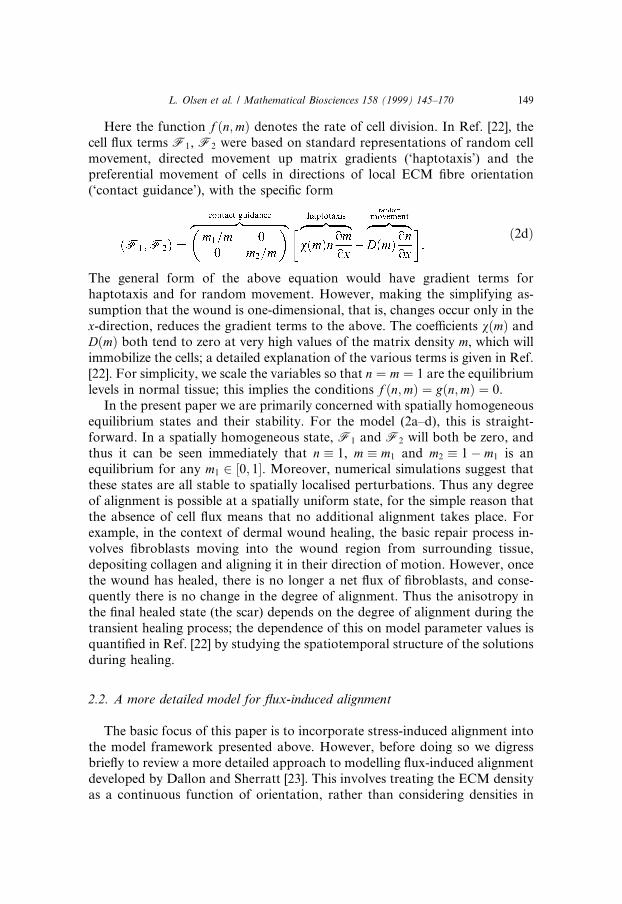
Here the function f �n;m� denotes the rate of cell division. In Ref. [22], thecell ¯ux terms F1, F2 were based on standard representations of random cellmovement, directed movement up matrix gradients (`haptotaxis') and thepreferential movement of cells in directions of local ECM ®bre orientation(`contact guidance'), with the speci®c form
�2d�
The general form of the above equation would have gradient terms forhaptotaxis and for random movement. However, making the simplifying as-sumption that the wound is one-dimensional, that is, changes occur only in thex-direction, reduces the gradient terms to the above. The coe�cients v�m� andD�m� both tend to zero at very high values of the matrix density m, which willimmobilize the cells; a detailed explanation of the various terms is given in Ref.[22]. For simplicity, we scale the variables so that n � m � 1 are the equilibriumlevels in normal tissue; this implies the conditions f �n;m� � g�n;m� � 0.
In the present paper we are primarily concerned with spatially homogeneousequilibrium states and their stability. For the model (2a±d), this is straight-forward. In a spatially homogeneous state, F1 and F2 will both be zero, andthus it can be seen immediately that n � 1, m � m1 and m2 � 1ÿ m1 is anequilibrium for any m1 2 �0; 1�. Moreover, numerical simulations suggest thatthese states are all stable to spatially localised perturbations. Thus any degreeof alignment is possible at a spatially uniform state, for the simple reason thatthe absence of cell ¯ux means that no additional alignment takes place. Forexample, in the context of dermal wound healing, the basic repair process in-volves ®broblasts moving into the wound region from surrounding tissue,depositing collagen and aligning it in their direction of motion. However, oncethe wound has healed, there is no longer a net ¯ux of ®broblasts, and conse-quently there is no change in the degree of alignment. Thus the anisotropy inthe ®nal healed state (the scar) depends on the degree of alignment during thetransient healing process; the dependence of this on model parameter values isquanti®ed in Ref. [22] by studying the spatiotemporal structure of the solutionsduring healing.
2.2. A more detailed model for ¯ux-induced alignment
The basic focus of this paper is to incorporate stress-induced alignment intothe model framework presented above. However, before doing so we digressbrie¯y to review a more detailed approach to modelling ¯ux-induced alignmentdeveloped by Dallon and Sherratt [23]. This involves treating the ECM densityas a continuous function of orientation, rather than considering densities in
L. Olsen et al. / Mathematical Biosciences 158 (1999) 145±170 149
two orthogonal directions, and we discuss it because of the insight given intothe interpretation of the simpler framework.
In Ref. [23], the model variables are N�h; t� and M�h; t�, denoting, respec-tively, cell and ECM densities as a function of time t and orientation h withrespect to an arbitrary reference direction. Spatial variation could be includedin principle, but is omitted in the interests of mathematical simplicity; thus themodel is concerned with spatially homogeneous states, and in particular,spatially homogeneous equilibria and their stability. The conservation equa-tion for cell density N has two terms, representing random reorientation,modelled by angular di�usion, and directed reorientation, representing thetendency of ®broblasts to move preferentially in the direction of ECM orien-tation [34]. This directed reorientation involves a non-local convolution term,since cells and ECM can interact over a range of orientations; this use ofconvolutions is a fundamental feature of a number of models for alignment inother biological systems [16,35]. In the ECM conservation equation, there isonly one term representing the tendency of ®broblasts to reorient collagen intheir direction of motion; again, this involves a convolution. These variousterms again represent the process of ¯ux-induced alignment, although in amore detailed way than the model in Section 2.1.
Details of the mathematical model and its analysis are given in Ref. [23];here, we simply summarise the key results. The basic implication of the modelis that stable equilibria have the form of one or more localised bands of ECMorientations, with no ®bres aligned at intermediate orientations. In particular,the state in which the ECM density is the same at all orientations is unstable,while the state consisting of bands of matrix aligned in two orthogonal di-rections is stable. There is also a wide spectrum of stable anisotropic states,consisting of one or more isolated ECM orientations, with various proportionsof the ECM aligned in these discrete directions. These results are consistentwith those of the simpler model presented in Section 2.1, namely that anydegree of anisotropy is possible as a stable state when ECM is reoriented onlyby cell ¯ux. Moreover, the more detailed framework predicts that these statesconsist of discrete ECM orientations, rather than a continuous range of ®brealignments. This provides speci®c justi®cation for the relevance of the frame-work in Section 2.1, in which only two discrete, orthogonal directions areconsidered. In the remainder of this paper, we use this simpler representationto consider the process of stress-induced alignment, which is more complexmathematically, and thus demands a simple model framework.
3. Basic stress-induced ECM alignment model
The ECM ®bres have the potential to be reoriented by mechanical forceswithin the tissue, as well as by the movement of cells. In this section, we
150 L. Olsen et al. / Mathematical Biosciences 158 (1999) 145±170
consider this `stress-induced alignment' in isolation from ¯ux-induced align-ment; in later sections, we will consider the two mechanisms acting together.Modelling alignment due to mechanical stress is signi®cantly more complexthan for ¯ux-alignment, and we restrict attention simply to the representationof anisotropy via ECM densities in two orthogonal directions, as in Sec-tion 2.1. This is partially justi®ed by the agreement in the ¯ux-alignment casebetween the results predicted by this simple framework, and those of the moredetailed model described in Section 2.2; the essential advantage of the simplerframework is its mathematical tractability.
The key assumptions in our model concern the form of the conversion ratesR1 and R2 between the di�erent matrix alignments: these rates were introducedin Eq. (1). Since we are considering stress-induced alignment, we suppose thatR1 and R2 are functions of the stress tensor r. For simplicity, we restrict at-tention to geometries in which the e�ective principal stress axes are alwaysparallel to the coordinate directions: this includes a number of common woundgeometries, such as a linear (slash) wound and a circular wound. Such casesavoid the need to perform a local diagonalization of r at each point in spaceand time in order to calculate these principal axes, and mean that we can takeR1 and R2 to be simply a function of the diagonal, bulk components of thestress tensor, r11 and r22.
This method of including anisotropy in a mechanical model was used pre-viously in Ref. [13], in a study of actin ®lament alignment. Following theirapproach, we impose the following constraints on the dependence on r of thealignment rates, R1 and R2:· R1 and R2 depend only on the ratio, q � jr11=r22j, of the magnitudes of the
principal stress components;· R1 � ksR�q� and R2 � ksR�1=q�, by symmetry, for some appropriate function
R and (constant) stress-induced alignment rate parameter ks > 0;· R is an increasing function of q, with R�0� � 0 and R is bounded as q!1;
without loss of generality, we set this upper bound to unity.Again following Ref. [13], we take the speci®c form R�q� � qp=�1� qp�. Here,the parameter p > 0 is a measure of the sensitivity of the ECM alignment re-sponse to variations in the stress ®eld.
Thus the conservation equations for m1 and m2 are of the form
om1
ot� ks
qpm2 ÿ m1
qp � 1
� �� g�n;m�; �3a�
om2
ot� ks
m1 ÿ qpm2
qp � 1
� �� g�n;m�; �3b�
where g�n;m� again represents cellular production of new ECM. We begin byconsidering only spatially homogeneous equilibria. In this case there will be noelastic contribution to stress, which will be due entirely to cell traction. This
L. Olsen et al. / Mathematical Biosciences 158 (1999) 145±170 151

results from the pull of cells on local ECM, and its components in the 1- and 2-directions will di�er only in proportion to the amount of ECM aligned in thesedirections. Thus q � r11=r22 � m1=m2.
Again we rescale so that n � m � 1 is the equilibrium level in normal tissue:as in the ¯ux-aligned case, the key issue is the possible values of m1 and m2 �1ÿ m1 at equlibrium. We write / � m1, so that m2 � 1ÿ /, giving
1
ks
d/dt� F �/� � /p�1ÿ /� ÿ �1ÿ /�p/
/p � �1ÿ /�p : �4�Recall that p �> 0� is the alignment response sensitivity parameter. Equilibriaoccur when F �/� � 0, namely for / � 0, 1=2 and 1; / � 0 and 1 correspond,respectively to matrix aligned entirely in the 1- and 2-directions, while / � 1=2corresponds to isotropic matrix (m1 � m2). Stability of these equilibria is easilycalculated from Eq. (4) by considering the qualitative behaviour of F , as shownin Fig. 1. There are two scenarios, depending on the value of p:0
We thus conclude that the fully isotropic con®guration will occur if thesensitivity parameter p is less than the critical (bifurcation) value p � 1, whilethe fully anisotropic con®guration will develop if p is larger than unity.
These results are similar to those of Ref. [13] for spontaneous auto-align-ment of intracellular actin ®laments, and are intuitively plausible: if thealignment response is su�ciently sensitive to changes in the stress ®eld (p > 1)then we expect that the positive feedback that exists between stress anisotropyand matrix alignment will result in maximal alignment. However if the align-
0 < p < 1: / � 0; 1 are unstable, / � 1=2 is globally stable (subject to theconstraint 0 < / < 1).
p > 1: / � 0; 1 are locally stable with basins of attraction �0; 1=2� and�1=2; 1� respectively; / � 1=2 is unstable.
Fig. 1. The qualitative form of the function F �/), de®ned by Eq. (4), for the two cases 0 < p < 1
and p > 1. The circles mark the equilibria / � 0, 1=2 and 1, and arrows indicate the dynamics
towards the locally stable equilibria (®lled circles). When the alignment response is fairly insensitive
to changes in the stress ®eld (p < 1), the isotropic con®guration (/ � 1=2) is stable, but when the
alignment response is stronger (p > 1), fully aligned states (/ � 0; 1) become stable.
152 L. Olsen et al. / Mathematical Biosciences 158 (1999) 145±170

ment response is su�ciently insensitive, then the generation of stress in thedominant direction of alignment may be insu�cient to overcome the intrinsicequilibrating mechanism whereby m1 is converted into m2 at a rate propor-tional to m1, and vice versa ± see Eqs. (3a) and (3b).
The isotropic architecture of normal skin corresponds to / � 1=2 and isclearly stable to small perturbations. Thus we require 0 < p < 1 in order thatthe model be realistic. However, a number of other tissues are highly aniso-tropic, in particular the scar tissue that results from dermal wound healing.This represents a stable, partially aligned state, corresponding to 1=2 < / < 1,which is clearly inconsistent with the above model. In the remainder of thispaper, we discuss various extensions of the model, with the aim of resolvingthis discrepancy. In Section 4, we consider the combined action of ¯ux- andstress-induced alignment; this combination of the models in the current sec-tion and Section 2.1 is more realistic than either model considered in isola-tion, but in fact does not resolve the discrepancy. In Section 5, we study afurther extension of the model, in which there are two types of interactingECM, and show that this extension can give stable, partially aligned equi-libria.
4. Combining ¯ux- and stress-induced alignment
A natural extension of the models we have presented is to consider the ef-fects of ¯ux- and stress-induced alignment acting together. In fact the steadystate structure in this case is determined only by the stress component of thealignment. This is for the simple reason that the cell ¯ux is necessarily zero at aspatially homogeneous equilibrium. Of course, the inclusion of ¯ux-inducedalignment does alter the approach of the system towards equilibrium. To il-lustrate this, we digress from the consideration of homogeneous equilibria, andconsider the way in which the two alignment mechanisms interact during nu-merical simulations of the wound healing process.
For simplicity, we restrict attention to the case of one space dimension,corresponding to a linear (`slash') wound. In this case the equations governingECM orientation, incorporating both stress- and ¯ux-alignment, have theform
�5a�
�5b�
L. Olsen et al. / Mathematical Biosciences 158 (1999) 145±170 153

where the principal stress components are
and the cell ¯ux is given by
�5c�
Here, u is the displacement of a material point originally at a position x,E1 � E=�1� m�;E2 � m=�1ÿ 2m�, where E is Young's modulus and m is thePoisson ratio, l1 and l2 are the shear and bulk viscosities, respectively, ands�n;m� is the tractional stress exerted by the cells. Thus, we are considering thematrix to be a linear viscoelastic material which contains cells as contractileunits (see Ref. [1]). We take s�n;m� to be proportional to cell and matrixdensities when these are low, but with a decrease to zero at high densities,re¯ecting the phenomenon of traction inhibition [36,2]. The above is simply acombination of Eqs. (2a), (2b), (3a), (3b); the viscoelastic terms must be in-cluded in the stress tensor since we are considering the non-equilibrium situ-ation. These equations are coupled to the conservation Eq. (2c) for cell density,which in one space dimension has the form
onot� oF1
ox� f �n;m� �6�
and to the force balance equation
or11
ox� smu and
or22
ox� 0: �7�
The latter assumes that the system is operating at very low Reynolds number sothat inertial terms can be ignored. Hence, the viscoelastic forces within the cell-matrix milieu are in balance with external body forces. We assume that thelatter are due to elastic tethering and take the form smu, where s is the modulusof elasticity, and u � �u; 0� is the displacement vector. We solve these equationson 0 < x < L1, with x � 0 representing the centre of a symmetric wound, andthe wound edge at x � L� L1. We use symmetry boundary conditions atx � 0, and ®x the variables at their unwounded levels at x � L1, i.e.m1 � m2 � 1=2, n � 1, u � 0. To simulate a wound, we take n � 0, m1 � m2 �minit initially inside the wound (0 < x < L), with unwounded levels elsewhere;
154 L. Olsen et al. / Mathematical Biosciences 158 (1999) 145±170

here minit < 1 represents a low density of the ECM deposited during the initialin¯ammatory response to injury.
Fig. 2 illustrates the solutions of Eqs. (5a)±(5c), (6) and (7), subject to theseend conditions, for a set of parameters corresponding to stress-inducedalignment only (kf � 0). Cells (n) move towards the wound centre as expected,depositing ECM (m) in the wave-back. The cell- and ECM-mediated traction
Fig. 2. Numerical simulation of dermal wound healing in the case of stress-induced alignment only,
using Eqs. (5a)±(5c), (6) and (7) with kf � 0, ks 6� 0. We plot pro®les of cell density (n), tissue
displacement (u), the di�erence m1 ÿ m2 of the orthogonal ECM density components and the stress
ratio q � r11=r22 at time t � 5. The solution has the form of wave-like solutions (direction indicated
by the arrows), with cells and ECM moving into the wound from its periphery. Behind this wave
front, the system evolves towards the uniform, dermal steady state n � 1, m1 � m2 � 12
and u � 0,
representing normal healing with no permanent ECM alignment. The functional forms and pa-
rameter values are: s�n;m� � s0nm=��j2sn� n2��j2
sm� m2��, f �n;m� � n�ÿn� a0m=�j2
a � m2��,g�n;m� � �1ÿ m�n, D�m� � D0m=�j2
D � m2�, v�m� � 0, D0 � 0:2, jD � 0:5, a0 � 1:01, ja � 0:1,
E1 � 2, E2 � 2, l1 � 1, l2 � 1, s0 � 1, jsn � 0:5, jsm � 0:05, s � 50, p � 0:5, ks � 10 and
minit � 0:1. The initial conditions are n�x; 0� � �x=10�h=�1� �x=10�h�, m�x; 0� � minit��1ÿ minit��x=10�h=�1� �x=10�h�, m1�x; 0� � m2�x; 0� � m�x; 0�=2 and u�x; 0� � 0, with h � 50. The
boundary conditions are given by symmetry at x � 0 and normal dermal values for the variables as
x!1, which we approximate using the in®nite domain approximation x1 � 15. Only the pro®les
in the region 06 x6 10 are shown, for clarity. The equations were solved numerically using an
alternating direction semi-implicit ®nite di�erence scheme, with mesh sizes are Dx � 0:05 and
Dt � 0:001.
L. Olsen et al. / Mathematical Biosciences 158 (1999) 145±170 155

forces, together with the viscoelastic response of the ECM, cause a net stress(r11) and thus a tissue displacement (u). Ahead of the wave-front, the positivetraction gradient gives rise to the positive displacement (u > 0): this gradient isdue to the increased traction forces generated in the wave itself compared withthe relatively acellular tissue ahead of the wave. Similarly, behind the wave,traction is inhibited by the high ECM density (in particular), resulting in anegative traction gradient and hence, negative displacement (u < 0). The dis-placement is proportional to the stress gradient by virtue of the force-balanceEq. (7). Fig. 2 shows that m1 > m2 if and only if r1 > r2, or q > 1. The mag-nitude of m1 ÿ m2 generally increases with the (stress-induced) alignment rateparameter ks, although the e�ect is self-limiting due to the negative feedbackproperty of stress-alignment which occurs whenever p < 1, a process whichaccelerates with increasing ks.
In order to explain the pro®le of m1 ÿ m2 in Fig. 2, we consider the roles ofthe mechanical stress terms as detailed in Fig. 3. In the wave-front there is a
Fig. 3. Illustration of the tissue stresses implied by the numerical solutions illustrated in Fig. 2. We
show pro®les of the cell traction stresses (top left), ECM viscoelastic stresses (top right) and total
stresses (bottom left) at time t � 5. The x-axis is expanded for clarity. Components of these stress
terms in the 1- and 2-directions, r11 and r22, are indicated by dashed and dotted curves, respec-
tively. Also shown (bottom right) is the stress ratio, q � jr11=r22j, as in Fig. 2 (bottom-right). Note
the sharp cell traction stress within the region 4 < x < 5 which contains the position of the ad-
vancing cell front at time t � 5 (see also Fig. 2).
156 L. Olsen et al. / Mathematical Biosciences 158 (1999) 145±170
pronounced, positive cell traction pro®le (Fig. 3: top-left), eliciting a coun-teracting (negative) viscoelastic ECM response by virtue of Eq. (7). This in-trinsic response is greater in the 1-direction than in the 2-direction since thedilational (bulk) stress acts in both directions whereas the shear stress acts onlyin the 1-direction (Fig. 3: top-right). Consequently, near the peak of thetraction pro®le, the cell traction stress dominates the ECM stress to a greaterextent in the 2-direction than in the 1-direction, causing a greater net stress inthis direction (Fig. 3: bottom-left). Therefore, the ratio of absolute stresses inthe 1-direction to the 2-direction is less than one in this region (Fig. 3: bottom-right), thus promoting the conversion of m1 into m2 in this region, by Eqs. (5a)and (5b).
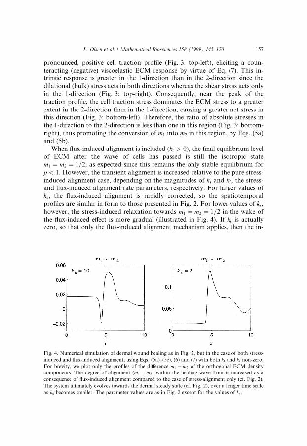
When ¯ux-induced alignment is included (kf > 0), the ®nal equilibrium levelof ECM after the wave of cells has passed is still the isotropic statem1 � m2 � 1=2, as expected since this remains the only stable equilibrium forp < 1. However, the transient alignment is increased relative to the pure stress-induced alignment case, depending on the magnitudes of ks and kf , the stress-and ¯ux-induced alignment rate parameters, respectively. For larger values ofks, the ¯ux-induced alignment is rapidly corrected, so the spatiotemporalpro®les are similar in form to those presented in Fig. 2. For lower values of ks,however, the stress-induced relaxation towards m1 � m2 � 1=2 in the wake ofthe ¯ux-induced e�ect is more gradual (illustrated in Fig. 4). If ks is actuallyzero, so that only the ¯ux-induced alignment mechanism applies, then the in-
Fig. 4. Numerical simulation of dermal wound healing as in Fig. 2, but in the case of both stress-
induced and ¯ux-induced alignment, using Eqs. (5a)±(5c), (6) and (7) with both kf and ks non-zero.
For brevity, we plot only the pro®les of the di�erence m1 ÿ m2 of the orthogonal ECM density
components. The degree of alignment (m1 ÿ m2) within the healing wave-front is increased as a
consequence of ¯ux-induced alignment compared to the case of stress-alignment only (cf. Fig. 2).
The system ultimately evolves towards the dermal steady state (cf. Fig. 2), over a longer time scale
as ks becomes smaller. The parameter values are as in Fig. 2 except for the values of ks.
L. Olsen et al. / Mathematical Biosciences 158 (1999) 145±170 157

coming wave of cells leaves permanently aligned ECM behind it, with thedegree of alignment dependent on details of the wave form: this dependence isexplored in detail in Ref. [22].
5. Model extension: the two ECM types
For the combination of stress- and ¯ux-induced alignments, only fullyaligned or isotropic equilibria are stable, a property that is incompatible withthe wide range of partially aligned equilibria observed in real tissues. In thissection, we consider a possible resolution of this discrepancy, namely that twodi�erent ECM components may be interacting, with di�erent alignmentproperties. This is particularly relevant to the proliferative phase of woundhealing, during which both a collagen and a ®bronectin-coated ®brin networkare present in signi®cant quantities, with ®broblasts able to realign both ECMtypes in vitro [37,38]. We consider ®rst (Section 5.1) the case in which bothmatrix types are subject to both stress- and ¯ux-alignment, showing thatpartially aligned states can then be stable. In Section 5.2 we then suppose thatonly one matrix type is subject to both alignment mechanisms, with the otheronly ¯ux-aligned, showing that the stability of partially aligned states for twomatrix types is a robust result, applying to this case also. The alternativepossibility that only ¯ux-induced alignment applies for both matrix types istrivial, with any degree of alignment possible at equilibrium.
5.1. The two ECM types, both stress- and ¯ux-aligned
We denote by m�1� and m�2� the densities of the two di�erent types of ECM;again, the subscripts 1 and 2 denote components in the two orthogonal direc-tions, and suppose that the orthogonal components of m�1� and m�2� contributelinearly (additively) to the cell-derived traction stress tensor. At the dermalequilibrium where n � 1, m�1� � 1, m�2� � 1 and u � 0, we de®ne / � m�1�1 andw � m�2�1 . The cell traction function, s will now be a function of three variablesnamely, n;m�1� and m�2�. The net stress components are then given by
r11 � /s�1��1; 1; 1� � ws�2��1; 1; 1� and
r22 � �1ÿ /�s�1��1; 1; 1� � �1ÿ w�s�2��1; 1; 1�
which yields the stress ratio
q � r11
r22
� /� cw1ÿ /� c�1ÿ w� ;
where
158 L. Olsen et al. / Mathematical Biosciences 158 (1999) 145±170

c � s�2��1; 1; 1�s�1��1; 1; 1� :
We denote the alignment sensitivity parameters for m�1� and m�2� by p and q,respectively. Then, as before, we obtain di�erential equations for perturbationsin / and w about the dermal equilibrium:
1
k�1�s
d/dt� F �/;w� � �/� cw�p�1ÿ /� ÿ �1ÿ /� c�1ÿ w��p/
�/� cw�p � �1ÿ /� c�1ÿ w��p ; �8a�
1
k�2�s
dwdt� G�/;w� � �/� cw�q�1ÿ w� ÿ �1ÿ /� c�1ÿ w��qw
�/� cw�q � �1ÿ /� c�1ÿ w��q : �8b�
We can extend the analysis of Section 3 to this system; the details are similarand we omit them for brevity. The analysis implies that at equilibria
/ � 1
"� 1ÿ w
w
� �p=q#ÿ1
:
Therefore, 0 < / < 1=2 if and only if 0 < w < 1=2, and 1=2 < / < 1 if andonly if 1=2 < w < 1. Also, / or w are only 0, 1=2 or 1 when / � w; thus onematrix type can only be isotropic/fully aligned if the other matrix type also hasthis alignment. Standard local stability analysis shows that· �0; 0� and �1; 1� are locally stable if and only if p > 1 and q > 1.· �1=2; 1=2� is locally stable if and only if p � cq < 1� c.These results are illustrated in Fig. 5.
Using phase plane analysis we can obtain results on the global stability ofthese equilibria. This shows that if both the ECM types are su�ciently sensitiveto variations in the local stress ®eld, that is p > 1 and q > 1, then both m�1� andm�2� become fully aligned in the same direction. Conversely, if both the ECMtypes are relatively insensitive to the stress ®eld, so that p � cq < 1� c, then thefully isotropic, or `random' con®guration arises. This includes the possibilitythat either p > 1 or q > 1 (but not both), so that the isotropic con®gurationpossesses a wider attracting domain in the bifurcation plane than in theanalogous model with one ECM type, where this equilibrium is (globally)stable if and only if p < 1.
The `intermediate' situation, in which one ECM type is insensitive to thelocal stress ®eld and the other is su�ciently sensitive results in a partiallyaligned con®guration. For example, suppose that m�1� is insensitive to aniso-tropic stress and that m�2� is su�ciently sensitive, so that p < 1 andq > �1� cÿ p�=c: then (locally) stable equilibria �m�1�;m�2�� � �/�;w�� and�1ÿ /�; 1ÿ w�� occur where 0 < w� < /� < 1=2, indicating that m�1� is alignedto a lesser extent than m�2�.
L. Olsen et al. / Mathematical Biosciences 158 (1999) 145±170 159

5.2. Two ECM types, one only ¯ux-aligned
We now consider the possibility that two matrix types interact, but with onlyone subject to stress-induced alignment, with the other aligned only by cell ¯ux.The object of this extension is to consider the robustness of the potential sta-bility of partially aligned equilibria. We suppose that the orthogonal compo-nents of m�1� and m�2� contribute linearly (additively) to the cell-derived tractionstress tensor, as in the previous model. However, in this case, the componentsof net stress feed back only into the rate of conversion of the orthogonalcomponents of m�1�, with m�2� subject only to ¯ux-induced alignment (previ-ously, both of the ECM types were stress-aligned as well as ¯ux-aligned).
We suppose that the traction stresses are given by
rii � m�1�i
m�1�s�1� n;m�1�;m�2�ÿ �� m�2�i
m�2�s�2� n;m�1�;m�2�ÿ �
for i � 1; 2 with s�1�, s�2�P 0. We also assume that only m�1� is stress-aligned viathe mechanism discussed in Section 3, that both types may be ¯ux-aligned andthat the dermal equilibrium density of each ECM type has been scaled to unity.At this equilibrium (where cell density n � 1 and there in no net tissue dis-placement), the stress ratio is given by
q � r11
r22
� c1 � /c2 � 1ÿ /
;
Fig. 5. An illustration of the regions in p±q space in which the steady states �/;w� � �0; 0�,�1=2; 1=2� or �1; 1� are (locally) stable. The shaded regions indicate where all three equilibria are
unstable; in these regions, detailed phase plane analysis reveals the existence of at least one locally
stable equilibrium in the region 0 < /;w < 1=2, with a corresponding equilibrium in
1=2 < /;w < 1.
160 L. Olsen et al. / Mathematical Biosciences 158 (1999) 145±170

where
c1 �s�2��1; 1; 1�m�2�1
s�1��1; 1; 1� and c2 �s�2��1; 1; 1�m�2�2
s�1��1; 1; 1� �s�2��1; 1; 1� 1ÿ m�2�1
� �s�1��1; 1; 1�
and / is the equilibrium value of m�1�1 . Since matrix of type 2 is only ¯ux-aligned, m�2�1 can take any value (subject to 0 < m�2�1 ) at equilibrium. There-fore, c1 and c2 may be regarded as parameters, and we investigate the rangeof possible values for / and the stability of these equilibria, as c1, c2 and pvary.
To begin, we use the above formulae to derive the di�erential equationgoverning (temporal) perturbations in / about the dermal equilibrium, giving
1
ks
d/dt� F �/; c1; c2; p� �
�c1 � /�p�1ÿ /� ÿ �c2 � 1ÿ /�p/�c1 � /�p � �c2 � 1ÿ /�p : �9�
Note that the denominator is positive since the parameters c1, c2 and p are non-negative and 06/6 1, and that the function F �/� is continuous on this in-terval. Also, F �0�P 0 and F �1�6 0, with equality if and only if c1 � 0 andc2 � 0, respectively. This implies the existence of at least one locally stableequilibrium in the con®ned set 0 < / < 1 for the case c1, c2 > 0, and that anodd number of equilibria exist in this interval.
Detailed investigation of equilibria requires care. In particular, the numberof equilibria depends on parameter values. The boundaries in parameter spacebetween di�erent numbers of equilibria will correspond to repeated steady statesolutions of (9), and solving F � dF =d/ � 0 gives a family of curves in the�c1; c2� plane, expressed parametrically in terms of / in the following form:
c1 � C1�/; p� � p/�1ÿ /� 1
"� 1ÿ /
/
� �1=p#ÿ 1� /; �10a�
c2 � C2�/; p� � p/�1ÿ /� 1
"� /
1ÿ /
� �1=p#ÿ /: �10b�
When p < 1, a straightforward check con®rms that C1 and C2 are never bothpositive, so that there are no changes in the number of equilibria. Moreover,when p� 1, F �/� � 1=2ÿ /, so that / � 1=2 is the unique equilibrium. Thusfor any p < 1, there is a unique equilibrium, which is globally stable. Thisequilibrium varies monotonically from 1=2 to c1=�c1 � c2� � m�2�1 as p increasesfrom 0 to 1. This is as expected intuitively, since p measures the sensitivity ofm�1� alignment to anisotropy in the stress ®eld. Thus when p� 1, changes instress have relatively little e�ect. As p increases, m�1� becomes aligned sympa-thetically to the alignment of m�2�, with the alignments becoming the same atp � 1; recall that m�2� is ¯ux-aligned only, with m�1� subject to both alignmentmechanisms.
L. Olsen et al. / Mathematical Biosciences 158 (1999) 145±170 161

As p increases above 1, multiple equilibria are possible, depending on thevalues of c1 and c2. When these parameters are su�ciently large, there is asingle equilibrium, with the value of / re¯ecting sympathetic alignment of m�1�
and m�2�. However, when p > 1, the curve de®ned by (10) now lies in thepositive quadrant of the c1±c2 plane; the form of this curve is illustrated inFig. 6, showing in particular the cusp at c1 � c2 � �p ÿ 1�=2. This point cor-responds to / � 1=2, and a cusp, or fold, bifurcation occurs there. For c1 andc2 lying below this critical point there are three possible equilibrium values of/ 2 �0; 1�: two are locally stable and their basins of attraction are separated bythe third, unstable equilibrium. That the bifurcation is from one to three(rather than > 3) equilibria can be shown by continuity, with reference to thespecial case p!1. In this limit the bifurcation curve (10) approaches the twoparallel lines c2 � c1 � 1, and determination of the limiting form of F showsthat there are three equilibria for c1, c2 between these lines, namely 0, 1 and�1ÿ c1 � c2�=2. For c1, c2 above/below both of these lines, / � 0=1 is the onlyequilibrium. Thus as p !1, only fully aligned states are stable; this is ex-pected intuitively, since large p corresponds to strong sensitivity to anisotropyin the stress ®eld.
Fig. 6. Plots of the parametric curves de®ned (in the positive quadrant) by c1�/; p� and c2�/; p�, for
p � 2, 4, 6, 8 and 10 (increasingly broken curves), delineating the regions in which there exist one
(to the top-right of the curves) and three (to the bottom-left of the curves) equilibria in the interval
0 < / < 1. We use logarithmic axes, for clarity. The cusp bifurcations at c1 � c2 � �p ÿ 1�=2 are
apparent from these curves.
162 L. Olsen et al. / Mathematical Biosciences 158 (1999) 145±170

Variant: non-linear traction coupling: We brie¯y consider a di�erent sce-nario in which the components of the two ECM types contribute multipli-catively rather than additively (or linearly) to the traction stress. In thecontext of wound healing, this is partly motivated by the co-distribution of®bronectin and collagen ®bres in wound tissue [39,40]. It is believed thatadhesion complexes involving collinear extracellular ®bronectin and collagen®brils at cell surfaces may coordinate the intracellular and extracellular me-chanical responses which result in macroscopic cell-derived traction forces[41,42,37,43].
Such observations suggest the hypothesis that both collagen and ®bronectinmust be aligned (to some extent) in a given direction for cells to exert tractionforces in that direction. In this scenario, the simplest expression for the tractionstress components is a multiplicative coupling of the components of the twoECM types, given by
rii � m�1�i
m�1�m�2�i
m�2�s n;m�1�;m�2�ÿ �
for i � 1; 2 (and sP 0). The stress ratio, previously given by Eq. (21), nowbecomes
q � /m�2�1
�1ÿ /�m�2�2
:
Determination of steady states and their stability is straightforward; we omitthe details for brevity and simply summarise the results. When p > 1, the fullyaligned equilibria / � 0; 1 are both stable, separated by a third unstableequilibrium. Conversely, for p < 1, it is this intermediate state that is stable,and with a preferential alignment for m�1� mirroring that for m�2�; as p ! 0,/! 1=2, corresponding to an isotropic state.
5.3. Conclusions
We have shown that the interaction between cells and two types of ECMenables a partially aligned state to be a stable equilibrium in the presence ofstress-induced alignment. This is true whether one or both of the matrix typesis aligned by the stress ®eld, although in the latter case, the alignment prop-erties of the two matrix types must be signi®cantly di�erent. This suggests thatwhere partial ECM anisotropy is observed, two ECM components with dif-ferent alignment properties must be present and interacting. In the context ofdermal wound healing, it is well known that collagen and ®bronectin-coated®brin matrices act in combination throughout the healing process; our mod-elling predicts that di�erences in the alignment properties of these matrixcomponents may be crucial in establishing the alignment patterns that areobserved in scar tissue. Even in the case of two ECM types, one feature not
L. Olsen et al. / Mathematical Biosciences 158 (1999) 145±170 163

exhibited by the model is the coexistence of stable partially aligned and iso-tropic states. For wound healing, this is a signi®cant omission, since alignedscar tissue coexists with isotropic surrounding dermis. The model thus suggeststhat this inconsistency with experimental observations re¯ects di�erent align-ment properties in the two tissues.
6. Alignment at the microscopic scale
The models considered so far have all involved continuum representationsof cell and matrix density. In this section, we discuss a discrete model foralignment, whose aim is to address the possibility of alignment on a smallerscale. Although many connective tissues are spatially homogeneous and iso-tropic at a macroscopic level, they nevertheless have spatial structure and lo-calised anisotropy at the microscopic level. Our objective in this section is toshow that a di�erent type of mathematical model can reveal this local structure,which is entirely masked by continuum models. We restrict attention to ¯ux-induced alignment; the e�ect of anisotropic stress at this smaller scale is animportant but challenging question that we hope to consider in subsequentwork. In this new model, spatial variation is a key ingredient. However, wemust emphasise that the spatial scale here is much smaller than in the previousmodel frameworks, and that the size of domain we consider (1 mm2) would beaveraged to a single point in the continuum models described above. Forsimplicity, we restrict attention to two spatial dimensions: this has the greatadvantage that orientations can be expressed as a single real number. In thistwo-dimensional domain, we represent cells as discrete objects, while ECM istreated as a continuous variable. We make the simplifying assumption thatECM density does not vary with position, and include variation only in theorientation of the matrix. Thus the model variables are the positions P i�t�(16 i6K) of the K cells, their directions of motion Di�t� (16 i6K), and theECM orientation H�x; t�; Di and H are angles measured with respect to thesame reference direction, and to be speci®c, we take this to be the x-coordinatedirection in our two-dimensional domain. Note that we assume a singledominant orientation for the matrix at each space point; this is a reasonableassumption at this smaller spatial scale.
Within this framework, ¯ux-induced alignment is represented very simply,as a change in H towards the directions Di of cells near that point in space. Thisreorientation will in fact involve a time lag, because the time taken for ECMreorientation corresponds to the cell moving a distance that is signi®cant on thesmall scale we are considering. In practice, ®broblasts have signi®cantlyelongated shapes, with direction determined at the front of the cell while re-modelling occurs at the rear [44]; the time lag gives a measure of this elonga-tion. This gives an equation for H of the form
164 L. Olsen et al. / Mathematical Biosciences 158 (1999) 145±170

oH�x; t�ot
� jXK
i�1
W P i�t�� ÿ x�W Di�t� ÿ tlag� ÿH�x; t��; �11a�
where tlag is the time lag, which we assume to be constant. Here we assume alinear superposition of cell activity. This simplifying assumption is realisticprovided cell densities are relatively low; at very high cell densities, newphenomena arise via direct cell±cell interactions, which require a quite dif-ferent type of model formulation [35,17]. The function W is a weightingfunction that decreases with the distance between the cell and the space pointconcerned; we take W to be zero at distances greater than about 10lm (aboutone cell length), so that only cells within this distance of a point can in¯uencethe ECM alignment there. The function W is linear when Di � H, but on alarger scale W is periodic, re¯ecting the fact that cell i is aligned with the localECM whenever Di and H di�er by a multiple of p. The parameter j re¯ectsthe extent of cellular reorientation of matrix, and is the key parameter of themodel.
Cell position changes simply because of cells moving in their current di-rection; we take cell speed to be a constant S, so that
dP i
dt� S�cos Di; sin Di� �16 i6K�: �11b�
The direction of the cells will also change of course, because of their tendencyto move up ECM ®bres. We model this `contact guidance' by assuming thatcell direction aligns exactly with the ECM orientation; thus we take
Di�t� � H P i�t�; t� � �16 i6K�: �11c�This equation for Di completes the formulation of the model; further detailswill be presented elsewhere [45]. From Eq. (11c), it is clear that the time lag tlag
plays an important role in the model; in particular, if tlag � 0, the cells orientthe ECM towards the current cell orientation, which is simply that of theECM, resulting in no restructuring of the matrix. At non-zero tlag, however, thealignment of the matrix is signi®cant. A natural extension of the model wouldbe to incorporate some persistence into the ®broblast movement, replacingEq. (11c) with a di�erential equation in which dDi=dt is related to�H�Pi; t� ÿ Di�; in fact we have found that such extensions do not alter thequalitative nature of the results. Further details of numerical methods for thistype of model are given in Ref. [46].
We solve Eqs. (11a)±(11c) numerically on a square domain; to representspatial homogeneity, we use periodic boundary conditions. Numerically, thereis a ®xed space grid for the ECM, but the cells are allowed to take any posi-tions, rather than being con®ned to grid points. Eq. (11c) then requires thevalue of ECM orientation H between grid points, and we determine this using atensor product interpolant with quartic Lagrangian interpolation in each
L. Olsen et al. / Mathematical Biosciences 158 (1999) 145±170 165
direction [47]. We take the matrix to be isotropic with two orthogonal orien-tations initially, re¯ected in numerical simulations by randomly choosing theinitial value of H at each point in the spatial grid to be one of the two direc-tions. The cells are initially placed uniformly in the domain.
Fig. 7 illustrates a range of solutions of Eqs. (11a)±(11c), solved numericallyin this way, using 196 cells in a domain of size 1 mm� 1 mm. We illustrate thematrix orientations by plotting a series of short curve segments with tangentswhose angle is equal to the matrix alignment H at each point; in the languageof ¯uid dynamics, these curve segments are streamlines. The most signi®cantaspect of this alignment pattern is the variation with j, which measures theextent to which the ECM is reoriented by the cells. When j is low, the matrixremains in a disorganised state, similar to the initial random state; this is ex-actly as expected, since at low j the cells have little e�ect on the matrix throughwhich they are moving. As j is increased, patterns of alignment develop. Thewhole domain does not become aligned, however; rather, a series of smallregions of roughly unidirectional alignment develop, on a length scale whichincreases as j increases approaching a value of about 250 lm.
7. Discussion
In this paper we have presented a number of ways to model cell±matrixanisotropic interactions. The main body of the paper deals with a continuum-type model which considers alignment on a macroscopic scale. In Section 6 weconsider a novel discrete model on the microscopic scale. The simulations ofthis model show that the alignment patterns predicted by the macroscopicmodels discussed in previous sections of the paper can in fact mask a pattern ofmicroscopic alignment, occuring on a scale of a few cell lengths. The occur-rence of such patterns depends on the strength of the ¯ux-induced alignment,requiring that the matrix orientation is su�ciently sensitive to cell movements.These microscopic alignment patterns will be superimposed on the macro-scopic patterns described in previous sections of the paper, and may play animportant role in the properties of the tissue. Important challenges raised bythese results include the incorporation of stress into this microscopic model,and the extension of a model re¯ecting this microscopic detail to a macroscopicscale; this latter problem is straightforward in principle, but leads to an un-feasible computational problem. Furthermore, cell motion arises as a result ofthe mechanical interaction between cells and matrix, which is mediatedthrough cell traction. Therefore, from a detailed mathematical description ofthis interaction, one should be able to recover the ¯ux term. At the moment,such a detailed description does not exist, but its derivation would have ap-plication in many areas of mathematical biology in which cell motion is im-portant.
166 L. Olsen et al. / Mathematical Biosciences 158 (1999) 145±170

Fig. 7. The ECM orientation is shown for the discrete cell model with various values of j. In the top
left j � 0, so that the initial con®guration of the ECM is preserved; in the top right j � 2, in the
bottom left j � 5 and in the bottom right j � 10. As j increase the regions of alignment become
larger. The cell speed is 40 l/h, W�h� � sinh and W �Pi ÿ x� � axay with ax � maxf�1ÿ jpx ÿ xj=L�; 0gand ay � maxf�1ÿ jpy ÿ yj=L�; 0gwhere P i � �px; py�, x � �x; y� and L is a typical cell diameter, taken
to be 10 lm. There are 101 grid points in each direction and the time step and tlag are both 0:15h. The
®gure shows solutions after a long time (1000 h), allowing transients to dissipate. It is important to
stress that the ®gure does not show permanent equilibria, since the solutions continue to change
dynamically as the cells move through the domain. As time progresses, e�ects from the periodic
boundary conditions will dominate the solution; however, by changing the boundary conditions to
no ¯ux where the cells are randomly allowed to re-enter the domain when they leave, the same
qualitative features of the solution appear and persist. By examining both boundary conditions, it can
be seen that the structure is not introduced by the randomness in the no ¯ux boundary conditions and
gives con®dence that this structure would be present for simulations with an in®nite domain. If the
initial conditions are altered such that the ECM orientation is random, the same features are present.
L. Olsen et al. / Mathematical Biosciences 158 (1999) 145±170 167

For the models on the macroscopic scale, we have considered two di�erentmatrix components and assumed that their re-alignment depends only on cell±matrix interactions. In reality, the matrix networks will interact with each otherso that a more realistic model should consider how the reorientation of onematrix component a�ects other matrix components.
Acknowledgements
L.O. would like to thank the EPSRC for an Earmarked Studentship inMathematical Biology. This work was supported by grant GR/K71394 fromthe EPSRC, and by a grant from the London Mathematical Society (scheme 3).We thank Professor Mark Ferguson (University of Manchester) for helpfuldiscussions.
References
[1] J.D. Murray, G.F. Oster, Cell traction models for generating pattern and form in
morphogenesis, J. Math. Biol. 19 (1984) 265.
[2] J.D. Murray, P.K. Maini, R.T. Tranquillo, Mechanochemical models for generating
biological pattern and form in development, Phys. Rep. 171 (1988) 59.
[3] M.E. Orme, M.A.J. Chaplain, A mathematical model of the ®rst steps of tumour-related
angiogenesis: capillary sprout formation and secondary branching, IMA J. Math. Appl. Med.
Biol. 13 (1996) 73.
[4] A.J. Perumpanani, J.A. Sherratt, J. Norbury, Mathematical modelling of capsule formation
and multinodularity in benign tumour growth, Nonlinearity 10 (1997) 1599.
[5] P. Tracqui, D.E. Woodward, G.C. Cruywagen, J. Cook, J.D. Murray, A mechanical model
for ®broblast-driven wound healing, J. Biol. Systems 3 (1995) 1075.
[6] A.J. Perumpanani, J.A. Sherratt, J. Norbury, H.M. Byrne, Biological inferences from a
mathematical model for malignantinvasion, Invasion Metastasis 16 (1996) 209.
[7] R.B. Dickinson, R.T. Tranquillo, A stochastic model for adhesion-mediated cell random
motilityand haptokinesis, J. Math. Biol. 31 (1993) 563.
[8] V.H. Barocas, A.G. Moon, R.T. Tranquillo, The ®broblast-populated collagen microsphere
assay of celltraction force ± part 2: Measurement of the cell traction parameter, J. Biomech.
Eng. 117 (1995) 161.
[9] I. Ferrenq, L. Tranqui, B. Vailhe, P.Y. Gumery, P. Tracqui, Modelling biological gel
contraction by cells: Mechanocellular formulation and cell traction force quanti®cation, Acta
Biotheoret. 45 (1997) 267.
[10] V.H. Barocas, R.T. Tranquillo, An anisotropic biphasic theory of tissue-equivalent mechan-
ics: The interplay among cell traction ®brillar network deformation ®bril alignment and cell
contact guidance, J. Biomech. Eng. Trans. ASME 119 (1997) 137.
[11] S. Veronese, H. Othmer, A computational study of wave propagation in a model for
anisotropic cardiac ventricular tissue, Lect. Notes Comp. Sci. 919 (1995) 248.
[12] A.T. Winfree, Heart muscle as a reaction±di�usion medium: The roles of electric potential
di�usion activation front curvature and anisotropy, Int. J. Bifurc. Chaos 7 (1997) 487.
168 L. Olsen et al. / Mathematical Biosciences 158 (1999) 145±170

[13] J.A. Sherratt, J. Lewis, Stress-induced alignment of actin ®laments and the mechanicsof
cytogel, Bull. Math. Biol. 55 (1993) 637.
[14] G. Civelekoglu, L. Edelstein-Keshet, Modelling the dynamics of F-actin in the cell, Bull.
Math. Biol. 56 (1994) 587.
[15] A. Suciu, G. Civelekoglu, Y. Tardy, J.J. Meister, Model for the alignment of actin ®laments in
endothelial cells subjected to ¯uid shear stress, Bull. Math. Biol. 59 (1997) 1029.
[16] G.B. Ermentrout, L. Edelstein-Keshet, Models for contact-mediated pattern formation: cells
that form parallel arrays, J. Math. Biol. 29 (1990) 33.
[17] A. Mogilner, L. Edelstein-Keshet, Spatio-angular order in populations of self-aligning objects:
formation of oriented patches, Physica D 89 (1996) 346.
[18] A. Stevens, Trail following and aggregation of myxobacteria, J. Biol. Sys. 3 (1995) 1059.
[19] A. Deutsch, Towards analysing complex swarming patterns in biological systems with the help
of lattice-gas cellular automata, J. Biol. Sys. 3 (1995) 947.
[20] J. Cook, Waves of alignment in populations of interacting oriented individuals, Forma 10
(1995) 171.
[21] D. Gr�ubaum. Advection-di�usion equations for generalised tactic searching behaviors. J.
Math. Biol. (in press).
[22] L. Olsen, P.K. Maini, J.A. Sherratt, B. Marchant. Simple modelling of extracellular matrix
alignment in dermal wound healing. i. Cell ¯ux induced alignment. J. Theor. Med. 1 (1998)
175.
[23] J.C. Dallon, J.A. Sherratt. A mathematical model for ®broblast and collagen orientation. Bull.
Math. Biol. (in press).
[24] G.J. Pettet, H.M. Byrne, D.L.S. McElwain, J. Norbury. A model of wound-healing
angiogenesis in soft tissue. Math. Biosci. (in press).
[25] M.A.J. Chaplain, H.M. Byrne, Mathematical modelling of wound healing and tumour growth
± 2 sides of the same coin, Wounds: A Compendium of Clinical Research and Practice 8 (1996)
42.
[26] L. Olsen, P.K. Maini, J.A. Sherratt, F. Arnold, A Mathematical model for the capillary
endothelial cell-extracellular matrix interactions in wound-healing angiogenesis, IMA J. Math.
Appl. Med. Biol. 14 (1997) 261.
[27] R.T. Tranquillo, J.D. Murray, Continuum model of ®broblast-driven wound contraction:
In¯ammation-mediation, J. Theor. Biol. 158 (1992) 135.
[28] L. Olsen, J.A. Sherratt, P.K. Maini, A Mechanochemical model for adult dermal wound
contraction and the permanence of the contracted tissue displacement pro®le, J. Theor. Biol.
177 (1995) 113.
[29] J.D. Murray, J. Cook, R. Tyson, S.R. Lubkin, Spatial pattern formation in biology: I. Dermal
wound healing II. bacterial patterns, J. Franklin Inst. 335 (1998) 303.
[30] P.D. Dale, J.A. Sherratt, P.K. Maini, A mathematical model for collagen ®bre formation
during foetal and adult dermal wound healing, Proc. Roy. Soc. Lond. B 263 (1996) 653.
[31] D. Stopak, A.K. Harris, Connective tissue morphogenesis by ®broblast traction I: Tissue
culture observations, Dev. Biol. 90 (1982) 383.
[32] J. B. McCarthy, D. F. Sas, L. T. Furcht, Mechanisms of parenchymal cell migration into
wounds, in: R.A.F. Clark, P.M. Henson, (Eds.), The Molecular and Cellular Biology of
Wound Repair Ch. 13, Plenum, New York, 1988, p. 281.
[33] R.L. Trelstad, K. Hayashi, Tendon collagen®brillogenesis: Intracellular subassemblies and cell
surface changesassociated with ®bril growth, Dev. Biol. 71 (1979) 228.
[34] S. Guido, R.T. Tranquillo, A methodology for the systematic and quantitative study of
contact guidance in oriented collagen ges, J. Cell Sci. 105 (1993) 317.
[35] A. Mogilner, L. Edelstein-Keshet, Selecting a common direction. How orientational ordercan
arise from simple contact responses between interacting cells, J. Math. Biol. 33 (1995) 619.
L. Olsen et al. / Mathematical Biosciences 158 (1999) 145±170 169

[36] E. Bell, B. Ivarsson, C. Merrill, Production of a tissue-like structure by contraction ofcollagen
lattices by human ®broblasts of di�erent proliferative potential in vitro, Proc. Natl. Acad. Sci.
USA 76 (1979) 1274.
[37] T.J. Ryan, Biochemical consequences of mechanical forces generated bydistention and
distortion, J. Am. Acad. Dermatol. 21 (1989) 115.
[38] R.B. Vernon, E.H. Sage, Between molecules and morphology. Extracellular matrix and
creation of vascular form, Am. J. Pathol. 147 (1995) 873.
[39] J.A. McDonald, Fibronectin: A primitive matrix. In: R.A.F. Clark, P.M. Henson, (Eds.), The
Molecular and Cellular Biology of Wound Repair, Ch. 18, Plenum, New York, 1988, 405.
[40] M.P. Welch, G.F. Odland, R.A.F. Clark, Temporal relationships of F-actin bundle formation
collagenand ®bronectin matrix assembly and ®bronectin receptor expression to woundcon-
traction, J. Cell Biol. 110 (1990) 133.
[41] R.A.F. Clark, Biology of dermal wound repair, Dermatol. Clin. 11 (1993) 647.
[42] P. Gillery, F.-X. Maquart, J.-P. Borel, Fibronectin dependence of the contraction of collagen
latticesby human skin ®broblasts, Exp. Cell Res. 167 (1986) 29.
[43] I.I. Singer, D.W. Kawka, D.M. Kazais, R.A.F. Clark, In vivo co-distribution of ®bronectin
and actin ®bersin granulation tissue: Immuno¯uorescence and electron microscope studies
ofthe ®bronexus at the myo®broblast surface, J. Cell Biol. 98 (1984) 2091.
[44] D.E. Birk, R.L. Trelstad, Extracellular compartments intendon morphogenesis: Collagen ®bril
bundle and macroaggregateformation, J. Cell Biol. 103 (1986) 231.
[45] J.C. Dallon, J.A. Sherratt, P.K. Maini, Collagen alignment in discrete mathematical models of
matrix orientation and tissue regeneration, submitted.
[46] J.C. Dallon, Numerical aspects of discrete and continuum hybrid models in cell biology,
submitted.
[47] A. Ralston, P. Rabinowitz, A ®rst course in numerical analysis, McGraw-Hill New York,
1978.
170 L. Olsen et al. / Mathematical Biosciences 158 (1999) 145±170


![Cartilage - facultymembers.sbu.ac.irfacultymembers.sbu.ac.ir/rajabi/ppt toPDF/Cartilage [Compatibility Mode].pdfFibrocartilage • Fibrous Cartilage • is a form of connective tissue](https://static.fdocuments.us/doc/165x107/6012989a4318862a0e5813ae/cartilage-topdfcartilage-compatibility-modepdf-fibrocartilage-a-fibrous.jpg)