
MATHEMATICAL MODELING OF AN INTEGRATED...
13
IJRET: International Journal of Research in Engineering and Technology eISSN: 2319-1163 | pISSN: 2321-7308 _______________________________________________________________________________________________ Volume: 05 Issue: 10 | Oct-2016, Available @ http://ijret.esatjournals.org 262 MATHEMATICAL MODELING OF AN INTEGRATED MEMBRANE REACTOR FOR METHANE STEAM REFORMING Grazia Leonzio 1 1 Department of Industrial and Information Engineering and Economics, University of L'Aquila, Via Giovanni Gronchi 18, 67100 L'Aquila, Italy Abstract Today methane steam reforming is the primary way to produce hydrogen, due to the abundant availability of natural gas and its economic benefits respect to other processes. Higher purity of hydrogen can be obtained with membrane reactor. In this research a mathematical modeling for methane steam reforming reaction operating in steady state is developed for an integrated membrane reactor. A one-dimensional, pseudo-homogeneous model in isothermal mode is used. Ni(10)/CeLaZr catalyst supported on SSiC ceramic foam is used to ensure a better temperature distribution inside the reactor respect to a common pellet catalyst. Acceptable results are obtained with Numaguci kinetic and not with the common Xu and Froment kinetic that is very fast. A sensitivity analysis is carried out to study the effect of temperature and pressure on methane and carbon dioxide conversion and hydrogen yield: both parameters have a positive effect on the responses. Experimental tests are carried out to measure pressure drops inside the foam sample according the Hazen-Dupuit-Darcy equation: value of permeability and drag coefficient are obtained and are equal to 0.00043 m 2 and 0.04029 s 2 /m respectively. An isotropy test shows that this property is not present for the studied foam. In this case, the value of permeability and drag coefficient are equal to 4.59∙10 -5 m 2 and 0.07 s 2 /m respectively. Keywords: Methane Steam Reforming, Integrated Membrane Reactor, Kinetic Reaction, Mathematical Model, Pressure Drops, Hydrogen Production. --------------------------------------------------------------------***---------------------------------------------------------------------- 1. INTRODUCTION Today the extensive resources of natural gas available over the world recommend the methane steam reforming as the most promising and economically most feasible solution for hydrogen production. Hydrogen is a green energy carrier and can supply the energy demand in an environmentally way using the best developed technologies. As the 21‘s century energy, it is the main fuel used in processes for the production of ammonia, methanol and in the Fischer Tropsch synthesis [1]. Globally, about 50 million tons of hydrogen are annually produced via methane steam reforming. Other methods of hydrogen production are from renewable sources: biomass or electrolysis of water at high temperature using solar energy. Also, renewable feed-stokes as bio-ethanol can be used in the future [2]. Membrane reactors are used to produce hydrogen at high purity in compact systems, in the last years. A membrane react or can do simultaneously a reaction (steam reforming, dry reforming, auto-thermal reforming, etc.) and a separation through the membrane, that plays the role of a separator, but also takes place in the reaction itself. So conversion and selectivity of the reaction are improved, avoiding the use of other traditional systems as pressure swing adsorption or cryogenic separation. In literature, there are several examples about membrane reactors for hydrogenation and dehydrogenation [3, 4, 5, 6], methane steam reforming [7, 8] and water-gas shift [9] to produce hydrogen. In general, tubular reactors filled using nickel as catalyst, at temperatures above 850 °C, pressure between 3 atm and 25 atm and steam to methane feed flow ratio between 2 and 4 are traditionally used [10]. Membrane reactors have several advantages: reduced capital and downstream separation costs (the separation is integrated), improved yields, selectivities (due to the equilibrium shift) and mass transfer. Several patents about membrane reactors are reported by Deckman et al. [11], Sufang et al. [12], Mei et al. [13], Morico et al. [14]. Other works that are present in literature study the influence of operating conditions such as temperature, reaction pressure, sweep flow rate and steam to carbon ratio (S/C) on conversion, H 2 production rate and CO 2 in the feed [15, 16, 17]. Researches are studying the configuration of the membrane reactor that can improve the efficiency of the process. De Falco et al. [18] study experimentally different configurations of the reactor with embedded or external membrane involved in the reforming process. In addition, a separated reformer-Pd membrane module, called ‗‗open architecture‘‘ is developed by Borgognoni et al. [19]. In other configurations, solar heated molten salts are used as an external source of thermal energy, improving the sustainability and the thermal efficiency of the system: the necessary heat to maintain the chemical reaction is supplied and the carbon footprint is decreased [20, 21]. The use of membranes allows to work at very low temperatures and pressures and to have higher conversions [7, 22]. Infect, the methane steam reforming reaction for hydrogen production is limited by thermodynamic equilibrium: the reactions take place at high temperatures (>800 °C) to have high methane conversion
Transcript of MATHEMATICAL MODELING OF AN INTEGRATED...

IJRET: International Journal of Research in Engineering and Technology eISSN: 2319-1163 | pISSN: 2321-7308
_______________________________________________________________________________________________
Volume: 05 Issue: 10 | Oct-2016, Available @ http://ijret.esatjournals.org 262
MATHEMATICAL MODELING OF AN INTEGRATED MEMBRANE
REACTOR FOR METHANE STEAM REFORMING
Grazia Leonzio1
1Department of Industrial and Information Engineering and Economics, University of L'Aquila, Via Giovanni Gronchi
18, 67100 L'Aquila, Italy
Abstract Today methane steam reforming is the primary way to produce hydrogen, due to the abundant availability of natural gas and its
economic benefits respect to other processes. Higher purity of hydrogen can be obtained with membrane reactor. In this research
a mathematical modeling for methane steam reforming reaction operating in steady state is developed for an integrated
membrane reactor. A one-dimensional, pseudo-homogeneous model in isothermal mode is used. Ni(10)/CeLaZr catalyst
supported on SSiC ceramic foam is used to ensure a better temperature distribution inside the reactor respect to a common pellet
catalyst. Acceptable results are obtained with Numaguci kinetic and not with the common Xu and Froment kinetic that is very fast.
A sensitivity analysis is carried out to study the effect of temperature and pressure on methane and carbon dioxide conversion and
hydrogen yield: both parameters have a positive effect on the responses. Experimental tests are carried out to measure pressure
drops inside the foam sample according the Hazen-Dupuit-Darcy equation: value of permeability and drag coefficient are
obtained and are equal to 0.00043 m2
and 0.04029 s2/m respectively. An isotropy test shows that this property is not present for
the studied foam. In this case, the value of permeability and drag coefficient are equal to 4.59∙10-5
m2 and 0.07 s
2/m respectively.
Keywords: Methane Steam Reforming, Integrated Membrane Reactor, Kinetic Reaction, Mathematical Model,
Pressure Drops, Hydrogen Production.
--------------------------------------------------------------------***----------------------------------------------------------------------
1. INTRODUCTION
Today the extensive resources of natural gas available over
the world recommend the methane steam reforming as the
most promising and economically most feasible solution for
hydrogen production. Hydrogen is a green energy carrier
and can supply the energy demand in an environmentally
way using the best developed technologies. As the 21‘s
century energy, it is the main fuel used in processes for the
production of ammonia, methanol and in the Fischer
Tropsch synthesis [1].
Globally, about 50 million tons of hydrogen are annually
produced via methane steam reforming. Other methods of
hydrogen production are from renewable sources: biomass
or electrolysis of water at high temperature using solar
energy. Also, renewable feed-stokes as bio-ethanol can be
used in the future [2].
Membrane reactors are used to produce hydrogen at high
purity in compact systems, in the last years. A membrane
react or can do simultaneously a reaction (steam reforming,
dry reforming, auto-thermal reforming, etc.) and a
separation through the membrane, that plays the role of a
separator, but also takes place in the reaction itself. So
conversion and selectivity of the reaction are improved,
avoiding the use of other traditional systems as pressure
swing adsorption or cryogenic separation. In literature, there
are several examples about membrane reactors for
hydrogenation and dehydrogenation [3, 4, 5, 6], methane
steam reforming [7, 8] and water-gas shift [9] to produce
hydrogen. In general, tubular reactors filled using nickel as
catalyst, at temperatures above 850 °C, pressure between 3
atm and 25 atm and steam to methane feed flow ratio
between 2 and 4 are traditionally used [10]. Membrane
reactors have several advantages: reduced capital and
downstream separation costs (the separation is integrated),
improved yields, selectivities (due to the equilibrium shift)
and mass transfer. Several patents about membrane reactors
are reported by Deckman et al. [11], Sufang et al. [12], Mei
et al. [13], Morico et al. [14]. Other works that are present in
literature study the influence of operating conditions such as
temperature, reaction pressure, sweep flow rate and steam to
carbon ratio (S/C) on conversion, H2 production rate and
CO2 in the feed [15, 16, 17]. Researches are studying the
configuration of the membrane reactor that can improve the
efficiency of the process. De Falco et al. [18] study
experimentally different configurations of the reactor with
embedded or external membrane involved in the reforming
process. In addition, a separated reformer-Pd membrane
module, called ‗‗open architecture‘‘ is developed by
Borgognoni et al. [19]. In other configurations, solar heated
molten salts are used as an external source of thermal
energy, improving the sustainability and the thermal
efficiency of the system: the necessary heat to maintain the
chemical reaction is supplied and the carbon footprint is
decreased [20, 21]. The use of membranes allows to work at
very low temperatures and pressures and to have higher
conversions [7, 22]. Infect, the methane steam reforming
reaction for hydrogen production is limited by
thermodynamic equilibrium: the reactions take place at high
temperatures (>800 °C) to have high methane conversion
IJRET: International Journal of Research in Engineering and Technology eISSN: 2319-1163 | pISSN: 2321-7308
_______________________________________________________________________________________________
Volume: 05 Issue: 10 | Oct-2016, Available @ http://ijret.esatjournals.org 263
and hydrogen yield. However, in membrane reactors higher
methane conversion can be obtained at lower temperatures,
less than 550 °C: the selective removal of hydrogen from
reaction place through membranes allows to overcome the
thermodynamic equilibrium limitation. A sweep gas,
commonly a stream of H2O, N2, He or O2, is generally used
to subtract hydrogen from reaction zone and produce a
hydrogen stream with concentration of CO and
CO2significantly lower [23, 24]. Different type of materials
can be used for membranes: polymeric membranes, porous
membranes, dense metal membranes and proton conducting
membranes (dense and composite ceramic membranes).
Dense metal and ceramic membranes have high hydrogen
selectivity so they can produce a permeate stream with
hydrogen at high purity. Also, micro-porous ceramic
membranes(crystalline and amorphous) are promising
materials, but the selectivity is still limited compared to the
more expensive dense inorganic membranes because they
separate hydrogen by size exclusion. Pd–alloys (mainly Pd–
Ag, Pd–Cu and Pd–X–Au) are used to decrease the
embrittlement problem and the poisoning of membranes
generating by the contact with H2S, CO and other pollutants
[25, 26]. Experimental studies and DFT-based calculations
how that Pd in binary or ternary alloys improves the
permeability of the membranes[27, 28]. In particular, Au or
Ag can increase the permeability of the alloy of up to 5
times respect to Ni, Rh, Pt [29]. The hydrogen permeates
selectively a wall of membrane accordingly to the Sieverts‘
law. In order to improve the selectivity, composite
membranes with thin metal films, coated over a porous
support via electrolysis plating or sputtering are also used
[30]: the hydrogen permeability and selectivity depend by
the coverage of the support pores. In the steam reforming
reaction, different catalyst can be used: noble metals, such
as Pt, Pd and Rh, and non-noble metals, such as Co, Ni [31,
32, 33, 34].Ni-based catalysts have been historically used
primarily due to their low costs. However, a more active
catalyst, such as Ru can maximize the performance of a
membrane reactor [35, 36]. In general, pellet supports are
used but show low thermal dispersion due to its low thermal
conductivity: cold or hot spots are produced on the catalyst
surface during reforming, particularly as the reformer scale
is increased. Hot spots can damage the catalyst while cold
spots can decrease the catalytic activity, so an uniform
temperature distribution through the reaction is very
important. Recently, metallic and ceramic foam catalysts (a
porous metal inside which many pores are formed) with
high thermal conductivity, uniform thermal dispersion and
high mechanical strength have been studied widely. Foams
are classified into two types: open and closed cells [37, 38].
The closed cell-type foam has pores that are not
interconnected, whereas the open cell type metallic foam has
pores that are interconnected: a fluid can pass easily through
the metallic foam. The open cell-type metallic foam is used
widely in a range of industrial fields. The metallic foam can
improve the catalytic activity due to its high specific surface
area, can improve the heat and mass transfer and can
minimize the pressure drops due to its porous structure [39,
40]. The ceramic foam due to the high mechanical strength
and thermal conductivity [41, 42], are used as catalyst
supportin reactors that use solar energy [43, 44, 45].
Metallic foams as Cu, have better thermal conductivity and
are less breakable compared to ceramic foams: the use of
metallic foams is growing [32, 46]. In general, recent
researches focus the attention to develop catalysts that
produce minimum CO content with outing hydrogen
production.
Mathematical modeling of membrane reactor is an active
area of research in developing: there are significant amount
of works that can be used as an effective tool for the design,
evaluation and optimization of the process. There are
isothermal [47, 48] e non isothermal [49, 50, 51, 52]
modeling. Isothermal operation is generally assumed, but
there are few other works that use also energy balances,
simulating the non-isothermal operation [7, 53]. However,
the existing models are one dimensional, so they are not
capable to describe the heat and mass transfer processes
inside the reactor [50, 54, 55, 56, 57, 58, 59]. In addition,
this kind of model, are not able to study the influence of the
structural and textural properties of membrane on the
system[60]. Membrane reactors show radial concentration
and temperature gradients, due to the mass and heat transfer
through the membrane, so bi-dimensional models are more
accurate [61, 62, 63, 64, 65]. Tri-dimensional models are the
most complex and are used only for highly nonsymmetrical
reactors [66]. Optimization purpose of this models is
underlined by Simakov and Sheintuch [58], De Falco [20],
Caravella et al. [67], Oyama and Hacarlioglu [68]. Several
authors are developed mathematical models at various levels
of complexity underlining the advantages of membrane
reactors: mostly are at steady-state condition and one-
dimensional [4, 53, 57] and few works are at steady-state
condition and two-dimensional [69].
From literature analysis can be deducted that the extended
and systematic studies of membrane reactors for methane
steam reforming in the last two decades aims at abolishing
the limited understanding of the membrane reactor behavior
and facilitating its industrial implementation. In this
condition the study of membrane reactors at pilot scale is
necessary. In general, at an industrial scale methane steam
reforming reaction operates over Ni-based catalyst pellets in
tubular reactors. The use of Ni-based supported foam is not
meticulously investigated and no profound studies on
modeling reforming reactions over foams exist [70].
Moreover, the lack of profound understanding of large-scale
membrane reactors and their behavior hinders the
implementation of novel membrane reactor strategies and is
therefore attractive to study. To this purpose a mathematical
modeling of integrated membrane reactor for methane steam
reforming is carried out in this paper. It is the first integrated
membrane reactor at pilot plant in Europe that uses
Ni(10)/CeLaZr catalyst supported on SSiC ceramic foam.
Material balances of carbon dioxide and methane and the
permeation of hydrogen through membrane are solved with
Matlab software (using the Runge and Kutta algorithm).
Results show that the used of Xu and Froment kinetic [71] is
not suitable to describe the system, being too fast.
Acceptable results are obtained using the Numaguchi
kinetic. So a new kinetic is used to describe the methane
IJRET: International Journal of Research in Engineering and Technology eISSN: 2319-1163 | pISSN: 2321-7308
_______________________________________________________________________________________________
Volume: 05 Issue: 10 | Oct-2016, Available @ http://ijret.esatjournals.org 264
steam reforming reaction inside the integrated membrane
reactor and at pilot plant. A sensitivity analysis is carried out
for a better understanding of the process, analyzing the
effect of temperature and pressure on methane and carbon
dioxide conversion and the effect of temperature and
pressure on hydrogen yield. Experimental analysis of
pressure drops are used to develop a mathematical model
according the Hazen-Dupuit-Darcy equation, funding the
values of permeability and drag coefficient.
2. MATERIALS AND METHODS
2.1description of the Integrated Membrane Reactor
and Catalyst
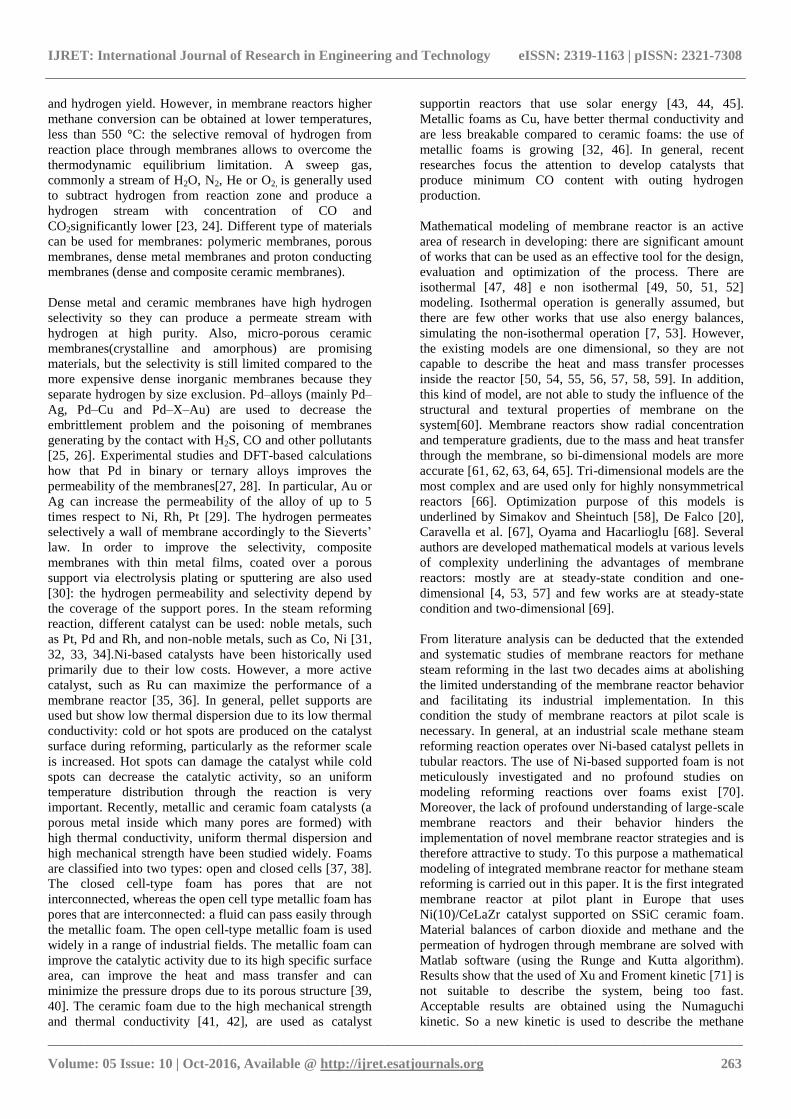
Fig. 1 shows the configuration of the integrated membrane
reactor that consists of an external steel tube (shell) with an
inner membrane wall tube where sweep gas (steam) flows to
drag the permeate hydrogen.
The selective membrane allows to obtain hydrogen with
high purityand to improve the conversion of the reaction,
despite the lower operating temperatures. Methane and
steam are continuously feeded: the molar ratio of steam to
carbon (S/C) is equal to 1:3, the maximum temperature is
550 °C and the maximum pressure of 10 atm over a
Ni(10)/CeLaZr catalyst supported on SSiC ceramic foam.
The flexibility on providing heat is externally ensured by
utilizing solar energy and molten salts, as the binary mixture
of NaNO3/KNO3 (60/40 %w/w) called ―solar salts‖. This
heat transfer fluid has low cost, allowing mismatch between
the fluctuating solar source and the operation of the
chemical plant.
Fig-1: Section of the integrated membrane reactor
Table 1: Dimensions of the integrated membrane reactor
Internal
diameter
(mm)
External
diameter (mm)
Membrane support 10 14
Palladium membrane n.a. n.a.
Catalyst 16 40
Shell reactor 42.7 48.3
Tube of sweep gas 6 9
A pseudo-homogeneous, one-dimensional and isothermal
model is developed to simulate the performance of the
integrated membrane reactor. The main assumptions of the
models are the following: stationary condition, cylindrical
symmetry, catalytic bed in isothermal conditions, one-
dimension model, modeling of pseudo-homogeneous
catalytic bed with mechanical, thermal and kinetic
equivalence to a granular bed, the polarization phenomena
for concentration is not considered, the inhibition
phenomena due to the impurities are negligible, co-current
flow mode. The assumption of the isothermal operation is
guaranteed by the use of molten salts. Infect, the assumption
of isothermal operation in a reactor is related to the higher
reaction heat respect to the heat loss/gain through the reactor
walls. According to this, for the reactor of this research,
ahigh ratio between heat transfer area and reaction volume is
present, respecting the first consideration. However, this
condition may not be true whit higher process scales [53].
2.2 XU and Froment Kinetic Reaction According to
the Langmuir-Hinshelwood Model
Methane steam reforming consists in two endothermic
reactions and the exothermic water-gas swift reaction
according the following scheme (See eq. 1-3):
𝐶𝐻4 + 𝐻2𝑂 ↔ 𝐶𝑂 + 3 ∙ 𝐻2 (1)
𝐶𝑂 + 𝐻2𝑂 ↔ 𝐶𝑂2 + 𝐻2 (2)
𝐶𝐻4 + 2 ∙ 𝐻2𝑂 ↔ 𝐶𝑂2 + 4 ∙ 𝐻2 (3)
The reaction enthalpy is respectively equal to 206, -41, 165
kJ/mol and the overall products are CO, CO2 and H2. The
third reaction is a linear combination of the other reactions.
The mathematical model of the kinetic follows the
Langmuir-Hinshelwood mechanism according to Xu and
Froment [71]. The rates of reactions are (See eq. 4-7):
𝑟1 =
𝑘1
𝑃𝐻22.5 ∙ (𝑃𝐶𝐻4 ∙ 𝑃𝐻2𝑂 −
𝑃𝐻23 ∙ 𝑃𝐶𝑂𝐾1
)
𝐷𝐸𝑁2 (4)
𝑟2 =
𝑘2
𝑃𝐻2∙ (𝑃𝐶𝐻4 ∙ 𝑃𝐻2 −
𝑃𝐻2 ∙ 𝑃𝐶𝑂𝐾2
)
𝐷𝐸𝑁2 (5)
𝑟3 =
𝑘3
𝑃𝐻23.5 ∙ (𝑃𝐶𝐻4 ∙ 𝑃𝐻2𝑂
2 −𝑃𝐻2
4 ∙ 𝑃𝐶𝑂2
𝐾3)
𝐷𝐸𝑁2 (6)
𝐷𝐸𝑁
=1 + 𝐾𝐶𝑂 ∙ 𝑃𝐶𝑂 + 𝐾𝐻2 ∙ 𝑃𝐻2 + 𝐾𝐶𝐻4 ∙ 𝑃𝐶𝐻4 + 𝐾𝐻2𝑂 ∙ 𝑃𝐻2𝑂
𝐻2
(7)
where rj(j=1−3) are the reaction rates, kj are the reaction
constants according Arrhenius relation kj= k0jexp(−Ej/R∙T),
Ki(i=CH4, H2O, H2, CO) are the adsorption constants
expressed as Ki=K0
iexp(−ΔHi/R∙T). In the system reaction,
only the first and second reactions are linearly independent:
the expressions for methane and carbon dioxide conversion
are the following (See eq. 8-9):
IJRET: International Journal of Research in Engineering and Technology eISSN: 2319-1163 | pISSN: 2321-7308
_______________________________________________________________________________________________
Volume: 05 Issue: 10 | Oct-2016, Available @ http://ijret.esatjournals.org 265
𝑋𝐶𝐻4 =𝐹𝐶𝐻4𝑜 − 𝐹𝐶𝐻4
𝐹𝐶𝐻4𝑜 (8)
𝑋𝐶𝑂2 =𝐹𝐶𝑂2𝑜 − 𝐹𝐶𝑂2
𝐹𝐶𝑂2𝑜 (9)
where XCH4 and XCO2 are the methane and carbon dioxide
conversion respectively, FCO2 and FCH4the flow rate of
carbon dioxide and methane respectively, F°CH4 and F°CO2
respectively the initial methane and carbon dioxide flow
rate. The expressions for partial pressures of components are
a function of the conversions (See eq. 10-16):
𝑃𝐶𝐻4 =(1 − 𝑋𝐶𝐻4)
𝜍 (10)
𝑃𝐶𝑂 =(𝜃𝐶𝑂 − 𝑋𝐶𝑂2 + 𝑋𝐶𝐻4)
𝜍 (11)
𝑃𝐶𝑂2 =(𝜃𝐶𝑂2 + 𝑋𝐶𝑂2)
𝜍 (12)
𝑃𝐻2𝑂 =(𝜃𝐶𝑂 − 𝑋𝐶𝐻4 − 𝑋𝐶𝑂2)
𝜍 (13)
𝑃𝐻2 =(𝜃𝐻2 + 3 ∙ 𝑋𝐶𝐻4 − 𝑋𝐶𝑂2 − 𝑌𝐻2)
𝜍 (14)
𝜍 =(1 + 𝜃𝐻2𝑂 + 𝜃𝐶𝑂 + 𝜃𝐶𝑂2 + 𝜃𝐻2)
𝑃𝑇 (15)
𝜃𝑗 =(𝐹𝑗
𝑜)
𝐹𝐶𝐻4𝑜 (16)
where PT is the total pressure and Fj° the initial flow rate of j
species [72]. The values of parameters of these equations in
the simulated system are present in Table 2 and 3.
Table 2: Values of adsorption constants for the compounds
involved in the reactions
CH4 H2O CO H2
K (1/bar) 6.65∙10-4
1.77∙10-5
8.23∙10-5
6.12∙10-9
Table 3: Values of kinetic parameters of the involved
reactions
Reaction steam
reforming
water gas
shift
methanatio
n
ko
(kmolbar0.5
/kgcath)
4.22∙1015
1.95∙1015
1.02∙1015
Activation energy
(J/mol)
240100 67130 243900
The hydrogen permeation through the palladium membrane
involves with the dissociation of molecular hydrogen and
the diffusion of their atoms. The flux of hydrogen depends
by membrane properties and driving force (the square root
of hydrogen partial pressures on both sides of the
membrane) [73] (See eq. 17):
𝐽𝐻2 =𝑄𝑝𝑑
𝛿∙ 𝑃𝐻2,𝑟
0.5 − 𝑃𝐻2,𝑝0.5 (17)
where δ is the membrane thickness, Qpd the permeation of
hydrogen, PH2,rand PH2,p the hydrogen pressure in permeate
and reaction side respectively. The permeation coefficient of
hydrogen is a function of the temperature according the
Arrhenius equation, as below (See eq. 18):
𝑄𝑝𝑑 = 𝑄𝑜 ∙ 𝑒𝑥𝑝 ∙ −𝐸𝑝
𝑅 ∙ 𝑇 (18)
A differential form of hydrogen flow is expressed by the
following relationship (See eq. 19):
𝑑𝐹𝐻2,𝑝𝑒𝑟𝑚
𝑑𝑥= 𝐽𝐻2 ∙ 2 ∙ 𝜋 ∙ 𝑟° + 𝛿 (19)
with ro the inner radius and δ the thickness of the membrane.
Considering the variable YH2 as the ratio between the
hydrogen flow in the permeation side and the initial flow of
methane, it is possible to obtain this differential equation
(see eq. 20):
𝑑𝑌𝐻2
𝑑휀 =
𝑄𝑝𝑑 ∙ 2 ∙ 𝜋 ∙ 𝑟° + 𝛿 ∙ 𝐿
𝛿∙ 22.4 ∙ 𝐹𝐶𝐻 ,4
°
∙ 𝑃𝐻2,𝑟0.5 − 𝑃𝐻2,𝑝
0.5 (20)
where ξ is the dimensionless length of the reactor, FoCH4 the
initial flow rate of methane and L the length of the reactor.
The mass balance for the gaseous phase is according this
expression (See eq. 21):
𝑑𝐹𝑖𝑑𝑥
= 𝜌 ∙ Ω ∙ 𝑣𝑖𝑗 ∙ 𝑟𝑗 ∙ 𝜂𝑗
𝑁𝑅=3
𝑗=1
(21)
For the flow of methane and the carbon dioxide, result (See
eq. 22-23):
𝑑𝐹𝐶𝐻4
𝑑𝑥= 𝜌 ∙ Ω ∙ 𝑟1 ∙ 𝜂1 + 𝑟3 ∙ 𝜂3 (22)
𝑑𝐹𝐶𝑂2
𝑑𝑥= 𝜌 ∙ Ω ∙ 𝑟2 ∙ 𝜂2 + 𝑟3∙𝜂3 (23)
where Ω is the reactor section, ρ is the catalyst density, η1,
η2, η3 are the effectiveness factors, r1, r2, r3 are the reaction
rates. The mathematical model that describes the process in
a dimensional form is the following (See eq. 24-26):
𝑑𝑋𝐶𝐻4
𝑑휀=
𝜌 ∙ Ω ∙ 𝐿
𝐹𝐶𝐻 ,4°
∙ 𝑟1 ∙ 𝜂1 + 𝑟3 ∙ 𝜂3 (24)
𝑑𝑋𝐶𝑂2
𝑑휀=
𝜌 ∙ Ω ∙ 𝐿
𝐹𝐶𝐻 ,4°
∙ 𝑟2 ∙ 𝜂2 + 𝑟3∙𝜂3 (25)

IJRET: International Journal of Research in Engineering and Technology eISSN: 2319-1163 | pISSN: 2321-7308
_______________________________________________________________________________________________
Volume: 05 Issue: 10 | Oct-2016, Available @ http://ijret.esatjournals.org 266
𝑑𝑌𝐻2
𝑑휀 =
𝑄𝑝𝑑 ∙ 2 ∙ 𝜋 ∙ 𝑟° + 𝛿 ∙ 𝐿
𝛿∙ 22.4 ∙ 𝐹𝐶𝐻,4
°
∙ 𝑃𝐻2,𝑟0.5 − 𝑃𝐻2,𝑝
0.5 (26)
with dx=L∙dε. These equations are numerically solved
through the method of Runge and Kutta using these initial
conditions: z=0, XCH4=XCO2=0.Matlab software and
a4th
order algorithm are used for the numerical solution of
the differential equation; the step side is equal to 0.001. The
operating conditions and reactor parameters used for
modeling the integrated membrane reactor according the
previous equations are shown in Table 4.
2.3 Numaguchi Kinetic Reaction
In the methane steam reforming process, the mainly
independent reactions are the steam reforming and the shift
reaction as the following (See eq. 27-28):
𝐶𝐻4 + 𝐻2𝑂 ↔ 𝐶𝑂 + 3 ∙ 𝐻2 (27)
𝐶𝑂 + 𝐻2𝑂 ↔ 𝐶𝑂2 + 𝐻2 (28)
The kinetic rate is described by the hybrid equation of
Langmuir-Hinshelwood with the power law, assuming that
the surface reaction is the rate-determining step (See eq. 29-
30). α and β are the parameters for the adsorption term in the
power law expression, according the Freundlich adsorption
rate expression. m is the number of adsorption sites included
in the rate.
Table 4: Operating conditions and reactor parameters
Operating conditions and reactor parameters
Tubes number 10
Tube passage 1
Tube length 900 mm
Total length of membrane module 748 mm
GHSV 384 h-1
Catalyst volume 9.6 l
Duty of reaction 1870 kcal/h
Heat transfer coefficient, gas side 278 kcal/hm2°C
Heat transfer coefficient, salt side 142 kcal/hm2°C
Overall heat transfer coefficient 90 kcal/hm2°C
Membrane area 0.3 m2
Flow rate of molten salts 800 kg/h
𝑟𝑟𝑓
= 𝑘𝑅𝑜 ∙ exp −
𝐸𝑝
𝑅 ∙ 𝑇
∙𝑘𝑟 ∙ 𝑃𝐶𝐻4 ∙ 𝑃𝐻2𝑂 − 𝑃𝐶𝑂 ∙
𝑃𝐻23
𝑘𝑃
𝑃𝐶𝐻4𝛼𝑅 ∙ 𝑃𝐻2𝑂
𝛽𝑅 ∙ (1 + 𝐾𝑘 ∙ 𝑃𝑘)𝑘𝑘=1
𝑚 (29)
𝑘𝑟 = 𝑘𝑅𝑜 ∙ exp −
𝐸𝑝
𝑅 ∙ 𝑇 (30)
In methane steam reforming, the adsorption equilibrium
constant for steam is larger respect to other components. For
this reason, the rates of the reactions according the
Numaguchi kinetic are obtained [72] (See eq. 31-32):
𝑟𝑟𝑓 = 𝑘𝑅𝑜 ∙ exp −
𝐸𝑅
𝑅 ∙ 𝑇 ∙
𝑃𝐶𝐻4 − 𝑃𝐶𝐻4 𝑒𝑞
𝑃𝐶𝐻4𝛼𝑅 ∙ 𝑃𝐻2𝑂
𝛿𝑅 (31)
𝑟𝑠𝑓 = 𝑘𝑆𝑜 ∙ exp −
𝐸𝑠
𝑅 ∙ 𝑇
∙ 𝑃𝐶𝑂 − 𝑃𝐶𝑂 𝑒𝑞
𝑃𝐶𝐻4𝛼𝑠 ∙ 𝑃𝐻2𝑂
𝛿𝑠 (32)
where rrf is for the steam reforming reaction, rsf is for the
shift reaction, PCH4(eq) and PCO(eq) are the pressures at
equilibrium conditions and R the constant of universal gas.
Table 5 shows the values of parameters for the reactions
according the Numaguchi kinetic [72]:
Table 5: Values of parameters for Numaguchi kinetic
Fitted parameters
koR 92∙10
8
ER 106.87 kJ/mol
αR 0
δR 0.596
ko
S 8.688∙105
Es 54.531 kJ/mol
αS 0
δS 0
2.4 Experimental Analysis of Pressure Drops inside
the Foams
Ceramic or metallic foams with open structures are
important for industrial application, in recent years. Infect,
they have high specific surface area, high porosity, low
density, favorable mechanical, thermal and corrosion
resistance. For these reasons, they can be used as support in
the reaction catalyst [70]. It is necessary to increase the
knowledge of their hydrodynamic properties: studies are
about the relation of foam structural parameters to pressure
drops. A review of pressure drops correlations in foams is
provided by Edouard et al. [74] and are based on the Darcy–
Forchheimer equation (See eq. 33):
∆𝑃
∆𝐿=
𝜇
𝐾∙ u + 𝜌 ∙ 𝐶 ∙ 𝑢2 (33)
whereΔL is the thickness (or length) of the porous media, Δp
is the pressure drop, u is the flow velocity, ρ is the medium
density, μ is the medium viscosity, K is the permeability and
C is the drag force coefficient of the porous media. The term
ρCV2considers the inertia effects. For creeping flow in
porous media, the Darcy‘s law is obtained. The key
geometrical parameters of the foam are its porosity (ε)which
is the ratio of the void space(Vvoid) to total volume,

IJRET: International Journal of Research in Engineering and Technology eISSN: 2319-1163 | pISSN: 2321-7308
_______________________________________________________________________________________________
Volume: 05 Issue: 10 | Oct-2016, Available @ http://ijret.esatjournals.org 267
(Vtotal)occupied by the foam, the foam strut diameter (dstrut),
the mean pore diameter (dp),the pore per linear inch
number(ppi) and specific surface area as a ratio of the
surface in contact with the flow(S) to the whole volume
occupied by the foam. These parameters are correlated
between them.
For the measures of pressure drops a sample is used: SSiC
foams coated with Ni(10)/CeLaZr catalyst as reported in
Fig. 2.
Fig-2 a) Images of SSiCfoams coated with Ni(10)/CeLaZr
catalyst; b)Stereomicroscopic images of SSiCfoams coated
with Ni(10)/CeLaZr catalyst
Table 6 reports the characteristics of the catalyst sample.
Table 6: Characteristics of SSiC foams coated with
Ni(10)/CeLaZr catalyst
SSiC-foam Ni(10)/CeZrLa
M
(g)
df
(mm)
Hf
(mm)
ε
(%)
M
(g)
loading
(g/l)
1.62 14 21.2 84.24 0.9 275.78
The parameters of the catalyst as permeability and drag
coefficient are evaluated from the experimental measures of
pressure drops and the fitting of the obtained data. These
parameters are present in Darcy–Forchheimerrelation, so the
pressure drops of ceramic foam are characterized.
To evaluate these parameters, an experimental test is
realized: compressed air is sent within the sample, as Fig. 3
shows and the flow rate is measured by the position of
rotameters, as shown in Fig. 4 a. A system of solenoid
valves regulars the flow rate of compressed air. A digital
manometer and a differential pressure gauge measure the
pressure drops inside the foams, as shown in Fig. b.
Fig-3. Sample of catalyst inside the tube where compressed
air is sent from the bottom during the experimental tests
Fig-4. Experimental apparatus used to measure the pressure
drops inside the catalyst sample (fig. 4a shows the
rotameters used to measure the flow rate of compressed air,
fig. 4b shows the digital and differential manometer used to
measure the pressure drops)

IJRET: International Journal of Research in Engineering and Technology eISSN: 2319-1163 | pISSN: 2321-7308
_______________________________________________________________________________________________
Volume: 05 Issue: 10 | Oct-2016, Available @ http://ijret.esatjournals.org 268
An isotropy test is used to ensure the property of the
catalyst: the position of sample is inverted and compressed
air is sent again, while the digital and differential
manometer measure the pressure drops inside the catalyst.
3. RESULTS AND DISCUSSIONS
3.1 Modeling of the Integrated Membrane Reactor
Using the XU and Froment Kinetic Reaction
The equations system to model the integrated membrane
reactor is solved using the Xu and Froment kinetic reaction
and the trend of methane and carbon dioxide conversion as a
function of temperature and pressure is obtained, as shown
in the following figures. For the trend of methane and
carbon dioxide conversion, reported in Fig. 5 and 6
respectively, the results are comparable with the studies of
Shu et al. [75] and Lin et al. [76].
Fig-5. Performance of methane conversion as a function of
temperature and pressure inside the integrated membrane
reactor according to the Xu and Froment kinetic
Fig-6. Performance of carbon dioxide conversion as a
function of temperature and pressure inside the integrated
membrane reactor according to the Xu and Froment kinetic
For the integrated membrane reactor temperature and
pressure have a positive effect on methane and carbon
dioxide conversion: the chemical equilibrium is shift to the
products, resulting in higher conversion.
As the temperature increases, the hydrogen permeation rate
through the membrane and the reaction rate increase
producing a higher methane conversion. Equally, higher
pressures and therefore higher partial pressure inside the
reaction increases the driving force of hydrogen, resulting in
a higher conversion of methane. Infect, the fluid temperature
increases when the pressure increases. Conversions next to
unit are obtained for values of pressure next to 30 bar and
temperatures greater than 500 °C. Temperature and pressure
have an important role in the reaction kinetic, being the
reaction endothermic. A similar consideration can be drawn
for the hydrogen production, shown in Fig. 7. Higher
pressures contribute to the transfer of hydrogen from the
reaction zone to permeation zone; an ideal value of 4 is
asymptotically reached with a pressure of 30 bar [77]. The
positive effect of the pressure is less significant for values of
pressures that are higher than 5 bar. The yields of hydrogen
are proportional to methane conversion.
Fig-7. Performance of hydrogen yield as a function of
temperature and pressure inside the integrated membrane
reactor according to the Xu and Froment kinetic
Fig. 8 shows the methane conversion as function of pressure
and dimensionless length of the reactor. It is evident that the
kinetic reaction is very fast: the conversion is unitary in all
length of the reactor. Then, using data related to the existing
integrated membrane reactor, it is evident that the Xu and
Froment kinetic used in literature is not suitable for the
description of this process.
Fig-8. Performance of methane conversion as a function of
dimensionless length of the reactor and pressure inside the
integrated membrane reactor according to the Xu and
Froment kinetic

IJRET: International Journal of Research in Engineering and Technology eISSN: 2319-1163 | pISSN: 2321-7308
_______________________________________________________________________________________________
Volume: 05 Issue: 10 | Oct-2016, Available @ http://ijret.esatjournals.org 269
Fig. 9 shows the methane conversion as a function of
pressure and temperature. An optimal value of methane
conversion can be obtained with pressure and temperature
equal to 30 bar and 500 °C respectively.
Fig-9. Performance of methane conversion as a function of
temperature and pressure inside the integrated membrane
reactor in 3D plot according to the Xu and Froment kinetic
A comparison with a corresponding packed reactor can be
made by evaluating delta parameter, which represents the
efficiencies difference of the two types of reactors. As
shown in Fig. 10, high values of delta should indicate where
the membrane reactor is more efficient respect to a packed
reactor: with high pressures and medium temperatures the
integrated membrane reactor is advantageous respect to a
packed one.
Fig-10. Performance of delta function as a function of
temperature and pressure of the reactor
3.2 Modeling of the Integrated Membrane Reactor
Using the Numaguchi Kinetic Reaction
Fig. 11 and 12 show the results obtained by modeling the
system with theNumaguchi kinetic. In Fig. 11 the methane
conversion increases with the increase of pressure and
temperature, for the same reasons analyzed first. Analog
consideration can be treated for carbon dioxide conversion
as Fig. 12 shows.
Fig-11. Performance of methane conversion as a function
of temperature and pressure inside the integrated membrane
reactor according to the Numaguchi kinetic
Temperature and pressure have a positive effect on
hydrogen production as shown in Fig. 13. Fig. 14 shows the
methane conversion as a function of pressure and
dimensionless of the reactor: the used kinetic is suitable to
describe the process. The pressure has a positive effect on
dimensionless length and the trend is similar to works of
Kyriakides et al. [77], Patrascu and Sheintuch [44] and
Castillo et al. [78]. High value of methane conversion can be
obtained with high pressure.
Fig-12. Performance of carbon dioxide conversion as a
function of temperature and pressure inside the integrated
membrane reactor according to the Numaguchi kinetic
Fig-13. Performance of hydrogen yield as a function of
temperature and pressure inside the integrated membrane
reactor according to the Numaguchi kinetic.

IJRET: International Journal of Research in Engineering and Technology eISSN: 2319-1163 | pISSN: 2321-7308
_______________________________________________________________________________________________
Volume: 05 Issue: 10 | Oct-2016, Available @ http://ijret.esatjournals.org 270
Fig-14. Performance of methane conversion as a function
of dimensionless reactor length and pressure inside the
integrated membrane reactoraccording to the Numaguchi
kinetic
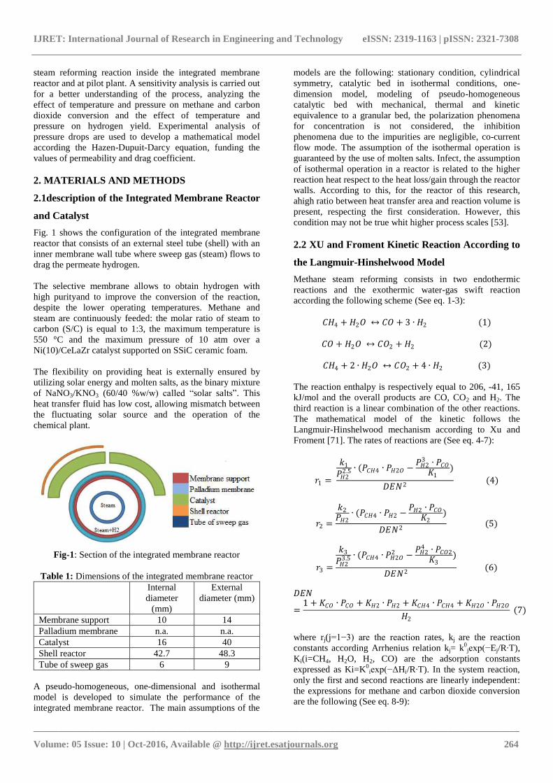
3.3 Experimental Analysis of Pressure Drops Inside
The Foams
Pressure drops through foams depend on foam
microstructure and fluid velocity. A correct estimations of
pressure drops inside the foams can be used to do some
previsions during the operation of the process. To this
purpose, parameters as permeability (K) and drag coefficient
(C) are important and should be defined properly. These
parameters are estimated by the fitting of experimental data,
according the model of Hazen-Dupuit-Darcy or called as
Forchheimer-extended Darcy equation [79]. The pressure
drops per unit of length as function of fluid velocity used in
experimental tests (compressed air)are provided according
the Hazen-Dupuit-Darcy equation (See eq. 34):
𝑦 = 34.55 ∙ 𝑢2 + 2.27 ∙ 𝑢 (34)
where y is the pressure drop per unit of length of catalyst
and u the fluid velocity, calculated dividing the volumetric
flow rate by the cross-sectional area. The pressure drops
across the foam are a quadratic function of the flow velocity.
The length of catalyst used in the experimental tests is equal
to 5 cm while the section equal to 0.00203 m2. Fig. 15
shows the trend of pressure drops as a function of fluid
velocity: the experimental results are in good agreement
with the model with R2>98%. Also, the trend is according to
previous studies of Bhattacharya et al. [80] and Boomsma
and Poulikakos [81]: the pressure drops increase with the
increasing of velocity according a quadratic equation.
Results suggest that the pressure drops of foams are much
lower compared to a packed bed of spheres and short
contact times are present. Richardson et al. [82] find that the
pressure drops through foams are about ten times lower
respect to a spherical particles fixed bed.
Fig-15. Performance of pressure drops per unit of length of
catalyst as a function of fluid velocity used in the
experimental tests
The value of permeability K and drag coefficient C of
ceramic foam obtained from the regressions of experimental
data are equal to 4.89∙10-7
m2
and 1.81 s2/m respectively.
The value of K and C are calculated as K=μ/α and C=β/ρ,
where dynamic viscosity (μ) and density of compressed air
(ρ) are taken as 0.000017 kg/ms and 1.225 kg/m3,
respectively. K and C values are related to the pore
diameters of the foams: in general, the pore diameter has a
positive effect on K parameter and negative effect on C
parameter. [83]. Several works show the relation between
porosity and permeability: the permeability increases with
the increasing of porosity [80, 81]. The concentrated
pressure drops produced during the experimental tests are
neglected, because are insignificant (between 0 and 0.06
mmH2O/mm, as obtained by experimentation). The drag
force C allows to have an accurate estimation of the pressure
drops and depends on porosity [83]. Diedericks and Du
Plessis [85] show that coefficient C is significant with
higher flow velocity. Permeability of the metal foam is
more accurate if determined experimentally and it is
difficult to model due to the complex structure of these
materials. Several researchers correlate the permeability
with structural parameters of metal foam [81]. Antohe et al.
[86] show that K and C are related to fluid velocity.
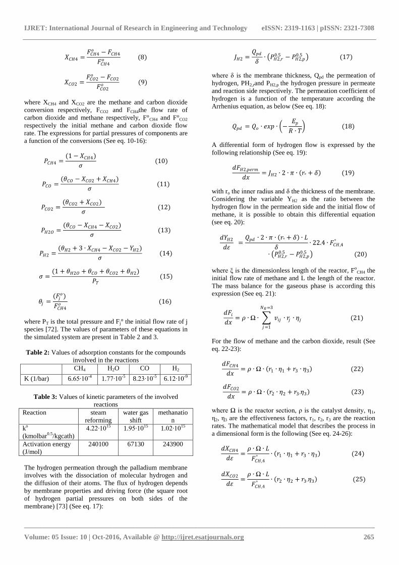
From isotropy test it is possible to notice that the catalyst
does not respect this property because the equation for
pressure drops is not equal to that found previously (See eq.
35).
𝑦 = 35.66 ∙ 𝑢2 + 8.56 ∙ 𝑢 (35)
where y is the pressure drop per unit of length of catalyst
and u the fluid velocity. Fig. 16 shows the trend of pressure
drops as a function of fluid velocity. In this case, the value
of K and C coefficients are respectively equal to 4.76∙10-7
m2 and 6.84 s
2/m.
0
10
20
30
40
50
60
70
80
0 0.5 1 1.5
P/L
(P
a/m
m)
u (m/s)
IJRET: International Journal of Research in Engineering and Technology eISSN: 2319-1163 | pISSN: 2321-7308
_______________________________________________________________________________________________
Volume: 05 Issue: 10 | Oct-2016, Available @ http://ijret.esatjournals.org 271
Fig-16. Performance of pressure drops per unit of length of
catalyst as a function of fluid velocity used in the
experimental isotropy tests
4. CONCLUSION
Pure hydrogen production is of great interest, because
hydrogen is an energy green carrier and methane steam
reforming is commonly used for its production. Integrated
membrane reactors enable a pure hydrogen stream and
allows that the reaction take places at significantly lower
temperatures than conventional reactors. Infect, membrane
reactors can do the reaction and separation simultaneously
in order to produce hydrogen.
In this research methane steam reforming in an integrated
membrane reactor is studied experimentally and from a
modeling point of view. Catalyst supported on ceramic foam
(SSiC foams coated with Ni(10)/CeLaZr) is used to ensure
an uniform temperature distribution. It is a first integrated
membrane reactor at pilot plant in Europe.
Results suggest that the Xu and Froment kinetic, commonly
used in the literature, is not suitable to describe the system,
being very fast. Acceptable results are obtained using the
Numaguchi kinetic. So a new kinetic is used to describe a
methane steam reforming reaction inside the integrated
membrane reactor.
An analysis to study the effect of pressure and temperature
is carried out: these parameters have a positive effect on
methane and carbon dioxide conversion and hydrogen yield.
The developed model can form the basis for an optimal
design and process control studies of reactor system aiming
at high methane conversion, high hydrogen recovery yield
and a suitable energy management procedure, while
ensuring safe operating conditions. Several experimental
tests are carried out to measure the pressure drops inside the
catalyst sample according the Hazen-Dupuit-Darcy
equation; from regression of experimental data, drag
coefficient and permeability are obtained. The isotropic test
of this kind of foam is not satisfied.
ACKNOWLEDGEMENT
The author of the study would like to thank the European
Commission for funding this work.
REFERENCES
[1]. Y.W. Ohmori, S. Kataoka, T. Yamamoto, A. Endo, M.
Nakaiwa, et al. A comparative simulation study of methane
steam reforming in a porous ceramic membrane reactor
using nitrogen and steam as sweep gases. International
Journal of Hydrogen Energy. 33 (2008) 685-92.
[2]. D. Dasa, T.N. Veziroglu, Advances in biological
hydrogen production processes. Int. J. Hydrogen Eng. 33
(2008) 6046-57.
[3]. M.P. Gimeno, Z.T.Wub, J. Solerc, J. Herguidoa, K. Lib,
M. Menéndez, Combination of a Two-Zone Fluidized Bed
Reactor with a Pd hollow fiber membrane for catalytic
alkane dehydrogenation. Chemical Engineering Journal. 155
(2009) 298–303.
[4]. A. Brunetti, A. Caravella, G. Barbieri, E. Drioli,
Simulation study of water gas shift reaction in a membrane
reactor. J. Membr. Sci. 306 (1–2) (2007) 329–340.
[5]. M. Sjardin, K.J. Damen, A.P.C. Faaij, Techno-economic
prospects of small-scale membrane reactors in a future
hydrogen-fuelled transportation sector. Energy 31 (2006)
2523–2555.
[6]. L. Capobiancoa, Z. Del Pretea, P. Schiavettia, V.
Violante, Theoretical analysis of a pure hydrogen
production separation plant for fuel cells dynamical
applications. International Journal of Hydrogen Energy. 31
(2006) 1079 – 1090.
[7]. J. Tong, Y. Matsumura, Pure hydrogen production by
methane steam reforming with hydrogen-permeable
membrane reactor. Catalysis Today. 111 (2006) 147–152.
[8]. M. Saric, Y.C. van Delft, R.Sumbharaju, D.F. Meyer,
Arend de Groot, Steam reforming of methane in a bench-
scale membrane reactor at realistic working conditions.
Catalysis Today. 193 (2012) 74– 80.
[9]. Y. Bi, H. Xu, W.Li, A. Goldbach, Water–gas shift
reaction in a Pd membrane reactor over Pt/Ce0.6Zr0.4O2
catalyst. International journal of hydrogen energy. 34 (2009)
2965–2971.
[10]. L.C. Silva, V.V. Murata, C.E. Hori, A.J. Assis,
Optimization of a Membrane Reactor for Hydrogen
Production Through Methane Steam Reforming Using
Experimental Design Techniques and NPSOL, EngOpt 2008
- International Conference on Engineering Optimization,
Rio de Janeiro, Brazil, 01-05 June 2008.
[11]. H.W. Deckeman, J.W. Fulton, J.M. Grenda, F.
Hershkowitz, Electric power generation with heat
exchanged membrane reactor. CA2414657 (C)―2011-05-
24.
[12]. W. Sufang, W. Cheng, W. Xieqing, Decarburization
and dehydrogenation double-intensification methane and
steam reforming hydrogen production method and device,
CN102674247 (A)―2012-09-19.
[13]. Y. Mei, L. Shulian, J. Fengjun, C. Guangwen, Method
for producing hydrogen by reforming methanol steam.
CN102145876 (A) ― 2011-08-10
0
10
20
30
40
50
60
70
80
0 0.5 1 1.5
P/L
(P
a/m
m)
u (m/s)
IJRET: International Journal of Research in Engineering and Technology eISSN: 2319-1163 | pISSN: 2321-7308
_______________________________________________________________________________________________
Volume: 05 Issue: 10 | Oct-2016, Available @ http://ijret.esatjournals.org 272
[14]. B. Morico, A.Salladini, G. Iaquaniello, Method and
system for the production of the hydrogen, WO 2013137720
A1, 19-09-2013
[15]. Y. Chen, Y. Wang, H. Xu, G. Xiong, Hydrogen
production capacity of membrane reformer for methane
steam reforming near practical working conditions.
J.Membr. Sci. 322 (2008) 453–459.
[16]. B. Dittmar, A. Behrens, N. Schödel, M. Rüttinger, T.
Franco, G. Straczewski, R.Dittmeyer, Methane steam
reforming operation and thermal stability of newporous
metal supported tubular palladium composite membranes,
Int. J.Hydrogen Energy. 38 (2013) 8759–8771.
[17]. J. Xuan, M.K.H. Leung, D.Y.C. Leung, M. Ni,
integrating chemical kinetics with CFD modeling for auto-
thermal reforming of biogas. International Journal of
Hydrogen Energy. 34 (2009) 9076-86.
[18]. M. De Falco, G. Iaquaniello, A. Salladini,
Experimental tests on steam reforming of natural gas in a
reformer and membrane modules, (RMM) plant. Journal of
Membrane Science. 368 (1-2) (2011a) 264-274.
[19]. F. Borgognoni, S. Tosti, M. Vadrucci, A. Santucci,
Pure hydrogen production in a Pd–Ag multi-membranes
module by methane steam reforming.Int. J. Hydrogen
Energy. 36 (2011) 7550–7558.
[20]. M. De Falco, D. Barba, S. Cosenza, G. Iaquaniello, L.
Marrelli, Reformer and membrane modules plant powered
by a nuclear reactor or by a solar heated molten salts:
Assessment of the design variables and production cost
evaluation. International Journal of Hydrogen Energy. 33
(20) (2008) 5326-5334.
[21]. D.S.A. Simakov and M. Sheintuch, Experimental
optimization of an autonomous scaled-down methane
membrane reformer for hydrogen generation. Industrial and
Engineering Chemistry Research. 49 (3) (2010) 1123-1129.
[22]. R.Y. Chein, Y.C. Chen, Y. Sheng Lin, J.N. Chung,
Experimental study on the hydrogen production of
integrated methanol-steam reforming reactors for PEM fuel
cells. International Journal of Thermal Sciences. 50 (2011)
1253-1262.
[23]. W. Yu, T. Ohmoria, S. Kataokaa, T. Yamamotoa, A.
Endoa, M. Nakaiwaa, N. Itoh, A comparative simulation
study of methane steam reforming in a porous ceramic
membrane reactor using nitrogen and steam as sweep gases.
International Journal of hydrogen energy. 33 (2008) 685-
692.
[24]. D. Mendes, S. Sa, S. Tosti, J.M. Sousa, L.M. Madeira,
A. Mendes, Experimental and modeling studies on the low-
temperature water-gas shift reaction in a dense Pd-Ag
packed-bed membrane reactor. Chem. Eng. Sci. 66 (2011)
2356-67.
[25]. A.S. Augustine, Y.H. Ma, N.K. Kazantzis, High
pressure palladium membrane reactor for the high
temperature water-gas shift reaction. International Journal of
Hydrogen Energy. 36 (2011) 5350-60.
[26]. R. Sanz, J.A. Calles, D. Alique, L. Furones, S.
Ordonez, P. Marın, et al. Preparation, testing and modelling
of a hydrogen selective Pd/YSZ/SS composite membrane.
International Journal of Hydrogen Energy. 36 (2011) 15783-
93.
[27]. S. Hao, D.S. Sholl, Computational prediction of
durable amorphous metal membranes for H2 purification. J.
Membr. Sci. 381 (1–2) (2011) 192–196.
[28]. E. Ozdogan, J. Wilcox, Investigation of H2 and H2S
adsorption on niobium-and copper-doped palladium
surfaces. J. Phys. Chem. B 114 (40) (2010) 12851–12858.
[29]. C.G. Sonwane, J. Wilcox, Y.H. Ma, Solubility of
hydrogen in Pd/Ag and Pd/Au binary alloys using density
functional theory. J. Phys. Chem. B. 110 (48) (2006) 24549–
24558.
[30]. S. Tosti, L. Bettinali, S. Castelli, F. Sarto, S. Scaglione,
V. Violante, Sputtered, electroless, and rolledpalladium-
ceramicmembranes. J Membr Sci. 196 (2002) 241-9.
[31]. J.T. Richardson, M. Garrait, J.K. Hung, Carbon
dioxide reforming with Rh and Pt-Re catalysts dispersed on
ceramic foam supports. Applied Catalysis A: General. 225
(2003) 69–82.
[32]. N. Gokon, Y. Osawa, D. Nakazawa, T. Kodama,
Kinetics of CO2 reforming of methane by catalytically
activatedmetallic foam absorber for solar receiver-reactors.
International Journal of Hydrogen Energy. 34 (2009) 1787–
1800.
[33]. L. Giani, C. Cristiani, G. Groppi, E. Tronconi,
Washcoating method for Pd/γ-Al2O3 deposition on metallic
foams, Applied Catalysis B: Environmental. 62 (2006) 121–
131.
[34]. K. Sutthiumporn, T. Maneerung, Y. Kathiraser, S.
Kawi, CO2 dry-reforming of methane over
La0.8Sr0.2Ni0.8M0.2O3 perovskite (M =Bi, Co, Cr, Cu,
Fe): roles of lattice oxygen on C-H activation and carbon
suppression. International Journal of Hydrogen Energy. 37
(2012) 11195–11207.
[35]. A. Iulianelli et al., H2 production by low pressure
methane steam reforming in a Pd–Ag membrane reactor
over a Ni-based catalyst: experimental and modeling. Int. J.
Hydrogen Energy. 35 (20) (2010) 11514–11524.
[36]. H.F. Chang et al., Auto-thermal reforming of methane
for producing highpurity hydrogen in a Pd/Ag membrane
reactor, Int. J. Hydrogen Energy. 35 (23) (2010) 12986–
12992.
[37]. C.Y. Zhao, Review on thermal transport in high
porosity cellular metal foams with open cells. International
Journal of Heat and Mass Transfer. 55 (2012) 3618–3632.
[38]. P.J. Tan, S.R. Reid, J.J. Harrigan, Z. Zou, S. Li,
Dynamic compressive strength properties of aluminum
foams, Part I — experimental data and observations. Journal
of the Mechanics and Physics of Solids. 53 (2005) 2174–
2205.
[39]. S. Lim and J. Bae, Auto-thermal reforming over a
Pt/Gddoped ceria catalyst: Heat and mass transport
limitations in the steam reforming section. Int. J. Hydrogen
Energy. 35 (2010) 6717-6725.
[40]. W. Lu, C.Y. Zhao. Thermal analysis on metal-foam
filled heat exchangers. Part I: Metal-foam filled pipes, Int. J.
Heat Mass Transfer. 49 (2006) 2751–2761.
[41]. N. Gokon, Y. Yamawaki, D. Nakazawa,T.Kodama,
Ni/MgO-Al2O3 and Ni-Mg-O catalyzedSiC foam
absorbersfor high temperature solar reforming of methane.
Int.J.Hydrogen Energy. 35 (2010) 7441–7453.
[42]. H. Liu, S. Li, S. Zhang, J. Wang, G. Zhou, L. Chen, X.
Wang, Catalytic performance of novel Ni catalysts

IJRET: International Journal of Research in Engineering and Technology eISSN: 2319-1163 | pISSN: 2321-7308
_______________________________________________________________________________________________
Volume: 05 Issue: 10 | Oct-2016, Available @ http://ijret.esatjournals.org 273
supported onSiC monolithic foam in carbon dioxide
reformingof methane to synthesis gas. Catal. Commun 9
(2008) 51–54.
[43]. J. Qi, Y. Sunb, Z. Xiec, M. Collins, H. Dua, T. Xiong,
Development of Cu foam-based Ni catalyst for solar thermal
reforming of methane with carbon dioxide. Journal of
Energy Chemistry. 24 (2015) 786–793.
[44]. M. Patrascu, M. Sheintuch, On-site pure hydrogen
production by methane steam reforming in high flux
membrane reactor: Experimental validation, model
predictions and membrane inhibition. Chemical Engineering
Journal. 262 (2015) 862–874.
[45]. H. Roh, D. Lee, K. Koo, U. Jung, W. Yoon, Natural
gas steam reforming for hydrogen production overmetal
monolith catalyst with efficient heat-transfer. Int. J.
Hydrogen Energy. 35 (2010) 1613–1619.
[46]. L. Sang, B. Sun, H. Tan, C. Du,Y. Wu, C. Ma,
Catalytic reforming of methane with CO2over metal
foambased monolithic catalysts. Int. J. Hydrogen Energy 37
(2012) 13037–13043.
[47]. F. Gallucci, L. Paturzo, A. Basile, A simulation study
of steam reforming of methane in a dense tubular membrane
reactor. Int J Hydrogen Energy. 29 (2004) 611-7.
[48]. J. Oklany, K. Hou, R. Hughes, A simulative
comparison of dense and microporous membrane reactors
for the steam reforming of methane. Appl. Catal. A Gen.
170 (1998) 13-22.
[49]. M. De Falco, L. Di Paola, L. Marrelli, P. Nardella,
Simulations of large-scale membrane reformers by a two-
dimensional model. Chem. Eng. J. 128 (2-3) (2007) 115-25.
[50]. K.S. Patel, A.K. Sunol, Modeling and simulation of
methane steam reforming in a thermally coupled membrane
reactor. International Journal of Hydrogen Energy. 32
(2007) 2344-58.
[51]. G. Marigliano, G. Barbieri, E. Drioli, Effect of energy
transport on a palladium-based membrane reactor for
methane steam reforming process. Catal Today. 67 (2001)
85-99.
[52]. F.A.N. Fernandes, A.B. Soares Jr, Methane steam
reforming modeling in a palladium membrane reactor.Fuel.
85 (2006) 569-573.
[53]. M.E. Adrover, E. Lopez, D.O. Borio, M.N. Pedernera,
Theoretical study of a membrane reactor for the water gas
shift reaction under nonisothermal conditions. A.I.Ch.E. J.
55 (12) (2009) 3206–3213.
[54]. A. Caravella, F.P. Di Maio, A. Di Renzo, Optimization
of membrane area and catalyst distribution in a
permeativestage membrane reactor for methane steam
reforming. Journal of Membrane Science. 321 (2008) 209-
21.
[55]. J. Huppmeier, M. Baune, J. Thoming, Interactions
between reaction kinetics in ATR-reactors and transport
mechanisms in functional ceramic membranes: a simulation
approach. Chemical Engineering Journal. 142 (2008) 225-38
[56]. Z.B. Rui, K. Zhang, Y.D. Li, Y.S. Lin, Simulation of
methane conversion to syngas in a membrane reactor: Part I
A model including product oxidation. International Journal
of Hydrogen Energy. 33 (2008) 2246-53.
[57]. K. Gosiewski, K. Warmuzinski, M. Tanczyk,
Mathematical simulation of WGS membrane reactor for gas
from coal gasification. Catalysis Today. 156 (2010) 229-36.
[58]. D.S.A. Simakov, M. Sheintuch, Model-based
optimization of hydrogen generation by methane steam
reforming in auto-thermal packed-bed membrane reformer.
AIChE Journal. 57 (2011) 525-41.
[59]. M.E. Ayturk, N.K. Kazantzis, Y.H. Ma, Modeling and
performance assessment of Pd- and Pd/Au-based catalytic
membrane reactors for hydrogen production. Energy and
Environmental Science. 2 (2009) 430-8.
[60]. N.S. Abo-Ghander, J.R. Grace, S.S.E.H. Elnashaie, C.
Jim Lim, Modelling of a novel membrane reactor to
integrate dehydrogenation of ethylbenzene to styrene with
hydrogenation of nitrobenzene to aniline. Chem. Eng. Sci.
63 (2008) 1817–1826.
[61]. S.T. Oyama, P. Hacarlioglu The boundary between
simple and complex descriptions of membrane reactors: the
transition between 1-D and 2-D analysis. Journal of
Membrane Science. 337 (2009) 188-99.
[62]. T.P. Tiemersma, C.S. Patil, M.V. Annaland, J.A.M
Kuipers, Modelling of packed bed membrane reactors for
auto-thermal production of ultrapure hydrogen. Chemical
Engineering Science. 61 (2006) 1602-16.
[63]. J. Xuan, M.K.H. Leun, D.Y.C. Leung, M. Ni.
Integrating chemical kinetics with CFD modeling for auto-
thermal reforming of biogas. International Journal of
Hydrogen Energy. 34 (2009) 9076-86.
[64]. M.E.E. Abashar, A.A. Al-Rabiah, Production of
ethylene and cyclohexane in a catalytic membrane reactor,
Chem. Eng. Proc. 44 (2005) 1188–1196.
[65]. P. Marin, Y. Patino, F.V. Dıez, S. Ordonez, Modelling
of hydrogen perm-selective membrane reactors for catalytic
methane steam reforming. International journal of hydrogen
energy. 37 (2012) 18433-18445.
[66]. R.J. Byron Smith, L. Muruganandam, S. Murthy
Shekhar. CFD analysis of water gas shift membrane reactor.
Chemical Engineering Research and Design. 89 (2011)
2448-56.
[67]. A. Caravella, F.P. Di Maio, A. Di Renzo. Optimization
of membrane area and catalyst distribution in a
permeativestage membrane reactor for methane steam
reforming. Journal of Membrane Science. 321 (2008) 209-
21.
[68]. S.T. Oyama, P. Hacarlioglu. The boundary between
simple and complex descriptions of membrane reactors: the
transition between 1-D and 2-D analysis. Journal of
Membrane Science. 337 (2009) 188-99.
[69]. N.C. Markatos, E. Vogiatzis, M.K. Koukou, N.
Papayannakos, Membrane reactor modelling—a
comparative study to evaluate the role of combined mass
and heat dispersion in large-scale adiabatic membrane
modules. Chem. Eng. Res. Des. 83 (A10) (2005) 1171–
1178.
[70]. M.V. Twigg, J.T. Richardson, Fundamentals and
applications of structured ceramic foam catalysts.
IndEngChem Res. 46(12) (2007) 4166-77.
[71]. J. Xu, G.F. Froment, Methane steam reforming,
methanation and water-gas shift: Intrinsic Kinetics. AlChE
Journal. 35(1) (1989) 88-96.
[72].B.A. Finlayson, Nonlinear analysis in chemical
engineering, McGraw-Hill (1980) 60-171.
[73].G. Barbieri, A. Brunetti, G. Tricoli, E. Drioli, An
innovative configuration of a Pd-based membrane reactor
IJRET: International Journal of Research in Engineering and Technology eISSN: 2319-1163 | pISSN: 2321-7308
_______________________________________________________________________________________________
Volume: 05 Issue: 10 | Oct-2016, Available @ http://ijret.esatjournals.org 274
for the production of pure hydrogen. Experimental analysis
of water gas shift. J. PowerSources. 182 (2008) 160–167.
[74]. D. Edouard, M. Lacroix, P.C. Huu, F. Luck,Pressure
drop modeling on SOLID foam: State-of-the art correlation.
Chemical Engineering Journal. 144 (2008) 299-311.
[75]. J. Shu, B.P.A. Grandjean, S. Kaliaguine, Methane
steam reforming in asymmetric Pd- and Pd–Ag/porous SS
membrane reactors. Appl. Catal. A. 119 (1994) 305–325.
[76]. Y. Lin, Y.M. Liu, S.L. Chuanga, C.H. Chub, Effect of
incipient removal of hydrogen through palladium membrane
on the conversion of methane steam reforming:
experimental and modeling. Catalysis Today. 82 (2003)
127-139.
[77]. A.S. Kyriakides, L. Rodrıguez-Garcıa, S. Voutetakis,
D. Ipsakis, P. Seferlis, S. Papadopoulou, Enhancement of
pure hydrogen production through the use of a membrane
reactor. International Journal of Hydrogen Energy. 39
(2014) 4749-4760
[78]. J.M.V. Castillo, T. Sato, N. Itoh, Effect of temperature
and pressure on hydrogen production from steam reforming
of biogas with Pd-Ag membrane reactor. International
journal of hydrogen energy. 40 (2015) 3582-3591.
[79]. P. Khayargoli1, V. Loya, L. P. Lefebvre and M.
Medraj, The impact of microstructure on the permeability of
metal foams. CSME 2004 220-228.
[80]. A. Bhattacharya, V.V. Calmidi, R.L. Mahajan,
Thermophysical properties of high porosity metal foams. Int
J Heat Mass Transf. 45 (2002) 1017–1031.
[81]. K. Boomsma, D. Poulikakos, The effect of
compression and pore size variations on the liquid flow
characteristics in metal foams. ASME J Fluids Eng. 124
(2002) 263–272.
[82]. J.T. Richardson, Y. Peng, et al., Properties of ceramic
foam catalyst supports: pressure drop. Applied Catalysis A:
General. 204 (1) (2000) 19–32.
[83].J.W. Paek, B.H. Kang, S.Y. Kim, J.M. Hyun, Effective
Thermal Conductivity and Permeability of Aluminum Foam
Materials. Int. J. of Thermophysics. 21(2) 2000.
[84]. C. Beckermann, R. Viskanta, Forced convection
boundary layer flow and heat transfer along a flat plate
embedded in a porous medium, Int. J. of Heat and Mass
Transfer. 30 (1986) 1547–1551.
[85]. G.P.J. Diedericks and J.P. du Plessis, Electrical
conduction and formation factor in isotropic porous media,
Advances in Water Resources. 19 (4) (1996) 225-239.
[86]. B.V. Antohe, J.L. Lage, D.C. Price, R.M. Weber,
Experimental Determination of Permeability and Inertia
Coefficients of Mechanically Compressed Aluminum
Porous Matrices. J. of Fluids Engineering.119 (1997) 405-
412.
BIOGRAPHIES
Grazia Leonzio is a PhD student at
Department of Industrial and Information
Engineering and Economics, University of
L'Aquila, Via Giovanni Gronchi 18, 67100
L'Aquila, Italy; e-mail: