Materials Selection - 國立中興大學web.nchu.edu.tw/~jillc/me/Ch20 - Materials Selection.pdf ·...
29
CHAPTER 20 Materials Selection The manufacturer of this carbon-fiber reinforced composite bicycle uses a sophisticated software package [utilizing “finite element analysis”] to analyze how the frame will respond to stress, allowing the engineers to tailor the frame stiff- ness to the individual rider. (Courtesy of Algor, Inc.)
Transcript of Materials Selection - 國立中興大學web.nchu.edu.tw/~jillc/me/Ch20 - Materials Selection.pdf ·...

CHAPTER 20Materials Selection
The manufacturer of this carbon-fiber reinforcedcomposite bicycle uses a sophisticated softwarepackage [utilizing “finite element analysis”] toanalyze how the frame will respond to stress,allowing the engineers to tailor the frame stiff-ness to the individual rider. (Courtesy of Algor,Inc.)

T.S.Y.S.
E
SpecificationsUNS number. A92036
Chemical ComositionComposition limits. 0.50 max Si; 0.50 max Fe; 2.2 max Cu; 0.10 to 0.40 Mn; 0.30 to 0.6 Mg; 0.10 max Cr; 0.25 max Zn; 0.15 max Ti; 0.05 max others (each); 0.15 max others (total); bal Al
ApplicationsTypical uses. Sheet for auto body panels
Mechanical Properties
Tensile properties. Typical, for 0.64 to 3.18 mm (0.025 to 0.125 in.) flat sheet, T4 temper; tensile strength, 340 MPa (49 ksi); yield strength, 195 MPa (28 ksi); elongation, 24% in 50 mm or 2 in. Minimum, for 0.64 to 3.18 mm flat sheet, T4 temper; tensile strength, 290 MPa (42 ksi); yield strength, 160 MPa (23 ksi); elongation, 20% in 50 mm or 2 in.
Hardness. Typical, T4 temper: 80 HR15T strain-hardening exponent, 0.23
Elastic modulus. Tension, 70.3 GPa (10.2 × 10⁶ ksi); compression, 71.7 GPa (10.4 × 10⁶ ksi)
Fatigue strength. Typical, T4 temper: 124 MPa (18 ksi) at 107 cycles for flat sheet tested in reversed flexure
Figure 20-1 The basic mechanical properties obtained from the tensile test intro-duced in Chapter 6 lead to a list of engineering design parameters for a givenalloy. (The parameters are reproduced from a list in ASM Handbook, Vol.2, ASM International, Materials Park, Ohio, 1990.)

Materialproperties
Materialsscience
Materialsengineering
Structure
Atomic bondingCrystal structureDefect structureMicrostructureMacrostructure
Service performance
StressesCorrosionTemperatureRadiationVibration
Figure 20-2 Schematic illustration of the central role played by properties inthe selection of materials. Properties are a link between the fundamental is-sues of materials science and the practical challenges of materials engineer-ing. (From G. E. Dieter, in ASM Handbook, Vol. 20: Materials Selectionand Design, ASM International, Materials Park, Ohio, 1997, p. 245.)

DesignService conditions
FunctionCost
MaterialsProperties
AvailabilityCost
PropertiesEquipment selection
Influence on propertiesCost
Figure 20-3 Schematic illustration of the integral relationship amongmaterials, the processing of those materials, and engineeringdesign. (From G. E. Dieter, in ASM Handbook, Vol. 20: Ma-terials Selection and Design, ASM International, Materials Park,Ohio, 1997, p. 243.)

Engineeringcomposites
Lower E limitfor true solids
Woodproducts
Woods
Parallelto grain
Polymersfoams
You
ngs
mod
ulus
, E (
GP
a)
0.10.01
0.1
1.0
10
100
1000
0.3 1.0 3.0 10 30
Engineeringpolymers
Engineeringalloys
Engineeringceramics
Porousceramics
Diamond
SialonsSi
AluminasBe
Cork
Perpendicularto grain
Ash
MELPC
EpoxiesPMMA
PVC
HDPE
LDPEPTFE
Nylon
Polyesters
PlasticizedPVC
PUElastomers
PS
PPAsh
Oak
Oak
Pine
Pine
Fir
Fir
Hardbutyl
Softbutyl
Silicone
Balsa
Balsa
Spruce
B
MoAlloys
WC-Co
W alloys
Ni alloysCu alloys
Rock, stoneCement, concrete
GlassesPottery Ti alloys Zn alloys
Tinalloys
Leadalloys
Alalloys
Mgalloys
SteelsCFRPUni-ply
KFRPGFRP
CFRP
LaminatesGFRPKFRP
Ge
SiC
BeO
Si3N4
ZrO2
MODULUS-DENSITY
MFA:88-91
Figure 20-4 A materials property chart with a global view of relative materi-als performance. In this case, plots of elastic modulus and density data (onlogarithmic scales) for various materials indicate that members of the dif-ferent categories of structural materials tend to group together. (After M.F. Ashby, Materials Selection in Engineering Design, Pergamon Press, Inc.,Elmsford, N.Y., 1992.)

Sail
Batten
Board
Fin
Mast
Dagger board
Wishbone
Universaljoint
Figure 20-5 Components of a windsurfer design. The stiffness ofthe mast controls the sail shape, and the pivoting of the mastabout the universal joint controls the response of the craft. (Af-ter M. F. Ashby, “Performance Indices,” in ASM Handbook,Vol. 20: Materials Selection and Design, ASM International,Materials Park, Ohio, 1997, pp. 281–290.)

Engineeringcomposites
Lower E limitfor true solids
Woodproducts
Woods
Parallelto grain
Polymersfoams
You
ngs
mod
ulus
, E (
GP
a)
0.10.01
0.1
1.0
10
100
1000
0.3 1.0 3.0 10 30
Engineeringpolymers
Engineeringalloys
Engineeringceramics
Porousceramics
Diamond
SialonsSi
AluminasBe
Cork
Perpendicularto grain
Ash
MELPC
EpoxiesPMMA
PVC
HDPE
LDPEPTFE
Nylon
Polyesters
PlasticizedPVC
PUElastomers
PS
PPAsh
Oak
Oak
Pine
Pine
FirSpruce
Fir
Hardbutyl
Softbutyl
Silicone
Balsa
Balsa
Spruce
B
MoAlloys
WC-Co
W alloys
Ni alloysCu alloys
Rock, stoneCement, concrete
GlassesPottery Ti alloys Zn alloys
Tinalloys
Leadalloys
Alalloys
Mgalloys
SteelsCFRPUni-ply
KFRPGFRP
CFRP
LaminatesGFRPKFRP
Ge
SiC
BeO
Si3N4
ZrO2
MODULUS-DENSITY
MFA:88-91
Figure 20-6 The behavior of the windsurfer mast materials in Table 20.4 are su-perimposed on the ln E versus ln ρ chart of Figure 20–4 normalized by theshape factor, φ , of a thin-walled tube. For example, the CFRP mast with ashape factor of φ = 14.3 is shown at a position of (E/14.3, ρ/14.3) rela-tive to the (E, ρ) position of the bulk material for which φ = 1. (After M.F. Ashby, “Performance Indices,” in ASM Handbook, Vol. 20: MaterialsSelection and Design, ASM International, Materials Park, Ohio, 1997, pp.281–290.)

Figure 20-7 A drive sprocket made from dispersion-toughened nylon has re-placed aluminum and steel parts in many motocross racing designs. (Cour-tesy of the Du Pont Company, Engineering Polymers Division)
Stabilizer tips
Stabilizer fixedtrailing edgepanels
Rudder
Elevators
Wing to body fairing
Flap fairings(below wing)
Landing gear doors
Cowl components
Radome
Strut fairings
Upper and lower fixed leading edge
Ailerons(inboard andoutboard)
Spoilers(inboard andoutboard)
Upper and lower fixedtrailing edge
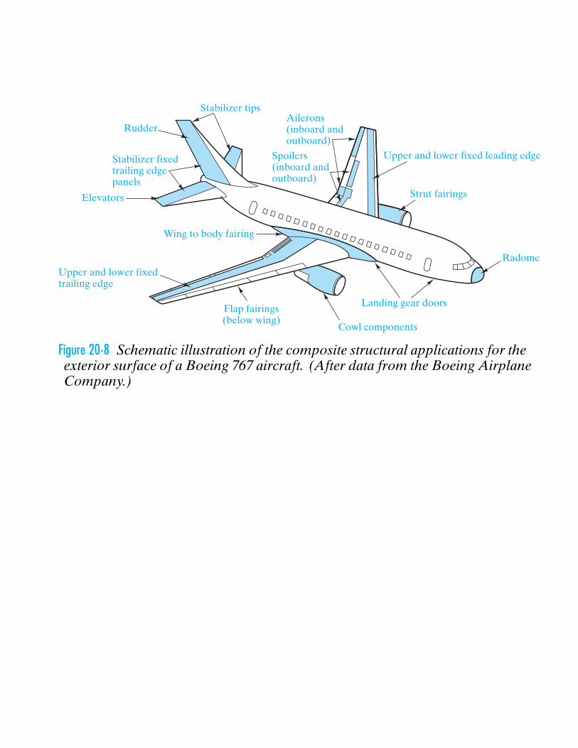
Figure 20-8 Schematic illustration of the composite structural applications for theexterior surface of a Boeing 767 aircraft. (After data from the Boeing AirplaneCompany.)

(a)
(b)
(c)
Ribbon
Free wall
Fabricatedsandwichpanel
Honeycomb
Adhesive
Face sheet
Face sheet
Node
Cellsize
Figure 20-9 (a) Hexagonal cell honeycomb is composed of (b) indi-vidual cells composed of adhesively bonded layers which are (c)subsequently bonded to face sheets to form the overall sandwichpanel. (After J. Corden, “Honeycomb Structure,” in EngineeredMaterials Handbook, Vol. 1, Composites, ASM International,Metals Park, Ohio, 1987, p. 721.)

1. The facings should be thick enough to withstandthe tensile, compressive, and shear stressesinduced by the design load.
2. The core should have sufficient strength towithstand the shear stresses induced by thedesign loads. Adhesive must have sufficientstrength to carry shear stress into core.
3. The core should be thick enough and havesufficient shear modulus to prevent overallbuckling of the sandwich under load, and toprevent crimping.
4. Compressive modulus of the core and thecompressive modulus of the facings should besufficient to prevent wrinkling of the faces underdesign load.
5. The core cells should be small enough to preventintracell dimpling of the facings under designload.
6. The core should have sufficient compressivestrength to resist crushing by design loads actingnormal to the panel facings or by compressivestresses induced through flexure.
7. The sandwich structure should have sufficientflexural and shear rigidity to prevent excessivedeflections under design load.
D
Figure 20-10 Structural design criteria for honeycomb structuralsandwich panels. (After J. Corden, “Honeycomb Structure,” inEngineered Materials Handbook, Vol. 1, Composites, ASM In-ternational, Metals Park, Ohio, 1987, p. 727.)

Figure 20-11 A scanning electron micrograph of sintered silica fibersin a Space Shuttle Orbiter ceramic tile. (Courtesy of Daniel Leiser,National Aeronautics and Space Administration [NASA])

HRSI
HRSI
HRSI
LRSI
LRSI
LRSI
LRSI
FRSI
FRSI
FRSI
RCC
RCC
HRSI and LRSI
Figure 20-12 Schematic illustration of the distribution of the components ofthe thermal protection system for the Space Shuttle Orbiter: felt reusablesurface insulation (FRSI), low-temperature reusable surface insulation (LRSI),high-temperature reusable surface insulation (HRSI), and reinforced carbon-carbon composite (RCC). (After L. J. Korb, et al., Bull. Am. Ceram. Soc.61, 1189 [1981].)

Gap
Airframe Filler bar
Coatedtiles Strain
isolatorpad
Adhesive
Figure 20-13 Schematic of a typical ceramic tile configuration in the thermal protection system for theSpace Shuttle Orbiter. (After L. J. Korb, et al., Bull. Am. Ceram. Soc. 61, 1189 [1981].)
Spine
Pelvis
AcetabulumHead
Femur
Healthyjoint
(a) (b) (c) (d)
Surgicalcut
CementfixationSurgically
drilled
Cementlessfixation
Damagedor
diseasedjoint
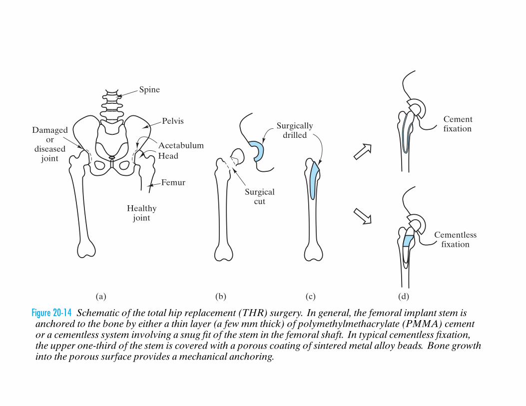
Figure 20-14 Schematic of the total hip replacement (THR) surgery. In general, the femoral implant stem isanchored to the bone by either a thin layer (a few mm thick) of polymethylmethacrylate (PMMA) cementor a cementless system involving a snug fit of the stem in the femoral shaft. In typical cementless fixation,the upper one-third of the stem is covered with a porous coating of sintered metal alloy beads. Bone growthinto the porous surface provides a mechanical anchoring.

Figure 20-15 A cobalt–chrome stem andball, with a polyethylene cup, form aball and socket system for an artificialhip joint. (Courtesy of DePuy, a Divi-sion of Boehringer Mannheim Corpo-ration.)

Figure 20-16 The Omnifit HA Hip Stem consists of hydrox-yapatite coating on a hip replacement prosthesis for the pur-pose of improved adhesion between the prosthesis and bone.Hydroxyapatite is the predominant mineral phase in naturalbone. (Courtesy of Osteonics, Allendale, New Jersey.)

(Courtesy of the University of California, Davis)

Figure 20-17 Transformer core winding using anamorphous ferrous alloy wire. (Courtesy ofAllied-Signal, Inc.)

Figure 20-18 Pole-mounted amorphous metal dis-tribution transformer. (Courtesy of Allied Sig-nal, Inc.)

Figure 20-19 Small transformer bobbins molded from a polyester thermoplastic are shown in the fore-ground. Wound, fully assembled transformers are in the background. (Courtesy of the Du Pont Com-pany, Engineering Polymers Division.)

Si chip
Si chip
Pb-SnPin
Glass
Ceramic substrate
Cupad
Oxide
Al
Figure 20-20 A schematic illustration of a flip-chip solder bonded to a ce-ramic substrate. The enlarged view shows Pb-Sn solder prior to bond-ing. (From J. W. Mayer and S. S. Lau, Electronic Materials Science:For Integrated Circuits in Si and GaAs, Macmillan Publishing Com-pany, New York, 1990.)

Injected electrons
Forwardbias Light
p type
p typerecombination
n type
Band gap, Eg
EF
EF
Figure 20-21 Schematic illustration of the energy band structure fora light-emitting diode (LED). (After R. C. Dorf, Electrical En-gineering Handbook, CRC Press, Boca Raton, Florida, 1993, p.750.)

SubstrateSubstrate
Light
Light
V
V
Gradedlayer
(b)(a)
Figure 20-22 Schematic illustration of (a) surface emitting and (b) edge emitting light-emitting diodes (LEDs).(After R. C. Dorf, Electrical Engineering Handbook, CRC Press, Boca Raton, Florida, 1993, p. 750.)

Integrated circuitcontaining BCD datalatch/decoder/LEDdrivers
Glass window
LEDs arranged ina modified 4x7 dotmatrix font
Hermetic seal atsubstrate rimwall-to-glassinterface
Ceramic substrate
Dark surfaceprovides positiveon/off contrast
External leadsbrazed to backof substrate
Figure 20-23 Schematic illustration of a digital display employing an array oflight-emitting diodes (LED). (From S. Gage et al., Optoelectronics/Fiber-Optics Applications Manual, 2nd ed., Hewlett-Packard/McGraw-Hill, NewYork, 1981.)

Platen
Paper
Ink ribbon
Guide
Wire
Wire
Wire guide
Headelement
Stroke amplifier
(a) (b)
Piezoelectricactuator
Figure 20-24 A schematic illustration of a ceramic actuator as an example of a smart material. The specific ap-plication is an impact dot-matrix printer. (a) Overall structure of the printer head. (b) Close-up of the multi-layer piezoelectric printer-head element. (From K. Uchino, MRS Bulletin, 18, 42 [1993].)

p-doped polyacetylenepolysulfur nitrideacid-doped polyanilinepoly (o-toluidine)
acid-doped poly(o-toluidine)
copper108
100
10–8
10–16
Conductors
ConductivityCategory
Semiconductors
Insulators
aluminumironsteel wire
lead sulfidegermanium
silicon
aluminum oxide
nylon 6/6borosilicate glasspolyethylene
Figure 20-25 Plot of the electrical conductivity of various electronic polymers,which challenge the conventional classifications given in Figure 15–28. (Af-ter A. J. Epstein, MRS Bulletin, 22, 19 [1997].)

RenewableResourcedepletion
Inputs
Greenhouseeffect
Atmosphereemissions
Wateremissions
Waste
Recovery
Classificationexercise
Emissionsdata
Ozonedepletion
Smoggeneration
Metallicpollution
Chemicalcontamination
Energyrecovery
Materialsrecovery
Nonrenewable
Feedstock energy
Total energyEnergy usage
Acidification
Acidification
Solid waste
Liquid waste
Figure 20-26 Schematic illustration of an environmental impact assessment (EIA) ofemissions data. (After L. Holloway et al., Materials and Design, 15, 259 [1994].)

l
F