Materials for Photovoltaics and Accumulators · 5 Why Thin-film Solar Cells? Low materials...
23
1 Industry Forum Solar, Industry 26 th EU-PVSEC Hamburg Empire Riverside Hotel, 5 th September 2011 Prof. Dr.-Ing. Michael Powalla Zentrum für Sonnenenergie- und Wasserstoff-Forschung Baden-Württemberg (ZSW) University of the State of Baden-Württemberg and National Research Center of the Helmholtz Association Materials for Photovoltaics and Accumulators Contents Introduction Thin-Film Photovoltaics Photovoltaic Cell Technologies Accumulators (with major input from Dr. Wohlfahrt-Mehrens, ZSW Ulm ) Battery Technology Use Cases Visions and Forecast
Transcript of Materials for Photovoltaics and Accumulators · 5 Why Thin-film Solar Cells? Low materials...
1
Industry Forum Solar, Industry 26th EU-PVSEC Hamburg
Empire Riverside Hotel, 5th September 2011
Prof. Dr.-Ing. Michael Powalla
Zentrum für Sonnenenergie- und Wasserstoff-ForschungBaden-Württemberg (ZSW)
University of the State of Baden-Württemberg and National Research Center of the Helmholtz Association
Materials for Photovoltaics and Accumulators
Contents
Introduction
Thin-Film Photovoltaics
Photovoltaic Cell Technologies
Accumulators (with major input from Dr. Wohlfahrt-Mehrens, ZSW Ulm )
Battery Technology
Use Cases
Visions and Forecast

2
Zentrum für Sonnenenergie- und Wasserstoff-Forschung Baden-Württemberg (ZSW)
1988: ZSW was established as a non-profit foundation under the civil code.
2011: 200 employees work at 3 locations in Baden-Württemberg(Turnover: ca. 25 m. €)
Goal of the foundation:
Industry-oriented research and technology transfer in the field of renewable energy
• Photovoltaics – Thin-Film Technology
• Fuel Cells and Hydrogen Technology
• Electrochemical Storage
• Renewable Fuels and Reformers
• Systems Analysis and Consulting
ZSW’s Focus is on:
We work on the whole value chain: From materials science to production and product development.
3
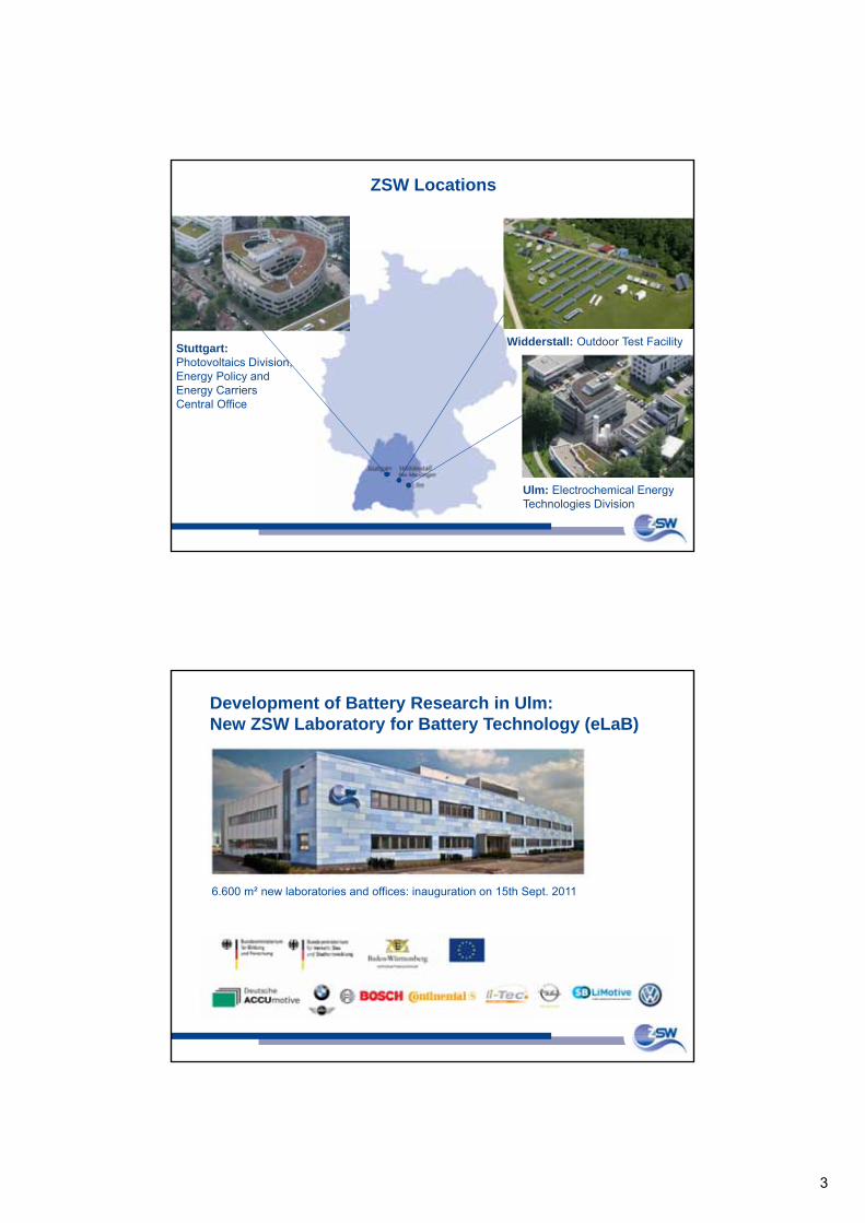
Stuttgart:Photovoltaics Division,Energy Policy and Energy CarriersCentral Office
Widderstall: Outdoor Test Facility
Ulm: Electrochemical Energy Technologies Division
ZSW Locations
6.600 m² new laboratories and offices: inauguration on 15th Sept. 2011
Development of Battery Research in Ulm:New ZSW Laboratory for Battery Technology (eLaB)
4
Contents
Introduction
Thin-Film Photovoltaics
Photovoltaic Cell Technologies
Accumulators
Battery Technology
Use Cases
Visions and Forecast
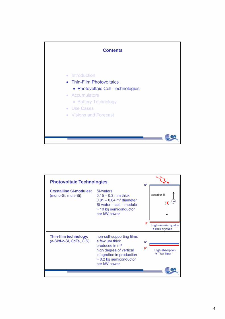
Photovoltaic Technologies
Crystalline Si-modules: Si-wafers(mono-Si, multi-Si) 0.15 – 0.3 mm thick
0.01 – 0.04 m² diameterSi-wafer – cell – module~ 10 kg semiconductorper kW power
Thin-film technology: non-self-supporting films (a-Si/tf-c-Si, CdTe, CIS) a few µm thick
produced in m²high degree of vertical integration in production~ 0.2 kg semiconductor per kW power
Absorber Si
n+
p+
-+
High material quality Bulk crystals
n+
p+
High absorption Thin films

5
Why Thin-film Solar Cells?
Low materials consumption Low energy consumption short energy payback time
- few process steps Direct fabrication of modules! Substrate sizes of up to 5.7 m2 possible (glass industry!)
- cost effective
- additional benefits: „nicer“, flexible, free choice of substrate (e.g. glass, metal, polymer, ...)
Crystalline silicon(mono-Si, multi-Si)
Thin film PV(a-Si/µc-Si, CdTe, CIS)
Thickness 150 µm – 300 µm
Thickness 3 µm – 5 µm
- thin
polycrystallinesemiconductors
Photovoltaic Materials
So
lar
cells
dyesolar cells
new concepts
silicon
organic cells
Multiband …
liquid electrolyte
solid electrolyte
CdTe
ChalkopyrideCIGSSe
III–V cells
thin-film
crystalline (wafer)monocrystalline
polycrystalline
Kesterite …
kristallin
amorphmikrokristallin
CdTe
chalcopyriteCIGSSe
amorphousmicrocrystalline
Thin Film
crystalline
“Work horse”
Advanced
R&D

6
Prof. Dr. M. Powalla / Seite 11
Quelle: http://upload.wikimedia.org/wikipedia/commons/7/74/PVeff%28rev100921%29.jpg
Prof. Dr. M. Powalla / Seite 12
Overview of Efficiencies
Photovoltaic MaterialLab.
cellPilot
production
Mass production
(module efficiency)
Monocrystalline Si 25 % 21 % 13 – 18 %
Polycrystalline Si 20 % 18 % 11 – 14 %
Amorphous a-Si/µcSi 13 % 8 – 11 % 7 – 10 %
Gallium-arsenide-basedmulti-junction cells (III/V)
42 % 26 % 22 %
Chalcopyrite (CIGS) 20 % 14 % 12 – 13 %
Cadmium telluride (CdTe) 17 % 12 % 10 – 11 %
Dye-sens. solar cells 11 % 3 – 5 %
Kesterite (CTZSS)
Organic cells
10 %
9 %

7
Photovoltaic Thin-Film Technology
Rückkontakt
Frontkontakt
Substrat
Encapsulation Glass, foil + polymer
Glass, foil + polymer
Substrate Configuration
Absorber / p/n
Back contact
Front contact
Substrate
Absorber / p/n structure
Light
Frontkontakt
Rückkontakt
Encapsulation
Substrat
Superstrate Configuration
Absorber / p/n
Front contact
Back contact
Substrate
Absorber / p/n strukture
Light
Basic Principle
ZnO
Light
Glass (1-4mm)
TCO
n
Ag
p
i
n
pi
µc-Si:H
a-Si:H 3µm
a-Si/µc-Si tandem cells(„Micromorph“)
Mo (0.5 µm)
ZnO:Al (1 µm)
CdS (0.05 µm)
Glass (3 mm)
CIGS (2 µm)
i-ZnO (0.05 µm)
p
n
4µm
CIGS solar cells: CuIn1-xGaxSe1-ySy
Light
CdTe solar cells: CdTe
Light
Glass (1-4mm)
TCO
CdS (0.1 µm)
CdTe (3-8 µm)
Metal
Basic Principle: Thin-film Modules on the Market

8
Upcoming New Thin-film Technologies
Organic solar cellDye-sensitized solar cell
FTO
TiO2 : Dye
glass
Electrolyte
Metal
glass
Light
ITO
PEDOT : PSS
glass
Organic absorber
Metal or TCO
Light
Highly absorbing thin-film gives name to technology
Transparent Conductive Oxide (TCO) for front contact
Production Depth
SG Si Si Wafer Si Cell Module
TF FabGlass,Raw materials
Module
Crystalline Silicon
Thin-film PV
All production steps in one line

9
Production Technology (State of the Art)
1. Substrate• window glass, no standard size• 120 cm x 60 cm mostly used, or TFT “standards”• flexible foils more or less exotic
2. Thin-Film Technology• contact layers (TCO and metal): sputter, CVD• semiconductor:
• batch: PECVD, CBD• inline: co-evaporation, CSS, PECVD
3. Interconnection of cells• laser and mechanical patterning
4. Module technology• glass/glass laminates with EVA• glue bus bars, junction box etc.
Basic Principle: In-line Coating
VacuumLoad lock
VacuumLoad lock
Heating Deposition
Sputter cathodes orevaporation sources
Cleanedglass
Coatedglass
Basic Principle: Scribing Laser scribing system Source: Forschungszentrum Jülich

10
Monolithically integrated thin-film module
P 1 P 2G 1 P 3G 2 P 1 P 2G 1 P 3G 2 Glass
MoCIGS
CdSi-ZnO
Zn:Al
xllC0
activearea
Example: ZSW-type CIGS Module
Interconnection of Single Cells to Modules
-
+
-
+
Module voltage is proportional to the number of series-connected cells.The current is proportional to the cell area (or „length“).
Voltage
Current

11
Flexible Substrates Open new Application Areas
Contents
Introduction
Thin-Film Photovoltaics
Photovoltaic Cell Technologies
Accumulators
Battery Technology
Use Cases
Visions and Forecast

12
Accumulators
Optimization of secondary batteries for various applications:
Traction Battery cycle stability
USV Battery floating battery
Mobility energy (energy density)
Hybrid electric vehicle(HEV) Battery power (power density)
Theoretical Limit of different sec. Battery Systems

13
Ragone Diagram
Discharging time = spec. energy / spec. power
Electrochemical Storage
Storage + converterin one system Li-ion Batteries
Storage + converterin separate systems e.g. Redox Flow Batteries

14
Redox-Flow-Batterye.g. Vanadium Redox Flow Battery
cell pump electrode (C)
Capacity (tank) and power (cell) can be separately dimensioned
Seasonal storage possible
By far the most interesting System: Lithium-Ion-BatterySpecifications for Storage Technology (Mobility)
Safetyalso by cockpit errorConsumer Battery: < 90 WhHybrid Vehicle: 1-2 kWhPlug-In HEV: 6 – 10 kWhBattery Vehicle : > 20 kWh
Costs< 300 €/kWh (system)
Energy DensityElectrical Range> 200 Wh/kg
Life Time>15 years or/and> 300,000 cycles HEV> 4,000 BEV
Operating Conditions-30°C through +50°C, quick loading
vibration, shock, crash
Power
> 100 kWel

15
Functional Principle of Lithium-Ion-Battery - Combination of two Insertion Electrodes -
negative electrode / anode(e.g. graphite)
positive electrode / cathode(e.g. LiCoO2)
charge discharge
LiC6 C6 + Li+ + e- 2 Li0.5CoO2 + Li+ + e- 2 LiCoO2
electrolyte(z.B. LiPF6 / EC-DEC)
New Cathode Materials
Cathode is a limitationLiCoO2 150 mAh/gGraphite 320 mAh/g
Cathode with higher capacityand lower costs needed
Capacity (Ah/kg)
Po
ten
tial
ag
ain
st L
i/Li+

16
New Cathode Materials
Layered structureLiCoO2, Li(Ni0,80Co0,15Al0,05)O2,
LiCo1/3Ni1/3Mn1/3O2
Spinel structureLiMn2O4, LiMn1.5Ni0.5O4
Olivine structureLiFePO4, LiMePO4
• Differences in Li+ diffusion• Differences in reaction mechanisms (phase transformation)• Differences in lattice stability in the delithiated state
Dependent on structure:
Comparison of Cathode Materials
MaterialPower density
Safety Stability Costsper Ah
Energy density
LCOLiCoO2
NCALiNi0,80Co0,15Al0,05O2
NMCLiNi0,33Mn0,33Co0,33O2
LMOLiMn2O4
LFPLiFePO4
Very good Very bad

17
New Anode Materials
• “zero” strain• No reaction with electrolite• Very long life-time• Safe
• High capacity• Big volume change• Nano composite
Capacity [Ah/kg]
Po
ten
tial
ag
ain
st L
i/Li+
Alternative Anode Materials- Nanodisperse or meso porose TiO2 -
within the stability window of electrolyte no solid electrolyte interface (SEI) formation high thermal stability high safety no lithium plating
low capacity and lower cell voltage suited for high power cells and ultra long cycling life “high energy supercapacitor”

18
Development Trends
Next generation of Li-Ion Batteries:
● High energy batteries (4C market)- high capacity anode and cathode materials- LiNi1/3Co1/3Mn1/3O2, LiNi1-xCoxO2
● High power batteries (Power Tools, HEV)- thin electrodes- Blend LiMn2O4 and LNC- LiMn2O4, LiFePO4
● Higher safety (Large batteries, HEV)- non flammable electrolytes, polymer electrolytes- safer cathode materials
● Cost reduction- replacement of cobalt and nickel
Battery Technology: Lithium-Ion-BatteryCylindrical
simple production (wrap) Firm body (40 bar) Defined opening pressure of
burst wave Safe leak tightness
+ High T-gradients in cell+ Bad packing density
Prismatic
Flat construction Good heat control Flexible dimensioning Simple battery stack
+ Difficult sealing+ Swelling at overpressure
Source: Varta
positive pole
negative pole
sealing gasket
Deckteil
Abstandhalter
Li-Verbindungen(cathode)
Grafitverbindungen(anode)
separator
overpressure valvedeflector

19
Production Steps for Li-Ion Batteries
Source: http://www.mpoweruk.com/battery_manufacturing.htm
- 38 -
Lithium-Ion Battery Systems: Safety Issues
Source: W. Praas, 2008
Thermally Stable Cathode Materials
No Activity at Surface of Anode
Cell Structure
Stable Separator
Non-inflammable Electrolyte
Integration in Vehicle
Battery Management

20
Contents
Introduction
Thin-Film Photovoltaics
Photovoltaic Cell Technologies
Accumulators
Battery Technology
Use Cases
Visions and Forecast
Requirements for Storage Systems
Cell 6 Ah 6 – 8 Ah 10 – 40 Ah > 40 Ah
Cell type cylindrical, prismatic prismatic prismatic, pouch
Cycle depth < 20% 50-70% 80-100%
Battery system Pb, Supercaps, Nickel/Metal hydride,
Lithium-IonLithium-Ion Lithium-Ion
Mild Hybrid Full HybridPlug-In Hybrid
BatteryE-Vehicle
Fuel CellE-Vehicle
Range Start / Stop Few km Up to 60 km 100 - 200 kmca. 500 km
Degree of Electrification 100%
H2
0 %

21
Dr. M. Powalla / Seite 41
Important: Degree of Self-Consumption of PV, Combination with E-Vehicle, Decentralized Storage in a Smart Grid
Source: EnBW, Kundenzeitschrift
area neededVehicle today (Bio diesel): 10,000 m2
H2- Vehicle (H2 from bio mass): 1,000 m2
H2- Vehicle (H2 from PV): ca. 60 m2
E- Vehicle (PV): < 20 m2
Grid-Connected PV with Storage System
SOL-ION-System (25 systems in Germany) : Storage capacity from 10 to 12 kWh (Li ion batteries),PV-Power from 2 to 5 kWp,Inverter from 3 to 8 kW
Grid
PV Generator
SystemManagement
BatteryInverter
=
-Load
bidirectional energy flow
Stability with fluctuating PV input and fast load change:Self consumption vs. - Battery size
- PV size 80 % possible - Grid feed-in tariff

22
Contents
Introduction
Thin-Film Photovoltaics
Photovoltaic Cell Technologies
Accumulators
Battery Technology
Use Cases
Visions and Forecast
Thin-Film PV:Cost Reduction Potential
Goal: 15 % – 18 % industrial module efficiency
- Standardization of processes and equipment- Understand correlations between preparation parameters
and material and interface characteristics- Develop multi-junction cells
New production processes (avoid expensive equipment)
Production costs from 2016 through 2025*
* Source: Strategic Research Agenda of EC (currently under revision)
a-Si/µc-Si CIS CdTe
< 0.5 €/Wp (@500 W/a) < 0.5 €/Wp < 0.4 €/Wp = 14 % = 16-17 % = 16 %

23
Materialien, Recycling
Skaleneffekte
Fertigungs-technologie (Zelle + Modul)
Lithium-Ion-Battery: Cost Reduction Potential
BCG 2009
McKinsey 2009
McKinsey 2009 AT Kearney 2009
Li‐Tec 2009
Li‐Tec 2009
Anderman 2009
Anderman 2009
Fraunhofer 2009/CARB 2007
Fraunhofer 2009/
CARB 2007
Fraunhofer 2009/CARB 2007Fraunhofer 2009/CARB 2007
BCG 2009
SBLimotive 2009
McKinsey 2009
McKinsey 2009
AT Kearney 2009
CARB 2007
CARB 2007
0
300
600
900
1200
1500
2005 2010 2015 2020 2025 2030 2035
$/kW
h
Target costs 300 $/kWhEV target costs: 300 $/kWh
Source: Schott, B., C. Günther und A. Jossen, Batterie-Roadmap 2020+, ZSW-Studie, April 2010
Consumer cells today: 250 $/kWh
Quelle: SB LiMotive
• Materials, Recycling• Production Scale• Production Technology
(cell and module)
Visions:PV
New design concepts towards 30 % efficiency
Modern flat glass coaters can coat 3 x 6 m² plates with a
45s cycle time (1,500 m²/h), 9 km² SLSG per year
Modern „Roll-to-Roll Coater“ (width 4 m, speed 144,000 m²/h)
500 km² foil (1 x Bremen) per year
Or: Can we print our PV modules the way we print newspapers?
Li-Ion Battery
Li-Ion Technology will be the choice for e-mobility
Improve area and costs, energy and power density, safety and life-
time at the same time
no dramatic change in production technology needed but
correlated R&D Material-Cell-System needed for 250Wh/kg/15y
Significant increase of range/cycling due to new battery concepts