Materials development for IFE systems - IAEA NA · Materials development for IFE systems Dr. Raquel...
65
Materials development for IFE systems Dr. Raquel González Arrabal [email protected] Instituto de fusión nuclear
Transcript of Materials development for IFE systems - IAEA NA · Materials development for IFE systems Dr. Raquel...

Materials development
for IFE systems
Dr. Raquel González Arrabal
Instituto de fusión nuclear
Raquel González Arrabal IAEA 18-20 March 2015
Outlook
• Motivation
• Plasma Facing Materials.
– New approach: nanostructured W
• Final optics
– Thermomechanical effects
– Atomistic effects:
• Defect production
• Effect on macroscopic properties
• Conclusions

Raquel González Arrabal IAEA 18-20 March 2015
Sketch of HiPER power plant
D. Garoz et al. Nucl. Fusion 53 (2013) 013010

Raquel González Arrabal IAEA 18-20 March 2015
Motivation
One of the main bottle neck for fusion to become a
reality is the lack of materials able to withstand
the harsh radiation environment:
•Thermal loads
•Atomistic damage

Raquel González Arrabal IAEA 18-20 March 2015
Radiation on PFM
Time
(s)
Deposit
ed
energy
(MJm-2)
Power
(MWm-
2)
Heat flux
paramet
er
(MJm-2s-
1/2)
Particl
e
energ
y
(eV)
Partic
le
flux
(m-2s-
1)
Diverto
r
steady
state
1000 - 15 - 1-30 <1024
ELM’s
VDEs
0.2×10⁻³
0.3
1
60
5×10³
2×10²
70 1-30
1-30
<1024
<1024
Direct
target
α-
particl
es
200×10-
9
0.03 1.5×10⁵ 70 2.1×10⁶
avg.
<1025
• Major hazards: the intense thermal loads (X-rays) and ions (He, H-
isotopes)
• Neutrons do not suppose a serious threat for PFM

Raquel González Arrabal IAEA 18-20 March 2015
Radiation on PFM

Raquel González Arrabal IAEA 18-20 March 2015
Exfoliation of metal
following high dose
irradiation [M. Rubel, trans.
On fus. Sci. and tech. 53 (2008)
459] He plasma induced nanostructure in W [S. Takamura et al. Plasma
and Fusion Res., 1, (2006) 051]

Raquel González Arrabal IAEA 18-20 March 2015
Renk et al. FST 61 (2012)
Pulsed He irradiation
Severe cracking at low dose
(1015 cm-2)
• This imposes a limit to the use of W, as low as 1015 He·cm-2 in IFE (tens of minutes of
operation).
It is necessary to develop appropriate materials
↔ to understand the microscopic mechanisms

Raquel González Arrabal IAEA 18-20 March 2015
PFM: state of the art research
Nowadays some strategies to overcome W limitations are being investigated:
1. Engineered 3D surfaces
• Reduce the thermal loads arriving to the PFM by increasing the surface
area while keeping the thermal conductivity high.
Pulsed He
irradiation
After1600 pulses no sign of voids,
bubbles or blisters are observed
W needles[T. J. Renk, et al. Fus. Sci.and Tech. 61 (2012)]
W foams[D. L. Youchison et al. Fus. Eng. and
Des. 82 (2007) 1854]

Raquel González Arrabal IAEA 18-20 March 2015
PFM: state of the art research
• Nanostructured materials: two approaches
ODS_W based materials
[T. Karabacak et al. J. Appl. Phys 94 (2003) 7723]La2O3 [M. A. Yar et al.
JNM 408 (2011) 129]
Nanostructured columnar materials

Raquel González Arrabal IAEA 18-20 March 2015
Nanostructured W
SEM image of W nanocolumns deposited on
Si.• Films deposited by sputtering
• Work was devoted to optimize
the deposition procedure to
achieve nanocolumnar
samples with low stress.
N. Gordillo et al., Appl. Surf. Sci. 316 (2014) 1–8

Raquel González Arrabal IAEA 18-20 March 2015
Nanostructured W
N. Gordillo et al., Appl. Surf. Sci. 316 (2014) 1–8

Raquel González Arrabal IAEA 18-20 March 2015
Coating morphology and microstructure
30 35 40 45 50 55 60 65 70 75 80 85 90
Si (110)
α-W(220)
α-W(211)
α-W(200)
Inte
nsity (
a.u
.)2Θ
α-W(110)
Polycrystalline → (110) preferentially oriented
Nanostructured W
N. Gordillo et al., Appl. Surf. Sci. 316 (2014) 1–8
Raquel González Arrabal IAEA 18-20 March 2015
Radiation-induced damage
nanoestructured materials
• How GBs affect radiation-induced defect
configuration?
• How GBs affect light species behavior?

Raquel González Arrabal IAEA 18-20 March 2015
How GBs affect radiation-induced
defect configuration?
G. Ackland, Science 327, 1587 (2010)

Raquel González Arrabal IAEA 18-20 March 2015
SEM image of W nanocolumns deposited on Si.
Aims:
•Investigate the effect of sample morphology → NW and CGW
•Investigate the effect of implantations conditions:
• Single implantation: HYDROGEN
• Sequential implantation: CARBON and HYDROGEN
• Implantations temperature: RT, 400ºC
•Implantation energies were selected to mimic as much as possible IFE
conditions
•The implantation dose was selected to be 5x1016 cm-2
Hydrogen behaviour

Raquel González Arrabal IAEA 18-20 March 2015
Fig. 2
NW-CHA400
300 nm
NW-pristine (a)
NW-C-H (c)
200 nm
NW-H (b)
NW-CH
200 nm
Nanocolumns under
irradiation
Nanocolumns are stable
R. Gonzalez-Arrabal et al. JNM 453 (2014) 287–295

Raquel González Arrabal IAEA 18-20 March 2015
Microstructure
30 40 50 60 70 80 90
α-W(220)
α-W(211)
α-W(200)
α-W(110)
CGW-Pristine
CGW-H
CGW-C-H
CGW-CH
CGW-C-H400
I (a
u)
2θ (º)30 35 40 45 50 55 60 65 70 75 80 85 90
α-W(220)
α-W(211)
α-W(200)
NW-C-H
NW-CH
NW-C-HA400
NW-Pristine
NW-H
I (a
u)
2θ (º)
α-W(110)
• No significant change in the state stress of the films→ Compressive
• No secondary phases in implanted samples.
R. Gonzalez-Arrabal et al. JNM 453 (2014) 287–295

Raquel González Arrabal IAEA 18-20 March 2015
H behaviour: single implantation
0 200 400 600 800 1000 1200
0,0
0,5
1,0
1,5
2,0
2,5
3,0
[H] (a
t.%
)
Depth (nm)
0,0
0,4
0,8
1,2
1,6
2,0 CGW-H
[H
] x10
-21 (
at/
cm
3)
0 200 400 600 800 1000 1200
0,0
0,5
1,0
1,5
2,0
2,5
3,0
[H] (a
t.%
)
Depth (nm)
0,0
0,4
0,8
1,2
1,6
2,0
[H
] x10
-21 (
at/cm
3)
NW-H
0
2
4
6
8
10
12
14
16
18
20
va
ca
ncie
s x
10
-23 (
cm
-3)
Ion
ra
nge
x 1
0-2
0 (
at/cm
3)
H Ion Range
0
1
2
3
4
5
6
H Vacancies
x100
0
2
4
6
8
10
12
14
16
18
20
Va
ca
ncie
s x
10
-23 (
cm
-3)
Ion
ra
nge
x 1
0-2
0 (
at/cm
3)
H Ion Range
0
1
2
3
4
5
6
H Vacancies
x100
surface surface
SRIM
calculations
RNRA
experimental
H1(N15,αγ)C12
NW CGW
R. Gonzalez-Arrabal et al. JNM 453 (2014) 287–295

Raquel González Arrabal IAEA 18-20 March 2015
H behaviour: sequential
implantation (C+H)
0
2
4
6
8
10
12
14
16
18
20
va
ca
ncie
s x
10
-23 (
cm
-3)
Ion
ra
nge
x 1
0-2
0 (
at/cm
3)
H Ion Range
C Ion Range
0
1
2
3
4
5
6
H Vacancies
C Vacancies
x100
0 200 400 600 800 1000 1200
0,0
0,5
1,0
1,5
2,0
2,5
3,0
[H] (a
t.%
)
Depth (nm)
0,0
0,4
0,8
1,2
1,6
2,0 CGW-H
CGW-C-H
[H
] x1
0-2
1 (
at/cm
3)
0 200 400 600 800 1000 1200
0,0
0,5
1,0
1,5
2,0
2,5
3,0
[H] (a
t.%
)
Depth (nm)
0,0
0,4
0,8
1,2
1,6
2,0
[H
] x1
0-2
1 (
at/cm
3)
NW-H
NW-C-H
0
2
4
6
8
10
12
14
16
18
20
va
ca
ncie
s x
10
-23 (
cm
-3)
Ion
ra
nge
x 1
0-2
0 (
at/cm
3)
H Ion Range
C Ion Range
0
1
2
3
4
5
6
H Vacancies
C Vacancies
x100
surface surface
SRIM
calculations
RNRA
experimental
H1(N15,αγ)C12
NW CGW
R. Gonzalez-Arrabal et al. JNM 453 (2014) 287–295

Raquel González Arrabal IAEA 18-20 March 2015
H behaviour: simultaneous
implantation (C+H)
0
2
4
6
8
10
12
14
16
18
20
Va
ca
ncie
s x
10
-23 (
cm
-3)
Ion r
an
ge
x 1
0*2
0 (
at/cm
3)
H Ion Range
C Ion Range
0
1
2
3
4
5
6
H Vacancies
C Vacancies
x100
0 200 400 600 800 1000 1200
0,0
0,5
1,0
1,5
2,0
2,5
3,0
[H] (a
t.%
)
Depth (nm)
0,0
0,4
0,8
1,2
1,6
2,0 CGW-C-H
CGW-CH
[H
] x1
0-2
1 (
at/cm
3)
0 200 400 600 800 1000 1200
0,0
0,5
1,0
1,5
2,0
2,5
3,0
[H] (a
t.%
)
Depth (nm)
0,0
0,4
0,8
1,2
1,6
2,0
[H
] x1
0-2
1 (
at/cm
3)
NW-C-H
NW-CH
0
2
4
6
8
10
12
14
16
18
20
Va
ca
ncie
s x
10
-23 (
cm
-3)
Ion
ra
nge
x 1
0-2
0 (
at/cm
3)
H Ion Range
C Ion Range
0
1
2
3
4
5
6
H Vacancies
C Vacancies
x100
surface surface
SRIM
calculations
RNRA
experimental
H1(N15,αγ)C12
NW CGW
R. Gonzalez-Arrabal et al. JNM 453 (2014) 287–295
Raquel González Arrabal IAEA 18-20 March 2015
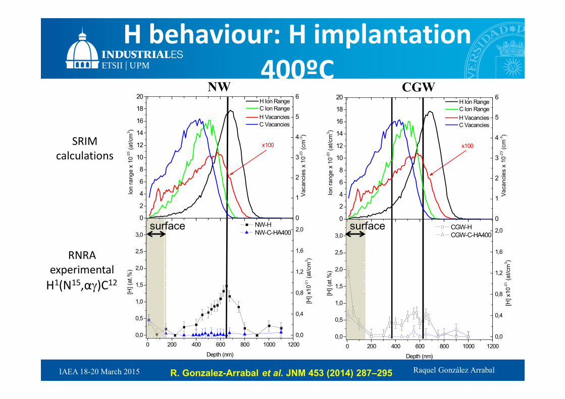
H behaviour: H implantation
400ºC
0 200 400 600 800 1000 1200
0,0
0,5
1,0
1,5
2,0
2,5
3,0
[H] (a
t.%
)
Depth (nm)
0,0
0,4
0,8
1,2
1,6
2,0 CGW-H
CGW-C-HA400
[H
] x10
-21 (
at/cm
3)
0 200 400 600 800 1000 1200
0,0
0,5
1,0
1,5
2,0
2,5
3,0
[H] (a
t.%
)
Depth (nm)
0,0
0,4
0,8
1,2
1,6
2,0
[H
] x1
0-2
1 (
at/cm
3)
NW-H
NW-C-HA400
0
2
4
6
8
10
12
14
16
18
20
Vacan
cie
s x
10
-23 (
cm
-3)
Ion
ra
ng
e x
10
-20 (
at/cm
3)
H Ion Range
C Ion Range
0
1
2
3
4
5
6
H Vacancies
C Vacancies
x100
0
2
4
6
8
10
12
14
16
18
20
Va
ca
ncie
s x
10
-23 (
cm
-3)
Ion
ra
nge
x 1
0-2
0 (
at/cm
3)
H Ion Range
C Ion Range
0
1
2
3
4
5
6
H Vacancies
C Vacancies
x100
surface surface
SRIM
calculations
RNRA
experimental
H1(N15,αγ)C12
NW CGW
R. Gonzalez-Arrabal et al. JNM 453 (2014) 287–295

Raquel González Arrabal IAEA 18-20 March 2015
H behaviour
0
2
4
6
8
10
12
14
16
18
20
Va
ca
ncie
s x
10
-23 (
cm
-3)
Ion
ra
ng
e x
10
-20 (
at/cm
3)
H Ion Range
C Ion Range
0
1
2
3
4
5
6
H Vacancies
C Vacancies
x100
0 200 400 600 800 1000 1200
0,0
0,5
1,0
1,5
2,0
2,5
3,0
[H] (a
t.%
)
Depth (nm)
0,0
0,4
0,8
1,2
1,6
2,0 CGW-H
CGW-C-H
CGW-CH
CGW-C-HA400
[H
] x10
-21 (
at/cm
3)
0 200 400 600 800 1000 1200
0,0
0,5
1,0
1,5
2,0
2,5
3,0
[H] (a
t.%
)
Depth (nm)
0,0
0,4
0,8
1,2
1,6
2,0
[H
] x1
0-2
1 (
at/cm
3)
NW-H
NW-C-H
NW-CH
NW-C-HA400
0
2
4
6
8
10
12
14
16
18
20
Va
ca
ncie
s x
10
-23 (
cm
-3)
Ion
ra
nge
x 1
0-2
0 (
at/cm
3)
H Ion Range
C Ion Range
0
1
2
3
4
5
6
H Vacancies
C Vacancies
x100
surface surface
SRIM
calculations
RNRA
experimental
H1(N15,αγ)C12
NW CGW
R. Gonzalez-Arrabal et al. JNM 453 (2014) 287–295

Raquel González Arrabal IAEA 18-20 March 2015
• W(112)/W(110)
semicoherente
interface.
• Vacancies and H locate
preferentially at the
GBs.
• Lower migration
energies than in the
bulk.
H behaviour: DFT
C. Pascual-Gonzalez et al. to be published

Raquel González Arrabal IAEA 18-20 March 2015
• GBs are trapping sites for
hydrogen.
• The hydrogen diffusivity
for NW lower than for
CGW and dependent on
the H concetration.
• H2 do not form
H behaviour: MD
P. Piaggi et al. JNM 458 (2015) 233–239

Raquel González Arrabal IAEA 18-20 March 2015
Code MMonCa (open source)
www.materials.imdea.org/MMonCa
Martin-Bragado et al. Computer Physics Communications 184 (2013) 2703
Physics in the parametrization
Rivera et al. NIMB 303 (2013) 81
Valles et al. JNM 457 (2015) 80
Object Migration
V Yes
Vn Yes
I Yes
In Yes
He Yes
Hen Yes
HenVm No
HenIm No
He behaviour: OKMC

Raquel González Arrabal IAEA 18-20 March 2015
Boundary conditions
NanocrystalPolycrystal
V I He
Y X
Z
He
100 nm
200 n
m
Y X
Z
He
100 nm
20
0 n
m
G. Valles et al. JNM 457 (2015) 80-87
Raquel González Arrabal IAEA 18-20 March 2015
X
V
I
He
Y
Z
X
V
I
He
Y
Z
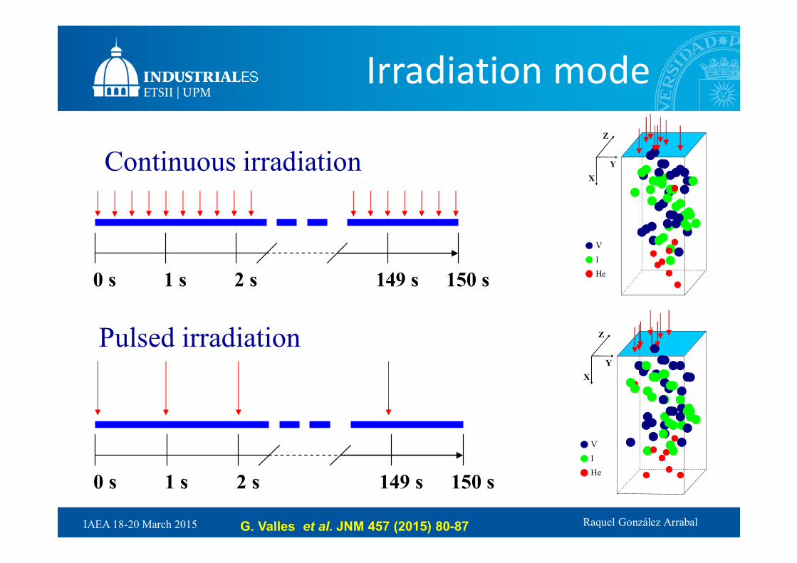
0 s 1 s 2 s 149 s 150 s
0 s 1 s 2 s 149 s 150 s
Continuous irradiation
Pulsed irradiation
Irradiation mode
G. Valles et al. JNM 457 (2015) 80-87

Raquel González Arrabal IAEA 18-20 March 2015
He (10 keV) retention in bulk
tungsten
0 5 10 15 20 25 30
0.1
0.2
0.3
0.4
0.5
0.6
0.7
0.8
Re
tain
ed H
e fra
ctio
n
Number of pulses
Polycrystal
Nanocrystal
0 1x10¹⁴
2x10¹⁴
3x10¹⁴
1100 K
Pulsed
Continuous
Continuous
Dose (cm-2)
Pulsed
0 5 10 15 20 25 30
0.1
0.2
0.3
0.4
0.5
0.6
0.7
0.8
Re
tain
ed H
e fra
ctio
n
Number of pulses
Polycrystal
Nanocrystal
0 1x10¹⁴
2x10¹⁴
3x10¹⁴
300 K
Pulsed
Continuous
Continuous
Dose (cm-2)
Pulsed
G. Valles et al. JNM 457 (2015) 80-87

Raquel González Arrabal IAEA 18-20 March 2015
Conclusions
• Nanostructure morphology is preserved after implantation.
• H and He behavior in NW is dominated by GBs.
• Synergetic effects have a large influence on the H retention in
CGW samples but do not in NW samples .
• NW seems to be very promising to work under radiation
environments. Further work to characterize the material behavior
under more realistic conditions

Raquel González Arrabal IAEA 18-20 March 2015
Sketch of HiPER power plant
D. Garoz et al. Nucl. Fusion 53 (2013) 013010

Raquel González Arrabal IAEA 18-20 March 2015
3Final optics• Ions
• Neutrons (full ion mitigation)
• Partial ion mitigation (swift heavy ions)
• Multi-scale modeling

Raquel González Arrabal IAEA 18-20 March 2015
HiPER 4a HiPER 4b (Power plant)
EXPERIMENTAL PROTOTYPE DEMO
Description Bunch mode Relaxed operation
Pre-commercialpower plant
Operation Bunches of 100 shots, max. 5 DT
explosions
Continuous (24/7)
Continuous (24/7)
Yield (MJ) <20 >20 >100
Rep. rate (Hz)
1-10 1-10 10-20
Power (GWt)
- <0.5 1-3
T cycle No Yes Yes
Blanket No Yes Yes
• Direct targets for shock ignition
• Evacuated dry wall chamber
Garoz et al. Nucl. Fusion 53 (2013) 013010
Raquel González Arrabal IAEA 18-20 March 2015
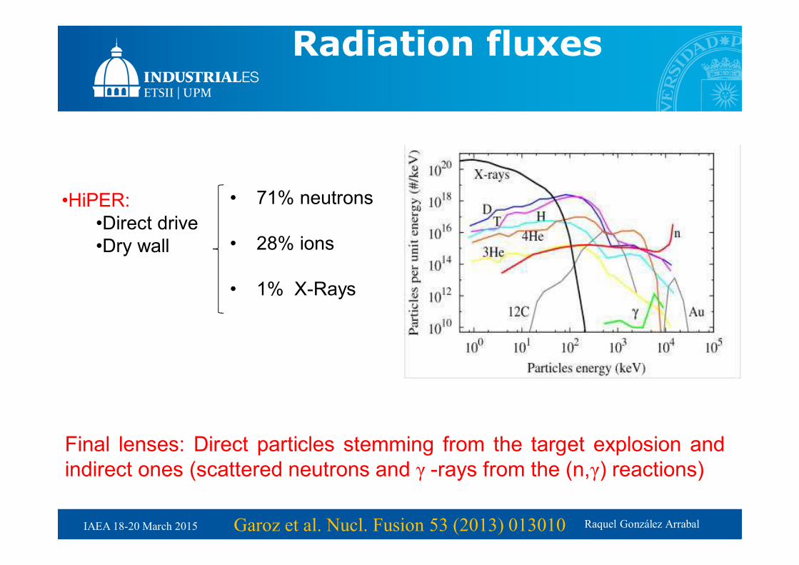
Radiation fluxes
•HiPER:
•Direct drive
•Dry wall
• 71% neutrons
• 28% ions
• 1% X-Rays
Final lenses: Direct particles stemming from the target explosion and
indirect ones (scattered neutrons and γ -rays from the (n,γ) reactions)
Garoz et al. Nucl. Fusion 53 (2013) 013010

Raquel González Arrabal IAEA 18-20 March 2015
Radiation
The energy density deposited by ions in HiPER prototype and demo is so
high that it would drive to temperature enhancements higher than the Silica
melting point→ For the lenses to work ions must be somehow mitigated
HiPER
<E>(MeV)
Pulse width(ns)
Pen-depth(mm)
ED in exp.(J/cm3)
ED prot-(J/cm3)
ED demo(J/cm3)
Burnt products
(4He)2.1 400 6.4 492.0 3788.48 1230.03
Debris ions (D)
0.15 2200 1.4 2549.08 19627.93 6372.7
X-rays 0.007 0.17 few103 33.91 261.11 84.78
Neutrons 12.4 60 - 0.018 0.142 0.046
Indirect gammas
- »60 - 0.007 0.051 0.017
Garoz et al. Nucl. Fusion 53 (2013) 013010

Raquel González Arrabal IAEA 18-20 March 2015
Thermomechanical response calculations
•The finite element solver CODE ASTER is used
•Lenses are considered to have a cylindrical geometry.
•To achieve a detailed estimation of the temperature gradients and local
stresses, the mesh is refined with small elements of 100 nm.
•For temperature calculation, the lens surfaces are considered to emit
radiation and the surrounding temperature is supposed to be constant.Considerations:
•X-rays (even when very penetrating up to the
cm range) deposit almost all their energy in
the first few microns (<10 µm) near inner
surface.
•Neutrons and gammas homogeneously
deliver their energy along practically the
whole lens volume.Garoz et al. Nucl. Fusion 53 (2013) 013010

Raquel González Arrabal IAEA 18-20 March 2015
Steady-state operation
•When working in continuous mode, the average lens
temperature increases if the energy deposited during each pulse
is higher than that radiated by the lenses surface.
•Steady-state is reached when the deposited energy and the
radiated during one pulse are equal.
•HiPER prototype: 32.000 pulses
•HiPER demo: 25.000 pulses (~40 min- after the first shot)
•LIFE2: 18.000 pulses
Garoz et al. Nucl. Fusion 53 (2013) 013010
Raquel González Arrabal IAEA 18-20 March 2015
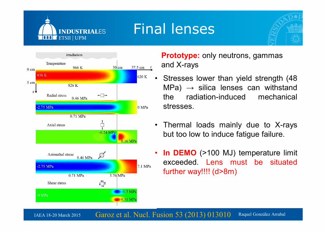
Steady-state operations (50 MJ)
Prototype: only neutrons, gammas
and X-rays
• Stresses lower than yield strength (48
MPa) → silica lenses can withstand
the radiation-induced mechanical
stresses.
• Thermal loads mainly due to X-rays
but too low to induce fatigue failure.
• In DEMO (>100 MJ) temperature limit
exceeded. Lens must be situated
further way!!!! (d>8m)
Garoz et al. Nucl. Fusion 53 (2013) 013010
Final lenses

Raquel González Arrabal IAEA 18-20 March 2015
• Power plant start up
• Focal length changes 4 cm from cold
to hot regimes.
• Pre-heating needed.
• The temperature profile induces
aberrations.
Garoz et al. Nucl. Fusion 53 (2013) 013010
Final lenses

Raquel González Arrabal IAEA 18-20 March 2015
Absorption at 3ω wavelength
(350nm):
Marshall et al. J. Non-Crystalline Solids. 212, 59 (1997)
ODC
245 nm
E’
213 nm
Neutron
Flux
γ-rays
DoseThermal
annealing
Atomistic damage: Color center formation
Radiation-induced defects can substantially modify the lens optical
properties. In particular the lens absorption.

Raquel González Arrabal IAEA 18-20 March 2015
109
1010
1011
1012
1013
1014
1015
0 1 2 3 4 5
Def
ect c
once
ntra
tion
(cm
-3)
Pulses
ODC
E’
10 Hz1 Hz
0.1 Hz
Color center evolution based on
Marshall´s model
g-dose is too low to promote
effective ODC-E´conversion
)(λLNσ=α(λ) ii
i
i∑2
2
1
1)
)(∆
λ)(λ+
=(λL
i
i
i
λ
−
with
,
with
Saturation in intensity value after
1000 pulses→ limits the lens
absorption
Garoz et al. Nucl. Fusion 53 (2013) 013010

Raquel González Arrabal IAEA 18-20 March 2015
Optical absorption
Remember: the lens optical transparency in the 350 nm region should be
as high as possible to minimize laser power loses.( )( )dλα=A −− exp1
5% is a kind of upper limit to efficiently achieve ignition
•The optical absorption at steady state operation for HiPER prototype and
is bellow 5%.
•At low temperatures A is quite high.
Garoz et al. Nucl. Fusion 53 (2013) 013010

Raquel González Arrabal IAEA 18-20 March 2015
,
… again, during start up the lenses become
dark unless preheated
Garoz et al. Nucl. Fusion 53 (2013) 013010
Optical absorption

Raquel González Arrabal IAEA 18-20 March 2015
To operate under pre-commercial
power plant conditions (150 MJ
@ 10 Hz):
Smooth temperature only
possible by means of a heat
transfer fluid.
A.R. Páramo et al. Nucl. Fusion
54 (2014) 123019

Raquel González Arrabal IAEA 18-20 March 2015
• Ions must be mitigated
• To anneal out color centers high temperature is needed
• To avoid aberrations and start-up problems, a temperature control
system based on fluid flow is needed
• Pre-commercial conditions require to position the lenses at large
distance (16 m conservative)
Raquel González Arrabal IAEA 18-20 March 2015
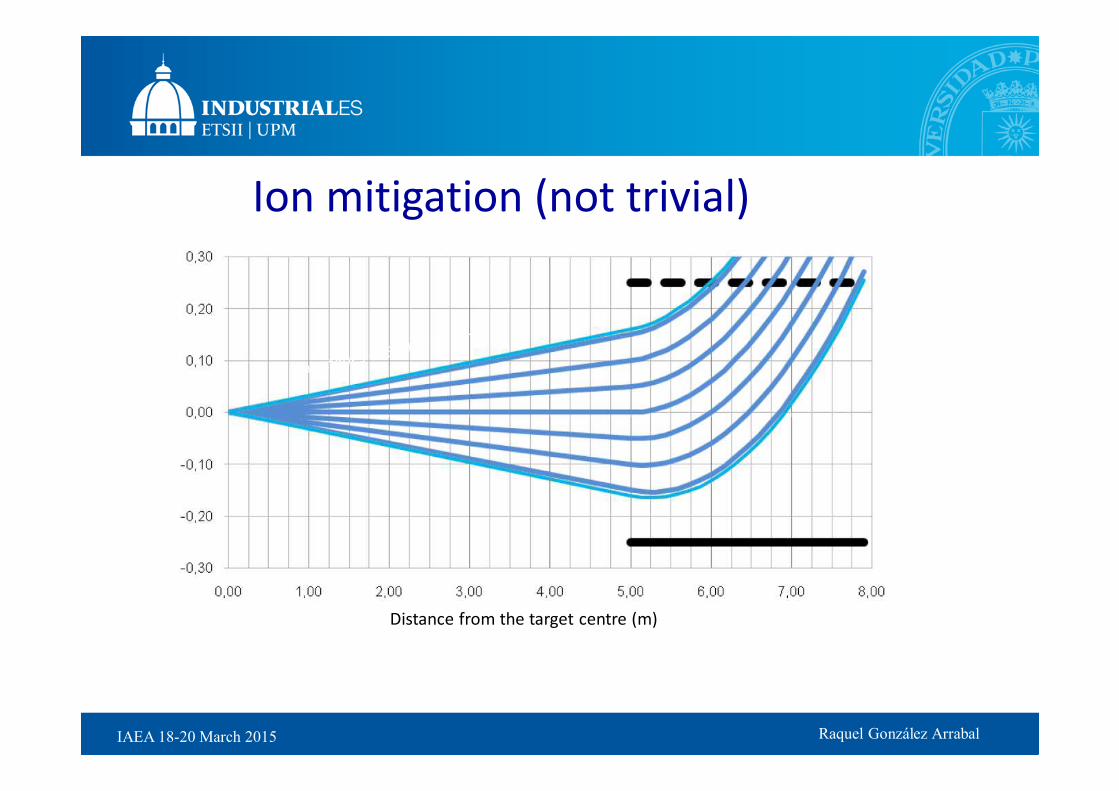
Distance from the target centre (m)
Ion mitigation (not trivial)
B. Rus

Raquel González Arrabal IAEA 18-20 March 2015
LASNEX
J. Perkins
100
101
102
103
104
105
109
1010
1011
1012
1013
1014
1015
1016
1017
1018
1019
Au debris
12C debris
4He debris
3He debris
H debris
T debris
D debris
4He BP
3He BP
H BP
T BP
D BP
n BP
gamma BP
Ion e
nerg
y d
istr
ibution (
ions/k
eV
)
Energy (keV)
Low yield (154 MJ) direct drive
• Neutrons ~70%, Ions ~30%, X-rays ~1%

Raquel González Arrabal IAEA 18-20 March 2015
Partial mitigation of ions might be not enough
• Electronic sputtering
• Nano-crater
• Nano-track
• Severe modification of properties
• Defect formation

Raquel González Arrabal IAEA 18-20 March 2015
Swift ion-
induced
electronic
sputtering
might
erode the
lenses
A. Rivera et al. in preparation

Raquel González Arrabal IAEA 18-20 March 2015
Ion tracks
nano-tracks
Raquel González Arrabal IAEA 18-20 March 2015
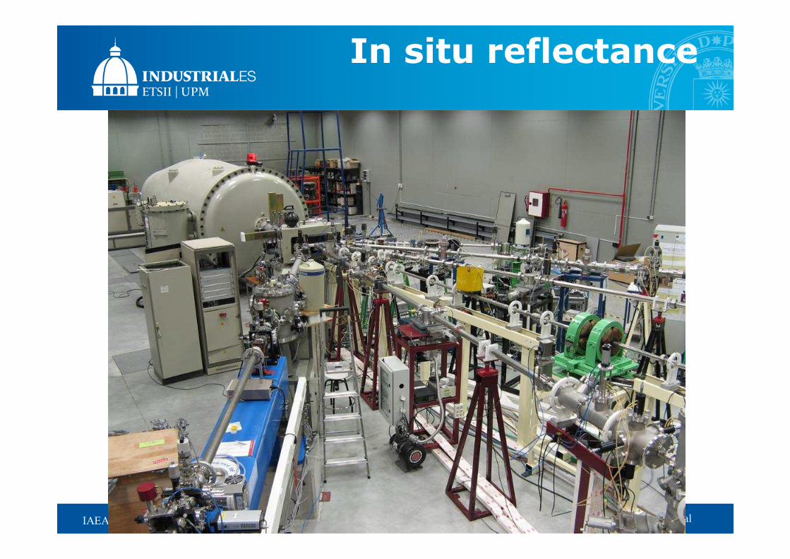
In situ reflectance

Raquel González Arrabal IAEA 18-20 March 2015
In situ reflectance
5-6 mm
Ion beam ≈ 6x6 mm2Sample at ≈15º
2 mirrors
inside chamber
( ) ( )ti θn=θn sinsin 21
RTrR −== 1,2
Snell’s law
Fresnel
coefficients
Reflectance
Refractive
index
θi θi
1
2
θt
21
21
nn
nnrrr ps
+
−===
Olivares et al. in preparation
Raquel González Arrabal IAEA 18-20 March 2015Olivares et al. in preparation
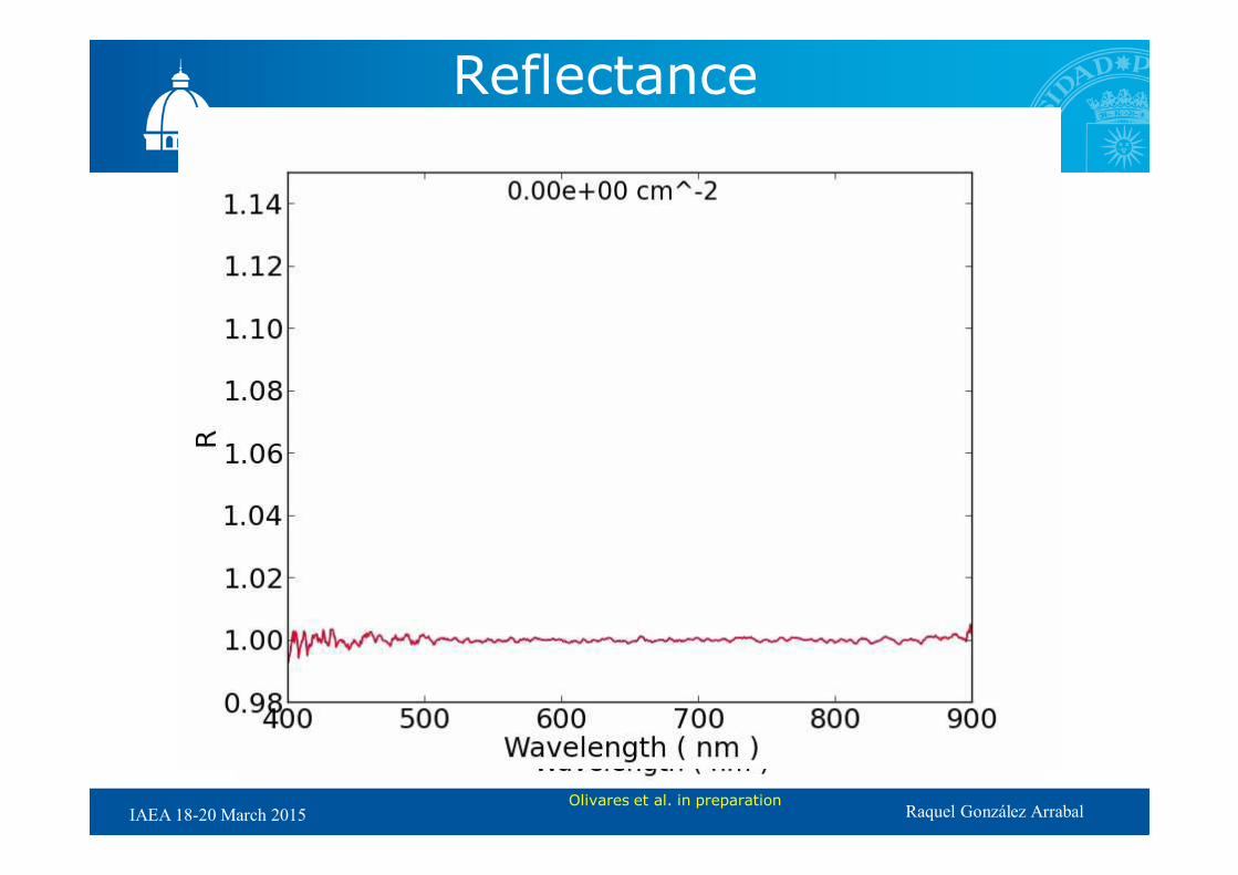
Reflectance measurements

Raquel González Arrabal IAEA 18-20 March 2015
Reflectance measurements
400 500 600 700 800 900
0,035
0,040
0,045
0,050
1e14
2e14
3e14
1e13
Re
flecta
nce
Wavelength (nm)
Quartz - Br 5 MeV
at/cm2
0
3e13
silica
400 500 600 700 800 900
0,034
0,036
0,038
0,040
1 e14
2 e13
1e13
3e12
1e12
virgin
Re
fle
cta
nce
Wavelength (nm)
silica - Br 5 MeV at/cm2
Olivares et al. in preparation

Raquel González Arrabal IAEA 18-20 March 2015
• Ion irradiation strongly
affects the material
• Density change
• Refractive index
• Defects
• Network structure
• Electronic sputtering
(surface)
Rivera et al. under consideration PRL

Raquel González Arrabal IAEA 18-20 March 2015
0 5 10 15 20 25 300
2
4
6
8
10
Br-reflectance (< 0.1 MeV/amu)
Br-reflectance (0.1-0.5 MeV/amu)
F-reflectance (0.3 MeV/amu)
SAXS (0.1-1.0 MeV/amu) [*]
FTIR (4-6 MeV/amu) [*]
SAXS (5-11 MeV/amu) [*]
Tra
ck r
adiu
s,
R (
nm
)
Electronic stopping power, Se (keV/nm)
MD (a = 3.5 nm)
MD (a = 4.0 nm)
MD (a = 4.5 nm)
MD (a = 5.0 nm)
θi θi
1
2
θt
Vacuum
Sample

Raquel González Arrabal IAEA 18-20 March 2015
• The tracks can have detrimental effects on lenses
• Right now, assessing this point
• On the other hand, we can control the optical properties of
the materials with the induced nano-tracks
www.denim.upm.es

Raquel González Arrabal IAEA 18-20 March 2015
Steady-state operation
•We have to keep on working hard to:
•Develop more radiation resistant materials
•Understand the underlying mechanism in the
radiation-induced damage.
Garoz et al. Nucl. Fusion 53 (2013) 013010

Raquel González Arrabal IAEA 18-20 March 2015 www.denim.upm.es
Materials group at the IFN
Prof. José Manuel Perlado
Dra. Emma del Río
Dra. Raquel Gonzalez-Arrabal
Dr. Carlo Guerrero
Dra. Nuria Gordillo
Dr. Antonio Rivera
Dr. Ovidio Peña
David Cereceda
Miguel Panizo
Jose Antonio santiago
Gonzalo Valles
Alejandro Prada
Miguel Panizo-Laiz

Raquel González Arrabal IAEA 18-20 March 2015
He and vacancies
He by itself acts as nucleation site for vacancies in bulk
tungsten (in both polycrystal and nanocrystal)
0 20 40 60 80 100 120 140
0.0
0.2
0.4
0.6
0.8
1.0
Polycrystal
Nanocrystal
Number of pulses
Re
tein
ed
He
fra
ctio
n
0.0 5.0x10¹⁴
1.0x10¹⁵
1.5x10¹⁵
Dose (cm-2)
Helium
0 20 40 60 80 100 120 140
0.00
0.04
0.08
0.12
0.16
0.20
Polycrystal
Nanocrystal
Polycrystal (no He)
Nanocrystal (no He)
Re
ma
inin
g v
aca
ncy fra
ctio
n
Number of pulses
0.0 5.0x10¹⁴
1.0x10¹⁵
1.5x10¹⁵
Dose (cm-2)
Vacancies

Raquel González Arrabal IAEA 18-20 March 2015
Radiation fluxes: HiPER
•The neutron flux and neutron and g-ray doses absorbed by the silica
lenses in HiPER are accurately calculated as a function of time with
MCNPX.
•The reactor geometry is designed with CATIA and converted with MCAM
into a valid geometrical input for MCNPX. Mean free path for calculation
are obtained from the ENDF-VII data base
•Final lenses are simultaneously subjected to neutron and gamma
radiation pulses.
Garoz et al. Nucl. Fusion 53 (2013) 013010
Raquel González Arrabal IAEA 18-20 March 2015
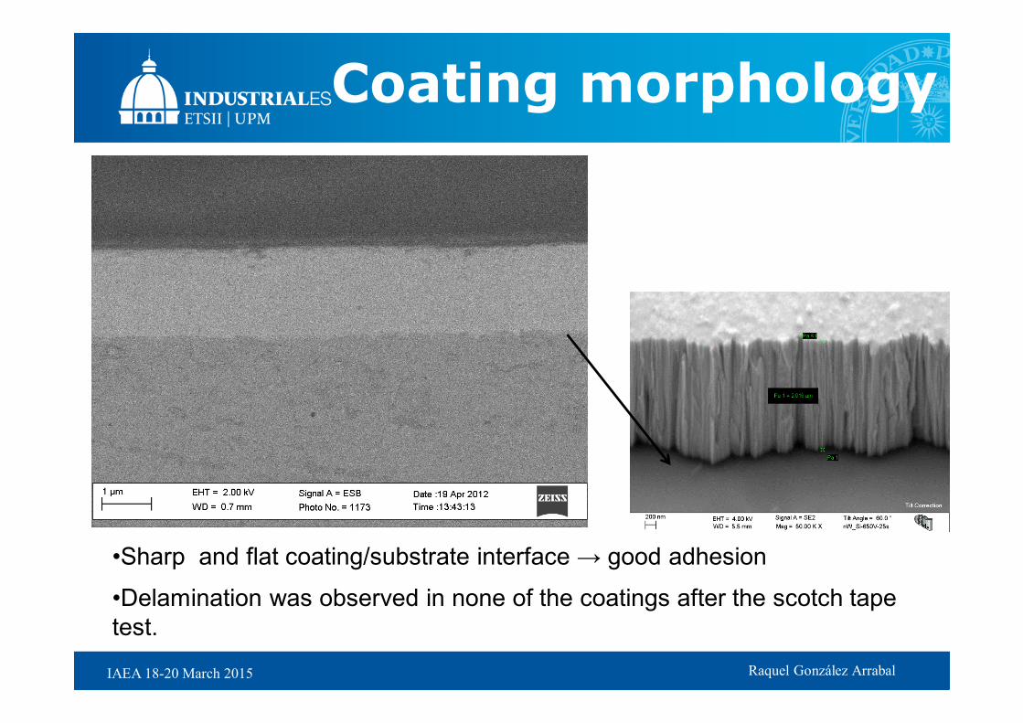
Coating morphology
•Sharp and flat coating/substrate interface → good adhesion
•Delamination was observed in none of the coatings after the scotch tape
test.
Raquel González Arrabal IAEA 18-20 March 2015
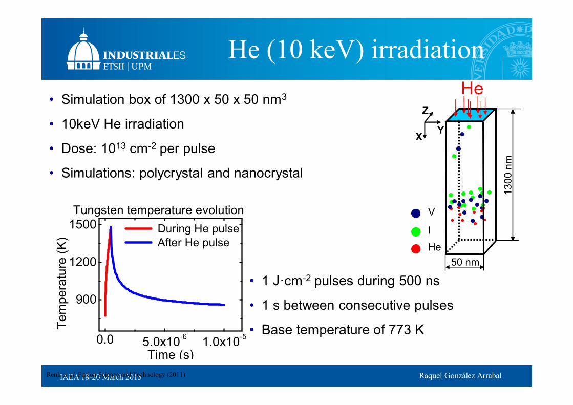
• Simulation box of 1300 x 50 x 50 nm3
• 10keV He irradiation
• Dose: 1013 cm-2 per pulse
• Simulations: polycrystal and nanocrystal
He (10 keV) irradiation
• 1 J·cm-2 pulses during 500 ns
• 1 s between consecutive pulses
• Base temperature of 773 K
V
I
He
Z
He
Y X
50 nm
13
00
nm
0.0 5.0x10⁻⁶
1.0x10⁻⁵
900
1200
1500 During He pulse
After He pulse
Te
mp
era
ture
(K
)
Time (s)
Tungsten temperature evolution
Renk et al. Fusion Science and Technology (2011)

Raquel González Arrabal IAEA 18-20 March 2015
Hot cylinder
Radius 3-5 nmThermal evolution
Radius 14.3 nm
Thermal bath, 300 K
Rescaled every 5 fs
Box with or without PBC, 30×30×14 nm3 ~8.5e5 atoms
Feuston-Garofalini potential
Code MDCASK 256-512 processors @CESVIMA (UPM)

Raquel González Arrabal IAEA 18-20 March 2015
005 ps
010 ps
100 ps
Rivera et al. under consideration PRL