
Materials Compensation Technique for Remote Field ... · Materials Compensation Technique for...
21
Materials Compensation Technique for Remote Field Technology users Ed Brain Marketing Manager Russell NDE Systems Inc. www.russelltech.com 1
Transcript of Materials Compensation Technique for Remote Field ... · Materials Compensation Technique for...

Materials Compensation Technique for Remote Field Technology users
Ed Brain
Marketing Manager
Russell NDE Systems Inc.
www.russelltech.com1

Agenda
• Background
• RFT defect sizing
• Material compensation in RFT inspection
• Software program description
• Experimental verification of material compensation
• Summary2

Background
• Calibration tubes are required in RFT inspection of carbon steel tubes.
• Calibration tubes are not always identical to the tubes to be inspected. Differences include wall thickness, electric and magnetic properties.
3
Background (continued)
• Even tubes within one bundle are different from each other in wall thickness and material properties.
• It is not practical to prepare a series of calibration tubes that match those in the bundle.
4

Background (continued)
• It is inconvenient to change operating frequency when testing a large tube bundle.
Material compensation (Mat’l Comp) is proposed to take into account differences in both tube wall thickness and material properties before defects are sized.
5
RFT defect sizing
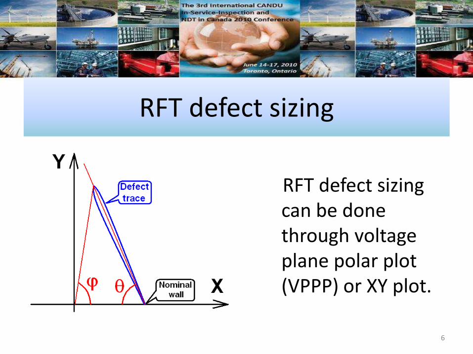
RFT defect sizing can be done through voltage plane polar plot (VPPP) or XY plot.
6

RFT defect sizing (continued)
Typical calibration curves using RFT VPPP and XY plot.
7
Material compensation in RFT inspection
• Material compensation involves calibration defect trace rotation and phase spread adjustment according to RFT theory.
• The amount of trace rotation and phase spread is determined primarily by the difference of nominal phase reading between the calibration and actual samples.
8
Material compensation in RFT inspection (continued)
• Free air phase reading is also needed for material compensation, which is a one-time measurement before tube bundle inspection.
9
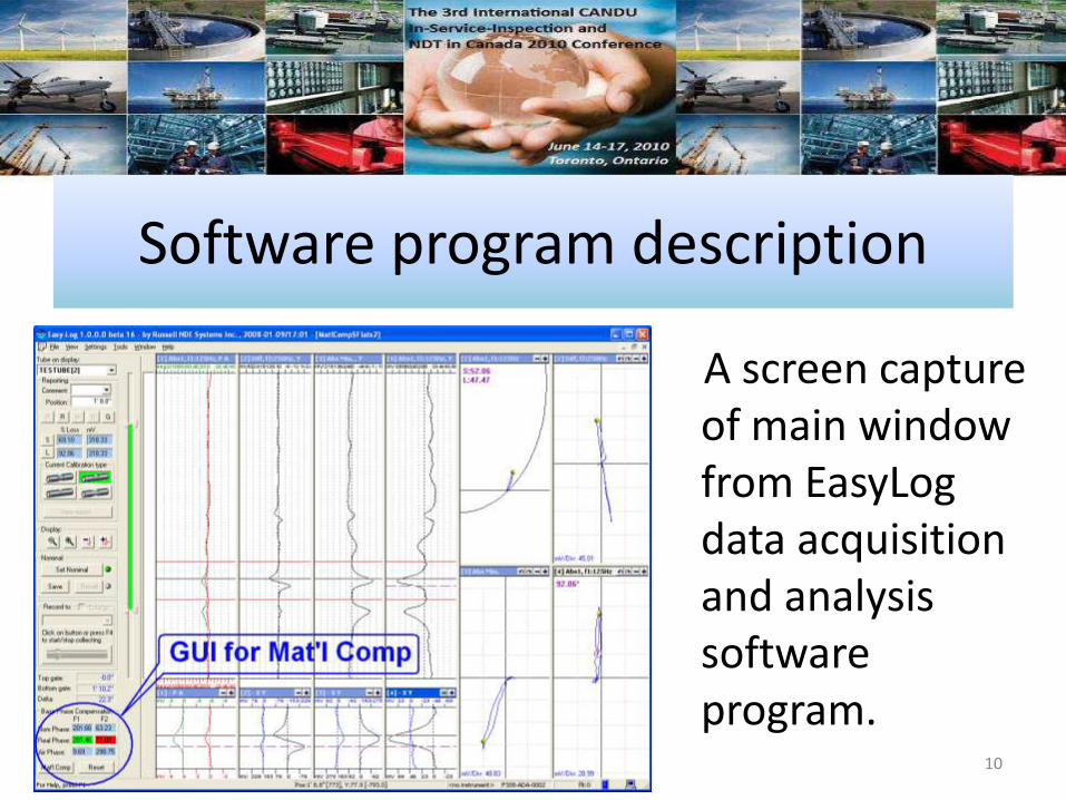
Software program description
A screen capture of main window from EasyLog data acquisition and analysis software program.
10

Experimental verificationof material compensation
Short flat defects
• Cal tubef0.75" x 0.083", SA-179
30% and 60% deep flats
• Test tube
f0.75" x 0.085", SA-214
25%, 50% and 75% deep flats 11

Experimental verificationof material compensation (continued)
Short flat defects• Before Mat’l Comp is applied
25% 6%50% 35%75% 61%
• After Mat’l Comp is applied25% 25%50% 52%75% 75% 12
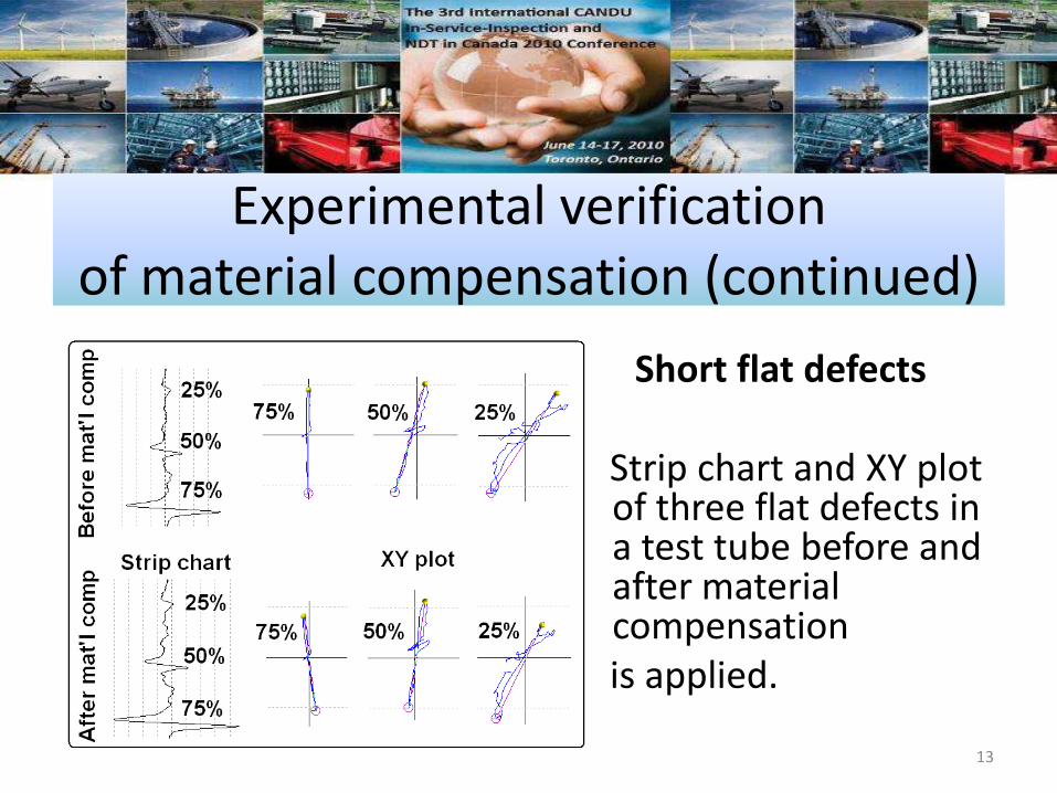
Experimental verificationof material compensation (continued)
Short flat defects
Strip chart and XY plot of three flat defects in a test tube before and after material compensation is applied.
13

Experimental verificationof material compensation (continued)
Short full circumferential grooves
• Cal tube
f0.75" x 0.087", SA-214
20% and 40% deep
• Test tube
f0.75" x 0.109", SA-214
20% and 40% deep14

Experimental verificationof material compensation (continued)
Short full circumferential grooves
• Before Mat’l Comp is applied20% can not be sized
40% 35%
• After Mat’l Comp is applied20% 9%
40% 47%15

Experimental verificationof material compensation (continued)
Flat bottom holes
• Cal tube
f0.75" x 0.087", SA-214
53%, 75% and 100% deep
• Test tube
f0.75" x 0.115", SA-214
50%, 75% and 100% deep16

Experimental verificationof material compensation (continued)
Flat bottom holes• Before Mat’l Comp is applied
50% 60%75% 78%100% 96%
• Mat’l Comp is not applied
Mat’l Comp is not needed since the difference in wall thickness happens to be self-compensated by material property difference.
17

Summary
• Mat’l Comp has been verified through several types of defects in test tubes with differences in wall thickness and/or material properties.
• Mat’l Comp has been implemented in EasyLog software program with capabilities of both data acquisition and analysis.
18
References and Useful Links
• Mackintosh, D.D., D.L. Atherton and S. P. Sullivan, Materials Evaluation, Vol. 51, No. 3, April, 1993, pp.492-495.
• www.physics.queensu.ca/~amg/remote_field.html
19

Ed BrainMarketing Manager
Russell NDE Systems Inc.www.russelltech.com
Questions?
20

Ed BrainMarketing Manager
Russell NDE Systems Inc.www.russelltech.com
Thank You!
21


![Index [dge.carnegiescience.edu] · 2016-12-22 · Index Multicluster blocks technique, 146 Multidimensional ordination technique, 22-23 Multiple observations, remote sensing, 183](https://static.fdocuments.us/doc/165x107/5e8ecef5ab63bf00b4341933/index-dge-2016-12-22-index-multicluster-blocks-technique-146-multidimensional.jpg)
