
MATERIALS AND FABRICATION - pudn.comread.pudn.com/downloads105/ebook/431660/Axial Flux Permanent...
45
MATERIALS AND FABRICATION Most laminated cores for stators of AFPM brushless machines are made of nonoriented (isotropic) silicon steel ribbons with standard thickness from 0.12 to 0.64 mm. Nonoriented steels are Fe-Si alloys with a random orientation of crystal cubes. Magnetic properties are practically the same in any direction in the plane of the sheet or ribbon. A secondary recrystallization process is not needed and high temperature annealing is not essential. Nonoriented grades contain between 0.5% and 3.25% Si with up to 0.5% Al addition to increase the resistivity and lower the temperature of the primary recrystallization. Nonoriented electrical steels are available as both fully processed and semi- processed products. Fully processed nonoriented electrical steels are com- pletely processed by the steel manufacturer, ready for use without any ad- ditional processing required to achieve the desired magnetic quality. Semi- processed nonoriented electrotechnical steels are those which have not been given the full annealing treatment by the steel producer. In some cases, users prefer to develop the final magnetic quality and achieve relief of fabricating stresses in laminations or assembled cores for small machines. The most universally accepted grading of electrical steels by core losses is the American Iron and Steel Industry (AISI) system (Table 3.1), the so called “M-grading”. For small and medium power electrical machines (output power Chapter 3 3.1 Stator cores Stator cores of AFPM brushless machines are made of laminated steels or soft magnetic powder materials. Soft magnetic powders simplify the manufac- turing process and reduce the cost of AFPM machines. 3.1.1 Nonoriented electrical steels
Transcript of MATERIALS AND FABRICATION - pudn.comread.pudn.com/downloads105/ebook/431660/Axial Flux Permanent...

MATERIALS AND FABRICATION
Most laminated cores for stators of AFPM brushless machines are made ofnonoriented (isotropic) silicon steel ribbons with standard thickness from 0.12to 0.64 mm. Nonoriented steels are Fe-Si alloys with a random orientation ofcrystal cubes. Magnetic properties are practically the same in any direction inthe plane of the sheet or ribbon. A secondary recrystallization process is notneeded and high temperature annealing is not essential. Nonoriented gradescontain between 0.5% and 3.25% Si with up to 0.5% Al addition to increasethe resistivity and lower the temperature of the primary recrystallization.
Nonoriented electrical steels are available as both fully processed and semi-processed products. Fully processed nonoriented electrical steels are com-pletely processed by the steel manufacturer, ready for use without any ad-ditional processing required to achieve the desired magnetic quality. Semi-processed nonoriented electrotechnical steels are those which have not beengiven the full annealing treatment by the steel producer. In some cases, usersprefer to develop the final magnetic quality and achieve relief of fabricatingstresses in laminations or assembled cores for small machines.
The most universally accepted grading of electrical steels by core losses isthe American Iron and Steel Industry (AISI) system (Table 3.1), the so called“M-grading”. For small and medium power electrical machines (output power
Chapter 3
3.1 Stator cores
Stator cores of AFPM brushless machines are made of laminated steels orsoft magnetic powder materials. Soft magnetic powders simplify the manufac-turing process and reduce the cost of AFPM machines.
3.1.1 Nonoriented electrical steels

80 AXIAL FLUX PERMANENT MAGNET BRUSHLESS MACHINES
less that 75 kW), the following grades can be used: M-27, M-36, M-43, M-45and M-47.
Laminating a magnetic core is ineffective in keeping excessive eddy currentsfrom circulating within the entire core unless the surfaces of laminations areadequately insulated. Types of surface insulation include the natural oxidesurface, inorganic insulation, enamel, varnish or chemically treated surface.The thickness of the insulation is expressed with the aid of the stacking factor:
where is the thickness of bare lamination and is the thickness of the in-sulation layer measured on one side. The stacking factor is typically from0.94 to 0.97.

Materials and fabrication 81
Core loss curves of Armco DI-MAX nonoriented electrical steels M-27, M-36 and M-43 tested at 60 Hz are given in Table 3.2. Core losses when testedat 50 Hz would be approximately 0.79 times the core loss at 60 Hz. Magneti-zation curves of the same electrical steels are given in Table 3.3. The specific

82 AXIAL FLUX PERMANENT MAGNET BRUSHLESS MACHINES
mass density of DI-MAX M-27, M-36 and M-43 is 7650, 7700 andrespectively. The stacking factor is to 0.96. The prefix DI-MAX,e.g. DI-MAX M27, designates a registered trademark with a special strip-annealed process that maximizes punchability. DI-MAX grades have superiorpermeability at high magnetic flux density, low core losses and good gaugeuniformity. A smooth surface, excellent flatness and high stacking factor isobtained as a result of cold finishing and strip annealing.
For frequencies exceeding the power frequency of 50 or 60 Hz nonorientedlaminations thinner than 0.2 mm must be used. Table 3.4 shows magnetizationand specific core losses of nonoriented grades NO 12, NO 18 and NO 20 ca-pable of operating up to 2.5 kHz (Cogent Power Ltd., Newport, UK). Typicalchemical composition is 3.0 % Si, 0.4 % Al, 96.6 % Fe. The standard thicknessof an inorganic phosphate based insulation is (one side). The maximumcontinuous operating temperature in the air is 230°C, maximum intermittent

Materials and fabrication
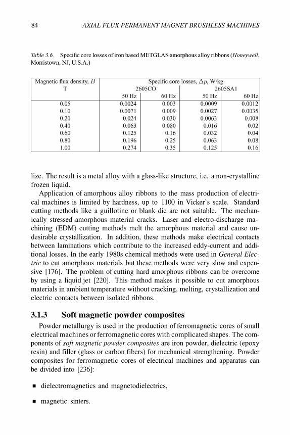
To minimize core losses at high frequencies, nonoriented electrotechnicalsteels should be replaced with amorphous magnetic alloys (Tables 3.5 and3.6). Amorphous ferromagnetic alloys, in comparison with electrical steelswith crystal structure, do not have arranged in order, regular inner crystal struc-ture (lattice).
Amorphous alloy ribbons based on alloys of iron, nickel and cobalt are pro-duced by rapid solidification of molten metals at cooling rates of about
The alloys solidify before the atoms have a chance to segregate or crystal-
83
operating temperature in an inert gas is 850°C, hardness 180 HV and density
3.1.2 Amorphous ferromagnetic alloys
84 AXIAL FLUX PERMANENT MAGNET BRUSHLESS MACHINES
lize. The result is a metal alloy with a glass-like structure, i.e. a non-crystallinefrozen liquid.
Application of amorphous alloy ribbons to the mass production of electri-cal machines is limited by hardness, up to 1100 in Vicker’s scale. Standardcutting methods like a guillotine or blank die are not suitable. The mechan-ically stressed amorphous material cracks. Laser and electro-discharge ma-chining (EDM) cutting methods melt the amorphous material and cause un-desirable crystallization. In addition, these methods make electrical contactsbetween laminations which contribute to the increased eddy-current and addi-tional losses. In the early 1980s chemical methods were used in General Elec-tric to cut amorphous materials but these methods were very slow and expen-sive [176]. The problem of cutting hard amorphous ribbons can be overcomeby using a liquid jet [220]. This method makes it possible to cut amorphousmaterials in ambient temperature without cracking, melting, crystallization andelectric contacts between isolated ribbons.
3.1.3 Soft magnetic powder compositesPowder metallurgy is used in the production of ferromagnetic cores of small
electrical machines or ferromagnetic cores with complicated shapes. The com-ponents of soft magnetic powder composites are iron powder, dielectric (epoxyresin) and filler (glass or carbon fibers) for mechanical strengthening. Powdercomposites for ferromagnetic cores of electrical machines and apparatus canbe divided into [236]:
dielectromagnetics and magnetodielectrics,
magnetic sinters.

Materials and fabrication 85
Dielectromagnetics and magnetodielectrics are names referring to materialsconsisting of the same basic components: ferromagnetic (mostly iron pow-der) and dielectric (mostly epoxy resin) material [236]. The main tasks of thedielectric material is insulation and binding of ferromagnetic particles. In prac-tice, composites containing up to 2% (of their mass) of dielectric materials areconsidered as dielectromagnetics. Those with a higher content of dielectricmaterial are considered as magnetodielectrics [236].
TSC International, Wadsworth, IL, U.S.A., has developed a new soft pow-der material, Accucore, which is competitive to traditional steel laminations[4]. The magnetization curve and specific core loss curves of the non-sinteredAccucore are given in Table 3.7. When sintered, Accucore has higher satura-tion magnetic flux density than the non-sintered material. The specific densityis 7550 to
Höganäs, Höganäs, Sweden, manufactures soft magnetic composite (SMC)powders that are surface-coated metal powders with excellent compressibility

AXIAL FLUX PERMANENT MAGNET BRUSHLESS MACHINES
[216]. 500 (Tables 3.8, 3.9) has been developed for 3D magneticcircuits of electrical machines, transformers, ignition systems and sensors.
86

Materials and fabrication 87
Figure 3.1. Stator core segment formed from lamination strip: 1 — lamination strip, 2 —groove, 3 — folding, 4 — compressed segment, 5 — finished segment.
Normally, the stator cores are wound from electrotechnical steel strips andthe slots are machined by shaping or planing. An alternative method is firstto punch the slots with variable distances between them and then to wind thesteel strip into the form of the slotted toroidal core (R & D Institute of ElectricalMachines VÚES in Brno, Republic of Czech). In addition, this manufacturingprocess allows for making skewed slots to minimize the cogging torque andthe effect of slot harmonics. Each stator core has skewed slots in oppositedirections. It is recommended that a wave stator winding should be made toobtain shorter end connections and more space for the shaft. An odd numberof slots, e.g. 25 instead of 24 can help to reduce the cogging torque (VÚESBrno).
Another technique is to form the stator core using trapezoidal segments[228]. Each segment corresponds to one slot pitch (Fig. 3.1). The lamina-tion strip of constant width is folded at distances proportional to the radius. Tomake folding easy, the strip has transverse grooves on opposite sides of the al-ternative steps. The zigzag laminated segment is finally compressed and fixedusing a tape or thermosetting, as shown in Fig. 3.1 [228].
3.1.4 Fabrication of stator coresFabrication of laminated stator cores
Fabrication of soft magnetic powder stator cores
The laminated cores of axial flux machines are much more difficult to fab-ricate than those of radial flux machines. SMC powders simplify the manufac-turing process of stator cores with complicated shapes, in general, 3D cores.

AXIAL FLUX PERMANENT MAGNET BRUSHLESS MACHINES
Figure 3.2. The effect of compacting pressure on the specific mass density of Höganäs softmagnetic composite powders.
Mass production of AFPM machines is much more cost effective if soft mag-netic powder composites are used as materials for stator cores.
Using SMC powders the stator core of an AFPM machine can be made asa slotted core, slotless cylindrical core and salient pole core with one coil perpole.
The slotted and slotless cylindrical cores for AFPM machines can be madein a powder metallurgy process using a ferromagnetic powder with a smallamount of lubricants or binders. The powder metallurgy process generallyconsists of four basic steps, namely: (1) powder manufacture, (2) mixing orblending, (3) compacting and (4) sintering. Most compacting is done withmechanical, hydraulic or pneumatic presses and rigid tools. Compacting pres-sures generally range between 70 to 800 MPa with 150 to 500 MPa being themost common. The outer diameter of the core is limited by the press capabil-ity. Frequently, the stator core must be divided into smaller segments. Mostpowder metallurgy products must have cross sections of less thanIf the press capacity is sufficient, sections up to can be pressed.Figure 3.2 shows the effect of compacting pressure on the density of HöganäsSMC powders.
For 500 the heat treatment temperature (sintering) is typically500°C for 30 min. After heat treatment the compacted powder has much lessmechanical strength than solid steel.
The thermal expansion of conductors within the stator slots creates thermalexpansion stresses in the stator teeth. The magnitude of these stresses dependsupon the difference in the temperature of the winding and core, difference in
88

Materials and fabrication 89
Figure 3.3. Slotted stators for small single-sided disc-type motors [236].
Figure 3.4. Powder salient pole stators for small single-sided AFPM motors. Courtesy of MiiTechnologies, LLC, West Lebanon, NH, U.S.A.
coefficients of thermal expansion of both materials and slot fill factor. Thisproblem is more important in powder cores than in laminated cores since thetensile stress of powder cores is at least 25 times lower and their modulus ofelasticity is less than 100 GPa (versus 200 GPa for steel laminations).
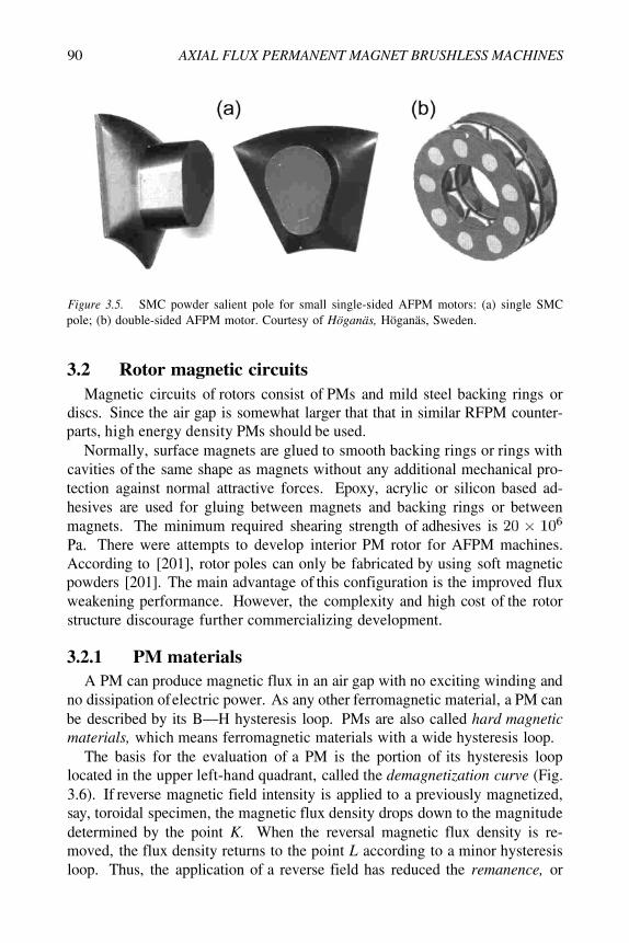
Slotted stators for small disc-type motors fabricated from SMC powdersare shown in Fig. 3.3 [148, 236]. SMC powder salient-pole stators for smallsingle-sided AFPM motors manufactured by Mii Technologies, LLC, Lebanon,NH, U.S.A. are shown in Fig. 3.4. The three-phase stator has 9 poles. A singleSMC powder salient pole manufactured by Höganäs is shown in Fig. 3.5.
90 AXIAL FLUX PERMANENT MAGNET BRUSHLESS MACHINES
Figure 3.5. SMC powder salient pole for small single-sided AFPM motors: (a) single SMCpole; (b) double-sided AFPM motor. Courtesy of Höganäs, Höganäs, Sweden.
3.2 Rotor magnetic circuitsMagnetic circuits of rotors consist of PMs and mild steel backing rings or
discs. Since the air gap is somewhat larger that that in similar RFPM counter-parts, high energy density PMs should be used.
Normally, surface magnets are glued to smooth backing rings or rings withcavities of the same shape as magnets without any additional mechanical pro-tection against normal attractive forces. Epoxy, acrylic or silicon based ad-hesives are used for gluing between magnets and backing rings or betweenmagnets. The minimum required shearing strength of adhesives is
There were attempts to develop interior PM rotor for AFPM machines.According to [201], rotor poles can only be fabricated by using soft magneticpowders [201]. The main advantage of this configuration is the improved fluxweakening performance. However, the complexity and high cost of the rotorstructure discourage further commercializing development.
3.2.1 PM materialsA PM can produce magnetic flux in an air gap with no exciting winding and
no dissipation of electric power. As any other ferromagnetic material, a PM canbe described by its B—H hysteresis loop. PMs are also called hard magneticmaterials, which means ferromagnetic materials with a wide hysteresis loop.
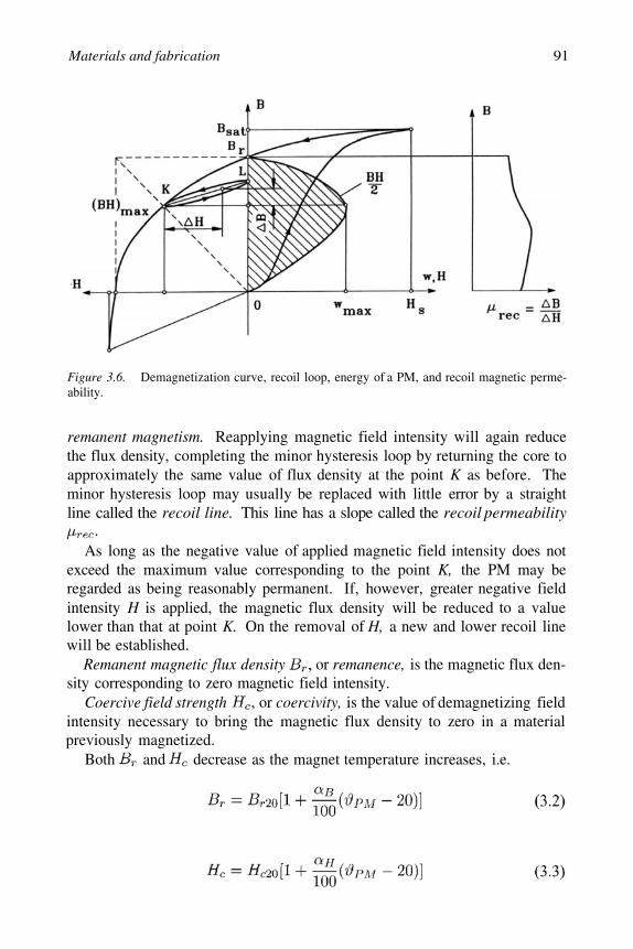
The basis for the evaluation of a PM is the portion of its hysteresis looplocated in the upper left-hand quadrant, called the demagnetization curve (Fig.3.6). If reverse magnetic field intensity is applied to a previously magnetized,say, toroidal specimen, the magnetic flux density drops down to the magnitudedetermined by the point K. When the reversal magnetic flux density is re-moved, the flux density returns to the point L according to a minor hysteresisloop. Thus, the application of a reverse field has reduced the remanence, or
Materials and fabrication 91
Figure 3.6. Demagnetization curve, recoil loop, energy of a PM, and recoil magnetic perme-ability.
remanent magnetism. Reapplying magnetic field intensity will again reducethe flux density, completing the minor hysteresis loop by returning the core toapproximately the same value of flux density at the point K as before. Theminor hysteresis loop may usually be replaced with little error by a straightline called the recoil line. This line has a slope called the recoil permeability
As long as the negative value of applied magnetic field intensity does notexceed the maximum value corresponding to the point K, the PM may beregarded as being reasonably permanent. If, however, greater negative fieldintensity H is applied, the magnetic flux density will be reduced to a valuelower than that at point K. On the removal of H, a new and lower recoil linewill be established.
Remanent magnetic flux density or remanence, is the magnetic flux den-sity corresponding to zero magnetic field intensity.
Coercive field strength or coercivity, is the value of demagnetizing fieldintensity necessary to bring the magnetic flux density to zero in a materialpreviously magnetized.
Both and decrease as the magnet temperature increases, i.e.

92 AXIAL FLUX PERMANENT MAGNET BRUSHLESS MACHINES
Figure 3.7. Comparison of B—H and demagnetization curves and their variationswith the temperature for sintered N48M NdFeB PMs. Courtesy of ShinEtsu, Takefu-shi, FukuiPrefecture, Japan.
where is the temperature of PM, and are the remanent mag-netic flux density and coercive force at 20°C and and aretemperature coefficients for and in %/°C respectively. Thus, demagne-tization curves are sensitive to the temperature (Fig. 3.7).
Intrinsic demagnetization curve (Fig. 3.7) is the portion of thehysteresis loop located in the upper left-hand quadrant, whereFor H = 0 the intrinsic magnetic flux density
Intrinsic coercivity is the magnetic field strength required to bring tozero the intrinsic magnetic flux density of a magnetic material described bythe curve. For PM materials
Saturation magnetic flux density corresponds to high values of the mag-netic field intensity, when an increase in the applied magnetic field produces nofurther effect on the magnetic flux density. In the saturation region the align-ment of all the magnetic moments of domains is in the direction of the externalapplied magnetic field.
Recoil magnetic permeability is the ratio of the magnetic flux density–to–magnetic field intensity at any point on the demagnetization curve, i.e.

Materials and fabrication 93
where the relative recoil permeabilityMaximum magnetic energy per unit produced by a PM in the external space
is equal to the maximum magnetic energy density per volume, i.e.
where the product corresponds to the maximum energy densitypoint on the demagnetization curve with coordinates and (Fig.3.6).
Form factor of the demagnetization curve characterizes the concave shapeof the demagnetization curve, i.e.
for a square demagnetization curve and for a straight line (rare-earthPMs)
The leakage flux causes the magnetic flux to be distributed nonuniformlyalong the height of a PM, where is the height per pole. As a result,the MMF produced by the PM is not constant. The magnetic flux is higher inthe neutral cross section and lower at the ends, but the behavior of the MMFdistribution is the opposite [96].
The PM surface is not equipotential. The magnetic potential at each pointon the surface is a function of the distance to the neutral zone. To simplifythe calculation, the magnetic flux which is a function of the MMF distributionalong the height per pole is replaced by an equivalent flux. This equivalentflux goes through the whole height and exits from the surface of the poles.To find the equivalent leakage flux and the whole flux of a PM, the equivalentmagnetic field intensity needs to be found, i.e.
where is the magnetic field intensity at a distance from the neutral crosssection and is the MMF of the PM per pole per pole pair).
The equivalent magnetic field intensity (3.7) allows the equivalent leakageflux of the PM to be found, i.e.
where is the full equivalent flux of the PM and is the air gap magneticflux. The coefficient of leakage flux of the PM,

94 AXIAL FLUX PERMANENT MAGNET BRUSHLESS MACHINES
simply allows the air gap magnetic flux to be expressed asThe following leakage permeance expressed in the flux coordinate
system corresponds to the equivalent leakage flux of the PM:
An accurate estimation of the leakage permeance is the most difficulttask in analytical calculation of magnetic circuits with PMs. Using the fieldapproach, e.g. the FEM, the leakage permeance can be found fairly accurately.
The average equivalent magnetic flux and equivalent MMF mean that themagnetic flux density and magnetic field intensity are assumed to be the samein the whole volume of a PM. The full energy produced by the magnet in theouter space is
where is the volume of the PM or a system of PMs.For a PM circuit with a rectangular cross section, single PM and two mild
steel pole shoes, the magnetic flux density in a given air gap volumeis directly proportional to the square root of the magnetic energy prod-
uct [96], i.e.
where is the magnetic field intensity in the mild steel yoke, is themagnetic field intensity in the air gap, is the magnet vol-ume, is the PM width, is the PM length and is the length of themagnetic flux path in two mild steel pole shoes. Following the trend to smallerpackaging, smaller mass and higher efficiency, the material research in the fieldof PMs has focused on finding materials with high values of the maximum en-ergy product
The air gap magnetic flux density can be estimated analytically on thebasis of the demagnetization curve, air gap and leakage permeance lines and

Materials and fabrication 95
recoil lines [96]. Approximately, it can be found on the basis of the balance ofthe magnetic voltage drops, i.e.
where is the relative permeability of the PM (relative recoil permeability).Hence,
The air gap magnetic flux density is proportional to the remanent magneticflux density and decreases as the air gap increases. Eqn (3.13) can onlybe used for preliminary calculations.
For rare-earth PMs the approximation of the demagnetization curve is sim-ple due to practically linear demagnetization curve, i.e.
The approximation of more complicated demagnetizations curves (Alnico orferrites) is given e.g. in [96].
The intersection point of the above demagnetization curve (3.14) and thefollowing line representing the permeance of the air gap
gives a point called the operating point. This point corresponds to the air gapmagnetic flux density multiplied by the leakage coefficient accordingto eqn (3.9).
3.2.2 Characteristics of PM materialsThere are three classes of PMs currently used for electric motors:
Alnicos (Al, Ni, Co, Fe);
Ceramics (ferrites), e.g. barium ferrite and strontium ferrite
Rare-earth materials, i.e. samarium-cobalt SmCo and neodymium-iron-boron NdFeB.
The demagnetization curves of the above three types of permanent magnetmaterials are given in Fig. 3.8.

96 AXIAL FLUX PERMANENT MAGNET BRUSHLESS MACHINES
Figure 3.8. Demagnetization curves for different PM materials.
AlnicoAlnico magnets dominated the PM motor market in the range from a few
watts to 150 kW between the mid 1940s and the late 1960s. The main advan-tages of Alnico are its high magnetic remanent flux density and low tempera-ture coefficients (Table 3.10). The temperature coefficient of is –0.02%/°Cand maximum service temperature is 520°C. Unfortunately, the coercive forceis very low and the demagnetization curve is extremely non-linear. Therefore,it is very easy not only to magnetize but also to demagnetize Alnico. Alnicohas been used in PM d.c. commutator motors of the disc type with relativelylarge air gaps. This results in a negligible armature reaction magnetic fluxacting on the PMs. Sometimes, Alnico PMs are protected from the armatureflux, and consequently from demagnetization, using additional mild steel poleshoes.
FerritesBarium and strontium ferrites produced by powder metallurgy were in-
vented in the 1950s. Their chemical formulation may be expressed aswhere M is Ba, Sr, or Pb. Ferrite magnets are available in isotropic
and anisotropic grades.A ferrite has a higher coercive force than Alnico, but at the same time has
a lower remanent magnetic flux density (Table 3.10). Temperature coefficientsare relatively high, i.e. the coefficient of is – 0.20%/°C and the coefficientof is –0.27 to –0.4%/°C. The maximum service temperature is 450°C.The main advantages of ferrites are their low cost and very high electric re-

Materials and fabrication 97
sistance, which means practically no eddy-current losses in the PM volume.Ferrite magnets are most economical in fractional horsepower motors. Bariumferrite PMs are commonly used in small d.c. commutator motors for automo-biles (blowers, fans, windscreen wipers, pumps, etc.) and electric toys.
Rare-earth permanent magnets
The first generation of rare-earth permanent magnets, i.e. alloys based onthe composition of has been commercially produced since the early1970s (invented in the 1960s). has the advantage of a high remanentflux density, high coercive force, high energy product, a linear demagnetiza-tion curve and a low temperature coefficient (Table 3.11). The temperaturecoefficient of is – 0.02 to – 0.045%/°C and the temperature coefficient of
is – 0.14 to – 0.40%/°C. Maximum service temperature is 300 to 350°C.It is suitable for motors with low volumes and motors operating at increasedtemperatures, e.g. brushless generators for microturbines. Both Sm and Co arerelatively expensive due to their supply restrictions.

98 AXIAL FLUX PERMANENT MAGNET BRUSHLESS MACHINES
With the discovery in the recent years of a second generation of rare-earthmagnets on the basis of inexpensive neodymium (Nd), remarkable progresswith regard to lowering raw material costs has been achieved. The new gener-ation of rare-earth PMs based on inexpensive neodymium (Nd) was announcedby Sumitomo Special Metals, Japan, in 1983 at the 29th Annual Conference ofMagnetism and Magnetic Materials held in Pittsburgh, PA, U.S.A. The Nd is amuch more abundant rare-earth element than Sm. NdFeB magnets, which arenow produced in increasing quantities have better magnetic properties (Table3.12) than those of SmCo, but unfortunately only at room temperature. The de-magnetization curves, especially the coercive force, are strongly temperaturedependent. The temperature coefficient of is – 0.09 to – 0.15%/°C and thetemperature coefficient of is – 0.40 to – 0.80%/°C. The maximum service

Materials and fabrication 99
temperature is 250°C and Curie temperature is 350°C. The NdFeB is also sus-ceptible to corrosion. NdFeB magnets have great potential for considerablyimproving the performance–to–cost ratio for many applications. For this rea-son they will have a major impact on the development and application of PMmachines in the future.
Chemical reactivity of rare-earth magnets is similar to that of alkaline earthmetals, e.g. magnesium. The reaction is accelerated at increased tempera-ture and humidity. The NdFeB alloy if exposed to hydrogen gas, usually ata slightly elevated temperature and/or elevated pressure, becomes brittle andwith very little effort, it can be crushed. Diffusion of hydrogen into the alloycauses it literally to fall apart.
Corrosion protective coatings can be divided into metallic and organic. Formetallic coatings, e.g. nickel and tin, galvanic processes are used as a rule.Organic coatings include powder coatings applied electrostatically, varnishesand resins.
Nowadays, for the industrial production of rare-earth PMs the powder met-allurgical route is mainly used [194]. Apart from some material specific pa-rameters, this processing technology is, in general, the same for all rare-earthmagnet materials. The alloys are produced by vacuum induction melting orby a calciothermic reduction of the oxides. The material is then size-reducedby crushing and milling to a single crystalline powder with particle sizes lessthan In order to obtain anisotropic PMs with the highest possible
value, the powders are then aligned in an external magnetic field,pressed and densified to nearly theoretical density by sintering. The most eco-nomical method for mass production of simply shaped parts like blocks, ringsor arc segments is die pressing of the powders in approximately the final shape.
Researchers at General Motors, U.S.A., developed a fabrication methodbased on the melt-spinning casting system originally invented for the produc-tion of amorphous metal alloys. In this technology a molten stream of NdFe-CoB material is first formed into ribbons 30 to thick by rapid quench-ing, then cold pressed, extruded and hot pressed into bulk. Hot pressing andhot working are carried out while maintaining the fine grain to provide a highdensity close to 100% which eliminates the possibility of internal corrosion.The standard electro-deposited epoxy resin coating provides excellent corro-sion resistance.
The prices of NdFeB magnets ordered in large quantities are now belowUS$20 per kg. Owing to a large supply of NdFeB magnets from China it isexpected that the prices will fall further.
3.2.3 Operating diagramThe energy of a PM in the external space only exists if the reluctance of the
external magnetic circuit is higher than zero. If a previously magnetized PM

100 AXIAL FLUX PERMANENT MAGNET BRUSH LESS MACHINES
is placed inside a closed ideal ferromagnetic circuit, i.e. toroid, this PM doesnot show any magnetic properties in the external space, in spite of the fact thatthere is the magnetic flux
corresponding to the remanent flux density inside the PM.A PM previously magnetized and placed alone in an open space, as in Fig.
3.9a, generates a magnetic field. To sustain a magnetic flux in the externalopen space, an MMF developed by the magnet is necessary. The state of thePM is characterized by the point K on the demagnetization curve (Fig. 3.10).The location of the point K is at the intersection of the demagnetization curvewith a straight line representing the permeance of the external magnetic circuit(open space):

Materials and fabrication 101
Figure 3.9. Stabilization of a PM: (a) PM alone, (b) PM with pole shoes, (c) PM inside anexternal magnetic circuit, (d) PM with a complete external armature system.
The permeance corresponds to the flux coordinate system andis referred to as MMF at the ends of the PM. In the coordinatesystem the remanent flux is according to eqn (3.16) and the MMF corre-sponding to the coercivity is
The magnetic energy per unit produced by the PM in the external space isThis energy is proportional to the rectangle limited by the
coordinate system and lines perpendicular to the and coordinates pro-jected from the point K. It is obvious that the maximum magnetic energy isfor and for
If the poles are furnished with pole shoes (Fig. 3.9b) the permeance of theexternal space increases. The point which characterizes a new state of the PMin Fig. 3.10 moves along the recoil line from the point K to the point A. Therecoil line is the same as the internal permeance of the PM, i.e.
The point A is the intersection of the recoil line and the straight linerepresenting the leakage permeance of the PM with pole shoes, i.e.

102 AXIAL FLUX PERMANENT MAGNET BRUSHLESS MACHINES
The energy produced by the PM in the external space decreases as comparedwith the previous case, i.e.
The next stage is to place the PM in an external ferromagnetic circuit asshown in Fig. 3.9c. The resultant permeance of this system is
which meets the condition For an external magnetic circuitwithout any electric circuit carrying the armature current, the magnetic state ofthe PM is characterized by the point P (Fig. 3.10), i.e. the intersection of therecoil line and the permeance line
When the external magnetic circuit is furnished with an armature windingand when this winding is fed with a current which produces an MMF magne-tizing the PM (Fig. 3.9d), the magnetic flux in the PM increases to the value
The MMF of the external (armature) field acting directly onthe PM corresponds to The magnetic state of the PM is described by thepoint N located on the recoil line on the right-hand side of the origin of thecoordinate system. To obtain this point it is necessary to lay off the distance
and to draw a line from the point inclined by the angle to theF-axis. The intersection of the recoil line and the permeance line Gp gives thepoint N. If the exciting current in the external armature winding is increasedfurther, the point N will move further along the recoil line to the right, up tothe saturation of the PM.
Figure 3.10. Diagram of a PM for finding the origin of the recoil line and operating point.

Materials and fabrication 103
When the excitation current is reversed, the external armature magnetic fieldwill demagnetize the PM. In this case it is necessary to lay off the distance
from the origin of the coordinate system to the left (Fig. 3.10). The linedrawn from the point with the slope intersects the demagnetization
curve at the point This point can be above or below the point K (for thePM alone in the open space). The point is the origin of a new recoil line
Now if the armature exciting current decreases, the operating pointwill move along the new recoil line to the right. If the armature currentdrops down to zero, the operating point takes the position (intersection ofthe new recoil line with the permeance line drawn from the originof the coordinate system).
On the basis of Fig. 3.10 the energiesand The location of the origin of the recoil line, as well as thelocation of the operating point, determine the level of utilization of the energyproduced by the PM. A PM behaves differently than a d.c. electromagnet: theenergy of a PM is not constant if the permeance and exciting current of theexternal armature changes.
The location of the origin of the recoil line is determined by the minimumvalue of the permeance of the external magnetic circuit or the demagnetizationaction of the external field.
To obtain the properties of PMs more independent of the external magneticfields, PMs need to be stabilized. Stabilization means the PM is demagnetizedup to a value which is slightly higher than the most dangerous demagnetizationfield during the operation of a system where the PM is installed. In magneticcircuits with stabilized PMs the operating point describing the state of the PMis located on the recoil line.
More details about how to find the operating point of a PM graphically andanalytically can be found in [96].
3.2.4 Permeances for main and leakage fluxesPermeances of air gaps and permeances for leakage fluxes can be found
analytically by dividing the magnetic field into simple solids. Permeances ofsimple solids shown in Fig. 3.11 can be found using the following formulae:
(a) Rectangular prism (Fig. 3.11a)

104 AXIAL FLUX PERMANENT MAGNET BRUSHLESS MACHINES
Figure 3.11. Simple solids: (a) rectangular prism, (b) cylinder, (c) half-cylinder, (d) one-quarter of a cylinder, (e) half-ring, (f) one-quarter of a ring, (g) one-quarter of a sphere, (h)one-eighth of a sphere, (i) one-quarter of a shell, (j) one-eighth of a shell.

Materials and fabrication 105
(b) Cylinder (Fig. 3.11b)
(c) Half-cylinder (Fig. 3.11c)
where the average air gap and the surface should bereplaced by [13]
(d) One-quarter of a cylinder (Fig. 3.11d)
(e) Half-ring (Fig. 3.11e)
For
(f) One-quarter of a ring (Fig. 3.11f)
For
(g) One-quarter of a sphere (Fig. 3.11g)
106 AXIAL FLUX PERMANENT MAGNET BRUSHLESS MACHINES
(h) One-eighth of a sphere (Fig. 3.11h)
(i) One-quarter of a shell (Fig. 3.11i)
(j) One-eighth of a shell (Fig. 3.11j)
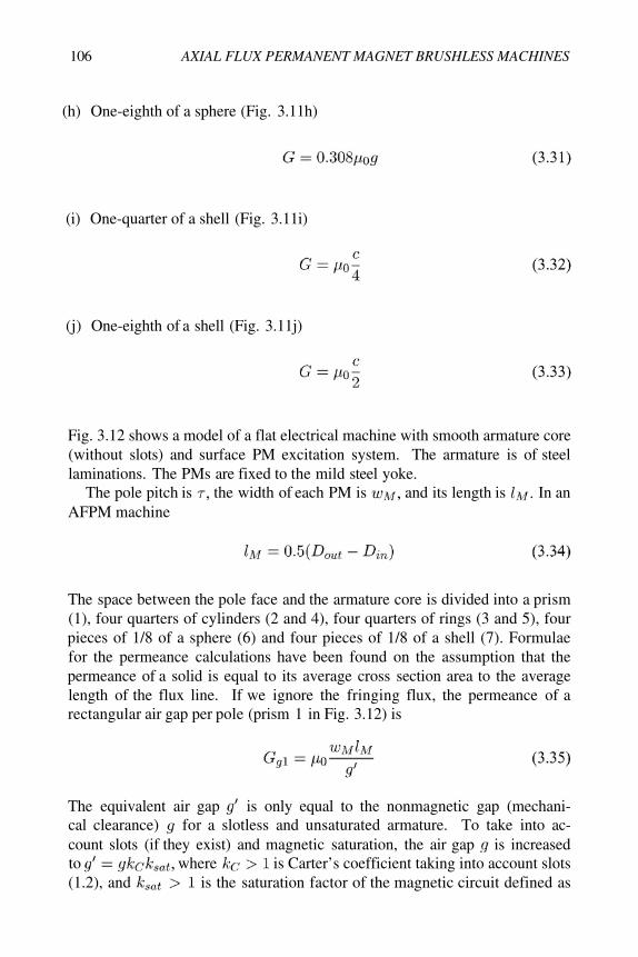
Fig. 3.12 shows a model of a flat electrical machine with smooth armature core(without slots) and surface PM excitation system. The armature is of steellaminations. The PMs are fixed to the mild steel yoke.
The pole pitch is the width of each PM is and its length is In anAFPM machine
The space between the pole face and the armature core is divided into a prism(1), four quarters of cylinders (2 and 4), four quarters of rings (3 and 5), fourpieces of 1/8 of a sphere (6) and four pieces of 1/8 of a shell (7). Formulaefor the permeance calculations have been found on the assumption that thepermeance of a solid is equal to its average cross section area to the averagelength of the flux line. If we ignore the fringing flux, the permeance of arectangular air gap per pole (prism 1 in Fig. 3.12) is
The equivalent air gap is only equal to the nonmagnetic gap (mechani-cal clearance) for a slotless and unsaturated armature. To take into ac-count slots (if they exist) and magnetic saturation, the air gap is increasedto where is Carter’s coefficient taking into account slots(1.2), and is the saturation factor of the magnetic circuit defined as

Materials and fabrication 107
Figure 3.12. Electrical machine with flat slotless armature and flat PM excitation system —division of the space occupied by the magnetic field into simple solids: (a) longitudinal section,(b) air gap field, (c) leakage field (between the PM and steel yoke).
the ratio of the MMF per pole pair to the air gap magnetic voltage drop (MVD)taken twice [96].
To take into account the fringing flux it is necessary to include all paths forthe magnetic flux coming from the excitation system through the air gap to thearmature system (Fig. 3.12), i.e.
where is the air gap permeance according to eqn (3.35) and toare the air gap permeances for fringing fluxes. The permeances to canbe found using eqns (3.25), (3.28), (3.31) and (3.32).
In a similar way the resultant permeance for the leakage flux of the PM canbe found, i.e.
where (one-quarter of a cylinder) and (one-eight of a sphere) arethe permeances for leakage fluxes between the PM and rotor yoke accordingto Fig. 3.12c — eqns (3.25) and (3.31).
3.2.5 Calculation of magnetic circuits with PMsThe equivalent magnetic circuit of a PM system with armature is shown in
Fig. 3.13. The reluctances of pole shoes (mild steel) and armature stack (elec-trotechnical laminated steel) are much smaller than those of the air gap and

108 AXIAL FLUX PERMANENT MAGNET BRUSHLESS MACHINES
Figure 3.13. Equivalent circuit (in the of a PM system with armature.
PM and have been neglected. The “open circuit” MMF acting along the inter-nal magnet permeance is the armaturereaction MMF is the total magnetic flux of the PM is the leakage fluxof the PM is the useful air gap magnetic flux is the leakage flux of theexternal armature system is the flux in the produced by the arma-ture is (demagnetizing or magnetizing), the reluctance for the PM leakageflux is the air gap reluctance is and the exter-nal armature leakage reluctance is The following Kirchhoff’sequations can be written on the basis of the equivalent circuit shown in Fig.3.13
The solution to the above equation system yields the air gap magnetic flux:
or

Materials and fabrication 109
Figure 3.14. Shapes of PM rotors of disc-type machines: (a) trapezoidal, (b) circular, (c)semicircular.
where the total resultant permeance for the flux of the PM is
and the direct-axis armature MMF acting directly on the PM is
The upper sign in eqn (3.38) is for the demagnetizing armature flux and thelower sign is for the magnetizing armature flux.
The coefficient of the PM leakage flux (3.9) can also be expressed in termsof permeances, i.e.
3.2.6 Fabrication of rotor magnetic circuitsMagnetic circuits of rotors of AFPM brushless machines provide the exci-
tation flux and are designed as:
PMs glued to a ferromagnetic ring or disc which serves as a backing mag-netic circuit (yoke);
PMs arranged into Halbach array without any ferromagnetic core.
Shapes of PMs are usually trapezoidal, circular or semicircular (Fig. 3.14).The shape of PMs affects the distribution of the air gap magnetic field andcontents of higher space harmonics. The output voltage quality (harmonics of

110 AXIAL FLUX PERMANENT MAGNET BRUSHLESS MACHINES
the EMF) of AFPM generators depends on the PM geometry (circular, semi-circular, trapezoidal) and distance between adjacent magnets [75].
Since the magnetic flux in the rotor magnetic circuit is stationary, mild steel(carbon steel) backing rings can be used. Rings can be cut from 4 to 6 mmmild steel sheets. Table 3.13 shows magnetization characteristics B–H of amild carbon steel and cast iron. Electrical conductivities of carbon steels arefrom to at 20°C.
Halbach array
Twin rotors of double-sided coreless AFPM machines (Fig. 1.4d) may usePMs arranged in Halbach array [104–106]. The key concept of Halbach arrayis that the magnetization vector of PMs should rotate as a function of distance
Figure 3.15. Cartesian Halbach array.

Materials and fabrication 111
along the array (Fig. 3.15) [104–106]. Halbach array has the following advan-tages:
the fundamental field is stronger by a factor of 1.4 than in a conventionalPM array, and thus the power efficiency of the machine is doubled;
the array of PMs does not require any backing steel magnetic circuit andPMs can be bonded directly to a non-ferromagnetic supporting structure(aluminum, plastics);
the magnetic field is more sinusoidal than that of a conventional PM array;
Halbach array has very low back-side fields.
The peak value of the magnetic flux density at the active surface of Halbacharray is
where is the remanent magnetic flux density of the magnet,see also eqn (1.6), is the spatial period (wavelength) of the array andis the number of PM pieces per wavelength. For the array shown in Fig. 3.15
For example, assuming(rectangular PMs), the peak magnetic flux density at the surface of
Halbach arrayThe tangential and normal components of Halbach array at the dis-
tance from the surface of PMs are
For a double-sided configuration of Halbach arrays, i.e. twin disc externalrotors, the tangential and normal component of the magnetic flux density dis-tribution in the space between discs are

112 AXIAL FLUX PERMANENT MAGNET BRUSHLESS MACHINES
where is according to eqn (3.42) and is magnet–to–magnet distancebetween two halves of the disc. The origin of the 0xyz coordinate system is asin Fig. 1.8.
3.3 Windings3.3.1 Conductors
Stator (armature) windings of electric motors are made of solid copper con-ductor wires with round or rectangular cross sections.
The electric conductivity at 20°C of copper wires isFor aluminum wires The electric conductivity
is temperature dependent and for can be expressed as
where is the temperature coefficient of electric resistance. For copper wiresand for aluminum wires For
eqn (3.47) contains two temperature coefficients and of the electricresistance, i.e.
The maximum temperature rise for the windings of electrical machines is de-termined by the temperature limits of insulating materials. The maximum tem-perature rise in Table 3.14 assumes that the temperature of the cooling medium
The maximum temperature of windings is actually
where is the maximum allowable temperature rise according to Table 3.14.A polyester-imide and polyamide-imide coat can provide an operating tem-perature of 200°C. The highest operating temperatures (over 600°C) can beachieved using nickel clad copper or palladium-silver conductor wires and ce-ramic insulation.
3.3.2 Fabrication of slotted windingsStator windings are usually made of insulated copper conductors. The cross
section of conductors can be circular or rectangular. For large AFPM machinesa direct water cooling system and consequently hollow conductors can be con-sidered.
It is difficult to make and form stator coils if the round conductor is thickerthan 1.5 mm. If the current density is too high, parallel conductor wires of

Materials and fabrication 113
smaller diameter are recommended rather than one thicker wire. Stator wind-ings can also have parallel current paths.
The armature windings can be either single-layer or double layer (Section2.2). After coils are wound, they must be secured in place, somehow, so asto avoid conductor movement. Two standard methods are used to secure theconductors of electrical machines in place:
dipping the whole component into a varnish-like material, and then bakingoff its solvent,
trickle impregnation method, which uses heat to cure a catalyzed resinwhich is dripped onto the component.
Polyester, epoxy or silicon resins are used most often as impregnating materialsfor treatment of stator windings. Silicon resins of high thermal endurance areable to withstand
Recently, a new method of conductor securing that does not require any ad-ditional material, and uses very low energy input, has emerged [163]. The solidconductor wire (usually copper) is coated with a heat and/or solvent activatedadhesive. The adhesive which is usually a polyvinyl butyral, utilizes a low tem-perature thermoplastic resin [163]. This means that the bonded adhesive cancome apart after a certain minimum temperature is reached, or it again comesin contact with the solvent. Normally this temperature is much lower than the

114 AXIAL FLUX PERMANENT MAGNET BRUSHLESS MACHINES
Figure 3.16. Disc-type coreless winding assembled of coils of the same shape according toU.S. Patent No. 5 744 896 [139]: (a) single coil; (b) three adjacent coils. 1 — coil side, 2 —inner offsetting bend, 3 — outer offsetting bend.
thermal rating of the base insulation layer. The adhesive is activated by eitherpassing the wire through a solvent while winding or heating the finished coilas a result of passing electric current through it.
The conductor wire with a heat activated adhesive overcoat costs more thanthe same class of non-bondable conductor. However, a less than two secondcurrent pulse is required to bond the heat activated adhesive layer and bondingmachinery costs about half as much as trickle impregnation machinery [163].
3.3.3 Fabrication of coreless windingsStator coreless windings of AFPM machines are fabricated as uniformly
distributed coils on a disc-type cylindrical supporting structure (hub) made ofnonmagnetic and nonconductive material. There are two types of windings:
(a)
(b)
winding comprised of multi-turn coils wound with turns of insulated con-ductor of round or rectangular cross section;
printed winding also called film coil winding.
Coils are connected in groups to form the phase windings typically connectedin star or delta. Coils or groups of coils of the same phase can be connected inparallel to form parallel paths.
To assemble the winding of the same coils and obtain high density packing,coils should be formed with offsetting bends, as shown in Fig. 3.16. The spacebetween two sides of the same coil is filled with coil sides from each of theadjacent coils.
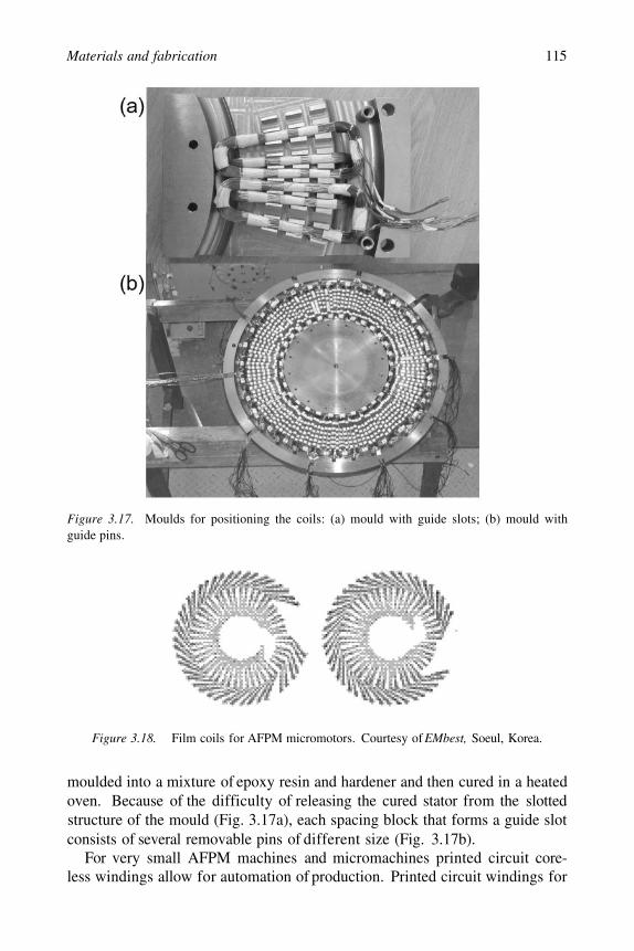
Coils can be placed in a slotted structure of the mould (Fig. 3.17). With allthe coils in position, the winding (often with a supporting structure or hub) is
Materials and fabrication 115
Figure 3.17. Moulds for positioning the coils: (a) mould with guide slots; (b) mould withguide pins.
Figure 3.18. Film coils for AFPM micromotors. Courtesy of EMbest, Soeul, Korea.
moulded into a mixture of epoxy resin and hardener and then cured in a heatedoven. Because of the difficulty of releasing the cured stator from the slottedstructure of the mould (Fig. 3.17a), each spacing block that forms a guide slotconsists of several removable pins of different size (Fig. 3.17b).
For very small AFPM machines and micromachines printed circuit core-less windings allow for automation of production. Printed circuit windings for

116 AXIAL FLUX PERMANENT MAGNET BRUSHLESS MACHINES
AFPM brushless machines fabricated in a similar way as printed circuit boardshave not been commercialized due to poor performance. A better performancehas been achieved using film coil windings made through the same process asflexible printed circuits [85]. The coil pattern is formed by etching two copperfilms that are then attached to both sides of a board made of insulating mate-rials (Fig. 3.18). Compact coil patterns are made possible by connecting bothsides of coil patterns through holes [85].
Numerical example 3.1A simple stationary magnetic circuit is shown in Fig. 3.19. There are two
Vacomax 240 HR SmCo PMs (Table 3.11) withtemperature coefficients and at
The height of the PM per pole is and the air gapthickness The U-shaped and I-shaped (top) ferromagnetic coresare made of a laminated electrotechnical steel. The width of the magnets andcores is 17 mm. Calculate the air gap magnetic flux density, air gap magneticfield strength, the useful energy of PMs and normal attractive force per twopoles at: (a) and (b) The MVD in the laminatedcore, leakage and fringing magnetic flux can be neglected.
Solution:
(a) Magnet temperature
The relative recoil magnetic permeability according to eqn (3.4) for a straightlinc demagnetization curve is
The air gap magnetic flux density according to eqn (3.13) is
The air gap magnetic field strength according to eqn (3.14) in whichand is
The useful energy per magnet volume according to eqn (3.5) is

Materials and fabrication 117
Figure 3.19. A simple stationary magnetic circuit with PMs and air gap. Numerical example3.1.
The useful energy per pole pair is
The normal attractive force per 2 poles is
(b) Magnet temperature
The remanent magnetic flux density and coercivity at 100°C according to eqns(3.2) and (3.3) is
At the demagnetization curve is nonlinear. Its linear part is onlybetween 0.5 T and parallel to the demagnetization curve at 20°C. Thus, therelative recoil magnetic permeability and air gap magnetic field strength
at 100°C are approximately the same as those at room temperature.The air gap magnetic flux density according to (3.13) is

118 AXIAL FLUX PERMANENT MAGNET BRUSHLESS MACHINES
The useful energy per magnet volume is
The useful energy per pole pair is
The normal attractive force per 2 poles is
Numerical example 3.2A single-sided, 8-pole AFPM machine with slotted ferromagnetic stator has
the PM outer diameter and inner diameterThe air gap including the effect of slotting (Carter coefficient) is
Trapezoidal sintered NdFeB magnets have and at 20°C. The temperature coefficient for is and
the temperature coefficient for is The coefficient ofPM leakage flux is and pole width-to-pole pitch coefficient is
Find PM dimensions to obtain the air gap magnetic flux density at no-load and temperature Sketch operating diagrams in the
B–H and coordinate system at no load. Assume that the magneticcircuit is unsaturated.
Solution:
The remanence and coercivity at according to eqns (3.2) and(3.3) is
Approximation of demagnetization curves according to eqn (3.14) at 20°C and80°C respectively

Materials and fabrication 119
The relative recoil magnetic permeability according to eqn (3.4) is
The axial height of the PM per pole according to eqn (3.13) is
The equivalent air gap is
The average diameter, pole pitch (1.9), length (3.34) and width of the magnetare respectively
The permeance of the air gap according to eqn (2.23) is
or
The total permeance for magnetic flux including leakage permeances is
Approximation of the total permeance (air gap and leakage) line can be ex-pressed as a linear function of H
The magnetic field intensity corresponding to the operating point of the magnetis calculated as
120 AXIAL FLUX PERMANENT MAGNET BRUSHLESS MACHINES
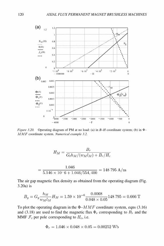
Figure 3.20. Operating diagram of PM at no load: (a) in B–H coordinate system; (b) incoordinate system. Numerical example 3.2.
The air gap magnetic flux density as obtained from the operating diagram (Fig.3.20a) is
To plot the operating diagram in the coordinate system, eqns (3.16)and (3.18) are used to find the magnetic flux corresponding to and theMMF per pole corresponding to i.e.

Materials and fabrication 121
Approximation of the magnetic flux line is
The MMF corresponding to the operating point of the magnet in thecoordinate system (Fig. 3.20b) is
The air gap flux line (Fig. 3.20b) is
The total flux line (Fig. 3.20b) is
The air gap magnetic flux corresponding to the operating point isThe air gap magnetic flux density is
Numerical example 3.3The magnetic field in the air gap of an AFPM machine with coreless stator
is excited by sintered NdFeB magnets arranged in Halbach array. The externaltwin rotors do not have any backing steel discs (Fig. 1.4d). The remanentmagnetic flux density is the height of the PM isthe wavelength at the average diameter is and the magnet-to-magnet distance is
Find the distribution of the magnetic flux density in the space between mag-nets for the 90-degree Halbach array, i.e. Estimate, how the number
of PMs per wavelength affects the magnetic flux density at the active sur-face of PMs.
Solution
The peak value of the magnetic flux density at the active surface of Halbacharray according to eqn (3.42) is
122 AXIAL FLUX PERMANENT MAGNET BRUSHLESS MACHINES
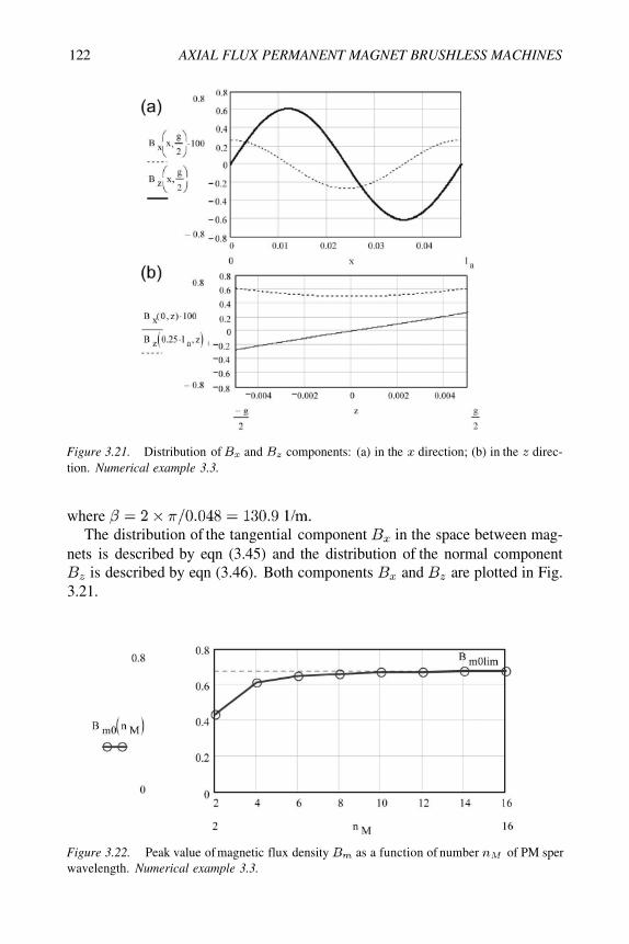
Figure 3.21. Distribution of and components: (a) in the direction; (b) in the direc-tion. Numerical example 3.3.
whereThe distribution of the tangential component in the space between mag-
nets is described by eqn (3.45) and the distribution of the normal componentis described by eqn (3.46). Both components and are plotted in Fig.
3.21.
Figure 3.22. Peak value of magnetic flux density as a function of number of PM sperwavelength. Numerical example 3.3.

Materials and fabrication 123
For the 90-degree Halbach array the peak value of the magneticflux density at the active surface of PMs is Similarly, using eqn(3.42), the peak value can be calculated for other Halbach configurations.For 60-degree Halbach array and for 45-degreeHalbach array In general,
since The peak value as a function of numberof PMs per wavelength is shown in Fig. 3.22.