MasterLogic-200R - Maxima Automation Room Instrumentation... · R200 Programmable Logic Controller...
235
Honeywell Process Solutions Programmable Logic Controller MasterLogic-200R User's Guide 2MLR-CPUH/T, F 2MLR-DBST, F, H 2MLR-M06P 2MLR-E12P 2MLR-AC12,13,22,23 2MLR-DC42 R200 April 2010 Release 200 Honeywell
Transcript of MasterLogic-200R - Maxima Automation Room Instrumentation... · R200 Programmable Logic Controller...

Honeywell Process Solutions
Programmable Logic Controller
MasterLogic-200R User's Guide
2MLR-CPUH/T, F
2MLR-DBST, F, H
2MLR-M06P
2MLR-E12P
2MLR-AC12,13,22,23
2MLR-DC42
R200
April 2010
Release 200
Honeywell

ii Programmable Logic Controller MasterLogic-200R User's Guide R200 Honeywell April 2010
Notices and Trademarks
Copyright 2010 by Honeywell International Sárl. Release 200 April, 2010
While this information is presented in good faith and believed to be accurate, Honeywell disclaims the implied warranties of merchantability and fitness for a particular purpose and makes no express warranties except as may be stated in its written agreement with and for its customers.
In no event is Honeywell liable to anyone for any indirect, special or consequential damages. The information and specifications in this document are subject to change without notice.
Honeywell, PlantScape, Experion PKS, and TotalPlant are registered trademarks of Honeywell International Inc.
Other brand or product names are trademarks of their respective owners.
Honeywell Process Solutions
1860 W. Rose Garden Lane
Phoenix, AZ 85027 USA
1-800 822-7673

R200 Programmable Logic Controller MasterLogic-200R User's Guide iii April 2010 Honeywell
About This Document
This document describes the specifications and procedures for installing, configuring, and programming the redundant system for the following CPU module models:
2MLR-CPUH/T, F
2MLR-DBST, F, H
2MLR-M06P
2MLR-E12P
2MLR-AC12,13,22,23
2MLR-DC42
ATTENTION
This document does not describe the I/O modules and other special/communication modules and programming. For the details regarding the functions, refer to the related user’s guide.
Other types of CPU for MasterLogic-200 PLC system are:
2MLK-CPUH and 2MLK-CPUS: Non-redundant CPU using only ladder language.
2MLI-CPUU: Non-redundant CPU using IEC standard languages - LD, SFC, and ST.
References
iv Programmable Logic Controller MasterLogic-200R User's Guide R200 Honeywell April 2010
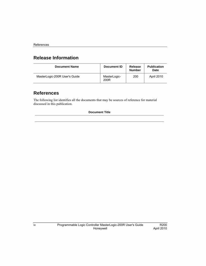
Release Information
Document Name Document ID Release Number
Publication Date
MasterLogic-200R User's Guide MasterLogic-200R
200 April 2010
References The following list identifies all the documents that may be sources of reference for material discussed in this publication.
Document Title
Acronyms and Definitions
R200 Programmable Logic Controller MasterLogic-200R User's Guide v April 2010 Honeywell
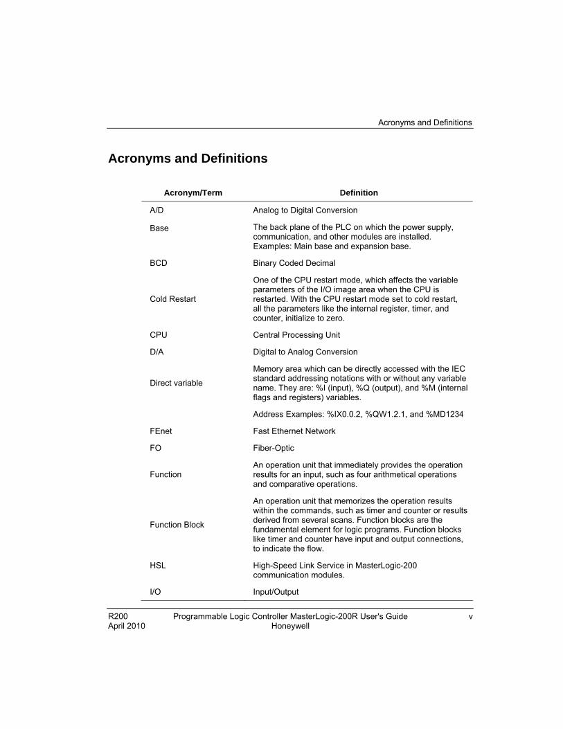
Acronyms and Definitions
Acronym/Term Definition
A/D Analog to Digital Conversion
Base
The back plane of the PLC on which the power supply, communication, and other modules are installed. Examples: Main base and expansion base.
BCD Binary Coded Decimal
Cold Restart
One of the CPU restart mode, which affects the variable parameters of the I/O image area when the CPU is restarted. With the CPU restart mode set to cold restart, all the parameters like the internal register, timer, and counter, initialize to zero.
CPU Central Processing Unit
D/A Digital to Analog Conversion
Direct variable
Memory area which can be directly accessed with the IEC standard addressing notations with or without any variable name. They are: %I (input), %Q (output), and %M (internal flags and registers) variables.
Address Examples: %IX0.0.2, %QW1.2.1, and %MD1234
FEnet Fast Ethernet Network
FO Fiber-Optic
Function An operation unit that immediately provides the operation results for an input, such as four arithmetical operations and comparative operations.
Function Block
An operation unit that memorizes the operation results within the commands, such as timer and counter or results derived from several scans. Function blocks are the fundamental element for logic programs. Function blocks like timer and counter have input and output connections, to indicate the flow.
HSL High-Speed Link Service in MasterLogic-200 communication modules.
I/O Input/Output

Acronyms and Definitions
vi Programmable Logic Controller MasterLogic-200R User's Guide R200 Honeywell April 2010
Acronym/Term Definition
I/O image area Internal memory area of CPU module installed to maintain I/O states.
IEC International Electrotechnical Commission
Interrupt Task
Interrupt driven task programs executed on meeting a given condition, in addition, to the regular scan programs. It consists of two types:
Timer Interrupt Task
Internal Flag Interrupt Task
KB Kilobyte
KStep Kilo Steps
LSB Least Significant Bit
MB Megabyte
ML-200 MasterLogic-200
Module
A standard component with a specific function to configure a system, such as the I/O board assembled that must be inserted into the base motherboard.
Examples: CPU module, power module, and I/O module.
MSB Most Significant Bit
O/S Operating System
P2P Point to Point Service in MasterLogic-200 communication modules
PAC Process Automation Controller
PLC Programmable Logic Controller
PLC System
A system consisting of a PLC, CPU, modules and peripherals configured to be controlled by a user program.
Pnet Profibus-DP Network.
RAM Random Access Memory
RTC As an abbreviation of Real Time Clock, it is collectively referred as a universal IC, with the function of a clock.
Acronyms and Definitions
R200 Programmable Logic Controller MasterLogic-200R User's Guide vii April 2010 Honeywell
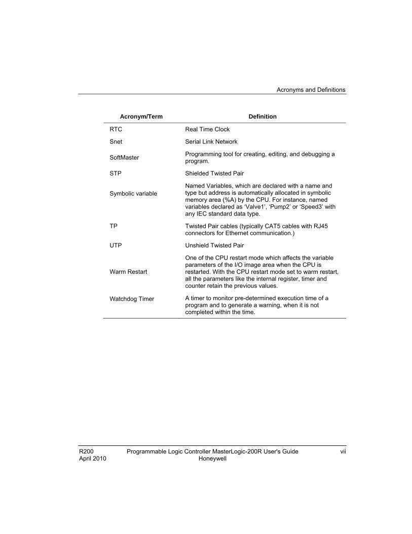
Acronym/Term Definition
RTC Real Time Clock
Snet Serial Link Network
SoftMaster Programming tool for creating, editing, and debugging a program.
STP Shielded Twisted Pair
Symbolic variable
Named Variables, which are declared with a name and type but address is automatically allocated in symbolic memory area (%A) by the CPU. For instance, named variables declared as ‘Valve1’, ‘Pump2’ or ‘Speed3’ with any IEC standard data type.
TP Twisted Pair cables (typically CAT5 cables with RJ45 connectors for Ethernet communication.)
UTP Unshield Twisted Pair
Warm Restart
One of the CPU restart mode which affects the variable parameters of the I/O image area when the CPU is restarted. With the CPU restart mode set to warm restart, all the parameters like the internal register, timer and counter retain the previous values.
Watchdog Timer
A timer to monitor pre-determined execution time of a program and to generate a warning, when it is not completed within the time.

Support and Other Contacts
viii Programmable Logic Controller MasterLogic-200R User's Guide R200 Honeywell April 2010
Support and Other Contacts
United States and Canada
Contact: Phone: Fascimile: Mail:
Honeywell Solution Support Center 1-800-822-7673 Calls are answered by dispatcher between 6:00 am and 4:00 pm Mountain Standard Time. Emergency calls outside normal working hours are received by an answering service and returned within one hour. 1-973-455-5000 Honeywell TAC, MS L17 1860 W. Garden Lane Phoenix, AZ, 85027 USA
Europe, Middle East, and Africa (EMEA)
Contact: Phone: Fascimile: Mail:
Honeywell TAC-EMEA +32-2-728-2345 +32-2-728-2696 TAC-BE02 Hermes Plaza Hermeslaan, 1H B-1831 Diegem, Belgium
Pacific
Contact: Phone: Fascimile: Mail: Email:
Honeywell Global TAC – Pacific 1300-364-822 (toll free within Australia) +61-8-9362-9559 (outside Australia) +61-8-9362-9564 Honeywell Limited Australia 5 Kitchener Way Burswood 6100, Western Australia [email protected]
India
Contact: Phone: Fascimile: Mail: Email:
Honeywell Global TAC – India +91-20- 6603-9400 +91-20- 6603-9800 Honeywell Automation India Ltd 56 and 57, Hadapsar Industrial Estate Hadapsar, Pune –411 013, India [email protected]

Support and Other Contacts
R200 Programmable Logic Controller MasterLogic-200R User's Guide ix April 2010 Honeywell
Korea
Contact: Phone: Fascimile: Mail: Email:
Honeywell Global TAC – Korea +82-2-799-6317 +82-2-792-9015 Honeywell Co., Ltd 4F, Sangam IT Tower 1590, DMC Sangam-dong, Mapo-gu Seoul, 121-836, Korea [email protected]
People’s Republic of China
Contact: Phone: Mail: Email:
Honeywell Global TAC – China +86- 21-2219-6888 800-820-0237 400-820-0386 Honeywell (China) Co., Ltd 33/F, Tower A, City Center, 100 Zunyi Rd. Shanghai 200051, People’s Republic of China [email protected]
Singapore
Contact: Phone: Fascimile: Mail: Email:
Honeywell Global TAC – South East Asia +65-6580-3500 +65-6580-3501 +65-6445-3033 Honeywell Private Limited Honeywell Building 17, Changi Business Park Central 1 Singapore 486073 [email protected]
Taiwan
Contact: Phone: Fascimile: Mail: Email:
Honeywell Global TAC – Taiwan +886-7-536-2567 +886-7-536-2039 Honeywell Taiwan Ltd. 17F-1, No. 260, Jhongshan 2nd Road. Cianjhen District Kaohsiung, Taiwan, ROC [email protected]

Support and Other Contacts
x Programmable Logic Controller MasterLogic-200R User's Guide R200 Honeywell April 2010
Japan
Contact: Phone: Fascimile: Mail: Email:
Honeywell Global TAC – Japan +81-3-6730-7160 +81-3-6730-7228 Honeywell Japan Inc. New Pier Takeshiba, South Tower Building, 20th Floor, 1-16-1 Kaigan, Minato-ku, Tokyo 105-0022, Japan [email protected]
Elsewhere
Call your nearest Honeywell office.
World Wide Web
Honeywell Solution Support Online:
http://www.honeywell.com/ps
Training Classes
Honeywell Automation College:
http://www.automationcollege.com

Symbol Definitions
R200 Programmable Logic Controller MasterLogic-200R User's Guide xi April 2010 Honeywell
Symbol Definitions The following table lists the symbols used in this document, to denote certain conditions.
Symbol Definition
ATTENTION: Identifies information that requires special consideration.
TIP: Identifies advice or hints for the user, often in terms of performing a task.
REFERENCE - EXTERNAL: Identifies an additional source of information outside of the bookset.
REFERENCE - INTERNAL: Identifies an additional source of information within the bookset.
CAUTION
Indicates a situation which, if not avoided, may result in equipment or work (data) on the system being corrupted or lost, or may result in the inability to properly operate the process.
CAUTION: Indicates a potentially hazardous situation which, if not avoided, may result in minor or moderate injury. It may also be used to alert against unsafe practices.
CAUTION symbol on the equipment refers the user to the product manual for additional information. The symbol appears next to required information in the manual.
WARNING: Indicates a potentially hazardous situation, which, if not avoided, could result in serious injury or death.
WARNING symbol on the equipment refers the user to the product manual for additional information. The symbol appears next to required information in the manual.
WARNING, Risk of electrical shock: Potential shock hazard where HAZARDOUS LIVE voltages greater than 30 Vrms, 42.4 Vpeak, or 60 VDC may be accessible.

Symbol Definitions
xii Programmable Logic Controller MasterLogic-200R User's Guide R200 Honeywell April 2010
Symbol Definition
ESD HAZARD: Danger of an electro-static discharge to which equipment may be sensitive. Observe precautions for handling electrostatic sensitive devices.
Protective Earth (PE) terminal: Provided for connection of the protective earth (green or green/yellow) supply system conductor.
Functional earth terminal: Used for non-safety purposes such as noise immunity improvement.
NOTE: This connection shall be bonded to Protective Earth at the source of supply, in accordance with the national local electrical code requirements.
Earth Ground: Functional earth connection.
NOTE: This connection shall be bonded to Protective Earth at the source of supply, in accordance with national and local electrical code requirements.
Chassis Ground: Identifies a connection to the chassis or frame of the equipment shall be bonded to Protective Earth at the source of supply in accordance with national and local electrical code requirements.

R200 Programmable Logic Controller MasterLogic-200R User's Guide xiii April 2010 Honeywell
Contents
1. INTRODUCTION ..........................................................................19
1.1 Functional overview...................................................................................... 19 Overview of MasterLogic-200R ............................................................................................19 Features ...............................................................................................................................20
2. SPECIFICATIONS........................................................................23
2.1 General specifications.................................................................................. 23
2.2 Battery ............................................................................................................ 26 Battery specifications ..........................................................................................................26 Cautions for usage ...............................................................................................................26 Battery life ............................................................................................................................26
2.3 Performance specifications ......................................................................... 27 CPU performance specifications ..........................................................................................27 Extended drive performance specifications..........................................................................31 Part names and functions – CPU .........................................................................................32 Part names and functions – extension drive.........................................................................36
2.4 Conformance to EMC specifications .......................................................... 39 EMC specifications...............................................................................................................39 Control panel........................................................................................................................40
2.5 Complying with the low-voltage directive .................................................. 43 Specifications applicable to MasterLogic-200 Series ...........................................................43 Selecting a MasterLogic-200 Series PLC.............................................................................43
3. HARDWARE – SPECIFICATIONS ..............................................45
3.1 Parts and functions....................................................................................... 45 Main base.............................................................................................................................45 Expansion base....................................................................................................................46 Power module ......................................................................................................................47
3.2 Main and expansion base ............................................................................ 48 Main base specifications ......................................................................................................48 Expansion base specifications .............................................................................................49 Synchronization cable ..........................................................................................................49 Extension cable....................................................................................................................49 Connector for extension cable..............................................................................................50

Contents
xiv Programmable Logic Controller MasterLogic-200R User's Guide R200 Honeywell April 2010
3.3 Power module ...............................................................................................51 Power module specifications ............................................................................................... 51 Example of current consumption/power calculations .......................................................... 56
4. INSTALLATION AND WIRING.................................................... 59
4.1 Installing the PLC ..........................................................................................59 Installation environment ...................................................................................................... 59 Precautions for installing/handling the PLC modules .......................................................... 62
4.2 Inserting/removing modules ........................................................................68 Inserting a module............................................................................................................... 68 Detaching modules.............................................................................................................. 69
4.3 Wiring .............................................................................................................71 Power wiring........................................................................................................................ 71 I/O device wiring.................................................................................................................. 73 Grounding .......................................................................................................................... 74 Specifications of wiring cable .............................................................................................. 75
5. FUNCTIONS OF THE CPU MODULE ......................................... 77
5.1 Self-diagnostic function ...............................................................................77 Scan Watchdog timer .......................................................................................................... 77 I/O module check ............................................................................................................... 78 Battery voltage check .......................................................................................................... 78 Error logs............................................................................................................................. 78 Troubleshooting errors ........................................................................................................ 78
5.2 Clock function................................................................................................81 Read from SoftMaster/setting.............................................................................................. 81 Clock reading by flag........................................................................................................... 82
5.3 Remote functions .........................................................................................85 Overview of remote functions .............................................................................................. 85 Types of remote operation .................................................................................................. 85 Flash memory operation mode............................................................................................ 87
5.4 Forced ON/OFF of I/O ...................................................................................90 Forced I/O setting................................................................................................................ 90 Forced On/Off processing time and processing method .................................................... 91 Direct I/O operation ............................................................................................................ 92
5.5 Viewing PLC error/event log.........................................................................93 Overview of operation history .............................................................................................. 93 Error log .............................................................................................................................. 93 Mode change log................................................................................................................. 93 Power shut down log ........................................................................................................... 93
Contents
R200 Programmable Logic Controller MasterLogic-200R User's Guide xv April 2010 Honeywell
System log ...........................................................................................................................93
5.6 Diagnosing faults of an external device .................................................... 95 Detection/classification of external device fault ....................................................................95 Example ...............................................................................................................................96
5.7 Redundant system operation mode............................................................ 97 Single CPU run mode .........................................................................................................97 Extended base detach error ................................................................................................98 Redundancy synchronization area ......................................................................................99
5.8 Setting operation of communication ........................................................ 100 Automatic master conversion .............................................................................................100 Global status variable.........................................................................................................101 ONE IP solution..................................................................................................................102
5.9 Fault mask function ................................................................................... 104 Fault mask operational overview........................................................................................104 Setting fault mask ..............................................................................................................104 Releasing fault mask .........................................................................................................104
5.10 I/O module skip function ........................................................................ 106 I/O module skip operational overview ................................................................................106 Setting and processing I/O data ........................................................................................106 Releasing skip function ......................................................................................................106
5.11 Replacing a module during operation .................................................. 108 Overview of replacing modules ..........................................................................................108 Replacing modules.............................................................................................................108 Allocating I/O address .......................................................................................................109 Program modification during operation .............................................................................109
6. CONFIGURATION .....................................................................111
6.1 System configuration ................................................................................. 111 Redundancy components list ............................................................................................111 Common components list for MasterLogic-200 ..................................................................112
6.2 Redundant configuration ........................................................................... 117 Configuring the redundant system .....................................................................................117 CPU redundancy................................................................................................................118 Power supply redundancy..................................................................................................120 I/O bus redundancy ...........................................................................................................120 Examples of redundant configuration ................................................................................122
6.3 Network system........................................................................................... 124 Inter-system network..........................................................................................................124 Local network .....................................................................................................................124 High-speed link service .....................................................................................................124
Contents
xvi Programmable Logic Controller MasterLogic-200R User's Guide R200 Honeywell April 2010
P2P service ...................................................................................................................... 124 I/O allocation method and I/O address assignment........................................................... 125
7. PROGRAM STRUCTURE AND OPERATION METHOD.......... 127
7.1 Program basics............................................................................................127 Program structure and execution ...................................................................................... 127 Program operation methods.............................................................................................. 128 Operation of instantaneous interruption ............................................................................ 132 Scan time .......................................................................................................................... 134
7.2 Program execution ......................................................................................138 Program configuration ....................................................................................................... 138 Interrupt ............................................................................................................................. 142
7.3 Operation mode ...........................................................................................153 Overview of the operation mode........................................................................................ 153 RUN mode ........................................................................................................................ 153 STOP mode....................................................................................................................... 155 DEBUG mode.................................................................................................................... 155 Changing operation mode ................................................................................................. 157
7.4 Redundant system operation .....................................................................159 Redundant operation mode............................................................................................... 159 Startup of redundant system ............................................................................................ 162
7.5 CPU memory ...............................................................................................166 Overview of CPU memory................................................................................................. 166 Program memory............................................................................................................... 166 Data memory..................................................................................................................... 166 Data retain area setting ..................................................................................................... 167 Data initialization by restart mode ..................................................................................... 168 Operation in the data retain area....................................................................................... 169 Data initialization ............................................................................................................... 170
8. MAINTENANCE......................................................................... 171
8.1 Repairs and maintenance ..........................................................................171 I/O module maintenance ................................................................................................... 171 Routine inspection............................................................................................................. 172 Periodic inspection ........................................................................................................... 172
9. TROUBLESHOOTING............................................................... 175
9.1 Introduction..................................................................................................175
9.2 Basic troubleshooting procedure ..............................................................175

Contents
R200 Programmable Logic Controller MasterLogic-200R User's Guide xvii April 2010 Honeywell
9.3 Troubleshooting.......................................................................................... 176 Basic trouble shooting procedure.......................................................................................176 Action when POWER LED is OFF .....................................................................................177 Action when WAR (Warning) LED is ON............................................................................179 Action when ERR. LED is ON ............................................................................................184 Action when RUN/STOP LED is OFF ................................................................................185 Action when I/O module does not function properly ...........................................................185 Action when writing a program to the CPU fails .................................................................188 Action when sync. cable is not installed properly ..............................................................189 Action when undesirable master switching occurs ............................................................190 Action when newly added CPU does not join redundant operation....................................191 Action when failing to switch master ..................................................................................192
9.4 Troubleshooting questionnaire ................................................................. 193 Questionnaire.....................................................................................................................193
9.5 Cases............................................................................................................ 195 Trouble types and measures of input circuit.......................................................................195 Trouble types and measures of output circuit.....................................................................196 Error codes list ...................................................................................................................199
10. APPENDIX .................................................................................205
10.1 Flag list .................................................................................................... 205 User flags ..........................................................................................................................205 System error flags ..............................................................................................................206 Standby CPU flag...............................................................................................................208 Master CPU error flags ......................................................................................................210 Standby CPU error flag .....................................................................................................212 System warning flags (master CPU) ..................................................................................212 System warning flags (standby CPU).................................................................................214 Communication warning flags (Master CPU) .....................................................................215 Communication warning flags (standby CPU)....................................................................216 System operation flags (master CPU)................................................................................216 System operation flags (Standby CPU)..............................................................................220 Redundant operation flags .................................................................................................222 Calculation error flags ........................................................................................................223 Operation mode key switch ................................................................................................223
10.2 Link flags (L) list ...................................................................................... 225 Communication flag list according to high-speed link number............................................225 Communication flag list according to P2P service setting ..................................................227
10.3 Communication flags (P2P) list.............................................................. 229 Link register list according to P2P number .........................................................................229
10.4 Reserved words....................................................................................... 232

Contents
xviii Programmable Logic Controller MasterLogic-200R User's Guide R200 Honeywell April 2010
R200 Programmable Logic Controller MasterLogic-200R User's Guide 19 April 2010 Honeywell
1. Introduction
1.1 Functional overview
Overview of MasterLogic-200R
MasterLogic-200R provides redundant configuration required in various applications. Using the same resources as MasterLogic-200 IEC CPU, you can easily configure the redundant system. This document lists the specifications, and the procedures for installing, handling, configuring, and programming the redundant system.
Redundancy types
The MasterLogic-200R offers the following types of redundancy.
Redundant CPU
Redundant Power Supply
Redundant module
Redundant Module consists of following:
Two Redundant CPUs (CAT5 and Fiber Optic).
Four Redundant Power Supplies (Standard and Enhanced) – AC100V, AC220V, and DC24V.
Redundant Main Base (6 Slots: Allows six communication modules).
Three Extension Drive Modules (CAT5, Fiber Optic, and Hybrid).
CPU module
CPU Module consists of: IEC 61131-3 Language Support, Ladder Execution Speed of 42ns per Instruction, 1MB (128kstep) Program Capacity, and 131072 I/O points.
1 Giga Fiber Optic Communication for CPU Synchronization.
Built-in Communication Master for Extension Drive.
Dedicated I/O network
Dedicated I/O network consist of: Extension Drive Module
Ring Topology (Bus Topology for single network failure)
1. Introduction 1.1. Functional overview
20 Programmable Logic Controller MasterLogic-200R User's Guide R200 Honeywell April 2010
Fiber Optic, CAT5, and Hybrid Media
100Mbps Industrial Ethernet Technology
Maximum I/O point : 23808 points (31 stations x 12 slots x 64 points)
Programming tool
Programming tool consists of following:
SoftMaster for all MasterLogic PLC (ML50, ML200, ML200 IEC, and ML200R)
IEC 61131-3 Language Support : LD, ST, SFC, and IL (View only)
Features
High-speed processing
CPU Process Time : 42ns/Step (ML200R)
High-Speed Back-Plane Speed : 20MB/s
Maximum Control points: 131072 points
Program Capacity: 7MB (including Upload, Parameter, System area)
Long data type (64 bit) and high-speed real number operation (Single and Double)
Switchover in minimum time: When errors occur, Master CPU Module Switchover happens within 50ms
Compact size
Compact size enables compact cabinet size
CPU Module: 55mm x 98mm x 90mm (W x H x D)
Power Supply Module: 55mm x 98mm x 90mm (W x H x D)
Easy installation with network based extension
Base extension with network cable
Maximum 31 extension bases
USB connection on extension base for program upload/download
Communication Master module for Modbus and Profibus.

1. Introduction 1.1. Functional overview
R200 Programmable Logic Controller MasterLogic-200R User's Guide 21 April 2010 Honeywell
Easy maintenance with System Logs and Network Ring Topology
System analysis with operation log, system log, and error log
Single fault tolerant ethernet for network cable failure with network ring topology
Network Monitoring and Protocol Monitoring
Graphical monitoring of System Configuration
Module Changing Wizard for module exchange during operation
Various communication features
Easy interface with open protocol (Profibus and Modbus)
24 Communication Master Module in extension base
Network diagnosis with network and frame monitoring
Peer-to-peer communication between MasterLogic PLCs
Various types of digital I/O modules
Around 8, 16, 32, 64 Input and Output Module (8 and 16 for Relay type)
Enhanced analog features
Analog Output: Maximum Modules = 300, Maximum Points: 3008 = 2400 (includes memory restriction).
Analog Input: Maximum Modules = 372, Maximum Points: 3728 = 2972 (not including AI 16 channel as it is not officially released).
Isolated Analog modules and temperature sensing module for improved accuracy.
Easy use of special parameter and flags.
Enhanced Debugging function flag and data monitor, setting value modification by Special Monitor Window.
Other Features
Program battery and flash memory backup
Supports two restart modes (Warm and Cold)
Management of task program
1. Introduction 1.1. Functional overview
22 Programmable Logic Controller MasterLogic-200R User's Guide R200 Honeywell April 2010
Input/output forced ON/OFF
Clock function
Module switch on operation
Fault mask function
Module skip function
Support operation log widely (System Log)
Support detailed error factor (Error Log)
LED Indication function : Operating information indication
PID Function
Maximum 256 PID loops supported.
Parameter setting using SoftMaster and Convenient Loop State monitoring through Trend Monitor.
Easy configuration of Control Constants by improved Auto Tuning Function.
Available Forward/Reverse Mixed Operation, support variety control modes like SV PID Control (2 Stages), CASCADE Control, and so on.
Guarantee for stability like PV MAX, PV Change alarm, and so on.
R200 Programmable Logic Controller MasterLogic-200R User's Guide 23 April 2010 Honeywell
2. Specifications
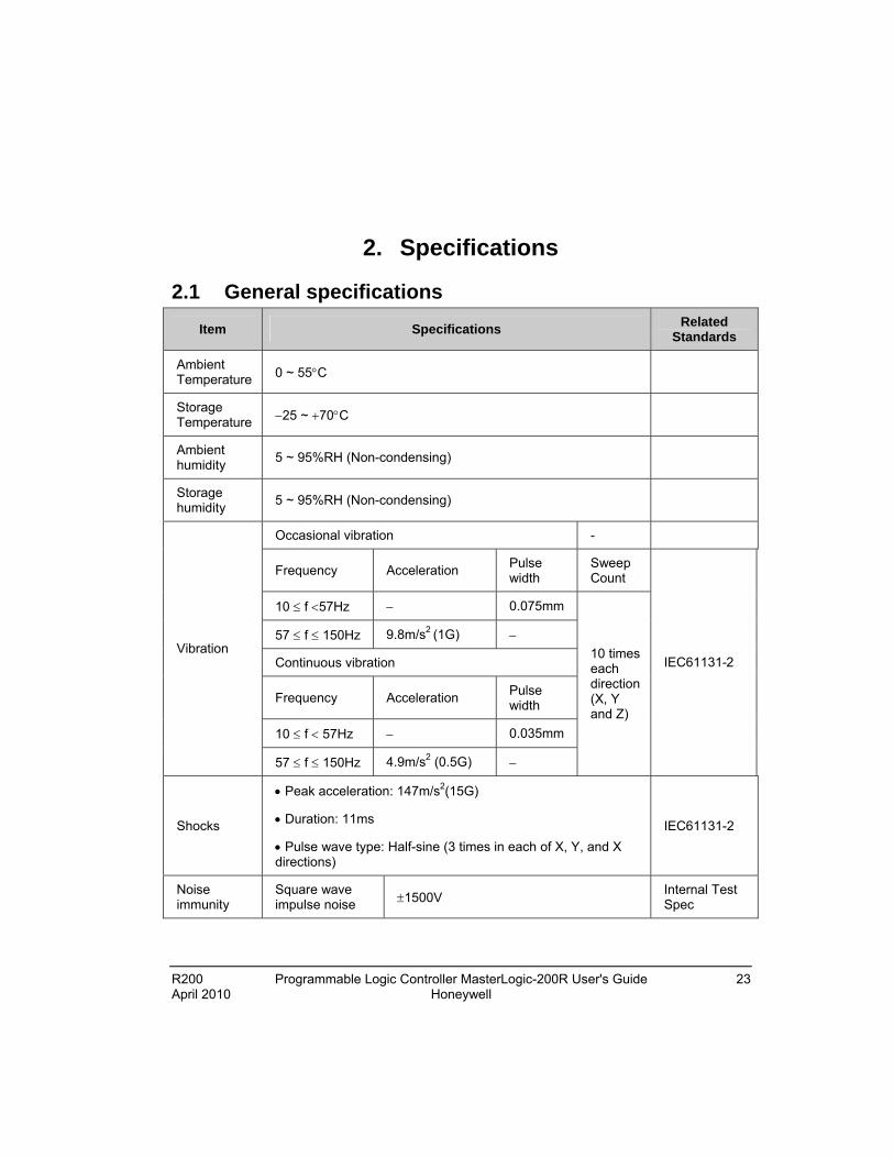
2.1 General specifications
Item Specifications Related
Standards
Ambient Temperature 0 ~ 55C
Storage Temperature 25 ~ 70C
Ambient humidity
5 ~ 95%RH (Non-condensing)
Storage humidity
5 ~ 95%RH (Non-condensing)
Occasional vibration -
Frequency Acceleration Pulse width
Sweep Count
10 f 57Hz 0.075mm
57 f 150Hz 9.8m/s2 (1G)
Continuous vibration
Frequency Acceleration Pulse width
10 f 57Hz 0.035mm
Vibration
57 f 150Hz 4.9m/s2 (0.5G)
10 times each direction (X, Y and Z)
IEC61131-2
Shocks
Peak acceleration: 147m/s2(15G)
Duration: 11ms
Pulse wave type: Half-sine (3 times in each of X, Y, and X directions)
IEC61131-2
Noise immunity
Square wave impulse noise 1500V
Internal Test Spec
2. Specifications 2.1. General specifications
24 Programmable Logic Controller MasterLogic-200R User's Guide R200 Honeywell April 2010
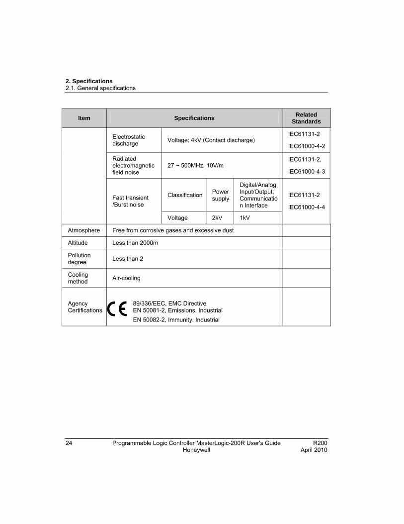
Item Specifications Related
Standards
Electrostatic discharge
Voltage: 4kV (Contact discharge) IEC61131-2
IEC61000-4-2
Radiated electromagnetic field noise
27 ~ 500MHz, 10V/m IEC61131-2,
IEC61000-4-3
Classification Power supply
Digital/Analog Input/Output, Communication Interface
Fast transient /Burst noise
Voltage 2kV 1kV
IEC61131-2
IEC61000-4-4
Atmosphere Free from corrosive gases and excessive dust
Altitude Less than 2000m
Pollution degree
Less than 2
Cooling method
Air-cooling
Agency Certifications
89/336/EEC, EMC Directive EN 50081-2, Emissions, Industrial
EN 50082-2, Immunity, Industrial

2. Specifications 2.1. General specifications
R200 Programmable Logic Controller MasterLogic-200R User's Guide 25 April 2010 Honeywell
ATTENTION
IEC (International Electrotechnical Commission) – Is an international civil community that promotes international cooperation for the standardization of electric/electro technology. It publishes international standards and operates the related suitability assessment system.
Pollution Degree – Is an index to indicate the pollution degree of used environment that determines the isolation performance of the device. For example, pollution degree two means the state to occur the pollution of non-electric conductivity, but the state to occur temporary electric conduction, according to the formation of dew.
Compliance to European Union Directives. This product has the CE mark and is approved for installation within the European Union and EEA regions. It is designed and tested to meet the following directives.
EMC Directive – This apparatus is tested to meet Council Directive 89/ 336/ EEC Electromagnetic Compatibility (EMC), using a technical construction file and the following standards, in whole or in part.
EN 50081- 2 EMC – Generic Emission Standard, and Part 2 – Industrial Environment
EN 50082- 2 EMC – Generic Immunity Standard, and Part 2 – Industrial Environment
The product described in this document is intended for use in an industrial environment.
Low-Voltage Directive. This product is also designed to meet the Council Directive 73/ 23/ EEC Low Voltage, by applying the safety requirements of EN 61131– 2 Programmable Controllers, Part 2 – Equipment Requirements and Tests.
2. Specifications 2.2. Battery
26 Programmable Logic Controller MasterLogic-200R User's Guide R200 Honeywell April 2010
2.2 Battery
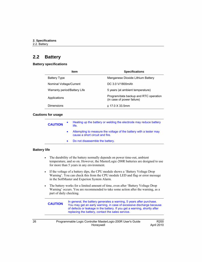
Battery specifications
Item Specifications
Battery Type Manganese Dioxide Lithium Battery
Nominal Voltage/Current DC 3.0 V/1800mAh
Warranty period/Battery Life 5 years (at ambient temperature)
Applications Program/data backup and RTC operation (in case of power failure)
Dimensions 17.0 X 33.5mm
Cautions for usage
CAUTION
Heating up the battery or welding the electrode may reduce battery life.
Attempting to measure the voltage of the battery with a tester may cause a short circuit and fire.
Do not disassemble the battery.
Battery life
The durability of the battery normally depends on power time-out, ambient temperature, and so on. However, the MasterLogic-200R batteries are designed to use for more than 5 years in any environment.
If the voltage of a battery dips, the CPU module shows a ‘Battery Voltage Drop Warning’. You can check this from the CPU module LED and flag or error message in the SoftMaster and Experion System Alarm.
The battery works for a limited amount of time, even after ‘Battery Voltage Drop Warning’ occurs. You are recommended to take some action after the warning, as a part of daily checking.
CAUTION
In general, the battery generates a warning, 5 years after purchase. You may get an early warning, in case of excessive discharge because of defects or leakage in the battery. If you get a warning, shortly after replacing the battery, contact the sales service.
2. Specifications 2.3. Performance specifications
R200 Programmable Logic Controller MasterLogic-200R User's Guide 27 April 2010 Honeywell
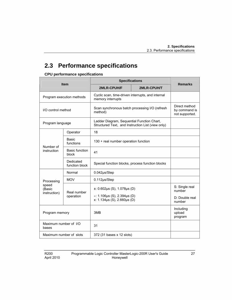
2.3 Performance specifications CPU performance specifications
Specifications Item
2MLR-CPUH/F 2MLR-CPUH/T Remarks
Program execution methods Cyclic scan, time-driven interrupts, and internal memory interrupts
I/O control method Scan synchronous batch processing I/O (refresh method)
Direct method by command is not supported.
Program language Ladder Diagram, Sequential Function Chart, Structured Text, and Instruction List (view only)
Operator 18
Basic functions
130 + real number operation function
Basic function block
41
Number of instruction
Dedicated function block
Special function blocks, process function blocks
Normal 0.042µs/Step
MOV 0.112µs/Step Processing speed (Basic instruction) Real number
operation
±: 0.602µs (S), 1.078µs (D)
: 1.106µs (S), 2.394µs (D) x: 1.134µs (S), 2.660µs (D)
S: Single real number
D: Double real number
Program memory 3MB Including upload program
Maximum number of I/O bases
31
Maximum number of slots 372 (31 bases x 12 slots)
2. Specifications 2.3. Performance specifications
28 Programmable Logic Controller MasterLogic-200R User's Guide R200 Honeywell April 2010
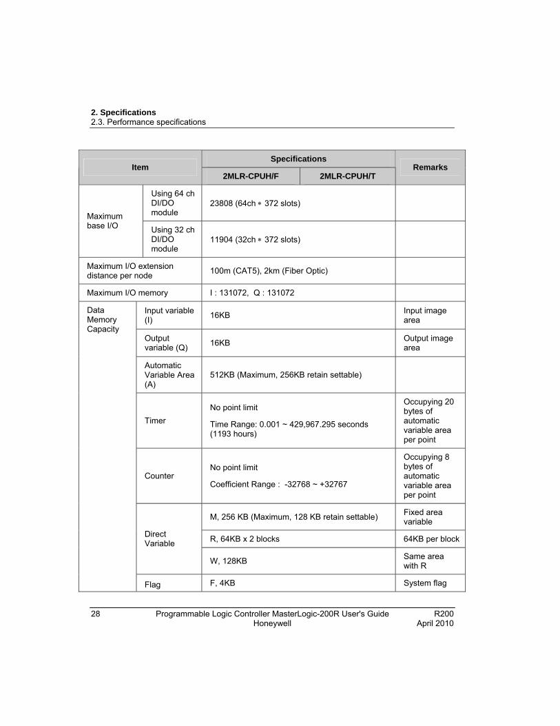
Specifications Item
2MLR-CPUH/F 2MLR-CPUH/T Remarks
Using 64 ch DI/DO module
23808 (64ch 372 slots)
Maximum base I/O Using 32 ch
DI/DO module
11904 (32ch 372 slots)
Maximum I/O extension distance per node
100m (CAT5), 2km (Fiber Optic)
Maximum I/O memory I : 131072, Q : 131072
Input variable (I)
16KB Input image area
Output variable (Q)
16KB Output image area
Automatic Variable Area (A)
512KB (Maximum, 256KB retain settable)
Timer
No point limit
Time Range: 0.001 ~ 429,967.295 seconds (1193 hours)
Occupying 20 bytes of automatic variable area per point
Counter No point limit
Coefficient Range : -32768 ~ +32767
Occupying 8 bytes of automatic variable area per point
M, 256 KB (Maximum, 128 KB retain settable) Fixed area variable
R, 64KB x 2 blocks 64KB per block Direct Variable
W, 128KB Same area with R
Data Memory Capacity
Flag F, 4KB System flag

2. Specifications 2.3. Performance specifications
R200 Programmable Logic Controller MasterLogic-200R User's Guide 29 April 2010 Honeywell
Specifications Item
2MLR-CPUH/F 2MLR-CPUH/T Remarks
K, 18KB (PID 256 loops) PID flag
L, 22KB High-speed link flag
N, 42KB P2P flag
U, 32KB (31 base, 16 slots, and 32 channels) Analog refresh flag as VAR_GLOBAL
Variables
INIT task 1 max
Timer Interrupt tasks
32 max
Internal Device Interrupt tasks
32 max
Scan program Balance: 256 minus sum of above
Program Type Allocation
Total 256 max
CPU operation mode RUN, STOP, DEBUG
CPU restart mode Cold or Warm restart
Self-diagnosis Watchdog timer, memory error, I/O error, battery error, power error, communication error, and so on.
RS-232C(1CH)
USB (1CH) @ 12MBPS
Modbus slave supported through RS-232C port Built-in Program port
Note: Additional program connections through Ethernet and serial communication module (local or remote)
2. Specifications 2.3. Performance specifications
30 Programmable Logic Controller MasterLogic-200R User's Guide R200 Honeywell April 2010
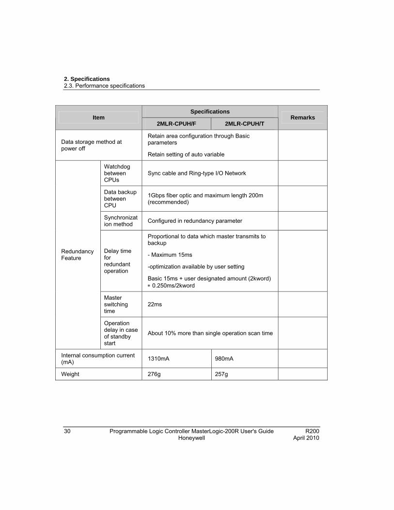
Specifications Item
2MLR-CPUH/F 2MLR-CPUH/T Remarks
Data storage method at power off
Retain area configuration through Basic parameters
Retain setting of auto variable
Watchdog between CPUs
Sync cable and Ring-type I/O Network
Data backup between CPU
1Gbps fiber optic and maximum length 200m (recommended)
Synchronization method
Configured in redundancy parameter
Delay time for redundant operation
Proportional to data which master transmits to backup
- Maximum 15ms
-optimization available by user setting
Basic 15ms + user designated amount (2kword) 0.250ms/2kword
Master switching time
22ms
Redundancy Feature
Operation delay in case of standby start
About 10% more than single operation scan time
Internal consumption current (mA)
1310mA 980mA
Weight 276g 257g

2. Specifications 2.3. Performance specifications
R200 Programmable Logic Controller MasterLogic-200R User's Guide 31 April 2010 Honeywell
Extended drive performance specifications
Specification
Items 100BASE-FX 100BASE-TX
Transmission method Base band
Maximum extension distance between nodes
2km 100m
Maximum number of nodes 31
Maximum protocol size 1516 byte
Communication access method
CSMA/CD
Frame error check
method
CRC 32 = X32 + X26 + X23+ ,,,,, + X2 + X + 1
Transmission Specification
Maximum mounted number 30
Cable Multi-mode fiber FTP / STP / SFTP
Transmission speed 100Mbps
Flow control Full duplex
Communication port 2 isolated ports
Communication Media
Auto crossover Cross/direct cable is supported
(Recommend : cross cable)
Network Topology Ring, Line(Bus)
Ring Line(Bus) 10ms Conversion
Time Line(Bus) Ring 500ms
Dimensions(mm) 98(H) X 27(W) X 90(D)
Current consumption (mA) DBSF : 850 / DBSH : 660 / DBST : 490
Basic Specification
Weight (g) DBSF : 102 / DBSH : 101 / DBST : 99
2. Specifications 2.3. Performance specifications
32 Programmable Logic Controller MasterLogic-200R User's Guide R200 Honeywell April 2010
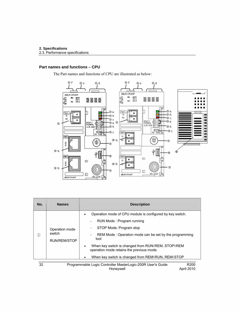
Part names and functions – CPU
The Part names and functions of CPU are illustrated as below:
No. Names Description
①
Operation mode switch
RUN/REM/STOP
Operation mode of CPU module is configured by key switch.
RUN Mode : Program running
STOP Mode: Program stop
REM Mode : Operation mode can be set by the programming tool
When key switch is changed from RUNREM, STOPREM operation mode retains the previous mode.
When key switch is changed from REMRUN, REMSTOP

2. Specifications 2.3. Performance specifications
R200 Programmable Logic Controller MasterLogic-200R User's Guide 33 April 2010 Honeywell
No. Names Description
operation mode changes to the altered mode.
If key switch is not in REM mode, operation mode or program download is not allowed by the programming tool. However, monitoring and data changing are allowed.
②-a RUN/STOP LED
Shows operation status of CPU module.
Green light: ‘RUN’ mode; the module is in operation.
‘RUN’ operation by operation mode switch.
‘RUN’ operation by programming tool with operation mode switch in ‘REM’.
Red light: ‘STOP’ mode; the module is in operation.
‘STOP’ operation by operation mode switch.
‘STOP’ operation by programming tool with operation mode switch in ‘REM’.
②-b WAR LED ON(YELLOW): Warning
OFF: Normal
②-c ERR LED ON(RED): Critical Error
OFF: Normal
②-d BAT LED
Four digit display of the Operation Status (Refer to ML200R Error code)
Normal Operation
Warning
Error
②-e Displaying redundant status
RED ON: Master/Backup CPU in redundant operation.
RED OFF: Master/Backup CPU in single operation.
MASTER ON: CPU is operating as Master.
MASTER OFF: CPU is operating as Backup.
CPU classification : CPU-A and CPU-B
②-f Displaying extension
Displays communication status with expansion base.

2. Specifications 2.3. Performance specifications
34 Programmable Logic Controller MasterLogic-200R User's Guide R200 Honeywell April 2010
No. Names Description
network status ACT ON (YELLOW): Channel is in operation.
LNK ON (GREEN): Channel link is enabled.
Channel 1 : ②-a and Channel 2 : ②-b
RING ON (GREEN): Ring topology is established in expansion network.
RING OFF: Ring topology is interrupted and runs in a bus condition or network is not established.
③ Sync. Connector Interface connector between CPUs for monitoring and data sharing.
④-a
④-b
Connector for extension connector
Connector for expansion base
Two connectors for ring topology.
Two type of CPU for fiber optic and twist pair cable connection.
⑤-a BOOT/NORMAL switch
O/S Download
ON(Right) : Normal Operation
OFF (Left): You must not use.
(O/S Download mode)
Caution: Boot/Nor switch must be in ON condition. OFF mode may cause damage to modules.
⑤-b A/B side switch (CPU position designation switch)
Switch to define CPU classification
CPU module is ‘A’, if the switch is set to the left.
CPU module is ‘B’, if the switch is set to the right.
Two CPU must have different settings (you can check it using software).
A same setting does not affect operation but may not operate in a normal way.
⑤-c Reset/D. Clear switch
Resets CPU when switch is set to the left.
Left → Center: RESET
Left → more than 3s → Center: Overall RESET

2. Specifications 2.3. Performance specifications
R200 Programmable Logic Controller MasterLogic-200R User's Guide 35 April 2010 Honeywell
No. Names Description
Clears data when switch is set to the right.
Right → Center: clears memory area for M, auto-allocated retain, general data memory address.
Right → more than 3s → Center: Clears memory area for M, auto-allocated retain, General Data Memory Address and R Area
Caution: Data clear is only performed in ‘STOP’ mode.
⑥ USB Connector Connection with Software (USB 1.1)
⑦ RS232C Connector
Connection with other device
SoftMaster connection
⑧ Battery Cover Cover for backup battery
2. Specifications 2.3. Performance specifications
36 Programmable Logic Controller MasterLogic-200R User's Guide R200 Honeywell April 2010
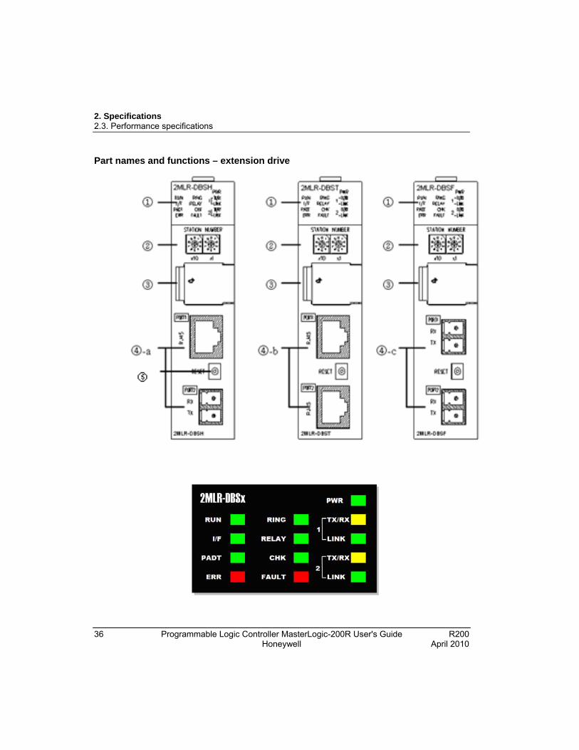
Part names and functions – extension drive
2. Specifications 2.3. Performance specifications
R200 Programmable Logic Controller MasterLogic-200R User's Guide 37 April 2010 Honeywell
No. Names Description
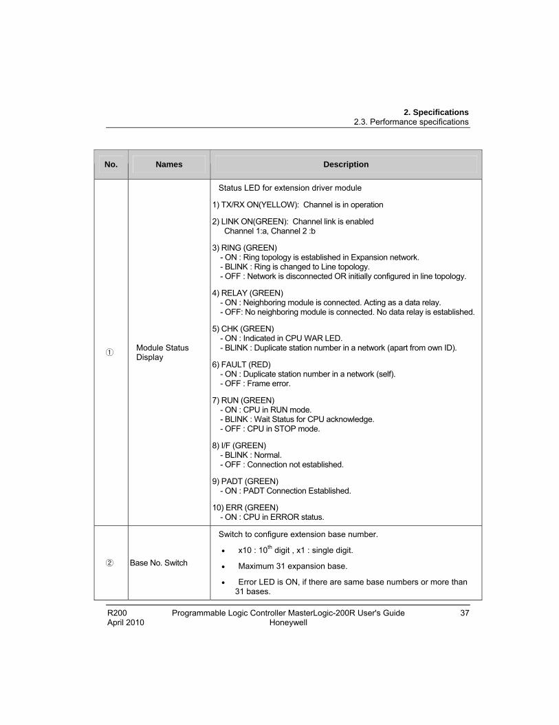
① Module Status Display
Status LED for extension driver module
1) TX/RX ON(YELLOW): Channel is in operation
2) LINK ON(GREEN): Channel link is enabled Channel 1:a, Channel 2 :b
3) RING (GREEN) - ON : Ring topology is established in Expansion network. - BLINK : Ring is changed to Line topology. - OFF : Network is disconnected OR initially configured in line topology.
4) RELAY (GREEN) - ON : Neighboring module is connected. Acting as a data relay. - OFF: No neighboring module is connected. No data relay is established.
5) CHK (GREEN) - ON : Indicated in CPU WAR LED. - BLINK : Duplicate station number in a network (apart from own ID).
6) FAULT (RED) - ON : Duplicate station number in a network (self). - OFF : Frame error.
7) RUN (GREEN) - ON : CPU in RUN mode. - BLINK : Wait Status for CPU acknowledge. - OFF : CPU in STOP mode.
8) I/F (GREEN) - BLINK : Normal. - OFF : Connection not established.
9) PADT (GREEN) - ON : PADT Connection Established.
10) ERR (GREEN) - ON : CPU in ERROR status.
② Base No. Switch
Switch to configure extension base number.
x10 : 10th digit , x1 : single digit.
Maximum 31 expansion base.
Error LED is ON, if there are same base numbers or more than 31 bases.
2. Specifications 2.3. Performance specifications
38 Programmable Logic Controller MasterLogic-200R User's Guide R200 Honeywell April 2010
No. Names Description
③ USB Connector Connection with software (USB 1.1).
④ Connector for Expansion Network
Connector for expansion base.
Two connectors.
Three types of expansion module for fiber optic, twist pair cable, and hybrid connection.
⑤ Reset Switch for Expansion Driver Module
Resets expansion driver module.
Required when individual module must be reset.
Base must be skipped before the module is reset.
If the base is not skipped before reset, disconnection error occurs.
If base is not skipped before reset, module detach error occurs.
2. Specifications 2.4. Conformance to EMC specifications
R200 Programmable Logic Controller MasterLogic-200R User's Guide 39 April 2010 Honeywell
2.4 Conformance to EMC specifications
EMC specifications
The EMC Directive specifies that products must ‘be so constructed that they do not cause excessive electromagnetic interference (emissions) and are not unduly affected by electromagnetic interference (immunity)’. The applicable products are expected to meet these requirements.
This section summarizes the precautions for the MasterLogic-200 PLC to ensure conformance to the EMC Directive. Details of these precautions are based on the requirements and the applicable standards. However, Honeywell does not guarantee that the overall system manufactured according to these details conforms to the directives listed in the following table.
The method of conformance to the EMC directive and the judgment on whether the system conforms to the EMC Directive must be finally determined by the manufacturer of the system.
The standards applicable to the EMC Directive are as follows:
Specification Test Items Test Details Standard Value
EN55011 Radiated noise 2
Measure the wave that a product emits.
30~230 MHz QP : 50dBV/m 1
230~1000 MHz QP : 57 dBV/m
EN50081-2 EN55011 conducted noise
Measure the noise that a product emits to the power line.
150~500 kHz QP : 79dBMean : 66dB
500~230 MHz QP : 73 dB Mean : 60dB
EN61000-4- Electrostatic immunity
Immunity test allowing static electricity to the case of a device.
15kV Air discharge
8 kV Contact discharge EN61131-2
EN61000-4-4
Fast transient burst noise
Immunity test allowing a fast noise to the power cable and signal cable.
Power line : 2kV
Digital I/O : 1kV
Analog I/O, signal lines : 1kV
2. Specifications 2.4. Conformance to EMC specifications
40 Programmable Logic Controller MasterLogic-200R User's Guide R200 Honeywell April 2010
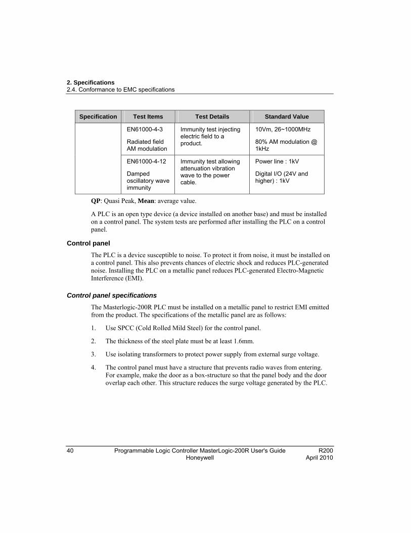
Specification Test Items Test Details Standard Value
EN61000-4-3
Radiated field AM modulation
Immunity test injecting electric field to a product.
10Vm, 26~1000MHz
80% AM modulation @ 1kHz
EN61000-4-12
Damped oscillatory wave immunity
Immunity test allowing attenuation vibration wave to the power cable.
Power line : 1kV
Digital I/O (24V and higher) : 1kV
QP: Quasi Peak, Mean: average value.
A PLC is an open type device (a device installed on another base) and must be installed on a control panel. The system tests are performed after installing the PLC on a control panel.
Control panel
The PLC is a device susceptible to noise. To protect it from noise, it must be installed on a control panel. This also prevents chances of electric shock and reduces PLC-generated noise. Installing the PLC on a metallic panel reduces PLC-generated Electro-Magnetic Interference (EMI).
Control panel specifications
The Masterlogic-200R PLC must be installed on a metallic panel to restrict EMI emitted from the product. The specifications of the metallic panel are as follows:
1. Use SPCC (Cold Rolled Mild Steel) for the control panel.
2. The thickness of the steel plate must be at least 1.6mm.
3. Use isolating transformers to protect power supply from external surge voltage.
4. The control panel must have a structure that prevents radio waves from entering. For example, make the door as a box-structure so that the panel body and the door overlap each other. This structure reduces the surge voltage generated by the PLC.
2. Specifications 2.4. Conformance to EMC specifications
R200 Programmable Logic Controller MasterLogic-200R User's Guide 41 April 2010 Honeywell
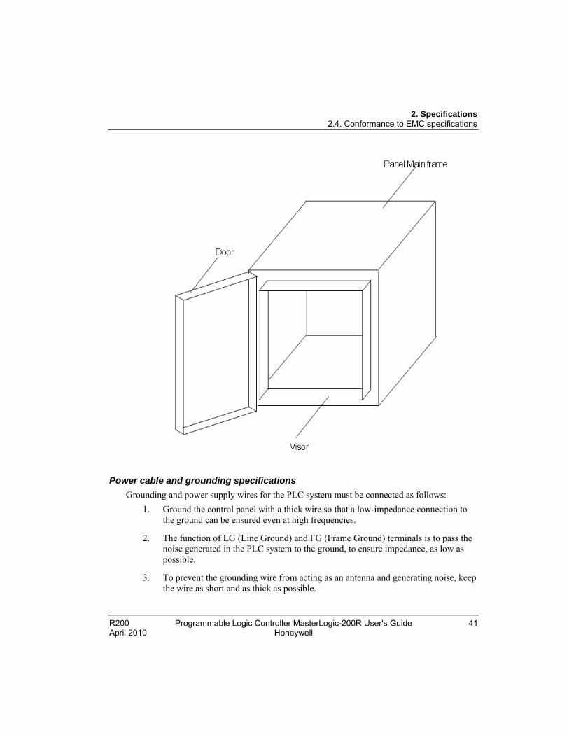
Power cable and grounding specifications
Grounding and power supply wires for the PLC system must be connected as follows:
1. Ground the control panel with a thick wire so that a low-impedance connection to the ground can be ensured even at high frequencies.
2. The function of LG (Line Ground) and FG (Frame Ground) terminals is to pass the noise generated in the PLC system to the ground, to ensure impedance, as low as possible.
3. To prevent the grounding wire from acting as an antenna and generating noise, keep the wire as short and as thick as possible.
2. Specifications 2.4. Conformance to EMC specifications
42 Programmable Logic Controller MasterLogic-200R User's Guide R200 Honeywell April 2010
Fixing a cable in the panel
While connecting an extension to the metal panel, maintain a space of at least 1cm from the panel. The metal board of the control panel has a shielding effect that blocks noise. If a metal panel is in contact with a cable, it could serve as an antenna and thereby be a source of noise.
CAUTION Keep all high-speed signal transmission cables at a safe distance from the metal board.
2. Specifications 2.5. Complying with the low-voltage directive
R200 Programmable Logic Controller MasterLogic-200R User's Guide 43 April 2010 Honeywell
2.5 Complying with the low-voltage directive The low-voltage directive requires each device that operates with power supply ranging from 50V to 1000VAC and 75V to 1500VDC, to satisfy the safety requirements. This section describes the precautions to ensure the installation and wiring of the MasterLogic-200 series conforms to the low-voltage directive.
WARNING
The contents of this section are based on the requirements and the applicable standards control. However, Honeywell does not guarantee that the overall machinery manufactured according to these details conforms to the low-voltage regulation.
Specifications applicable to MasterLogic-200 Series
The MasterLogic-200 series follows EN6100-1 (safety of devices used in measurement rooms, control rooms or laboratories).
The MasterLogic-200 series modules that operate at the rated voltage of AC 50V/DC 75V or above are also developed to conform to the low-voltage standards.
Selecting a MasterLogic-200 Series PLC
1. Power Module: The voltages inside the power supply modules are extremely dangerous. Peak voltage can be higher than 42.4V for the AC 110/220V rated I/O voltages. Therefore, the CE mark-compliant models are internally enhanced in isolation between the primary and secondary.
2. Digital I/O Module: The voltages inside the Digital I/O modules are extremely dangerous. Peak voltages can be higher than 42.4V for the AC 110/220V rated I/O voltages. Therefore, the CE mark-compliant models are internally enhanced in isolation between the primary and secondary. The I/O modules of DC 24V or of less rating are out of the low-voltage directive application range.
3. CPU Module, Base Unit: These modules use DC 5V and 3.3V circuits. So, they are out of the low-voltage directive application range.
4. Special Module, Communication Module: The special module and communication modules use DC 24V or less rated voltage. Therefore, they are out of the low-voltage directive application range.

2. Specifications 2.5. Complying with the low-voltage directive
44 Programmable Logic Controller MasterLogic-200R User's Guide R200 Honeywell April 2010

R200 Programmable Logic Controller MasterLogic-200R User's Guide 45 April 2010 Honeywell
3. Hardware – Specifications
3.1 Parts and functions
Main base
Index Part Function
1 Base attached guide hole For attaching the main base to the panel in the control panel.
2 Power module connector For installation of Power Supply module.
3 CPU module connector For installation of CPU module (2 slots).
4 Module built-in connector For installation of communication modules.
5 FG terminal The ground terminal connected to the shielded pattern of PCB board.

3. Hardware – Specifications 3.1. Parts and functions
46 Programmable Logic Controller MasterLogic-200R User's Guide R200 Honeywell April 2010
Expansion base
Index Part Function
1 Base attached guide hole For attaching the main base to the panel in the control panel.
2 Power module connector For installation of power supply module.
3 Extension drive module connector
For installation of extension drive module.
4 Module built-in connector
For installation of I/O, special and other communication modules.
5 FG terminal The ground terminal connected to the shielded pattern of PCB board.
3. Hardware – Specifications 3.1. Parts and functions
R200 Programmable Logic Controller MasterLogic-200R User's Guide 47 April 2010 Honeywell
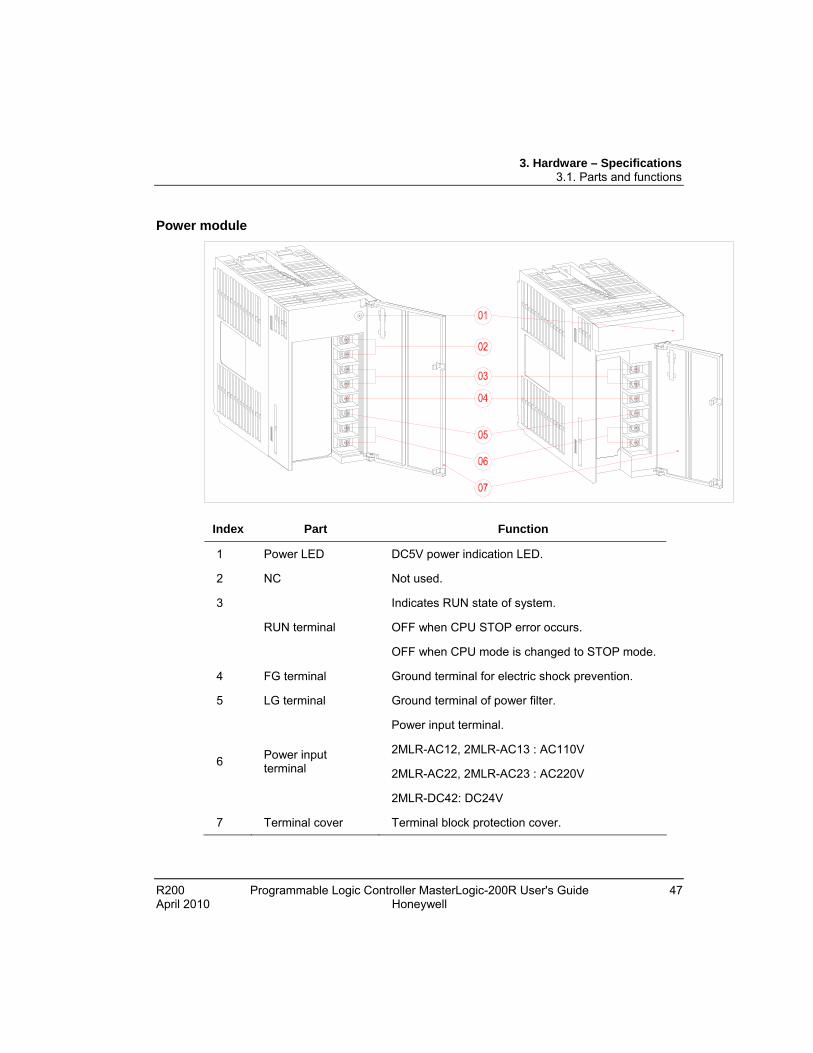
Power module
Index Part Function
1 Power LED DC5V power indication LED.
2 NC Not used.
3
RUN terminal
Indicates RUN state of system.
OFF when CPU STOP error occurs.
OFF when CPU mode is changed to STOP mode.
4 FG terminal Ground terminal for electric shock prevention.
5 LG terminal Ground terminal of power filter.
6 Power input terminal
Power input terminal.
2MLR-AC12, 2MLR-AC13 : AC110V
2MLR-AC22, 2MLR-AC23 : AC220V
2MLR-DC42: DC24V
7 Terminal cover Terminal block protection cover.
3. Hardware – Specifications 3.2. Main and expansion base
48 Programmable Logic Controller MasterLogic-200R User's Guide R200 Honeywell April 2010
3.2 Main and expansion base
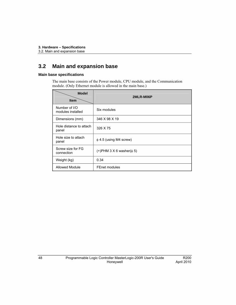
Main base specifications
The main base consists of the Power module, CPU module, and the Communication module. (Only Ethernet module is allowed in the main base.)
Model
Item 2MLR-M06P
Number of I/O modules installed
Six modules
Dimensions (mm) 346 X 98 X 19
Hole distance to attach panel
326 X 75
Hole size to attach panel 4.5 (using M4 screw)
Screw size for FG connection (+)PHM 3 X 6 washer( 5)
Weight (kg) 0.34
Allowed Module FEnet modules
3. Hardware – Specifications 3.2. Main and expansion base
R200 Programmable Logic Controller MasterLogic-200R User's Guide 49 April 2010 Honeywell
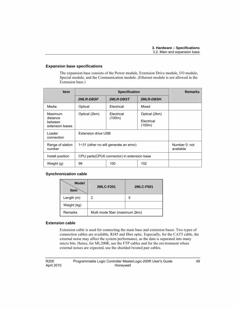
Expansion base specifications
The expansion base consists of the Power module, Extension Drive module, I/O module, Special module, and the Communication module. (Ethernet module is not allowed in the Extension base.)
Specification Item
2MLR-DBSF 2MLR-DBST 2MLR-DBSH
Remarks
Media Optical Electrical Mixed
Maximum distance between extension bases
Optical (2km) Electrical (100m)
Optical (2km)
Electrical (100m)
Loader connection
Extension drive USB
Range of station number
1~31 (other no will generate an error) Number 0: not available
Install position CPU parts(CPU0 connector) in extension base
Weight (g) 99 100 102
Synchronization cable
Model
Item 2MLC-F201 2MLC-F501
Length (m) 2 5
Weight (kg)
Remarks Multi mode fiber (maximum 2km)
Extension cable
Extension cable is used for connecting the main base and extension bases. Two types of connection cables are available, RJ45 and fiber optic. Especially, for the CAT5 cable, the external noise may affect the system performance, as the data is separated into many micro bits. Hence, for ML200R, use the FTP cables and for the environment where external noises are expected, use the shielded twisted pair cables.

3. Hardware – Specifications 3.2. Main and expansion base
50 Programmable Logic Controller MasterLogic-200R User's Guide R200 Honeywell April 2010
CAUTION 1) Keep the fiber optic cable within 2km between the nodes.
2) Keep the CAT5 cable within 100m between the nodes.
Connector for extension cable
RJ45 extension cable should comply with EMC standards and should be FTP/STP/SFTP type. Use the following plug and fixed housing for the shield cable.
1) Connector plug
Type: RJ45 PLUG / INDUSTRIAL CAT6 (44915-0021)
2) Plug
Type (FTP): RJ45 PLUG protection cover (WRJ45-0702)
Type (STP/SFTP): RJ45 PLUG protection cover (WRJ45-0701)
3. Hardware – Specifications 3.3. Power module
R200 Programmable Logic Controller MasterLogic-200R User's Guide 51 April 2010 Honeywell
3.3 Power module
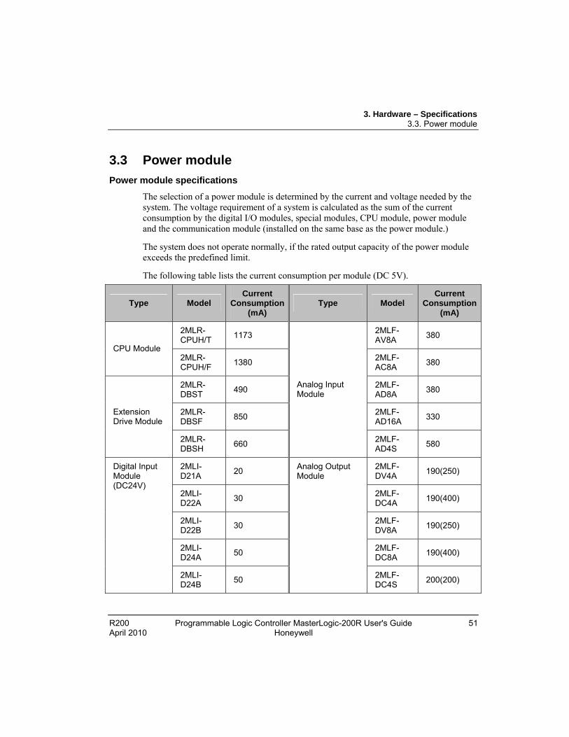
Power module specifications
The selection of a power module is determined by the current and voltage needed by the system. The voltage requirement of a system is calculated as the sum of the current consumption by the digital I/O modules, special modules, CPU module, power module and the communication module (installed on the same base as the power module.)
The system does not operate normally, if the rated output capacity of the power module exceeds the predefined limit.
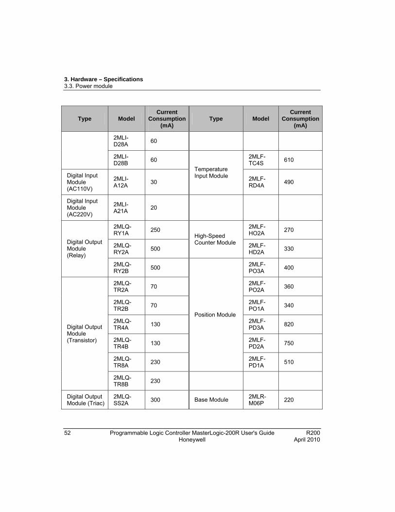
The following table lists the current consumption per module (DC 5V).
Type Model Current
Consumption (mA)
Type Model Current
Consumption (mA)
2MLR-CPUH/T
1173 2MLF-AV8A
380
CPU Module 2MLR-CPUH/F
1380 2MLF-AC8A
380
2MLR-DBST
490 2MLF-AD8A
380
2MLR-DBSF
850 2MLF-AD16A
330 Extension Drive Module
2MLR-DBSH
660
Analog Input Module
2MLF-AD4S
580
2MLI-D21A
20 2MLF-DV4A
190(250)
2MLI-D22A
30 2MLF-DC4A
190(400)
2MLI-D22B
30 2MLF-DV8A
190(250)
2MLI-D24A
50 2MLF-DC8A
190(400)
Digital Input Module (DC24V)
2MLI-D24B
50
Analog Output Module
2MLF-DC4S
200(200)
3. Hardware – Specifications 3.3. Power module
52 Programmable Logic Controller MasterLogic-200R User's Guide R200 Honeywell April 2010
Type Model Current
Consumption (mA)
Type Model Current
Consumption (mA)
2MLI-D28A
60
2MLI-D28B
60 2MLF-TC4S
610
Digital Input Module (AC110V)
2MLI-A12A
30
Temperature Input Module 2MLF-
RD4A 490
Digital Input Module (AC220V)
2MLI-A21A
20
2MLQ-RY1A
250 2MLF-HO2A
270
2MLQ-RY2A
500
High-Speed Counter Module 2MLF-
HD2A 330
Digital Output Module (Relay)
2MLQ-RY2B
500 2MLF-PO3A
400
2MLQ-TR2A
70 2MLF-PO2A
360
2MLQ-TR2B
70 2MLF-PO1A
340
2MLQ-TR4A
130 2MLF-PD3A
820
2MLQ-TR4B
130 2MLF-PD2A
750
2MLQ-TR8A
230
Position Module
2MLF-PD1A
510
Digital Output Module (Transistor)
2MLQ-TR8B
230
Digital Output Module (Triac)
2MLQ-SS2A
300 Base Module 2MLR-M06P
220

3. Hardware – Specifications 3.3. Power module
R200 Programmable Logic Controller MasterLogic-200R User's Guide 53 April 2010 Honeywell
Type Model Current
Consumption (mA)
Type Model Current
Consumption (mA)
2MLL-C22A
330 2MLR-E12P
220
2MLL-C42A
300 2MLL-EFMF
650 Snet Module
2MLL-CH2A
340
FEnet Module 2MLL-EFMT
420
Profibus-DP Module
2MLL-PMEA
560
Fiber Ring Module
2MLL-ESHF
1200
3. Hardware – Specifications 3.3. Power module
54 Programmable Logic Controller MasterLogic-200R User's Guide R200 Honeywell April 2010
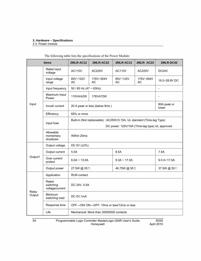
The following table lists the specifications of the Power Module:
Items 2MLR-AC12 2MLR-AC22 2MLR-AC13 2MLR- AC23 2MLR-DC42
Rated input voltage
AC110V AC220V AC110V AC220V DC24V
Input voltage range
85V~132V AC
176V~264V AC
85V~132V AC
176V~264V AC
19.2~28.8V DC
Input frequency 50 / 60 Hz (47 ~ 63Hz) -
Maximum Input Power
110VA/42W 176VA72W -
Inrush current 20 A peak or less (below 8ms ) 80A peak or lower
Efficiency 65% or more
Input fuse Built-in (Not replaceable) : AC250V/3.15A, UL standard (Time-lag Type)
DC power: 125V/10A (Time-lag type) UL approved
Input
Allowable momentary shutdown
Within 20ms
Output voltage DC 5V (±2%)
Output current 5.5A 8.5A 7.5A
Over current protect
6.0A ~ 13.0A 9.3A ~ 17.0A 9.0 A~17.0A Output1
Output power 27.5W @ 55 46.75W @ 55 37.5W @ 55
Application RUN contact
Rated switching voltage/current
DC 24V, 0.5A
Minimum switching load DC 5V,1mA
Response time OFF→ON/ ON→OFF: 10ms or less/12ms or less
Relay Output
Life Mechanical: More than 20000000 contacts

3. Hardware – Specifications 3.3. Power module
R200 Programmable Logic Controller MasterLogic-200R User's Guide 55 April 2010 Honeywell
Items 2MLR-AC12 2MLR-AC22 2MLR-AC13 2MLR- AC23 2MLR-DC42
Electrical: More than 100000 contacts at rated switching voltage/current
RUN signal output Relay output, Rating: DC24V, 0.5A
Voltage indicator Output voltage normal, LED ON
Cable specification 0.75 ~ 2mm2
Compressed terminal RAV 1.25 - 3.5, RAV 2 - 3.5
Dimension (W x H x Dmm) 55 x 95 x 90 55 x 95 x 110
Weight 326g 382g 334g 384g 417g
Applied base and install position
Power part of basic/extension base
Power part of extension base Power part of basic/extension base
ATTENTION
1. Allowable Momentary Power Failure Time: The time that input voltage keeps normal output voltage (normal operation) in the state that AC110/220V voltage is lower than the rated value (AC85 / 170V).
2. Over current protection: If the current is more than the standard and flows in DC5V, DC24V circuit, the over current protection device shuts down the circuit to stop the system. Rectify the causes, such as lack of current capacity or short circuits that leads to over current, and then restart the system.

3. Hardware – Specifications 3.3. Power module
56 Programmable Logic Controller MasterLogic-200R User's Guide R200 Honeywell April 2010
Example of current consumption/power calculations
This section describes which power supply module must be used in coordination to the corresponding modules for MasterLogic-200R.
Main base
Type Model No. Voltage (5V)
CPU Module 2MLR-CPUH/F 1 1.31A
Main Base 2MLR-M06P 1 0.2A
FEnet Module 2MLL-EFMF 6 0.61A
Current Consumption / Power Consumption
1.31A + 0.61A6 = 4.97A / 4.97×5V = 24.85W
Extension base
Type Model No. Voltage (5V)
Extension Drive
2MLR-DBSF 1 0.65A
Extension Base
2MLR-E12P 1 -
DI Module 2MLI-D24A 2 0.05A
DO Module 2MLQ-RY2A 6 0.5A
AI Module 2MLF-AD4S 2 0.61A
Profibus-DP 2MLL-PMEA 2 0.56A
Current Consumption / Power Consumption
0.65A + 0.05A2 + 0.5A6 + 0.61A2 + 0.56A2 = 6.09ª / 6.09A × 5V = 30.85 W
Sum of current consumption is 6.09. Hence, use 2MLR-AC13 or AC23.
3. Hardware – Specifications 3.3. Power module
R200 Programmable Logic Controller MasterLogic-200R User's Guide 57 April 2010 Honeywell
ATTENTION
Maximum power consumption of PLC can be derived from the efficiency of power module.
Example: Sum of 5V consumption x Minimum efficiency of Power module = 100W/0.65 = 154W.

3. Hardware – Specifications 3.3. Power module
58 Programmable Logic Controller MasterLogic-200R User's Guide R200 Honeywell April 2010

R200 Programmable Logic Controller MasterLogic-200R User's Guide 59 April 2010 Honeywell
4. Installation and Wiring
4.1 Installing the PLC
Installation environment
The PLC system is designed to withstand extreme climatic conditions. However, to ensure reliability and stability ensure that the following conditions are considered.
Environmental conditions
Dos
Install the PLC in a control panel, which is waterproof and can withstand vibration.
Install the PLC away from areas with high vibration.
Ensure an ambient temperature of 0 ~ 55C.
Ensure incremental Humidity: 5 ~ 95 %.
Don’ts
Do not expose the PLC to direct sun-light.
Do not expose the PLC to sudden changes in the temperature.
Do not expose the PLC to corrosive or inflammable gases.
Installation conditions
While drilling holes, fixing screws or wiring, ensure that no wire or any other metallic part enters the PLC.
Do not install the PLC on a panel that also has a high-voltage device.
Maintain a distance of at least 50mm from the wiring duct or surrounding modules.
Ensure the grounding at a place where surrounding noise is minimal.
Heat protection design of control panel
In case the PLC is installed in an airtight control panel, the heat protection design must be ensured, considering the radiation of other equipment, and heat from the PLC. When air circulation is provided using a vent or a general fan, the flow of dust particles or gas can hamper the functioning of the PLC system.

4. Installation and Wiring 4.1. Installing the PLC
60 Programmable Logic Controller MasterLogic-200R User's Guide R200 Honeywell April 2010
Installing a filter or use of an airtight heat exchanger is recommended.
The following figure illustrates the method used for calculating the current consumption of the PLC system necessary for heat protection design.
Power consumption of each part
1. Current consumption of power module
The current conversion efficiency of the power module is around 70 %. Radiation consumes 30%, and the current consumption is 3/7 of the output power. The calculation is as follows:
Wpw = 3/7 (I5V X 5) + (I24V X 24) (W)
I (5V) Current consumption of DC 5V circuit of each module (internal current consumption).
I (24V) Average current consumption of DC 24V of output module (current consumption of simultaneous ON point).
If DC 24V is externally supplied or a power module without DC 24V is used, it is not applicable.
2. Sum of DC 5V circuit current consumption: The DC 5V output circuit current of the power supply module is the sum of current consumption of each module.
W 5V = I5V X 5 (W)

4. Installation and Wiring 4.1. Installing the PLC
R200 Programmable Logic Controller MasterLogic-200R User's Guide 61 April 2010 Honeywell
3. DC 24V average current consumption (current consumption of simultaneous ON point): DC 24V output circuit average current of power module is the sum of current consumption of each module.
W 24V = I24V X 24 (W)
4. Average current consumption by output voltage drop of output module (current consumption of simultaneous ON point).
i. Wout = Iout X Vdrop X Output point X Simultaneous ON rate (W) ii. Iout: Output current (current in actual use) (A)
iii. Vdrop: Voltage drop of each output module (V)
5. Input average current consumption of input module (current consumption of simultaneous ON point).
i. Win = Iin X E X Input point X Simultaneous ON rate (W) ii. Iin: Input current (actual value in case of AC) (A)
iii. E: Input voltage (voltage in actual use) (V)
6. Current consumption of Special module power assembly
WS = I5V X 5 + I24V X 24 + I100V X 100 (W)
The sum of the current consumption calculated for each block is the total current consumption of PLC system.
W = WPW + W5V + W24V + Wout + Win + Ws (W)
Calculate the amount of radiation according to this total current consumption (W) and review the temperature rising in the control panel. Use the following formula for the calculation of the temperature rise in the control panel.
T = W / UA [C]
Where,
W = power consumption of the entire PLC system (the calculated value)
A = surface area of control panel [m2]
U: If equalizing the temperature of the control panel by using a fan and others
4. Installation and Wiring 4.1. Installing the PLC
62 Programmable Logic Controller MasterLogic-200R User's Guide R200 Honeywell April 2010
Precautions for installing/handling the PLC modules
Take the following precautions while handling or installing modules.
Do not drop the PLC module or apply excessive force on it.
Do not touch the PCB inside the module with bare hands, as this can lead to failure of the PLC Modules.
Ensure that external materials, such as wiring fragments do not enter the upper part of module casing. Even if such materials accidentally enter the module casing, remove them immediately.
Precautions for installing/handling I/O module
Note the following points while handling or installing the I/O module.
1. Recheck I/O module specifications
Check the input voltage for input modules. For output modules, check if the voltage applied exceeds the maximum Open/Close capacity. Over voltage may lead to failure, damage, or sparking.
2. Cable selection
Select the appropriate cable after considering its capacity to withstand temperature and intensity of current flowing through it. The minimum specification of cable must be AWG22 (0.3mm2).
3. Environment
When wiring an I/O module, ensure that it is not too close to a heat emitting equipment. In addition, avoid the wires from coming in direct contact with oil, as it may cause a short circuit, breakage, or can cause abnormal errors during operation.
4. Polarity
The polarity of the module terminals and that of the field signal must be the same.
5. Wiring
The I/O must be wired using high-voltage cables or power cables. Lower voltage wires can cause inductive disturbance that may result in abnormalities or failure of PLC operation.
Ensure that the cables do not pass in front of the I/O operation indicator (LED), as it may obstruct the indicator.
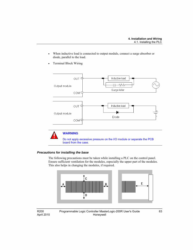
4. Installation and Wiring 4.1. Installing the PLC
R200 Programmable Logic Controller MasterLogic-200R User's Guide 63 April 2010 Honeywell
When inductive load is connected to output module, connect a surge absorber or diode, parallel to the load.
Terminal Block Wiring
WARNING
Do not apply excessive pressure on the I/O module or separate the PCB board from the case.
Precautions for installing the base
The following precautions must be taken while installing a PLC on the control panel. Ensure sufficient ventilation for the modules, especially the upper part of the modules. This also helps in changing the modules, if required.
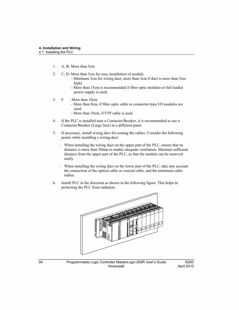
4. Installation and Wiring 4.1. Installing the PLC
64 Programmable Logic Controller MasterLogic-200R User's Guide R200 Honeywell April 2010
1. A, B: More than 5cm
2. C, D: More than 5cm for easy installation of module. - Minimum 3cm for wiring duct, more than 5cm if duct is more than 5cm high) - More than 15cm is recommended if fiber optic modules or full loaded power supply is used.
3. F : More than 10cm - More than 8cm, if fiber optic cable or connector-type I/O modules are used. - More than 10cm, if FTP cable is used.
4. If the PLC is installed near a Contactor/Breaker, it is recommended to use a Contactor/Breaker (Large Size) in a different panel.
5. If necessary, install wiring duct for routing the cables. Consider the following points while installing a wiring duct:
When installing the wiring duct on the upper part of the PLC, ensure that its distance is more than 50mm to enable adequate ventilation. Maintain sufficient distance from the upper part of the PLC, so that the module can be removed easily.
When installing the wiring duct on the lower part of the PLC, take into account the connection of the optical cable or coaxial cable, and the minimum cable radius.
6. Install PLC in the direction as shown in the following figure. This helps in protecting the PLC from radiation.

4. Installation and Wiring 4.1. Installing the PLC
R200 Programmable Logic Controller MasterLogic-200R User's Guide 65 April 2010 Honeywell
7. Do not install the PLC in the direction displayed in the following figure:
8. To avoid any effect of radiating noise or heat, install the PLC and other devices (relay and electronic contact) with a spacing secured, as indicated in the following figure.

4. Installation and Wiring 4.1. Installing the PLC
66 Programmable Logic Controller MasterLogic-200R User's Guide R200 Honeywell April 2010
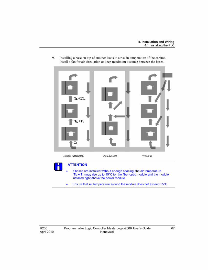
4. Installation and Wiring 4.1. Installing the PLC
R200 Programmable Logic Controller MasterLogic-200R User's Guide 67 April 2010 Honeywell
9. Installing a base on top of another leads to a rise in temperature of the cabinet. Install a fan for air circulation or keep maximum distance between the bases.
ATTENTION
If bases are installed without enough spacing, the air temperature (Tb + Tr) may rise up to 15°C for the fiber optic module and the module installed right above the power module.
Ensure that air temperature around the module does not exceed 55°C.
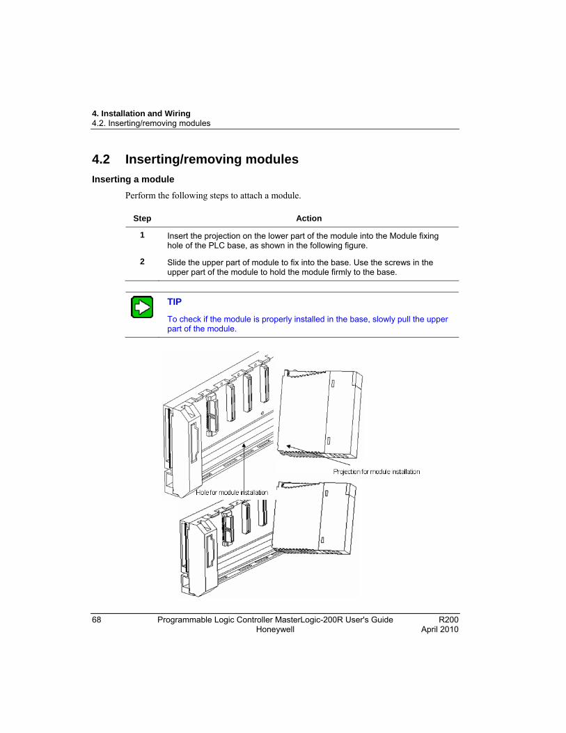
4. Installation and Wiring 4.2. Inserting/removing modules
68 Programmable Logic Controller MasterLogic-200R User's Guide R200 Honeywell April 2010
4.2 Inserting/removing modules
Inserting a module
Perform the following steps to attach a module.
Step Action
1 Insert the projection on the lower part of the module into the Module fixing hole of the PLC base, as shown in the following figure.
2 Slide the upper part of module to fix into the base. Use the screws in the upper part of the module to hold the module firmly to the base.
TIP
To check if the module is properly installed in the base, slowly pull the upper part of the module.

4. Installation and Wiring 4.2. Inserting/removing modules
R200 Programmable Logic Controller MasterLogic-200R User's Guide 69 April 2010 Honeywell
TIP
While installing modules, insert the fixed projection of the module into the module-fixing hole and then press it. The module may break, if the module is forced onto the base in an incorrect position.
Detaching modules
Perform the following steps to detach modules.
Step Action
1 From the base, loosen the fixed screws on the upper part of the module.
2 Hold the module and thoroughly press the fixed hook of the module.
3 By pressing the hook, pull the upper part of the module from the axis of the lower part.
4 By lifting the module upward, remove the fixed projection of the module from the fixing hole.

4. Installation and Wiring 4.2. Inserting/removing modules
70 Programmable Logic Controller MasterLogic-200R User's Guide R200 Honeywell April 2010
CAUTION
While detaching the module, press the hook and remove the module from the base. Then, remove the fixed projection of the module from the fixed hole of the module. If module is detached forcefully, the hook or the fixed projection of the module might break.
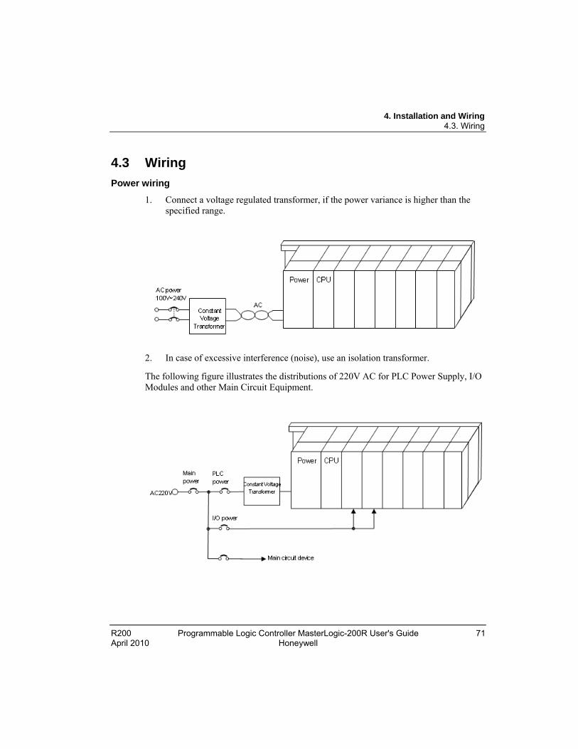
4. Installation and Wiring 4.3. Wiring
R200 Programmable Logic Controller MasterLogic-200R User's Guide 71 April 2010 Honeywell
4.3 Wiring
Power wiring
1. Connect a voltage regulated transformer, if the power variance is higher than the specified range.
2. In case of excessive interference (noise), use an isolation transformer.
The following figure illustrates the distributions of 220V AC for PLC Power Supply, I/O Modules and other Main Circuit Equipment.
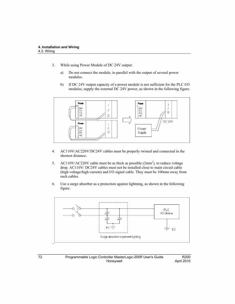
4. Installation and Wiring 4.3. Wiring
72 Programmable Logic Controller MasterLogic-200R User's Guide R200 Honeywell April 2010
3. While using Power Module of DC 24V output:
a) Do not connect the module, in parallel with the output of several power modules.
b) If DC 24V output capacity of a power module is not sufficient for the PLC I/O modules, supply the external DC 24V power, as shown in the following figure.
4. AC110V/AC220V/DC24V cables must be properly twisted and connected in the shortest distance.
5. AC110V/AC220V cable must be as thick as possible (2mm2), to reduce voltage drop. AC110V/ DC24V cables must not be installed close to main circuit cable (high voltage/high current) and I/O signal cable. They must be 100mm away from such cables.
6. Use a surge absorber as a protection against lightning, as shown in the following figure.

4. Installation and Wiring 4.3. Wiring
R200 Programmable Logic Controller MasterLogic-200R User's Guide 73 April 2010 Honeywell
TIP
1. Separate PLC earth (E2) from earth (E1) of surge absorber against lightning.
2. In case of an increase in voltage, the surge absorber ensures that it does not increase more than the predefined maximum limit.
3. Use a shielded isolation transformer or noise filter in areas where higher noise levels are expected.
4. It is advisable to use twisted cable for input power. Ensure that the shielded transformer or noise filter wiring does not pass the duct.
I/O device wiring
1. The cable used for I/O wiring must be 0.3~2.0mm2.
2. Use a separate input and output cable for wiring.
3. I/O signal cable must be separated by a distance of at least 100mm from the main circuit cable of high voltage/high current.
4. If it is not possible to separate the main circuit cable and power cable, use the shielded cable in all cases and ground the PLC.
5. In case of pipe wiring, check the pipe for grounding properly.
6. Separate output cable of DC 24V from AC 110V cable or AC 220V cable.
ATTENTION
Current leakage may take place for wiring distances longer than 200m, caused by the capacitance between the cables.

4. Installation and Wiring 4.3. Wiring
74 Programmable Logic Controller MasterLogic-200R User's Guide R200 Honeywell April 2010
Grounding
1. Sufficient measures against noise are taken in the PLC, making it possible to be used without grounding.
2. Use dedicated grounding for the wires as far as possible.
3. In case the grounding is functional, use class 3 grounding (grounding resistance must be 100Ω or less).
4. If it is not possible to use dedicated grounding, use common grounding, as depicted in the following figure.
5. Use more than 2mm2 cables for grounding. Place the earth point near the PLC as much as possible to limit the length of grounding cable.
6. Separate Line Ground (LG) of power module and Frame Ground (FG) of base board for grounding.
7. If a malfunction on grounding is detected, separate the FG of the base from the grounding.
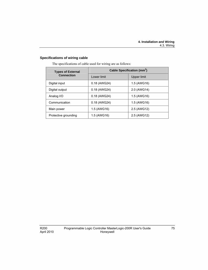
4. Installation and Wiring 4.3. Wiring
R200 Programmable Logic Controller MasterLogic-200R User's Guide 75 April 2010 Honeywell
Specifications of wiring cable
The specifications of cable used for wiring are as follows:
Cable Specification (mm2) Types of External Connection Lower limit Upper limit
Digital input 0.18 (AWG24) 1.5 (AWG16)
Digital output 0.18 (AWG24) 2.0 (AWG14)
Analog I/O 0.18 (AWG24) 1.5 (AWG16)
Communication 0.18 (AWG24) 1.5 (AWG16)
Main power 1.5 (AWG16) 2.5 (AWG12)
Protective grounding 1.5 (AWG16) 2.5 (AWG12)

4. Installation and Wiring 4.3. Wiring
76 Programmable Logic Controller MasterLogic-200R User's Guide R200 Honeywell April 2010

R200 Programmable Logic Controller MasterLogic-200R User's Guide 77 April 2010 Honeywell
5. Functions of the CPU Module
5.1 Self-diagnostic function The CPU module can perform a self-diagnosis to locate any errors in the PLC system. It can also prevent abnormal operations resulting from the error.
Scan Watchdog timer
Watchdog Timer (WDT) is a function run by the CPU module that detects program congestion through hardware and software errors of the PLC.
1. WDT is the timer, used for detecting the operation delay by user program error. The detection time of WDT is set in basic parameter using SoftMaster.
2. If WDT detects the excess of setting time during the scan while watching the operation, it stops the operation of PLC immediately, and switches off all the outputs.
3. If the excess of Scan WDT is expected during program processing of the specific part while performing the user program (FOR ~ NEXT instruction, CALL instruction), clear the timer by using ‘WDT’ instruction.
4. The ‘WDT’ instruction initializes the elapsed time of Scan WDT and starts the time measurement from 0 again.
5. Use the following method to clear the error state of watchdog.
Power reset, operation of manual reset switch.
Mode conversion to STOP mode.

5. Functions of the CPU Module 5.1. Self-diagnostic function
78 Programmable Logic Controller MasterLogic-200R User's Guide R200 Honeywell April 2010
TIP
The range of WDT is between 10 ~ 1000ms (resolution of 1ms).
I/O module check
This function is used for checking the error state of an I/O module during the beginning of an operation or during an operation.
1. In case the module installed physically is not as per the module type configured in the software (I/O parameter settings), then it shows an error.
2. In case the I/O module is removed or error occurs during operation, the error is detected and indicated by the warning lamp (ERR) and the CPU module ceases to operate.
Battery voltage check
The CPU module is capable of detecting a battery voltage drop below the memory backup voltage. On detecting a low-battery level, the low-battery warning lamp (BAT), located at the front of the CPU module glows.
Error logs
The CPU module has a function that records error history and analyzes the cause of these errors. This enables you to take appropriate corrective action when the error occurs subsequently. This function saves each error code in a special flag, F0006.
All results of self-diagnosis are recorded in the ‘%F’ address/memory area.
REFERENCE – INTERNAL
For additional information on self-diagnostic and troubleshooting errors, refer to Error codes list.
Troubleshooting errors
Classification of errors
An error is classified as a ‘Fatal Error’ and ‘Non-Fatal Error’. A fatal error stops the operation for system safety and ‘Non-Fatal Error’ warns you about the error and continues to operate.
The PLC system normally encounters the following types of errors.
1. PLC hardware error
5. Functions of the CPU Module 5.1. Self-diagnostic function
R200 Programmable Logic Controller MasterLogic-200R User's Guide 79 April 2010 Honeywell
2. Error in system configuration
3. Operation error during user-program processing
4. Error detection by external device failure
Mode of operation on detecting a fault
When an error occurs, the PLC records the error comments, flags it, and stops all operations or continues to operate in Error Mode.
PLC hardware error
In case of a fatal hardware error, the CPU module and power module of the PLC is disabled and the system stops. However, if the error is non-fatal such as a battery error, then the system continues operating in the Error Mode.
Error in system configuration
This error occurs when hardware configuration of the PLC is not in line with the software configuration. This causes the system to stop.
Operation error during User Program Processing
This error occurs while user program is being executed and also in case of numeric operation error. The error is recorded, flagged and the system continues to operate. However, if the operation time exceeds the scan WDT or the built-in I/O module is unable to function normally, the system stops.
Error detection by external device error
This is to detect an error in an external control device by using the PLC program. In case of a fatal error the system stops, but in case of non-fatal error the system provides an indication about the error state and continues to operate.
TIP
The error codes are saved in special flag _ANNUM_ER when a fatal error is detected.
The error codes are saved in _ANNUM_WAR when a non-fatal error is detected.

5. Functions of the CPU Module 5.1. Self-diagnostic function
80 Programmable Logic Controller MasterLogic-200R User's Guide R200 Honeywell April 2010
REFERENCE - INTERNAL
For additional information on the Flags, refer to Flag list .
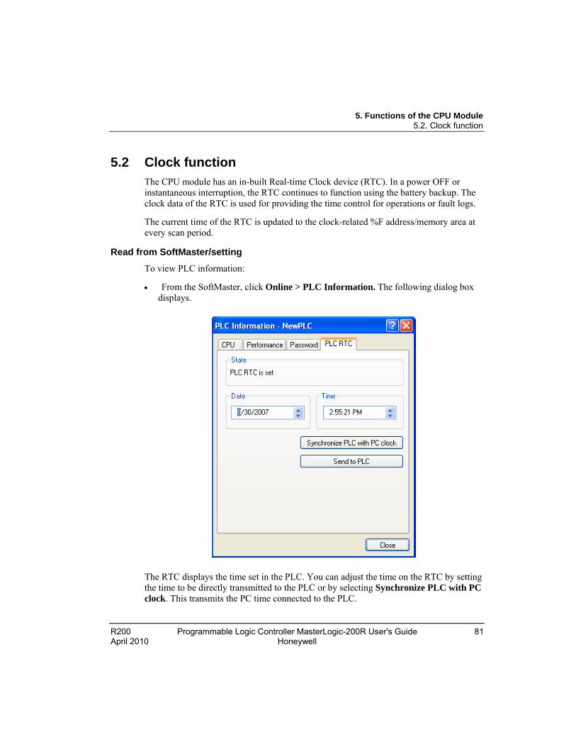
5. Functions of the CPU Module 5.2. Clock function
R200 Programmable Logic Controller MasterLogic-200R User's Guide 81 April 2010 Honeywell
5.2 Clock function The CPU module has an in-built Real-time Clock device (RTC). In a power OFF or instantaneous interruption, the RTC continues to function using the battery backup. The clock data of the RTC is used for providing the time control for operations or fault logs.
The current time of the RTC is updated to the clock-related %F address/memory area at every scan period.
Read from SoftMaster/setting
To view PLC information:
From the SoftMaster, click Online > PLC Information. The following dialog box displays.
The RTC displays the time set in the PLC. You can adjust the time on the RTC by setting the time to be directly transmitted to the PLC or by selecting Synchronize PLC with PC clock. This transmits the PC time connected to the PLC.

5. Functions of the CPU Module 5.2. Clock function
82 Programmable Logic Controller MasterLogic-200R User's Guide R200 Honeywell April 2010
Clock reading by flag
It can be monitored by flags as detailed in the following table.
Flags to Read the Clock
Example Size F Area Description
_RTC_TIME[0] 16#08 BYTE %FB12 Current Time [Year, 20XX]
_RTC_TIME[1] 16#02 BYTE %FB13 Current Time [Month]
_RTC_TIME[2] 16#23 BYTE %FB14 Current Time [Day]
_RTC_TIME[3] 16#14 BYTE %FB15 Current Time [Hour]
_RTC_TIME[4] 16#16 BYTE %FB16 Current Time [Minute]
_RTC_TIME[5] 16#17 BYTE %FB17 Current Time [Second]
_RTC_TIME[6] 16#06 BYTE %FB18 Current Time [Day of week]
_RTC_TIME[7] 16#20 BYTE %FB19 Current Time [Year, XX08]
The time data of _TIME_DAY_DT is displayed on 24 hr basis.
RTC data modification through program
You can set the RTC value using the SoftMaster program. This function is used when the time is manually set using the external digital switch or by designing a system that periodically calibrates the clock time on the network.
Set ‘DATEWR’ to ON and insert the setting value in the %F address/memory area and enter the time in RTC at scan END.
Flags to Read the Clock
Example Size F Area Description
_RTC_TIME_USER[0] 16#00 BYTE %FB3860 Time [Year, 20XX]
_RTC_TIME_USER [1] 16#00 BYTE %FB3861 Time [Month]
_RTC_TIME_USER [2] 16#00 BYTE %FB3862 Time [Day]
_RTC_TIME_USER [3] 16#00 BYTE %FB3863 Time [Hour]
_RTC_TIME_USER [4] 16#00 BYTE %FB3864 Time [Minute]
_RTC_TIME_USER [5] 16#00 BYTE %FB3865 Time [Second]

5. Functions of the CPU Module 5.2. Clock function
R200 Programmable Logic Controller MasterLogic-200R User's Guide 83 April 2010 Honeywell
Flags to Read the Clock
Example Size F Area Description
_RTC_TIME_USER [6] 16#00 BYTE %FB3866 Time [Day of week]
_RTC_TIME_USER [7] 16#00 BYTE %FB3867 Time [Year, XX08]
Enter the time data in the format prescribed in the table. Monitor the RTC read device to check if the RTC data is modified correctly.
The Weekday expression method is used for representing the weekday in a Ladder Program. For example, 3 represents a Wednesday wherever we need to specify a date as indicated in the following table.
Number 0 1 2 3 4 5 6
Day Sunday Monday Tuesday Wednesday Thursday Friday Saturday
Time tolerance
The RTC tolerance depends on the ambient temperature. Time tolerance according to temperature per day is indicated in the following table.
Operating Temperature
Maximum Error (sec/date) Ordinary (sec/date)
0°C - 4.67 ~ 1.38 -1.46
25°C - 1.64 ~ 2.42 0.43
55°C - 5.79 ~ 0.78 -2.29
5. Functions of the CPU Module 5.2. Clock function
84 Programmable Logic Controller MasterLogic-200R User's Guide R200 Honeywell April 2010
ATTENTION
Initially, the RTC may not have any clock data.
Set the clock data correctly before beginning to use the CPU module.
In case the data is out of range of the clock data written in the RTC, it may not function normally. Example: 14Month 32Day 25Hour.
RTC may stop or give an error because of battery error. If new clock data is written in the RTC, the error is cleared.
REFERENCE – INTERNAL
For additional information on modifying the clock data, refer to MasterLogic-200 Instructions User Guide.

5. Functions of the CPU Module 5.3. Remote functions
R200 Programmable Logic Controller MasterLogic-200R User's Guide 85 April 2010 Honeywell
5.3 Remote functions
Overview of remote functions
The key switch installed on the local CPU is used for operating a remote CPU, connected to it. To operate the CPU remotely, set ‘REM’ switch (second dip switch of four pin dip switch) of the CPU module ‘ON’ and move ‘RUN/STOP’ switch to ‘STOP’ position.
Types of remote operation
You can perform remote operation by:
Connecting the SoftMaster through the USB or RS-232 port available in the CPU module.
Using SoftMaster to connect to another PLC on the same network, as illustrated in the following figures.

5. Functions of the CPU Module 5.3. Remote functions
86 Programmable Logic Controller MasterLogic-200R User's Guide R200 Honeywell April 2010
Remote RUN/STOP
Remote RUN/STOP function performs RUN/STOP when the DIP switch of the CPU module is in REMOTE position and RUN/STOP switch is in STOP position.
When the CPU module is installed in an inaccessible location and is difficult to operate, it is convenient to control it using Remote RUN/STOP.
Remote DEBUG
Remote DEBUG is a function that performs DEBUG operation when DIP switch of the CPU module is in REMOTE position and RUN/STOP switch is in STOP position.
It is convenient to check the execution state of a program or the contents of each data from debugging function using REMOTE DEBUG Mode.
Remote Reset
Remote Reset function is used for resetting a CPU module by running a remote operation when an error occurs and it is not possible to operate a CPU module.
This supports ‘Reset’ and ‘Overall Reset’ like an operation by switch.
REFERENCE - INTERNAL
For more information about remote functions, refer to ‘Online’ section in the SoftMaster User’s Guide.
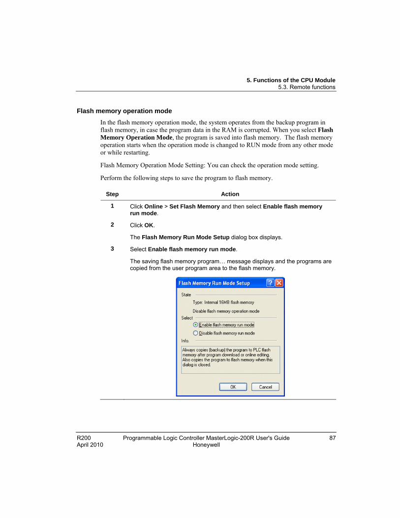
5. Functions of the CPU Module 5.3. Remote functions
R200 Programmable Logic Controller MasterLogic-200R User's Guide 87 April 2010 Honeywell
Flash memory operation mode
In the flash memory operation mode, the system operates from the backup program in flash memory, in case the program data in the RAM is corrupted. When you select Flash Memory Operation Mode, the program is saved into flash memory. The flash memory operation starts when the operation mode is changed to RUN mode from any other mode or while restarting.
Flash Memory Operation Mode Setting: You can check the operation mode setting.
Perform the following steps to save the program to flash memory.
Step Action
1 Click Online > Set Flash Memory and then select Enable flash memory run mode.
2 Click OK.
The Flash Memory Run Mode Setup dialog box displays.
3 Select Enable flash memory run mode.
The saving flash memory program… message displays and the programs are copied from the user program area to the flash memory.

5. Functions of the CPU Module 5.3. Remote functions
88 Programmable Logic Controller MasterLogic-200R User's Guide R200 Honeywell April 2010
Step Action
ATTENTION
The default option is Flash Memory Operation Mode not selected.
Flash Memory Operation Mode can be changed, irrespective of RUN/STOP mode.
Flash Memory Operation Mode can be set from the online menu in SoftMaster. This is done, while executing flash ‘operation mode setting’, after program debugging is complete with the flash memory operation mode OFF.
If the flash memory operation setting is modified to flash memory operation mode during RUN and the program is successfully written in the flash memory, the changed program will be applied only when it restarts. Note that if the PLC restarts before a program is saved into flash memory; the previous program that was saved earlier operates, instead of the changed program.
If flash memory operation mode is changed from ‘disable’ to ‘enable’, the flash memory operation mode is applied until the flash memory writing is complete. In case the PLC restarts before completing program writing, ’Flash memory operation mode’ is released.
5. Functions of the CPU Module 5.3. Remote functions
R200 Programmable Logic Controller MasterLogic-200R User's Guide 89 April 2010 Honeywell
Flash memory operation method
Depending on the flash memory operation mode setting, the PLC operates as indicated in the following table when the PLC is restarted or its operating mode is ON.
Flash Memory Operation Mode Setting
Description
ON
If program memory data is corrupted because flash memory and program memory are different or battery voltage is low, it downloads the program saved in the flash memory to the program memory.
OFF CPU detects that the flash memory does not have any program and operates by the program saved in the RAM.

5. Functions of the CPU Module 5.4. Forced ON/OFF of I/O
90 Programmable Logic Controller MasterLogic-200R User's Guide R200 Honeywell April 2010
5.4 Forced ON/OFF of I/O
Forced I/O setting
The forced I/O setting function is used for forcibly turning ON or OFF I/O channels, irrespective of the program execution results.
Perform the following steps to turn ON or OFF I/O channels.
Step Action
1 Click Online > Force I/O.
2
3 Select appropriate flag, and then select appropriate data check box of P device to set Forced I/O.
4 To set the value ‘1’, select corresponding bit data and flag.
5. Functions of the CPU Module 5.4. Forced ON/OFF of I/O
R200 Programmable Logic Controller MasterLogic-200R User's Guide 91 April 2010 Honeywell
Step Action
5 To set the value ’0’, select only the flag.
The setting is applied when forced input or output is enabled.
ATTENTION
Forced I/O setting is applicable only on DI/DO modules. It is not applicable to special modules.
Forced I/O setting is available only in local I/O modules. When forced I/O is set, ’CHK LED’ is ON.
The forced I/O setting is maintained, even after a new program is downloaded.
WARNING
Forcing can energize the I/O and may cause serious malfunction in the process or threat to human life.
REFERENCE - INTERNAL
For more information on Forced I/O setting, refer to SoftMaster User’s Guide.
Forced On/Off processing time and processing method
Forced input
The input forces the data of the contact point (Digital Input) selected and sets as forced ON/OFF. At the time of input refresh the forced data is updated to the input image area. Therefore, the user program operates with actual input data while the forced setting area operates with forced setting data.
Forced output
The output replaces data of contact point (Digital Output) selected and sets as forced ON/OFF from the data of output image area. This is achieved during output refresh, on completion of the user program operation execution with the forced setting data. It makes changes in the output module. In case of output, the data of output image area does not change by forced ON/OFF setting.

5. Functions of the CPU Module 5.4. Forced ON/OFF of I/O
92 Programmable Logic Controller MasterLogic-200R User's Guide R200 Honeywell April 2010
Cautions for using forced I/O
For forcing the point, the Force Flag needs to be set.
It is possible to set the forced input even if the actual I/O module is not installed.
The data set in the CPU is retained till it is cleared.
Forced I/O data is not cleared even if CPU is in Stop mode.
Click Delete all to clear all settings and set forced value again.
Direct I/O operation
The ‘DIREC_IN, DIREC_OUT’ function is used to change the I/O values. This enables you to read the state of input and output contact points directly during program execution.
ATTENTION
When DIREC_IN,DIREC_OUT’ function is used, the value is applied immediately, and it precedes Forced I/O.
REFERENCE - INTERNAL
For more information about the DIREC_IN,DIREC_OUT’ function, refer to SoftMaster Instruction Guide.

5. Functions of the CPU Module 5.5. Viewing PLC error/event log
R200 Programmable Logic Controller MasterLogic-200R User's Guide 93 April 2010 Honeywell
5.5 Viewing PLC error/event log
Overview of operation history
The four types of logs are as follows:
Error log
Mode change log
Shut down log
System log
The PLC saves the time, frequency, and operation of each event in memory. This can be monitored from SoftMaster. The operation log is continuously saved in the PLC unless it is deleted using SoftMaster.
Error log
The PLC saves the errors that occur during operation into an error log. It saves the following details of errors:
Error code, date, time, and error details.
Error history of the errors that occur during operation.
It saves a maximum of 2048 messages. The error history is automatically stored in case memory backup fails due to low battery.
Mode change log
In the event of a change in operation mode, the PLC saves this information with a time-stamp.
It saves the date, time, and mode change information.
It saves up to 1024 mode change events.
Power shut down log
The PLC saves power ON/OFF data, with its time stamp. It saves On/Off information, date and time. It saves a maximum of 1024 power ON/OFF events.
System log
The PLC saves operation history of the system during operation.
It saves the date, time, and operation changes.
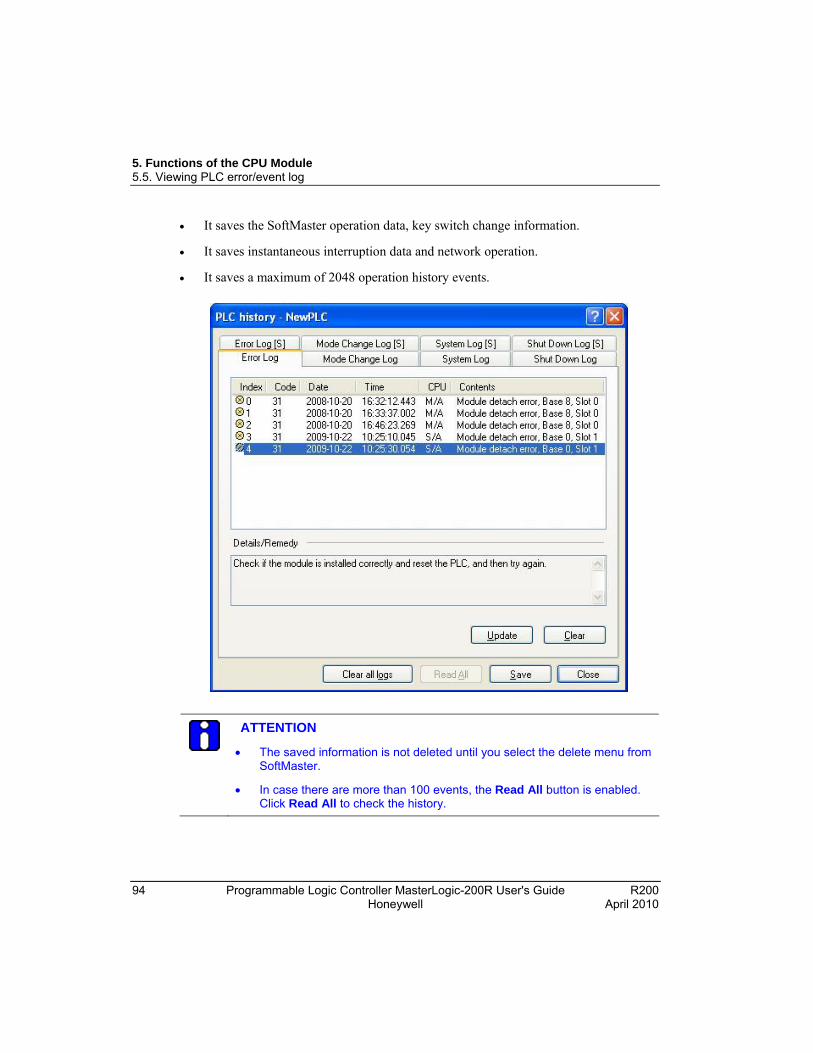
5. Functions of the CPU Module 5.5. Viewing PLC error/event log
94 Programmable Logic Controller MasterLogic-200R User's Guide R200 Honeywell April 2010
It saves the SoftMaster operation data, key switch change information.
It saves instantaneous interruption data and network operation.
It saves a maximum of 2048 operation history events.
ATTENTION
The saved information is not deleted until you select the delete menu from SoftMaster.
In case there are more than 100 events, the Read All button is enabled. Click Read All to check the history.
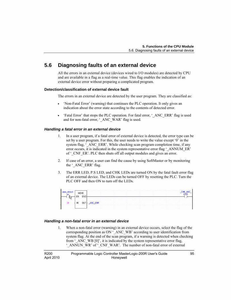
5. Functions of the CPU Module 5.6. Diagnosing faults of an external device
R200 Programmable Logic Controller MasterLogic-200R User's Guide 95 April 2010 Honeywell
5.6 Diagnosing faults of an external device All the errors in an external device (devices wired to I/O modules) are detected by CPU and are available in a flag as a real-time value. This flag enables the indication of an external device error without preparing a complicated program.
Detection/classification of external device fault
The errors in an external device are detected by the user program. They are classified as:
‘Non-Fatal Error’ (warning) that continues the PLC operation. It only gives an indication about the error state according to the contents of detected error.
‘Fatal Error’ that stops the PLC operation. For fatal error, ‘_ANC_ERR’ flag is used and for non-fatal error, ‘_ANC_WAR’ flag is used.
Handling a fatal error in an external device
1. In a user program, if a fatal error of external device is detected, the error type can be set by a user program. For this, the user needs to write the value except ‘0’ in the system flag, ‘_ANC_ERR’. While checking scan program completion time, if any error occurs, it is indicated in the system representative error flag ‘_ANNUM_ER’ of ‘_CNF_ER’. PLC then shuts off all output modules and gives an error.
2. If case of an error, a user can find the cause by using SoftMaster or by monitoring the ‘_ANC_ERR’ flag.
3. The ERR LED, P.S LED, and CHK LEDs are turned ON by the fatal fault error flag of an external device. The LEDs can be turned OFF by resetting the PLC. Turn the PLC OFF and then ON to turn off the LEDs.
Handling a non-fatal error in an external device
1. When a non-fatal error (warning) in an external device occurs, select the flag of the corresponding position as ON ‘_ANC_WB’ according to user identification from system flag. At the end of the scan program, if a warning is detected when checking from ‘_ANC_WB [0]’, it is indicated by the system representative error flag, ‘_ANNUN_WR’ of ‘_CNF_WAR’. The number of non-fatal error of external
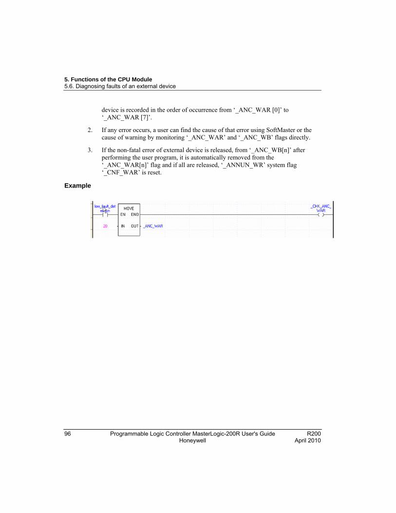
5. Functions of the CPU Module 5.6. Diagnosing faults of an external device
96 Programmable Logic Controller MasterLogic-200R User's Guide R200 Honeywell April 2010
device is recorded in the order of occurrence from ‘_ANC_WAR [0]’ to ‘_ANC_WAR [7]’.
2. If any error occurs, a user can find the cause of that error using SoftMaster or the cause of warning by monitoring ‘_ANC_WAR’ and ‘_ANC_WB’ flags directly.
3. If the non-fatal error of external device is released, from ‘_ANC_WB[n]’ after performing the user program, it is automatically removed from the ‘_ANC_WAR[n]’ flag and if all are released, ‘_ANNUN_WR’ system flag ‘_CNF_WAR’ is reset.
Example
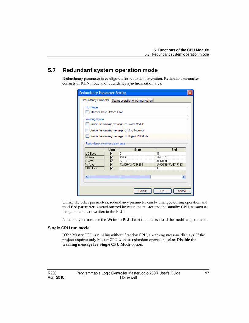
5. Functions of the CPU Module 5.7. Redundant system operation mode
R200 Programmable Logic Controller MasterLogic-200R User's Guide 97 April 2010 Honeywell
5.7 Redundant system operation mode Redundancy parameter is configured for redundant operation. Redundant parameter consists of RUN mode and redundancy synchronization area.
Unlike the other parameters, redundancy parameter can be changed during operation and modified parameter is synchronized between the master and the standby CPU, as soon as the parameters are written to the PLC.
Note that you must use the Write to PLC function, to download the modified parameter.
Single CPU run mode
If the Master CPU is running without Standby CPU, a warning message displays. If the project requires only Master CPU without redundant operation, select Disable the warning message for Single CPU Mode option.

5. Functions of the CPU Module 5.7. Redundant system operation mode
98 Programmable Logic Controller MasterLogic-200R User's Guide R200 Honeywell April 2010
ATTENTION
It is recommended to configure redundancy for MasterLogic-200R. In case of Single CPU run mode, the system fails, if there is an error in the CPU.
Extended base detach error
This section defines procedure to handle the situation if the extension base is detached (or power off).
a) Clear the Extended Base Detach Error check box. This is a default setting. If there is an error in one of the extension bases, the system restarts and the CPU waits until the base in failure is normalized. The base failure is indicated with ‘Ebxx’ in the CPU indicator panel.
b) Select the Extended Base Detach Error check box. If there is an error in one of the extension bases, other bases operate as per error settings defined in the basic parameter.

5. Functions of the CPU Module 5.7. Redundant system operation mode
R200 Programmable Logic Controller MasterLogic-200R User's Guide 99 April 2010 Honeywell
If it is set to Keep output when an error occurs in the basic parameters, the output of other bases keep the last output.
Redundancy synchronization area
M Area : %MW0 ~ %MW131071 (default setting is %MW0 ~ %MW2000)
I/Q Base: 0 ~ 31
PID Block: 0 ~ 7
R(W) Area: %RW0 ~ %RW32767 (default setting is %RW0 ~ %RW2000)
ATTENTION
1. Retain area for %M can be defined in basic parameters. Refer to Redundant system operation.
2. If Master/Standby CPU continues with redundant operation, the following area is synchronized automatically. - L (High-Speed Link flag) and N (P2P parameter) area. - F (System flag): However, individual flag area is not synchronized - U (Special flag)
3. If you change the value in the variable monitoring window, the value is applied to both Master and Standby CPU, regardless of synchronization area.
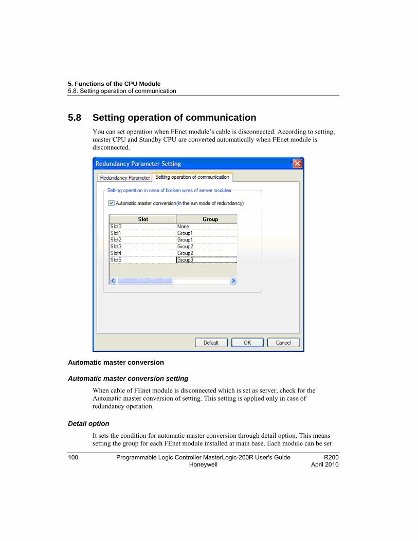
5. Functions of the CPU Module 5.8. Setting operation of communication
100 Programmable Logic Controller MasterLogic-200R User's Guide R200 Honeywell April 2010
5.8 Setting operation of communication You can set operation when FEnet module’s cable is disconnected. According to setting, master CPU and Standby CPU are converted automatically when FEnet module is disconnected.
Automatic master conversion
Automatic master conversion setting
When cable of FEnet module is disconnected which is set as server, check for the Automatic master conversion of setting. This setting is applied only in case of redundancy operation.
Detail option
It sets the condition for automatic master conversion through detail option. This means setting the group for each FEnet module installed at main base. Each module can be set
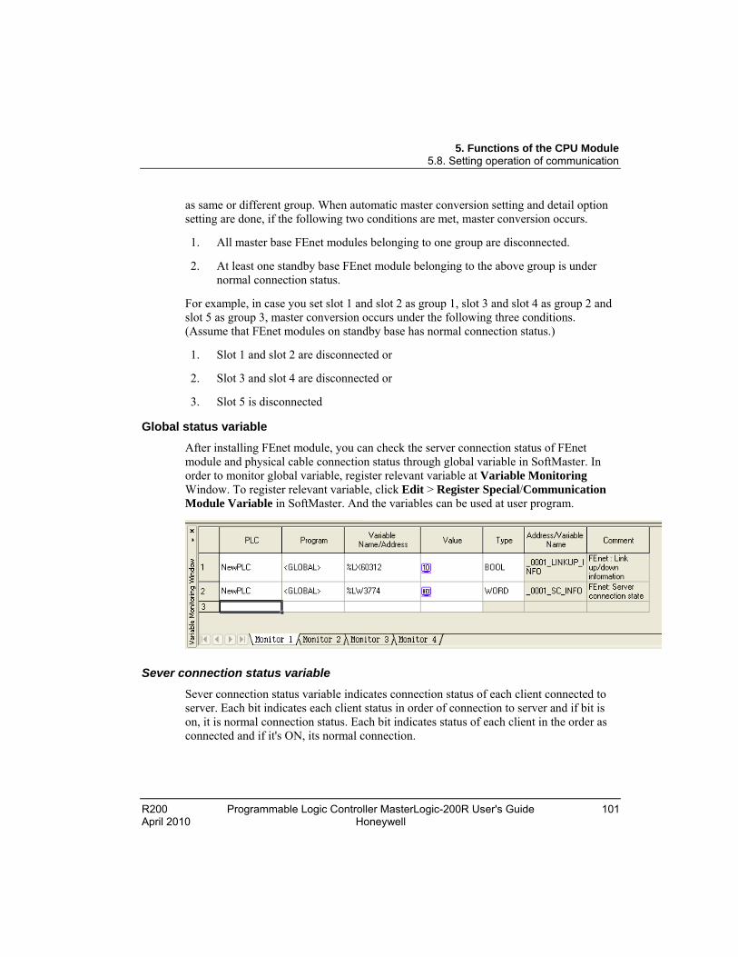
5. Functions of the CPU Module 5.8. Setting operation of communication
R200 Programmable Logic Controller MasterLogic-200R User's Guide 101 April 2010 Honeywell
as same or different group. When automatic master conversion setting and detail option setting are done, if the following two conditions are met, master conversion occurs.
1. All master base FEnet modules belonging to one group are disconnected.
2. At least one standby base FEnet module belonging to the above group is under normal connection status.
For example, in case you set slot 1 and slot 2 as group 1, slot 3 and slot 4 as group 2 and slot 5 as group 3, master conversion occurs under the following three conditions. (Assume that FEnet modules on standby base has normal connection status.)
1. Slot 1 and slot 2 are disconnected or
2. Slot 3 and slot 4 are disconnected or
3. Slot 5 is disconnected
Global status variable
After installing FEnet module, you can check the server connection status of FEnet module and physical cable connection status through global variable in SoftMaster. In order to monitor global variable, register relevant variable at Variable Monitoring Window. To register relevant variable, click Edit > Register Special/Communication Module Variable in SoftMaster. And the variables can be used at user program.
Sever connection status variable
Sever connection status variable indicates connection status of each client connected to server. Each bit indicates each client status in order of connection to server and if bit is on, it is normal connection status. Each bit indicates status of each client in the order as connected and if it's ON, its normal connection.
5. Functions of the CPU Module 5.8. Setting operation of communication
102 Programmable Logic Controller MasterLogic-200R User's Guide R200 Honeywell April 2010
Link up/down information variable
Link up/down information variable indicates physical cable connection status of relevant FEnet module. If variable is on, it means normal connection and if variable is off, it means disconnection or detachment.
ONE IP solution
You can connect to the master base FEnet module of 2MLR redundancy system with one IP regardless of master conversion through ONE IP Solution. For this, in case of master conversion, master base FEnet module and standby FEnet module change each other’s IP address.
IP setting
You can set IP of FEnet module at standard setting window after registering FEnet module at SoftMaster-NM. If you check ONE IP Solution of standard setting window, ONE IP Solution function will be activated and you can set only one IP address for FEnet in a slot.
REFERENCE - INTERNAL
Refer FENet user’s guide for how to set IP address when ONE IP Solution is not activated.
When using ONE IP Solution, IP address should be an even number. This IP address becomes IP address of master base FEnet module and master base FEnet module’s IP address + 1, becomes IP address of standby base FEnet module.
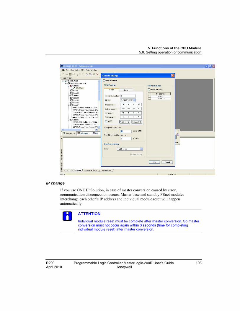
5. Functions of the CPU Module 5.8. Setting operation of communication
R200 Programmable Logic Controller MasterLogic-200R User's Guide 103 April 2010 Honeywell
IP change
If you use ONE IP Solution, in case of master conversion caused by error, communication disconnection occurs. Master base and standby FEnet modules interchange each other’s IP address and individual module reset will happen automatically.
ATTENTION
Individual module reset must be complete after master conversion. So master conversion must not occur again within 3 seconds (time for completing individual module reset) after master conversion.

5. Functions of the CPU Module 5.9. Fault mask function
104 Programmable Logic Controller MasterLogic-200R User's Guide R200 Honeywell April 2010
5.9 Fault mask function
Fault mask operational overview
The fault mask enables uninterrupted program execution, even in case of errors in the module.
If the error occurs in the module where the fault mask is set, the corresponding module stops operation. However, the rest of the system continues to operate.
If the module error occurs when the PLC is in RUN mode, the CPU module sets the error flag and the front PS LED’ turns ON. You can see the error state through SoftMaster.
Setting fault mask
The fault mask can be set from the online menu in SoftMaster. Fault mask can be also set by a program. It is achieved by setting fault mask flag with a program.
REFERENCE - INTERNAL
For additional information on fault mask setting, refer to SoftMaster User’s Guide.
For additional information on setting fault mask through a program, refer to Flag list .
Releasing fault mask
The fault mask can be released in the following ways.
Setting release from online menu in SoftMaster.
Release by program.
Automatic release in case memory backup is lost because of battery voltage falling.
Reset Key when it is pressed for more than 3 seconds.
5. Functions of the CPU Module 5.9. Fault mask function
R200 Programmable Logic Controller MasterLogic-200R User's Guide 105 April 2010 Honeywell
The fault mask is not released in the following cases.
Power Off→On
Operation mode change
Program download
Reset key
Data clear
ATTENTION
Check the state of the error flag before releasing the fault mask flag. The system goes to STOP mode, if the fault mask is released without clearing the error flag.
5. Functions of the CPU Module 5.10. I/O module skip function
106 Programmable Logic Controller MasterLogic-200R User's Guide R200 Honeywell April 2010
5.10 I/O module skip function
I/O module skip operational overview
The I/O module skip function is used for excluding a designated module from operation, while the PLC is in RUN Mode. The I/O data updation and error diagnosis ceases for the designated module. It is used for operating it temporarily, excluding the fault.
Setting and processing I/O data
The SoftMaster is used for configuring the skip setting on the I/O module.
REFERENCE – INTERNAL
For additional information about skip setting, refer to SoftMaster User’s Guide.
Input (I) image area suspends input refresh, and maintains the value set before the skip setting. At this time, it is possible to operate the image by forced ON/OFF.
The actual output of the output module is set to OFF, when setting the skip function. But output image changes depending on a user program’s operation, irrespective of the skip setting. After the skip setting, the output value of the output module cannot be controlled by forced ON/OFF.
The skip function is executed similarly as described above, even while using I/O function.
Releasing skip function
The I/O module skip function is released by the following methods.
Using the online menu in SoftMaster
Releasing by overall reset
Automatically released, in case of memory backup failure because of low-battery level.
Reset Key when it is pressed for more than 3 seconds.

5. Functions of the CPU Module 5.10. I/O module skip function
R200 Programmable Logic Controller MasterLogic-200R User's Guide 107 April 2010 Honeywell
Note that the fault mask is not released in the following cases.
Power Off→On
Operation mode change
Program download
Reset key
Data clear
ATTENTION
If a fault is found in a module when releasing the skip function, the system may stop. Before releasing the skip function, ensure the release of the skip with fault mask set and check the operation of the module.
5. Functions of the CPU Module 5.11. Replacing a module during operation
108 Programmable Logic Controller MasterLogic-200R User's Guide R200 Honeywell April 2010
5.11 Replacing a module during operation
Overview of replacing modules
The MasterLogic-200R system enables you to change the modules while the PLC is in RUN mode. However, special care must be taken while changing the modules, as it can lead to abnormalities in the system.
CAUTION
Replaceable modules during operation are digital I/O, analog I/O, RTD, and TC modules. HSC and APM modules can be replaced but does not retain the previous values.
Communication module 2MLL-PMEA can be connected as long as the network is set (using Sycon software).
While replacing a module, align the bottom of the base and the holding part of a module before inserting it. Incorrect installation may cause the system to shutdown.
Replacing modules
Replaceable modules during operation are digital I/O, analog I/O, RTD, TC, and Base modules. This guide only provides a guideline to replace modules by changing wizard in SoftMaster
Using the module changing wizard in SoftMaster
REFERENCE – INTERNAL
For additional information, refer to SoftMaster User’s Guide.
Using the base changing wizard in SoftMaster
Extension base can be replaced during online. In line configuration, only the last extension base in the line can be replaced. However, in the ring configuration, any extension base part of ring topology can be replaced during operation.
REFERENCE – INTERNAL
For additional information, refer to SoftMaster User’s Guide.

5. Functions of the CPU Module 5.11. Replacing a module during operation
R200 Programmable Logic Controller MasterLogic-200R User's Guide 109 April 2010 Honeywell
CAUTION
You can replace only one extension base at a time.
Main base cannot be replaced during operation.
Allocating I/O address
I/O address allocation refers to assigning the address to the I/O terminal of each module. This enables reading data from an input module and transmitting the data to an output module.
The I/O number allocation is related with the base number, slot position, and module type. The number is allocated by the fixed method in the 2MLR-CPUH.
Program modification during operation
During the PLC operation, a program and some parameters can be modified without interruption to the control.
REFERENCE – INTERNAL
For additional information on Program modification during operation, refer to SoftMaster User’s Guide.
The items modifiable during operations are as follows:
Program
Communication parameters
ATTENTION
The basic parameters and I/O parameters cannot be modified during operation. To modify these parameters, it is necessary to stop operation.

5. Functions of the CPU Module 5.11. Replacing a module during operation
110 Programmable Logic Controller MasterLogic-200R User's Guide R200 Honeywell April 2010

R200 Programmable Logic Controller MasterLogic-200R User's Guide 111 April 2010 Honeywell
6. Configuration
6.1 System configuration
Redundancy components list
MasterLogic-200R system consists of the following redundant components.
Item Type Description
2MLR-CPUH/F
Maximum I/O points: 23808, Program capacity: 1MB
Fiber Optic Redundant CPU module
2MLR-CPUH/T
Maximum I/O points: 23808, Program capacity: 1MB
RJ45
Redundant Main Base
2MLR-M06P Main base for Redundant CPU, Power Supply
6 communication modules
Redundant Extension Base
2MLR-E12P Extension base for I/O modules
12 I/O modules
2MLR-DBST Communication module for 2MLR extension base operation. Electrical media
2MLR-DBSF Communication module for 2MLR extension base operation. Optical media
Extension Drive Module
2MLR-DBSH Communication module for 2MLR extension base operation. Electrical/optical media mixing
2MLR-AC12 DC5V: 5.5A, AC110V
2MLR-AC22 DC5V: 5.5A, AC220V
2MLR-AC13 DC5V: 8.5A, AC110V
2MLR-AC23 DC5V: 8.5A, AC220V
Redundant Power Supply
2MLR-DC42 DC5V: 7.5A, DC24V
Sync Cable 2MLC-F201 LC type optical cable (Multi core), length:2m

6. Configuration 6.1. System configuration
112 Programmable Logic Controller MasterLogic-200R User's Guide R200 Honeywell April 2010
Item Type Description
2MLC-F301 LC type optical cable (Multi core), length:3m
2MLC-F501 LC type optical cable (Multi core), length:5m
2MLC-C001 Twisted pair cable
FTP used
2MLC-F201 LC type optical cable (Multi core), length:2m
2MLC-F301 LC type optical cable (Multi core), length:3m
I/O Extension Cable
2MLC-F501 LC type optical cable (Multi core), length:5m
Dustproof module 2MLR-DMMA Dustproof module for not used power module slot
Common components list for MasterLogic-200
Item Type Description
2MLI-D21A DC 24V input, 8 points (current source/sink input)
2MLI-D22A DC 24V input, 16 points (current source/sink input)
2MLI-D24A DC 24V input, 32 points (current source/sink input)
2MLI-D28A DC 24V input, 64 points (current source/sink input)
2MLI-D22B DC 24V input, 16 points (current source input)
2MLI-D24B DC 24V input, 32 points (current source input)
2MLI-D28B DC 24V input, 64 points (current source input)
2MLI-A12A AC 110V input, 16 points
Digital input module
2MLI-A21A AC 220V input, 8 points
2MLQ-RY1A Relay output, 8 points (2A, independent COM)
2MLQ-RY2A Relay output, 16 points (2A)
Digital output module
2MLQ-RY2B Relay output, 16 points (2A), built-in varistor
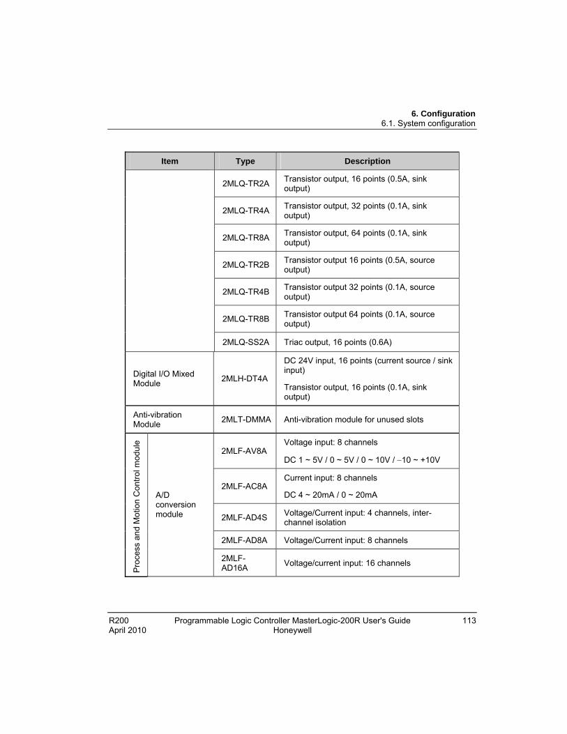
6. Configuration 6.1. System configuration
R200 Programmable Logic Controller MasterLogic-200R User's Guide 113 April 2010 Honeywell
Item Type Description
2MLQ-TR2A Transistor output, 16 points (0.5A, sink output)
2MLQ-TR4A Transistor output, 32 points (0.1A, sink output)
2MLQ-TR8A Transistor output, 64 points (0.1A, sink output)
2MLQ-TR2B Transistor output 16 points (0.5A, source output)
2MLQ-TR4B Transistor output 32 points (0.1A, source output)
2MLQ-TR8B Transistor output 64 points (0.1A, source output)
2MLQ-SS2A Triac output, 16 points (0.6A)
Digital I/O Mixed Module
2MLH-DT4A
DC 24V input, 16 points (current source / sink input)
Transistor output, 16 points (0.1A, sink output)
Anti-vibration Module
2MLT-DMMA Anti-vibration module for unused slots
2MLF-AV8A Voltage input: 8 channels
DC 1 ~ 5V / 0 ~ 5V / 0 ~ 10V / 10 ~ +10V
2MLF-AC8A Current input: 8 channels
DC 4 ~ 20mA / 0 ~ 20mA
2MLF-AD4S Voltage/Current input: 4 channels, inter-channel isolation
2MLF-AD8A Voltage/Current input: 8 channels
Pro
cess
an
d M
otio
n C
ontr
ol m
odul
e
A/D conversion module
2MLF-AD16A
Voltage/current input: 16 channels

6. Configuration 6.1. System configuration
114 Programmable Logic Controller MasterLogic-200R User's Guide R200 Honeywell April 2010
Item Type Description
2MLF-DV4A Voltage output: 4 channels
DC 1 ~ 5V / 0 ~ 5V / 0 ~ 10V / 10 ~ +10V
2MLF-DC4A Current output: 4 channels
DC 4 ~ 20mA / 0 ~ 20mA
2MLF-DV4S Voltage output: 4 channels, insulated channel
2MLF-DC4S Current output: 4 channels, inter-channel isolation
2MLF-DV8A Voltage output: 8 channels
DC 1 ~ 5V / 0 ~ 5V / 0 ~ 10V / 10 ~ +10V
D/A conversion module
2MLF-DC8A Current output: 8 channels
DC 4 ~ 20mA / 0 ~ 20mA
Thermocouple input module
2MLF-TC4S Temperature (T/C) input, 4 channels, inter-channel isolation
2MLF-RD4A Temperature (RTD) input 4 channels Resistance temperature detector input module
2MLF-RD4S Temperature (RTD) input, 4 channels (inter-channel isolation type)
2MLF-HO2A Voltage input type (Open Collector type) 200kpps, 2 channels High-Speed
Counter module 2MLF-HD2A
Differential input (Line Driver type)
500kpps, 2 channels
2MLF-PO3A Pulse output (Open Collector type), 3 axes
2MLF-PO2A Pulse output (Open Collector type), 2 axes
2MLF-PO1A Pulse output (Open Collector type), 1 axis
APM module
(Advanced Position module )
2MLF-PD3A Pulse output (Line Driver type), 3 axes

6. Configuration 6.1. System configuration
R200 Programmable Logic Controller MasterLogic-200R User's Guide 115 April 2010 Honeywell
Item Type Description
2MLF-PD2A Pulse output (Line Driver type), 2 axes
2MLF-PD1A Pulse output (Line Driver type), 1 axis
Motion control module
2MLF-M16M Motion-dedicated net (Mechatrolink-II) type, 16 axes
2MLL-EFMF
Fast Ethernet (optical), Master
100/10 Mbps supported
‘Optical’ does not support 10Mbps
2MLL-EFMT
Fast Ethernet (electrical), Master
100/10 Mbps supported
FEnet I/F module
(Optical/Electric)
2MLL-ESHF Optical switch module for fast Ethernet
2MLL-C22A
Serial communication
RS-232C, 2 channels
2MLL-C42A
Serial communication
RS-422(485), 2 channels
Com
mun
icat
ion
Mod
ule Snet I/F
module
2MLL-CH2A
Serial communication
RS-232C 1 ch/RS-422(485) 1 ch
Profibus-DP I/F module
2MLL-PMEA Profibus-DP Master module

6. Configuration 6.1. System configuration
116 Programmable Logic Controller MasterLogic-200R User's Guide R200 Honeywell April 2010
Item Type Description
Ethernet/IP I/F Module
2MLL-EIPT EtherNet/IP (electricity)
100/10Mbps supported
Dustproof module
2MLT-DMMA Dustproof module for not used slot
ATTENTION
For further information on the above modules, refer to the respective user’s guide.

6. Configuration 6.2. Redundant configuration
R200 Programmable Logic Controller MasterLogic-200R User's Guide 117 April 2010 Honeywell
6.2 Redundant configuration
Configuring the redundant system
The basic system consisting of the main base and the extension base has the following features.
Item 2MLR-CPUH
Main Base 2 main base with same module configuration
Maximum Extension Base
31 Extension bases
Maximum I/O point
16 points module : 5952 points
32 points module : 11904 points
64 points module : 23808 points
Maximum distance between nodes
Fiber Optic : 2km
Twisted pair cable : 100m
Allocation of I/O Address in Extension base
Start address of input and output point is determined by the station number set in the extension drive module.
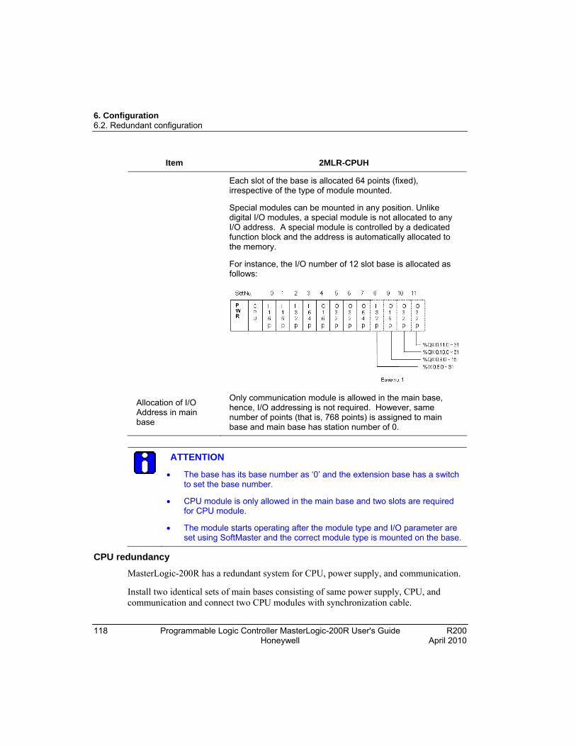
6. Configuration 6.2. Redundant configuration
118 Programmable Logic Controller MasterLogic-200R User's Guide R200 Honeywell April 2010
Item 2MLR-CPUH
Each slot of the base is allocated 64 points (fixed), irrespective of the type of module mounted.
Special modules can be mounted in any position. Unlike digital I/O modules, a special module is not allocated to any I/O address. A special module is controlled by a dedicated function block and the address is automatically allocated to the memory.
For instance, the I/O number of 12 slot base is allocated as follows:
Allocation of I/O Address in main base
Only communication module is allowed in the main base, hence, I/O addressing is not required. However, same number of points (that is, 768 points) is assigned to main base and main base has station number of 0.
ATTENTION
The base has its base number as ‘0’ and the extension base has a switch to set the base number.
CPU module is only allowed in the main base and two slots are required for CPU module.
The module starts operating after the module type and I/O parameter are set using SoftMaster and the correct module type is mounted on the base.
CPU redundancy
MasterLogic-200R has a redundant system for CPU, power supply, and communication.
Install two identical sets of main bases consisting of same power supply, CPU, and communication and connect two CPU modules with synchronization cable.
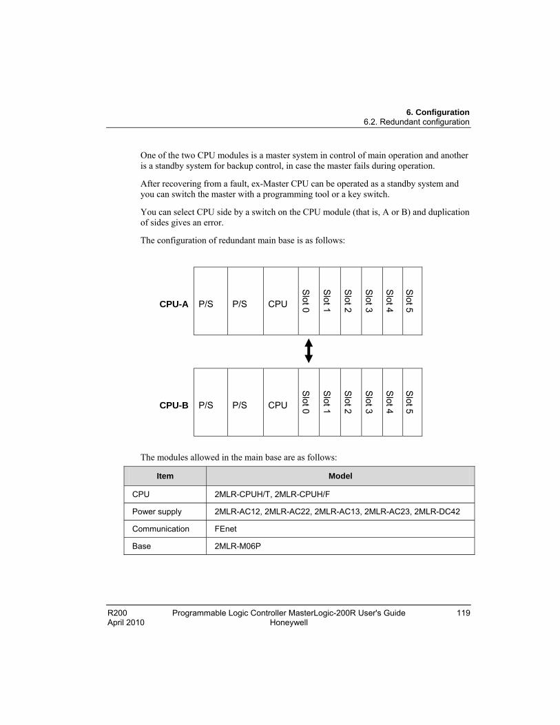
6. Configuration 6.2. Redundant configuration
R200 Programmable Logic Controller MasterLogic-200R User's Guide 119 April 2010 Honeywell
One of the two CPU modules is a master system in control of main operation and another is a standby system for backup control, in case the master fails during operation.
After recovering from a fault, ex-Master CPU can be operated as a standby system and you can switch the master with a programming tool or a key switch.
You can select CPU side by a switch on the CPU module (that is, A or B) and duplication of sides gives an error.
The configuration of redundant main base is as follows:
CPU-A P/S P/S CPU
Slot 0
Slot 1
Slot 2
Slot 3
Slot 4
Slot 5
CPU-B P/S P/S CPU
Slot 0
Slot 1
Slot 2
Slot 3
Slot 4
Slot 5
The modules allowed in the main base are as follows:
Item Model
CPU 2MLR-CPUH/T, 2MLR-CPUH/F
Power supply 2MLR-AC12, 2MLR-AC22, 2MLR-AC13, 2MLR-AC23, 2MLR-DC42
Communication FEnet
Base 2MLR-M06P
6. Configuration 6.2. Redundant configuration
120 Programmable Logic Controller MasterLogic-200R User's Guide R200 Honeywell April 2010
ATTENTION
CPU module cannot be installed in the extension base.
Both CPU modules must have the same O/S version.
The configuration of both CPU modules must be in the same sequence. Example: If 2MLL-EFMT is installed in the slot 0 of CPU-A, 2MLL-EFMT in the CPU-B must be installed in the slot 0.
Power supply redundancy
Redundant power supply can be installed in both main and extension bases. When one of the power supplies fails to operate, the system can seamlessly operate with another power supply. Faulty power supply module can be repaired during operation.
I/O bus redundancy
Extension bases and cables can be configured as a ring topology so that single communication cable fault does not stop the system and operate with another cable attached.
In a normal ring configuration, the communication is enabled to the path nearest to Master CPU.
The system continues to operate in a line configuration when there is a single fault in communication cable.

6. Configuration 6.2. Redundant configuration
R200 Programmable Logic Controller MasterLogic-200R User's Guide 121 April 2010 Honeywell
RUN mode in Ring Topology
RUN mode in Line Topology
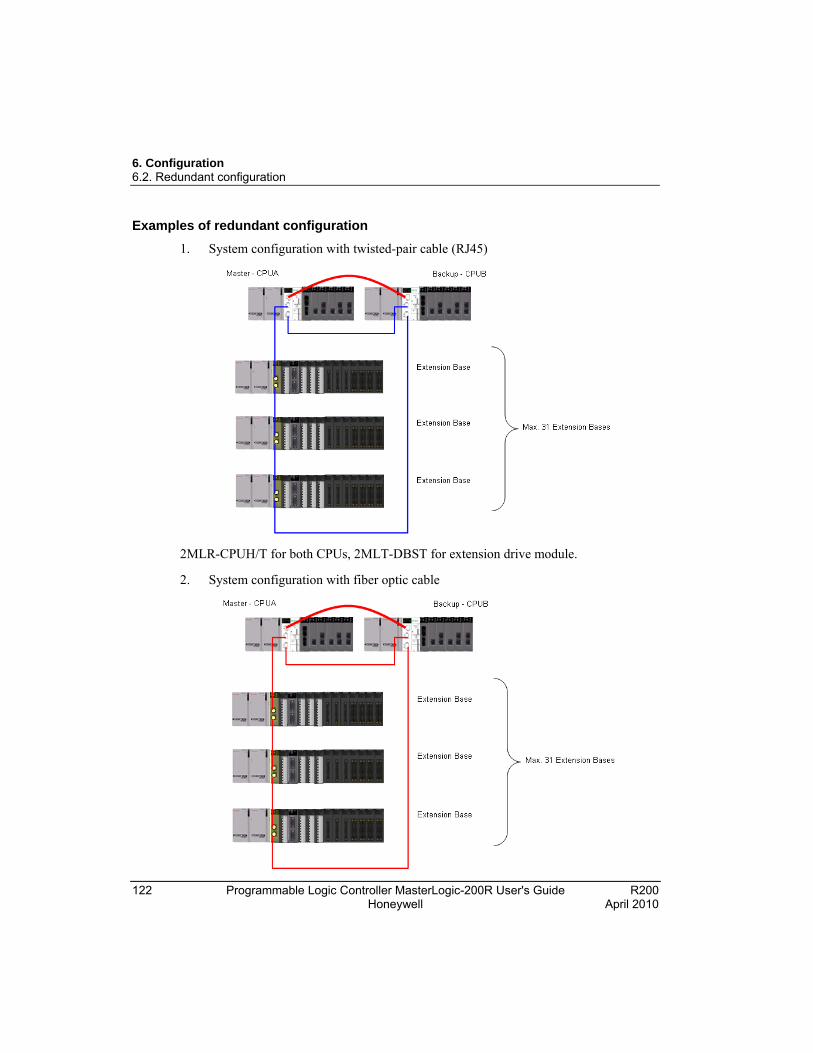
6. Configuration 6.2. Redundant configuration
122 Programmable Logic Controller MasterLogic-200R User's Guide R200 Honeywell April 2010
Examples of redundant configuration
1. System configuration with twisted-pair cable (RJ45)
2MLR-CPUH/T for both CPUs, 2MLT-DBST for extension drive module.
2. System configuration with fiber optic cable

6. Configuration 6.2. Redundant configuration
R200 Programmable Logic Controller MasterLogic-200R User's Guide 123 April 2010 Honeywell
*2MLR-CPUH/F for both CPUs, 2MLT-DBSF for extension drive module.
3. System configuration with fiber optic cable
* 2MLR-CPUH/T for both CPUs, 2MLR-DBST for extension base 1 and 2, and 2MLR-DBSH for extension base 3 and 4.
6. Configuration 6.3. Network system
124 Programmable Logic Controller MasterLogic-200R User's Guide R200 Honeywell April 2010
6.3 Network system
Inter-system network
MasterLogic-200 series supports various open networks through several communication modules for easy system configuration.
High-speed Ethernet (FEnet) module for communication with Experion PKS or other HMI systems in both TP-CAT5 and multi-mode fiber-optic media. This module can be used for peer-to-peer communication between MasterLogic-200 PLCs.
High-speed dedicated Ethernet (FDEnet) module for high performance peer-to-peer communication between MasterLogic-200 PLCs on both TP-CAT5 and fibre-optic media.
Serial communication (Snet) module for communication between PLC and serial devices, for example, RS232, RS422/485 on proprietary or open MODBUS protocols.
Profibus-DP master module (Pnet) for communication with Profibus-DP devices.
Local network
A maximum of 24 communication modules can be installed on a MasterLogic-200 PLC. They can be installed on a main base or an expansion base. It is recommended that the communication modules having high communication capacity is installed on the main base.
High-speed link service
In the MasterLogic-200 CPU, a maximum of 12 high-speed link (HSL) services can be configured using SoftMaster. HSL services are communication threads that runs in CPU, configured to perform selected communication functions related to FEnet, FDEnet, and Pnet modules. Each HSL is further divided into 128 blocks of data transfer for modularity. Examples where HSL services are applicable are:
Peer-to-peer communication between PLC A and PLC B through FENet or FDEnet modules, with configurable data areas into manageable blocks.
To read/write I/O values between Profibus-DP master module and Smart I/O modules on respective open network.
P2P service
P2P services are communication threads that runs in CPU configured to perform communication functions related to Snet, FEnet, or FDEnet module. In a MasterLogic-200 CPU, a maximum of 8 P2P services can be configured using SoftMaster. Each P2P is
6. Configuration 6.3. Network system
R200 Programmable Logic Controller MasterLogic-200R User's Guide 125 April 2010 Honeywell
further divided into 128 blocks of data transfer. For example, one HSL can be assigned to transfer configured memory data from PLC A to PLC B through FDEnet modules.
The following table lists the communication capacity of the CPU.
Modules/applications 2MLR-CPUH
Maximum number of high-speed link services per CPU
12
Maximum number of P2P services per CPU
8
Maximum number of communication modules per CPU
24
ATTENTION
Point to Point (P2P) service: 1:1 communication.
Computer link (Snet I/F) system: Snet I/F system is designed to exchange data between computers, peripherals, and CPU modules by using the RS-232C or RS-422 (or RS-485) ports of the Snet module.
REFERENCE – INTERNAL
For additional information on the Snet module, refer Snet module’s user’s guide.
The Snet module allows you to install a maximum of 24 modules (including other communication modules), regardless of the main base and expanded base.
Snet does not provide high-speed link and it supports up to 8 modules for P2P service.
I/O allocation method and I/O address assignment
Variables can be allocated to the remote I/O by the high-speed link parameters in SoftMaster-NM.
I/O variables or internal variables can be designated as I/O.
It is recommended to use ‘I’ and ‘Q’ areas, to use forced On/Off function and the initialization reset function.
6. Configuration 6.3. Network system
126 Programmable Logic Controller MasterLogic-200R User's Guide R200 Honeywell April 2010
ATTENTION
While assigning remote station number and areas, the station numbers of sending/receiving areas must not be duplicated.
Forced On/Off I/O service is provided only when assigning the I/O points by I/O variables (%IW %QW).
Pay special attention when assigning I/O using internal variables.
REFERENCE – INTERNAL
For details on setting fast link parameters for the modules, refer to the respective network guide.

R200 Programmable Logic Controller MasterLogic-200R User's Guide 127 April 2010 Honeywell
7. Program Structure and Operation Method
7.1 Program basics
Program structure and execution
The program for the 2MLR PLC is configured with SoftMaster, compiled into an executable program, and transmitted to PLC for execution.
The programs can be classified into scan programs and task programs. The scan programs are executed at every scanning, and the task programs are executed by a task.
Scan program: the program executed at every scan repeatedly
Task program: the program executed by task
A scan program runs from the first to the last step registered in the project in the registered order, and terminates the scanning (END). The entire process is referred to as ‘1 scan’.
The process methodology which runs a program from the beginning to the end and then runs the entire process again, is called ‘cyclic operation method’.
Before starting the operation of a scan program, the status of the input module is read and saved in the input image area, and the status of the output image area is entered in the output module when the operation of the scan program is completed. This process is called ‘I/O Refresh’.
2MLR PLC series is based on the cyclic operation method. In the operation process, input or output status is not entered directly, but the operation is executed by I/O refreshing by scan unit basis. To this end, the statuses of the input and output contact points are stored in the memory area of the PLC. This area is called image area.
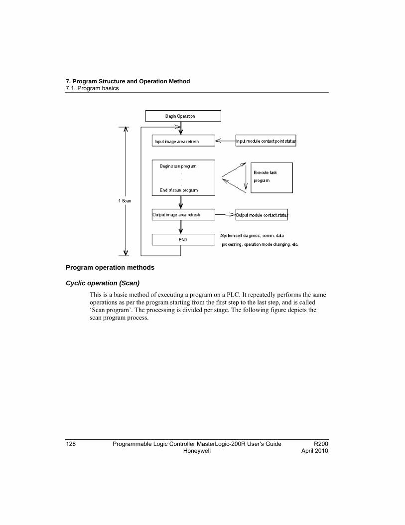
7. Program Structure and Operation Method 7.1. Program basics
128 Programmable Logic Controller MasterLogic-200R User's Guide R200 Honeywell April 2010
Program operation methods
Cyclic operation (Scan)
This is a basic method of executing a program on a PLC. It repeatedly performs the same operations as per the program starting from the first step to the last step, and is called ‘Scan program’. The processing is divided per stage. The following figure depicts the scan program process.

7. Program Structure and Operation Method 7.1. Program basics
R200 Programmable Logic Controller MasterLogic-200R User's Guide 129 April 2010 Honeywell
Stage Processing Description
Operation With the program downloaded into the PLC, the instruction from the user is received.
Initialization processing
The scan processing starts at this stage. It is executed every time when power is applied or when reset command is executed. It involves the following:
I/O module reset
Self-diagnosis execution
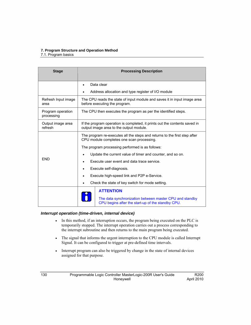
7. Program Structure and Operation Method 7.1. Program basics
130 Programmable Logic Controller MasterLogic-200R User's Guide R200 Honeywell April 2010
Stage Processing Description
Data clear
Address allocation and type register of I/O module
Refresh Input image area
The CPU reads the state of input module and saves it in input image area before executing the program.
Program operation processing
The CPU then executes the program as per the identified steps.
Output image area refresh
If the program operation is completed, it prints out the contents saved in output image area to the output module.
END
The program re-executes all the steps and returns to the first step after CPU module completes one scan processing.
The program processing performed is as follows:
Update the current value of timer and counter, and so on.
Execute user event and data trace service.
Execute self-diagnosis.
Execute high-speed link and P2P e-Service.
Check the state of key switch for mode setting.
ATTENTION
The data synchronization between master CPU and standby CPU begins after the start-up of the standby CPU.
Interrupt operation (time-driven, internal device)
In this method, if an interruption occurs, the program being executed on the PLC is temporarily stopped. The interrupt operation carries out a process corresponding to the interrupt subroutine and then returns to the main program being executed.
The signal that informs the urgent interruption to the CPU module is called Interrupt Signal. It can be configured to trigger at pre-defined time intervals.
Interrupt program can also be triggered by change in the state of internal devices assigned for that purpose.

7. Program Structure and Operation Method 7.1. Program basics
R200 Programmable Logic Controller MasterLogic-200R User's Guide 131 April 2010 Honeywell
Constant scan (fixed period)
In this method all the programs being executed are scanned, after a specific time interval. Scanning stops after all the programs are scanned.
The features that differentiate it with the other programs are the update of input/output and to perform synchronization.
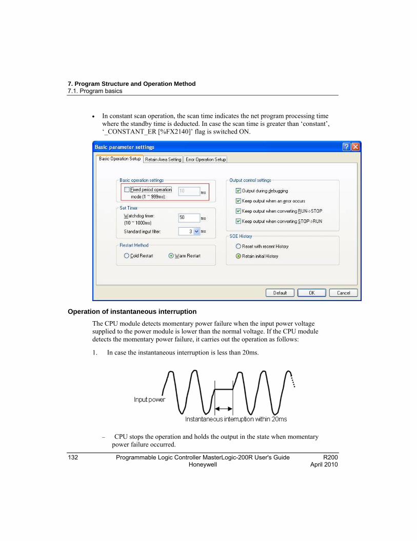
7. Program Structure and Operation Method 7.1. Program basics
132 Programmable Logic Controller MasterLogic-200R User's Guide R200 Honeywell April 2010
In constant scan operation, the scan time indicates the net program processing time where the standby time is deducted. In case the scan time is greater than ‘constant’, ‘_CONSTANT_ER [%FX2140]’ flag is switched ON.
Operation of instantaneous interruption
The CPU module detects momentary power failure when the input power voltage supplied to the power module is lower than the normal voltage. If the CPU module detects the momentary power failure, it carries out the operation as follows:
1. In case the instantaneous interruption is less than 20ms.
CPU stops the operation and holds the output in the state when momentary power failure occurred.
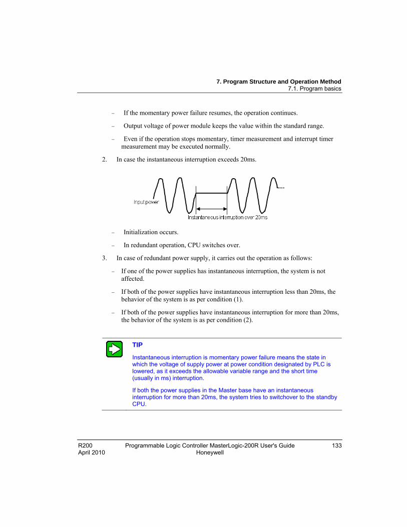
7. Program Structure and Operation Method 7.1. Program basics
R200 Programmable Logic Controller MasterLogic-200R User's Guide 133 April 2010 Honeywell
If the momentary power failure resumes, the operation continues.
Output voltage of power module keeps the value within the standard range.
Even if the operation stops momentary, timer measurement and interrupt timer measurement may be executed normally.
2. In case the instantaneous interruption exceeds 20ms.
Initialization occurs.
In redundant operation, CPU switches over.
3. In case of redundant power supply, it carries out the operation as follows:
If one of the power supplies has instantaneous interruption, the system is not affected.
If both of the power supplies have instantaneous interruption less than 20ms, the behavior of the system is as per condition (1).
If both of the power supplies have instantaneous interruption for more than 20ms, the behavior of the system is as per condition (2).
TIP
Instantaneous interruption is momentary power failure means the state in which the voltage of supply power at power condition designated by PLC is lowered, as it exceeds the allowable variable range and the short time (usually in ms) interruption.
If both the power supplies in the Master base have an instantaneous interruption for more than 20ms, the system tries to switchover to the standby CPU.
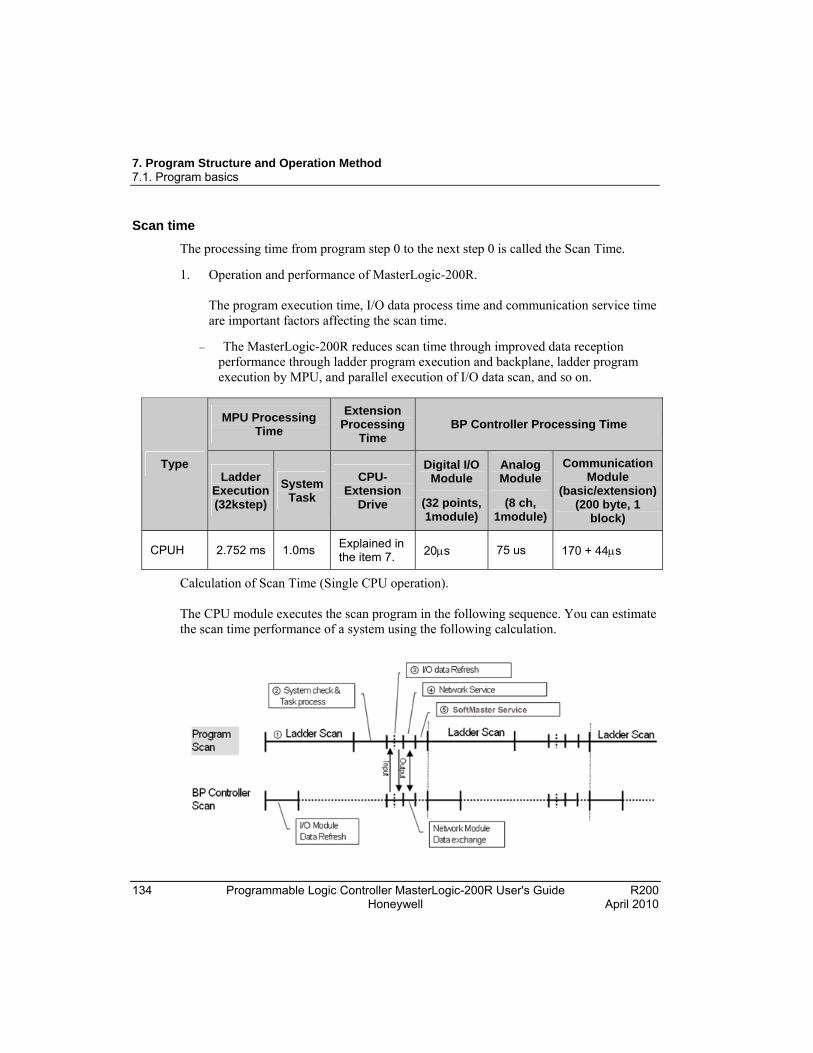
7. Program Structure and Operation Method 7.1. Program basics
134 Programmable Logic Controller MasterLogic-200R User's Guide R200 Honeywell April 2010
Scan time
The processing time from program step 0 to the next step 0 is called the Scan Time.
1. Operation and performance of MasterLogic-200R. The program execution time, I/O data process time and communication service time are important factors affecting the scan time.
The MasterLogic-200R reduces scan time through improved data reception performance through ladder program execution and backplane, ladder program execution by MPU, and parallel execution of I/O data scan, and so on.
MPU Processing Time
Extension Processing
Time BP Controller Processing Time
Type Ladder
Execution (32kstep)
System Task
CPU-Extension
Drive
Digital I/O Module
(32 points, 1module)
Analog Module
(8 ch, 1module)
Communication Module
(basic/extension) (200 byte, 1
block)
CPUH 2.752 ms 1.0ms Explained in the item 7. 20s 75 us 170 + 44s
Calculation of Scan Time (Single CPU operation). The CPU module executes the scan program in the following sequence. You can estimate the scan time performance of a system using the following calculation.

7. Program Structure and Operation Method 7.1. Program basics
R200 Programmable Logic Controller MasterLogic-200R User's Guide 135 April 2010 Honeywell
Scan time (s) = Scan program process system check and task process I/O data refresh network service SoftMaster Service user task program process CPU–extension drive processing
a) Scan program process number of program steps created x 2 x 0.042 (s) *Precise scan time requires in addition of processing time for used instructions. *x 2 refers to the number of average execution code per instruction step.
b) System check and task process: 800s ~ 1.0ms [parameter depending on the usage of auxiliary functions].
c) SoftMaster service process time: 100s at the maximum data monitor. *10% of maximum scan time, there is a setting in the connection settings to improve the process time.
d) Task program process time: Sum of task processing time that occurs within a scan; the time calculation by task programs are the same as of scan program.
e) CPU-extension process time: Synchronization between CPU and extension drive module. *Basic process time (1500s) + number of bases x 250s + 1000s per communication service (HS/P2P) + size of PUTGET (1000s per 1000byte)
Example:
The scan time of a system consisting of a CPU (program 16kstep) + 32 points, 6 I/O modules + 6 analog modules + 4 communication modules (200 bytes, 8 blocks per module) is as follows:
(Two extension bases are used.)
Scan time(s) = ladder execution time + system processing time + digital module I/O processing time + analog I/O processing time + communication module processing time + SoftMaster Service processing time.
= (16000 x 2 x 0.042) + (20 x 6) + (75 x 6) + (185 x 8 x 4) + (100) + (1500 + 250 x 2 + 1000 x 4 + 1000)
= 14934s
= 14.9s

7. Program Structure and Operation Method 7.1. Program basics
136 Programmable Logic Controller MasterLogic-200R User's Guide R200 Honeywell April 2010
2. Scan time monitor. Scan time is saved into the following flag (%F) address/memory areas.
_SCAN_MAX: Maximum value of scan time (resolution of 0.1ms).
_SCAN_MIN: Minimum value of scan time (resolution of 0.1ms).
_SCAN_CUR: Current value of scan time (resolution of 0.1ms).
3. Scan time during redundant operation.
During redundant operation, the data synchronization between the master and the standby CPU and the scan time varies with the data size that you set.
Synchronization data between CPUs: Basic data like system flag, communication flag, and so on. (2.8ms)
Redundancy synchronization area.
a) I/Q base : 1ms/32 bases
7. Program Structure and Operation Method 7.1. Program basics
R200 Programmable Logic Controller MasterLogic-200R User's Guide 137 April 2010 Honeywell
b) M area : 250s per 2kword (16ms for 128kword)
c) R area: 1.5ms per 2kword (12ms for maximum 16kword) (If 2kword of R area is transferred, 2kword of W area is also transferred; hence, a total of 4kword is transferred.)
d) PID block : 0.5ms per block (4ms for 8 PID blocks)
Example:
The scan time of a system consisting of a CPU (program 16kstep) + 32 points, 6 I/O modules + 6 analog modules (PUTGET size of 1000byte) + 4 communication modules (200 bytes 8 blocks per module) is as follows:
(2 extension bases are used, 2kword of M area, 2 PID blocks)
Scan time = Single CPU execution time + Synchronization time
= Single CPU execution time + Sync system data + I/Q base + M area + R area + PID block
= 14.9 + 2.8 + 1.0 + 0.25 + 0.5x2
= 19.95ms
4. Delay in time, to operate in redundancy.
If CPU is added for redundant operation during single CPU mode, the current scan time is momentarily increased by 10%, compared to scan time of single CPU mode. This is to synchronize the data to the standby CPU.
TIP
In single CPU mode including when the standby CPU is in stop mode, data between master and standby CPU is not synchronized, hence, data may be different from each other.
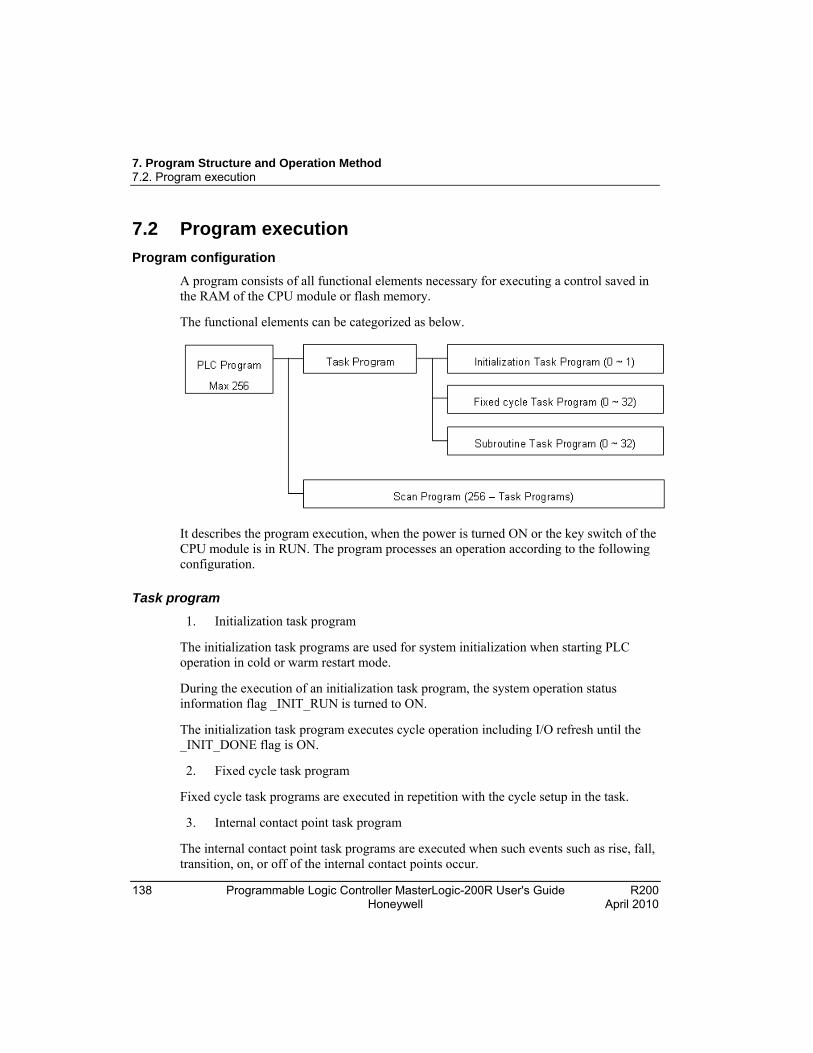
7. Program Structure and Operation Method 7.2. Program execution
138 Programmable Logic Controller MasterLogic-200R User's Guide R200 Honeywell April 2010
7.2 Program execution
Program configuration
A program consists of all functional elements necessary for executing a control saved in the RAM of the CPU module or flash memory.
The functional elements can be categorized as below.
It describes the program execution, when the power is turned ON or the key switch of the CPU module is in RUN. The program processes an operation according to the following configuration.
Task program
1. Initialization task program
The initialization task programs are used for system initialization when starting PLC operation in cold or warm restart mode.
During the execution of an initialization task program, the system operation status information flag _INIT_RUN is turned to ON.
The initialization task program executes cycle operation including I/O refresh until the _INIT_DONE flag is ON.
2. Fixed cycle task program
Fixed cycle task programs are executed in repetition with the cycle setup in the task.
3. Internal contact point task program
The internal contact point task programs are executed when such events such as rise, fall, transition, on, or off of the internal contact points occur.

7. Program Structure and Operation Method 7.2. Program execution
R200 Programmable Logic Controller MasterLogic-200R User's Guide 139 April 2010 Honeywell
The point of time of execution is determined by the condition of event occurrence after the completion of scan program.
Scan program
This program sequentially executes all operations from step 0 to the last step, and is repeated regularly for every scan.
In case interrupt program is running while executing the Scan Program, it stops the program being executed and executes the related interrupt service program.
Restart mode
The restart mode sets up the method of initializing variables and the system at the start-up of PLC operation.
Restart mode has two types; cold and warm restart, which can be set up in the basic parameters of the SoftMaster.

7. Program Structure and Operation Method 7.2. Program execution
140 Programmable Logic Controller MasterLogic-200R User's Guide R200 Honeywell April 2010
When the standby CPU starts up, it executes the initialization according to the restart mode and receives the program and data backup from the master. When set up in flash operation mode, it receives the flash data backup from the master too.
When the standby CPU is switched to master CPU during operation, it is not a restart, therefore, no further action is taken.
The conditions of the execution of the restart modes are as follows:
1. Cold restart
All data is reset (deleted) to ‘0’. Here, the ‘all data’ means the M area, R area, and automation variables. The flag area, such as PID, which does not belong to this category, is not deleted.
Only the variables whose initial values are set up are reset to the initial values.
Even though the parameter is set up to warm restart mode, at the first execution after changing the program to be executed, the next program is executed with cold restart mode.
7. Program Structure and Operation Method 7.2. Program execution
R200 Programmable Logic Controller MasterLogic-200R User's Guide 141 April 2010 Honeywell
Press the manual rest switch for 3 seconds (same as the overall reset of the SoftMaster), the system will start in cold restart mode regardless of the set up restart mode.
2. Warm restart
The data which was set up to maintain previous value maintains the previous value. The data which has user-defined initial value is reset to the initial value. Other data will be deleted to ‘0’.
When set up in warm restart mode, at the first execution, after an interruption by program download or error, is started in cold restart mode.
When set up in warm restart mode, if the data is abnormal (data was not maintained during a power failure), the system is started in cold restart mode.
Press the manual reset switch for less than 5 seconds during power-on, same as the reset instruction in the SoftMaster, if the setting is warm restart mode, the operation begin in warm restart mode.
Data initialization according to the restart modes are as follows:
The variables related with restart mode are default, retain, and initialization variables. The method of initializing the variables in the execution of restart mode is as follows.
Mode
Variable Cold Warm
Default Initialize to ‘0’ Initialize to ‘0’
Retain Initialize to ‘0’ Maintain the previous value
Initialization Initialize to user-defined value
Initialize to user-defined value
Retain and Initialization Initialize to user-defined value
Maintain the previous value
Interrupt task program
This program stops the execution of the scan program and then executes the interrupt service program. The interrupt can be triggered by periodic/non-periodic and internal device signals.
The following are the two types of task programs.
7. Program Structure and Operation Method 7.2. Program execution
142 Programmable Logic Controller MasterLogic-200R User's Guide R200 Honeywell April 2010
Time-driven interrupt task program – Executes according to fixed time intervals.
Internal device interrupt task program – Executes when condition of internal device occurs. The device start condition is detected after the scan program.
Interrupt
The following flowchart illustrates the execution of interrupt programs during execution of regular scan program. It depicts how interrupt tasks are configured in SoftMaster (programming software for MasterLogic-200).
ATTENTION
For additional information on the SoftMaster, refer to SoftMaster User’s Guide.

7. Program Structure and Operation Method 7.2. Program execution
R200 Programmable Logic Controller MasterLogic-200R User's Guide 143 April 2010 Honeywell
TIP
When the power is switched ON, all interrupts are in the Disable state.
Configuring an interrupt task program
Create a task in the project window in SoftMaster, as shown in the following figure and add a program to be performed by each task.

7. Program Structure and Operation Method 7.2. Program execution
144 Programmable Logic Controller MasterLogic-200R User's Guide R200 Honeywell April 2010
REFERENCE - INTERNAL
For additional information on creating an interrupt program, refer to SoftMaster User’s Guide.
Task types
The various task parameters that can be configured using SoftMaster and their functions are as follows:
Type
Spec.
Initialization Fixed Cycle Task Parameters that can be
Configured using SoftMaster and their
Functions are as follows:
(Interval task)
Internal Contact Task
(single task)
Number 1 32 32
Operation condition
When entering RUN mode, prior to start scan program
Fixed cycle (Can be set up to 4294967.295s at the unit of 1ms).
Conditions of internal device designation.
Detection/execution
Execute until the flag _INIT_DONE is ON
Cyclically execute at the pre-defined interval.
Execute by conditional search after completing scan program.

7. Program Structure and Operation Method 7.2. Program execution
R200 Programmable Logic Controller MasterLogic-200R User's Guide 145 April 2010 Honeywell
Type
Spec.
Initialization Fixed Cycle Task Parameters that can be
Configured using SoftMaster and their
Functions are as follows:
(Interval task)
Internal Contact Task
(single task)
Detection delay time
- Delayed as long as a maximum of 0.2ms.
Delayed as long as the maximum scan time.
Execution priority
-- Setting 2 ~ 7 levels
(level 2 is the highest priority)
2 ~ 7 level setting
(2 level is highest priority).
Task number - Assign it between 0~31, so
that it is not duplicated. Assign it between 64~95, so that it is not duplicated.
Processing an interrupt task program
The following points describe the common processing methods and notices for assigning a task program.
1. Features of a task program.
A task program does not reiteratively process like a scan program. It executes only when the execution conditions occur. Consider this aspect when creating a task program.
For instance, if a task program with 10s of fixed cycle is used with a timer and a counter, the timer may have a maximum error of 10s, while the counter checks every 10s. Any counter input changed within 10s is not taken into account.
2. Execution priority
If several tasks are in queue to be executed, it processes from the highest priority task program. If there are several tasks of same priority, they are processed by the order in which they occur.
The task priority is applied only to a task.
Set the priority of task program, considering the program features, importance level, and urgency in execution.
3. Process delay time

7. Program Structure and Operation Method 7.2. Program execution
146 Programmable Logic Controller MasterLogic-200R User's Guide R200 Honeywell April 2010
The delay of task program processing occurs due to the following factors. Consider this aspect when setting a task or creating a program.
Task detection delay. (Refer to details of each task.)
Program execution delay due to the execution of the preceding task program.
4. Correlation between scan program and task program in the initialization.
A user-defined task/scan program does not execute when the initialization task program is executing.
The scan program has a low priority over user-defined task program. Whenever a user-defined task program occurs, the scan program is stopped and the task program execution takes precedence over the scan program.
If user defined tasks frequently occur during the first scan or intensively and intermittently occur, a scan time may increase drastically. Pay special attention while setting the conditions of task.
5. Protection from task program of a currently running program.
If program execution continuity is lost by executing a higher priority program, you can partially protect the task program from being executed, for a problematic part. Currently, a program can be protected by application function commands of ‘DI (task program operation disabled)’ or ‘EI (task program operation enabled)’.
Insert the ‘DI’application function command, into the beginning of a program section to be protected and ‘EI’ to the program section to cancel it. Initialization task is not affected by the application function commands of ‘DI’ and ‘EI’.
TIP
If a task program priority is identical, the program execution follows the order in which the task programs are created.
Processing method of fixed cycle task program
It describes the processing method when a task program is set at the fixed cycle.
1. Task settings
Sets the execution cycle and priority of a task, which is the operation condition of a task program. Check the task number to manage tasks.
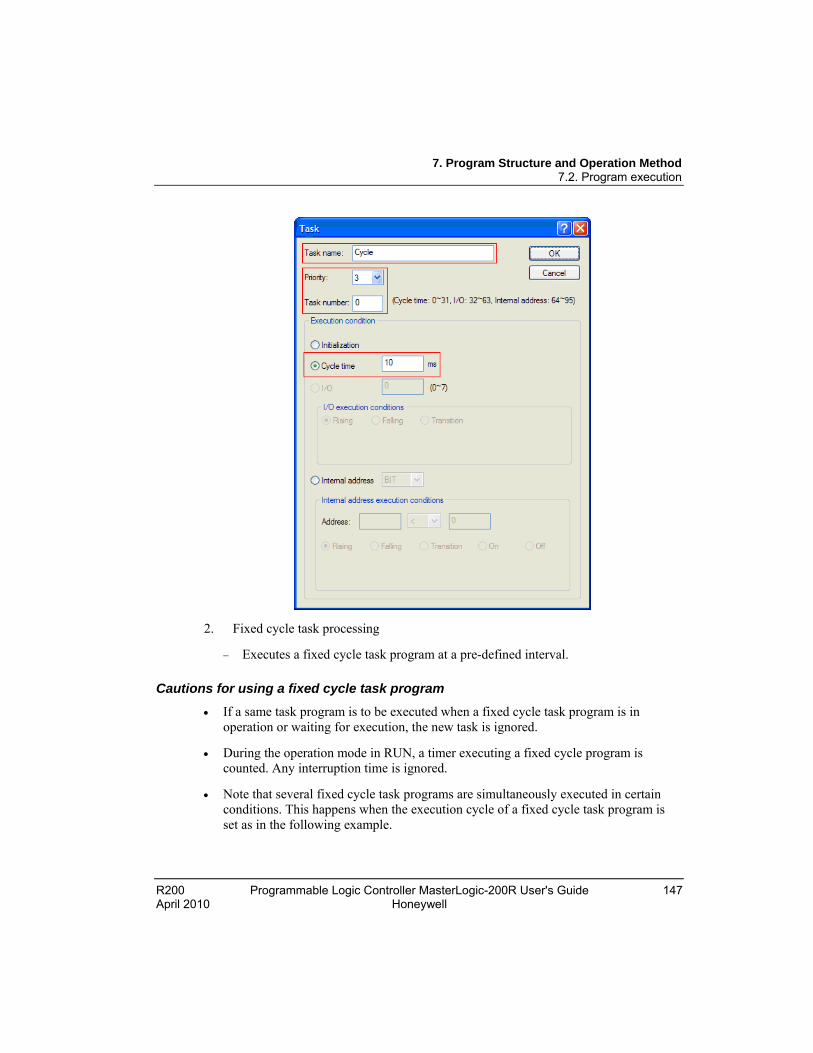
7. Program Structure and Operation Method 7.2. Program execution
R200 Programmable Logic Controller MasterLogic-200R User's Guide 147 April 2010 Honeywell
2. Fixed cycle task processing
Executes a fixed cycle task program at a pre-defined interval.
Cautions for using a fixed cycle task program
If a same task program is to be executed when a fixed cycle task program is in operation or waiting for execution, the new task is ignored.
During the operation mode in RUN, a timer executing a fixed cycle program is counted. Any interruption time is ignored.
Note that several fixed cycle task programs are simultaneously executed in certain conditions. This happens when the execution cycle of a fixed cycle task program is set as in the following example.

7. Program Structure and Operation Method 7.2. Program execution
148 Programmable Logic Controller MasterLogic-200R User's Guide R200 Honeywell April 2010
If you are using four fixed cycle task programs, of which the cycle is 2, 4, 10, and 20s, respectively, it may have simultaneous execution of four programs every 20s. This may result in a longer scan time.
CAUTION
A short fixed cycle is not executed, if the total duration in which the fixed cycle programs are simultaneously executed is greater than the time specified for the simultaneous execution of several fixed cycle tasks.
Ensure that the cycle time of the fixed cycle task is greater than the scan cycle time of the task for successful execution of the task.
Processing method of internal device task program
The internal device task program describes the processing method of an internal device task program, of which, the task (operation condition) execution range is extended from contact to device.
1. Task settings
Set the conditions.
Select the CPU in the Project window.
In SoftMaster, Click Project > Add Item > Task.
Set the priority of a device which is the operation condition of a task program to execute.
Check the task number to manage tasks.
2. Internal device task processing
After a scan program is executed in the CPU module, the task is processed if the conditions of devices (that are the operation conditions of internal device task program) are met, according to the priority.
3. Cautions for using internal device task program
Internal device task program is executed after a scan program is completely executed. Therefore, although a scan program or task program (fixed cycle, external contact) generates the execution conditions of internal device task program, it is not immediately executed.
The execution request of internal device task program checks the conditions of execution when a scan program is completely executed. Therefore, if the

7. Program Structure and Operation Method 7.2. Program execution
R200 Programmable Logic Controller MasterLogic-200R User's Guide 149 April 2010 Honeywell
execution conditions of internal device task occur and disappear by a scan program or task program (fixed cycle, external contact). During the first scan, a task is not executed because it is not detected when the execution conditions are checked.
Task processing in instantaneous interruption
On resuming operation after a long instantaneous interruption, waiting tasks and tasks that occur during the interruption are ignored. On resuming operation, tasks after the interruption are processed.
If an interruption is 20ms or less, a waiting task is executed, after the interruption is over. Any fixed cycle interrupt task that is duplicated during the interruption is ignored.
Verification of task program
After creating a task program, use the following checklist and verify it.
1. Is the task set properly?
If a task occurs excessively or several tasks occur simultaneously in a scan period, it may cause longer scan time or irregularity. If a task setting cannot be changed, check the maximum scan time.
2. Is the task priority well arranged?
A low priority task program may not be processed in a specified time due to a delay in a higher priority task program. When a new task is preceded by a delayed task, it may cause a task collision. The priority must be set in consideration of the urgency of task, execution time, and so on.
3. Is the task program created as short as possible?
A longer execution time of a task program may cause a longer scan time or irregularity. In addition, it may cause task program collision. It is recommended to set the execution time as short as possible (especially, create a fixed cycle task program so that it could be executed within 10% of the shortest task cycle among several tasks.)
4. Is the program for the highest priority task protected during the execution of the program?
If a different task breaks into a task program execution, it completes the current task and then executes the task with the highest priority among waiting tasks. Different tasks breaking into a scan program can be prevented by using ‘DI’/’EI’ application functional commands. It may cause a fault while processing a global
7. Program Structure and Operation Method 7.2. Program execution
150 Programmable Logic Controller MasterLogic-200R User's Guide R200 Honeywell April 2010
parameter process, commonly used with other program or a special or communication module.
Program configuration and example of processing
Register task and program as follows:
Registering a task:
T_SLOW (fixed cycle : = 10ms, Priority := 3 )
PROC_1 (internal contact : = M0, Priority := 5 )
Registering a program:
Program --> P0 (scan program)
Program --> P1 (operating by task T_SLOW)
Program --> P2 (operating by task PROC_1)
If the program execution time and occurrence of external interrupt signal are same:
Execution time of each program: P0 = 21ms, P1 = 2ms and P2 = 7ms,
PROC_1 occurrence: During a scan program, the program is executed as follows:
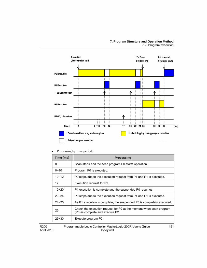
7. Program Structure and Operation Method 7.2. Program execution
R200 Programmable Logic Controller MasterLogic-200R User's Guide 151 April 2010 Honeywell
Processing by time period:
Time (ms) Processing
0 Scan starts and the scan program P0 starts operation.
0~10 Program P0 is executed.
10~12 P0 stops due to the execution request from P1 and P1 is executed.
17 Execution request for P2.
12~20 P1 execution is complete and the suspended P0 resumes.
20~24 P0 stops due to the execution request from P1 and P1 is executed.
24~25 As P1 execution is complete, the suspended P0 is completely executed.
25 Check the execution request for P2 at the moment when scan program (P0) is complete and execute P2.
25~30 Execute program P2.

7. Program Structure and Operation Method 7.2. Program execution
152 Programmable Logic Controller MasterLogic-200R User's Guide R200 Honeywell April 2010
Time (ms) Processing
30~32 P2 stops due to the execution request from P1 and P1 is executed
32~34 As P1 execution is completed at 32, the suspended P2 is executed until 34.
34 Start a new scan (P2 execution starts)
7. Program Structure and Operation Method 7.3. Operation mode
R200 Programmable Logic Controller MasterLogic-200R User's Guide 153 April 2010 Honeywell
7.3 Operation mode
Overview of the operation mode
The 2MLR-CPUH has three operation modes. Each mode describes the operation process at each operation mode.
RUN mode
STOP mode
DEBUG mode
RUN mode
The CPU executes a program operation normally.
WARNING
Changing the operation mode can energize the field and may cause serious threat to human life.
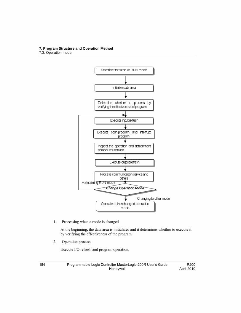
7. Program Structure and Operation Method 7.3. Operation mode
154 Programmable Logic Controller MasterLogic-200R User's Guide R200 Honeywell April 2010
1. Processing when a mode is changed
At the beginning, the data area is initialized and it determines whether to execute it by verifying the effectiveness of the program.
2. Operation process
Execute I/O refresh and program operation.
7. Program Structure and Operation Method 7.3. Operation mode
R200 Programmable Logic Controller MasterLogic-200R User's Guide 155 April 2010 Honeywell
Execute the interrupt program by detecting the operation conditions of the interrupt program.
Inspect the operation and detachment of modules installed.
Process communication service and other internal operations.
STOP mode
The CPU stops when there is no program to run. Program can be controlled from SoftMaster, if the following switches on the CPU module are set:
Remote switch on the CPU module is ON.
RUN/STOP switch on the CPU module is in STOP.
1. Processing when a mode is changed. Remove the output image area and execute refresh. All output data is changed to off state.
2. Operation process
a) Perform an I/O refresh.
b) Inspect the operation and detachment of modules installed.
c) Process communication service and other internal operations.
DEBUG mode
The debug mode is used for finding errors from a program or tracing an operation procedure. The DEBUG mode can be changed only from the STOP mode. In the DEBUG mode, you can verify a program while checking the program execution and data.
Processing when a mode is changed
When the mode is changed, initialize the data area.
Clear the output image area and execute input refresh.
Operation process
Execute I/O refresh.
Debug the operation, depending on the settings.
7. Program Structure and Operation Method 7.3. Operation mode
156 Programmable Logic Controller MasterLogic-200R User's Guide R200 Honeywell April 2010
After debugging the operation until the end of the program, it executes output refresh.
Inspect the operation and detachment of the modules installed.
Process the communication service and other internal operations.
Debug operation conditions. The following are the four conditions in Debug operation and in case it reaches break point, it is possible to set other type of break point.
Operation Condition Description
Execute by one operation unit
(step over)
With operation instruction, it executes only one operation unit and stops.
Execute according to break point
If break point is assigned in the Program, it stops at the assigned break point.
Execute according to the state of contact point
If the contact area desired to be watched and the desired stop state (Read, Write, Value are assigned, it stops when the assigned operation occurs at the assigned contact point).
Execute according to scan times
If scan time to operate is assigned, it operates as per the assigned scan times and stops.
Operation method
a) Set the debug operation conditions in SoftMaster and execute the operation.
b) Interrupt program mode can be set to Enable or Disable state (Enable/Disable) by each interrupt unit.
REFERENCE - INTERNAL
For additional information on operation, refer to Debugging in SoftMaster User’s Guide.

7. Program Structure and Operation Method 7.3. Operation mode
R200 Programmable Logic Controller MasterLogic-200R User's Guide 157 April 2010 Honeywell
Changing operation mode
An operation mode can be changed by the following methods.
Using the mode key of the CPU module.
Using the programming tool (SoftMaster).
Using SoftMaster to change the operation mode of a remote CPU module networked with the main CPU.
Using SoftMaster, HMI and the computer link module, which are networked.
Using the ‘STOP’ command, while a program is operating.
WARNING
Changing the operation mode can energize the field and may cause serious threat to human life.
Setting operation mode
Mode Key Switch Operation Mode
RUN Local RUN
STOP Local STOP
STOP → REM Remote STOP
REM → RUN Local RUN
RUN → REM Remote RUN
REM → STOP Local STOP
Setting remote operation mode
The operation mode can be set as follows:
Mode Key Switch
Mode Change SoftMaster Command
By Communication
Command
Remote STOP → Remote RUN OK OK
Remote STOP → DEBUG OK N/A
REM
Remote RUN → Remote RUN OK OK
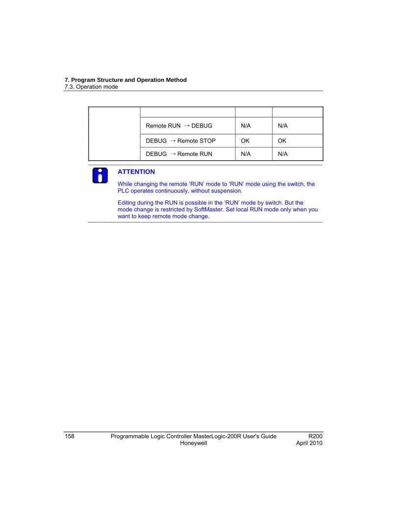
7. Program Structure and Operation Method 7.3. Operation mode
158 Programmable Logic Controller MasterLogic-200R User's Guide R200 Honeywell April 2010
Remote RUN → DEBUG N/A N/A
DEBUG → Remote STOP OK OK
DEBUG → Remote RUN N/A N/A
ATTENTION
While changing the remote ‘RUN’ mode to ‘RUN’ mode using the switch, the PLC operates continuously, without suspension.
Editing during the RUN is possible in the ‘RUN’ mode by switch. But the mode change is restricted by SoftMaster. Set local RUN mode only when you want to keep remote mode change.

7. Program Structure and Operation Method 7.4. Redundant system operation
R200 Programmable Logic Controller MasterLogic-200R User's Guide 159 April 2010 Honeywell
7.4 Redundant system operation
Redundant operation mode
In a redundant system, there is a synchronization cable for data transfer between CPUs and each CPU module has a key switch.
The following table defines the operation status of redundant system.
Sync Cable Between CPU
Current Status
CPU-A(B) Operation
Mode
CPU-B(A) Operation Mode
Remarks
Standalone Operation
RUN STOP CPU-A or CPU-B is in RUN mode.
Redundant Operation
RUN RUN CPU-A and CPU-B is in redundant operation mode with master and standby configuration.
Connected
STOP STOP STOP CPU-A and CPU-B is in redundant operation mode but operation is in STOP mode.
Disconnected Standalone Operation
RUN/STOP
- Single CPU mode.
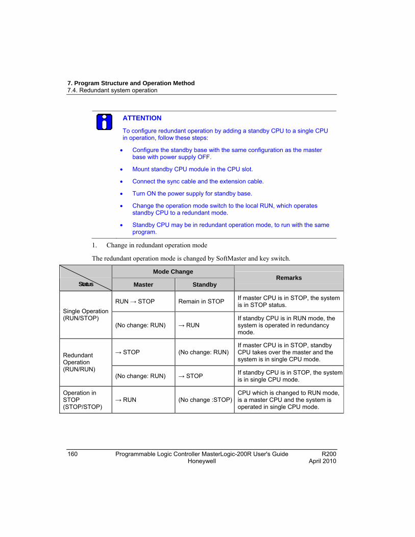
7. Program Structure and Operation Method 7.4. Redundant system operation
160 Programmable Logic Controller MasterLogic-200R User's Guide R200 Honeywell April 2010
ATTENTION
To configure redundant operation by adding a standby CPU to a single CPU in operation, follow these steps:
Configure the standby base with the same configuration as the master base with power supply OFF.
Mount standby CPU module in the CPU slot.
Connect the sync cable and the extension cable.
Turn ON the power supply for standby base.
Change the operation mode switch to the local RUN, which operates standby CPU to a redundant mode.
Standby CPU may be in redundant operation mode, to run with the same program.
1. Change in redundant operation mode
The redundant operation mode is changed by SoftMaster and key switch.
Mode Change
Status Master Standby Remarks
RUN → STOP Remain in STOP If master CPU is in STOP, the system is in STOP status.
Single Operation (RUN/STOP)
(No change: RUN) → RUN If standby CPU is in RUN mode, the system is operated in redundancy mode.
→ STOP (No change: RUN) If master CPU is in STOP, standby CPU takes over the master and the system is in single CPU mode.
Redundant Operation (RUN/RUN)
(No change: RUN) → STOP If standby CPU is in STOP, the system is in single CPU mode.
Operation in STOP (STOP/STOP)
→ RUN (No change :STOP)CPU which is changed to RUN mode, is a master CPU and the system is operated in single CPU mode.
7. Program Structure and Operation Method 7.4. Redundant system operation
R200 Programmable Logic Controller MasterLogic-200R User's Guide 161 April 2010 Honeywell
2. Change in master during redundant operation
Condition for automatic switchover
i. Power supplies of master is turned OFF
ii. Master CPU is in STOP due to faulty operation
iii. Module is detached from the master base
iv. Fault in the CPU (CPU detach)
v. Module in the extension base is detached
vi. System error in the master CPU (abnormal completion of CPU and scan watchdog error)
Condition for manual switchover
i. Key switch in the master CPU is set to STOP
ii. CPU mode is changed to STOP by SoftMaster
iii. Master switchover command from SoftMaster
iv. MST_CHG instruction
v. Module in the extension base is detached
vi. System error in the master CPU (abnormal completion of CPU and scan watchdog error)
Condition in which switchover does not take place
i. Failure in redundant power supply
ii. Standby CPU is already faulty when there is a fault in the master CPU - The system stops, if the same fault occurs. - Switchover does not take place, if there is a mask flag set for error.
iii. Standby CPU is not in RUN mode
7. Program Structure and Operation Method 7.4. Redundant system operation
162 Programmable Logic Controller MasterLogic-200R User's Guide R200 Honeywell April 2010
Startup of redundant system
1. Creating a program
Create a program using SoftMaster
Write program to PLC
2. Startup method
By local key After setting a key switch to REM and write the program to PLC, set a key switch to RUN.
By SoftMaster After setting a key switch to REM, select RUN in the Online menu.
By turning on the power supply Set the key switch to RUN and turn on the power supply. If the system is in remote RUN before the shutdown, turning on the power supply starts the system operation.
By reset There are two ways to restart the system: Reset and Overall reset i) Reset: Press the reset switch in front of CPU module for less than 3s and dot matrix of CPU module shows RST. This has the same effect as the power on/off. ii) Overall Reset: Press the reset switch for more than 3s and dot matrix of CPU module shows RSTC. The system restarts in the cold restart mode.
3. Initial startup
This is the system settings and startup method for the very first operation.
Create a required program.
Set synchronization area in the redundancy parameter.
When program is completed, check for availability by compiling.
Download the program using a communication port in the CPU module.
Change the Master CPU to a RUN mode using a key switch or SoftMaster.
Change the Standby CPU to a RUN mode and enable redundant operation.

7. Program Structure and Operation Method 7.4. Redundant system operation
R200 Programmable Logic Controller MasterLogic-200R User's Guide 163 April 2010 Honeywell
Stop Master CPU and check for switchover.
4. Standby CPU participation in redundant operation
Synchronizes the standby CPU as per the following method:
Initialize CPU *.
Check for redundant configuration *.
Transfer fixed data from the master CPU *.
Transfer variable from the master CPU **.
Check for synchronization **.
Operate in redundant mode at the same time as the master CPU **.
ATTENTION
Redundant operation mode and parameter settings are described in the Redundant System Operation Mode section.
* indicates the tasks are executed separately so that each scan time does not exceed 50ms.
** indicates the tasks are executed at every scan and do not exceed a scan time of 50ms. (Around 50ms can be exceeded with number of variables exceeding the standard value. Refer to section, Scan time.)
5. Details of standby CPU participation in redundant operation
a) Turn ON the power supply.
Check for master CPU operation.
Check for Standby participation mode.
Check for CPU self-diagnosis.
Check for Program transfer from master (record in RAM, memory module).
b) Check for redundant configuration.
Check for IO access.
7. Program Structure and Operation Method 7.4. Redundant system operation
164 Programmable Logic Controller MasterLogic-200R User's Guide R200 Honeywell April 2010
Check for IO module information transferred from master.
Scan IO module information in the standby.
Compare with IO parameter settings.
c) Transfer fixed data from master.
Receive flag details from master (separately transferred, if necessary).
Check if flags are unchanged and proceed to step (d).
d) Transfer variables from master.
User data area and system buffer.
e) Check for synchronization with master.
Synchronize internal operation details of CPU.
f) Operate in redundant mode at the same time as the master CPU.
Start at input refresh.
6. Operation by startup condition.
a) Normal startup.
Master CPU checks for system configuration when the power is supplied. When the power supply is delayed for extension base, the base is displayed in the dot matrix as ‘Eb-xx’ and waits for power supply.
For stop mode, the system changes to stop mode after 10s.
Initial operation starts with cold restart after the change in program.
The system which is stopped in a normal condition restarts as per parameter settings (Example: Key switch, SoftMaster, Power on/off and reset).
To restart the system previously set in warn restart mode to a cold restart mode, reset key, SoftMaster, Overall reset may be used.
In case operation is stopped by an error, restart method is determined by type of error or error remedy. (Refer to section Troubleshooting).
b) In case of I/O skip
The error check does not include the module with I/O skip and the module is in operation only when I/O skip is removed. Refer to I/O module skip function .

7. Program Structure and Operation Method 7.4. Redundant system operation
R200 Programmable Logic Controller MasterLogic-200R User's Guide 165 April 2010 Honeywell
c) In case of fault mask
The error check includes the module with fault mask. However, the operation continues if there is a module mismatch error. Refer to Fault mask function .
If whole base is masked with base power turned off, CPU is in wait status for the power supply.
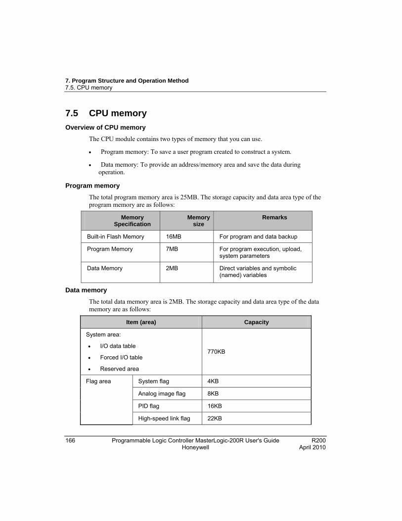
7. Program Structure and Operation Method 7.5. CPU memory
166 Programmable Logic Controller MasterLogic-200R User's Guide R200 Honeywell April 2010
7.5 CPU memory
Overview of CPU memory
The CPU module contains two types of memory that you can use.
Program memory: To save a user program created to construct a system.
Data memory: To provide an address/memory area and save the data during operation.
Program memory
The total program memory area is 25MB. The storage capacity and data area type of the program memory are as follows:
Memory Specification
Memory size
Remarks
Built-in Flash Memory 16MB For program and data backup
Program Memory 7MB For program execution, upload, system parameters
Data Memory 2MB Direct variables and symbolic (named) variables
Data memory
The total data memory area is 2MB. The storage capacity and data area type of the data memory are as follows:
Item (area) Capacity
System area:
I/O data table
Forced I/O table
Reserved area
770KB
System flag 4KB
Analog image flag 8KB
PID flag 16KB
Flag area
High-speed link flag 22KB
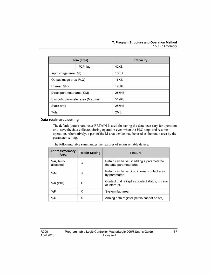
7. Program Structure and Operation Method 7.5. CPU memory
R200 Programmable Logic Controller MasterLogic-200R User's Guide 167 April 2010 Honeywell
Item (area) Capacity
P2P flag 42KB
Input image area (%I) 16KB
Output image area (%Q) 16KB
R area (%R) 128KB
Direct parameter area(%M) 256KB
Symbolic parameter area (Maximum) 512KB
Stack area 256KB
Total 2MB
Data retain area setting
The default (auto.) parameter RETAIN is used for saving the data necessary for operation or to save the data collected during operation even when the PLC stops and resumes operation. Alternatively, a part of the M area device may be used as the retain area by the parameter setting.
The following table summarizes the features of retain settable device.
Address/Memory Area
Retain Setting Feature
%A, Auto-allocated
O Retain can be set, if adding a parameter to the auto parameter area.
%M O Retain can be set, into internal contact area by parameter.
%K (PID) X Contact that is kept as contact status, in case of interrupt.
%F X System flag area.
%U X Analog data register (retain cannot be set).
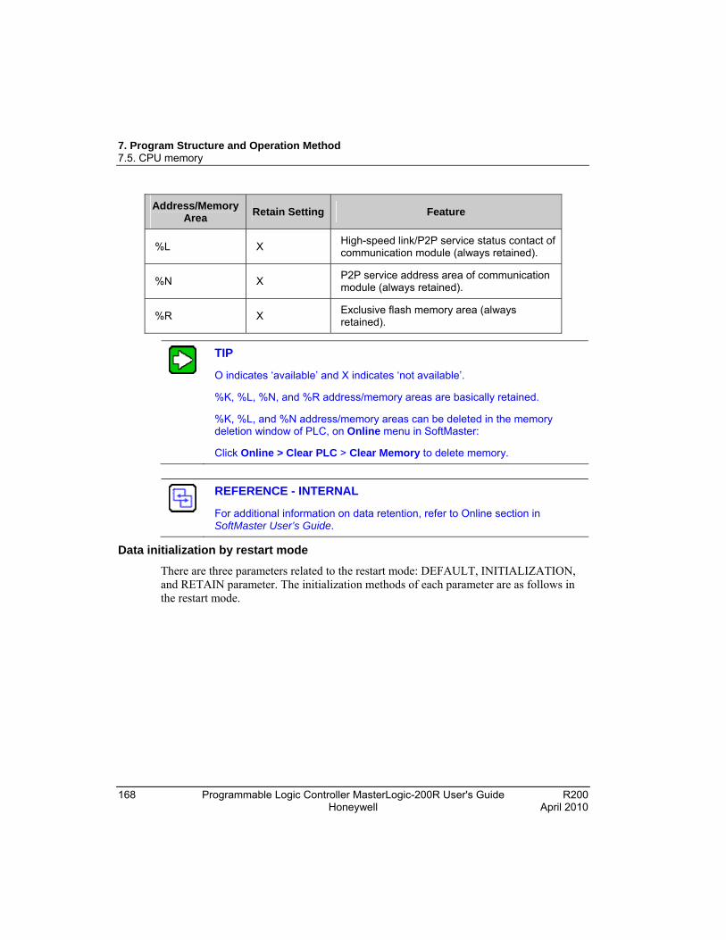
7. Program Structure and Operation Method 7.5. CPU memory
168 Programmable Logic Controller MasterLogic-200R User's Guide R200 Honeywell April 2010
Address/Memory Area
Retain Setting Feature
%L X High-speed link/P2P service status contact of communication module (always retained).
%N X P2P service address area of communication module (always retained).
%R X Exclusive flash memory area (always retained).
TIP
O indicates ‘available’ and X indicates ‘not available’.
%K, %L, %N, and %R address/memory areas are basically retained.
%K, %L, and %N address/memory areas can be deleted in the memory deletion window of PLC, on Online menu in SoftMaster:
Click Online > Clear PLC > Clear Memory to delete memory.
REFERENCE - INTERNAL
For additional information on data retention, refer to Online section in SoftMaster User’s Guide.
Data initialization by restart mode
There are three parameters related to the restart mode: DEFAULT, INITIALIZATION, and RETAIN parameter. The initialization methods of each parameter are as follows in the restart mode.
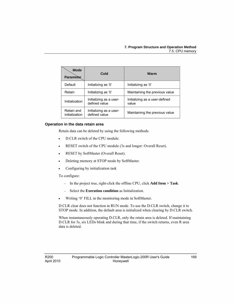
7. Program Structure and Operation Method 7.5. CPU memory
R200 Programmable Logic Controller MasterLogic-200R User's Guide 169 April 2010 Honeywell
Operation in the data retain area
Retain data can be deleted by using the following methods.
D.CLR switch of the CPU module.
RESET switch of the CPU module (3s and longer: Overall Reset).
RESET by SoftMaster (Overall Reset).
Deleting memory at STOP mode by SoftMaster.
Configuring by initialization task
To configure:
In the project tree, right-click the offline CPU, click Add Item > Task.
Select the Execution condition as Initialization.
Writing ‘0’ FILL in the monitoring mode in SoftMaster.
D.CLR clear does not function in RUN mode. To use the D.CLR switch, change it to STOP mode. In addition, the default area is initialized when clearing by D.CLR switch.
When instantaneously operating D.CLR, only the retain area is deleted. If maintaining D.CLR for 3s, six LEDs blink and during that time, if the switch returns, even R area data is deleted.
Mode
Parameter Cold Warm
Default Initializing as ‘0’ Initializing as ‘0’
Retain Initializing as ‘0’ Maintaining the previous value
Initialization Initializing as a user-defined value
Initializing as a user-defined value
Retain and initialization
Initializing as a user-defined value
Maintaining the previous value

7. Program Structure and Operation Method 7.5. CPU memory
170 Programmable Logic Controller MasterLogic-200R User's Guide R200 Honeywell April 2010
For the maintenance or reset (clear) of the retain area data according to the PLC operation, refer to the following table.
Operation Retain M Area Retain R Area Retain
Reset Maintaining the previous value
Maintaining the previous value
Maintaining the previous value
Over all reset Initializing as ‘0’ Initializing as ‘0’ Maintaining the previous value
D.CLR Initializing as ‘0’ Initializing as ‘0’ Maintaining the previous value
D.CLR (3s) Initializing as ‘0’ Initializing as ‘0’ Initializing as ‘0’
STOP→RUN Maintaining the previous value
Maintaining the previous value
Maintaining the previous value
TIP
Default variable: A variable is not set to maintain the initial/previous value.
Initialization (INIT) variable: A variable is set to maintain the initial value.
Retain variable: A variable is set to maintain the previous value.
Data initialization
Every device memory is cleared up as ‘0’ when memory deletion occurs. The data value may be assigned initially depending on a system and the initialization task required must be used.
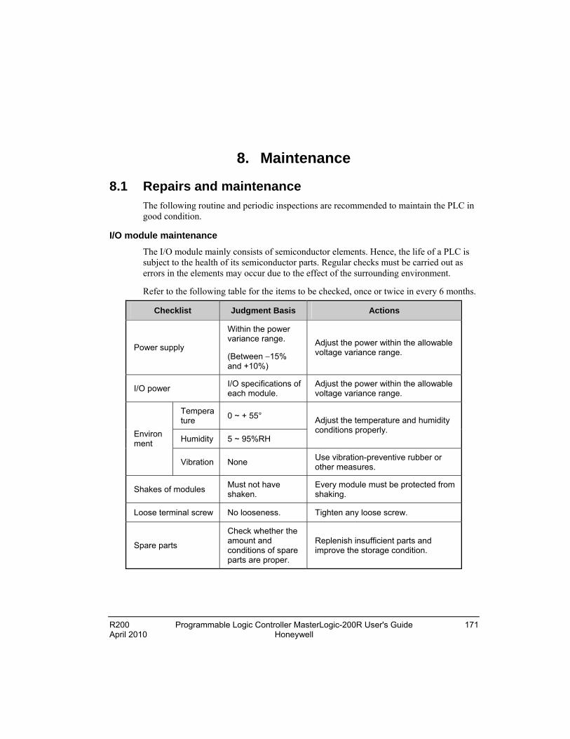
R200 Programmable Logic Controller MasterLogic-200R User's Guide 171 April 2010 Honeywell
8. Maintenance
8.1 Repairs and maintenance The following routine and periodic inspections are recommended to maintain the PLC in good condition.
I/O module maintenance
The I/O module mainly consists of semiconductor elements. Hence, the life of a PLC is subject to the health of its semiconductor parts. Regular checks must be carried out as errors in the elements may occur due to the effect of the surrounding environment.
Refer to the following table for the items to be checked, once or twice in every 6 months.
Checklist Judgment Basis Actions
Power supply
Within the power variance range.
(Between 15% and +10%)
Adjust the power within the allowable voltage variance range.
I/O power I/O specifications of each module.
Adjust the power within the allowable voltage variance range.
Temperature
0 ~ + 55°
Humidity 5 ~ 95%RH
Adjust the temperature and humidity conditions properly. Environ
ment
Vibration None Use vibration-preventive rubber or other measures.
Shakes of modules Must not have shaken.
Every module must be protected from shaking.
Loose terminal screw No looseness. Tighten any loose screw.
Spare parts
Check whether the amount and conditions of spare parts are proper.
Replenish insufficient parts and improve the storage condition.
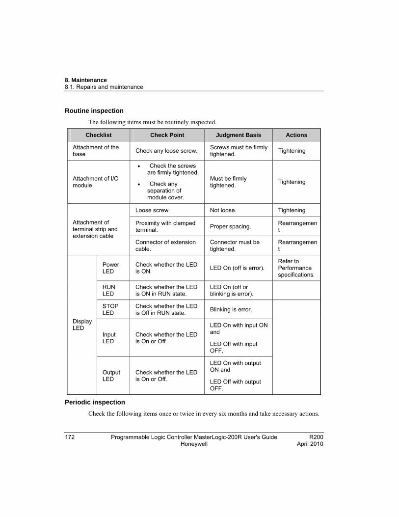
8. Maintenance 8.1. Repairs and maintenance
172 Programmable Logic Controller MasterLogic-200R User's Guide R200 Honeywell April 2010
Routine inspection
The following items must be routinely inspected.
Checklist Check Point Judgment Basis Actions
Attachment of the base
Check any loose screw. Screws must be firmly tightened.
Tightening
Attachment of I/O module
Check the screws are firmly tightened.
Check any separation of module cover.
Must be firmly tightened.
Tightening
Loose screw. Not loose. Tightening
Proximity with clamped terminal.
Proper spacing. Rearrangement
Attachment of terminal strip and extension cable
Connector of extension cable.
Connector must be tightened.
Rearrangement
Power LED
Check whether the LED is ON.
LED On (off is error). Refer to Performance specifications.
RUN LED
Check whether the LED is ON in RUN state.
LED On (off or blinking is error).
STOP LED
Check whether the LED is Off in RUN state.
Blinking is error.
Input LED
Check whether the LED is On or Off.
LED On with input ON and
LED Off with input OFF.
Display LED
Output LED
Check whether the LED is On or Off.
LED On with output ON and
LED Off with output OFF.
Periodic inspection
Check the following items once or twice in every six months and take necessary actions.

8. Maintenance 8.1. Repairs and maintenance
R200 Programmable Logic Controller MasterLogic-200R User's Guide 173 April 2010 Honeywell
Checklist Check Method Judgment Basis Actions
Temperature 0 ~ 55 C
Humidity 5 ~ 95%RH Environment
Contamination level
Measure by thermometer/hygrometer.
Measure corrosive gas.
Free of corrosive gas.
Adjusting according to the general spec (environmental condition in the panel).
Loose Module/shake
Try to carefully feel the movement of each module.
Must be firmly attached.
Tightening.
PLC status
Built-in dust/impurities
Visual inspection.
No built-in dust/impurities.
-
Loose connector
Tightening with a screwdriver.
No loosened screws.
Tightening.
Proximity of clamped terminal
Visual inspection.
Proper spacing. Rearrangement. Connector status
Loosened connector
Visual inspection.
No looseness. Tightening connector screws.
Check power voltage
Check the voltage of input terminal by using a multimeter.
AC100~240V:AC85~ 264V
DC24V:DC19.2 ~ 28.8V
Change the power supply.
Battery
Check the battery replacement timing and voltage drop.
Check the total interruption time and warranty period.
No battery voltage drop display.
A battery must be replaced, if the warranty period has expired despite no display.

8. Maintenance 8.1. Repairs and maintenance
174 Programmable Logic Controller MasterLogic-200R User's Guide R200 Honeywell April 2010
Checklist Check Method Judgment Basis Actions
Fuse Visual inspection.
No fuse blown condition.
To be replaced regularly because element may have deteriorated due to inrush current.
R200 Programmable Logic Controller MasterLogic-200R User's Guide 175 April 2010 Honeywell
9. Troubleshooting
9.1 Introduction This chapter describes types of potential errors that occur while operating the system, causes of errors, ways to detect them, and corrective measures.
9.2 Basic troubleshooting procedure To improve the reliability of a system, it is important to take corrective measures promptly, when a trouble/fault occurs. To recover the system from the fault immediately, it is most important to quickly detect the potential causes of a fault and take corrective measures. To troubleshoot the system correctly, ensure the following cautions and procedures.
1. Check the following manually.
a) Operation status (Stop and Run).
a) Power On/Off status.
b) I/O device status.
c) Wiring status (I/O wiring, extension, and communication cable).
d) The status of each displays (POWER LED, RUN/STOP LED, I/O LED, and so on), connect to peripherals, and check the operation condition and program.
2. Check for any abnormality. Observe how a fault changes by executing the following:
a) Move the key switch to STOP and turn it On/Off.
3. Restricting range. Estimate by which factor, a fault occurs:
a) Is it from the PLC or external factor?
b) I/O module or others?
c) PLC program?
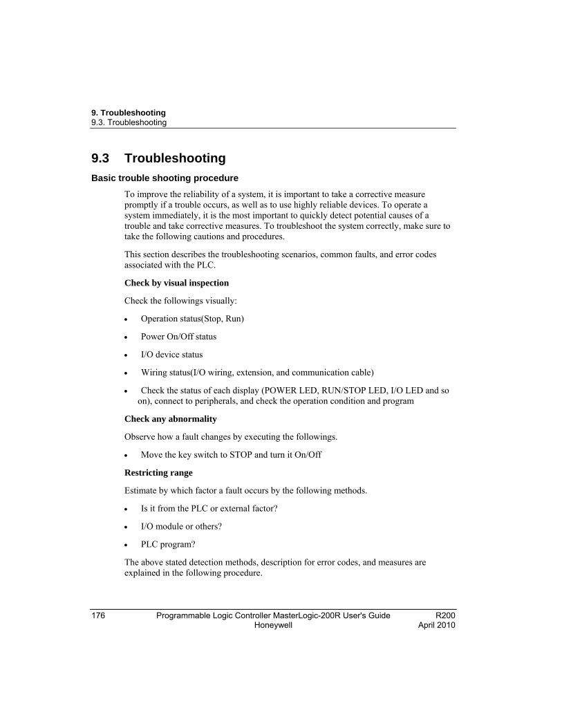
9. Troubleshooting 9.3. Troubleshooting
176 Programmable Logic Controller MasterLogic-200R User's Guide R200 Honeywell April 2010
9.3 Troubleshooting
Basic trouble shooting procedure
To improve the reliability of a system, it is important to take a corrective measure promptly if a trouble occurs, as well as to use highly reliable devices. To operate a system immediately, it is the most important to quickly detect potential causes of a trouble and take corrective measures. To troubleshoot the system correctly, make sure to take the following cautions and procedures.
This section describes the troubleshooting scenarios, common faults, and error codes associated with the PLC.
Check by visual inspection
Check the followings visually:
Operation status(Stop, Run)
Power On/Off status
I/O device status
Wiring status(I/O wiring, extension, and communication cable)
Check the status of each display (POWER LED, RUN/STOP LED, I/O LED and so on), connect to peripherals, and check the operation condition and program
Check any abnormality
Observe how a fault changes by executing the followings.
Move the key switch to STOP and turn it On/Off
Restricting range
Estimate by which factor a fault occurs by the following methods.
Is it from the PLC or external factor?
I/O module or others?
PLC program?
The above stated detection methods, description for error codes, and measures are explained in the following procedure.

9. Troubleshooting 9.3. Troubleshooting
R200 Programmable Logic Controller MasterLogic-200R User's Guide 177 April 2010 Honeywell
Action when POWER LED is OFF
This section describes the sequence of steps to be taken, if the POWER LED is OFF.

9. Troubleshooting 9.3. Troubleshooting
178 Programmable Logic Controller MasterLogic-200R User's Guide R200 Honeywell April 2010

9. Troubleshooting 9.3. Troubleshooting
R200 Programmable Logic Controller MasterLogic-200R User's Guide 179 April 2010 Honeywell
Action when WAR (Warning) LED is ON
This section describes the orders of taking a measure if WAR.LED is On, when turning it on, starting operation or operating.

9. Troubleshooting 9.3. Troubleshooting
180 Programmable Logic Controller MasterLogic-200R User's Guide R200 Honeywell April 2010
CAUTION
If warning error occurs, the PLC system does not stop but it is necessary to check the error message and take a corrective measure or it may cause an error.
It describes measure when WAR.LED is on because redundant system runs in single or configure b line mode.
1. Connect to SoftMaster.
2. Click Monitor > System Monitoring. The System Monitoring window appears.
3. Click PLC > System Configuration as shown below..
The following figure illustrates system configuration (in case of ring configuration).

9. Troubleshooting 9.3. Troubleshooting
R200 Programmable Logic Controller MasterLogic-200R User's Guide 181 April 2010 Honeywell
The following figure illustrates system configuration (in case of line configuration).
In case system is configured as ring, basic base and extension base is displayed by ring like structure. In case system is configured as line, disconnection between bases is displayed. This can be checked by LED. In case system starts with line topology, RING LED turns off. In case it starts with ring topology and it changes the topology to line, RING LED flickers
The following figure illustrates the CPU module LED.
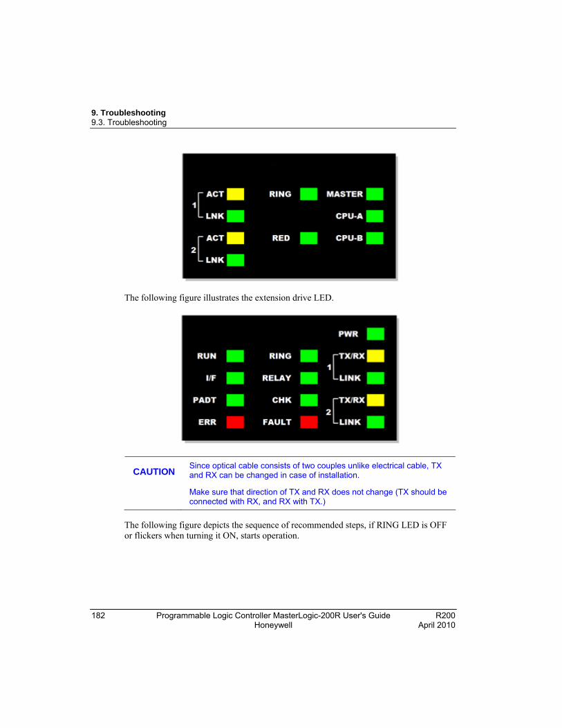
9. Troubleshooting 9.3. Troubleshooting
182 Programmable Logic Controller MasterLogic-200R User's Guide R200 Honeywell April 2010
The following figure illustrates the extension drive LED.
CAUTION
Since optical cable consists of two couples unlike electrical cable, TX and RX can be changed in case of installation.
Make sure that direction of TX and RX does not change (TX should be connected with RX, and RX with TX.)
The following figure depicts the sequence of recommended steps, if RING LED is OFF or flickers when turning it ON, starts operation.
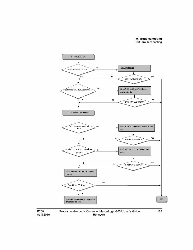
9. Troubleshooting 9.3. Troubleshooting
R200 Programmable Logic Controller MasterLogic-200R User's Guide 183 April 2010 Honeywell
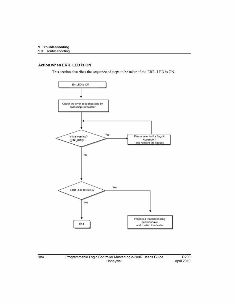
9. Troubleshooting 9.3. Troubleshooting
184 Programmable Logic Controller MasterLogic-200R User's Guide R200 Honeywell April 2010
Action when ERR. LED is ON
This section describes the sequence of steps to be taken if the ERR. LED is ON.
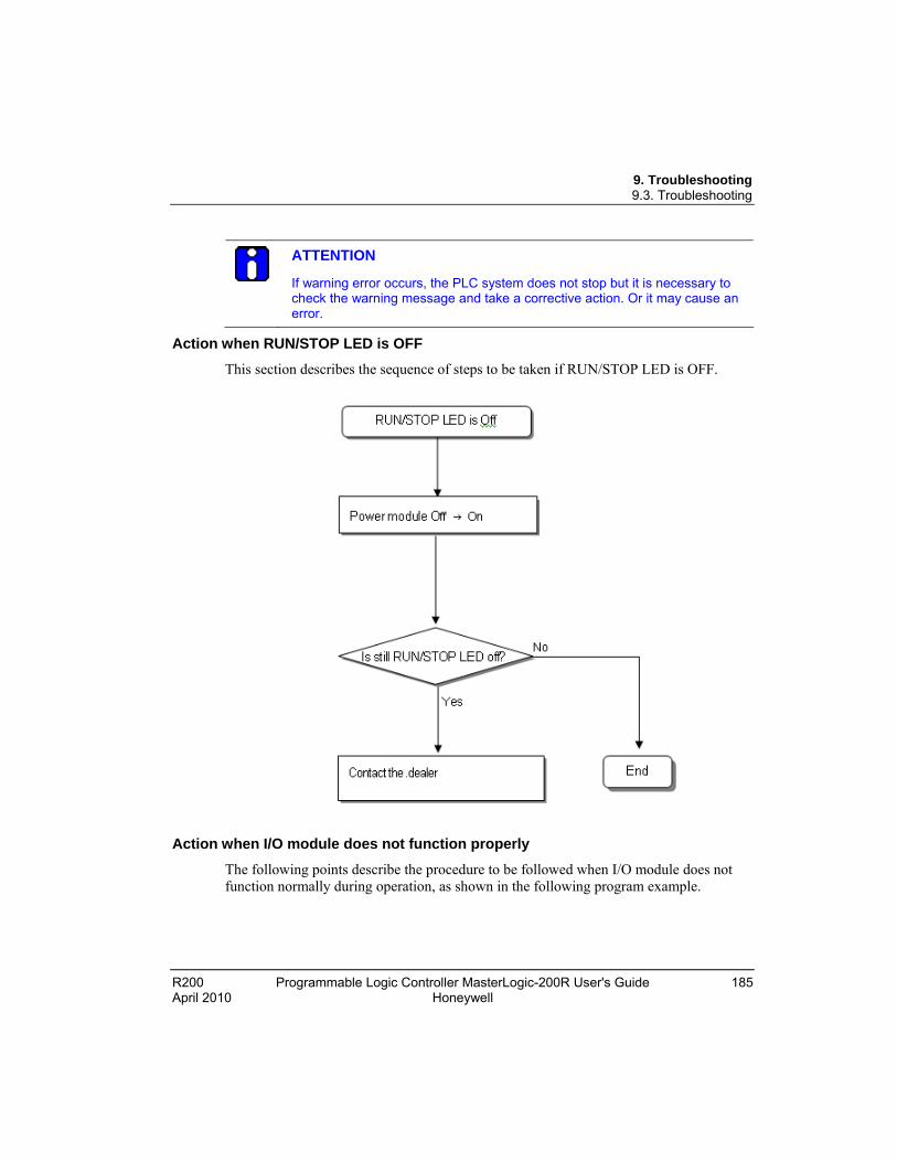
9. Troubleshooting 9.3. Troubleshooting
R200 Programmable Logic Controller MasterLogic-200R User's Guide 185 April 2010 Honeywell
ATTENTION
If warning error occurs, the PLC system does not stop but it is necessary to check the warning message and take a corrective action. Or it may cause an error.
Action when RUN/STOP LED is OFF
This section describes the sequence of steps to be taken if RUN/STOP LED is OFF.
Action when I/O module does not function properly
The following points describe the procedure to be followed when I/O module does not function normally during operation, as shown in the following program example.
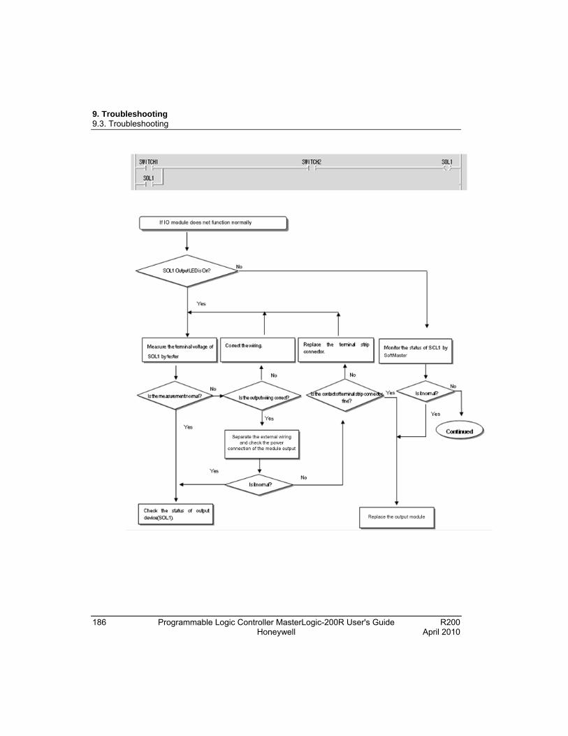
9. Troubleshooting 9.3. Troubleshooting
186 Programmable Logic Controller MasterLogic-200R User's Guide R200 Honeywell April 2010
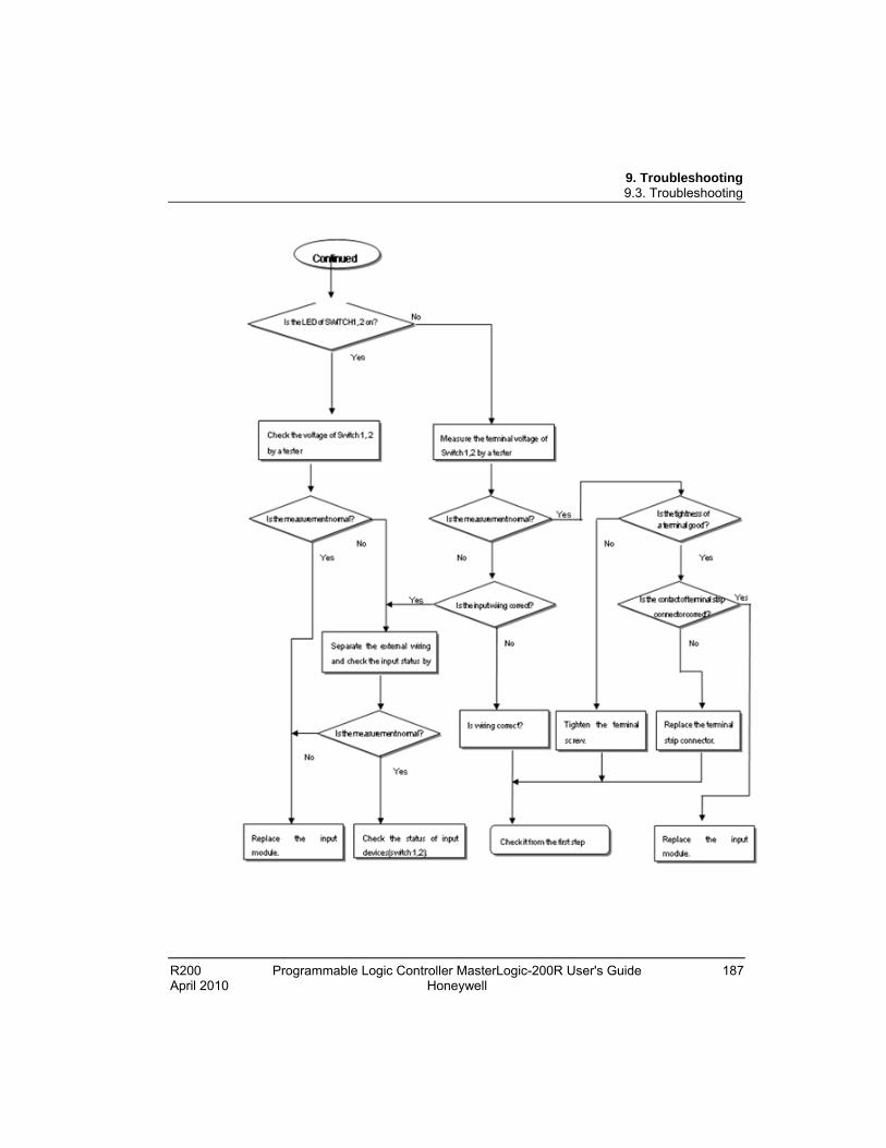
9. Troubleshooting 9.3. Troubleshooting
R200 Programmable Logic Controller MasterLogic-200R User's Guide 187 April 2010 Honeywell

9. Troubleshooting 9.3. Troubleshooting
188 Programmable Logic Controller MasterLogic-200R User's Guide R200 Honeywell April 2010
Action when writing a program to the CPU fails
Use the following sequence of steps when writing a program to the CPU module fails.
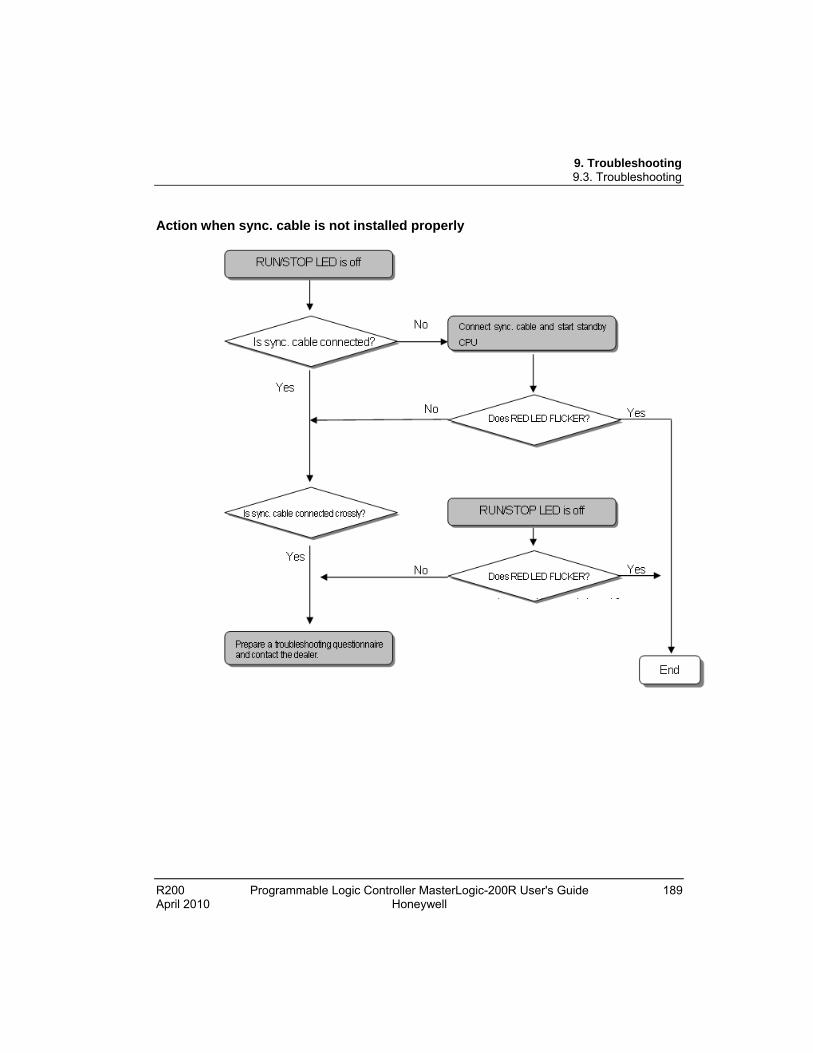
9. Troubleshooting 9.3. Troubleshooting
R200 Programmable Logic Controller MasterLogic-200R User's Guide 189 April 2010 Honeywell
Action when sync. cable is not installed properly

9. Troubleshooting 9.3. Troubleshooting
190 Programmable Logic Controller MasterLogic-200R User's Guide R200 Honeywell April 2010
Action when undesirable master switching occurs

9. Troubleshooting 9.3. Troubleshooting
R200 Programmable Logic Controller MasterLogic-200R User's Guide 191 April 2010 Honeywell
Action when newly added CPU does not join redundant operation
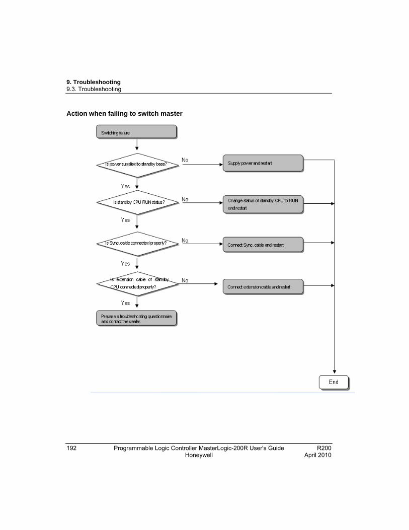
9. Troubleshooting 9.3. Troubleshooting
192 Programmable Logic Controller MasterLogic-200R User's Guide R200 Honeywell April 2010
Action when failing to switch master
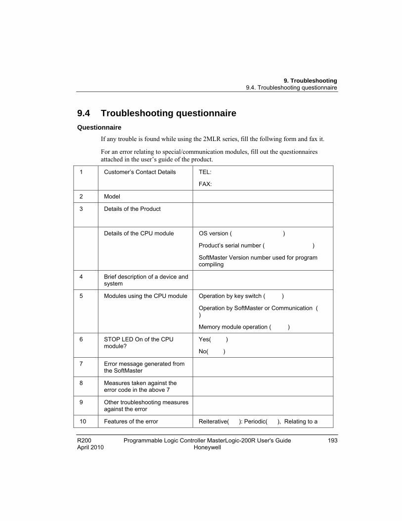
9. Troubleshooting 9.4. Troubleshooting questionnaire
R200 Programmable Logic Controller MasterLogic-200R User's Guide 193 April 2010 Honeywell
9.4 Troubleshooting questionnaire
Questionnaire
If any trouble is found while using the 2MLR series, fill the follwing form and fax it.
For an error relating to special/communication modules, fill out the questionnaires attached in the user’s guide of the product.
1 Customer’s Contact Details TEL:
FAX:
2 Model
3 Details of the Product
Details of the CPU module OS version ( )
Product’s serial number ( )
SoftMaster Version number used for program compiling
4 Brief description of a device and system
5 Modules using the CPU module Operation by key switch ( )
Operation by SoftMaster or Communication ( )
Memory module operation ( )
6 STOP LED On of the CPU module?
Yes( )
No( )
7 Error message generated from the SoftMaster
8 Measures taken against the error code in the above 7
9 Other troubleshooting measures against the error
10 Features of the error Reiterative( ): Periodic( ), Relating to a
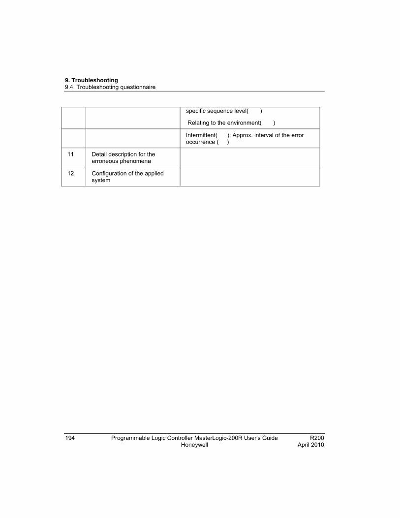
9. Troubleshooting 9.4. Troubleshooting questionnaire
194 Programmable Logic Controller MasterLogic-200R User's Guide R200 Honeywell April 2010
specific sequence level( )
Relating to the environment( )
Intermittent( ): Approx. interval of the error occurrence ( )
11 Detail description for the erroneous phenomena
12 Configuration of the applied system
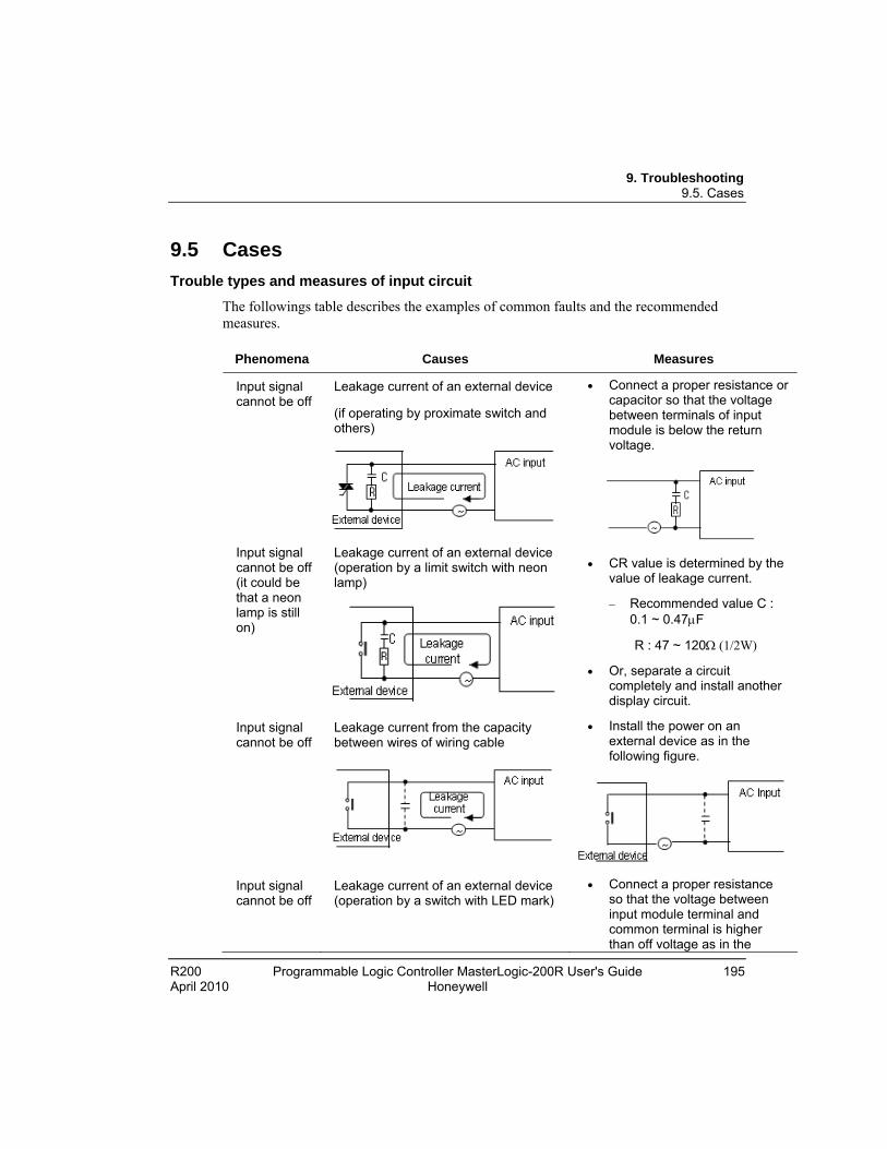
9. Troubleshooting 9.5. Cases
R200 Programmable Logic Controller MasterLogic-200R User's Guide 195 April 2010 Honeywell
9.5 Cases
Trouble types and measures of input circuit
The followings table describes the examples of common faults and the recommended measures.
Phenomena Causes Measures
Input signal cannot be off
Leakage current of an external device
(if operating by proximate switch and others)
Input signal cannot be off (it could be that a neon lamp is still on)
Leakage current of an external device (operation by a limit switch with neon lamp)
Connect a proper resistance or capacitor so that the voltage between terminals of input module is below the return voltage.
CR value is determined by the value of leakage current.
Recommended value C : 0.1 ~ 0.47F
R : 47 ~ 120 (1/2W)
Or, separate a circuit completely and install another display circuit.
Input signal cannot be off
Leakage current from the capacity between wires of wiring cable
Install the power on an external device as in the following figure.
Input signal cannot be off
Leakage current of an external device (operation by a switch with LED mark)
Connect a proper resistance so that the voltage between input module terminal and common terminal is higher than off voltage as in the
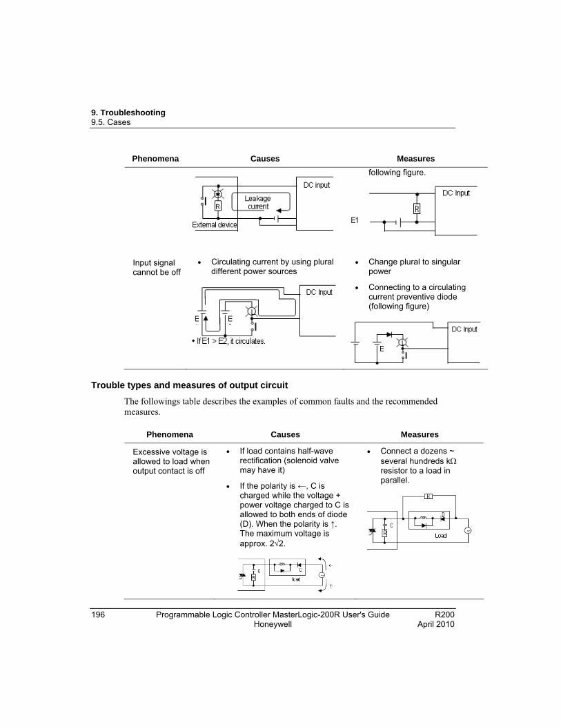
9. Troubleshooting 9.5. Cases
196 Programmable Logic Controller MasterLogic-200R User's Guide R200 Honeywell April 2010
Phenomena Causes Measures
following figure.
Input signal cannot be off
Circulating current by using plural different power sources
Change plural to singular power
Connecting to a circulating current preventive diode (following figure)
Trouble types and measures of output circuit
The followings table describes the examples of common faults and the recommended measures.
Phenomena Causes Measures
Excessive voltage is allowed to load when output contact is off
If load contains half-wave rectification (solenoid valve may have it)
If the polarity is ←, C is charged while the voltage + power voltage charged to C is allowed to both ends of diode (D). When the polarity is ↑. The maximum voltage is approx. 22.
Connect a dozens ~ several hundreds k resistor to a load in parallel.

9. Troubleshooting 9.5. Cases
R200 Programmable Logic Controller MasterLogic-200R User's Guide 197 April 2010 Honeywell
Phenomena Causes Measures
Note: when using it as the above, the output element does not have any problem but the performance of diode (D) in load may be reduced, probably causing a trouble.
Load cannot be off Leakage current from surge absorbing circuit connected to an output element in parallel.
Connect a dozen of k resistor or C-R of which impedance is equal to the resistance to load in parallel. Note: If the length of wiring from output module to load is long, it may have leakage current from capacity of cables.
Abnormal time when load is a C-R type timer
Leakage current from surge absorbing circuit connected to an output element in parallel.
Operate the C-R type timer by mediating a relay.
Use other one but a C-R type timer.
Note: A timer’s internal circuit may have half-wave rectification.
Load can not be off (DC)
Circulating current resulting from two different power source
Adjusting plural to singular power source.
Connecting to circulating current preventive diode (figure below)

9. Troubleshooting 9.5. Cases
198 Programmable Logic Controller MasterLogic-200R User's Guide R200 Honeywell April 2010
Phenomena Causes Measures
It circulates if E1< E2.
It also circulates even when E1 is Off (E2 is On).
Off response from load takes a longer time
Over current at Off
If a large current load such as solenoid (time constant L/R is large) is directly operated by transistor output.
Since current is allowed through diode when transistor output is off, it may be delayed for 1s and longer depending on load.
Insert a magnetic connector and others of which time constant is small as presented in the figure and operate load by the contact
Output transistor is destructed
Inrush current of glow lamp
As soon as it lights up, it may have 10 times and higher inrush current.
To restrict inrush current, it should allow dark current that is 1/3 ~ 1/5 of the rated current of glow lamp.
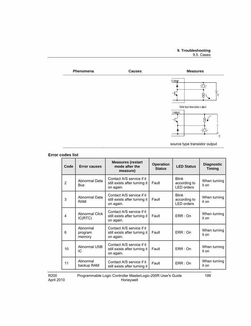
9. Troubleshooting 9.5. Cases
R200 Programmable Logic Controller MasterLogic-200R User's Guide 199 April 2010 Honeywell
Phenomena Causes Measures
source type transistor output
Error codes list
Code Error causes Measures (restart
mode after the measure)
Operation Status
LED Status Diagnostic
Timing
2 Abnormal Data Bus
Contact A/S service if it still exists after turning it on again.
Fault Blink according to LED orders
When turning it on
3 Abnormal Data RAM
Contact A/S service if it still exists after turning it on again.
Fault Blink according to LED orders
When turning it on
4 Abnormal Click IC(RTC)
Contact A/S service if it still exists after turning it on again.
Fault ERR : On When turning it on
6 Abnormal program memory
Contact A/S service if it still exists after turning it on again.
Fault ERR : On When turning it on
10 Abnormal USB IC
Contact A/S service if it still exists after turning it on again.
Fault ERR : On When turning it on
11 Abnormal backup RAM
Contact A/S service if it still exists after turning it
Fault ERR : On When turning it on
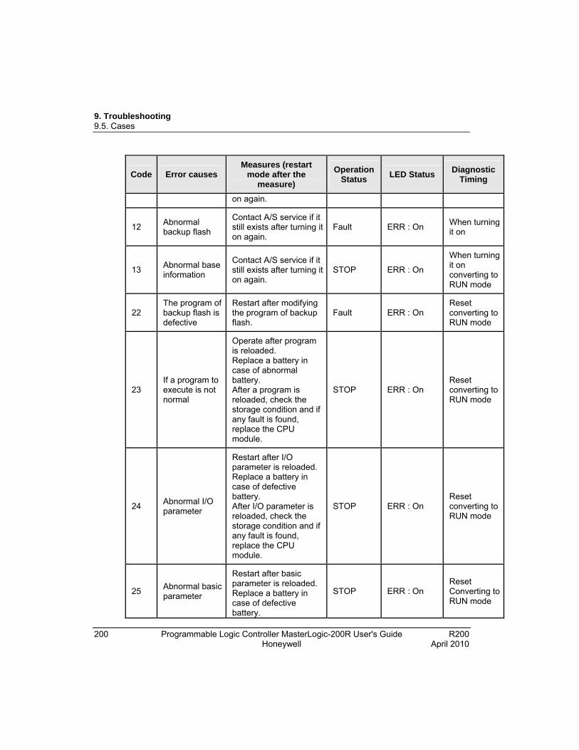
9. Troubleshooting 9.5. Cases
200 Programmable Logic Controller MasterLogic-200R User's Guide R200 Honeywell April 2010
Code Error causes Measures (restart
mode after the measure)
Operation Status
LED Status Diagnostic
Timing
on again.
12 Abnormal backup flash
Contact A/S service if it still exists after turning it on again.
Fault ERR : On When turning it on
13 Abnormal base information
Contact A/S service if it still exists after turning it on again.
STOP ERR : On
When turning it on converting to RUN mode
22 The program of backup flash is defective
Restart after modifying the program of backup flash.
Fault ERR : On Reset converting to RUN mode
23 If a program to execute is not normal
Operate after program is reloaded. Replace a battery in case of abnormal battery. After a program is reloaded, check the storage condition and if any fault is found, replace the CPU module.
STOP ERR : On Reset converting to RUN mode
24 Abnormal I/O parameter
Restart after I/O parameter is reloaded. Replace a battery in case of defective battery. After I/O parameter is reloaded, check the storage condition and if any fault is found, replace the CPU module.
STOP ERR : On Reset converting to RUN mode
25 Abnormal basic parameter
Restart after basic parameter is reloaded. Replace a battery in case of defective battery.
STOP ERR : On Reset Converting to RUN mode

9. Troubleshooting 9.5. Cases
R200 Programmable Logic Controller MasterLogic-200R User's Guide 201 April 2010 Honeywell
Code Error causes Measures (restart
mode after the measure)
Operation Status
LED Status Diagnostic
Timing
After basic parameter is reloaded, check the storage condition and if any fault is found, replace the CPU module.
30
The module set in parameter and the actually installed module do not coincide
Check the wrong slot position by SoftMaster, modify a module or parameter and then, restart.
Reference flag: module type inconsistence error flag.
STOP (RUN)
ERR : On (P.S. : On)
Converting to RUN mode
31
Module detachment or module addition during operation
Check any detached/added slot position by SoftMaster, modify the installment and restart (according to parameter). Reference flag: module attachment error flag.
STOP (RUN)
ERR : On (P.S. : On)
When scan ends
32
Fuse of a module holding a fuse is burnt out during operation
Check the position of a slot of which fuse is burnt out by SoftMaster, replace a fuse and restart (according to parameter). Reference flag: fuse disconnection error flag
STOP (RUN)
ERR : On (P.S. : On)
When scan ends
33
IO module data cannot be successfully accessed during operation
Check the position of a slot with access error by SoftMaster, replace the module and restart (according to parameter) Reference flag: I/O Module Write/Read error flag
STOP (RUN)
ERR : On (P.S. : On)
When scan ends
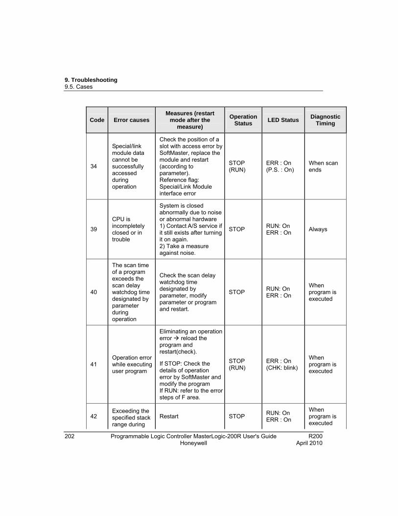
9. Troubleshooting 9.5. Cases
202 Programmable Logic Controller MasterLogic-200R User's Guide R200 Honeywell April 2010
Code Error causes Measures (restart
mode after the measure)
Operation Status
LED Status Diagnostic
Timing
34
Special/link module data cannot be successfully accessed during operation
Check the position of a slot with access error by SoftMaster, replace the module and restart (according to parameter). Reference flag: Special/Link Module interface error
STOP (RUN)
ERR : On (P.S. : On)
When scan ends
39
CPU is incompletely closed or in trouble
System is closed abnormally due to noise or abnormal hardware 1) Contact A/S service if it still exists after turning it on again. 2) Take a measure against noise.
STOP RUN: On ERR : On
Always
40
The scan time of a program exceeds the scan delay watchdog time designated by parameter during operation
Check the scan delay watchdog time designated by parameter, modify parameter or program and restart.
STOP RUN: On ERR : On
When program is executed
41 Operation error while executing user program
Eliminating an operation error reload the program and restart(check).
If STOP: Check the details of operation error by SoftMaster and modify the program If RUN: refer to the error steps of F area.
STOP (RUN)
ERR : On (CHK: blink)
When program is executed
42 Exceeding the specified stack range during
Restart STOP RUN: On ERR : On
When program is executed
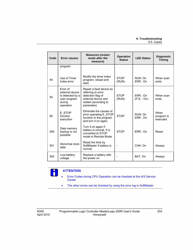
9. Troubleshooting 9.5. Cases
R200 Programmable Logic Controller MasterLogic-200R User's Guide 203 April 2010 Honeywell
Code Error causes Measures (restart
mode after the measure)
Operation Status
LED Status Diagnostic
Timing
program
44 Use of Timer Index error
Modify the timer index program, reload and start.
STOP (RUN)
RUN: On ERR : On
When scan ends
50
Error of external device is detected by a user program during operation
Repair a fault device by referring to error detection flag of external device and restart (according to parameter)
STOP (RUN)
ERR : On (P.S. : On)
When scan ends
60 E_STOP function execution
Eliminate the causes of error operating E_STOP function in the program and turn it on again.
STOP RUN: On ERR : On
When program is executed
500 Data memory backup is not possible
Turn it on again if battery is normal. It is converted to STOP mode in Remote Mode.
STOP ERR : On Reset
501 Abnormal clock data
Reset the time by SoftMaster if battery is normal.
- CHK: On Always
502 Low-battery voltage
Replace a battery with the power on
- BAT: On Always
ATTENTION
Error Codes during CPU Operation can be checked at the A/S Service Center.
The other errors can be checked by using the error log in SoftMaster.

9. Troubleshooting 9.5. Cases
204 Programmable Logic Controller MasterLogic-200R User's Guide R200 Honeywell April 2010
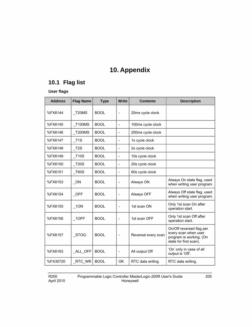
R200 Programmable Logic Controller MasterLogic-200R User's Guide 205 April 2010 Honeywell
10. Appendix
10.1 Flag list
User flags
Address Flag Name Type Write Contents Description
%FX6144 _T20MS BOOL - 20ms cycle clock
%FX6145 _T100MS BOOL - 100ms cycle clock
%FX6146 _T200MS BOOL - 200ms cycle clock
%FX6147 _T1S BOOL - 1s cycle clock
%FX6148 _T2S BOOL - 2s cycle clock
%FX6149 _T10S BOOL - 10s cycle clock
%FX6150 _T20S BOOL - 20s cycle clock
%FX6151 _T60S BOOL - 60s cycle clock
%FX6153 _ON BOOL - Always ON Always On state flag, used when writing user program.
%FX6154 _OFF BOOL - Always OFF Always Off state flag, used when writing user program.
%FX6155 _1ON BOOL - 1st scan ON Only 1st scan On after operation start.
%FX6156 _1OFF BOOL - 1st scan OFF Only 1st scan Off after operation start.
%FX6157 _STOG BOOL - Reversal every scan
On/Off reversed flag per every scan when user program is working. (On state for first scan).
%FX6163 _ALL_OFF BOOL - All output Off ‘On’ only in case of all output is ‘Off’.
%FX30720 _RTC_WR BOOL OK RTC data writing RTC data writing.
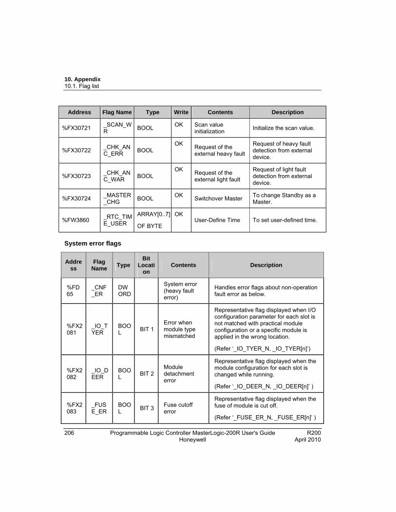
10. Appendix 10.1. Flag list
206 Programmable Logic Controller MasterLogic-200R User's Guide R200 Honeywell April 2010
Address Flag Name Type Write Contents Description
%FX30721 _SCAN_WR
BOOL OK Scan value
initialization Initialize the scan value.
%FX30722 _CHK_ANC_ERR
BOOL OK
Request of the external heavy fault
Request of heavy fault detection from external device.
%FX30723 _CHK_ANC_WAR
BOOL OK
Request of the external light fault
Request of light fault detection from external device.
%FX30724 _MASTER_CHG
BOOL OK
Switchover Master To change Standby as a Master.
%FW3860 _RTC_TIME_USER
ARRAY[0..7]
OF BYTE
OK User-Define Time To set user-defined time.
System error flags
Address
Flag Name
Type Bit
Location
Contents Description
%FD65
_CNF_ER
DWORD
System error (heavy fault error)
Handles error flags about non-operation fault error as below.
%FX2081
_IO_TYER
BOOL
BIT 1 Error when module type mismatched
Representative flag displayed when I/O configuration parameter for each slot is not matched with practical module configuration or a specific module is applied in the wrong location.
(Refer ‘_IO_TYER_N, _IO_TYER[n]’)
%FX2082
_IO_DEER
BOOL
BIT 2 Module detachment error
Representative flag displayed when the module configuration for each slot is changed while running.
(Refer ‘_IO_DEER_N, _IO_DEER[n]’ )
%FX2083
_FUSE_ER
BOOL
BIT 3 Fuse cutoff error
Representative flag displayed when the fuse of module is cut off.
(Refer ‘_FUSE_ER_N, _FUSE_ER[n]’ )

10. Appendix 10.1. Flag list
R200 Programmable Logic Controller MasterLogic-200R User's Guide 207 April 2010 Honeywell
Address
Flag Name
Type Bit
Location
Contents Description
%FX2086
_ANNUM_ER
BOOL
BIT 6
Heavy fault detection error in external device
Representative flag displayed when heavy fault error detected by user program is recorded in ‘_ANC_ERR[n]’.
%FX2088
_BPRM_ER
BOOL
BIT 8 Basic parameter error
It is abnormal to the basic parameter.
%FX2089
_IOPRM_ER
BOOL
BIT 9 I/O parameter error
It is abnormal to the I/O configuration parameter.
%FX2090
_SPPRM_ER
BOOL
BIT 10
Special module parameter error
It is abnormal to the special module parameter.
%FX2091
_CPPRM_ER
BOOL
BIT 11
Communication module parameter error
It is abnormal to the communication module parameter.
%FX2092
_PGM_ER
BOOL
BIT 12
Program error Indicates that there is problem with user-made program checksum.
%FX2093
_CODE_ER
BOOL
BIT 13
Program code error
Indicates that while user program is running, the program code cannot be interpreted.
%FX2094
_SWDT_ER
BOOL
BIT 14
CPU abnormal ends
Displayed when the saved program gets damages by an abnormal end of CPU or program cannot work.
%FX2095
_BASE_POWER_ER
BOOL
BIT 15
Power error Indicates that base power is abnormal.
%FX2096
_WDT_ER
BOOL
BIT 16
Scan watchdog error
Indicates that the program scan time exceeds the scan watchdog time specified by a parameter.
%FX2097
_BASE_INFO_ER
BOOL
BIT 17
Wrong base information
Wrong information for main base.
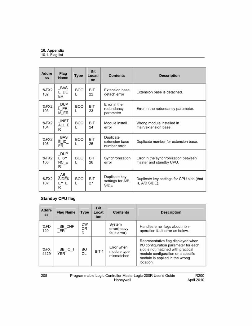
10. Appendix 10.1. Flag list
208 Programmable Logic Controller MasterLogic-200R User's Guide R200 Honeywell April 2010
Address
Flag Name
Type Bit
Location
Contents Description
%FX2102
_BASE_DEER
BOOL
BIT 22
Extension base detach error
Extension base is detached.
%FX2103
_DUPL_PRM_ER
BOOL
BIT 23
Error in the redundancy parameter
Error in the redundancy parameter.
%FX2104
_INSTALL_ER
BOOL
BIT 24
Module install error
Wrong module installed in main/extension base.
%FX2105
_BASE_ID_ER
BOOL
BIT 25
Duplicate extension base number error
Duplicate number for extension base.
%FX2106
_DUPL_SYNC_ER
BOOL
BIT 26
Synchronization error
Error in the synchronization between master and standby CPU.
%FX2107
_AB_SIDEKEY_ER
BOOL
BIT 27
Duplicate key settings for A/B SIDE
Duplicate key settings for CPU side (that is, A/B SIDE).
Standby CPU flag
Address
Flag Name Type Bit
Location
Contents Description
%FD129
_SB_CNF_ER
DWORD
System error(heavy fault error)
Handles error flags about non-operation fault error as below.
%FX4129
_SB_IO_TYER
BOOL
BIT 1Error when module type mismatched
Representative flag displayed when I/O configuration parameter for each slot is not matched with practical module configuration or a specific module is applied in the wrong location.

10. Appendix 10.1. Flag list
R200 Programmable Logic Controller MasterLogic-200R User's Guide 209 April 2010 Honeywell
Address
Flag Name Type Bit
Location
Contents Description
(Refer ‘_IO_TYER_N, _IO_TYER[n]’ )
%FX4130
_SB_IO_DEER
BOOL
BIT 2Module detachment error
Representative flag displayed when the module configuration for each slot is changed while running.
(Refer ‘_IO_DEER_N, _IO_DEER[n]’ )
%FX4131
_SB_FUSE_ER
BOOL
BIT 3Fuse cutoff error
Representative flag displayed when the fuse of module is cut off.
(Refer ‘_FUSE_ER_N, _FUSE_ER[n]’ )
%FX4134
_SB_ANNUM_ER
BOOL
BIT 6
Heavy fault detection error in external device
Representative flag displayed when heavy fault error detected by user program is recorded in ‘_ANC_ERR[n]’.
%FX4136
_SB_BPRM_ER
BOOL
BIT 8Basic parameter error
It is abnormal to the basic parameter.
%FX4137
_SB_IOPRM_ER
BOOL
BIT 9I/O parameter error
It is abnormal to the I/O configuration parameter.
%FX4138
_SB_SPPRM_ER
BOOL BIT
10
Special module parameter error
It is abnormal to the special module parameter.
%FX4139
_SB_CPPRM_ER
BOOL BIT
11
Communication module parameter error
It is abnormal to the communication module parameter.
%FX4141
_SB_CODE_ER
BOOL
BIT 13
Program error Indicates that there is problem with user-made program checksum.
%FX4142
_SB_SWDT_ER
BOOL
BIT 14
CPU abnormal ends.
Displayed when the saved program gets damaged by an abnormal end of

10. Appendix 10.1. Flag list
210 Programmable Logic Controller MasterLogic-200R User's Guide R200 Honeywell April 2010
Address
Flag Name Type Bit
Location
Contents Description
CPU or program cannot work.
%FX4143
_SB_BASE_POWER_ER
BOOL
BIT 15
Power error Indicates that base power is abnormal.
%FX4144
_SB_WDT_ER
BOOL
BIT 16
Scan watchdog error
Indicates that the program scan time exceeds the scan watchdog time specified by a parameter.
%FX4145
_SB_BASE_INFO_ER
BOOL
BIT 17
Base information error
Wrong base information.
%FX4150
_SB_BASE_DEER
BOOL
BIT 22
Extension base detach error
Extension base is detached.
%FX4151
_SB_DUPL_PRM_ER
BOOL
BIT 23
Error in the redundancy parameter
Error in the redundancy parameter.
%FX4152
_SB_INSTALL_ER
BOOL
BIT 24
Module install error
Wrong module installed in main/extension base.
%FX4153
_SB_BASE_ID_ER
BOOL
BIT 25
Duplicate extension base number error
Duplicate number for extension base.
%FX4154
_SB_DUPL_SYNC_ER
BOOL
BIT 26
Synchronization error
Error in the synchronization between master and standby CPU.
%FX4156
_SB_CPU_RUN_ER
BOOL
BIT 28
Standby CPU run error
Standby CPU fails to operate in redundancy mode when master CPU fails.
Master CPU error flags
Address
Flag Name Type Write
Contents Description
%FW _IO_TYERARRAY[0..31] OF
- Error when Module type
Representative flag displayed when I/O configuration parameter for each
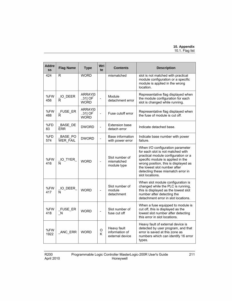
10. Appendix 10.1. Flag list
R200 Programmable Logic Controller MasterLogic-200R User's Guide 211 April 2010 Honeywell
Address
Flag Name Type Write
Contents Description
424 R WORD mismatched slot is not matched with practical module configuration or a specific module is applied in the wrong location.
%FW456
_IO_DEERR
ARRAY[0..31] OF WORD
- Module detachment error
Representative flag displayed when the module configuration for each slot is changed while running.
%FW488
_FUSE_ERR
ARRAY[0..31] OF WORD
- Fuse cutoff error Representative flag displayed when the fuse of module is cut off.
%FD83
_BASE_DEERR
DWORD - Extension base detach error
Indicate detached base.
%FD574
_BASE_POWER_FAIL
DWORD - Base information with power error
Indicate base number with power failure.
%FW416
_IO_TYER_N
WORD - Slot number of mismatched module type
When I/O configuration parameter for each slot is not matched with practical module configuration or a specific module is applied in the wrong position, this is displayed as the lowest slot number after detecting these mismatch error in slot locations.
%FW417
_IO_DEER_N
WORD - Slot number of module detachment
When slot module configuration is changed while the PLC is running, this is displayed as the lowest slot number after detecting the detachment error in slot locations.
%FW418
_FUSE_ER_N
WORD - Slot number of fuse cut off
When a fuse equipped to module is cut off, this is displayed as the lowest slot number after detecting this error in slot locations.
%FW1922
_ANC_ERR WORD OK
Heavy fault information of external device
Heavy fault of external device is detected by user program, and that error is saved at this zone as numbers which can identify 16 error types.
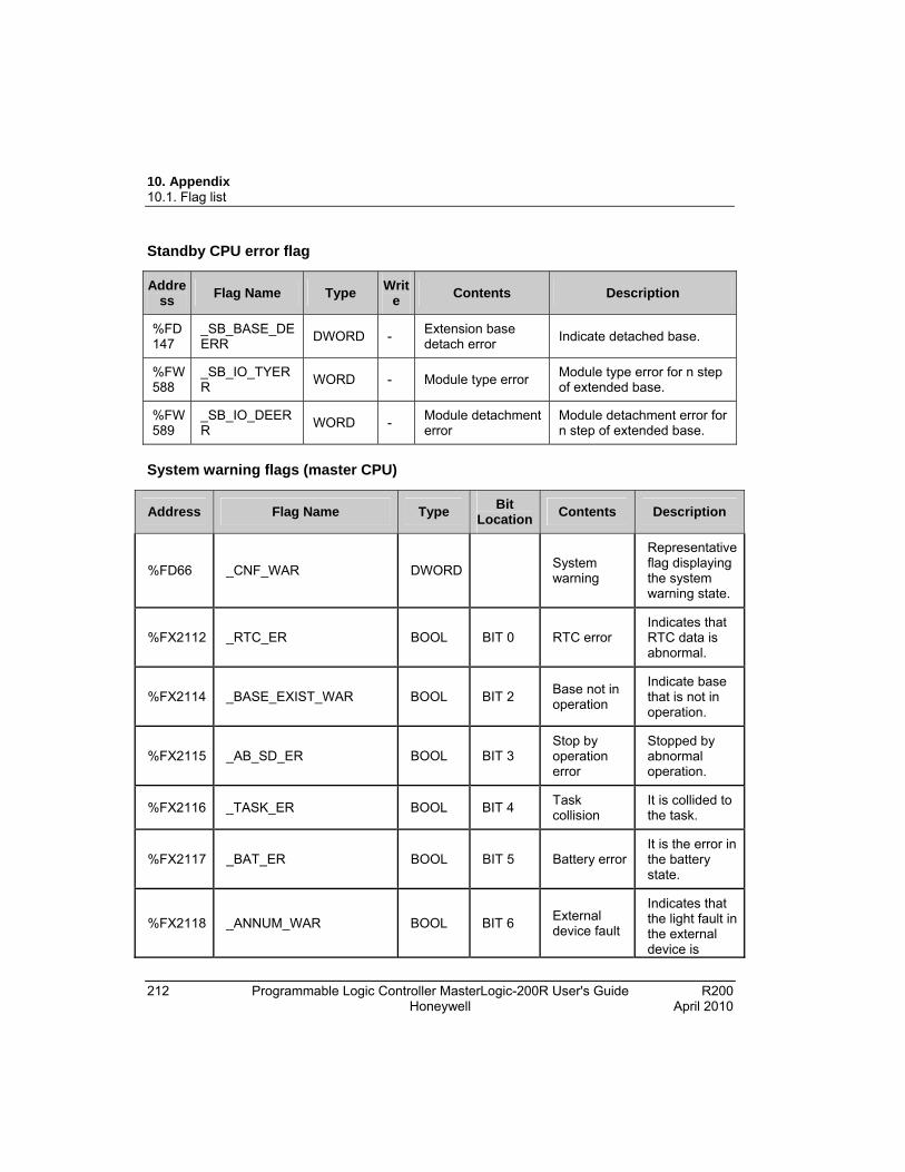
10. Appendix 10.1. Flag list
212 Programmable Logic Controller MasterLogic-200R User's Guide R200 Honeywell April 2010
Standby CPU error flag
Address
Flag Name Type Writ
e Contents Description
%FD147
_SB_BASE_DEERR
DWORD - Extension base detach error
Indicate detached base.
%FW588
_SB_IO_TYERR
WORD - Module type error Module type error for n step of extended base.
%FW589
_SB_IO_DEERR
WORD - Module detachment error
Module detachment error for n step of extended base.
System warning flags (master CPU)
Address Flag Name Type Bit
LocationContents Description
%FD66 _CNF_WAR DWORD System warning
Representative flag displaying the system warning state.
%FX2112 _RTC_ER BOOL BIT 0 RTC error Indicates that RTC data is abnormal.
%FX2114 _BASE_EXIST_WAR BOOL BIT 2 Base not in operation
Indicate base that is not in operation.
%FX2115 _AB_SD_ER BOOL BIT 3 Stop by operation error
Stopped by abnormal operation.
%FX2116 _TASK_ER BOOL BIT 4 Task collision
It is collided to the task.
%FX2117 _BAT_ER BOOL BIT 5 Battery error It is the error in the battery state.
%FX2118 _ANNUM_WAR BOOL BIT 6 External device fault
Indicates that the light fault in the external device is

10. Appendix 10.1. Flag list
R200 Programmable Logic Controller MasterLogic-200R User's Guide 213 April 2010 Honeywell
Address Flag Name Type Bit
LocationContents Description
detected.
%FX2120 _HS_WAR
BOOL BIT 8
High-speed link parameter error
It is abnormal to the high-speed link parameter.
%FX2121 _REDUN_WAR BOOL BIT 9 Redundancy configuration warning
System is not in redundancy mode (not in Single CPU mode).
%FX2122 _OS_VER_WAR BOOL BIT 10 Warning for O/S version mismatch
OS version between CPU, Network, and Extension Driver is different.
%FX2123 _RING_WAR BOOL BIT 11 Warning for ring topology
Ring Topology is not established.
%FX2132 _P2P_WAR BOOL BIT 20
P2P parameter error
It is abnormal to the P2P parameter.
%FX2140 _CONSTANT_ER BOOL BIT 28 Fixed cycle fault
Fixed cycle fault.
%FX2141 _BASE_POWER_WAR BOOL BIT 29 Abnormal power module
One of the two power modules has an error or turned off.
%FX2142 _BASE_SKIP_WAR BOOL BIT 30 Base skip warning
When base skip is disabled, IO parameter and hardware configuration is different.
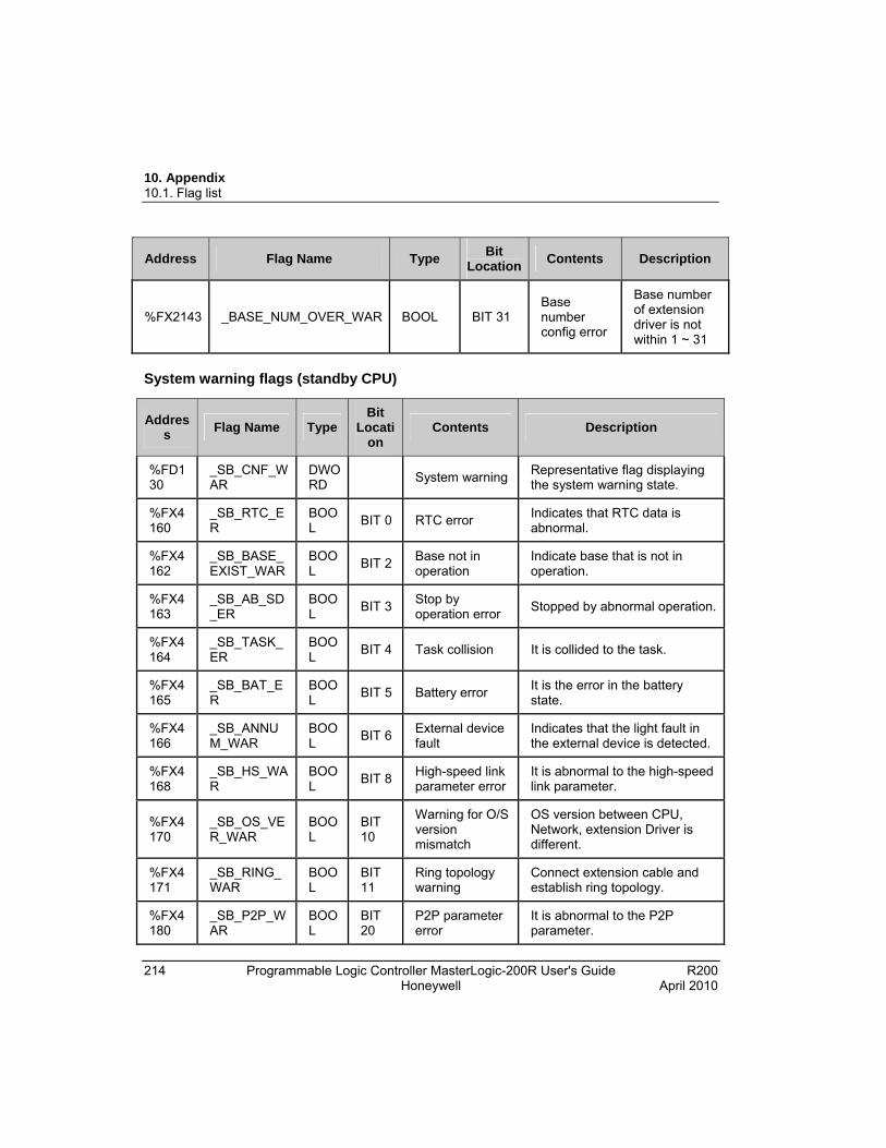
10. Appendix 10.1. Flag list
214 Programmable Logic Controller MasterLogic-200R User's Guide R200 Honeywell April 2010
Address Flag Name Type Bit
LocationContents Description
%FX2143 _BASE_NUM_OVER_WAR BOOL BIT 31 Base number config error
Base number of extension driver is not within 1 ~ 31
System warning flags (standby CPU)
Address
Flag Name Type Bit
Location
Contents Description
%FD130
_SB_CNF_WAR
DWORD
System warning Representative flag displaying the system warning state.
%FX4160
_SB_RTC_ER
BOOL
BIT 0 RTC error Indicates that RTC data is abnormal.
%FX4162
_SB_BASE_EXIST_WAR
BOOL
BIT 2 Base not in operation
Indicate base that is not in operation.
%FX4163
_SB_AB_SD_ER
BOOL
BIT 3 Stop by operation error
Stopped by abnormal operation.
%FX4164
_SB_TASK_ER
BOOL
BIT 4 Task collision It is collided to the task.
%FX4165
_SB_BAT_ER
BOOL
BIT 5 Battery error It is the error in the battery state.
%FX4166
_SB_ANNUM_WAR
BOOL
BIT 6 External device fault
Indicates that the light fault in the external device is detected.
%FX4168
_SB_HS_WAR
BOOL
BIT 8 High-speed link parameter error
It is abnormal to the high-speed link parameter.
%FX4170
_SB_OS_VER_WAR
BOOL
BIT 10
Warning for O/S version mismatch
OS version between CPU, Network, extension Driver is different.
%FX4171
_SB_RING_WAR
BOOL
BIT 11
Ring topology warning
Connect extension cable and establish ring topology.
%FX4180
_SB_P2P_WAR
BOOL
BIT 20
P2P parameter error
It is abnormal to the P2P parameter.

10. Appendix 10.1. Flag list
R200 Programmable Logic Controller MasterLogic-200R User's Guide 215 April 2010 Honeywell
Address
Flag Name Type Bit
Location
Contents Description
%FX4188
_SB_CONSTANT_ER
BOOL
BIT 28
Fixed cycle fault Fixed cycle fault.
%FX4189
_SB_BASE_POWER_WAR
BOOL
BIT 29
Warning for ring topology
Ring topology is not established.
%FX4190
_SB_BASE_SKIP_WAR
BOOL
BIT 30
Base skip warning
When base skip is disabled, IO parameter and hardware configuration is different.
%FX4191
_SB_BASE_NUM_OVER_WAR
BOOL
BIT 31
Base number config error
Base number of extension driver is not within 1 ~ 31.
Communication warning flags (Master CPU)
Address
Flag Name
Type Write Contents Description
%FX2624
_HS_WARN
ARRAY[0..11] OF BOOL
- High-speed link parameter error
It is abnormal to the high-speed link parameter n (n: 1~12).
%FX2640
_P2P_WARN
ARRAY[0..7] OF BOOL
- P2P parameter errorIt is abnormal to the P2P parameter n (n: 1~8).
%FD587
_BASE_ACPF_WAR
DWORD - Momentary power loss warning
Indicate base with momentary power loss.
%FW164
_HS_WAR_W
WORD -
High-speed link parameter error
It is abnormal to the high-speed link parameter n (n: 1~12).
%FW165
_P2P_WAR_W WORD
- P2P parameter errorIt is abnormal to the P2P parameter n (n: 1~8).
%FW1923
_ANC_WAR
WORD - Heavy fault information of external device
Heavy fault of external device is detected by user program, and that error is saved at this zone as numbers which can identify
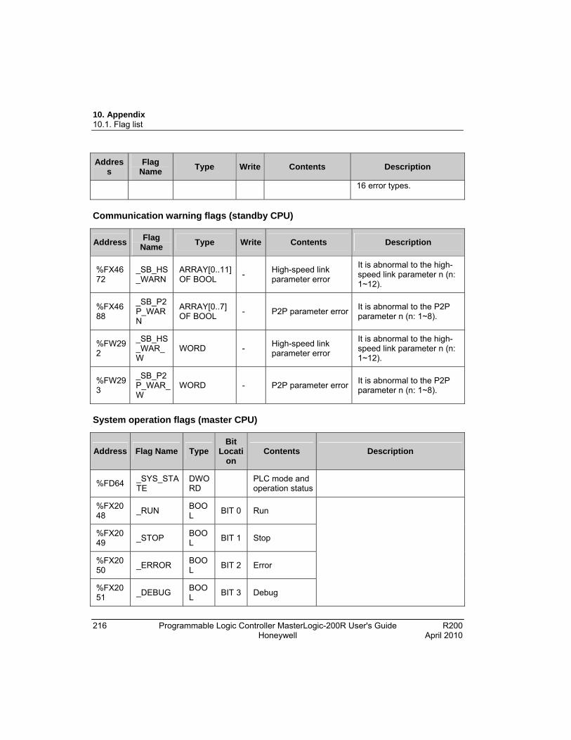
10. Appendix 10.1. Flag list
216 Programmable Logic Controller MasterLogic-200R User's Guide R200 Honeywell April 2010
Address
Flag Name
Type Write Contents Description
16 error types.
Communication warning flags (standby CPU)
Address Flag
Name Type Write Contents Description
%FX4672
_SB_HS_WARN
ARRAY[0..11] OF BOOL
- High-speed link parameter error
It is abnormal to the high-speed link parameter n (n: 1~12).
%FX4688
_SB_P2P_WARN
ARRAY[0..7] OF BOOL
- P2P parameter errorIt is abnormal to the P2P parameter n (n: 1~8).
%FW292
_SB_HS_WAR_W
WORD - High-speed link parameter error
It is abnormal to the high- speed link parameter n (n: 1~12).
%FW293
_SB_P2P_WAR_W
WORD - P2P parameter errorIt is abnormal to the P2P parameter n (n: 1~8).
System operation flags (master CPU)
Address Flag Name Type Bit
Location
Contents Description
%FD64 _SYS_STATE
DWORD
PLC mode and operation status
%FX2048
_RUN BOOL
BIT 0 Run
%FX2049
_STOP BOOL
BIT 1 Stop
%FX2050
_ERROR BOOL
BIT 2 Error
%FX2051
_DEBUG BOOL
BIT 3 Debug
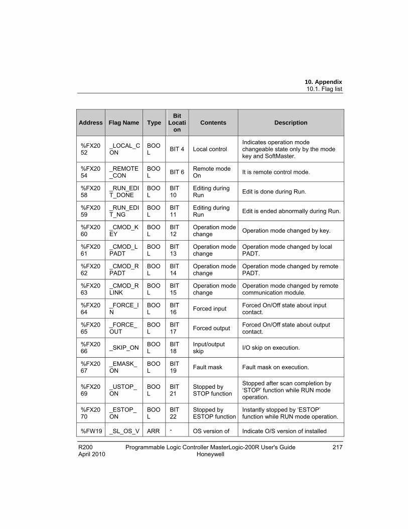
10. Appendix 10.1. Flag list
R200 Programmable Logic Controller MasterLogic-200R User's Guide 217 April 2010 Honeywell
Address Flag Name Type Bit
Location
Contents Description
%FX2052
_LOCAL_CON
BOOL
BIT 4 Local control Indicates operation mode changeable state only by the mode key and SoftMaster.
%FX2054
_REMOTE_CON
BOOL
BIT 6 Remote mode On
It is remote control mode.
%FX2058
_RUN_EDIT_DONE
BOOL
BIT 10
Editing during Run
Edit is done during Run.
%FX2059
_RUN_EDIT_NG
BOOL
BIT 11
Editing during Run
Edit is ended abnormally during Run.
%FX2060
_CMOD_KEY
BOOL
BIT 12
Operation mode change
Operation mode changed by key.
%FX2061
_CMOD_LPADT
BOOL
BIT 13
Operation mode change
Operation mode changed by local PADT.
%FX2062
_CMOD_RPADT
BOOL
BIT 14
Operation mode change
Operation mode changed by remote PADT.
%FX2063
_CMOD_RLINK
BOOL
BIT 15
Operation mode change
Operation mode changed by remote communication module.
%FX2064
_FORCE_IN
BOOL
BIT 16
Forced input Forced On/Off state about input contact.
%FX2065
_FORCE_OUT
BOOL
BIT 17
Forced output Forced On/Off state about output contact.
%FX2066
_SKIP_ON BOOL
BIT 18
Input/output skip
I/O skip on execution.
%FX2067
_EMASK_ON
BOOL
BIT 19
Fault mask Fault mask on execution.
%FX2069
_USTOP_ON
BOOL
BIT 21
Stopped by STOP function
Stopped after scan completion by ‘STOP’ function while RUN mode operation.
%FX2070
_ESTOP_ON
BOOL
BIT 22
Stopped by ESTOP function
Instantly stopped by ‘ESTOP’ function while RUN mode operation.
%FW19 _SL_OS_V ARR - OS version of Indicate O/S version of installed
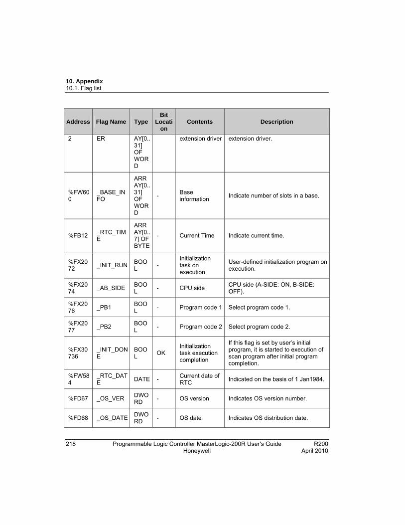
10. Appendix 10.1. Flag list
218 Programmable Logic Controller MasterLogic-200R User's Guide R200 Honeywell April 2010
Address Flag Name Type Bit
Location
Contents Description
2 ER AY[0..31] OF WORD
extension driver extension driver.
%FW600
_BASE_INFO
ARRAY[0..31] OF WORD
- Base information
Indicate number of slots in a base.
%FB12 _RTC_TIME
ARRAY[0..7] OF BYTE
- Current Time Indicate current time.
%FX2072
_INIT_RUN BOOL
- Initialization task on execution
User-defined initialization program on execution.
%FX2074
_AB_SIDE BOOL
- CPU side CPU side (A-SIDE: ON, B-SIDE: OFF).
%FX2076
_PB1 BOOL
- Program code 1 Select program code 1.
%FX2077
_PB2 BOOL
- Program code 2 Select program code 2.
%FX30736
_INIT_DONE
BOOL
OK Initialization task execution completion
If this flag is set by user’s initial program, it is started to execution of scan program after initial program completion.
%FW584
_RTC_DATE
DATE - Current date of RTC
Indicated on the basis of 1 Jan1984.
%FD67 _OS_VER DWORD
- OS version Indicates OS version number.
%FD68 _OS_DATE DWORD
- OS date Indicates OS distribution date.

10. Appendix 10.1. Flag list
R200 Programmable Logic Controller MasterLogic-200R User's Guide 219 April 2010 Honeywell
Address Flag Name Type Bit
Location
Contents Description
%FD69 _CP_OS_VER
DWORD
- OS version of extension manager
OS version of extension manager.
%FD573
_OS_TYPE DWORD
-
%FW1081
_FALS_NUM
INT - FALS no Indicates the number of False.
%FD293
_RTC_TOD
TIME_OF_DAY
- Current time of RTC (unit : ms )
Indicates a data for the time of the day on the basis of 00:00:00 (unit: ms).
%FD582
_RUN_EDIT_CNT
UDINT
- Online edit count
Online edit count.
%FW140
_AC_F_CNT
UINT - Indicates momentary shutdown times
Indicates the instant power off count during the RUN mode operation.
%FW158
_POWER_OFF_CNT
UINT - Power Off count Indicate no of power failure.
%FW386
_SCAN_MAX
UINT OK Maximum scan time
Indicates maximum scan time during operation
Unit: 0.1ms.
%FW387
_SCAN_MIN
UINT
OK Minimum scan time
Indicates minimum scan time during operation
Unit: 0.1ms.
%FW388
_SCAN_CUR
UINT
OK Current scan time
Indicates current scan time during operation
Unit: 0.1ms.
%FW585
_RTC_WEEK
UINT - Current day of the week of RTC
Indicates a day of the week.
(0: Mon. 1: Tue. 2: Wed. 3: Thu. 4: Fri. 5: Sat. 6: Sun).
%FW14 _CPU_TYP WOR - CPU Type Information.
Indicates the operation mode and
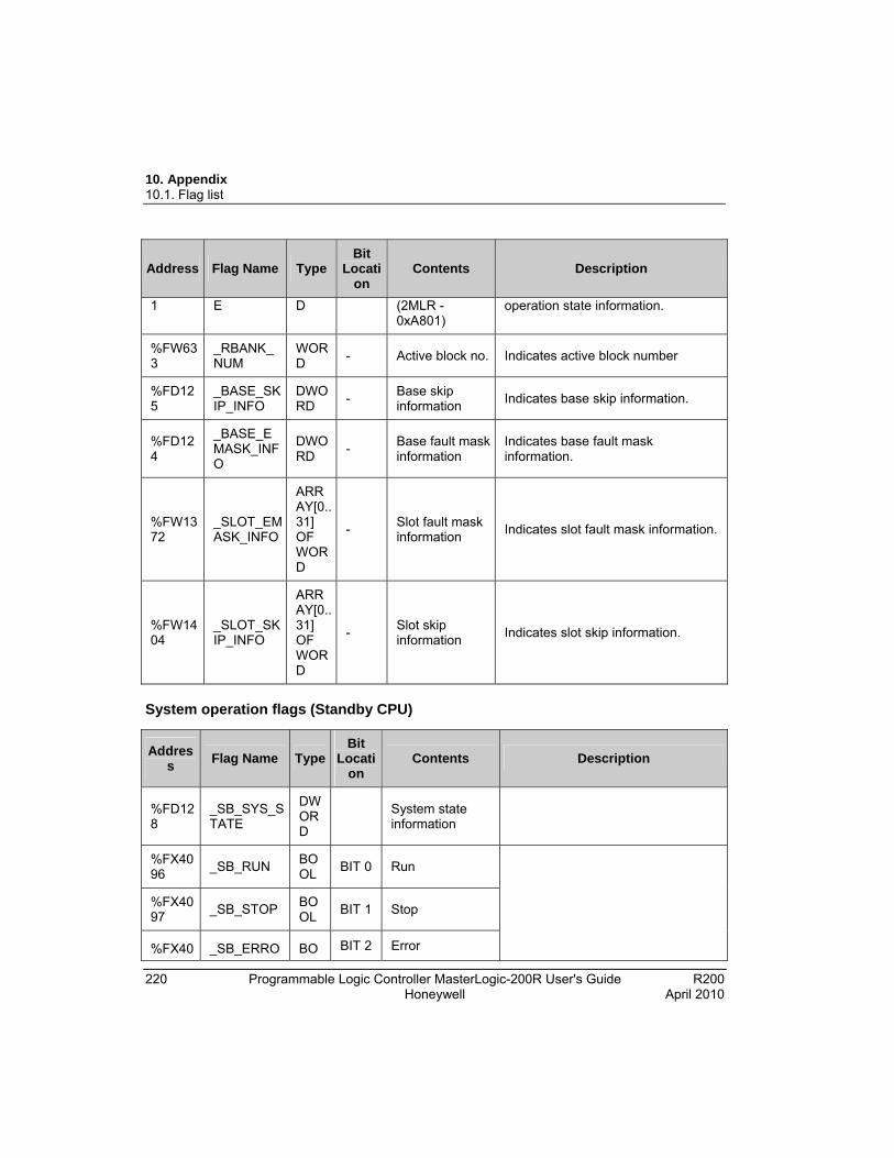
10. Appendix 10.1. Flag list
220 Programmable Logic Controller MasterLogic-200R User's Guide R200 Honeywell April 2010
Address Flag Name Type Bit
Location
Contents Description
1 E D (2MLR - 0xA801)
operation state information.
%FW633
_RBANK_NUM
WORD
- Active block no. Indicates active block number
%FD125
_BASE_SKIP_INFO
DWORD
- Base skip information
Indicates base skip information.
%FD124
_BASE_EMASK_INFO
DWORD
- Base fault mask information
Indicates base fault mask information.
%FW1372
_SLOT_EMASK_INFO
ARRAY[0..31] OF WORD
- Slot fault mask information
Indicates slot fault mask information.
%FW1404
_SLOT_SKIP_INFO
ARRAY[0..31] OF WORD
- Slot skip information
Indicates slot skip information.
System operation flags (Standby CPU)
Address
Flag Name Type Bit
Location
Contents Description
%FD128
_SB_SYS_STATE
DWORD
System state information
%FX4096
_SB_RUN BOOL
BIT 0 Run
%FX4097
_SB_STOP BOOL
BIT 1 Stop
%FX40 _SB_ERRO BO BIT 2 Error

10. Appendix 10.1. Flag list
R200 Programmable Logic Controller MasterLogic-200R User's Guide 221 April 2010 Honeywell
Address
Flag Name Type Bit
Location
Contents Description
98 R OL
%FX4100
_SB_LOCAL_CON
BOOL
BIT 4 Local control Local control.
%FX4102
_SB_REMOTE_CON
BOOL
BIT 6 Remote mode ON
Remote mode ON.
%FX4106
_SB_RUN_EDIT_DONE
BOOL
BIT 10
Editing during Run
Edit is done during Run.
%FX4107
_SB_RUN_EDIT_NG
BOOL
BIT 11
Editing during Run
Edit is ended abnormally during Run.
%FX4108
_SB_CMOD_KEY
BOOL
BIT 12
Operation mode change
Operation mode changed by key.
%FX4109
_SB_CMOD_LPADT
BOOL
BIT 13
Operation mode change
Operation mode changed by local PADT.
%FX4110
_SB_CMOD_RPADT
BOOL
BIT 14
Operation mode change
Operation mode changed by Remote PADT.
%FX4111
_SB_CMOD_RLINK
BOOL
BIT 15
Operation mode change
Operation mode changed by remote communication module.
%FX4112
_SB_FORCE_IN
BOOL
BIT 16
Forced Input Forced On/Off state about input contact.
%FX4113
_SB_FORCE_OUT
BOOL
BIT 17
Forced Output Forced On/Off state about output contact.
%FX4114
_SB_SKIP_ON
BOOL
BIT 18
Input/Output Skip I/O skip on execution.
%FX4115
_SB_EMASK_ON
BOOL
BIT 19
Fault mask Fault mask on execution.
%FX4117
_SB_USTOP_ON
BOOL
- Stopped by STOP function
Stopped after scan completion by ‘STOP’ function while RUN mode operation.
%FX4118
_SB_ESTOP_ON
BOOL
- Stopped by ESTOP function
Instantly stopped by ‘ESTOP’ function while RUN mode operation.

10. Appendix 10.1. Flag list
222 Programmable Logic Controller MasterLogic-200R User's Guide R200 Honeywell April 2010
Address
Flag Name Type Bit
Location
Contents Description
%FD131
_SB_OS_VER
DWORD
- OS version Indicates OS version number.
%FD132
_SB_OS_DATE
DWORD
- OS date Indicates OS distribution date.
%FD133
_SB_CP_OS_VER
DWORD
- OS version of extension manager
OS version of extension manager.
%FW286
_SB_POWER_OFF_CNT
UINT
- Power off count Indicates number of power failure.
%FW269
_SB_CPU_TYPE
WORD
- CPU type information. (2MLR - 0xA801)
Indicates the operation mode and operation state information.
%FW632
_SB_BASE_INFO
WORD
- Base information Indicates number of slots in a base.
Redundant operation flags
Address
Flag Name Type Bit
Location
Contents Description
%FD0 _REDUN_STATE
DWORD
Redundant operation information
%FX0 _DUAL_RUN
BOOL
BIT 0 Redundant RUN CPUA and CPUB are in normal operation.
%FX1 _RING_TOPOLOGY
BOOL
BIT 1 Ring topology Ring topology is established.
%FX2 _LINE_TOPOLOGY
BOOL
BIT 2 Line topology Extension base is in line topology.
%FX4 _SINGLE_ BO BIT 4 A-SIDE single Only CPUA is in RUN mode.

10. Appendix 10.1. Flag list
R200 Programmable Logic Controller MasterLogic-200R User's Guide 223 April 2010 Honeywell
Address
Flag Name Type Bit
Location
Contents Description
RUN_A OL RUN mode
%FX5 _SINGLE_RUN_B
BOOL
BIT 5 B-SIDE single RUN mode
Only CPUB is in RUN mode.
%FX6 _MASTER_RUN_A
BOOL
BIT 6
A-SIDE is master and RUN (in the presence of standby CPU)
In redundant operation, CPUA is Master and in RUN mode.
%FX7 _MASTER_RUN_B
BOOL
BIT 7
B-SIDE is master and RUN (in the presence of standby CPU)
In redundant operation, CPUB is Master and in RUN mode.
Calculation error flags
Address
Flag Name Type Write Contents Description
%FX672
_ARY_IDX_ERR
BOOL
OK Overflow error flag array index range
Error flag displayed when exceeding the setting array numbers.
%FX704
_ARY_IDX_LER
BOOL
OK Overflow error latch flag array index range
Error latch flag displayed when exceeding the setting array numbers.
%FX6160
_ERR BOOL
OK Operation error flag
Operation error flag on the basis of operation function (FN) or function block (FB), is renewed every time operation works.
%FX6165
_LER BOOL
OK
Operation error latch flag
Operation error latch flag on the basis of program block (PB), the error indication which occurs while program block running keeps until the program ends. It is available to delete by a program.
Operation mode key switch

10. Appendix 10.1. Flag list
224 Programmable Logic Controller MasterLogic-200R User's Guide R200 Honeywell April 2010
Address
Flag Name Type Write Contents Description
%FX291
_REMOTE_KEY
BOOL
- Remote key switch status information
CPU key switch status information - (OFF in Remote mode, ON not in remote mode).
%FX294
_STOP_KEY
BOOL
- STOP key switch status information
CPU key switch status information - (OFF in STOP mode and ON not in STOP mode).
%FX295
_RUN_KEY
BOOL
- RUN key switch status information
CPU key switch status information - (OFF in RUN mode and ON not in RUN mode).
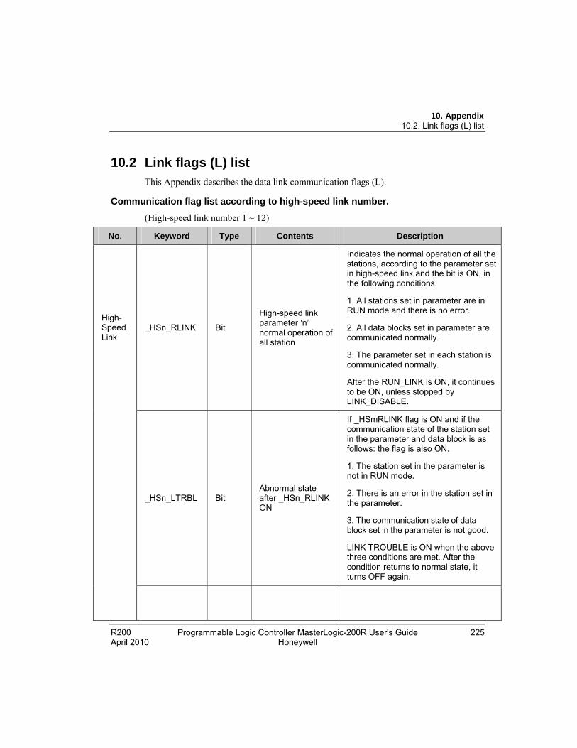
10. Appendix 10.2. Link flags (L) list
R200 Programmable Logic Controller MasterLogic-200R User's Guide 225 April 2010 Honeywell
10.2 Link flags (L) list This Appendix describes the data link communication flags (L).
Communication flag list according to high-speed link number.
(High-speed link number 1 ~ 12)
No. Keyword Type Contents Description
_HSn_RLINK Bit
High-speed link parameter ‘n’ normal operation of all station
Indicates the normal operation of all the stations, according to the parameter set in high-speed link and the bit is ON, in the following conditions.
1. All stations set in parameter are in RUN mode and there is no error.
2. All data blocks set in parameter are communicated normally.
3. The parameter set in each station is communicated normally.
After the RUN_LINK is ON, it continues to be ON, unless stopped by LINK_DISABLE.
_HSn_LTRBL Bit Abnormal state after _HSn_RLINK ON
If _HSmRLINK flag is ON and if the communication state of the station set in the parameter and data block is as follows: the flag is also ON.
1. The station set in the parameter is not in RUN mode.
2. There is an error in the station set in the parameter.
3. The communication state of data block set in the parameter is not good.
LINK TROUBLE is ON when the above three conditions are met. After the condition returns to normal state, it turns OFF again.
High-Speed Link

10. Appendix 10.2. Link flags (L) list
226 Programmable Logic Controller MasterLogic-200R User's Guide R200 Honeywell April 2010
No. Keyword Type Contents Description
_HSn_STATEk (k=000~127)
Bit Array
High-speed link parameter ‘n’, k block general state
Indicates the general state of communication information for each data block of setting parameter.
HS1STATEk=HS1MODk&_HS1TR X k&(~_HSnERRk )
_HSn_MODk
(k=000~127)
Bit Array
High-speed link parameter ‘n’, k block station RUN operation mode
Indicates operation mode of station set in k data block of the parameter.
_HSn_TRXk
(k=000~127)
Bit Array
Normal communication with High-speed link parameter ‘n’, k block station
Indicates if communication state of k data of parameter is communicated smoothly according to the setting.
_HSn_ERRk
(k=000~127)
Bit Array
High-speed link parameter ‘n’, k block station operation error mode
Indicates if errors occur in the communication state of k data block of parameter.
_HSn_SETBLOCKk
Bit Array
High-speed link parameter ‘n’, k block setting
Indicates whether or not to set k data block of parameter.

10. Appendix 10.2. Link flags (L) list
R200 Programmable Logic Controller MasterLogic-200R User's Guide 227 April 2010 Honeywell
ATTENTION
High- Speed Link no.
L area address Remarks
1 L000000~L00049F
2 L000500~L00099F
3 L001000~L00149F
4 L001500~L00199F
5 L002000~L00249F
6 L002500~L00299F
7 L003000~L00349F
8 L003500~L00399F
9 L004000~L00449F
10 L004500~L00499F
11 L005000~L00549F
Comparing with high-speed link 1 from [Table 1], the flag address of different high-speed link station number is as follows, computed by a simple formula:
Calculation formula : L area address =
L000000 + 500 x (High-speed link no. – 1)
In case of using high-speed line flag for Program and monitoring, you can use the flag map registered in SoftMaster.
‘k’ means block number and appears 8 words by 16 per word, for 128 blocks from 000~127.
For example, mode information (_HS1MOD) appears from block 0 to block 15 for L00010, and block 16~31, 32~47, 48~63, 64~79, 80~95, 96~111, 112~127 information for L00011, L00012, L00013, L00014, L00015, L00016, L00017. Thus, mode information of block number 55 appears in L000137.
Communication flag list according to P2P service setting
P2P parameter number (n) : 1~8, P2P block(xx) : 0~63
No. Keyword Type Contents Description
P2P _P2Pn_NDRxx Bit P2P parameter
n, xx
Block service normal
Indicates P2P parameter n, xx block service normal end.

10. Appendix 10.2. Link flags (L) list
228 Programmable Logic Controller MasterLogic-200R User's Guide R200 Honeywell April 2010
No. Keyword Type Contents Description
end
_P2Pn_ERRxx Bit
P2P parameter n, xx
Block service abnormal end
Indicates P2P parameter n, xx block service abnormal end.
_P2Pn_STATUSxx
Word
P2P parameter n, xx
Block service abnormal end error code
Indicates error code in case of P2P parameter n, xx block service abnormal end.
_P2Pn_SVCCNTxx
Double word
P2P parameter n, xx
Block service normal count
Indicates P2P parameter n, xx block service normal count.
_P2Pn_ERRCNTxx
Double word
P2P parameter n, xx
Block service abnormal count
Indicates P2P parameter n, xx block service abnormal count.

10. Appendix 10.3. Communication flags (P2P) list
R200 Programmable Logic Controller MasterLogic-200R User's Guide 229 April 2010 Honeywell
10.3 Communication flags (P2P) list
Link register list according to P2P number
P2P Parameter Number (n) : 1~8, P2P Block(xx) : 0~63
No. Flags Type Contents Description
N00000 _PnBxxSN
Word
P2P parameter n, xx block another station number
Saves another station number of P2P parameter 1, 00 block.
In case of using another station number at SoftMaster-NM, it is possible to edit while in RUN mode by using P2PSN command.
N00001 ~
N00004
_PnBxxRD1
Device structure
Area device 1 to read P2P parameter n, xx block
Saves area device 1 to read P2P parameter n, xx block.
N00005 _PnBxxRS1
Word
Area size 1 to read P2P parameter n, xx block
Saves area size 1 to read P2P parameter n, xx block.
N00006 ~
N00009
_PnBxxRD2
Device structure
Area device 2 to read P2P parameter n, xx block
Saves area device 2 to read P2P parameter n, xx block.
N00010 _PnBxxRS2
Word
Area size 2 to read P2P parameter n, xx block
Saves area size 2 to read P2P parameter n, xx block.
N00011 ~
N00014
_PnBxxRD3
Device structure
Area device 3 to read P2P parameter n, xx block
Saves area device 3 to read P2P parameter n, xx block.
N00015 _PnBxxRS3
Word
Area size 3 to read P2P parameter n, xx block
Saves area size 3 to read P2P parameter n, xx block.
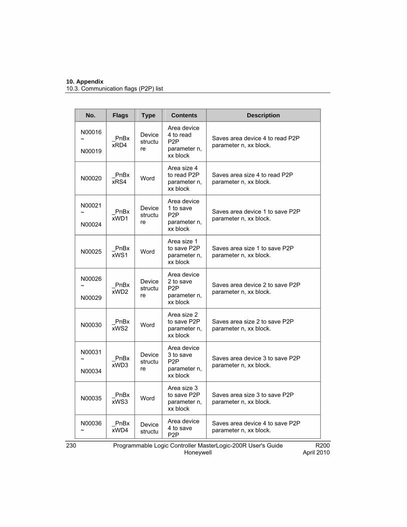
10. Appendix 10.3. Communication flags (P2P) list
230 Programmable Logic Controller MasterLogic-200R User's Guide R200 Honeywell April 2010
No. Flags Type Contents Description
N00016 ~
N00019
_PnBxxRD4
Device structure
Area device 4 to read P2P parameter n, xx block
Saves area device 4 to read P2P parameter n, xx block.
N00020 _PnBxxRS4
Word
Area size 4 to read P2P parameter n, xx block
Saves area size 4 to read P2P parameter n, xx block.
N00021 ~
N00024
_PnBxxWD1
Device structure
Area device 1 to save P2P parameter n, xx block
Saves area device 1 to save P2P parameter n, xx block.
N00025 _PnBxxWS1
Word
Area size 1 to save P2P parameter n, xx block
Saves area size 1 to save P2P parameter n, xx block.
N00026 ~
N00029
_PnBxxWD2
Device structure
Area device 2 to save P2P parameter n, xx block
Saves area device 2 to save P2P parameter n, xx block.
N00030 _PnBxxWS2
Word
Area size 2 to save P2P parameter n, xx block
Saves area size 2 to save P2P parameter n, xx block.
N00031 ~
N00034
_PnBxxWD3
Device structure
Area device 3 to save P2P parameter n, xx block
Saves area device 3 to save P2P parameter n, xx block.
N00035 _PnBxxWS3
Word
Area size 3 to save P2P parameter n, xx block
Saves area size 3 to save P2P parameter n, xx block.
N00036 ~
_PnBxxWD4
Device structu
Area device 4 to save P2P
Saves area device 4 to save P2P parameter n, xx block.
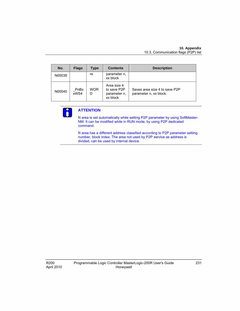
10. Appendix 10.3. Communication flags (P2P) list
R200 Programmable Logic Controller MasterLogic-200R User's Guide 231 April 2010 Honeywell
No. Flags Type Contents Description
N00039 re parameter n, xx block
N00040 _PnBxxWS4
WORD
Area size 4 to save P2P parameter n, xx block
Saves area size 4 to save P2P parameter n, xx block.
ATTENTION
N area is set automatically while setting P2P parameter by using SoftMaster-NM. It can be modified while in RUN mode, by using P2P dedicated command.
N area has a different address classified according to P2P parameter setting number, block index. The area not used by P2P service as address is divided, can be used by internal device.
10. Appendix 10.4. Reserved words
232 Programmable Logic Controller MasterLogic-200R User's Guide R200 Honeywell April 2010
10.4 Reserved words The following is a list of predefined words to be used in the system. These words must not be used as an identifier.
1. ACTION ... END_ACTION
2. ARRAY ... OF
3. AT
4. CASE ... OF ... ELSE ... END_CASE
5. CONFIGURATION ... END_CONFIGURATION
6. Name of Data Type
7. DATE#, D#
8. DATE_AND_TIME#, DT#
9. EXIT
10. FOR ... TO ... BY ... DO ... END_FOR
11. FUNCTION ... END_FUNCTION
12. FUNCTION_BLOCK ... END_FUNCTION_BLOCK
13. Names of Function Block
14. IF ... THEN ... ELSIF ... ELSE ... END_IF
15. OK
16. Operator (IL Language)
17. Operator (ST Language)
18. PROGRAM
19. PROGRAM ... END_PROGRAM
20. REPEAT ... UNTIL ... END_REPEAT
21. RESOURCE ... END_RESOURCE
22. RETAIN
23. RETURN

10. Appendix 10.4. Reserved words
R200 Programmable Logic Controller MasterLogic-200R User's Guide 233 April 2010 Honeywell
24. STEP ... END_STEP
25. STRUCTURE ... END_STRUCTURE
26. T#
27. TASK ... WITH
28. TIME_OF_DAY#, TOD#
29. TRANSITION ... FROM... TO ... END_TRANSITION
30. TYPE ... END_TYPE
31. VAR ... END_VAR
32. VAR_INPUT ... END_VAR
33. VAR_OUTPUT ... END_VAR
34. VAR_IN_OUT ... END_VAR
35. VAR_EXTERNAL ... END_VAR
36. VAR_ACCESS ... END_VAR
37. VAR_GLOBAL ... END_VAR
38. WHILE ... DO ... END_WHILE
39. WITH

10. Appendix 10.4. Reserved words
234 Programmable Logic Controller MasterLogic-200R User's Guide R200 Honeywell April 2010

Honeywell Process Solutions 1860 W. Rose Garden Lane Phoenix, AZ 85027 USA