MASTERING ELECTRICAL ENGINEERING - TPU
99
Transcript of MASTERING ELECTRICAL ENGINEERING - TPU
MASTERING
ELECTRICAL ENGINEERING
MACMILLAN MASTER SERIES
Banking Basic English Law Basic Management Biology British Politics Business Communication Chemistry COBOL Programming Commerce Computer Programming Computers Data Processing Economics Electrical Engineering Electronics English Grammar English Language English Literature French French 2
German Hairdressing Italian Keyboarding Marketing Mathematics Modern British History Modern World History Nutrition Office Practice Pascal Programming Physics Principles of Accounts Social Welfare Sociology Spanish Statistics Study Skills Typewriting Skills Word Processing
MASTERING ELECTRICAL ENGINEERING
NOEL M. MORRIS
M MACMILLAN
©Noel M. Morris 1985
All rights reserved. No reproduction, copy or transmission of this publication may be made without written permission.
No paragraph of this publication may be reproduced, copied or transmitted save with written permission or in accordance with the provisions of the Copyright Act 1956 (as amended).
Any person who does any unauthorised act in relation to this publication may be liable to criminal prosecution and civil claims for damages.
First published 1985
Published by MACMILLAN EDUCATION LTD Houndmills, Basingstoke, Hampshire RG21 2XS and London Companies and representatives throughout the world
Printed and bound in Great Britain by Anchor Brendon Ltd, Tiptree, Essex
British Library Cataloguing in Publication Data Morris, Noel M. Mastering electrical engineering.-(Macmillan master series) 1. Electric engineering I. Title 621.3 TK145 ISBN 0-333-38592-6 ISBN 0-333-38593-4 Pbk ISBN 0-333-38594-2 Pbk (export)
List of tables List of figures Preface
CONTENTS
Definitions of symbols used in equations Glossary
1 Principles of electricity 1.1 Atomic structure 1.2 Electronic 'holes 1.3 Conductors, semiconductors
and insulators 1.4 Voltage and current 1.5 Ohm's law 1.6 Conductance
v
XV
xvii xxiii XXV
xxvii
2
3 3 5 6
1.7 Linear and non-linear resistors 6
2 Electrochemistry batteries and other sources of e.m.f.
1.8 1.9
1.10
2.1 2.2 2.3 2.4 2.5 2.6 2.7 2.8 2.9 2.10 2.11 2.12 2.13 2.14 2.15
Alternating current Mutiples and submultiples of
units Some basic electrical
quantities Self-test questions Summary of important facts
Electrochemical effect Ions Electrolysis An example of electrolysis Electroplating Faraday's laws of electrolysis Cells and batteries A simple voltaic cell Internal resistance of a cell Limitations of simple cells The 'dry' cell Other types of primary cell Storage batteries Thermoelectricity The Hall effect
8
10
11 12 12
14 14 15 16 17 17 19 20 21 23 24 25 25 29 31
CONTENTS
2.16 The piezoelectric effect 32 2.17 The photovoltaic cell or solar
cell 32 Self-test questions 33 Summary of important facts 33
3 Resistors and electrical 3.1 Resistor types 35 circuits 3.2 Fixed resistors 35
3.3 Preferred values of resistance for fixed resistors 37
3.4 Resistance colour code 37 3.5 Variable resistors, rheostats
and potentiometers 40 3.6 Resistance of a conductor 41 3.7 Conductivity and conductance 46 3.8 Effect of temperature change
on conductor resistance 46 3.9 Superconductivity 49 3.10 Temperature effects on
insulators and on semi-conductors 49
3.11 What is an electrical circuit? 50 3.12 Circuit elements in series 50 3.13 Resistor in parallel 53 3.14 Series-parallel circuits 54 3.15 Kirchhoff's laws 56 3.16 An application of Kirchhoff's
laws 59 Self-test questions 61 Summary of important facts 62
4 Measuring instruments 4.1 Introduction 63 and electrical 4.2 Types of instrument 63 measurements 4.3 Effects utilised in analogue
instruments 64 4.4 Operating requirements of
analogue instruments 65 4.5 A galvanometer or moving-coil
instrument 65 4.6 Meter sensitivity and errors 67 4.7 Extension of the range of
moving-coil instruments 68 4.8 Measurement of a.c. quantities
using a moving-coil meter 71
vii
4.9 Moving-iron meters 72 4.10 Meter scales 73 4.11 Wattmeters 74 4.12 The energy meter or
kilowatt-hour meter 76 4.13 Measurement of resistance by
the Wheatstone bridge 77 4.14 Measurement of resistance
using an ohmmeter 81 4.15 Electronic instruments 82 4.16 Measurement of resistance
using a digital meter 83 Self-test questions 84 Summary of important facts 84
5 Electrical energy and 5.1 Heating effect of current: electrical tariffs fuses 86
5.2 Calculation of electrical energy 87 5.3 Applications of heating effects 89 5.4 Electricity supply tariffs 91 5.5 Maximum demand 91 5.6 A typical supply tariff 92 5.7 Electricity bills 92
Self-test questions 93 Summary of important facts 93
6 Electrostatics 6.1 Frictional electricity 94 6.2 The unit of electrical charge 95 6.3 Electric flux 95 6.4 A parallel-plate capacitor 96 6.5 Potential gradient or electric
field intensity 97 6.6 Electrostatic screening 97 6.7 Units of capacitance 98 6.8 Charge stored by a capacitor 98 6.9 Energy stored in a capacitor 99 6.10 Electric flux density 99 6.11 Permittivity of a dielectric 100 6.12 Capacitance of a parallel-
plate capacitor 101 6.13 Applications of capacitors 103 6.14 Multi-plate capacitors 105 6.15 Capacitors in series 106 6.16 Capacitors in parallel 108
CONTENTS
6.17 Capacitor charging current 109 6.18 The time constant of an
RC circuit 113 6.19 Capacitor discharge 113 6.20 Types of capacitor 115
Self-test questions 119 Summary of important facts 119
7 Electromagnetism 7.1 Magnetic effects 121 7.2 Magnetism 122 7.3 Magnetic field pattern of a
permanent magnet 123 7.4 Direction of the magnetic
field around a current-carrying conductor 123
7.5 Solenoids and electromagnets 125 7.6 Flux distribution around a
current-carrying loop of wire 126
7.7 Magnetic field produced by a current-carrying coil 127
7.8 Magnetomotive force or m.m.f. 128
7.9 Magnetic field intensity or magnetising force 128
7.10 Magnetic flux 129 7.11 Magnetic flux density 129 7.12 Permeability 130 7.13 Magnetisation curve for iron
and other ferromagnetic material 132
7.14 Hysteresis loop of a ferro-magnetic material 134
7.15 'Soft' and 'hard' magnetic materials 135
7.16 Magnetic circuit reluctance 136 7.17 Magnetic circuits 137 7.18 Magnetic screening 140 7.19 Electromagnetic induction 140 7.20 The laws of electromagnetic
induction 141 7.21 Self-inductance of a circuit 141
ix
7.22 Relationship between the self- 143 inductance of a coil and the number of turns on the 143 coil
7.23 Energy stored in a magnetic 143 field
7.24 Growth of current in an 146 inductive circuit 148
7.25 Decay of current in an inductive circuit 150
7.26 Breaking an inductive circuit 154 7.27 Applications of electro- 155
magnetic principles Self-test questions Summary of important facts 157
8 Electrical generators and 8.1 Principle of the electrical power distribution generator 158
8.2 The direction of induced 160 e.m.f. - Fleming's right-hand rule 163
8.3 Alternators or a.c. generators 164 8.4 Single-phase and poly-phase 167
a.c. supplies 8.5 Eddy currents 168 8.6 Direct current generators 8.7 Simplified equation of the d.c. 169
generator 8.8 An electricity generating 169
station 170 8.9 The a.c. electrical power 172
distribution system 8.10 d.c. power distribution 173 8.11 Power loss and efficiency 174 8.12 Calculation of the efficiency 175
of a machine Self-test questions 177 Summary of important facts
9 Direct current motors 9.1 The motor effect 177 9.2 The direction of the force on a
current-carrying conductor -Fleming's left-hand rule
CONTENTS
9.3 The force on a current-carrying 179 loop of wire 179
9.4 The d.c. motor principle 181 9.5 Construction of a d.c. motor 9.6 Magnitude of the force on a 182
current-carrying conductor 9.7 Torque produced by the 182
armature of a d.c. motor 9.8 'Back' e.m.f. induced in a d.c. 183
motor armature 184 9.9 Types of d.c. motor 9.10 Commutation problems in 187
d.c. machines 187 9.11 Motor starters 189
Self-test questions 189 Summary of important facts
10 Alternating current 10.1 Alternating quantities 191 10.2 Mean value or average value
of a sine wave 193 10.3 The effective value or root-
mean-square (r.m.s.) value of a sine wave 196
10.4 Average value and r.m.s. value of a wave of any shape 198
10.5 Form factor and peak factor of a waveform 199
10.6 Phase angle difference between two sine waves 200
10.7 Phasor diagrams 201 10.8 Addition of phasors 204 10.9 Volt-amperes, watts and
volt-amperes reactive 207 10.10 Power factor 211 10.11 Harmonics in a.c. systems 212
Self-test questions 215 Summary of important facts
.. 11 Introduction to single- 11.1 Resistance in an a.c. circuit 217
phase a.c. circuits 11.2 Pure inductance in an a.c. circuit 218
xi
11.3 Calculation of inductive 221 reactance, XL 222
11.4 X£, I and frequency 224 11.5 Capacitance in an a.c. circuit 11.6 Calculation of capacitative 227
reactance, Xc 228 11.7 Xc, I and frequency 11.8 Summary of voltage and 231
current relationships 11.9 Applications of inductive and 231
capacitive reactance 233 Self-test questions 233 Summary of important facts
12 Single-phase a.c. 12.1 A series R-L-C circuit 234 calculations 12.2 Voltage drop in circuit
elements 236 12.3 Circuit impedance, Z 237 12.4 Power in an a.c. circuit 239 12.5 Parallel a.c. circuits 241 12.6 Resonance in a.c. circuits 244 12.7 Series resonance 245 12.8 Q-factor or quality factor of
a series-resonant circuit 248 12.9 Features of series resonance 249 12.10 Parallel resonance 249 12.11 Current drawn by a parallel
resonant circuit 251 12.12 Q-factor of a parallel
resonant circuit 254 Self-test questions 255 Summary of important facts 256
13 Poly-phase a.c. circuits 13.1 Features of a poly-phase 257 supply
13.2 A simple two-phase 257 generator 258
13.3 A three-phase generator 13.4 'Balanced' and 'unbalanced' 260
three-phase systems 13.5 The three-phase, four-wire 261
star connection
CONTENTS
13.6 Three-phase, three-wire 264 star-connected system
13.7 Three-phase delta or mesh 264 connection
13-.8 Summary of star and delta 266 equations
13.9 Power consumed by a three- 266 phase load
13.10 VA, power and V Ar consumed by a balanced three-phase 267 load 269
Self-test questions 270 Summary of important facts
14 The transformer 14.1 Mutual inductance · 271 14.2 Coupling coefficient 272 14.3 Basic principle of the
transformer 273 14.4 Construction of a practical
transformer 276 14.5 Autotransformers or single-
winding transformers 277 14.6 Transformer efficiency 279 14.7 Instrument transformers 280 14.8 Using a transformer to
produce a two-phase supply 280 14.9 Three-phase transformers 281 14.10 A three-phase to six-phase
transformer 283 Self-test questions 283 Summary of important facts 285
IS a.c. motors 15.1 Principle of the a.c. motor 286 15.2 Rotating and 'linear' a.c.
motors 287 15.3 Producing a rotating or
moving magnetic field 287 15.4 A practical a.c. motor - the
inclusion motor 290 15.5 'Fractional slip' of an
induction motor 291 15.6 The synchronous motor 292
xiii
15.7 Single-phase induction motors 293
Self-test questions 294 Summary of important facts 294
16 Power electronics 16.1 Semiconductors 296 16.2 Semiconductor diodes (the
p-n diode) 297 16.3 Diode characteristic curves 300 16.4 Rectifier circuits 301 16.5 Single-phase, half-wave
rectifier circuit 301 16.6 Single-phase, full·wave
rectifier circuits 303 16.7 Smoothing circuits 306 16.8 The thyristor 307 16.9 A 'controlled' three-phase
power rectifier 313 16.10 Invertors 314 16.11 A standby power supply 314
Self-test questions 315 Summary of important facts 315
Solutions to numerical problems 317 Index 319

xiv
XV
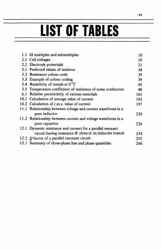
LIST OF TABLES 1.1 SI multiples and submultiples 10 2.1 Cell voltages 19 2.2 Electrode potentials 21 3.1 Preferred values of resistors 38 3.2 Resistance colour code 39 3.3 Example of colour coding 39 3.4 Resistivity of metals at 0 °C 45 3.5 Temperature coefficient of resistance of some conductors 48 6.1 Relative permittivity of various materials 101
10.1 Calculation of average value of current 195 10.2 Calculation of r.m.s. value of current 197 11.1 Relationship between voltage and current waveforms in a
pure inductor 220 11.2 Relationship between current and voltage waveforms in a
pure capacitor 226 12.1 Dynamic resistance and current for a parallel resonant
circuit having resistance R ohms in its inductive branch 254 12.2 Q-factor of a parallel resonant circuit 255 13.1 Summary of three-phase line and phase quantities 266

xvi
xvii
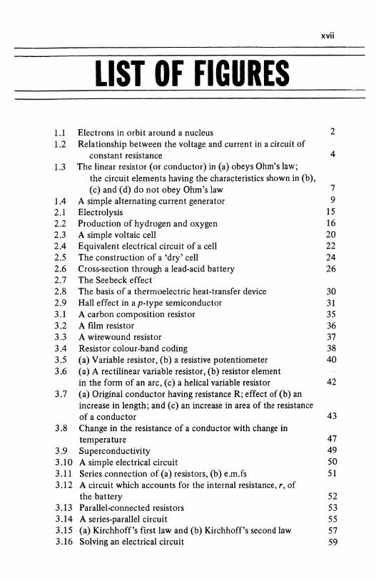
LIST OF FIGURES 1.1 Electrons in orbit around a nucleus 2 1.2 Relationship between the voltage and current in a circuit of
constant resistance 4 l.3 The linear resistor (or conductor) in (a) obeys Ohm's law;
the circuit elements having the characteristics shown in (b), (c) and (d) do not obey Ohm's law 7
1.4 A simple alternating current generator 9 2.1 Electrolysis 15 2.2 Production of hydrogen and oxygen 16 2.3 A simple voltaic cell 20 2.4 Equivalent electrical circuit of a cell 22 2.5 The construction of a 'dry' cell 24 2.6 Cross-section through a lead-acid battery 26 2.7 The Seebeck effect 2.8 The basis of a thermoelectric heat-transfer device 30 2.9 Hall effect in a p-type semiconductor 31 3.1 A carbon composition resistor 35 3.2 A film resistor 36 3.3 A wirewound resistor 37 3.4 Resistor colour-band coding 38 3.5 (a) Variable resistor, (b) a resistive potentiometer 40 3.6 (a) A rectilinear variable resistor, (b) resistor element
in the form of an arc, (c) a helical variable resistor 42 3.7 (a) Original conductor having resistance R; effect of (b) an
increase in length; and (c) an increase in area of the resistance of a conductor 43
3.8 Change in the resistance of a conductor with change in temperature 47
3.9 Superconductivity 49 3.10 A simple electrical circuit 50 3.11 Series connection of (a) resistors, (b) e.m.fs 51 3.12 A circuit which accounts for the internal resistance, r, of
the battery 52 3.13 Parallel-connected resistors 53 3.14 A series-parallel circuit 55 3.15 (a) Kirchhoff's first law and (b) Kirchhoff's second law 57 3.16 Solving an electrical circuit 59
xviii
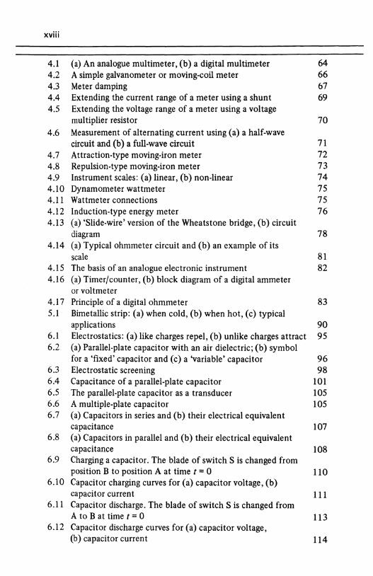
4.1 (a) An analogue multimeter, (b) a digital multimeter 64 4.2 A simple galvanometer or moving-coil meter 66 4.3 Meter damping 67 4.4 Extending the current range of a meter using a shunt 69 4.5 Extending the voltage range of a meter using a voltage
multiplier resistor 70 4.6 Measurement of alternating current using (a) a half-wave
circuit and (b) a full-wave circuit 71 4.7 Attraction-type moving-iron meter 72 4.8 Repulsion-type moving-iron meter 73 4.9 Instrument scales: (a) linear, (b) non-linear 74 4.10 Dynamometer wattmeter 75 4.11 Wattmeter connections 75 4.12 Induction-type energy meter 76 4.13 (a) 'Slide-wire' version of the Wheatstone bridge, (b) circuit
diagram 78 4.14 (a) Typical ohmmeter circuit and (b) an example of its
scale 81 4.15 The basis of an analogue electronic instrument 82 4.16 (a) Timer/counter, (b) block diagram of a digital ammeter
or voltmeter 4.17 Principle of a digital ohmmeter 83 5.1 Bimetallic strip: (a) when cold, (b) when hot, (c) typical
applications 90 6.1 Electrostatics: (a) like charges repel, (b) unlike charges attract 95 6.2 (a) Parallel-plate capacitor with an air dielectric; (b) symbol
for a 'fixed' capacitor and (c) a 'variable' capacitor 96 6.3 Electrostatic screening 98 6.4 Capacitance of a parallel-plate capacitor 101 6.5 The parallel-plate capacitor as a transducer 105 6.6 A multiple-plate capacitor 105 6.7 (a) Capacitors in series and (b) their electrical equivalent
capacitance 107 6.8 (a) Capacitors in parallel and (b) their electrical equivalent
capacitance 108 6.9 Charging a capacitor. The blade of switch S is changed from
position B to position A at time t = 0 110 6.10 Capacitor charging curves for (a) capacitor voltage, (b)
capacitor current 111 6.11 Capacitor discharge. The blade of switch S is changed from
A to B at time t = 0 113 6.12 Capacitor discharge curves for (a) capacitor voltage,
(b) capacitor current 114
xix
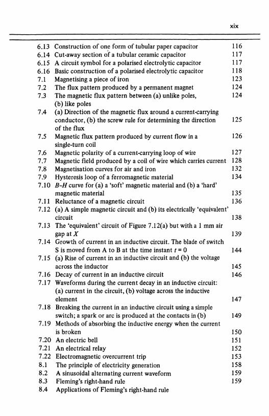
6.13 Construction of on~ form of tubular paper capacitor 116 6.14 Cut-away section of a tubular ceramic capacitor 117 6.15 A circuit symbol for a polarised electrolytic capacitor 117 6.16 Basic construction of a polarised electrolytic capacitor 118 7.1 Magnetising a piece of iron 123 7.2 The flux pattern produced by a permanent magnet 124 7.3 The magnetic flux pattern between (a) unlike poles, 124
(b) like poles 7.4 (a) Direction of the magnetic flux around a current-carrying
conductor, (b) the screw rule for determining the direction 125 of the flux
7.5 Magnetic flux pattern produced by current flow in a 126 single-turn coil
7.6 Magnetic polarity of a current-carrying loop of wire 127 7.7 Magnetic field produced by a coil of wire which carries current 128 7.8 Magnetisation curves for air and iron 132 7.9 Hysteresis loop of a ferromagnetic material 134 7.10 B-H curve for (a) a 'soft' magnetic material and (b) a 'hard'
magnetic material 135 7.11 Reluctance of a magnetic circuit 136 7.12 (a) A simple magnetic circuit and (b) its electrically 'equivalent'
circuit 138 7.13 The 'equivalent' circuit of Figure 7.12(a) but with a 1 mm air
gap at X 139 7.14 Growth of current in an inductive circuit. The blade of switch
S is moved from A to B at the time instant t = 0 144 7.15 (a) Rise of current in an inductive circuit and (b) the voltage
across the inductor 145 7.16 Decay of current in an inductive circuit 146 7.17 Waveforms during the current decay in an inductive circuit:
(a) current in the circuit, (b) voltage across the inductive element 147
7.18 Breaking the current in an inductive circuit using a simple switch; a spark or arc is produced at the contacts in (b) 149
7.19 Methods of absorbing the inductive energy when the current is broken 150
7.20 An electric bell 151 7.21 An electrical relay 152 7.22 Electromagnetic overcurrent trip 153 8.1 The principle of electricity generation 158 8.2 A sinusoidal alternating current waveform 159 8.3 Fleming's right-hand rule 159 8.4 Applications of Fleming's right-hand rule
XX
8.5 A simple s'ngle-loop alternator 160 8.6 The stator winding of a 3750 kVA alternator 162 8.7 Sinusoidal voltage waveform 163 8.8 A simple alternator with slip rings 164 8.9 (a) Eddy c•.ments induced in the iron circuit, (b) reduction
of eddy currents by laminating the iron circuit 166 8.10 A shtple single-loop d.c. generator 167 8.11 A simplified diagram of an electrical power station 169 8.12 The national power distribution system 171 9.1 Fleming's left-hand rule 178 9.2 An application of Fleming's left-hand rule 178 9.3 Force on a current-carrying loop of wire 179 9.4 The basis of a d.c. motor 180 9.5 d.c. machine construction 181 9.6 Motor 'back' e.m.f. 183 9.7 d.c. motor connecfons 185 9.8 Simplified starter for a d.c. shunt motor 188
10.1 A sinusoid1l curren~ waveform 192 10.2 The 'mean· value or ·~verage' value of an a.c. wave 194 10.3 The r.m.s. value of an alternating wave 196 10.4 Mean and r.m.s. values of a non-sinusoidal wave 199 10.5 Phase angle differepce 201 10.6 Production of a sinewave 202 10.7 Several pnasor diagrams for Figure 1 0.6(b) 202 10.8 Phasor diagrams for a voltage wave and a current wave which
are out of phJse with one 1nother 203 10.9 Phasor addition of voltages 204 10.10 The phasor sum of rwo voltages 205 10.11 Determination of the voltage V T 206 10.12 (a) Waveform diagram fur a sinusoidal voltage wave and a
current wave which a:e in phase with one another and (b) the corresponding volt-ampere product wave 207
10.13 Waveforms of voltage, curre:1t and volt-ampere product for two waves which are 45° out of ph~se with one another 208
10.14 Waveforms for a phase angle of 90°; the average value of the power consumed is zero 209
10.15 The power triangle of an a.c. circuit 210 10.16 (a) A linear characteristic and (b) a non-linear characteristic 213 10.17 Complex wave formed from (a) a fundamental and a second
harmonic which are in phase with one another, (b) a fundamental and a second harmonic which lags by 90° 214
11.1 A pure resistor in an a.c. circuit 217 11.2 A pure inductor in an a.c. circuit 219
xxi
11.3 Inductive reactance, current and frequency 223 11.4 Pure capacitance in an a.c. circuit 226 ll.5 Capacitive reactance, current and frequency 229 11.6 A full-wave rectifier and smoothing circuit with waveforms 230 12.1 An R-L-C series circuit 234 12.2 Phasor diagrams for (a) R, (b) Land (c) C in Figure 12.1. The
phasor diagram for the complete circuit is shown in (d) 235 12.3 (a) The voltage triangle for a series circuit and (b) the
impedance triangle 238 12.4 The equivalent circuit of (a) a practical coil, (b) a practical
capacitor 240 12.5 A series a.c. circuit calculation 241 12.6 Phasor diagram for an R-L series circuit 241 12.7 . A parallel a.c. circuit 242 12.8 Phasor diagrams for (a) the resistive branch, (b) the inductive
branch, (c) the capacitive branch and (d) the complete circuit 243 12.9 Resonance in an a.c. circuit 245 12.10 Series resonance 246 12.11 Frequency response of an R-L-C series circuit 247 12.12 Parallel resonance 251 12.13 Current at resonance in a parallel circuit 252 12.14 Waveforms in a parallel resonant circuit 253 12.15 Current-frequency graph for a parallel circuit having various
resistance values 254 13.1 (a) A single-phase generator, (b) a simple two-phase 258
generator 13.2 A three-phase generator 259 13.3 An unbalanced three-phase supply 260 13.4 The three-phase, four-wire star connection 261 13.5 Phase and line voltage and currents in a star-connected
system 262 13.6 Determining the line voltage V R y 263 13.7 The three-phase, three-wire star connection 264 13.8 The delta or mesh connection of a three-phase generator
and load 265 14.1 Mutual inductance: the basis of the transformer 272 14.2 (a) A simple transformer, (b) circuit symbol 274 14.3 (a) Core-type magnetic circuit construction, (b) shell-type
construction 277 14.4 (a) Concentric winding construction and (b) sandwich
winding construction 278 14.5 Autotransformer with (a) a step-down voltage ratio, (b) a
step-up voltage ratio 278
xxii
14.6 Use of a centre-tapped secondary winding to produce a two-phase (hi-phase) supply 281
14.7 Windings on one limb of a three-phase transformer 281
14.8 (a) A three-phase delta-star transformer and (b) connection diagram 282
14.9 A three-phase to six-phase transformer 284
15.1 (a) How current is induced in a rotor conductor and (b) the direction of the force on the induced current 286
15.2 Production of a rotating magnetic field 288
15.3 Construction of the rotor of a cage induction motor 290 15.4 A single-phase, capacitor-start induction motor 294 16.1 A p-n junction diode 297 16.2 Photograph of (a) a signal diode and (b) a power diode 298 16.3 A selection of heat sinks 299 16.4 Static anode characteristic of a diode 300 16.5 Block diagram of a rectifier 301 16.6 Single-phase, half-wave rectifier circuit 302 16.7 Single-phase, full-wave (a) centre-tap circuit and (b) bridge
circuit 304 16.8 Voltage and current waveforms for a single-phase, full-wave
rectifier circuit 305 16.9 (a) Choke-input fllter circuit and (b) a 1r-fllter 307 16.10 (a) Sectional diagram of a p-n-p-n reverse blocking thyristor,
(b) circuit symbols and (c) a practical thyristor 309 16.11 Simplified operation of the thyristor 310 16.12 Characteristic of a reverse blocking thyristor 310 16.13 Circuit symbols for a triac or bidirectional thyristor 311 16.14 Characteristic of a triac 312 16.15 A controlled three-phase bridge rectifier 313 16.16 One form of standby power supply 314
xxiii
PREFACE In common with other books in the Mastering series, the intention is to set out in one book the basis of a complete subject -Electrical Engineering in this volume.
This book reflects the modern thinking and needs of the electrical technologist, emphasis being placed on practical circuits and systems. Following modern teaching practice in many courses, the mathematics has been kept to a minimum consistent with covering the necessary background theory.
Mastering Electrical Engineering is suitable for use as a self-teaching book, each chapter being supported not only by worked examples but also by self-test questions and a summary of important facts. The latter feature is very useful for the reader who is in a hurry to get a 'feel' for the subject matter in the chapter.
Starting with the principles of electricity and sources of electromotive force (e.m.f.), the book covers the basis of 'heavy current' electrical engineering including circuit theory, alternating cu"ent (a.c.) and direct cu"ent (d.c.) machines, single-phase and three-phase calculations, transformers, electrical power distribution, instruments and power electronics.
The book contains a liberal supply of illustrations to highlight the features of each chapter, and it is hoped that the approach will stimulate the reader with the same enthusiasm for the subject that the author holds for it.
I would like to thank the electrical manufacturing industry at large for the support it has given, particular thanks being due to the following:
RS Components (for figs 16.2, 16.3 and 16.10c) GEC Machines Celdis Ltd. AVO Ltd
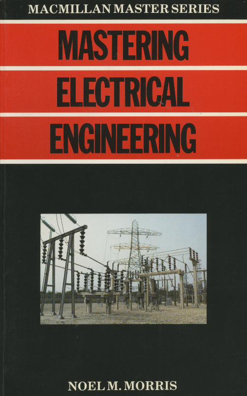
The author and publishers wish to thank the Southern Electricity Board for permission to use the cover illustration of one of the Board's substations.
The author would also like to thank Elizabeth Black and Keith Povey, through Macmillan Education, for their invaluable assistance in tidying up the manuscript.
Finally, I must thank my wife for her help, patience and support during the months whilst the book was being written.
North Staffordshire Polytechnic NOEL M. MORRIS

xxiv
XXV
DEFINITIONS OF SYMBOLS USED IN
EQUATIONS A, a area in m2
B magnetic flux density in tesla (T) C capacitance in farads (F) C unit of electrical charge (coulombs) D electric flux density in coulombs per square meter (C/m2 )
d diameter and distance in metres (m) E, e e.m.f. or p.d. in volts (V) E electric field intensity or potential gradient in volts per metre
(V/m) e base of Naperian logarithms= 2.71828 F magnetomotive force in ampere-turns or in amperes (A) F mechanical force in newtons (N) F unit of capacitance (farads) f frequency in hertz (Hz) f0 resonant frequency in hertz (Hz) G conductance in siemens (S) H magnetic field intensity or magnetising force in ampere-turns per
metre or amperes per metre (A/m) H unit of inductance (henrys) I, i current in amperes (A) K a constant of an electrical machine k magnetic circuit coupling coefficient (dimensionless) L self-inductance of a magnetic circuit in henrys (H) I length in metres (m) M mutual inductance between magnetic circuits in henrys (H) N number of turns on a coil N, n speed of rotation of the rotating part of a motor in revolutions per
minutes (rev/min) or revolutions per second (rev/s) P power in watts (W) Q electric charge of electrostatic flux in coulombs (C)
xxvi
Q Q-factor of a resonant circuit (dimensionless) Q reactive volt-amperes (V Ar) in an a.c. circuit R, r resistance in ohms (il) S magnetic circuit reluctance (resistance to flux) in ampere-turns per
weber or amperes per weber (A/Wb) S shunt resistance connected to a meter S volt-amperes (VA) in an a.c. circuit s fractional slip of an induction motor rotor (dimensionless) T periodic time of an alternating wave in seconds (s) T time constant of an electrical circuit in seconds (s) T torque in newton metres (N m)
time in seconds (s) V, v voltage or p.d. in volts (V) W energy in joules (J) or in watt seconds (W s) Xc capacitive reactance in ohms (Q) XL inductive reactance in ohms (Q) Z impedance of an a.c. circuit in ohms (Q) a temperature coefficient of resistance in cq-1
e absolute permittivity of a dielectric in farads per metre (F /m) Eo permittivity offree space= 8.85 x 10⁻¹² F/m Er relative permittivity of a dielectric (dimensionless) 'Tl efficiency of an electrical machine 8 temperature in ° C or K 8 angular measurement in degrees or radians p. absolute permeability of a magnetic material in henrys per metre
(H/m) #J.o permeability of free space = 41T x 10-7 H/m IJ.r relative permeability (dimensionless) 1T a constant= 3.142 p resistivity of an electrical conductor in ohm metres (Q m) a conductivity of a conductor in siemens per metre (S/m) <I> magnetic flux in webers (Wb) tf> phase angle in degrees or radians cos tf> power factor of an a.c. circuit w angular frequency in rad/s of an a.c. supply w speed of rotation of the rotating part of an electric machine in
rad/s w0 resonant frequency in rad/s
xxvii
GLOSSARY Words in italics are mentioned elsewhere in the Glossary.
a.c. An abbreviation for alternating cu"ent acceptor circuit A series resonant circuit which has a very low resistance
to current flow at the resonant frequency, that is, it 'accepts' a high current
a.c. machine An electromechanical energy convertor which converts energy from an a. c. source into mechanical energy or vice versa
accumulator An electrical storage battery, that is, a battery which can be recharged by passing direct cu"ent through it
alternating current A current which alternately flows in one direction and then in the opposite direction
alternator An alternating current generator ammeter An instrument for the measurement of electrical cu"ent ampere The unit of electrical cu"ent ampere-tum The unit of magnetic field intensity (H) or magnetising force,
which is calculated from amperes x turns on the coil; since 'turns' are dimensionless, it is given the unit of the 'ampere' by electrical engineers
anode (1) In a diode it is the electrode by which the cu"ent(hole flow) enters; (2) In electrolysis, it is the electrode to which negative ions are attracted
apparent power In an a.c. circuit, it is the product, volts x amperes (or the volt-ampere [VA] product)
armature (1) The rotating part of a d.c. machine; (2) In a relay, it is a piece of ferromagnetic material which is attracted towards the pole of the electromagnet
autotransformer A transformer having a single winding average value The average value of an alternating wave. An alternative
name is mean value back e.m.f. The e.m.f. induced in an inductor when the cu"ent through
it changes battery A group of cells connected together brush A piece of specially shaped carbon or graphite which connects
either the commutator of a d. c. machine or the rotor of an a. c. machine to the external circuit
cage rotor motor A popular form of induction motor in which the rotor consists of metal rods (copper or aluminium) embedded in a laminated
xxviii
iron circuit, the bars being short-circuited by means of 'end rings' at the ends of the rotor
capacitance The property of a capacitor which enables it to store electrical charge
capacitive reactance The opposition of a capacitor to the flow of alternating current. No power is dissipated in a pure capacitive reactance. Symbol Xc, measured in ohms
capacitor Consists of two conducting surfaces or 'plates' separated by an insulating dielectric, which has the ability to store electric charge
cathode (1) In a diode, it is the electrode by which the current (hole flow) leaves; (2) In electrolysis, it is the electrode to which the positive ions are attracted
cell Converts chemical energy into electrical energy circuit An interconnected set of conductors coercive force The magnetising force needed to demagnetise completely
a piece of magnetised material commutator Consists of a large number of conducting segments con
nected to the armature winding of a d. c. machine, each segment being isolated from adjacent segments; Current enters the armature via graphite brushes
complex wave A wave which contains a fUndamental frequency together with a number of harmonic frequencies
compound-wound machine A d.c. machinehavingpartofitsfield winding in series with its armature, and part connected in shunt with the armature
conductance Reciprocal of resistance. Symbol G, and measured in siemens (S)
conductivity Reciprocal of resistivity conductor An element which freely allows the flow of electric current core loss Energy loss in an electrical machine as a result of the combined
effects of hysteresis loss and eddy current loss coulomb The unit of electrical charge, symbol C current Rate of flow of electrical charge. Symbol I, and measured in
amperes (A) d.c. Abbreviation of direct current d.c. machine An electromechanical energy convertor which converts
energy from a d.c. source into mechanical energy or vice versa depolarising agent A chemical included in a cell to prevent polarisation dielectric An insulating material which separates the plates of a capacitor diode A two-electrode device, the electrodes being the anode and the
cathode direct current Current which flows in one direction only, that is, a uni
directional current
xxix
eddy current Current induced in the iron circuit of an electrical machine because of changes in magnetic flux
efficiency Ratio of the power output from a machine or circuit to its input power; expressed as a per centage if the ratio is multiplied by 100, and is dimensionless
electric field intensity The potential gradient in volts per metre in the material
electric flux A measure of the electrostatic field between two charged plates; measured in coulombs
electric flux density The amount of electric flux passing through one square metre of material
electrode (1) In a semiconductor device it is an element which either emits current or collects it; (2) In an electrolytic cell it is a metallic conductor where the ions give up their charge
electrolysis A chemical change brought about by the passage of direct current through an electrolyte
electrolyte A substance which, when dissolved, produces a conducting path in the solvent (which may be water)
electromagnet A current-carrying coil with an iron core electromagnetic induction The production of an e.m.f in a circuit,
arising from a change in the amount of magnetic flux linking the circuit electromotive force The p.d. measured at the terminals of a cell, battery
or generator when no current is drawn from it; abbreviated to e.m.f and measured in volts
electron A negative charge carrier, and a constituent part of every atom e.m.f. Abbreviation for electromotive force energy meter A meter used to measure energy, usually in kilowatt hours
(kWh) exciter A d.c. generator which provides the current for (that is, it
'excites') the field winding of an alternator or synchronous motor farad The unit of capacitance, symbol F; submultiples such as the micro
farad, the nanofarad and the picofarad are in common use Faraday's laws (1) The laws of electrolysis relate to the mass of substance
liberated in the process of electrolysis; (2) the law of electromagnetic induction relates to the induced e.m.f in a circuit when the magnetic flux associated with the circuit changes
ferromagnetic material A material which can be strongly magnetised in the direction of an applied magnetising force
field winding A winding on an electrical machine which produces the main magnetic field
Fleming's rules The left-hand rule relates to motor action, the right-hand rule relates to generator action
frequency The number of oscillations per second of an alternating wave;
XXX
measured in hertz (Hz) full-wave rectifier A circuit which converts both the positive and negative
half-cycle of an alternating cu"ent wave into direct cu"ent (more precisely, unidirectional current)
fundamental frequency The frequency of a sinusoidal wave which is the same as that of the complex wave of which it is a part
galvanometer A moving-coil meter used to measure small values of current generator An electromechanical energy convertor which changes mech
anical energy into electrical energy half-wave rectifier Converts one of the half-cycle of an a.c. waveform
into direct (unidirectional) cu"ent, but prevents current flow in the other half cycle
hard magnetic material A material which retains much of its magnetism after the magnetising force has been removed
harmonic frequency A multiple of the fundamental frequency of a complex wave
henry Unit of inductance, symbol H hertz Unit of frequency, symbol Hz; equal to 1 cycle per second hole A positive charge carrier; can be regarded as the absence of an
electron where on would normally be found hysteresis loss Energy loss caused by the repeated reversals of magnetic
domains in a fe"omagnetic material in the presence of an alternating magnetic field
impedance Total opposition of a circuit to the flow of alternating cu"ent; symbol Z, measured in ohms
induced e.m.f. e.m.f. induced in a circuit either by a changing magnetic flux or by a strong electric field
inductance A measure of the ability of a circuit to produce a magnetic field and store magnetic energy
induction motor An a.c. motor which depends for its operation on a 'rotating' or 'moving' magnetic field
inductive reactance The opposition of a pure inductance to the flow of alterating cu"ent; no power is dissipated in an inductive reactance; symbol XL, measured in ohns
inductor A piece of apparatus having the property of inductance instrument transformer A transformer designed to connect an electrical
instrument either to a high voltage (a voltage transformer, VT, or potential transformer, PT) or to a high cu"ent (a current transformer, CT)
insulator A material which has a very high resistance to the flow of electrical cu"ent. Ideally, no current flows through an insulator
internal resistance The resistance 'within' a cell, battery, generator or power supply
xxxi
invertor A circuit which converts direct voltage or direct cu"ent into alternating voltage or alternating cu"ent
ion An atom or molecule which is electrically charged; can be either negatively or positively charged
ionisation The process by which an atom or molecule is converted into anion
joule The unit of energy equal to 1 watt x 1 second junction The connection of two or more wires in a circuit; node is an
alternative name Kirchhoff's laws (1) The total cu"ent flowing towards a junction is equal
to the total current flowing away from it; (2) the algebraic sum of the p.d.s. and e.m.fs around any closed mesh is zero
lamination A thin sheet of iron, many of which are grouped together to form a magnetic circuit; used to reduce eddy cu"ent
magnetic circuit An interconnected set of ferromagnetic branches in which a magnetic flux is established
magnetic coupling coefficient A dimensionless number having a value between zero and unity which gives the proportion of the magnetic flux which arrives at a second (secondary) coil after leaving the primary winding; symbol k
magnetic domain A group of atoms in a fe"omagnetic material which form a localised magnetic field system
magnetic field intensity The m.m.f. per unit length of a magnetic circuit; symbol H; measured in ampere-turns per metre or amperes per metre
magnetic flux A measure of the magnetic field produced by a pennanent magnet or electromagnet; symbol <P; measured in webers (Wb)
magnetic flux density The amount of magnetic flux passing through an area of 1 m2 ; symbol B, measured in tesla (T)
magnetic leakage Magnetic flux which does not follow the 'useful' magnetic path
magnetic leakage coefficient The ratio of the total magnetic flux to the 'useful' magnetic flux; has a value 1.0 or greater
magnetising force An alternative name for magnetic field intensity magnetomotive force The 'force' which produces a magnetic flux; symbol
F, measured in ampere-turns or amperes; abbreviation m.m.f. mean value The average value of an alternating wave motor An electromechanical energy convertor which changes electrical
energy into mechanical energy mutual inductance The property of a system which causes a change of
cu"ent in one circuit to induce a voltage in another circuit negative charge carrier An electron node Alternative name for junction non-linear resistor A resistor which does not obey Ohm~ law
xxxii
n-type semiconductor A semiconductor material which has been 'doped' so that it has mobile negative charge carriers
ohm The unit of electrical resistance or impedance, symbol .Q \
ohmmeter A moving-coil instrument used to measure resistance Ohm's law This states that, at a constant temperature, the current in a
pure resistor is directly proportional to the p.d. across it parallel circuit A circuit in which all the elements have the same voltage
across them parallel resonant circuit An a.c. parallel circuit containing resistance,
inductance and capacitance which resonates with the supply frequency; known as a rejector circuit, it has a high impedance at resonance, and the circulating current within the circuit is higher than the supply current
p.d. Abbreviation for potential difference Peltier effect When a current flows in a circuit consisting of dissimilar
semiconductors or metals, the Peltier effect describes why one junction is heated and the other is cooled
periodic time The time taken for one cycle of an a.c. wave to be completed
permanent magnet A piece of ferromagnetic material which has been permanently magnetised. Both its remanence or retentivity and its coercive force are high
permeability The ratio of the magnetic flux density (B) in a material to the magnetic field intensity (H) needed to produce it. Also known as the absolute permeability of the material. Symbol JJ., measured in henrys per metre (H/m)
permeability of free space The permeability of a vacuum (or, approximately, of air), symbol JJ.o = 47T x 10-7 H/m
permeability (relative) The ratio of the absolute permeability of a magnetic material to the permeability of free space; symbol f.lr, and is dimensionless
phase angle The angular difference in degrees or radians between two sinusoidally varying quantities or between two phasors
phasor A line which is scaled to represent the r.m.s. value of a waveform and whose angle represents its displacement from a phasor in the horizontal 'reference' direction
piezoelectric effect The production of an e.m.f between two faces of a crystal when it is subject to mechanical pressure. The effect is reversible
polarisation A chemical effect in a cell which causes the anode to be coated with hydrogen bubbles
pole (I) A terminal of a cell; (2) one end of a permanent magnet or an electromagnet
xxxiii
poly-phase supply An a.c. supply having many ('poly') phases; the three-phase supply is the most popular type
positive charge carrier A hole potential A measure of the ability of a unit charge to produce cu"ent potential difference The difference in electrical potential between two
points in a circuit potentiometer (1) A resistor having a sliding contact; (2) a device or
circuit for comparing electrical potentials power The useful output from an electrical machine and the rate of doing
work; symbol P, measured in watts (W) or joules per second power factor The ratio in an a.c. circuit of the power in watts to the
apparent power in volt-amperes primary cell A cell which cannot be recharged primary· winding The winding of a transformer which is connected to the
a.c. supply source p-type semiconductor A semiconductor material which has been 'doped'
so that it has mobile positive charge earners (holes) Q-factor The 'quality' factor of a resonant circuit; it indicates, in a series
resonant circuit, the value of the voltage 'magnification' factor and, in a parallel resonant circuit, the value of the cu"ent 'magnification' factor
radian An angular measure given by the ratio of the arc length to the radius; there are 2tr radians in a circle
reactance The property of a reactive element, that is, a pure capacitor or a pure inductor, to oppose the flow of alternating cu"ent; power is not consumed by a reactive element
reactive volt-ampere Also known as reactive 'power'; associated with current flow in a reactive element; 'real' power is not absorbed; symbol Q, measured in volt-amperes reactive (V Ar)
rectifier A circuit which converts alternating voltage or current into direct (unidirectional) voltage or current
rejector circuit A parallel resonant circuit which has a very high resistance to cu"ent flow at the resonant frequency, that is, it 'rejects' current
reluctance The ratio of the magnetomotive force (F) in a magnetic circuit to the magnetic flux (4>) in the circuit; it is the effective resistance of the circuit to magnetic flux; symbol S, measured in ampere-turns per weber or in amperes per weber
remanence The remaining magnetic flux in a specimen of magnetic material after the magnetising force has been removed; also known as the residual magnetism or retentivity
residual magnetism Another name for remanence resistance A measure of the ability of a material to oppose the flow of
cu"ent through it; symbol R, measured in ohms
xxxiv
resistivity The resistance of a unit cube of material, calculated by resistance X tea~::h. Symbol p, measured in ohm meters (Q m)
resistor A circuit element having the property of resistance resonance The condition of an a. c. circuit when it 'resounds' or resonates
in sympathy with the supply frequency; the impedance of the circuit at this frequency is purely resistive
resonant frequency The frequency at which the circuit resonates. Symbol w0 (rad/s) or f0 (Hz)
retentivity Another name for remanence rheostat A variable resistor r.m.s. Abbreviation for root-mean-square root-mean-square The a.c. value which has the same heating effect as the
equivalent d.c. value; abbreviated to r.m.s. and also known as the 'effective value'
rotor The rotating part of a machine (usually associated with a.c. machines)
saturation (magnetic) The state of a fe"omagnetic material when all its domains are aligned in one direction
secondary cell A cell which can be recharged by passing d. c. through it secondary winding The winding of a transformer which is connected to
the electricall oad Seebeck effect The e.m.f between two dissimilar metals when their
junctions are at different temperatures self-inductance An alternative name for inductance semiconductor A material whose conductivity is mid-way between that
of a good conductor and that of a good insulator semiconductor junction A junction between an n-type semiconductor
and a p-type semiconductor; a diode has one p-n junction, and a junction transistor has two p-n junctions
separately excited machine A d.c. machine whose field windings and armature are supplied from separate power supplies
series circuit A circuit in which all the elements carry the same current series motor A d.c. motor whose field windings are connected in series
with the armature; mainly used for traction applications series resonant circuit An a.c. series circuit containing reactive elements
which resonates with the supply frequency. Known as an acceptor circuit, it has a low impedance at resonance, so that the resonant current is high, i.e., it 'accepts' cu"ent. The voltage across each of the reactive elements (inductance and capacitance) is higher than the supply voltage
shunt An alternative name for parallel connection shunt wound machine A d. c. machine whose field windings are connected
in shunt (parallel) with the armature
XXXV
single-phase supply An a. c. supply system carried between two lines, one line usually being 'live' and the other being 'neutral', that is, at 'earth potential'
slip (fractional) The difference between the synchronous speed of the rotating field and the rotor speed of an induction motor expressed as a ratio of the synchronous speed, symbols, and is dimensionless
slip ring A metal ring which is on, but is insulated from, the shaft of a rotating electrical machine; its function is to convey cu"ent to or from the rotating part of the machine (usually an a.c. machine) via carbon brushes. An a.c. machine may have two or more slip rings
smoothing circuit A circuit which 'smooths' or 'fllters' the variations in the output voltage from a rectifier circuit
soft magnetic material A magnetic material which easily loses its magne-tism; its coercive force is low
solenoid A coil with an air core squirrel cage motor Alternative name for a cage rotor motor storage battery Alternative name for accumulator synchronous motor An a. c. motor whose rotor runs at synchronous speed terminal voltage The p.d. between the terminals of a cell, battery or
generator when an electrical load is connected to it testa The unit of magnetic flux density, symbol T thermistor A semiconductor device whose resistance changes with tem
perature (usually a decrease in resistance with increase in temperature, but could be an increase in resistance)
thermocouple A junction of two dissimilar metals which develops an e.m.f. when it is heated or cooled relative to the remainder of the circuit
thermopile Several thermocouples connected in series to give a higher e.m.f. than a single thermocouple
three-phase supply A poly-phase supply having three phases; a 'balanced' or 'symmetrical' three-phase supply has three equal voltages which are displaced from one another by 120°
testa The unit of magnetic flux density, symbol T thyristor A four-layer semiconductor device for the control of 'heavy'
cu"ent by electronic means torque Turning moment (force x radius) produced by a rotating machine transformer Device which 'transforms' or changes voltage and cu"ent
levels in an a. c. circuit; uses the principle of mutual inductance transient A phenomenon which persists for a short period of time after
a change has occurred in the circuit transistor A three-layer semiconductor n-p-n or p-n-p device used in
electronic amplifiers and computers triac A multi-layer semiconductor device for the bidirectional control of
xxxvi
cu"ent by electronic means; it is one of the thyristor family of elements two-part tariff A method of charging for the cost of electricity; one part
of the tariff is related to the 'standing' charges associated with the generating plant, the other being related to the 'running' charges
universal motor A motor which can operate on either a.c. or d.c.; a hand-held electrical drilling machine is an example
volt The unit of electromotive force and potential difference, symbol V voltage dependent resistor A resistor whose resistance is dependent on
the p.d. across it; it is a non-linear resistor voltmeter An instrument for the measurement of voltage watt The unit of electrical power, symbol W wattmeter An instrument for measuring electrical power weber The unit of magnetic flux, symbol Wb Wheatstone bridge A circuit for the measurement of resistance zener diode A diode with a well-defined reverse breakdown voltage,
which can be operated in the reverse breakdown mode
CHAPTER 1
PRINCIPLES OF ELECTRICITY
1.1 ATOMIC STRUCTURE
About 100 basic substances or chemical elements are known to man, each element consisting of a number of smaller parts known as atoms. Each atom comprises several much smaller particles, the principle ones being electrons, protons and neutrons.
The difference between the smaller particles lies not only in their difference in mass (a proton is 1840 times more 'massive' than an electron), but also in the electrical charge associated with them. For example, a proton has a positive electrical charge whilst an electron has a negative electrical charge; the charge on the proton is equal to but of opposite polarity to that on the electron. The electrical charge on either the proton or the electron is very small, in fact it is so small that one ampere of current is associated with the movement of over six million billion electrons per second.
The mass of the neutron is equal to that of the proton, but it has no electrical charge. In the latter respect it has little use in electrical circuits.
The nature of matter ensures that each atom is electrically balanced, that it has as many electrons as it has protons. Under certain circumstances an atom, or a molecule, or a group of atoms can acquire an electrical charge; the atom or group of atoms is then known as an ion. A negative ion (an anion) contains more electrons than are necessary for electrical neutrality; a positive ion (a cation) contains fewer electrons than necessary for neutrality.
The protons and neutrons are concentrated in the centre or nucleus of the atom as shown in Figure 1.1. The electrons orbit around the nucleus in what are known as layers, or energy bands or shells. A simple analogy of an atom is that of a multi-storey car park. The ground level, or 'zero energy' level can be regarded as the nucleus of the atom, whilst the higher found. The ground level is filled with 'car parking for staff cars' which we
2
fig 1 .1 electrons in orbit around a nucleus
electrons in orbit
atomic nucleus
will regard as protons and neutrons. As other people come along to park their cars, they must do so in the 'higher energy' levels. So it is with atoms - the lower shells are filled with electrons before the higher shells.
The electrons which take part in the process of electrical conduction are in the outermost shell or highest energy level shell of the electron; this is known as the valence sheD or valence energy band. For an electron to take part in electrical conduction, it must be free to 'move' within its energy band. In the multi-storey car park analogy this is equivalent to the cars on the uppermost floor having the most room to move about.
1.2 ELECTRONIC 'HOLES'
The application of an electrical voltage to a conductor results in electrons in the outermost shell (the valence shell) being subjected to an electrical force. This force tries to propel the electrons towards the positive pole of the supply; if the force is sufficiently great, some electrons escape from the forces which bind them to the atom. The electrons which arrive at the positive pole of the battery constitute flow of electrical current.
However, when an atom loses an electron its electrical neutrality is lost, and the remainder of the atom takes on a net positive charge. This positive charge will attract any mobile electron in its vicinity; in this way, when an electron moves from one part of the conductor to another, it leaves behind it a resulting positive charge (arising from the loss of the electron at that point). Thus, as the electron 'moves' in one direction, a positive charge 'moves' in the opposite direction. On this basis, it is possible to describe the mobile positive charge as a hole into which any electron can fall (a
3
'hole' may be thought of as the absence of an electron where one would normally be found).
Electrical engineers therefore think of a mobile negative charge ca"ier as an electron, and a mobile positive charge carrier as a hole.
1.3 CONDUCTORS, SEMICONDUCTORS AND INSULA TORS
A conductor is an electrical material (usually a metal) which offers very little resistance to electrical current. The reason that certain materials are good conductors is that the outer orbits (the valence shells) in adjacent atoms overlap one another, allowing electrons to move freely between the atoms.
An insulator (such as glass or plastic) offers a very high resistance to current flow. The reason that some materials are good insulators is that the outer orbits of the atoms do not overlap one another, making it very difficult for electrons to move through the material.
A semiconductor is a material whose resistance is midway between that of a good conductor and that of a good insulator. Other properties are involved in the selection of a semiconductor material for electrical and electronic purposes; these properties are discussed later in the book. Commonly used semiconductor materials include silicon and germanium (in diodes, transistors and integrated circuits), cadmium sulphide (in photoconductive cells), gallium arsenide (in lasers, and light-emitting diodes), etc. Silicon is the most widely used material, and is found in many rocks and stones (sand is silicon dioxide).
1.4 VOLTAGE AND CURRENT
Voltage is the electrical equivalent of mechanical potential. If a person drops a rock from the first storey of a building, the velocity that the rock attains on reaching the ground is fairly small. However, if the rock is taken to the twentieth floor of the building, it has a much greater potential energy and, when it is dropped it reaches a much higher velocity on reaching the ground. The potential energy of an electrical supply is given by its voltage and the greater the voltage of the supply source, the greater its potential to produce electrical current in any given circuit connected to its terminals (this is analagous to the velocity of the rock in the mechanical case). Thus the potential of a 240-volt supply to produce current is twenty times that of a 12-volt supply.
The electrical potential between two points in a circuit is known as the potential difference or p.d. between the points. A battery or electrical generator has the ability to produce current flow in a circuit, the voltage which produces the current being known as the electromotive force
4
(e.m.f.). The term electromotive force strictly applies to the source of electrical energy, but is sometimes (incorrectly) confused with potential difference. Potential difference and e.m.f. are both measured in volts, symbol V.
The current in a circuit is due to the movement of charge carriers through the circuit. The charge carriers may be either electrons (negative charge carriers) or holes (positive charge carriers), or both. Unless stated to the contrary, we will assume conventional cu"ent flow in electrical circuit, that is we assume that current is due to the movement of positive charge carriers (holes) which leave the positive terminal of the supply source and return to the negative terminal. The current in an electrical circuit is measured in amperes, symbol A, and is sometimes (incorrectly) referred to as 'amps'.
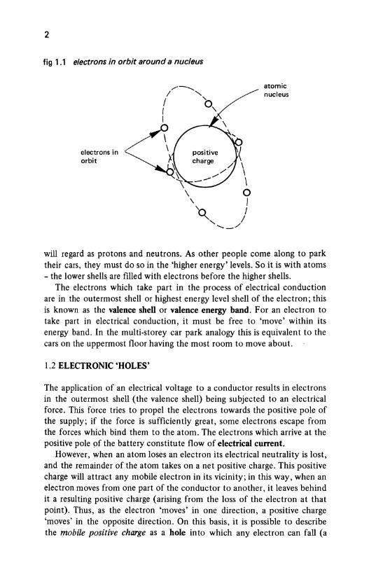
A simple electrical circuit comprising a battery of e.m.f. 10 V which is connected to a heater of ftxed resistance is shown in Figure 1.2( a); let us suppose that the current drawn by the heater is 1 A. If two 10-V batteries are connected in series with one another, as shown in Figure 1.2(b ), the
fig 1 .2 relationship between the voltage and current in a circuit of constant resistance
battery
1A
(a)
4
<l: 3 ... c: t 2 :J u
2A
~ "''"' tit 10 v 20 vI t 10 v
(b)
0 10 20 30 40
voltage, V
(c)
/
- heater '-
'
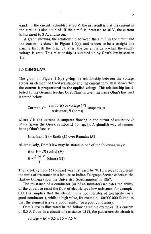
5
e.m.f. in the circuit is doubled at 20 V; the net result is that the current in the circuit is also doubled. If the e.m.f. is increased to 30 V, the current is increased to 3 A, and so on.
A graph showing the relationship between the e.m.f. in the circuit and the current is shown in Figure 1.2(c), and is seen to be a straight line passing through the origin; that is, the current is zero when the supply voltage is zero. This relationship is summed up by Ohm's law in section 1.5.
1.5 OHM'S LAW
The graph in Figure 1.2(c) giving the relationship between the voltage across an element of fixed resistance and the current through it shows that the current is proportional to the applied voltage. This relationship (attributed to the German teacher G. S. Ohm) is given the name Ohm's law, and is stated below
e.m.f. (E) or voltage (V) A Current, I= amperes,
resistance, R (ohms)
where I is the current in amperes flowing in the circuit of resistance R ohms (given the Greek symbol Q [omega]). A ghoulish way of remembering Ohm's law is:
Interi'nent (/)=Earth (E) over Remains (R)
Alternatively, Ohrn's law may be stated in one of the following ways:
E or V = IR (volts) (V) Eor V
R =-- (ohms)(Q) I
The Greek symbol Q (omega) was first used by W. H. Preece to represent the units of resistance in a lecture to Indian Telegraph Service cadets at the Hartley College (now the University, Southampton) in 1867.
The resistance of a conductor (or of an insulator) indicates the ability of the circuit to resist the flow of electricity; a low resistance, for example, 0.001 n, implies that the element is a poor resistor of electricity (or a good conductor!), whilst a high value, for example, 100000000 Q implies that the element is a very good resistor (or a poor conductor).
Ohm's law is illustrated in the following simple examples. If a current of 0.5 A flows in a circuit of resistance 15 n, the p.d. across the circuit is
voltage= IR = 0.5 x 15 = 7.5 V
6
Also, if an e.m.f. of 10 Vis applied to a circuit of resistance 10 000 n, the current in the circuit is
E 10 I=-=-- =0.0001A
R 10000
You should note that the resistance of a conductor may vary with temperature, and the effect of temperature on resistance is studied in detail in Chapter 3.
1.6CONDUCTANCE
In some cases it is convenient to use the reciprocal of resistance, that is~ rather than resistance itself. This reciprocal is known as the conductance, symbol G, of the conductor; this value indicates the ability of the circuit to conduct electricity. The unit of conductance is the siemens (symbolS), and
1 conductance, G = - S
R
A very low value of conductance, e.g., 0.000 000 0001 S implies that the circuit is a poor conductor of electricity (and is a good insulator), whilst a high value of conductance, e.g., 1000 S implies that it is a good conductor (or poor resistor). For example, a conductor of resistance 0.001 n has a conductance of
1 G = - = 1/0.001 = 1000 S
R
whilst an insulator of resistance 10 000 000 n has a conductance of
G = !_ = --1-- = 0.000 000 1 S R 10000000
1. 7 LINEAR AND NON-LINEAR RESISTORS
The majority of metals are good conductos and the current-voltage relationship for these materials obeys Ohm's law; that is, the I-V graph passes through the origin (see Figure 1.3(a)), and an increase in voltage (either positive or negative) produces a proportional change in the current. That is to say
I o: V
where the Greek symbol o: (alpha) means 'is proportional to'. In such a circuit element, doubling the voltage across the element has the effect of doubling the current through it.
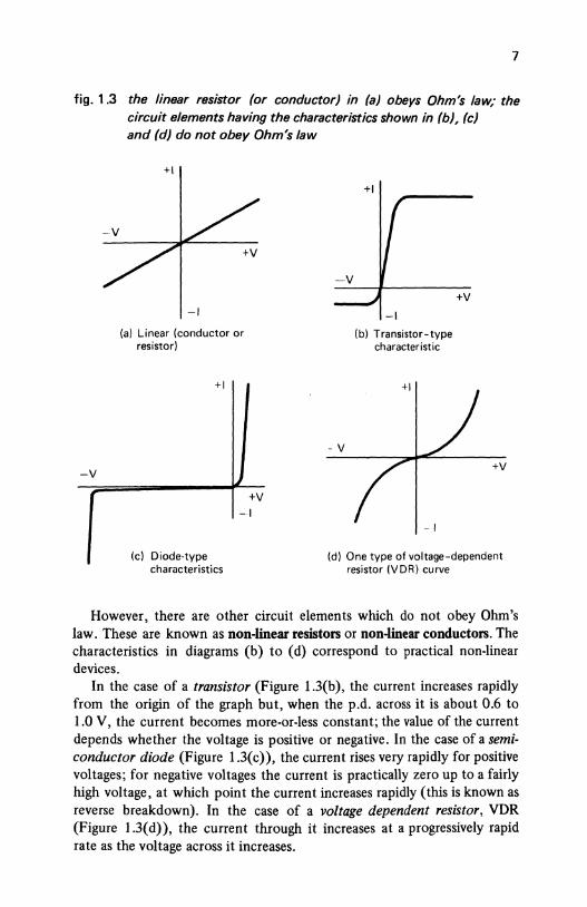
7
fig. 1.3 the linear resistor (or conductor) in (a) obeys Ohm's law; the circuit elements having the characteristics shown in (b), (c)
-V
and (d) do not obey Ohm's law
+I
-I
(a) Linear (conductor or resistor)
+I
(c) Diode-type characteristics
+V -I
- v
+I
-I
(b) Transistor-type characteristic
-I
+V
+V
(d) One type of voltage-dependent resistor (VDR) curve
However, there are other circuit elements which do not obey Ohm's law. These are known as non-linear resistors or non-linear conductors. The characteristics in diagrams (b) to (d) correspond to practical non-linear devices.
In the case of a transistor (Figure 1.3(b), the current increases rapidly from the origin of the graph but, when the p.d. across it is about 0.6 to 1.0 V, the current becomes more-or-less constant; the value of the current depends whether the voltage is positive or negative. In the case of a semiconductor diode (Figure 1.3(c)), the current rises very rapidly for positive voltages; for negative voltages the current is practically zero up to a fairly high voltage, at which point the current increases rapidly (this is known as reverse breakdown). In the case of a voltage dependent resistor, VDR (Figure 1.3( d)), the current through it increases at a progressively rapid rate as the voltage across it increases.
8
Although the I-V characteristic of the devices in Figure 1.3 may not obey Ohm's law, each finds its own special applications in electrical engineering. The following applications are typical:
Transistors - amplifiers and computers Diodes - rectifiers and invertors (the first converts a.c. to d.c. while
the latter converts d.c. to a.c.) Voltage dependent resistor- protection of electrical circuits from
voltage surges.
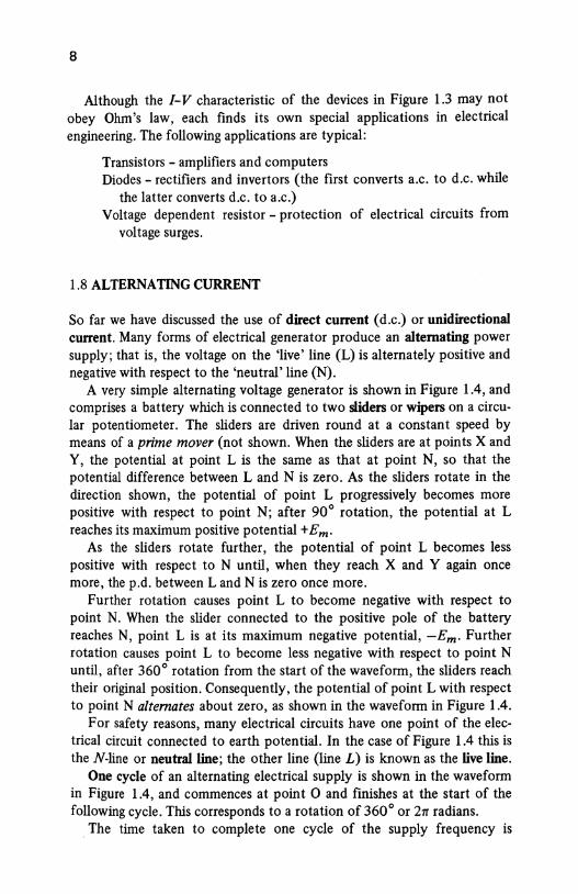
1.8 ALTERNATING CURRENT
So far we have discussed the use of direct current (d.c.) or unidirectional current. Many forms of electrical generator produce an alternating power supply; that is, the voltage on the 'live' line (L) is alternately positive and negative with respect to the 'neutral' line (N).
A very simple alternating voltage generator is shown in Figure 1.4, and comprises a battery which is connected to two sliders or wipers on a circular potentiometer. The sliders are driven round at a constant speed by means of a prime mover (not shown. When the sliders are at points X and Y, the potential at point L is the same as that at point N, so that the potential difference between L and N is zero. As the sliders rotate in the direction shown, the potential of point L progressively becomes more positive with respect to point N; after 90° rotation, the potential at L reaches its maximum positive potential +Em·
As the sliders rotate further, the potential of point L becomes less positive with respect to N until, when they reach X and Y again once more, the p.d. between Land N is zero once more.
Further rotation causes point L to become negative with respect to point N. When the slider connected to the positive pole of the battery reaches N, point L is at its maximum negative potential, -Em· Further rotation causes point L to become less negative with respect to point N until, after 360° rotation from the start of the waveform, the sliders reach their original position. Consequently, the potential of point L with respect to point N alternates about zero, as shown in the waveform in Figure 1.4.
For safety reasons, many electrical circuits have one point of the electrical circuit connected to earth potential. In the case of Figure 1.4 this is theN-line or neutral line; the other line (line L) is known as the live line.
One cycle of an alternating electrical supply is shown in the waveform in Figure 1.4, and commences at point 0 and finishes at the start of the following cycle. This corresponds to a rotation of 360° or 21T radians.
The time taken to complete one cycle of the supply frequency is
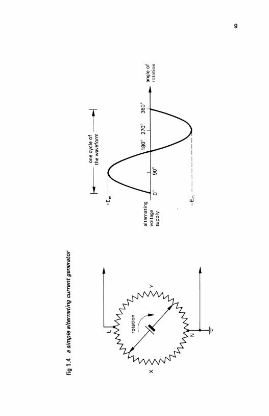
fig 1
.4
a si
mpl
e al
tern
atin
g cu
rren
t gen
erat
or
X
y
-::-
alte
rna
ting
I~
one
cycl
e o
f .,.I
r
. -
the
wa
vefo
rm
volta
ge
-L-----'---~1----'----+----~
sup
ply
-Em
-
-
angl
e o
f ro
tati
on
co
10
known as the periodic time of the wave. If this time is T seconds, then the frequency ,f, of the wave (the number of cycles per second} is given by
1 frequency,[= - hertz (Hz)
T
where 1 hertz is 1 cycle per second. If the periodic time of the wave is 1 ms, the frequency is
1 frequency,[= -- = =1000Hz.
1 ms 1 x 10⁻³
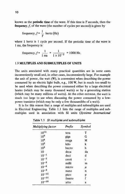
1.9 MULTIPLES AND SUBMULTIPLES OF UNITS
The units associated with many practical quantities are in some cases inconveniently small and, in other cases, inconveniently large. For example the unit of power, the watt (W), is convenient when describing the power consumed by an electric light bulb, e.g., 100 W, but is much too small to be used when describing the power consumed either by a large electrical heater (which may be many thousand watts) or by a generating station (which may be many millions of watts). At the other extreme, the watt is much too large to use when discussing the power consumed by a lowpower transistor (which may be only a few thousandths of a watt).
It is for this reason that a range of multiples and submultiples are used in Electrical Engineering. Table 1.1 lists the range of multiples and submultiples used in association with SI units (Systeme International
Table 1.1 Sl multiples and submultiples
Multiplying factor Prefix Symbol
1012 tera T 109 giga G 106 mega M 103 kilo k 102 hecto h 10 dec a da w-1 deci d w-2 centi c w-3 milli m w-6 micro 11 w-9 nano n 10-12 pi co p 10-1s femto f 10-1s atto a
11
d'Unites), which is the system of units adopted by Electrical and Electronic Engineers.
For example, 11 000 000 watts could be written either as 11 x 106 W or as 11 MW; 0.0001 W could be written either as 10-4 W or as 0.1 mW or as 100 p.W. Strictly speaking, any of the prefixes in Table 1.1 can be used but, in practice, deca- and hecto- are practically never used; femto- and attorefer to very small values indeed, and have only a limited use.
You should also note that compound prefixes are avoided wherever possible; for example, the multiple 10-9 is described as nano- rather than milli-micro. That is, 1 o-9 metre (m) is described as 1 nm and not as 1 m p.m.
1.10 SOME BASIC ELECTRICAL QUANTITIES
Some of the more commonly used units in electrical and electronic engineering are briefly described below.
Electrical quantity (symbol Q) The quantity of electricity passing a point in an electrical circuit is
Quantity, Q =I (amperes) x t (seconds) coulombs (C)
For example, if a circuit carries a current of 5 amperes for 15 seconds, the quantity of electricity is
Quantity, Q =It= 5 x 15 = 75 C
Electrical power (symbol P) Power is the rate of dissipation of energy and is given by
Power, P = E (volts) xI (amperes) watts (W)
If the electrical voltage across a resistive circuit element is 240 V, and if the current passing through it is 13 A, the power consumed is
Power,P = EI = 240 x 13 = 3120 W
Also from Ohm's law, E = IR, hence
Power, P = EI = (IR) x I= I 2 R W
Since I= ~ , then
E £2 Power, P = EI = E x - - - W
R R
12
Electrical energy (symbol W) The energy dissipated in an electrical circuit is given by
Energy, W = E (volts) xI (amperes) x t (seconds) joules (J)
If the p.d. across a circuit element is 100 V and it carries a current of 10 A for 15 s, the energy consumed is
Energy, W =Eft= 100 x 10 x 15 = 15 000 J or watt-seconds.
The commercial unit of electrical energy is the kilowatt-hour or kWh, which corresponds to 1 kilowatt of power being consumed continuously for a period of one hour.
SELF -TEST QUESTIONS
1. What is the difference btween an atom and a chemical element? How do electrons, protons and neutrons differ?
2. Copper is a conductor and glass is an insulator. Why do these materials have different electrical resistance? Why is a 'semiconductor' so named?
3. Explain the terms 'voltage' and 'potential drop'. 4. Using Ohm's law, calculate the current flowing in a resistance of 100 il
which has a p.d. of 20 V across it. 5. Calculate the conductance in siemens of a circuit which carries a cur
rent of 100 A, the p.d. across the circuit being 10 V. 6. The following values of current were measured in a circuit when the
voltage across the circuit was (i) 10 V, (ii) 20 V, (iii)30 V: 10 A, 40 A, 150 A. Plot the /-V characteristic of the circuit and state if it is linear or non-linear.
7. An alternating current waveform has a periodic time of 1 ms, calculate the frequency of the current. What is the periodic time of an alternating voltage offrequency 100kHz?
8. A current of 20 A flows in a circuit for 20 s, the voltage applied to the circuit being 20 V. Calculate the electrical quantity, the power and the energy consumed.
SUMMARY OF IMPORTANT FACTS
A chemical element is built up from atoms. Each atom is made up of electrons, protons and neutrons. The electron has a negative charge and the proton a positive charge; the two electrical charges are equal and opposite, but the mass of the proton is 1840 times greater than that of the electron.
Current flow is a combination of electron flow (negative charge carriers) and hole flow (positive charge carriers).
13
A conductor offers low resistance to current flow, an insulator offers high resistance. The resistance of a semiconductor is mid-way between the two extremes.
Voltage or e.m.f. is a measure of the potential of an electric circuit to produce current flow.
Ohm's law states that
E = IR
I E --R
R E --I
where E is in volts, I in amperes and R in ohms. The conductance (G) of an electrical circuit is measured in siemens (S)
and G = ..! (R in ohms). A linfar circuit element is one whose resistance is constant despite
fluctuations of voltage and current. The resistance of a non-linear circuit element varies with fluctuations of voltage and current.
A direct current or unidirectional current always flows in the same direction around a circuit. An alternating current periodically reverses its direction of flow. If the periodic time of an alternating wave is T seconds, the frequency of the alternating wave is[=~ Hz.
14 CHAPTER 2
ELECTROCHEMISTRY, BATTERIES AND OTHER
SOURCES OF e.m.f. 2.1 ELECTROCHEMICAL EFFECT
The chemical effect of an electric current is the basis of the electroplating industry; the flow of electric current between two electrodes (one being known as the anode and the other as the cathode) in a liquid (the electrolyte) causes material to be lost from one of the electrodes and deposited on the other.
The converse is true, that is, chemical action can produce an e.m.f. (for example, in an electric battery).
All these electrochemical effects depend on the electrolyte. The majority of pure liquids are good insulators (for example, pure water is a good insulator), but liquids containing salts will conduct electricity. You should also note that some liquids such as mercury (which is a liquid metal) are good conductors.
2.2 IONS
An atom has a nucleus (positively charged) surrounded by electrons (negatively charged) which orbit around the nucleus in shells or layers. In an electrically neutral atom, the positive and negative charges are equal to one another and cancel out. However, the electrons in the outermost orbit (the valence electrons) are fairly loosely attracted to the parent atom and can easily be detached. In fact, it is possible for either a chemical reaction or an electric field to cause an atom either to lose an electron or to gain one.
When an atom loses an electron, its charge balance is upset and the parent atom (which has lost the negatively charged electron) is left with a charge of+ 1 unit of electricity (equivalent to the charge on a proton). In this case the parent atom is described as a positive ion or a cation; the ion retains the characteristics of the original element because the nucleus
15
remains intact. When an atom gains an electron, it has a net charge of -1 unit of electricity (equivalent to the charge on one electron) and is described as a negative ion or anion.
Since like charges attract and unlike charges repel, a negative ion is attracted to a positively charged electrode and is repelled by a negatively charged electrode (and vice versa for a positive ion). For this reason, current flow can take place in ionised material as follows: in liquids such as electrolytes and in gases (for instance, in fluorescent tubes) current flow is due to the movement of ions between two oppositely charged electrodes, the current flow being known as ionisation current.
Ions are formed in a liquid either when a salt or an acid is dissolved in it; additionally, when a metal is immersed either in an alkaline or an acid solution, ionisation occurs. The resulting liquid is a fairly good conductor of electricity and is known as an electrolyte.
2.3 ELECTROLYSIS
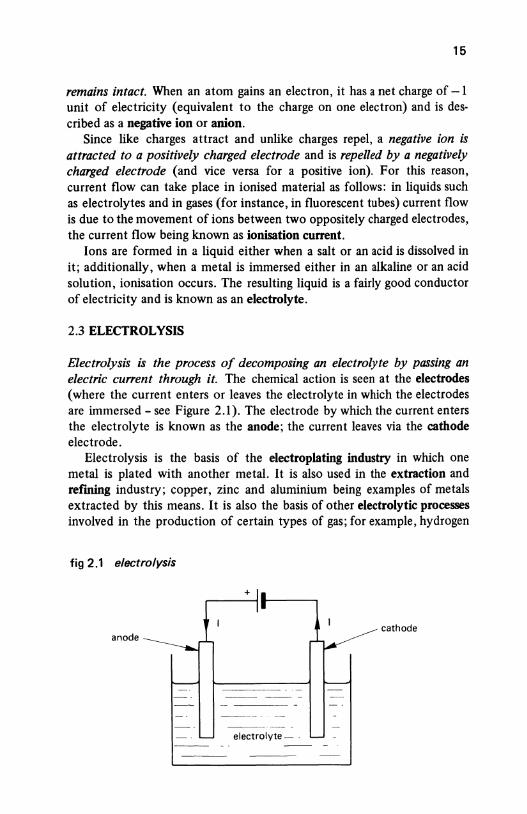
Electrolysis is the process of decomposing an electrolyte by passing an electric cu"ent through it. The chemical action is seen at the electrodes (where the current enters or leaves the electrolyte in which the electrodes are immersed- see Figure 2.1). The electrode by which the current enters the electrolyte is known as the anode; the current leaves via the cathode electrode.
Electrolysis is the basis of the electroplating industry in which one metal is plated with another metal. It is also used in the extraction and refming industry; copper, zinc and aluminium being examples of metals extracted by this means. It is also the basis of other electrolytic processes involved in the production of certain types of gas; for example, hydrogen
fig 2.1 electrolysis
+
cathode anode
electrolyte- -
16
and oxygen can be produced by breaking down water into its basic chemical constituents.
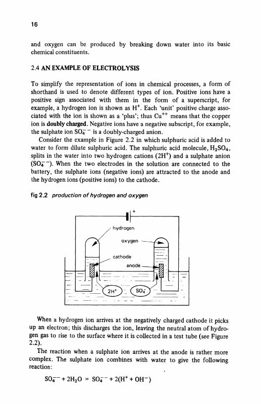
2.4 AN EXAMPLE OF ELECTROLYSIS
To simplify the representation of ions in chemical processes, a form of shorthand is used to denote different types of ion. Positive ions have a positive sign associated with them in the form of a superscript, for example, a hydrogen ion is shown as H+. Each 'unit' positive charge associated with the ion is shown as a 'plus'; thus Cu++ means that the copper ion is doubly charged. Negative ions have a negative subscript, for example, the sulphate ion S04- is a doubly-charged anion.
Consider the example in Figure 2.2 in which sulphuric acid is added to water to form dilute sulphuric acid. The sulphuric acid molecule, H2S04 ,
splits in the water into two hydrogen cations (2H~ and a sulphate anion (S04-). When the two electrodes in the solution are connected to the battery, the sulphate ions (negative ions) are attracted to the anode and the hydrogen ions (positive ions) to the cathode.
fig 2.2 production of hydrogen and oxygen
+
, hydrogen
oxygen
cathode
anode ---.~/.1
When a hydrogen ion arrives at the negatively charged cathode it picks up an electron; this discharges the ion, leaving the neutral atom of hydrogen gas to rise to the surface where it is collected in a test tube (see Figure 2.2).
The reaction when a sulphate ion arrives at the anode is rather more complex. The sulphate ion combines with water to give the following reaction:
= (2H+ + S04) + 20H
= H2S04 + 2QH-
17
The first line shows that the water dissociates into H+ and OH- ions, which further combine to produce sulphuric acid (H2S04) and OH- ions. The OH- ions rearrange themselves into water and oxygen as follows:
20H- = H20 +a--The negative charge associated with the o-- is discharged at the anode, the resulting neutral atoms of oxygen rise to the surface and are collected in the test tube.
From this, you will see that the sulphuric acid is constantly being replaced by the process and is not diminished, but the water is converted into its basic elements, namely, hydrogen and oxygen gas. Clearly, unless the water is replenished, the concentration of the acid increases slowly with time. Since the amount of acid is constant, it can be regarded as a catalyst.
2.5 ELECTROPLATING
When two different metals are immersed in a solution which is a salt of the same material as the anode, and a current is passed between the two metals, metal ions from the anode dissolve into the solution and, at the same time, ions of the anode material are deposited on the cathode.
Copper plating If the anode is of copper and the electrolyte is copper sulphate, the cathode (of, say, iron) is plated with copper.
Silver plating A silver anode is used and the electrolyte is cyanide of silver; the cathode must be a metal which does not chemically react with the electrolyte.
2.6 FARADAY'S LAWS OF ELECTROLYSIS
In the process of electrolysis, ions migrate towards the electrodes and, on arrival at the electrodes, give up some electrical charge. The charge given up per ion is
charge per ion = ze coulombs
where z is the number of valence electrons and e is the charge per electron. Hence the total charge Q given up by N ions is
Q = Nze coulombs (2.1)
18
or
number ofions,N= Q ze
Michael Faraday discovered this relationship in 1833, and stated two laws which govern electrolysis as follows:
First law:
The mass of material deposited (or gas released) is proportional to the quantity of electricity (current x time) which passes through the electrolyte.
(This is suggested by Eqn (2.1 ).)
Second law:
The mass of material in grammes deposited by the passage of 26.8 ampere hours of electricity is equal to the chemical equivalent of that material.
Example When an electrical current passes through a solution of sodium chloride in water, sodium hydroxide and hydrochloric acid are produced. If the chemical equivalent of sodium hydroxide is 40 and that of hydrochloric acid is 36.5, determine how much hydrochloric acid and sodium hydroxide are produced when 100 A flows for 10 ruins.
Solution
I= 100 A t = 10 mins = _!_ hour , 6
1 Q =It = 100 x - = 16.67 Ah
6
From Faraday's second law of electrolysis:
mass of material deposited
h . 1 . 1 quantity of electricity in Ah = c em1ca eqUiva en t x ---'-------':____ ___ __::____ __ 26.8
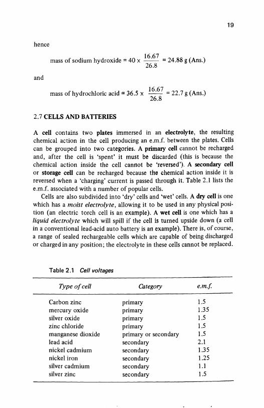
hence
and
f d h d d 40 16 ·67 = 24.88 g (Ans.) mass o so ium y roxi e = x 26.8
mass of hydrochloric acid= 36.5 x 16·67 = 22.7 g (Ans.) 26.8
2. 7 CELLS AND BATTERIES
19
A cell contains two plates immersed in an electrolyte, the resulting chemical action in the cell producing an e.m.f. between the plates. Cells
can be grouped into two categories. A primary cell cannot be recharged
and, after the cell is 'spent' it must be discarded (this is because the chemical action inside the cell cannot be 'reversed'). A secondary cell
or storage cell can be recharged because the chemical action inside it is reversed when a 'charging' current is passed through it. Table 2.1 lists the
e.m.f. associated with a number of popular cells. Cells are also subdivided into 'dry' cells and 'wet' cells. A dry cell is one
which has a moist electrolyte, allowing it to be used in any physical posi
tion (an electric torch cell is an example). A wet cell is one which has a
liquid electrolyte which will spill if the cell is turned upside down (a cell
in a conventional lead-acid auto battery is an example). There is, of course,
a range of sealed rechargeable cells which are capable of being discharged
or charged in any position; the electrolyte in these cells cannot be replaced.
Table 2.1 Cell voltages
Type of cell Category e.m.f
Carbon zinc primary 1.5 mercury oxide primary 1.35 silver oxide primary 1.5 zinc chloride primary 1.5 manganese dioxide primary or secondary 1.5 lead acid secondary 2.1 nickel cadmium secondary 1.35 nickel iron secondary 1.25 silver cadmium secondary 1.1 silver zinc secondary 1.5
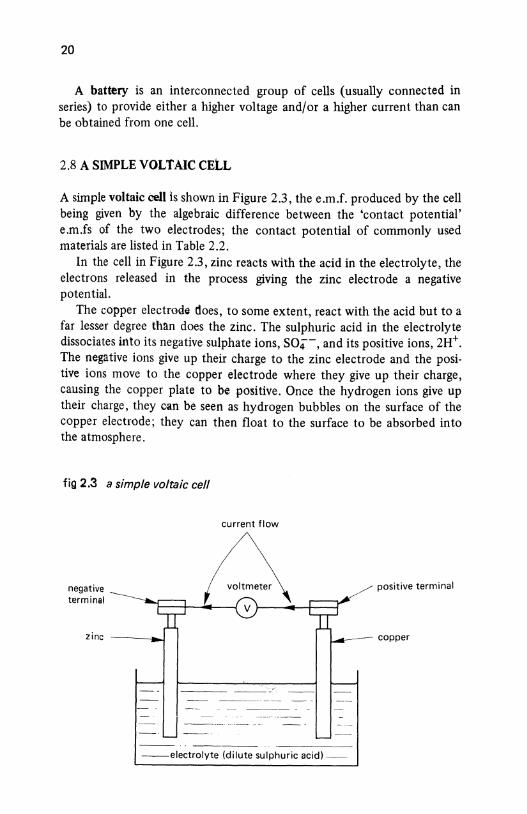
20
A battery is an interconnected group of cells (usually connected in series) to provide either a higher voltage and/or a higher current than can be obtained from one cell.
2.8 A SIMPLE VOLTAIC CElL
A simple voltaic cell is shown in Figure 2.3, the e.m.f. produced by the cell being given by the algebraic difference between the 'contact potential' e.m.fs of the two electrodes; the contact potential of commonly used materials are listed in Table 2.2.
In the cell in Figure 2.3, zinc reacts with the acid in the electrolyte, the electrons released in the process giving the zinc electrode a negative potential.
The copper electrode does, to some extent, react with the acid but to a far lesser degree than does the zinc. The sulphuric acid in the electrolyte dissociates into its negative sulphate ions, S04-, and its positive ions, 2H+. The negative ions give up their charge to the zinc electrode and the positive ions move to the copper electrode where they give up their charge, causing the copper plate to be positive. Once the hydrogen ions give up their charge, they can be seen as hydrogen bubbles on the surface of the copper electrode; they can then float to the surface to be absorbed into the atmosphere.
fig 2.3 a simple voltaic cell
negative terminal
current flow
--electrolyte (dilute sulphuric acid)-
positive terminal
copper
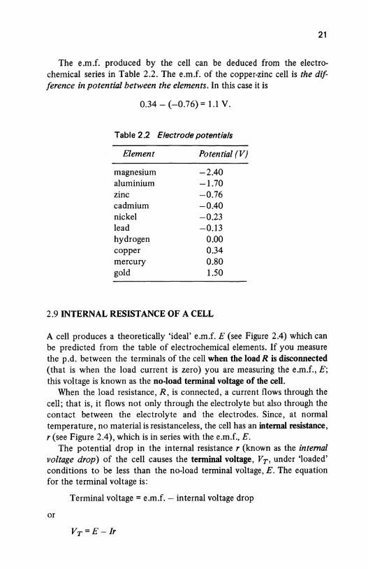
21
The e.m.f. produced by the cell can be deduced from the electrochemical series in Table 2.2. The e.m.f. of the copper-zinc cell is the dif terence in potential between the elements. In this case it is
0.34- (-0.76} = 1.1 v.
Table 2.2 Electrode potentials
Element Potential (V)
magnesium -2.40 aluminium -1.70 zinc -0.76 cadmium -0.40 nickel -0.23 lead -0.13 hydrogen 0.00 copper 0.34 mercury 0.80 gold 1.50
2.9 INTERNAL RESISTANCE OF A CELL
A cell produces a theoretically 'ideal' e.m.f. E (see Figure 2.4) which can be predicted from the table of electrochemical elements. If you measure the p.d. between the terminals of the cell when the load R is disconnected (that is when the load current is zero) you are measuring the e.m.f., E; this voltage is known as the no-load terminal voltage of the cell.
When the load resistance, R, is connected, a current flows through the cell; that is, it flows not only through the electrolyte but also through the contact between the electrolyte and the electrodes. Since, at normal temperature, no material is resistanceless, the cell has an internal resistance, r (see Figure 2.4}, which is in series with the e.m.f., E.
The potential drop in the internal resistance r (known as the internal voltage drop) of the cell causes the terminal voltage, Vr, under 'loaded' conditions to be less than the no-load terminal voltage, E. The equation for the terminal voltage is:
Terminal voltage= e.m.f.- internal voltage drop
or
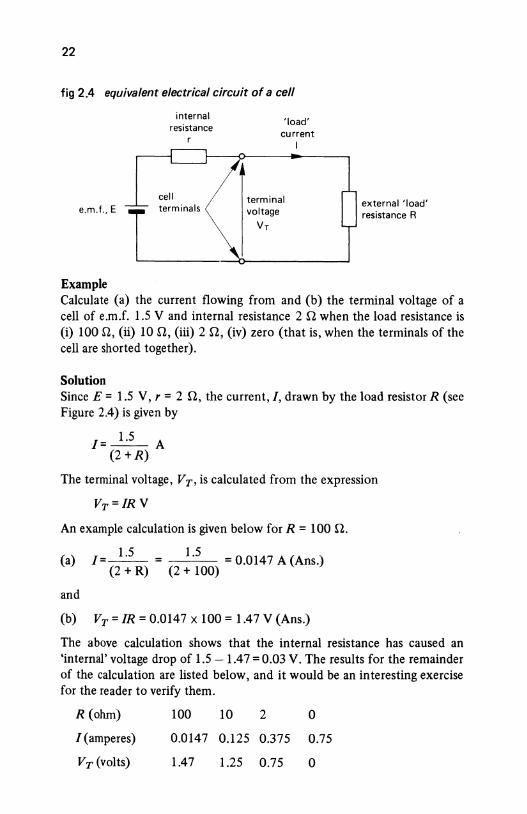
22
fig 2.4 equivalent electrical circuit of a cell
e.m.f., E
Example
internal resistance
cell
c 'load'
current I
terminal voltage
VT
--~------------~
external 'load' resistance R
Calculate (a) the current flowing from and (b) the terminal voltage of a cell of e.m.f. 1.5 V and internal resistance 2 Q when the load resistance is (i) 100 n, (ii) 10 n, (iii) 2 n, (iv) zero (that is, when the terminals of the cell are shorted together).
Solution Since E = 1.5 V, r = 2 n, the current,/, drawn by the load resistor R (see Figure 2.4) is given by
1 = ____!_2_ A (2 +R)
The terminal voltage, VT, is calculated from the expression
VT=/RV
An example calculation is given below for R = 100 il.
(a) I=~ = 1.5 = 0.0147 A (Ans.) (2+R) (2+100)
and
(b) VT = IR = 0.0147 X 100 = 1.47 V (Ans.)
The above calculation shows that the internal resistance has caused an 'internal' voltage drop of 1.5- 1.47 = 0.03 V. The results for the remainder of the calculation are listed below, and it would be an interesting exercise for the reader to verify them.
R (ohm)
!(amperes)
VT (volts)
100 10 2
0.0147 0.125 0.375
1.47 1.25 0.75
0
0.75
0
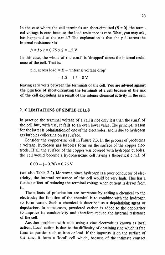
23
In the case where the cell terminals are short-circuited (R = 0), the terminal voltage is zero because the load resistance is zero. What, you may ask, has happened to the e.m.f.? The explanation is that the p.d. across the internal resistance r is
lr =I X r = 0.75 X 2 = 1.5 V
In this case, the whole of the e.m.f. is 'dropped' across the internal resistance of the cell. That is:
p.d. across load = E- 'internal voltage drop'
= 1.5 - 1.5 = 0 v leaving zero volts between the terminals of the cell. You are advised against the practice of short-circuiting the terminals of a cell because of the risk of the cell exploding as a result of the intense chemical activity in the cell.
2.10 LIMITATIONS OF SIMPLE CELLS
In practice the terminal voltage of a cell is not only less than the e.m.f. of the cell but, with use, it falls to an even lower value. The principal reason for the latter is polarisation of one of the electrodes, and is due to hydrogen gas bubbles collecting on its surface.
Consider the copper-zinc cell in Figure 2.3. In the process of producing a voltage, hydrogen gas bubbles form on the surface of the copper electrode. If all the surface of the copper was covered with hydrogen bubbles, the cell would become a hydrogen-zinc cell having a theoretical e.m.f. of
0.00- ( -0.76) = 0.76 v
(see also Table 2.2). Moreover, since hydrogen is a poor conductor of electricity, the internal resistance of the cell would be very high. This has a further effect of reducing the terminal voltage when current is drawn from it.
The effects of polarisation are overcome by adding a chemical to the electrode; the function of the chemical is to combine with the hydrogen to form water. Such a chemical is described as a depolarising agent or depolariser. In some cases, powdered carbon is added to the depolariser to improve its conductivity and therefore reduce the internal resistance of the cell.
Another problem with cells using a zinc electrode is known as local action. Local action is due to the difficulty of obtaining zinc which is free from impurities such as iron or lead. If the impurity is on the surface of the zinc, it form a 'local' cell which, because of the intimate contact
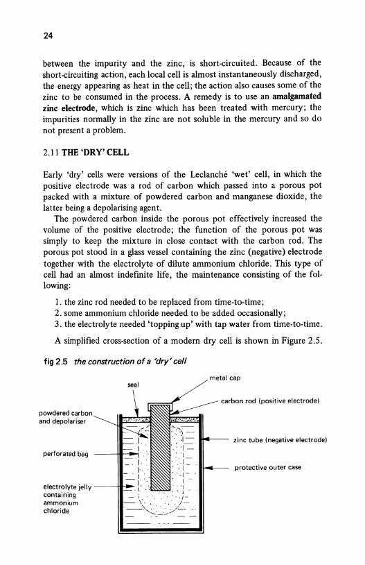
24
between the impurity and the zinc, is short-circuited. Because of the short-circuiting action, each local cell is almost instantaneously discharged, the energy appearing as heat in the cell; the action also causes some of the zinc to be consumed in the process. A remedy is to use an amalgamated zinc electrode, which is zinc which has been treated with mercury; the impurities normally in the zinc are not soluble in the mercury and so do not present a problem.
2.11 THE 'DRY' CELL
Early 'dry' cells were versions of the Leclanche 'wet' cell, in which the positive electrode was a rod of carbon which passed into a porous pot packed with a mixture of powdered carbon and manganese dioxide, the latter being a depolarising agent.
The powdered carbon inside the porous pot effectively increased the volume of the positive electrode; the function of the porous pot was simply to keep the mixture in close contact with the carbon rod. The porous pot stood in a glass vessel containing the zinc (negative) electrode together with the electrolyte of dilute ammonium chloride. This type of cell had an almost indefmite life, the maintenance consisting of the following:
1. the zinc rod needed to be replaced from time-to-time; 2. some ammonium chloride needed to be added occasionally; 3. the electrolyte needed 'topping up' with tap water from time-to-time.
A simplified cross-section of a modern dry cell is shown in Figure 2.5.
fig 2.5 the construction of a 'dry' cell
metal cap seal
carbon rod (positive electrode)
powdered and depolariser .,_
perforated bag
:1- ..,.. __ zinc tube (negative electrode) _: ·)-= :"I
·.·.,-::::. ·I . ·.1--. I -
electrolyte jelly--~-!· . :: ·J
~~n~~~:~~ ___::_~~ ~--·_ ... :_<·~[~-. chloride , _ _-
·- --
protective outer case
25
The positive electrode (the anode) is a carbon rod (as it was in the Leclanche cell), which is in intimate contact with a mixture of powdered carbon and an depolariser which are contained in a perforated bag. The perforations in the bag allow the electrolyte to come into contact with the powdered carbon. The electrolyte is in the form of a jelly, so that the cell can be used in any physical position. The negative electrode (the cathode) is a zinc tube which provides a rigid case for the cell.
Different types of dry cell are manufactured for a range of applications. For example, some cells are specifically designed for use with calculators, some for use with clocks, and others for use with torches, etc. Two of the features allowing a specific performance to be achieved are the number and size of the holes in the perforated bag which holds the depolariser; these affect the rate of discharge of current from the cell.
2.12 OTHER TYPES OF PRIMARY CELL
The zinc chloride cell This is generally similar to the dry cell described in section 2.11, but the electrolyte contains zinc chloride.
The mercury cell The anode in this type of cell is made of zinc, the cathode being a mercury compound, and the electrolyte is sodium or potassium hydroxide. These cells are manufactured in cylindrical and 'button' shapes, and they maintain a fairly constant voltage over their working life. The terminal voltage is typically 1.35-1.4 V per cell.
The silver oxide cell The anode in this cell is made of zinc, the cathode is silver oxide, and the electrolyte is potassium or sodium hydroxide. The button-shape cells give a terminal voltage of about 1.5 V and are widely used in many popular applications including electronic watches, hearing aids and cameras.
The lithium cell This type of cell can provide about ten times more energy than an equivalent size of carbon-zinc cell but, since lithium is a chemically active element, there may be a risk of explosion without warning. Depending on the electrolyte, the e .m .f. is in the range 2.9 to 3. 7 V per cell.
2.13 STORAGE BATTERIES
Rechargable cells are often connected in series to form a storage battery, a car battery being an example; a storage battery is frequently called an ,
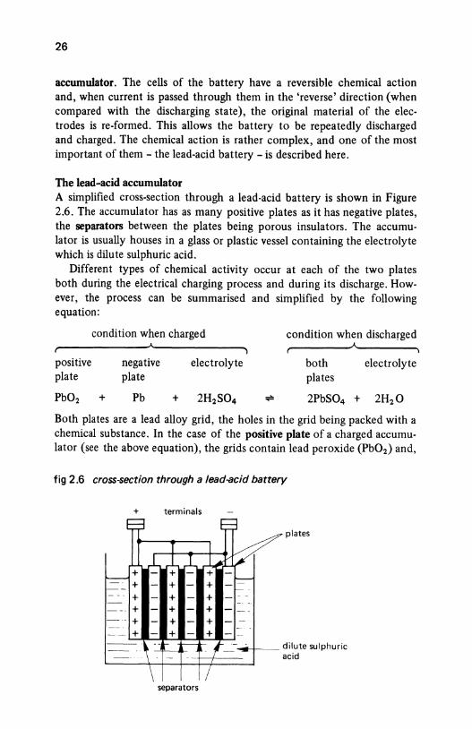
26
accumulator. The cells of the battery have a reversible chemical action and, when current is passed through them in the 'reverse' direction (when compared with the discharging state), the original material of the electrodes is re-formed. This allows the battery to be repeatedly discharged and charged. The chemical action is rather complex, and one of the most important of them - the lead-acid battery -is described here.
The lead-acid accumulator A simplified cross-section through a lead-acid battery is shown in Figure 2.6. The accumulator has as many positive plates as it has negative plates, the separators between the plates being porous insulators. The accumulator is usually houses in a glass or plastic vessel containing the electrolyte which is dilute sulphuric acid.
Different types of chemical activity occur at each of the two plates both during the electrical charging process and during its discharge. However, the process can be summarised and simplified by the following equation:
positive plate
Pb02
condition when charged
+
negative plate
Pb
electrolyte
condition when discha~ged
both plates
electrolyte
2PbS04 + 2H2 0
Both plates are a lead alloy grid, the holes in the grid being packed with a chemical substance. In the case of the positive plate of a charged accumulator (see the above equation), the grids contain lead peroxide (Pb02) and,
fig 2.6 cross-section through a lead-acid battery
+ terminals
plates
-+--dilute sulphuric acid
separators
27
in the case of the negative plate, it is spongy lead (Pb ). During the charging process of the battery, the specific gravity, that is, the strength of the electrolyte gradually increases to a value in the range 1.26-1.28.
The instrument used to test the 'condition' of the charge or discharge of a cell of the battery is known as a hydrometer, and consists of a glass tube containing a calibrated float. When the hydrometer is partly-filled with electrolyte, the level of the calibrated float indicates the density of the electrolyte. Typical values of density are:
Condition
fully charged half charged discharged
Density
1.26 to 1.28 (indicated as 1260 to 1280) 1.25 (indicated as 1250) 1.15-1.2 (indicated as 1150 to 1200)
At the end of the charging process (described below), each cell in the battery has an e.m.f. of about 2.5 V. When the battery has had a period of rest and the electrolyte has diffused throughout each cell, the e.m.f. per cell falls to about 2-2.1 V.
During the early part of the discharge period (say the first hour), the terminal voltage of the battery falls fairly quickly to give an equivalent voltage per cell of about 2 V. During the major part of the discharge period the terminal voltage falls fairly slowly because the electrolyte in the pores of the separators is used up more quickly than fresh electrolyte can flow in. At the end of the discharge period the terminal voltage falls to about 1.8 V per cell, by which time the plates are covered with lead sulphate (PbS04) and the specific gravity has fallen to 1.2 or lower.
During the charging process, the lead sulphate in the paltes is converted into lead peroxide (in the positive plates) and lead (in the negative plates), and the specific gravity gradually increases (indicating the formation of more sulphur acid). The charging process is complete when the lead sulphate is exhausted, and is indicated by a sharp rise in the terminal voltage to give an e.m.f. per cell of about 2.5 V. At this time electrolysis of the water in the electrolyte occurs, causing hydrogen and oxygen gas to be produced at the negative and positive plates, respectively (see section 2.4 for details). When this occurs in a cell, it is said to be gassing.
The nickel-iron (NiFe) alkaline accumulator This is known in the US as the Edison accumulator. This type of battery has a positive plate made of nickel oxide, a negative plate made of iron, the electrolyte being a dilute solution of potassium hydroxide with a small amount of lithium hydroxide.
This type is more robust than the lead-acid accumulator but produces a lower e.m.f. per cell (about 1.2 V). The efficiency of the charge-discharge
28
process is lower than that of the lead-acid accumulator, being about 60 per cent compared with about 75 per cent for the lead-acid type.
The Nickel-Cadmium (NiCd) alkaline accumulator The electrodes and the electrolyte in this accumulator are generally similar to those in the nickel-iron accumulator with the exception that the negative electrode is either made of cadmium or a mixture of iron and cadmium. The average e.m.f. per cell is about 1.2 V; this type of accumulator is widely used in radios, televisions, power tools, etc. Nickel-cadmium batteries are used as 'on-board' power supplies in many computer systems; their function being to maintain a power supply to electronic memories in the event of a power failure.
An interesting feature of the NiCd cell is that the chemical expression, KOH, for the electrolyte does not appear in the charge-discharge equation. This means that the specific gravity of the electrolyte does not change with the state of the charge of the cell; that is to say, the specific gravity of the electrolyte does not give an indication of the state of charge.
Other storage batteries Research not only into specialised electronic applications but also into electric traction {the 'electric' car) has given rise to a number of new accumulators. These include the zinc-chloride cell {about 2.1 V per cell), the lithium-iron sulphide cell {about 1.6 V per cell) and the sodiumsulphur cell. Another interesting cell is the plastic cell which uses a conductive polymer; this cell is claimed to have a much reduced weight and volume combined with a higher capacity than the lead-acid cell.
Capacity of an accumulator The capacity of an accumulator is expressed in terms of the number of ampere-hours (Ah) that may be taken from it during the discharge period. Thus, a 20 Ah battery is capable of supplying a current of 2 A for a period of time given by
time = ampere-hour capacity {Ah) discharge current (A)
20 =- = lOh
2
In addition to the ampere-hour rating, the manufacture specifies the maximum discharge current. If this current is exceeded, the ampere-hour rating of the accumulator is reduced. For example, in the example shown the capacity of the battery may be reduced to, say, 10 Ah if the maximum current is stated as 2 A and the current drawn is 4 A.
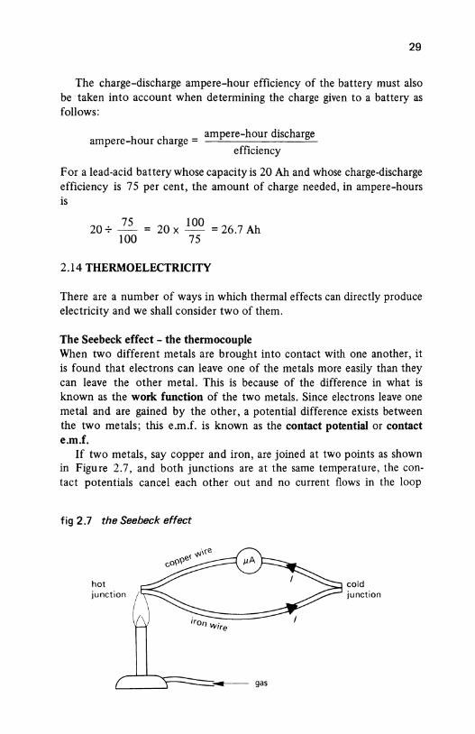
29
The charge-discharge ampere-hour efficiency of the battery must also be taken into account when determining the charge given to a battery as follows:
h h ampere-hour discharge ampere- our c arge =
efficiency
For a lead-acid battery whose capacity is 20 Ah and whose charge-discharge efficiency is 75 per cent, the amount of charge needed, in ampere-hours is
20-;- }.2_ 100
20 X 100 = 26.7 Ah 75
2.14 THERMOELECTRICITY
There are a number of ways in which thermal effects can directly produce electricity and we shall consider two of them.
The Seebeck effect - the thermocouple When two different metals are brought into contact with one another, it is found that electrons can leave one of the metals more easily than they can leave the other metal. This is because of the difference in what is known as the work function of the two metals. Since electrons leave one metal and are gained by the other, a potential difference exists between the two metals; this e.m.f. is known as the contact potential or contact e.m.f.
If two metals, say copper and iron, are joined at two points as shown in Figure 2.7, and both junctions are at the same temperature, the contact potentials cancel each other out and no current flows in the loop
fig 2.7 the Seebeck effect
hot junction
cold junction
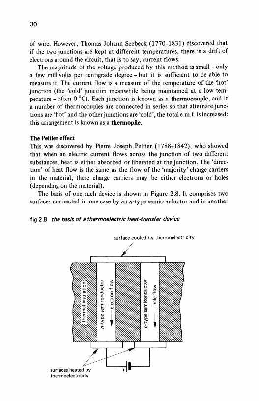
30
of wire. However, Thomas Johann Seebeck (1770-1831) discovered that if the two junctions are kept at different temperatures, there is a drift of electrons around the circuit, that is to say, current flows.
The magnitude of the voltage produced by this method is small - only a few millivolts per centigrade degree - but it is sufficient to be able to measure it. The current flow is a measure of the temperature of the 'hot' junction (the 'cold' junction meanwhile being maintained at a low temperature - often 0 °C}. Each junction is known as a thermocouple, and if a number of thermocouples are connected in series so that alternate junctions are 'hot' and the other junctions are 'cold', the total e.m.f. is increased; this arrangement is known as a thermopile.
The Peltier effect This was discovered by Pierre Joseph Peltier (1788-1842), who showed that when an electric current flows across the junction of two different substances, heat is either absorbed or liberated at the junction. The 'direction' of heat flow is the same as the flow of the 'majority' charge carriers in the material; these charge carriers may be either electrons or holes (depending on the material).
The basis of one such device is shown in Figure 2.8. It comprises two surfaces connected in one case by an n-type semiconductor and in another
fig 2.8 the basis of a thermoelectric heat-transfer device
surface cooled by thermoelectricity
~ 0 0 ...
~ ;;:: u ::J 0 c: "0 ;;:: e c: ., 0 ... u 0 u ., ·e ~ a; .,
~ ~ .,. ., c. > ... Q.
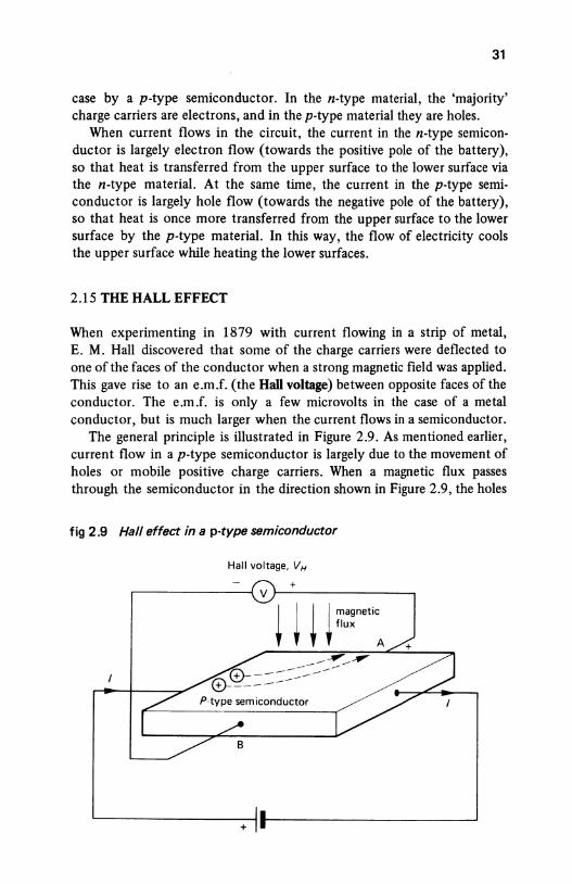
31
case by a p-type semiconductor. In the n-type material, the 'majority' charge carriers are electrons, and in the p-type material they are holes.
When current flows in the circuit, the current in the n-type semiconductor is largely electron flow (towards the positive pole of the battery), so that heat is transferred from the upper surface to the lower surface via the n-type material. At the same time, the current in the p-type semiconductor is largely hole flow (towards the negative pole of the battery), so that heat is once more transferred from the upper surface to the lower surface by the p-type material. In this way, the flow of electricity cools the upper surface while heating the lower surfaces.
2.15 THE HALL EFFECT
When experimenting in 1879 with current flowing in a strip of metal, E. M. Hall discovered that some of the charge carriers were deflected to one of the faces of the conductor when a strong magnetic field was applied. This gave rise to an e.m.f. (the Hall voltage) between opposite faces of the conductor. The e.m.f. is only a few microvolts in the case of a metal conductor, but is much larger when the current flows in a semiconductor.
The general principle is illustrated in Figure 2.9. As mentioned earlier, current flow in a p-type semiconductor is largely due to the movement of holes or mobile positive charge carriers. When a magnetic flux passes through the semiconductor in the direction shown in Figure 2.9, the holes
fig 2.9 Hall effect in a p-type semiconductor
Hall voltage, VH
+ .-------------~ v~--------------~
+
32
experience a force which deflects them towards face A of the semiconductor (the reader should refer to Fleming's Left-Hand Rule in Chapter 9 for details on how to determine the direction of the force). This gives rise to the Hall voltage, VH, which makes face A positive with respect to face B.
If the current flow through the semiconductor is maintained at a constant value, the Hall voltage is proportional to the magnetic flux density passing through the semiconductor.
One application of the Hall effect is the measurement of magnetic fields; instruments used for this purpose are known as magnetometers. Another application is to contactless keys on a computer keyboard (or any keyboard for that matter); the semiconductor element is fixed to the frame of the keyboard and the magnet is mounted in the movable keypad. When the key is pressed, the magnet is moved down to the semiconductor, the resulting Hall voltage being amplified and transmitted to the computer.
2.16 THE PIEZOELECTRIC EFFECT
Certain crystals and semiconductors produce an e.m.f. between two opposite faces when the mechanical pressure on them is either increased or reduced (the polarity of the e.m.f. is reversed when the pressure changes from an increase to a decrease). This e.m.f. is known as the piezoelectric e.m.f.
This effect is used in a number of devices including semiconductor strain gauges and crystal pick-ups for gramophones. As the mechanical pressure on the crystal is altered, a varying voltage which is related to the pressure is produced by the crystal. The voltage can be as small as a fraction of a volt or as large as several thousand volts depending on the crystal material and on the pressure. A very high voltage is produced by the material lead zirconate titanate, which is used in ignition systems for gas ovens and gas fires.
The piezoelectric effect is reversible, and if an alternating voltage is applied between two opposite faces of the crystal, it vibrates in a direction at right-angles to the applied electric field. If the correct frequency of voltage is applied, the crystal resonates in sympathy with the alternating voltage. This is the principle of crystal-controlled watches which keep an accurate time to within a few seconds a year.
2.17 THE PHOTOVOLTAIC CELL OR SOLAR CELL
A photovoltaic cell generates an e.m.f. when light falls onto it. Several forms of photovoltaic cell exist, one of the earliest types being the selenium photovoltaic cell in which a layer of selenium is deposited on iron, and any
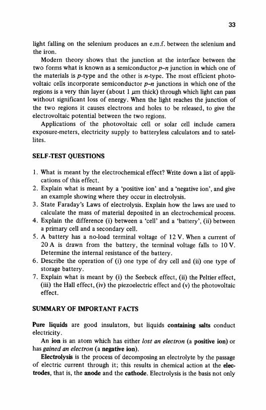
33
light falling on the selenium produces an e.m.f. between the selenium and the iron.
Modern theory shows that the junction at the interface between the two forms what is known as a semiconductor p-n junction in which one of the materials is p-type and the other is n-type. The most efficient photovoltaic cells incorporate semiconductor p-n junctions in which one of the regions is a very thin layer (about 1 J.Lm thick) through which light can pass without significant loss of energy. When the light reaches the junction of the two regions it causes electrons and holes to be released, to give the electrovoltaic potential between the two regions.
Applications of the photovoltaic cell or solar cell include camera exposure-meters, electricity supply to batteryless calculators and to satellites.
SELF -TEST QUESTIONS
1. What is meant by the electrochemical effect? Write down a list of applications of this effect.
2. Explain what is meant by a 'positive ion' and a 'negative ion', and give an example showing where they occur in electrolysis.
3. State Faraday's Laws of electrolysis. Explain how the laws are used to calculate the mass of material deposited in an electrochemical process.
4. Explain the difference (i) between a 'cell' and a 'battery', (ii) between a primary cell and a secondary cell.
5. A battery has a no-load terminal voltage of 12 V. When a current of 20 A is drawn from the battery, the terminal voltage falls to 10 V. Determine the internal resistance of the battery.
6. Describe the operation of (i) one type of dry cell and (ii) one type of storage battery.
7. Explain what is meant by (i) the Seebeck effect, (ii) the Peltier effect, (iii) the Hall effect, (iv) the piezoelectric effect and (v) the photovoltaic effect.
SUMMARY OF IMPORTANT FACTS
Pure liquids are good insulators, but liquids containing salts conduct electricity.
An ion is an atom which has either lost an electron (a positive ion) or has gained an electron (a negative ion).
Electrolysis is the process of decomposing an electrolyte by the passage of electric current through it; this results in chemical action at the electrodes, that is, the anode and the cathode. Electrolysis is the basis not only
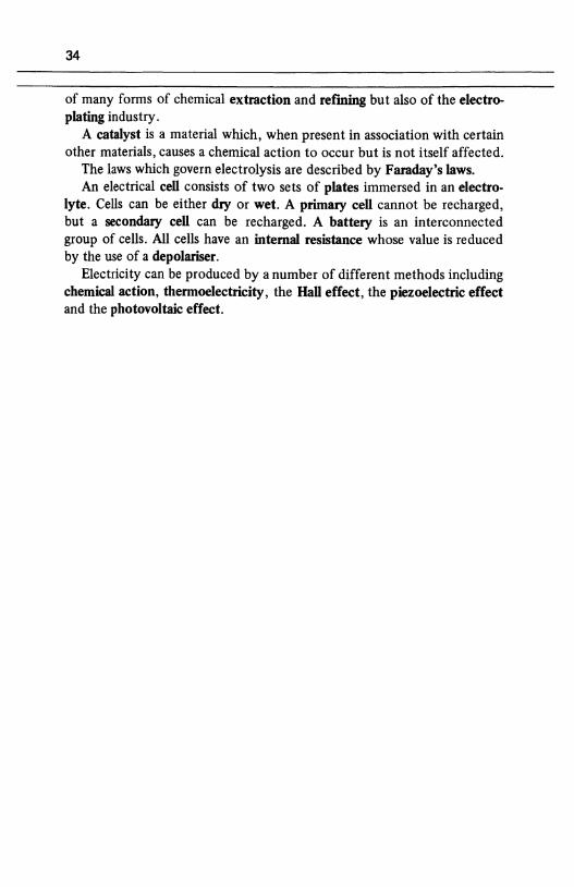
34
of many forms of chemical extraction and ref"ming but also of the electroplating industry.
A catalyst is a material which, when present in association with certain other materials, causes a chemical action to occur but is not itself affected.
The laws which govern electrolysis are described by Faraday's laws. An electrical cell consists of two sets of plates immersed in an electro
lyte. Cells can be either dry or wet. A primary cell cannot be recharged, but a secondary cell can be recharged. A battery is an interconnected group of cells. All cells have an internal resistance whose value is reduced by the use of a depolariser.
Electricity can be produced by a number of different methods including chemical action, thermoelectricity, the Hall effect, the piezoelectric effect and the photovoltaic effect.
CHAPTER 3 35
RESISTORS AND ELECTRICAL CIRCUITS
3.1 RESISTOR TYPES
A resistor is an element whose primary function is to limit the flow of electrical current in a circuit. A resistor is manufactured either in the form of a ftxed resistor or a variable resistor, the resistance of the latter being alterable either manually or electrically. Many methods are employed for the construction of both ftxed and variable resistors, the more important types being described in this chapter.
3.2 FIXED RESISTORS
Carbon composition resistors or carbon resistors The resistive element of this type is manufactured from a mixture of finely ground carbon compound and a non-conducting material such as a ceramic powder. The material is moulded into the required shape (cylindrical in Figure 3.1) and each end is sprayed with metal to which a wire is connected (alternatively, metal end-caps are pressed onto the resistor).
fig 3.1 a carbon composition resistor
insulating material sheath
I I
I i
! I I carbon composition I
wire connection _________ __j
36
fig 3.2 a film resistor
insulating sheath resistive film
spiral groove
/ wire connections
Film resistors The resistive element is a thin film of resistive material which is deposited on an insulating 'former (see Figure 3 .2). The resistance of the resistor is increased to the desired value at the manufacturing stage by cutting a helical groove in the film (thereby increasing the length of the resistive path). There are three popular types of film resistor, namely carbon film (or cracked carbon resistors), metal oxide film resistors and metal film resistors.
A carbon film resistor is formed by depositing a thin film of carbon on an insulating rod. This type of resistor is subject to damage by atmospheric pollution, and is protected by several layers of lacquer or plastic film. Metal oxide film resistors (also known as oxide film resistors) comprise a tin-oxide film deposited on a ceramic former; this type of resistor can be run at a higher temperature than can a carbon film resistor. A metal film resistor is formed by evaporating a nickel-chromium alloy onto a ceramic substrate.
A form of resistor known as a thick film resistor or cermet resistor is manufacturted by depositing a 'thick' film (about 100 times thicker than on a carbon film resistor) of a mixture of a ceramic and metal (which is abbreviated to cermet) on to a ceramic foundation or substrate. Yet another type of resistor known as a thin film resistor is produced by evaporating a thin film of either nickel-chromium or nickel-cobalt onto an insulating substrate; alternatively, the thin film may be of tantalum doped with aluminium.
Wirewound resistors This type is produced by winding a ceramic former with wire made from an alloy of nickel and cobalt, as shown in Figure 3.3. These materials have
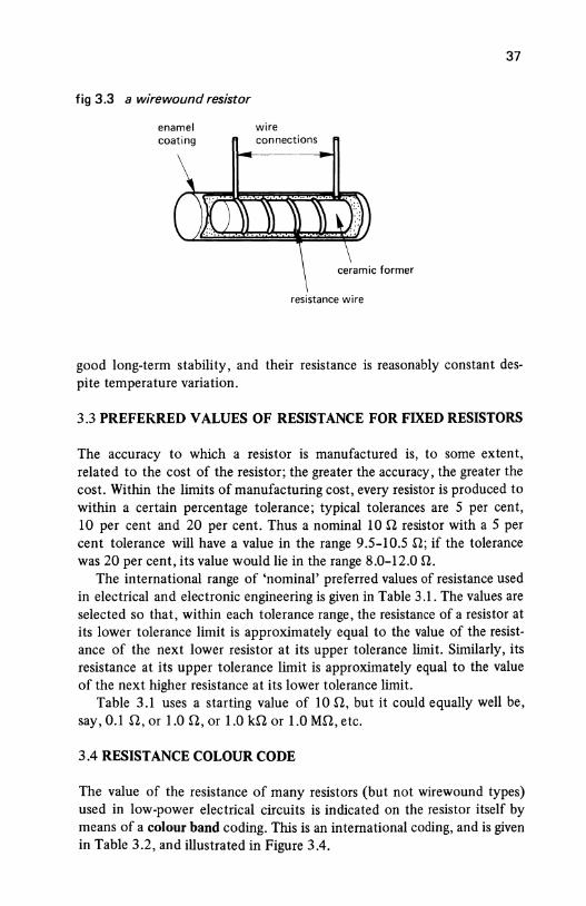
fig 3.3 a wirewound resistor
enamel coating
wire connections
resistance wire
37
good long-term stability, and their resistance is reasonably constant despite temperature variation.
3.3 PREFERRED VALUES OF RESISTANCE FOR FIXED RESISTORS
The accuracy to which a resistor is manufactured is, to some extent, related to the cost of the resistor; the greater the accuracy, the greater the cost. Within the limits of manufacturing cost, every resistor is produced to within a certain percentage tolerance; typical tolerances are 5 per cent, 10 per cent and 20 per cent. Thus a nominal 10 n resistor with a 5 per cent tolerance will have a value in the range 9.5-10.5 n; if the tolerance was 20 per cent, its value would lie in the range 8.0-12.0 n.
The international range of 'nominal' preferred values of resistance used in electrical and electronic engineering is given in Table 3.1. The values are selected so that, within each tolerance range, the resistance of a resistor at its lower tolerance limit is approximately equal to the value of the resistance of the next lower resistor at its upper tolerance limit. Similarly, its resistance at its upper tolerance limit is approximately equal to the value of the next higher resistance at its lower tolerance limit.
Table 3.1 uses a starting value of 10 n, but it could equally well be, say, 0.1 n, or 1.0 n, or 1.0 kn or 1.0 Mn, etc.
3.4 RESISTANCE COLOUR CODE
The value of the resistance of many resistors (but not wirewound types) used in low-power electrical circuits is indicated on the resistor itself by means of a colour band coding. This is an international coding, and is given in Table 3.2, and illustrated in Figure 3.4.
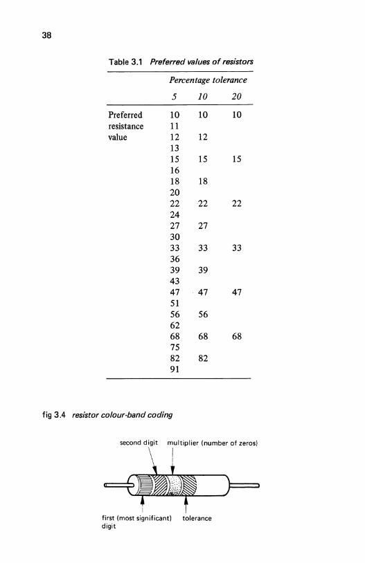
38
Table 3.1 Preferred values of resistors
Percentage tolerance
5 10 20
Preferred 10 10 10 resistance 11 value 12 12
13 15 15 15 16 18 18 20 22 22 22 24 27 27 30 33 33 33 36 39 39 43 47 . 47 47 51 56 56 62 68 68 68 75 82 82 91
fig 3.4 resistor colour-band coding
second digit multiplier (number of zeros)
first (most significant) tolerance digit
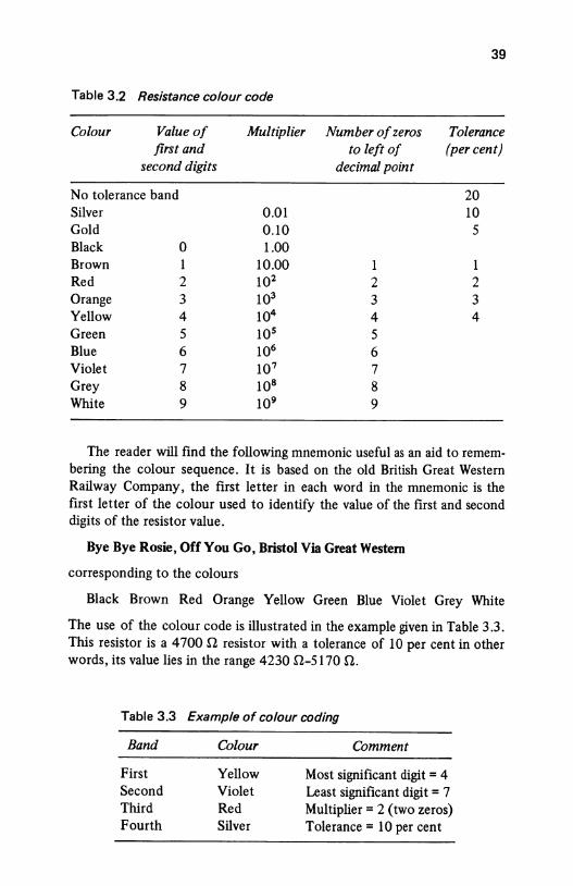
39
Table 3.2 Resistance colour code
Colour Value of Multiplier Number of zeros Tolerance first and to left of (per cent)
second digits decimal point
No tolerance band 20 Silver O.Ql 10 Gold 0.10 5 Black 0 1.00 Brown 1 10.00 1 1 Red 2 102 2 2 Orange 3 103 3 3 Yellow 4 104 4 4 Green 5 105 5 Blue 6 106 6 Violet 7 107 7 Grey 8 108 8 White 9 109 9
The reader will find the following mnemonic useful as an aid to remem· bering the colour sequence. It is based on the old British Great Western Railway Company, the first letter in each word in the mnemonic is the first letter of the colour used to identify the value of the first and second digits of the resistor value.
Bye Bye Rosie, Off You Go, Bristol Via Great Western
corresponding to the colours
Black Brown Red Orange Yellow Green Blue Violet Grey White
The use of the colour code is illustrated in the example given in Table 3.3. This resistor is a 4 700 n resistor with a tolerance of 10 per cent in other words, its value lies in the range 4230 il-5170 n.
Table 3.3 Example of colour coding
Band
First Second Third Fourth
Colour
Yellow Violet Red Silver
Comment
Most significant digit= 4 Least significant digit= 7 Multiplier= 2 (two zeros) Tolerance= 10 per cent
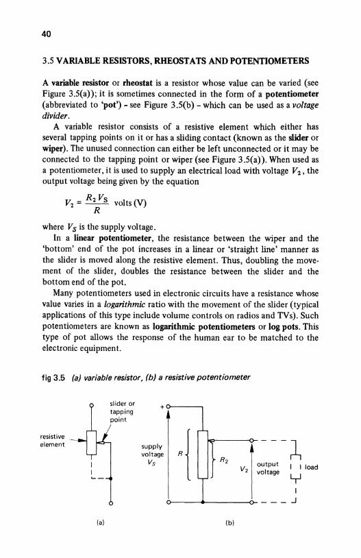
40
3.5 VARIABLE RESISTORS, RHEOSTATS AND POTENTIOMETERS
A variable resistor or rheostat is a resistor whose value can be varied (see Figure 3.5(a)); it is sometimes connected in the form of a potentiometer (abbreviated to 'pot')- see Figure 3.5(b)- which can be used as a voltage divider.
A variable resistor consists of a resistive element which either has several tapping points on it or has a sliding contact (known as the slider or wiper). The unused connection can either be left unconnected or it may be connected to the tapping point or wiper (see Figure 3.5(a)). When used as a potentiometer, it is used to supply an electrical load with voltage V2 , the output voltage being given by the equation
V2 = R2 Vs volts (V) R
where Vs is the supply voltage. In a linear potentiometer, the resistance between the wiper and the
'bottom' end of the pot increases in a linear or 'straight line' manner as the slider is moved along the resistive element. Thus, doubling the movement of the slider, doubles the resistance between the slider and the bottom end of the pot.
Many potentiometers used in electronic circuits have a resistance whose value varies in a logarithmic ratio with the movement of the slider (typical applications of this type include volume controls on radios and TVs). Such potentiometers are known as logarithmic potentiometers or log pots. This type of pot allows the response of the human ear to be matched to the electronic equipment.
fig 3.5 (a) variable resistor, (b) a resistive potentiometer
slider or tapping
+
point
resistive
·{ element supply --- ~
voltage R2 Vs l ·"~"' I I load v2 voltage y
T I ___ .J
(a) (b)
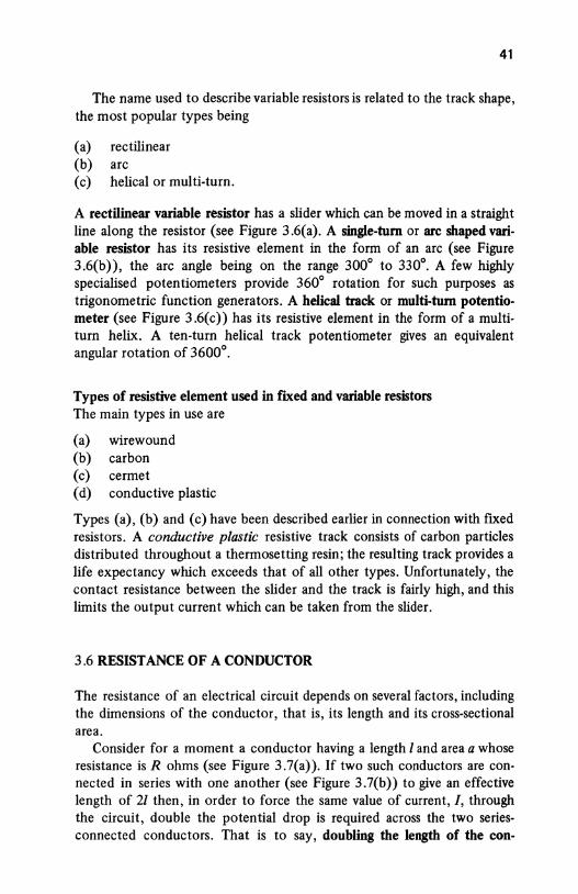
41
The name used to describe variable resistors is related to the track shape, the most popular types being
(a) rectilinear (b) arc (c) helical or multi-turn.
A rectilinear variable resistor has a slider which can be moved in a straight line along the resistor (see Figure 3.6(a). A single-tum or arc shaped variable resistor has its resistive element in the form of an arc (see Figure 3.6(b)), the arc angle being on the range 300° to 330°. A few highly specialised potentiometers provide 360° rotation for such purposes as trigonometric function generators. A helical track or multi-tum potentiometer (see Figure 3 .6( c)) has its resistive element in the form of a multiturn helix. A ten-turn helical track potentiometer gives an equivalent angular rotation of 3600°.
Types of resistive element used in iJXed and variable resistors The main types in use are
(a) wirewound (b) carbon (c) cermet (d) conductive plastic
Types (a), (b) and (c) have been described earlier in connection with fiXed resistors. A conductive plastic resistive track consists of carbon particles distributed throughout a thermosetting resin; the resulting track provides a life expectancy which exceeds that of all other types. Unfortunately, the contact resistance between the slider and the track is fairly high, and this limits the output current which can be taken from the slider.
3.6 RESISTANCE OF A CONDUCTOR
The resistance of an electrical circuit depends on several factors, including the dimensions of the conductor, that is, its length and its cross-sectional area.
Consider for a moment a conductor having a length I and area a whose resistance is R ohms (see Figure 3.7(a)). If two such conductors are connected in series with one another (see Figure 3.7(b)) to give an effective length of 21 then, in order to force the same value of current, /, through the circuit, double the potential drop is required across the two seriesconnected conductors. That is to say, doubling the length of the con-
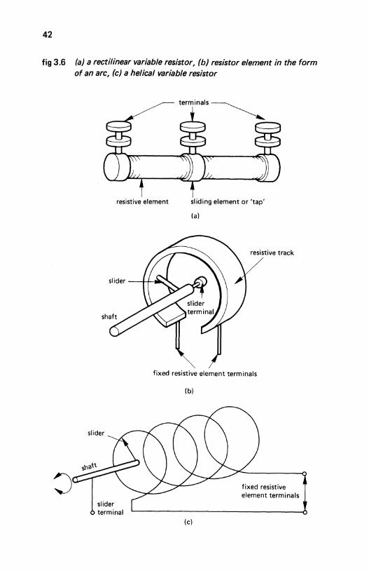
42
fig 3.6 (a) a rectilinear variable resistor, (b) resistor element in the form of an arc, (c) a helical variable resistor
terminals~
resistive element sliding element or 'tap'
(a)
resistive track
fixed resistive element terminals
slider
slider terminal
(b)
(c)
fixed resistive element terminals
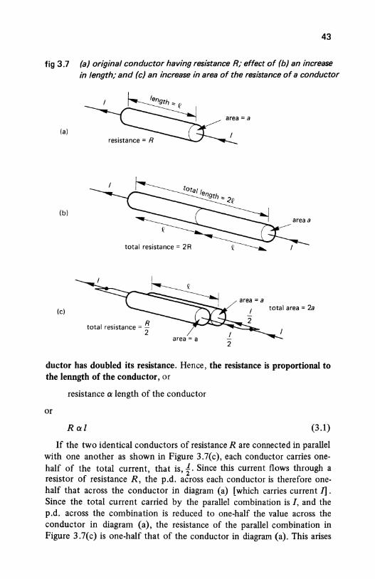
43
fig 3.7 (a) original conductor having resistance R; effect of (b) an increase in length; and (c) an increase in area of the resistance of a conductor
(a)
(b)
area= a (c) total area = 2a
total resistance= ~
2
ductor has doubled its resistance. Hence, the resistance is proportional to the lenngth of the conductor, or
resistance o: length of the conductor
or
R o:l (3.1)
If the two identical conductors of resistance R are connected in parallel with one another as shown in Figure 3.7(c), each conductor carries onehalf of the total current, that is, 1· Since this current flows through a resistor of resistance R, the p.d. across each conductor is therefore onehalf that across the conductor in diagram (a) [which carries current I]. Since the total current carried by the parallel combination is I, and the p.d. across the combination is reduced to one-half the value across the conductor in diagram (a), the resistance of the parallel combination in Figure 3.7(c) is one-half that of the conductor in diagram (a). This arises
44
because the total area of the conducting path has doubled; that is, the resistance is inversely proportional to the area, a, of the conductor, or
or
resistance a
1 R a-
a
area
Combining eqns (3.1) and (3.2) gives
1 Ra-
a
(3.2)
(3.3)
The proportionality sign in eqn (3 .3) is converted into an equals sign simply by inserting a 'constant of proportionality' into the equation. This constant is known as the resistivity of the conductor material; resistivity is given the Greek symbol p (pronounced rho). Hence
R=l!!n a
The dimensions of resistivity are worked out below. From eqn (3.4)
Ra
hence
p= -1
Ra dimensions of p = dimensions of 1
no. of ohms x area
length
no. of ohms x [length x length]
length
(3.4)
= no. of ohms x length or ohm metres (Q m)
Typical values for the resistivity of materials used in electrical engineering are given in Table 3.4. The materials manganin and constantan have high resistivity combined with a low temperature coefficient of resistance (see section 3.8), and are widely used in ammeter shunts and in voltmeter multiplier resistors (see also Chapter 4). Nichrome has a very high resistivity and is used as a conductor in heating elements in fires and ovens, and operates satisfactorily at temperatures up to 1100 °C. The reader should
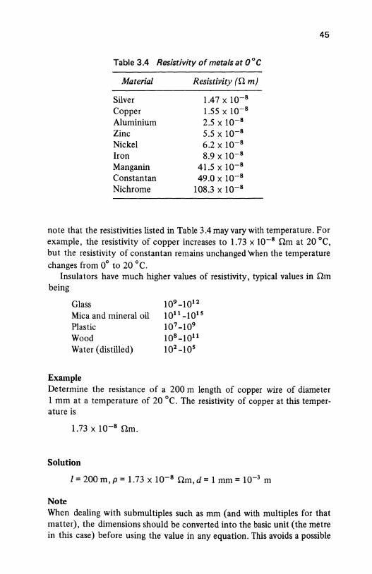
Table 3.4 Resistivity of metals at 0 ° C
Material
Silver Copper Aluminium Zinc Nickel Iron Manganin Constantan Nichrome
Resistivity (!J. m)
1.47 X 10⁻⁸
1.55 X 10⁻⁸
2.5 X 10⁻⁸
5.5 X 10⁻⁸
6.2 X 10⁻⁸
8.9 X 10⁻⁸
41.5 X 10⁻⁸
49.0 X 10⁻⁸
108.3 X 10⁻⁸
45
note that the resistivities listed in Table 3.4 may vary with temperature. For example, the resistivity of copper increases to 1.73 x 10⁻⁸ !J.m at 20 °C, but the resistivity of constantan remains unchanged when the temperature changes from 0° to 20 °C.
Insulators have much higher values of resistivity, typical values in !J.m being
Glass Mica and mineral oil Plastic Wood Water (distilled)
Example
109-1012 1011-1015 107 -109 108-1011 102 -105
Determine the resistance of a 200 m length of copper wire of diameter 1 mm at a temperature of 20 °C. The resistivity of copper at this temperature is
1.73 x 10⁻⁸ !J.m.
Solution
l =200m, p = 1.73 x 10⁻⁸ !J.m, d = 1 mm = 10-3 m
Note When dealing with submultiples such as mm (and with multiples for that matter), the dimensions should be converted into the basic unit (the metre in this case) before using the value in any equation. This avoids a possible
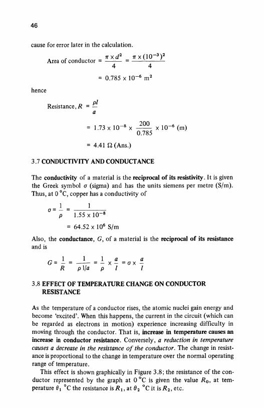
46
cause for error later in the calculation.
hence
1T X d 2 1T X (10-3 ) 2 Area of conductor = -- = _ _o_ _ _:_
Resistance, R = P1 a
4 4
= 0.785 X 10⁻⁶ m 2
= 1.73 X 10-8 X 200 X 10-6 (m) 0.785
= 4.41 il (Ans.)
3.7 CONDUCTIVITY AND CONDUCTANCE
The conductivity of a rna terial is the reciprocal of its resistivity. It is given the Greek symbol a (sigma) and has the units siemens per metre (S/m). Thus, at 0 °C, copper has a conductivity of
- 1 - 1 a- - - -----o-
P 1.55 X 10-8
= 64.52 x 10⁶ S/m
Also, the conductance, G, of a material is the reciprocal of its resistance and is
- 1 -G---R
1 1
p 1/a p
a X- =a X
1 a 1
3.8 EFFECT OF TEMPERATURE CHANGE ON CONDUCTOR RESISTANCE
As the temperature of a conductor rises, the atomic nuclei gain energy and become 'excited'. When this happens, the current in the circuit (which can be regarded as electrons in motion) experience increasing difficulty in moving through the conductor. That is, increase in temperature causes an increase in conductor resistance. Conversely, a reduction in temperature causes a decrease in the resistance of the conductor. The change in resistance is proportional to the change in temperature over the normal operating range of temperature.
This effect is shown graphically in Figure 3.8; the resistance of the conductor represented by the graph at 0 °C is given the value R 0 , at temperature 81 °C the resistance is R 1 , at 02 °C it is R 2 , etc.
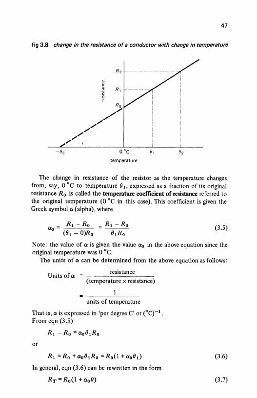
47
fig 3.8 change in the resistance of a conductor with change in temperature
QJ u c r= R, "' ·v; ~
temperature
e,
The change in resistance of the resistor as the temperature changes from, say, 0 °C to temperature 01 , expressed as a fraction of its original resistance R 0 is called the temperature coefficient of resistance referred to the original temperature (0 °C in this case). This coefficient is given the Greek symbol a (alpha), where
(3.5)
Note: the value of a is given the value ao in the above equation since the original temperature was 0 °C.
The units of a can be determined from the above equation as follows:
resistance Units of a = -------
(temperature x resistance)
units of temperature
That is, a is expressed in 'per degree C' or CC)-1 .
From eqn (3 .5)
Rt - R 0 = aoOtRo
or
Rt =Ro +aoOtRo =R0 (1 +a0 0.)
In general, eqn (3 .6) can be rewritten in the form
Rr = Ro(l + a0 0)
(3.6)
(3.7)
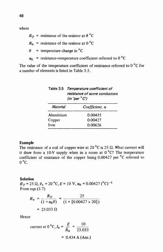
48
where
RT = resistance of the resistor at(} °C
R 0 resistance of the resistor at 0 °C
(} = temperature change in °C
ao resistance-temperature coefficient referred to 0 °C
The value of the temperature coefficient of resistance referred to 0 °C for a number of elements is listed in Table 3.5.
Example
Table 3.5 Temperature coefficient of resistance of some conductors (in 'per ° C')
Material
Aluminium Copper Iron
Coefficient, ex
0.00435 0.00427 0.00626
The resistance of a coil of copper wire at 20 °C is 25 n. What current will it draw from a 10-V supply when in a room at 0 °C? The temperature coefficient of resistance of the copper being 0.00427 per °C referred to 0 °C.
Solution RT = 25 n, 01 = 20 °C, E = 10 v, exo = o.oo427 (0 C)-1
From eqn (3.7)
_ RT 25 Ro -----
(1 + cx0 0) (1 + (0.00427 X 20])
= 23.033 n Hence
o E current at 0 C,/0 = -
Ro
10 ----
23.033
= 0.434 A (Ans.)

49
3.9 SUPERCONDUCTIVITY
It is shown in Figure 3.8 that if the temperature of a conductor is progressively reduced, its resistance would reach zero at some temperature -83 •
However, scientific tests have shown that, for a limited range of conductors, the resistance falls to a value which is too small to be measured at a temperature within 10° of absolute zero temperature ( -273 °C)- see Figure 3.9. Included in these are tin (within 3.7° of absolute zero), mercury (within 4.1 °) and lead (within 7.2°).
3.10 TEMPERATURE EFFECTS ON INSULATORS AND ON SEMICONDUCTORS
Insulators and semiconductors behave in a different way when the temperature increases, because their resistivity decreases. That is: the resistance of an insulator and of a semiconductor decreases with temperature increase, (their resistance-temperature coefficient is negative!). This feature can be used to advantage as the following example shows.
One example of this effect occurs in a thermistor, which is a THERMally sensitive resiSTOR whose resistance alters with temperature; a negative temperature coefficient (n.t.c.) thermistor is one whose resistance reduces with increase in temperature. A thermistor is used in the cooling-water temperature-measuring circuit of a car or lorry; it is inserted in the cooling water and connected in series with the battery and temperature gauge. As the water temperature rises, the resistance of the n.t.c. thermistor falls and
fig 3.9 superconductivity
temperature
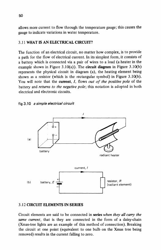
50
allows more current to flow through the temperature gauge; this causes the gauge to indicate variations in water temperature.
3.11 WHAT IS AN ELECTRICAL CIRCUIT?
The function of an electrical circuit, no matter how complex, is to provide a path for the flow of electrical current. In its simplest form, it consists of a battery which is connected via a pair of wires to a load (a heater in the example shown in Figure 3.10(a)). The circuit diagram in Figure 3.10(b) represents the physical circuit in diagram (a), the heating element being shown as a resistor (which is the rectangular symbol) in Figure 3.10(b). You will note that the current, /, flows out of the positive pole of the battery and returns to the negative pole; this notation is adopted in both electrical and electronic circuits.
fig 3.10 a simple electrical circuit
(a)
battery radiant heater
current, I
(b)
'""'Y E tL,-____ .. ____ __.JQ ;;:~~:~; ~•m'"'' 3.12 CIRCUIT ELEMENTS IN SERIES
Circuit elements are said to be connected in series when they all carry the same current, that is they are connected in the form of a daisy-chain (Xmas-tree lights are an example of this method of connection). Breaking the circuit at one point (equivalent to one bulb on the Xmas tree being removed) results in the current falling to zero.
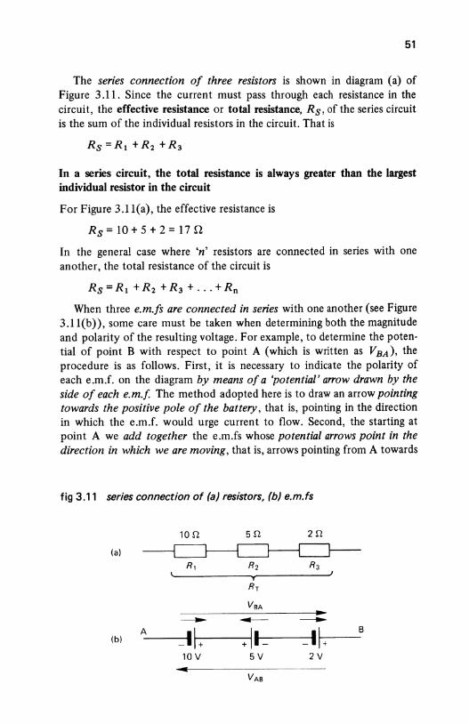
51
The series connection of three resistors is shown in diagram (a) of Figure 3.11. Since the current must pass through each resistance in the circuit, the effective resistance or total resistance, Rs, of the series circuit is the sum of the individual resistors in the circuit. That is
In a series circuit, the total resistance is always greater than the largest individual resistor in the circuit
For Figure 3.11(a), the effective resistance is
R8 =10+5+2=17Q
In the general case where 'n' resistors are connected in series with one another, the total resistance of the circuit is
Rs = R1 + R2 + R3 + ... + Rn
When three e.m.fs are connected in series with one another (see Figure 3.11(b)), some care must be taken when determining both the magnitude and polarity of the resulting voltage. For example, to determine the potential of point B with respect to point A (which is written as VBA), the procedure is as follows. First, it is necessary to indicate the polarity of each e.m.f. on the diagram by means of a 'potential' a"ow drawn by the side of each e.m.f. The method adopted here is to draw an arrow pointing towards the positive pole of the battery, that is, pointing in the direction in which the e.m.f. would urge current to flow. Second, the starting at point A we add together the e.m.fs whose potential a"ows point in the direction in which we are moving, that is, arrows pointing from A towards
fig 3.11 series connection of (a) resistors, (b) e.m.fs
10.n sn 2n
(a)
---- ---- ----A _l~---1 + -------1+ 11- -·~ (b)
10 V 5V 2V
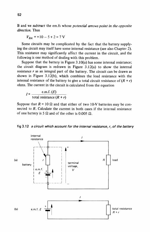
52
B and we subtract the em.fs whose potential a"ows point in the opposite direction. Thus
VBA = + 10- 5 + 2 = 7 V
Some circuits may be complicated by the fact that the battery supplying the circuit may itself have some internal resistance (see also Chapter 2). This resistance may significantly affect the current in the circuit, and the following is one method of dealing with this problem.
Suppose that the battery in Figure 3.10(a) has some internal resistance; the circuit diagram is redrawn in Figure 3.12(a) to show the internal resistance r as an integral part of the battery. The circuit can be drawn as shown in Figure 3.12(b), which combines the load resistance with the internal resistance of the battery to give a total circuit resistance of (R + r) ohms. The current in the circuit is calculated from the equation
e.m.f. (E) [=----~--~----
total resistance (R + r)
Suppose that R = 10 Q and that either of two 10-V batteries may be connected toR. Calculate the current in both cases if the internal resistance of one battery is 5 nand of the other is 0.005 n.
fig 3.12 a circuit which account for the internal resistance, r, of the battery
internal resistance
,- ---, + I I I I I I
(a) I I R load
battery I I terminal I I voltage, I e.m.f.
t I v
I E I I I I I L ____ ____ _j
(b)
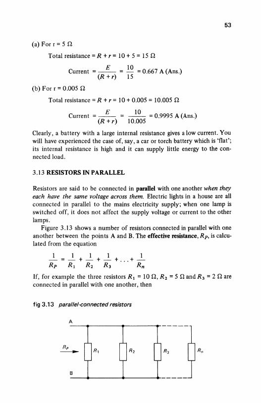
53
(a) For r = 5 rl
Total resistance= R + r = 10 + 5 = 15 rl
E 10 Current = -- = - = 0.667 A (Ans.)
(R +r) 15
(b) For r = 0.005 rl
Total resistance= R + r = 10 + 0.005 = 10.005 rl
E 10 Current = -- = -- = 0.9995 A (Ans.)
(R + r) 10.005
Clearly, a battery with a large internal resistance gives a low current. You will have experienced the case of, say, a car or torch battery which is 'flat'; its internal resistance is high and it can supply little energy to the connected load.
3.13 RESISTORS IN PARALLEL
Resistors are said to be connected in paraUel with one another when they each have the same voltage across them. Electric lights in a house are all connected in parallel to the mains electricity supply; when one lamp is switched off, it does not affect the supply voltage or current to the other lamps.
Figure 3.13 shows a number of resistors connected in parallel with one another between the points A and B. The effective resistance, Rp, is calculated from the equation
1 1 1 1 1 -=-+-+-+ ... +-Rp Rt R2 R3 Rn
If, for example the three resistors R 1 = 10 rl, R 2 = 5 n andR 3 = 2 rl are connected in parallel with one another, then
fig 3.13 parallel-connected resistors
A
Rp ----B
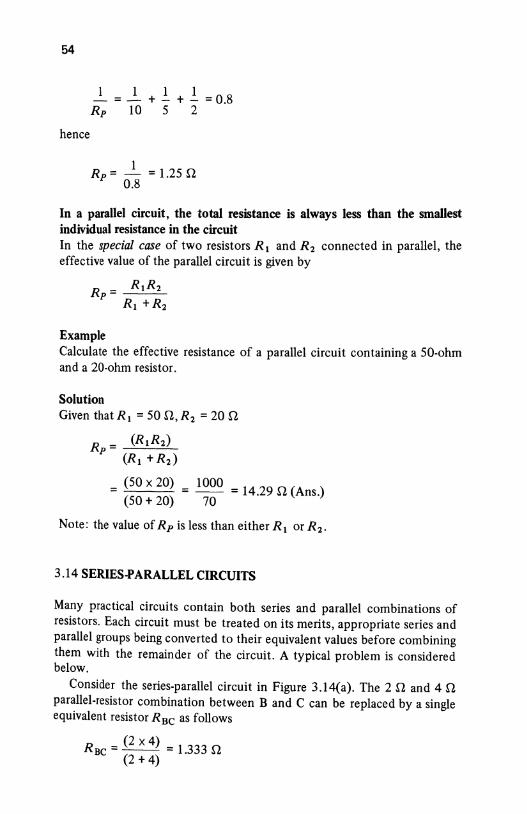
54
hence
1 1 1 1 - = - + - + - = 0.8 Rp 10 5 2
1 Rp=- = 1.25 n
0.8
In a parallel circuit, the total resistance is always less than the smallest individual resistance in the circuit In the special case of two resistors R 1 and R 2 connected in parallel, the effective value of the parallel circuit is given by
R _ R1R2 p-
Rt +R2
Example Calculate the effective resistance of a parallel circuit containing a 50-ohm and a 20-ohm resistor.
Solution Given thatR 1 =50 il,R2 = 20 il
Rp = (R1R2) (Rt + R2)
= (50 X 20) = 1000 = 14.29 il (Ans.) (50+ 20) 70
Note: the value of Rp is less than either R 1 or R 2 .
3.14 SERIES-PARALLEL CIRCUITS
Many practical circuits contain both series and parallel combinations of resistors. Each circuit must be treated on its merits, appropriate series and parallel groups being converted to their equivalent values before combining them with the remainder of the circuit. A typical problem is considered below.
Consider the series-parallel circuit in Figure 3.14{a). The 2 il and 4 il parallel-resistor combination between B and C can be replaced by a single equivalent resistor Rsc as follows
R = (2 X 4) = 1.333 il BC (2 + 4)
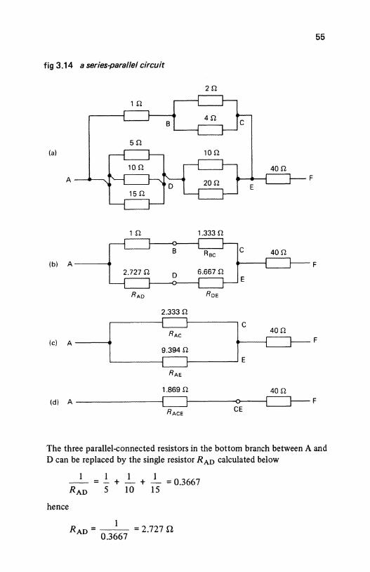
55
fig 3.14 a series-parallel circuit
(a)
F
1fl 1.333fl
(b) A F
RAo Roe
2.333 n c
RAe 40fl
(c) A F 9.394 n
E
RAe
1.869fl 40fl
(d) A F
RAce CE
The three parallel-connected resistors in the bottom branch between A and D can be replaced by the single resistor RAD calculated below
-- + + = 0.3667 RAD 5 10 15
hence
RAD = 1 = 2.727 n
0.3667
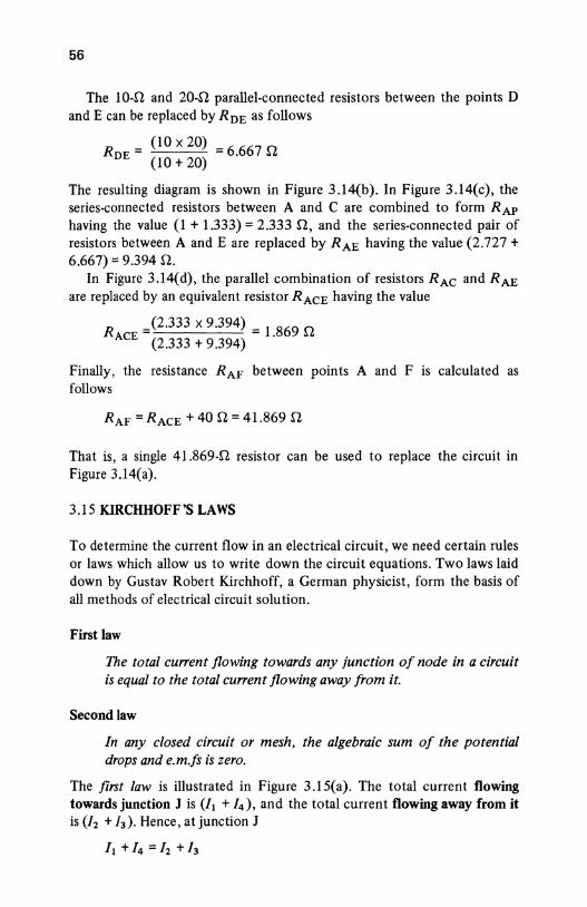
56
The 10-!1 and 20-!1 parallel-connected resistors between the points D and E can be replaced byRnE as follows
R = (10 X 20) = 6.667 [2 DE (10 + 20)
The resulting diagram is shown in Figure 3.14(b). In Figure 3.14(c), the series-connected resistors between A and C are combined to form RAP having the value (1 + 1.333) = 2.333 n, and the series-connected pair of resistors between A and E are replaced by RAE having the value (2.727 + 6.667) = 9.394 n.
In Figure 3.14(d), the parallel combination of resistors RAe and RAE are replaced by an equivalent resistor RAcE having the value
R )2.333 X 9.394) = 1.869 [2
ACE (2.333 + 9.394)
Finally, the resistance RAF between points A and F is calculated as follows
RAF =RAcE+ 40 [2 = 41.869 [2
That is, a single 41.869-n resistor can be used to replace the circuit in Figure 3.14(a).
3.15 KIRCHHOFF'S LAWS
To determine the current flow in an electrical circuit, we need certain rules or laws which allow us to write down the circuit equations. Two laws laid down by Gustav Robert Kirchhoff, a German physicist, form the basis of all methods of electrical circuit solution.
First law
The total cu"ent flowing towards any junction of node in a circuit is equal to the total cu"ent flowing away from it.
Second Jaw
In any closed circuit or mesh, the algebraic sum of the potential drops and e.m.fs is zero.
The first law is illustrated in Figure 3.15(a). The total current flowing towards junction J is (/1 + / 4 ), and the total current flowing away from it is (/2 +h). Hence, at junction J
It + /4 = /2 + /3
57
fig 3.15 (a) Kirchhoff's first law and (b) Kirchhoff's second law
(a)
(b) E,
IR 1
(c)
The second law is illustrated in Figure 3.15(b) and (c). In the closed loop ABCDA (remember, you must always return to the point from which you start in a closed loop), there are two e.m.fs (produced by the cells)
58
and three potential drops ('dropped' across the resistors). In order to write down the equation relating the e.m.fs and p.ds in Figure 3.15(b), it is necessary to add some information as shown in Figure 3.15(c); to do this the following steps must be taken:
1. Draw on the circuit the direction in which the current flows (if this is not known, simply assume a direction of flow [as will be seen later, the assumed direction is unimportant so far as the calculation is concerned]).
2. Draw an e.m.f. arrow by the side of each e.m.f. in the circuit which points towards the positive pole of the cell.
3. Draw a potential drop arrow by the side of each resistor which points towards the more positive terminal of the resistor (Note: the potential arrow always points in the opposite direction to the current flow through the resistor). At the same time, write down the equation of the p.d. across the resistor, that is, /R 1 , IR 2 , etc.
Having completed these steps (see Figure 3.15(c) and starting at any point in the circuit, proceed around the circuit and return to the same point writing down the e.m.fs and p.ds as they are reached. A positive sign is given to any e.m.f. or p.d. if the e.m.f. arrow or potential arrow points in the direction in which you move around the loop; a negative sign is given if the arrow points in the opposite direction. We will now apply these rules to Figure 3.15(b).
First, draw an arrow showing the direction of the current. Since you do not know the value of E 1 and £ 2 , the current is arbitrarily chosen to circulate around the loop in a clockwise direction. The direction in which the current is assumed to flow therefore 'fixes' the direction of the 'potential' arrows associated with the p.d. across each resistor.
In order to write down the circuit equation, we need to proceed around the closed loop ABCDA and write down each e.m.f. and p.d. according to the procedure outlined. We will traverse around the loop in a clockwise direction; starting at point A, the circuit equation is written down according to Kirchhoff's second law as follows.
LoopABCDA
+£1 - IR1 - IR2 - E2 - IR3 = 0
Collecting e.m.fs on the left-hand side of the equation gives
£1 - E2 =IRt + IR2 + IR3 =I(Rt + R2 + R3)
You would find it an interesting exercise to write down the equation for the circuit starting at, say, point C and circulating around the loop in the opposite direction. The resulting equation should be the same as the one
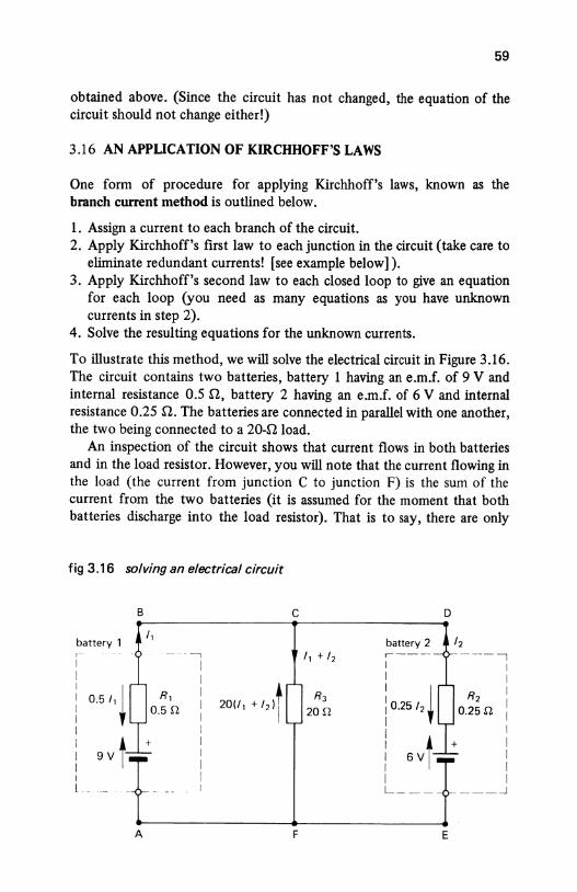
59
obtained above. (Since the circuit has not changed, the equation of the circuit should not change either!)
3.16 AN APPLICATION OF KIRCHHOFF'S LAWS
One form of procedure for applying Kirchhoff's laws, known as the branch current method is outlined below.
1. Assign a current to each branch of the circuit. 2. Apply Kirchhoff's first law to each junction in the circuit (take care to
eliminate redundant currents! [see example below]). 3. Apply Kirchhoff's second law to each closed loop to give an equation
for each loop (you need as many equations as you have unknown currents in step 2).
4. Solve the resulting equations for the unknown currents.
To illustrate this method, we will solve the electrical circuit in Figure 3.16. The circuit contains two batteries, battery 1 having an e.m.f. of 9 V and internal resistance 0.5 n, battery 2 having an e.m.f. of 6 V and internal resistance 0.25 n. The batteries are connected in parallel with one another, the two being connected to a 20-D load.
An inspection of the circuit shows that current flows in both batteries and in the load resistor. However, you will note that the current flowing in the load (the current from junction C to junction F) is the sum of the current from the two batteries (it is assumed for the moment that both batteries discharge into the load resistor). That is to say, there are only
fig 3.16 solving an electrical circuit
B c D
battery 1 ,,
battery 2 /2 r- -- -~1 ,, + /2 ,---- ---, I
I I I I I I I I
0.51, ~ I 20(1, + /2)t i 0.25 /2 ~ I I
I R3 R2
I I I
20r2 o.25n I I I I
9Vt I I 6Vt
I I I I I I I I I I I L ___ ___ _j
A F E
60
two unknown currents, namely / 1 and / 2 (the current in the 20-0 resistor being equal to /1 + /2).
The circuit contains three closed loops, namely ABCFA, ABCDEFA and CDEFC. Any pair of loops can be used to give the equations we need, the first two being chosen in this case.
LoopABCFA The current directions selected are shown in Figure 4.16, and the e.m.f. and p.d. arrows are drawn according to the rules laid down earlier. Starting at point A and proceeding around the loop in the direction ABCF A, the loop equation is
or
9-0.5/1 - 20(/1 + /2) = 0
9 = 20/1 + 0.5/1 + 20/2
= 20.5/1 + 20/2
Loop ABCDEFA
(3.8)
Starting at point A and proceeding around the loop in a clockwise direction gives the equation
9-0.5/1 +0.25/2 -6=0
or
3 = 0.5/1 - 0.25/2
Equations (3.8) and (3.9) are collected together as follows
9 = 20.5/1 + 20/2
3 = 0.5/1 - 0.25/2
(3.9)
(3.8)
(3.9)
To eliminate / 2 from the pair of equations, eqn (3.9) is multiplied by 80 and added to eqn (3.8) as follows
9 = 20.5/1 + 20/2 (3.8)
240 = 40.0/1 - 20/2 80 X (3.9)
Adding these together gives
249 = 60.5/1
hence 249
/ 1 = - = 4.116 A (Ans.) 60.5
61
The value of I2 is calculated by substituting the value of It either into eqn (3.8) or eqn (3.9). We will use eqn (3.9) as follows:
3 = 0.5It - 0.25I2 = (0.5 X 4.116)- 0.25I2
= 2.058 - 0.25I2
hence
0.25I2 = 2.058 - 3 = -0.942
therefore
I 2 = - 0·942 = -3.768 (Ans.) 0.25
The negative sign associated with I2 merely implies that the cu"ent in battery 2 flows in the opposite direction to that shown in Figure 3.16. That is to say, battery 2 is 'charged' by battery 1!
The current in the 20-Q load is calculated by applying Kirchhoff's first law to junction C (you could equally well use junction F for that matter). You must be most careful always to use the value of I2 calculated above, that is, -3.768 A, wherever I2 appears in thecircuitequations.
Current in the 20-ohm load =It + I 2
= 4.116 + ( -3.768)
= 0.348 A (Ans.)
The value of I 2 can be used to calculate the p.d. across the load as follows:
Vcp = 20(It + I2 ) = 20 x 0.348 = 6.96 V (Ans.)
SELF-TEST QUESTIONS
1. Describe the various types of fixed and variable resistors used in electrical engineering.
2. Why are 'preferred' values of fixed resistors used in low-power electrical circuits?
3. What is meant by the 'resistivity' of a material? Explain how the resistance of a conductor varies with its resistivity, length and crosssectional area. Calculate the resistance in ohms of a 10-m length of copper at 20 °C whose diameter is 2 mm.
4. Calculate the conductance of the 10m length of wire in question 3.3. 5. A heater coil has 500 turns of wire on it. The resistivity of the wire at
its working temperature is 1.1 ~-tilm, and the coil is wound on a former of diameter 25 mm. Calculate the resistance of the wire at its working temperature if the cross-sectional area of the wire is 0.5 mm2 •
62
6. Three resistors of 10, 20 and 10 ohms, respectively, are connected (i) in series, (ii) in parallel. Determine the effective resistance of each combination. If the current drawn by each combination is 10 A, calculate (iii) the voltage across each combination and (iv) the power consumed in each case.
7. If, in Figure 3.16, V1 = 15V, V2 =20V, R 1 = 10U,R2 =20U and R 3 = 30 n, calculate the current in each of the resistors.
SUMMARY OF IMPORTANT FACTS
A resistor may either be ftxed or varaible. A range of fiXed resistors are manufactured including carbon composition, fdm resistors and wirewound resistors. 'Light current' and electronics industries use a range of preferred values for fiXed resistors whose values are coded in a colour code.
Variable resistors may either have a sliding contact or may be 'tapped' at various points along their length; they may be connected as potentiometers to provide a variable output voltage. A variable resistor can either have a linear resistance change with movement of the slider, or it can be non-linear, that is, logarithmic. The resistor track shape can have any one of several forms including rectilinear, arc or multi-tum.
The resistance of a resistor depends on several factors including the resistivity, the length, the cross-sectional area and the temperature of the material. The conductance Of a conductor is equal to the reciprocal of the resistance.
In the case of a conductor, an increase in temperature causes an increase in resistance, and vice versa. In an insulator and a semiconductor, an increase in temperature causes a decrease in resistance.
When resistors are connected in series, the resistance of the circuit is greater than the highest individual value of resistance in the circuit. When they are connected in parallel, the resistance of the circuit is less than the lowest individual value of resistance in the circuit.
Electrical circuits can be solved by using Kirchhoff's laws. The fmt law states that the total current flowing towards a junction in the circuit is equal to the total current flowing away from the junction. The second law states that in any closed circuit the algebraic sum of the e.m.fs and p.ds is zero.