Master Degree in Computer Engineering - Benvenuti su Padua ...tesi.cab.unipd.it/46726/1/tesi.pdf ·...
52
Transcript of Master Degree in Computer Engineering - Benvenuti su Padua ...tesi.cab.unipd.it/46726/1/tesi.pdf ·...

Università degli Studi di Padova
Department of Information Engineering
Master Degree in Computer Engineering
Algorithm of adaptive modi�cation of toolpaths in robot manipulators based on the
measurement of 3D real objects
Advisor: Prof. Emanuele Menegatti
Coadvisor: Dr. Stefano Tonello
Student: Nicola Salmaso
14th of October 2014 Academic Year 2013/2014
Laurea Magistrale in Ingegneria Informatica Nicola Salmaso 14 Ottobre 2014
ALGORITHM OF ADAPTIVE MODIFICATION OF TOOLPATHS IN ROBOT MANIPULATORS BASED ON THE
MEASUREMENT OF 3D REAL OBJECTS
Contents
Abstract …......................................................................................................................................... 1
Introduction ….................................................................................................................................. 2
1. The overall system …................................................................................................................... 3 1.1 The communication system................................................................................................... 3 1.2 The acquisition system.......................................................................................................... 5 1.3 Environment, software and used libraries............................................................................. 6
2. Mounting bracket …..................................................................................................................... 7 2.1 The bracket............................................................................................................................ 7 2.2 Planning and design.............................................................................................................. 7 2.3 Realizzation …..................................................................................................................... 11
3 Smart camera acquisition module …........…................................................................................ 13 3.1 Smart camera........................................................................................................................ 13 3.2 API …................................................................................................................................... 15 3.3 CameraDevice interface …................................................................................................... 17 3.4 CameraDevicePeakDetector interface …............................................................................. 18 3.4 Test of the acquisition module …......................................................................................... 19
4. Linux Client …............................................................................................................................. 21 4.1 C4G protocol….................................................................................................................... 21 4.2 ViDeE protocol …...............................…............................................................................. 21
5. Calibration ..…............................................................................................................................. 23 5.1 Camera calibration …............................................................................................................. 23 5.2 Laser calibration …............................................................................................................... 23 5,3 Tool calibration …................................................................................................................. 24 5.4 World-robot calibration ….................................................................................................... 25
6. Coupling pose and frame ............................................................................................................. 28 6.1 Constant speed interpolator ................................................................................................. 28 6.2 Pose-frame binder …............................................................................................................ 28
7. Point Cloud acquisition ...…......................................................................................................... 317.1 PointCloudGrabber and trinagulation .................................................................................... 31
8. Preprocessing …........................................................................................................................... 33 8.1 Purpose ................................................................................................................................ 33

Laurea Magistrale in Ingegneria Informatica Nicola Salmaso 14 Ottobre 2014
8.2 Floor removal ….................................................................................................................. 34 8.3 Outliers removal …............................................................................................................... 35 8.4 Object insultion …............................................................................................................... 36 8.5 Downsampling …................................................................................................................ 37
9. Tool Path Stretching …................................................................................................................ 38 9.1 Tool Path …......................................................................................................................... 38 9.2 TPS with affine trasformation ….......................................................................................... 38 9.3 Finding the scale factor ........................................................................................................ 39 9.4 Model construction ............................................................................................................... 39 9.5 Finding affine transformation with RANSAC ..................................................................... 40 9.6 Tool Path transformation ...................................................................................................... 41 9.7 A more general case ............................................................................................................. 42 9.8 Results .................................................................................................................................. 45
Conclusions ................................................................................................................................. 48
Bibliography ................................................................................................................................ 49
Laurea Magistrale in Ingegneria Informatica Nicola Salmaso 14 Ottobre 2014
ABSTRACT
The goal of this paper is the definition of an algorithm for adaptive modification of toolpaths made by robot manipulators. The algorithm operates on three-dimensional reconstructionsobtained from real objects mass-produced and subject to deformation due to manufacturing errors.The three-dimensional reconstruction is by means of hardware and software architecture analyzedin detail in this paper.
The introduction chapter provides a general overview of the project SmartRange3Ddeveloped on behalf of the company IT+Robotics.
The chapters from the firt to the seventh relate to the scanning system and 3Dreconstruction, the eighth and ninth chapters concern instead of modifying the algorithm adaptivetoolpath.
The first chapter describes in detail the hardware and the system of communication used.
The second chapter deals with the design and implementation of the support bracket usedby the acquisition system.
The third chapter is about the development of an acquisition module from smart cameracapable of detecting a laser line within the acquired images.
The fourth chapter discusses a component of the system, called Linux Client, of particularinterest because it is able to communicate with all the other elements of the system.
The fifth chapter deals with the calibration of the system components
The sixth chapter defines and describes a mechanism for the association between theposition of the acquisition system and acquired frame, called Pose-Frame Binder.
The seventh chapter covers the process of scanning and reconstruction of point cloudrepresenting the object scanned.
The eighth chapter deals with the preprocessing procedures at which the acquired pointcloud must be submitted in order to be transformed into a valid input to the algorithm of theadaptive modification of tool paths.
The ninth chapter defines the algorithm of adaptive modification of the tool paths in thecase of objects with different scale factor and in the case in which there are deformations.
1

Laurea Magistrale in Ingegneria Informatica Nicola Salmaso 14 Ottobre 2014
INTRODUCTION
The project subject of this thesis is called SmartRange3D and has been developed forIT+Robotics, a spin-off of the University of Padua, which operates in the field of robotics andcomputer vision applied to robotics.
IT+Robotics is a spin-off subsidiary of the University of Padua, founded in 2005 by thecollaboration between teachers of Robotics and Information Engineering Department of theUniversity of Padova. IT+Robotics designs and manufactures vision systems for quality control,robot guidance systems and software for off-line work cells and machines, using the algorithms ofmachine vision, motion planning and artificial intelligence.
The project is divided into two stages. The first stage has as main objective to develop asystem for the acquisition by the camera mounted on a robot able to scan real-world objects toreconstruct a three-dimensional point cloud. Initially it was realized the support bracket formounting a smart camera and two laser line projectors on the wrist of the robotic arm, with thepossibility to adjust the distance of the laser projectors and their inclination and with differentconnections to comfortably change the camera. Then the camera acquisition module was made,using a smart camera built-in peak detection algorithm capable to detect the location of the laserline in the frame. A client software was developed to communicate with the controller of the robotmanipulator; in particular, the client can control the movements of the robot and to receive theposition with respect to a predetermined reference system. Another software acts as a server andmanages the acquisition by providing the client the command to control the smart camera, start thecalibration cycle and scanning, perform the triangulation of the captured frames and reconstruct the3D point cloud final.
The second phase involves the development of a software application that takes the name ofTool Path Stretcher (TPS) and the goal is to develop an algorithm capable of adapting tool pathsmade by the robot manipulators defined on an object model another object, equal to the first butpositioned in another position of the space and at a different scale. The algorithm is the need toadapt a tool path, defined on an ideal model to an actual reproduction of the model subject tomanufacturing errors.
2

Laurea Magistrale in Ingegneria Informatica Nicola Salmaso 14 Ottobre 2014
1. THE OVERALL SYSTEM
1.1 THE COMMUNICATION SYSTEM
The communication system is composed of heterogeneous elements and the communicationbetween them is allowed via various protocols.The component elements of the system are :
• Server• Client• Robot controller• Robot manipulator• Smart camera• Laser line projectors
The acquisition system was developed above this communication architecture and will be discussedin detail in paragraph 1.4. The system as a whole is summarized in Fig. 2 e in Tab. 1.
The client is the central element and communicates directly with all other components,except for the manipulator robots with which communicates indirectly by means of the robotcontroller. The client communicates with the controller by sending packets in JSON format - viaUDP - and is thus able to move the manipulator, read and write the parameters that characterize themotion and the reference system. In particular have been implemented commands able to :
• Move the manipulator in Cartesian coordinates • Move the manipulator in joint coordinates • Set the speed of movement • Set up a motion of linear type • Set the interpolation type of positions • Receive real-time position of the manipulator
The client then communicates with the server where the acquisition module, calibrationprocedures, laser triangulation and 3D reconstruction have been installed. The communicationbetween the two elements occurs in a synchronous manner, via TCP / IP, with the server listening ona known port waiting for a connection. The communication uses Videe messages, a protocoldeveloped by IT + Robotics, where the client sends commands to the server and waits for them tobe performed and responds with a message containing the result of the operation. The proceduresavailable to the server and its commands are :
• INIT_CYCLEthe server initializes the data structures used
• INIT_CALIBRATIONthe server is preparing for the calibration procedure
• PERFORM_CALIBRATIONil server esegue le calibrazioni abilitate
• GRAB_IMAGEthe server performs the enabled calibrations
• SET_POSITIONthe server receives the start and end positions of scan, used in the case linear interpolation
3

Laurea Magistrale in Ingegneria Informatica Nicola Salmaso 14 Ottobre 2014
• START_SCANstart the scanning process, acquiring frame mode peak detection
• STOP_SCANinterrompe la scansione avviando la procedura di triangolazione e ricostruzione della nuvoladei punti
• RESETstops scanning and starts the procedure of triangulation and reconstruction of the pointclouds
Fig.1 – The commands provided by the ViDeE protocol
Tab. 1 – Comunicazioni che avvengono all'interno del sistemaSource Comand Destination Responce Protocol
Client comando ViDeE Server result of commandexecution
ViDeE over TCP/IP
Server # frame Client Robot position TCP/IP
Clienton/off trigger
Laser -
Client Acquisition trigger
Camera -
Client movement comand, parameters read/write
Robot controller Robot posizion, parameters value
C4G over UDP/IP
4
Laurea Magistrale in Ingegneria Informatica Nicola Salmaso 14 Ottobre 2014
Serveracqusition,parametersread/write
Cameraresult of commandexecution,parameters value
ethernet
Controllore robot comandomovimento,lettura/scritturaparametri
Manipolatore robot position,parameters value
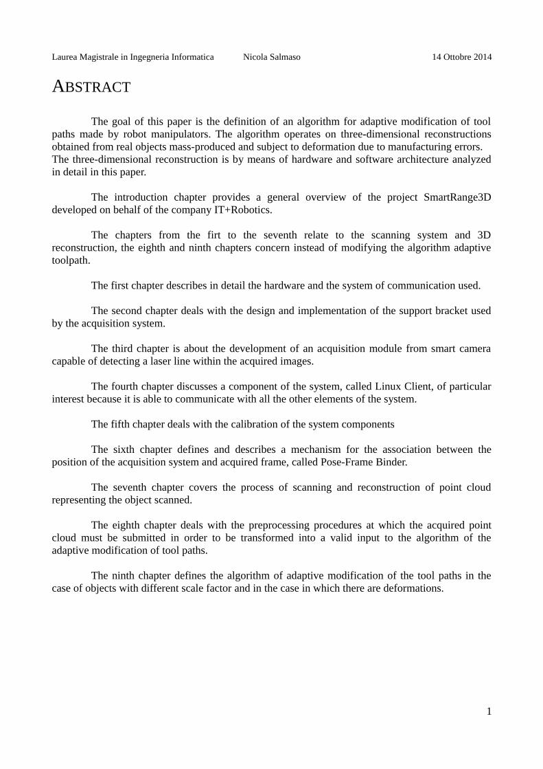
Fig. 2 – The communication system
1.2 THE ACQUISITION SYSTEM
The acquisition system has the server as its central element, although some operations aredriven directly by the client. The camera acquisition module, described in detail in Chapter 3, isinstalled inside the server. The server connects to the camera with a gigabit ethernet connection andthrough it :
• reads and writes the parameters of the smart camera as frame rate, ROI, exposure• sets the trigger of the camera (internal or external)• manages the switching between the different acquisition modes (normal or peak detection)• select the peak detection algorithm• reads and writes the parameters of the peak detection algorithm • acquires frame at setted framerate or on-demand
In this project, the trigger of the camera is external to it, and while this configuration ismade by the server, the trigger is supplied from an external circuit controlled directly by the clientthrough the parallel port. The same circuit also provides the on/off trigger of the laser pointers, onefor each laser.
5

Laurea Magistrale in Ingegneria Informatica Nicola Salmaso 14 Ottobre 2014
1.3 ENVIRONMENT, SOFTWARE AND USED LIBRARIES
Il server è stato realizzato su PC con sistema operativo Windows 7. Il softwareSmartRange3D realizzato all'interno del server è stato sviluppato inizialmente in ambienteMicrosoft Visual Studio 2008 e poi migrato nella sua versione finale in Visual Studio 2010. La partea più alto livello (GUI, gestione dei processi, protocollo ViDeE) è scritta in C# mentre la parte a piùbasso livello per la quale l'onere computazione e sono richieste performance il migliore possibile èscritta in C++. Per la triangolazione laser e la ricostruzione della point cloud sono state utilizzatelibrerie proprietarie di IT+Robotics, riadattate in alcune parti. Tali librerie a loro volta fannolargamente uso delle librerie open source
The server has been implemented on a PC with Windows 7 operating system. The softwareSmartRange3D developed within the server was initially developed under Microsoft Visual Studio2008 and then migrated in its final version in Visual Studio 2010. The part at the highest level (GUI,process management, protocol Videe messages) is written in C# while the lowest level for which thecomputation burden and required performance is the best it can be written in C ++. For the lasertriangulation and reconstruction of point cloud proprietary libraries of IT+Robotics have been used,adapted in some parts. These libraries in turn makes extensive use of open source libraries :
• OpenCV – Open Computer Vision • PCL – Point Cloud Library
The smart camera acquisition module has been written in C / C ++, has been integrated toSmartRange3D within Visual Studio 2010 and makes use of C libraries internal property ofTecnogamma, the manufacturer of the camera, which deal with the low level hardware managementof the device, as well as peak detection algorithms.
The client has been implemented on Linux operating system with RTAI (Real TimeApplication Interface) wich via a real time network card is able to communicate with the controllerof the robot in real time. The two modules developed within the client, ViDeEClient andComauIASLab, were written in C ++ in Eclipse development environment for C / C ++.
The robot manipulator used is the Comau C4G inside the laboratory IAS Lab at theUniversity of Padua.
For the design of the bracket SketchUp has been used. The TPS software has been developed on the operating system Ubuntu 13.04. was written in
C language ++ with Geany text editor and compiled using CMake 2.8.10.1. The software makes extensive use of open source library Point Cloud Library (PCL).
6

Laurea Magistrale in Ingegneria Informatica Nicola Salmaso 14 Ottobre 2014
2. MOUNTING BRACKET
2.1 THE BRACKET
The acquisition system formed by a smart camera and two laser pointer must be mounted ona rigid support which has:
• to mount to the wrist of the robot and rigidly coupled with it even in case of suddenmovements
• to allow adjusting the distance between the two blades laser • to allow adjusting the inclination of the two blades laser • to provide the possibility of changing the smart camera without removing all the bracket • to take account of cluttered cords and trigger chamber and laser • to provide a configuration in which the distance-blade blade is 500 mm
With these specifications was therefore designed and made a bracket composed of • metal section for the body• aluminum plates for the hardware of the devices and for the wrist of the robot• L-shape angular to join the plates to the body
Details regarding the design and implementation of the bracket are discussed in the followingparagraphs.
2.2 PLANNING AND DESIGN
The central body of the bracket is composed of a perforated metal section 600 mm long andwith square section 40x40mm, the technical characteristics are shown in Fig.3.
Fig. 3 – The section that makes up the body of the bracket
At the center of the body of the bracket an aluminum plate is fixed by means of threadedholes, screws and bolts. Similarly, another plate of the same size is fixed to wrist of the robot.Through plugs, threaded holes, screws and bolts, the two plate are fixed on one another allowingyou to mount the bracket to the wrist of the robot. The plugs have been inserted to make theattachment more stable and able to withstand sudden movements of the manipulator at its maximumspeed can move at 1.5 m / s.
At the ends of the section two supports with a cylindrical bore for the laser pointers aremounted, capable to adjust its tilt. Thanks to the structure of the perforated profiled the two laserprojectors can be moved and fixed in different positions, thus allowing to change the distancebetween them. Finally, at the center of the body of the bracket on the other side with respect to the
7
Laurea Magistrale in Ingegneria Informatica Nicola Salmaso 14 Ottobre 2014
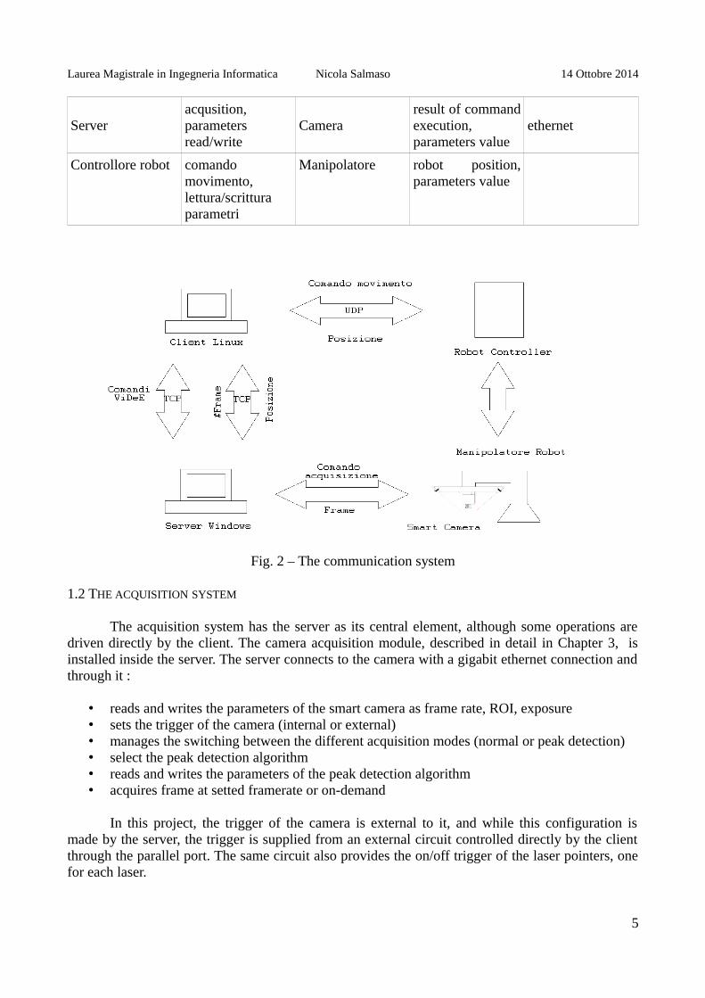
wrist of the robot, the camera supports are mounted using screws and two brackets L-shaped bolt.The two brackets allow you to attach two drilled plates to mount the smart camera. To change thesmart camera is sufficient to change these two plates and adjust the distance of the two corners,which are able to slide along the section. For the assembly of the smart camera only one angularand a single plate are neede but by using two pairs of them the stability can be improved while incase of impact the camera is protected on both sides. A schematic drawing of the angular is shownin Fig.4.
Fig.4 – L-shaped angular
They have been designed and manufactured plates for mounting three different cameras, twoof which have been used in the project:
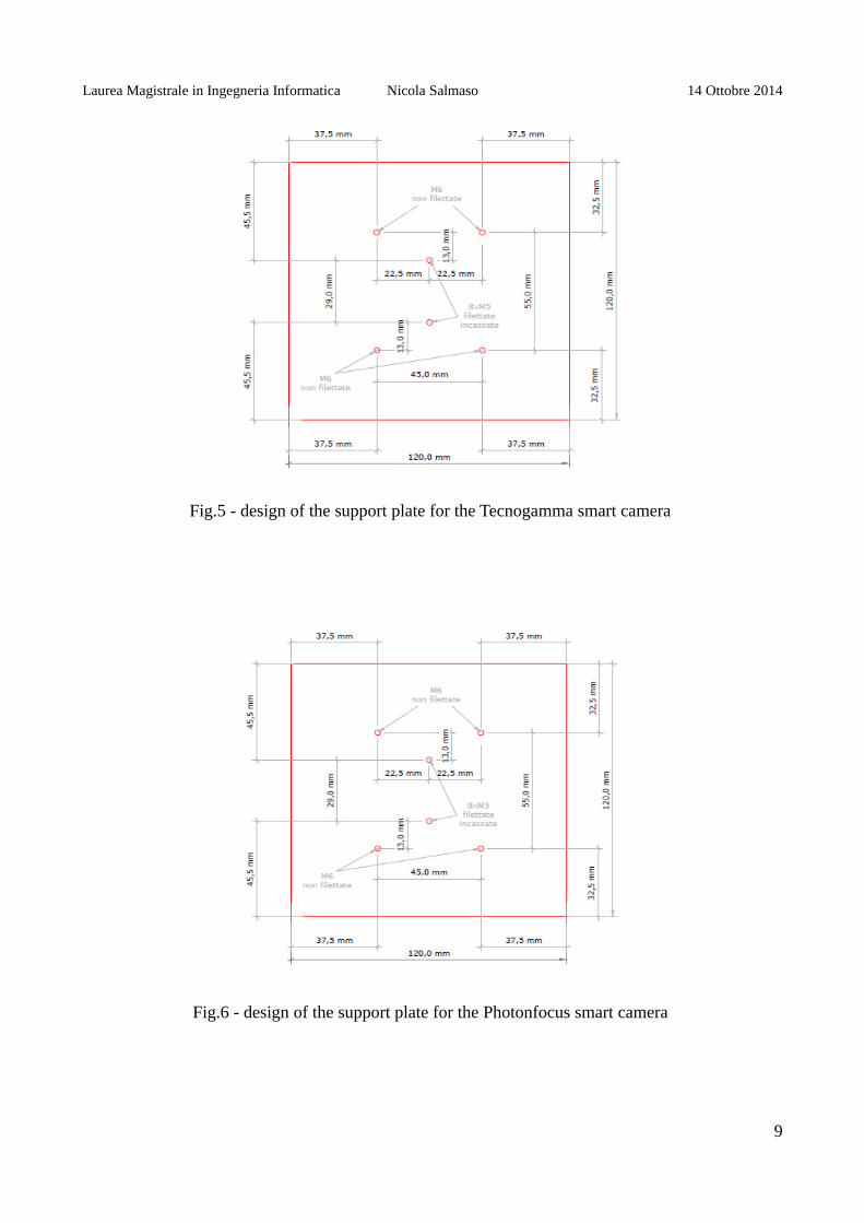
• Spectra GbE Camera – produced byTecnogamma – Fig.5• MV1-D2048x1088-3D03-760-G2-8 – produced by Photonfocus – Fig.6• MatrixVision – produced by Bluecougar (not used in the project) – Fig.7
The support system as a whole is schematically shown in Fig.8.
8
Laurea Magistrale in Ingegneria Informatica Nicola Salmaso 14 Ottobre 2014
Fig.5 - design of the support plate for the Tecnogamma smart camera
Fig.6 - design of the support plate for the Photonfocus smart camera
9

Laurea Magistrale in Ingegneria Informatica Nicola Salmaso 14 Ottobre 2014
Fig.7 - design of the support plate for the BlueCougar smart camera
Fig.8 – the bracket system
10

Laurea Magistrale in Ingegneria Informatica Nicola Salmaso 14 Ottobre 2014
2.3 REALIZATION
The plates were delivered together with the technical drawings of the workshop Physics atthe University of Padua where they were drilled and tapped.
The two plates for fixing the bracket to the wrist of the robot have been fixed one to thebody of the section and one to the wrist of the robot by means of screws on recessed holes closedwith bolts hex nut and between them by means of plugs and other screws fixed externally bolts withhexagon nut.
The brackets and mounts for the laser were fixed to aluminum profile with screws lockedinside the section with bolts hex nut. The lasers have been made to slide inside of the cylindricalsupports to be tight and securely fastened to the bracket.
The support plates of the smart camera were fixed to the corner pieces by means of screws.The smart camera was mounted to a plate on angular already fixed to the body of the bracket, theother pair angular-plate was then slid up to the edge of the camera for fixing the second plate. Oncethe second plate fixed to the bracket, the second angular movable anchor has been fixed.
Fig.9 – Smart camera and laser projectors mounted to the support bracket
11
Laurea Magistrale in Ingegneria Informatica Nicola Salmaso 14 Ottobre 2014
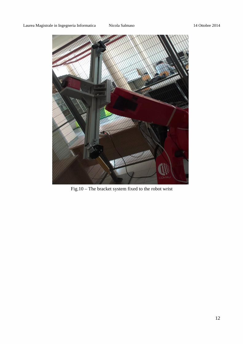
Fig.10 – The bracket system fixed to the robot wrist
12

Laurea Magistrale in Ingegneria Informatica Nicola Salmaso 14 Ottobre 2014
3. SMART CAMERA ACQUISITION MODULE
3.1 SMART CAMERA
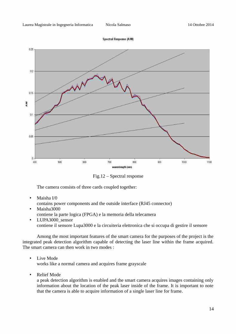
The smart camera for which I developed the form of acquisition is the Tecnogamma SpectraGbE. In Table 2 the technical characteristics of the camera are given. The graphs in Fig. 11 and 12show respectively the quantization energy and the spectral response.
Tab.2Caratteristica Descrizione
Sensor Cypress mod. LUPA 3000 Mono
Data transmission Gigabit ethernet
Trigger input Optoinsulated TTL or LVTTL
Strobe output TTL or LVTTL
Power supply 5-12 V
Maximum power input 10 W
Operating temperature 0-60 °C
Humidity 20-60 %
Fig.11 – quantum efficiency
13
Laurea Magistrale in Ingegneria Informatica Nicola Salmaso 14 Ottobre 2014
Fig.12 – Spectral response
The camera consists of three cards coupled together:
• Maisha I/0contains power components and the outside interface (RJ45 connector)
• Maisha3000contiene la parte logica (FPGA) e la memoria della telecamera
• LUPA3000_sensorcontiene il sensore Lupa3000 e la circuiteria elettronica che si occupa di gestire il sensore
Among the most important features of the smart camera for the purposes of the project is theintegrated peak detection algorithm capable of detecting the laser line within the frame acquired.The smart camera can then work in two modes :
• Live Modeworks like a normal camera and acquires frame grayscale
• Relief Modea peak detection algorithm is enabled and the smart camera acquires images containing onlyinformation about the location of the peak laser inside of the frame. It is important to notethat the camera is able to acquire information of a single laser line for frame.
14

Laurea Magistrale in Ingegneria Informatica Nicola Salmaso 14 Ottobre 2014
3.2 API
The acquisition package was written using the proprietary API of the producer of smartcamera in the C language.
HANDLE ConnectTCam (__in DWORD TCamIndex ,__out PWCHAR pName,__out PWCHAR pDesc)
The method allows you to connect to the smart camera, connected via gigabit ethernet, getting ahandle to the camera, the name and description of the device. The handle can then be used by othermethods to access the camera.
BOOL GetStrobeMode (__in HANDLE DeviceHandle, __out STROBE_MODE& sm); BOOL SetStrobeMode (__in HANDLE DeviceHandle,__in STROBE_MODE sm);
Respectively allow to read and set the four outputs that control the illuminators (not used within theproject) and four inputs which take an external trigger signal.
BOOL GetTrgMode(__in HANDLE DeviceHandle,__out TRG_MODE& trgm);BOOL SETTRGMODE(__IN HANDLE DEVICEHANDLE,__IN TRG_MODE TRGM);
Respectively allow to read and set the mode of triggering the acquisition, switching fromTRG_MODE :: FREERUN TRG_MODE :: ExTrigger regulated namely by acquisition or byinternal clock to acquire controlled by external trigger.
BOOL GetAcqMode(__in HANDLE DeviceHandle,__out ACQ_MODE& acqm); BOOL SetAcqMode(__in HANDLE DeviceHandle,__in ACQ_MODE acqm;
Allow to respectively read and write mode of acquisition. Allowed values are STOP, LIVE_ONLY,RELIEF_ONLY and RELIEF_LIVE. In STOP mode the camera is inhibited from acquiring;LIVE_ONLY mode the camera captures images in grayscale mode the camera captures imagesRELIEF_ONLY tablets containing information on the peak laser; Finally RELIEF_LIVE mode thecamera captures frames whose rows contain information about the frame either in grayscale and theposition of the peak laser, in relationship defined by the function SetHybridLiveRatio (not used forthe purpose of the project). All entries must be made with the camera parameters in ACQ_MODE :: STOP.
BOOL SetSharedMem ( __in HANDLE DeviceHandle,__in HANDLE hShMemEvent[2], __out PVOID ShMemAddr[2] );
The method defines events to manage the shared memory and the memory area used. It is calledonce in the initialization phase and is required in order to acquire in both modes (LIVE_ONLY andRELIEF_ONLY).
DWORD GetLive ( __in HANDLE DeviceHandle,__out TCamShMemory& ShMem, __out TCamFrameInfo& Info );BOOL ReleaseLive (__in HANDLE DeviceHandle, __in TCamShMemory ShMem);
GetLive is the method that allows to capture with the camera in live mode, going to copy a framefrom the read buffer to the memory area in the address :
((PUCHAR) ShMem.pMemArea) + Info.ImOffSet
15
Laurea Magistrale in Ingegneria Informatica Nicola Salmaso 14 Ottobre 2014
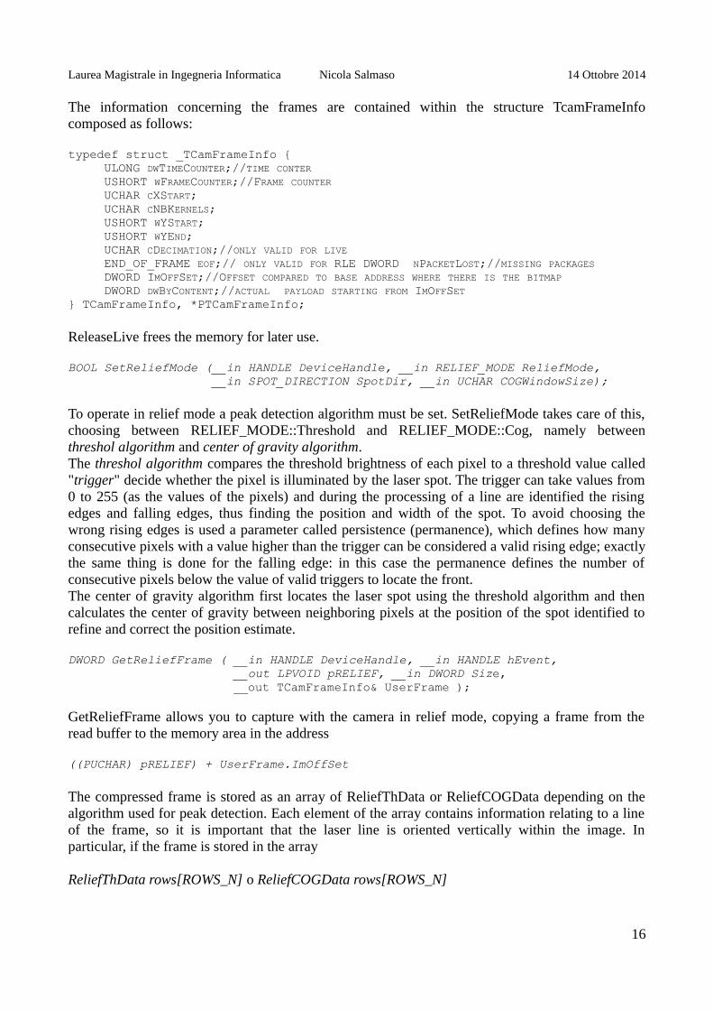
The information concerning the frames are contained within the structure TcamFrameInfocomposed as follows:
typedef struct _TCamFrameInfo { ULONG DWTIMECOUNTER;//TIME CONTER USHORT WFRAMECOUNTER;//FRAME COUNTER UCHAR CXSTART; UCHAR CNBKERNELS; USHORT WYSTART; USHORT WYEND; UCHAR CDECIMATION;//ONLY VALID FOR LIVE END_OF_FRAME EOF;// ONLY VALID FOR RLE DWORD NPACKETLOST;//MISSING PACKAGES DWORD IMOFFSET;//OFFSET COMPARED TO BASE ADDRESS WHERE THERE IS THE BITMAP DWORD DWBYCONTENT;//ACTUAL PAYLOAD STARTING FROM IMOFFSET } TCamFrameInfo, *PTCamFrameInfo;
ReleaseLive frees the memory for later use.
BOOL SetReliefMode (__in HANDLE DeviceHandle, __in RELIEF_MODE ReliefMode, __in SPOT_DIRECTION SpotDir, __in UCHAR COGWindowSize);
To operate in relief mode a peak detection algorithm must be set. SetReliefMode takes care of this,choosing between RELIEF_MODE::Threshold and RELIEF_MODE::Cog, namely betweenthreshol algorithm and center of gravity algorithm. The threshol algorithm compares the threshold brightness of each pixel to a threshold value called"trigger" decide whether the pixel is illuminated by the laser spot. The trigger can take values from0 to 255 (as the values of the pixels) and during the processing of a line are identified the risingedges and falling edges, thus finding the position and width of the spot. To avoid choosing thewrong rising edges is used a parameter called persistence (permanence), which defines how manyconsecutive pixels with a value higher than the trigger can be considered a valid rising edge; exactlythe same thing is done for the falling edge: in this case the permanence defines the number ofconsecutive pixels below the value of valid triggers to locate the front. The center of gravity algorithm first locates the laser spot using the threshold algorithm and thencalculates the center of gravity between neighboring pixels at the position of the spot identified torefine and correct the position estimate.
DWORD GetReliefFrame ( __in HANDLE DeviceHandle, __in HANDLE hEvent, __out LPVOID pRELIEF, __in DWORD Size, __out TCamFrameInfo& UserFrame );
GetReliefFrame allows you to capture with the camera in relief mode, copying a frame from theread buffer to the memory area in the address
((PUCHAR) pRELIEF) + UserFrame.ImOffSet
The compressed frame is stored as an array of ReliefThData or ReliefCOGData depending on thealgorithm used for peak detection. Each element of the array contains information relating to a lineof the frame, so it is important that the laser line is oriented vertically within the image. Inparticular, if the frame is stored in the array
ReliefThData rows[ROWS_N] o ReliefCOGData rows[ROWS_N]
16

Laurea Magistrale in Ingegneria Informatica Nicola Salmaso 14 Ottobre 2014
with ROWS_N equal to the number of rows of the frame acquired, it will follow that rows[i] willhold the position and the width in pixels of the laser line in i-th row of the image.
3.3 CAMERADEVICE INTERFACE
The libraries developed by IT + Robotics allow you to use a capture device in severalprocedures. To integrate these libraries the acquisition module must then implement the interfaceCameraDevice, written in C language ++.
CameraDevice::CameraDeviceTecnoGamma()
Class constructor, here are defined default parameters that define the mode of acquisition, the peakdetection algorithm and the capture trigger.
void CameraDevice::openInternal()
Method to open the connection to the device. Call the API ConnectTCam and gets a handle to thedevice.
void CameraDevice::stopInternal()
Stops capturing. Call the API passing as a parameter SetAcqMode ACQ_MODE :: Stop.
void CameraDevice::startInternal()
Initializes the acquisition in live mode or relief depending on the setting, by setting the trigger modedesired. With relief mode setting switches to stop mode in order to modify the parameters; calls theAPI to read the GetStrobeMode STROBE_MODE structure that contains information about inputand strobe trigger used; modifies the structure accessed to set one of four trigger as a trigger input,calls the API SetStrobeMode passing the modified structure, and finally calls the API SetTrgModeto switch from stop mode ExTrigger mode or to start capturing driven by external trigger.
const vector<string> CameraDevice::getAvailableCameraID()
Returns a string array containing the IDs of available devices. Call the API EnumerateTCams.
void CameraDevice::acquireInternal(CVImage& image)
The method to acquire a frame from the buffer memory of the device. The aquired frame in reliefmode is stored in an array, the array is then processed and an object is created CVImage (CV :: Matobject library OpenCV) to two channels containing respectively the position and width of the laserspot within the row. They are also appended to the object as dummy rows and timestampinformation framecounter
17

Laurea Magistrale in Ingegneria Informatica Nicola Salmaso 14 Ottobre 2014
Fig.13 – implementation of the method acquireInternal interface CameraDevice
3.4 CAMERADEVICEPEAKDETECTOR INTERFACE
To operate the triangulation and 3D reconstruction the libraries of IT+Robitcs use objectsthat implements the CameraDevicePeakDetector interface. To integrate to these libraries theacquisition module implements this interface. Extending the interface already CameraDevice, theonly method left to implement is
void CameraDevicePeakDetector::decodePeaksStatic(const CVImage& sourceimage, vector<Cloud<PointImagePeak>::Ptr >& peaks,vector<CVImage::Ptr>& images2d)
Starting from an image containing information about the position of the laser line the methodreconstructs the 3D point cloud of the surface on which the laser line lies. The image previouslyprocessed in the method of acquireInternal CameraDevice is processed further and stored in astructure adapted to contain a point cloud. This method will be invoked from an internal classlibrary of IT+Robotics who will perform the triangulation of the 3D point cloud from the back.
18
Laurea Magistrale in Ingegneria Informatica Nicola Salmaso 14 Ottobre 2014
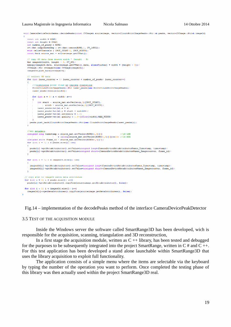
Fig.14 – implementation of the decodePeaks method of the interface CameraDevicePeakDetector
3.5 TEST OF THE ACQUISITION MODULE
Inside the Windows server the software called SmartRange3D has been developed, wich isresponsible for the acquisition, scanning, triangulation and 3D reconstruction,
In a first stage the acquisition module, written as C ++ library, has been tested and debuggedfor the purposes to be subsequently integrated into the project SmartRange, written in C # and C ++.For this test application has been developed a stand alone launchable within SmartRange3D thatuses the library acquisition to exploit full functionality.
The application consists of a simple menu where the items are selectable via the keyboardby typing the number of the operation you want to perform. Once completed the testing phase ofthis library was then actually used within the project SmartRange3D real.
19

Laurea Magistrale in Ingegneria Informatica Nicola Salmaso 14 Ottobre 2014
Fig.15 – The stand alone testing application for the acquisition module
20

Laurea Magistrale in Ingegneria Informatica Nicola Salmaso 14 Ottobre 2014
4. LINUX CLIENT
4.1 C4G PROTOCOL
One of the key features of the linux client is the ability to communicate with the robotcontroller to drive the movement of the manipulator. To do this in the client a C++ module isinstalled, able to send via UDP packets in JSON format containing the commands interpreted by aserver listening in the controller.
In Table 3 are listed the names of the commands and their effect.
Tab.3 – C4G comandsNome comando Effetto
ComauProtocol(string IP, int PORT) Class constructor. Opens a UDP connection
MOVE(CartPosition pos, int camera_fps) Moves the robot and sets the frame rate of thecamera. Receives in real time the position of therobot.
SET_OVERRIDE (int override) Sets the speed of the manipulator to a percentageof the speed that is set
SET_LINSPEED (double linspeed) Sets the speed of linear motion of themanipulator
getStaticPose() Receives the current position of the manipulator
prepareCartPacket(Jzon::Array pos, intcamera_fps)
Constructs a package in json format to send tothe robot controller
sendPacket() Send a message previously built withprepareCartPacket json to the robot controller
recvPacket() Receives a message from the json controller
4.2 VIDEE PROTOCOL
The Windows server contains the acquisition module and the procedures for triangulationand scan but it is the client that gives the commands to start these procedures. To do that itcommunicates via TCP / IP with the server, exchanging messages of Videe protocol developed byIT+Robotics.
In Table 4 are listed the names of the commands and their effect.
21

Laurea Magistrale in Ingegneria Informatica Nicola Salmaso 14 Ottobre 2014
Tab.4Nome comando Effetto
INIT_CYCLE Initialize the data structures to be used
INIT_CALIBRATION Initialize the calibration procedure
PERFORM_CALIBRATION Perform calibrations enabled
GRAB_IMAGE Acquire a frame from smart camera
SET_POSTION Receive the start and end positions of scan
START_SCAN Start the scanning process
STOP_SCAN Terminate the scanning procedure
RESET Clear the data structures used by the various processes
22
Laurea Magistrale in Ingegneria Informatica Nicola Salmaso 14 Ottobre 2014
5. CALIBRATION
5.1 CAMERA CALIBRATION
Before passing to the acquisition, triangulation and reconstruction is necessary to calibrateall elements of the system. Regarding the camera has been used a procedure libraries ofIT+Robotics that requires several frames acquired from the device in which there is a black andwhite checkerboard with number of squares and their sizes known.
In order to facilitate the task of acquiring frames from different locations has been exploitedthe fact that the camera has been already fixed to the bracket attached to the wrist of the robot andusing the teach pendant it is possible to read the 3D positions of the robots and save them to a textfile. Using the text file was then possible to move the manipulator in succession in the positionspreviously read through the protocol C4G and capture frames by messages of ViDeE protocol. Thealgorithm is very simple and is as follows:
1. Read the next location from the text file 2. Send the position to the robot controller in a C4G message via UDP 3. Wait until the robot is positioned 4. Capture a frame by sending to SmartRange3D a GRAB_IMAGE command of Videe
protocol 5. Ends when there are no more positions to be read
With this procedure, within SmartRange3D, the Windows server, frames are collected in anumber equal to the positions that the manipulator has taken. At the end of it the calibration of thecamera can be started directly from the graphical interface of SmartRange3D or via a Videe sentby the ViDeEClient module of the Linux client.
The benefits of having saved positions on a text file and the ability to perform acquisitionsautomatically are
• repeatability of the operation • possibility of replacing the board • possibility of removing or adding new positions • reusability of positions for other types of calibration • reusability of the positions for the calibration of other rooms
When calibrating smart camera 70 frames were used taken at different angles and heights,with a 15x25 chessboard with squares of 20mm. The resulting reprojection error calculated is equalto 0.1586
5.2 LASER CALIBRATION
The two laser pointers need to be calibrated. To do this, a procedure library IT + Roboticshas been used that similarly to the case of camera calibration requires frames captured at differentpositions in which the laser lines are visible.
For the acquisition of the frame, the algorithm used for the camera has been reused bychanging the type of acquisition by normal mode to laser mode. The positions of acquisition are thesame and it was thus possible to reuse the entire procedure of the calibration cycle of the camera.
23
Laurea Magistrale in Ingegneria Informatica Nicola Salmaso 14 Ottobre 2014
The reprojection error calculated is equal to 0.2787 and 0.4413 for a laser for the other.
5.3 TOOL CALIBRATION
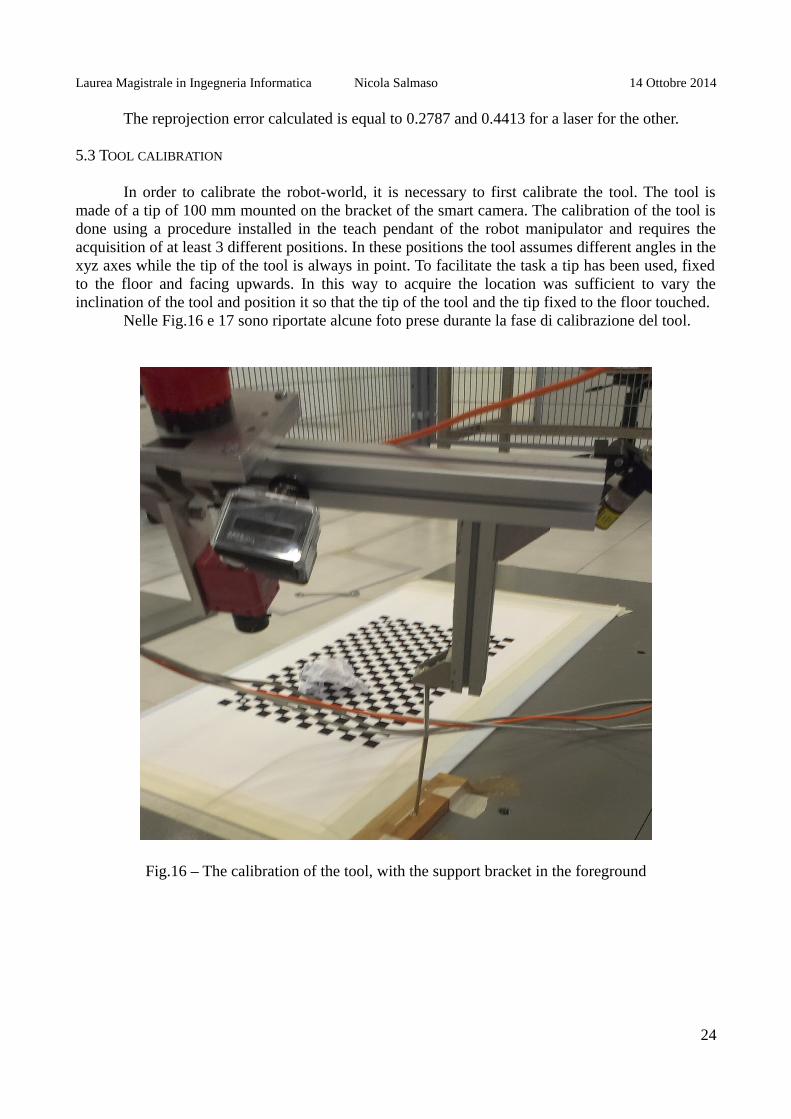
In order to calibrate the robot-world, it is necessary to first calibrate the tool. The tool ismade of a tip of 100 mm mounted on the bracket of the smart camera. The calibration of the tool isdone using a procedure installed in the teach pendant of the robot manipulator and requires theacquisition of at least 3 different positions. In these positions the tool assumes different angles in thexyz axes while the tip of the tool is always in point. To facilitate the task a tip has been used, fixedto the floor and facing upwards. In this way to acquire the location was sufficient to vary theinclination of the tool and position it so that the tip of the tool and the tip fixed to the floor touched.
Nelle Fig.16 e 17 sono riportate alcune foto prese durante la fase di calibrazione del tool.
Fig.16 – The calibration of the tool, with the support bracket in the foreground
24

Laurea Magistrale in Ingegneria Informatica Nicola Salmaso 14 Ottobre 2014
Fig.17 – The calibration of the tool, with the teach pendant in the foreground
5.4 WORLD-ROBOT CALIBRATION
Once the calibration of the tool has been performed, the robot comau is able to know theposition of the tool in every configuration of the joints. The calibration of the robot world can thenbe performed, locating the XY plane using the calibrated tool. To do so the board previously usedfor calibration of the camera has been reused, but also a different checkerboard can be usedprovided that it is positioned in the XY plane.
The calibration procedure is performed via the teach pendant of the robot controller. Duringthe procedure is required to place the tool in three different positions:
• O : origin of the plane • X: any point on the X axis • XY: any point on the line parallel to the Y axis passing through the point chosen previously
Once these three points were chosen, the procedure inside the robot controller reconstructs the XY
25

Laurea Magistrale in Ingegneria Informatica Nicola Salmaso 14 Ottobre 2014
plane, Once these three points were chosen, the procedure inside the robot controller reconstructsthe XY plane, from which extrapolates the 3D reference system composed of three axes xyze origin.The reference system thus calculated is stored in the controller and selecting it it is possible to movethe robot coordinates expressed in this reference system.
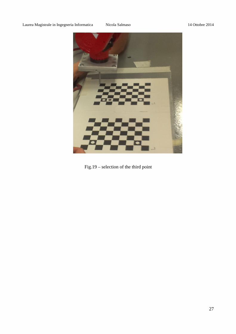
To facilitate the operation of choosing these three points, they were taken in threeintersections each formed of four blocks of the chessboard. In Fig.17, 18 and 19 are shown thephotos taken at the time of selection of the three points. The photos relate to the first calibrationwhich has been used in a different board than the final one.
Fig.17 – origin selection
Fig.18 – selection of the point along the x axis
26
Laurea Magistrale in Ingegneria Informatica Nicola Salmaso 14 Ottobre 2014
Fig.19 – selection of the third point
27

Laurea Magistrale in Ingegneria Informatica Nicola Salmaso 14 Ottobre 2014
6. COUPLING POSE AND FRAME
6.1 CONSTANT SPEED INTERPOLATOR
The scanning procedure necessary to reconstruct a 3D point cloud requires a mechanismable to associate to each frame acquired the camera position in the spatial coordinates with respectto the chosen reference system. This mechanism is made possible by a set of hardware and softwarethat is called Pose-Frame binder and will be analyzed in detail in the next paragraph.
Inside the IT+Robotics libraries an interpolator called TrackerConstantSpeed isimplemented providing a linear scanning motion with a constant speed. This type of scan is used forsystems mounted on the conveyor belt in which the acquisition system remains stationary and theobject to be scanned flowing beneath it.
For a first testing stage this interpolator has been used, adapting it to the case ofSmartRange3D. In particular in SmartRange3D is not the object which moves but the systemacquisition and therefore it was necessary to reverse the direction of motion within the settingsinterpolator.
The constant speed interpolator does not need to receive in real time the positions of therobot, it is sufficient to provide the initial position, the final position and the speed of movementand the interpolator is responsible to interpolate the positions assuming a constant frame rate.
The algorithm that makes use of the constant speed interpolator a has been implementedwithin the Linux client, which is responsible to control the robot by using the protocol C4Gmanipulate and operate the procedures SmartRange3D through commands Videe. Specifically, thealgorithm operates as follows :
1. Read the initial position and the final file 2. Send the C4G command Move(starting position) via UDP to the controller to position the
manipulator in the initial position 3. Sets the speed constant, linear motion and linear interpolation through messages of the C4G
protocol4. Send the Videe command SetScanPosition(initial position, final position) via a TCP to
SmartRange3D to initialize the binder 5. Send the command to Videe StartScan SmartRange to start the scan and at the same time
sends the C4G command Move(end position) to set in motion the manipulator 6. When the robot has arrived at its final position, the scan stops sending the Videe command
StopScan
At the end of the procedure, when SmartRange3D receives the StopScan command, theprocess of triangulation and reconstruction of 3D point cloud starts. Specifically, the procedurereconstructs a partial point cloud for each frame, by making the position of the laser line and thenmerge with the clouds of partial points in the final one.
6.2 POSE-FRAME BINDER
Scanning by interpolator is designed for fixed acquisition systems, mounted on to aconveyor belt which slide the objects to be scanned and is then a choice for limiting the physicalarchitecture available. With the possibility of moving the manipulator and obtain its position in realtime constraints of linear motion and a constant speed can be eliminated, at the cost of greatercomplexity of the reconstruction algorithm.
28
Laurea Magistrale in Ingegneria Informatica Nicola Salmaso 14 Ottobre 2014
To function, this procedure needs a component able to associate to each frame acquired theposition of the acquisition system in the reference system adopted.
The best candidate is the Linux client that is responsible for controlling the movement bymeans of the protocol C4G and the acquisition by Videe and is therefore in possession, at each stepof the scan algorithm, of the frame number of the frame in acquisition and the current position ofthe manipulator. However, there is no a one to one correspondence between the number of framesand the positions, the number of frames depends on the frame rate chosen while the positions of themanipulator arrive to the client via UDP and are subject to packet loss and generally do not have arate constant. In addition to the acquisition of the frame while being a constant frame rate is subjectto error and some frames may be corrupted and then unwrapped. There may then be three cases :
1. one to one correspondence between the frame number and positions (ideal case) 2. one or more frame number different for each distinct location 3. one or more positions for each frame number distinct
In memory an array of pairs (# frame, 3D position) is kept .The first case is the most simple and merely insert into the array a pair (# Frame, 3D
position) each time a new pair is available.Assumed without loss of generality, in the second case at each position of the manipulator
correspond various distinct, sequential frame numbers. Given two frames frame i and framei wehave:
#(framei) > #(framei) ⇔ framei was acquired after framej
If k frame numbers framei,1, framei,2, … , framei,k are associated to the position Pi then these k framenumbers correspond to the manipulator frame captured when he was in a position between Pi andPi+1.The choice of the frame that involves the least error is the frame with the smallest frame numberamong those associated with Pi, namely framei,1, as is the temporally nearest to the instant in whichthe robot is located in position Pi. In the array is then inserted the pair (#(framei,1) , Pi).
The third case provides multiple positions associated with the same frame number. Theprotocol messages C4G traveling via UDP and could get the client out of order. In our case,however, the client-controller connection is direct and messages traveling over a single cable thuspreventing the possibility of their arriving out of order. So without loss of generality we can assumethat the robot positions arriving at the client linux arrive in chronological order. If k positions P i,1,Pi,2, … , Pi,k are associated to the frame framei these correspond to the positions taken by the robot inthe time passed between the acquisition of framei and the acquisition of framei+1. Following thesame logic as the previous case, the minor error is given by choosing the first between the positionsassociated with framei, namely Pi,1, since it is the position temporally closer to the time ofacquisition offramei. In the array is then inserted the pair (#(framei) , Pi,1).
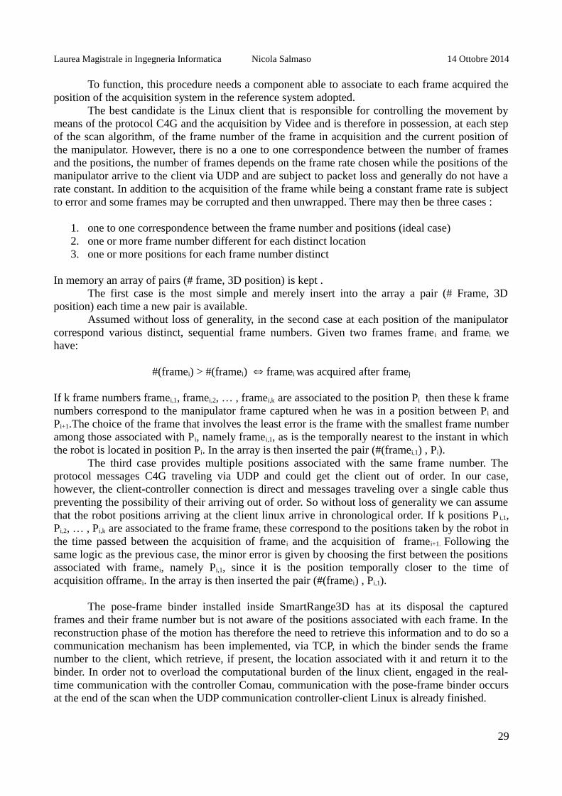
The pose-frame binder installed inside SmartRange3D has at its disposal the capturedframes and their frame number but is not aware of the positions associated with each frame. In thereconstruction phase of the motion has therefore the need to retrieve this information and to do so acommunication mechanism has been implemented, via TCP, in which the binder sends the framenumber to the client, which retrieve, if present, the location associated with it and return it to thebinder. In order not to overload the computational burden of the linux client, engaged in the real-time communication with the controller Comau, communication with the pose-frame binder occursat the end of the scan when the UDP communication controller-client Linux is already finished.
29
Laurea Magistrale in Ingegneria Informatica Nicola Salmaso 14 Ottobre 2014
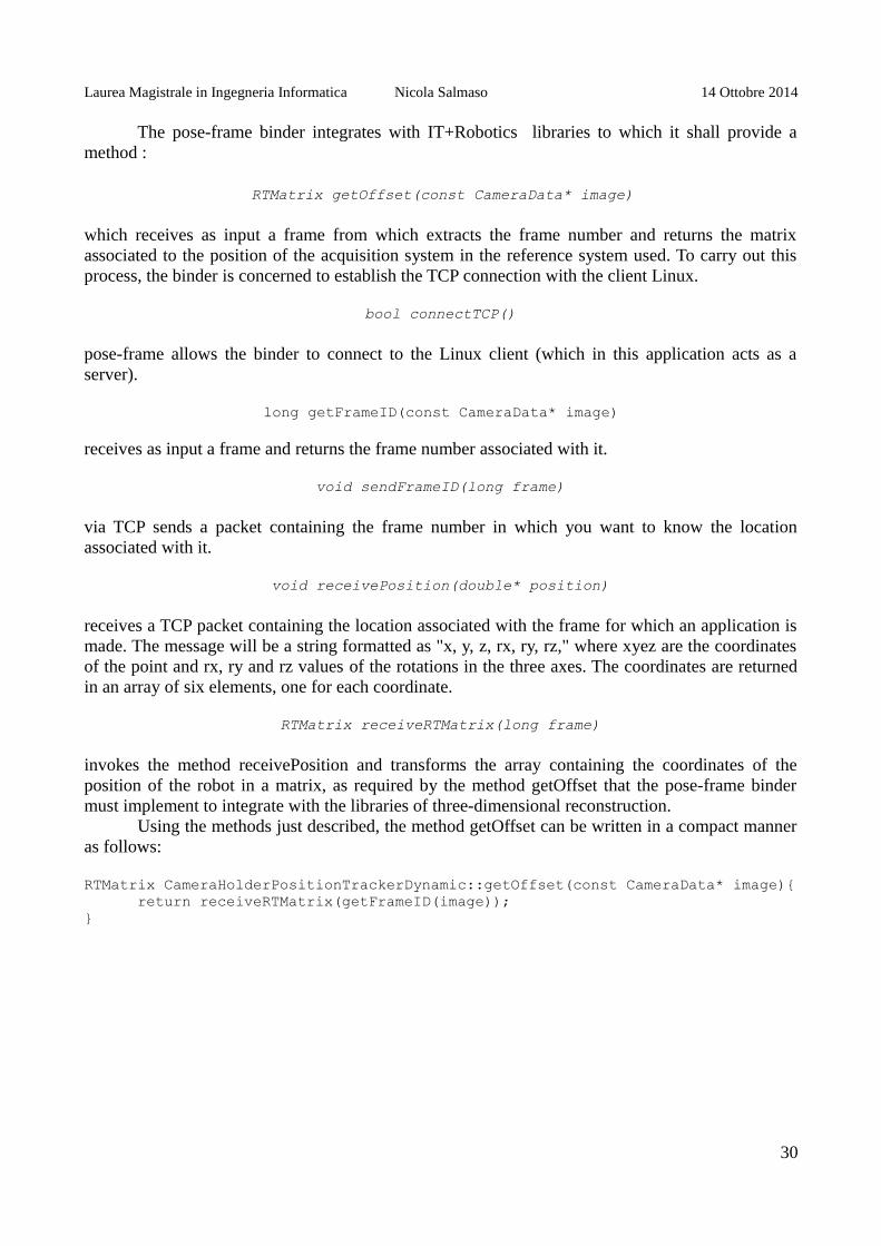
The pose-frame binder integrates with IT+Robotics libraries to which it shall provide amethod :
RTMatrix getOffset(const CameraData* image)
which receives as input a frame from which extracts the frame number and returns the matrixassociated to the position of the acquisition system in the reference system used. To carry out thisprocess, the binder is concerned to establish the TCP connection with the client Linux.
bool connectTCP()
pose-frame allows the binder to connect to the Linux client (which in this application acts as aserver).
long getFrameID(const CameraData* image)
receives as input a frame and returns the frame number associated with it.
void sendFrameID(long frame)
via TCP sends a packet containing the frame number in which you want to know the locationassociated with it.
void receivePosition(double* position)
receives a TCP packet containing the location associated with the frame for which an application ismade. The message will be a string formatted as "x, y, z, rx, ry, rz," where xyez are the coordinatesof the point and rx, ry and rz values of the rotations in the three axes. The coordinates are returnedin an array of six elements, one for each coordinate.
RTMatrix receiveRTMatrix(long frame)
invokes the method receivePosition and transforms the array containing the coordinates of theposition of the robot in a matrix, as required by the method getOffset that the pose-frame bindermust implement to integrate with the libraries of three-dimensional reconstruction.
Using the methods just described, the method getOffset can be written in a compact manneras follows:
RTMatrix CameraHolderPositionTrackerDynamic::getOffset(const CameraData* image){return receiveRTMatrix(getFrameID(image));
}
30
Laurea Magistrale in Ingegneria Informatica Nicola Salmaso 14 Ottobre 2014
7. POINT CLOUD ACQUISITION
7.1 POINTCLOUDGRABBER AND TRIANGULATION
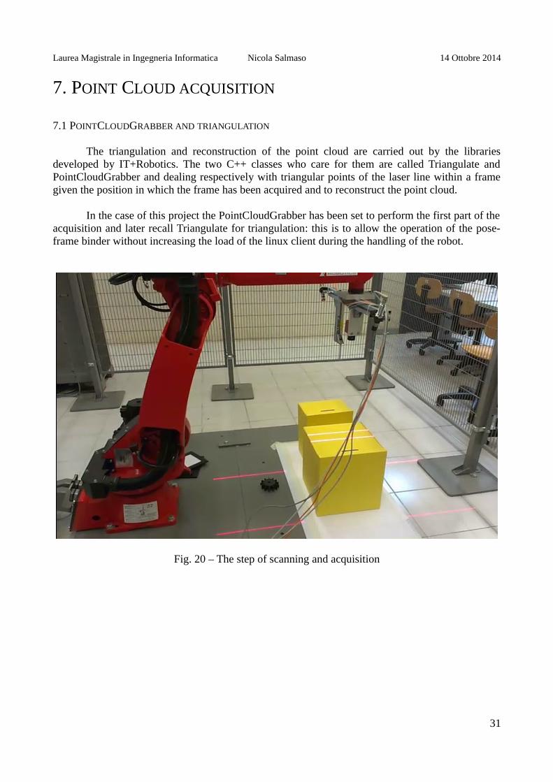
The triangulation and reconstruction of the point cloud are carried out by the librariesdeveloped by IT+Robotics. The two C++ classes who care for them are called Triangulate andPointCloudGrabber and dealing respectively with triangular points of the laser line within a framegiven the position in which the frame has been acquired and to reconstruct the point cloud.
In the case of this project the PointCloudGrabber has been set to perform the first part of theacquisition and later recall Triangulate for triangulation: this is to allow the operation of the pose-frame binder without increasing the load of the linux client during the handling of the robot.
Fig. 20 – The step of scanning and acquisition
31
Laurea Magistrale in Ingegneria Informatica Nicola Salmaso 14 Ottobre 2014
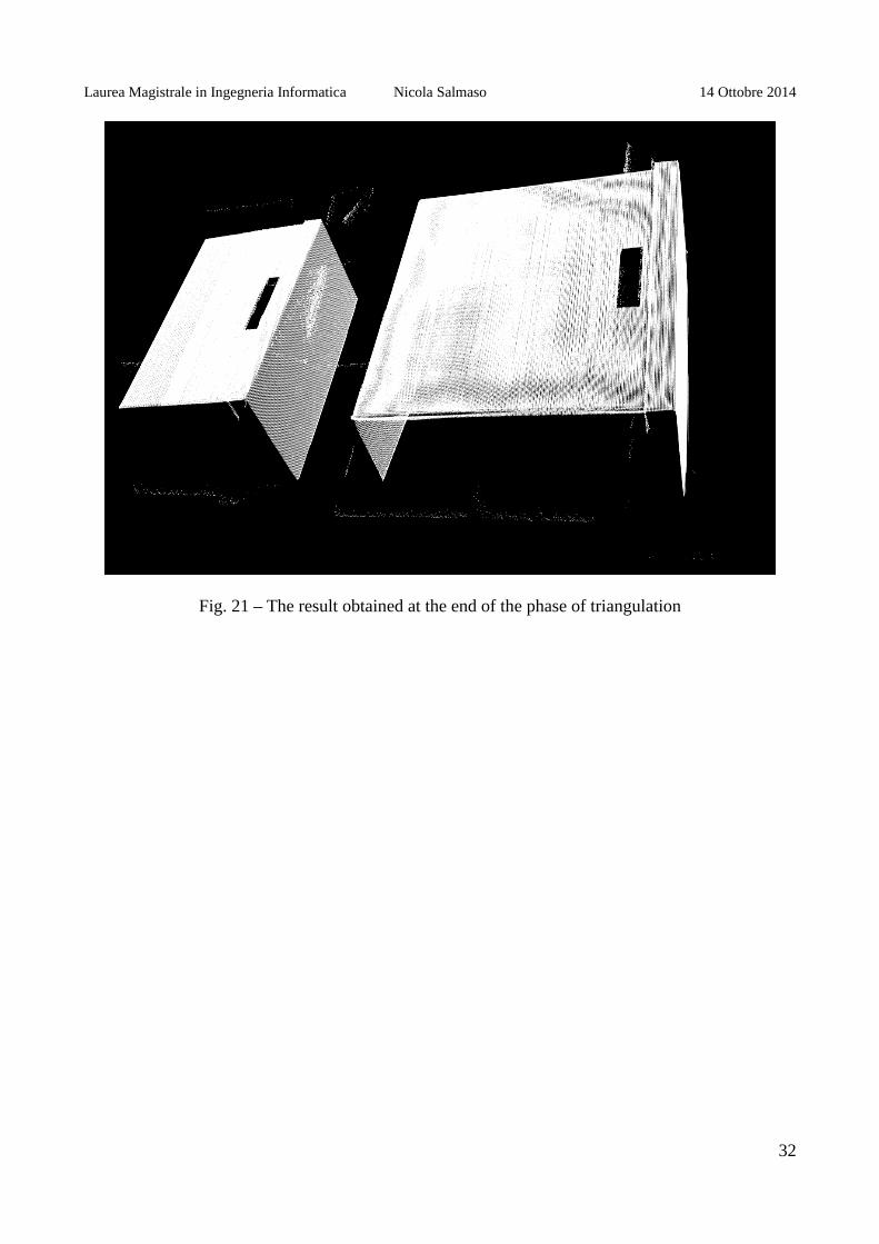
Fig. 21 – The result obtained at the end of the phase of triangulation
32
Laurea Magistrale in Ingegneria Informatica Nicola Salmaso 14 Ottobre 2014
8. PREPROCESSING
8.1 PURPOSE
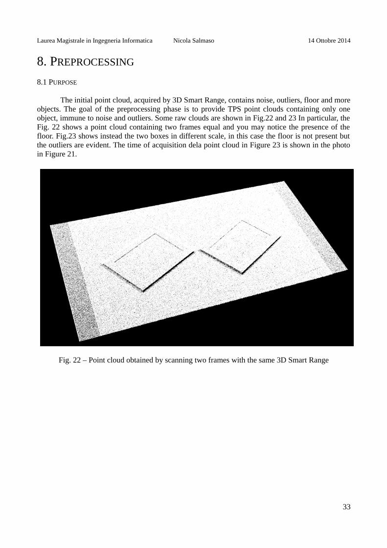
The initial point cloud, acquired by 3D Smart Range, contains noise, outliers, floor and moreobjects. The goal of the preprocessing phase is to provide TPS point clouds containing only oneobject, immune to noise and outliers. Some raw clouds are shown in Fig.22 and 23 In particular, theFig. 22 shows a point cloud containing two frames equal and you may notice the presence of thefloor. Fig.23 shows instead the two boxes in different scale, in this case the floor is not present butthe outliers are evident. The time of acquisition dela point cloud in Figure 23 is shown in the photoin Figure 21.
Fig. 22 – Point cloud obtained by scanning two frames with the same 3D Smart Range
33

Laurea Magistrale in Ingegneria Informatica Nicola Salmaso 14 Ottobre 2014
Fig 23 – Point cloud obtained by scanning two boxes at different scales with Smart 3D Range
8.2 FLOOR REMOVAL
For the removal of the floor a dual approach was used. Before an automatic procedure dealswith finding the floor inside the point cloud segmentation algorithm using the plan. If the algorithmdoes not completely remove the floor, or would remove wrong side of the object to be insulated, thesoftware provides an alternative manual procedure.
During the procedure manual, the minimum and maximum values that can take the z-coordinate of the points of the cloud are given. In the reference system used for the reconstructionof point cloud the floor plane coincides with the XY plane and all points in the plane have the samez. The manual procedure is therefore extremely effective going to completely remove the floor,leaving intact the object to be insulated.
The point cloud shown in Figure 22 at the end of the procedure for removal of the floor isvisible in Fig.24. The outliers that were not visible due to the floor are now evident.
34
Laurea Magistrale in Ingegneria Informatica Nicola Salmaso 14 Ottobre 2014
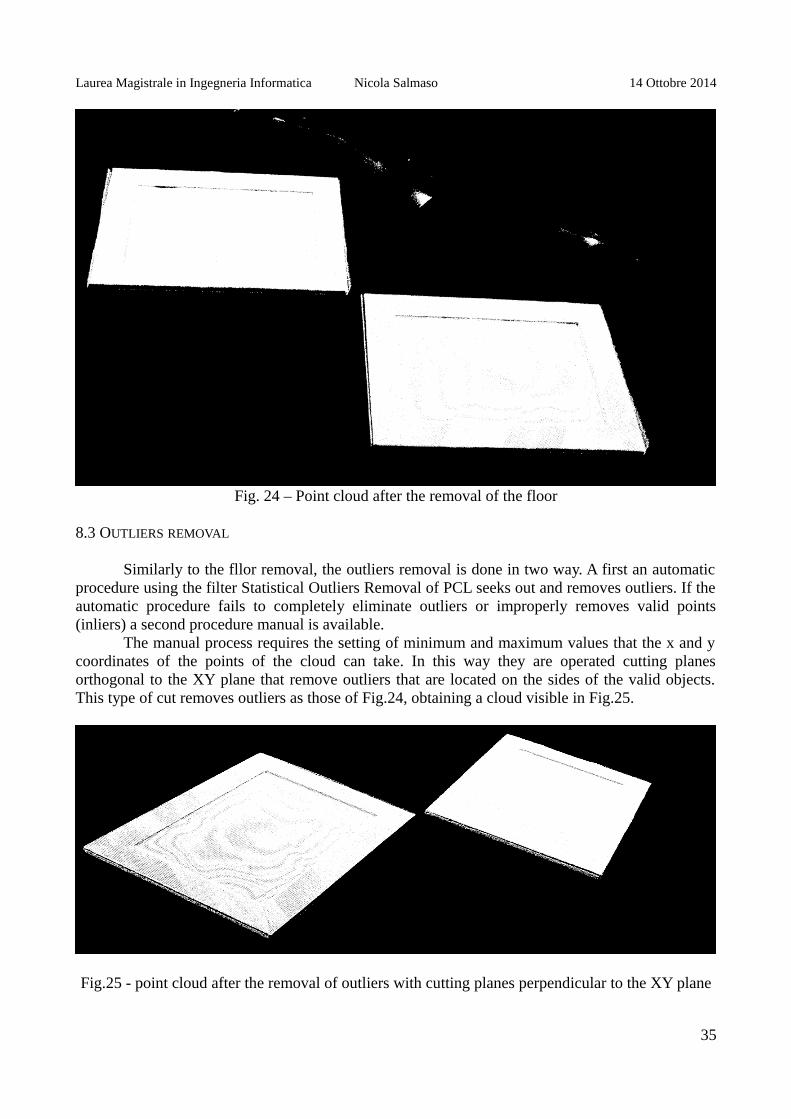
Fig. 24 – Point cloud after the removal of the floor
8.3 OUTLIERS REMOVAL
Similarly to the fllor removal, the outliers removal is done in two way. A first an automaticprocedure using the filter Statistical Outliers Removal of PCL seeks out and removes outliers. If theautomatic procedure fails to completely eliminate outliers or improperly removes valid points(inliers) a second procedure manual is available.
The manual process requires the setting of minimum and maximum values that the x and ycoordinates of the points of the cloud can take. In this way they are operated cutting planesorthogonal to the XY plane that remove outliers that are located on the sides of the valid objects.This type of cut removes outliers as those of Fig.24, obtaining a cloud visible in Fig.25.
Fig.25 - point cloud after the removal of outliers with cutting planes perpendicular to the XY plane
35

Laurea Magistrale in Ingegneria Informatica Nicola Salmaso 14 Ottobre 2014
In case of outliers positioned above the object to be insulated, the same procedure used forthe manual removal of the floor is used, where through two minimum and maximum values of z aredefined two planes parallel to the XY plane. Only points between these two levels will beconsidered valid while the other will be considered outliers and removed. This is the case of thepoint cloud in Figure 3, that after the operation for removal of outliers becomes the cloud visible inFig.6.
Fig.26 - point cloud after the removal of outliers with cutting planes parallel to the XY plane
8.4 OBJECT INSULATION
The isolation of the object is made necessary by the presence of multiple objects within thescan. In the real case the point cloud, to the specifications of the project 3D Smart Range, containonly one object. At the time of scanning it was nevertheless chose to insert for convenience moreobjects within a same point cloud in order to have a scan for each pair of objects on which toperform the tool path streatching.
The procedure to manually insulate the object uses the same approach used for the removalof outliers which sets the minimum and maximum values considered valid for the x and ycoordinates, defining cutting planes orthogonal to the XY plane. The objects within the scan arearranged side by side along the same reference axis (x or y), and this approach allows partitioningthe cloud into two cloud containing exactly one object each.
36
Laurea Magistrale in Ingegneria Informatica Nicola Salmaso 14 Ottobre 2014
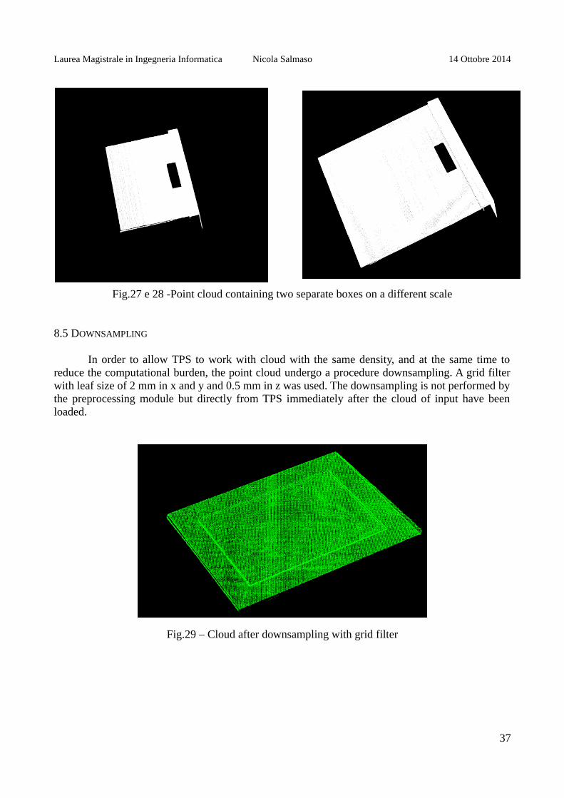
Fig.27 e 28 -Point cloud containing two separate boxes on a different scale
8.5 DOWNSAMPLING
In order to allow TPS to work with cloud with the same density, and at the same time toreduce the computational burden, the point cloud undergo a procedure downsampling. A grid filterwith leaf size of 2 mm in x and y and 0.5 mm in z was used. The downsampling is not performed bythe preprocessing module but directly from TPS immediately after the cloud of input have beenloaded.
Fig.29 – Cloud after downsampling with grid filter
37

Laurea Magistrale in Ingegneria Informatica Nicola Salmaso 14 Ottobre 2014
9. TOOL PATH STRETCHING
9.1 TOOL PATH
The tool path (TP) is the path that a tool mounted on a manipulator robot performs during amachining cycle. Without loss of generality the TP can be defined as a broken line in 3D space andbecause the tool moves on the surface of the object also the TP lying on it. Given a point cloudcontaining the reference object, which will be compared to the real object, the TP can be derivedfrom the same by taking a subset of the points of its surface and possibly interpolandoli to a higherdensity.
In Fig.30 a tool path defined on the point cloud of a frame is shown.
Fig.30 – Tool Path defined on a frame
9.2 TPS WITH AFFINE TRANSFORMATION
Given
• the point cloud of a reference object O • the point cloud of an object S equal to O except for a scale factor and a rototranslation
transformation• a TP defined on O
we want to fit TP so that it follows the surface S, consistent with how it was defined on O.Therefore we want to find a transformation steps from TP to TP ', where TP' is a tool path on S.
Let T be the affine transformation that allows you to switch from O to S, ie, T (O) = S. Then T cantransform any point of O to the corresponding point of S. Since TP is defined on O, we have:
38
Laurea Magistrale in Ingegneria Informatica Nicola Salmaso 14 Ottobre 2014
∀ p belongs to TP => p belongs to O
Intuitively we have that T (TP) = TP 'and it is therefore sufficient to find the transformation thatsends O in S and apply it to the TP.
The algorithm assumes to work with a pair of the same object to two different scale factorsand with a possible rotation-translation, it is then to find the affine transformation which transformsO in S.
9.3 FINDING THE SCALE FACTOR
For the identification of the scale factor, an estimate is made using the initial PrincipalComponenet Analysis (PCA) already implemented in PCL. For each point cloud, the covariancematrix is calculated and the variance of the principal component is extracted. The ratio between thevariances of the main component is used as the initial estimate of the scale factor. This estimate isthen refined in the later stages in a process that will be discussed in the following paragraphs.
The code used for the estimation of the scale factor:
pcl::PCA<pcl::PointNormal> pca;pca.setInputCloud(cloudA);Eigen::Vector3f ev_A = pca.getEigenValues();
pca.setInputCloud(cloudB);Eigen::Vector3f ev_B = pca.getEigenValues();
double principalCompA = ev_A[0],principalCompB = ev_B[0];
double s = sqrt(principalCompB)/sqrt(principalCompA);
9.4 MODEL CONSTRUCTION
In order to identify the transformation Random Sample Consensus (RANSAC) is used.RANSAC requires a set of observed data and a model that represents the observations. In the caseof TPS where you want to locate the transformation O to S, the set of observed data is the cloudpoint of S and the model of observation O. In fact it is used in place of S sS, where s is the factorscale previously estimated.
For the construction of the model SampleConsensusModelRegistration of pcl is used. Thecode consists of two rows. First create the model by taking as a set of observed data to the cloud S :
pcl::SampleConsensusModelRegistration<pcl::PointNormal>::Ptr sac_model(new pcl::SampleConsensusModelRegistration<pcl::PointNormal>(cloudS));
And finally sets the template that represents the observations from the cloud of O :
sac_model->setInputTarget(cloudO);
39

Laurea Magistrale in Ingegneria Informatica Nicola Salmaso 14 Ottobre 2014
9.5 FINDING AFFINE TRANSFORMATION WITH RANSAC
Once the model has been created with SampleConsensusModelRegistration, it is passed to aRandomSampleConsensus object that deals with applying the RANSAC algorithm.
The ransac object is instantiated, passing the previously constructed model:
pcl::RandomSampleConsensus<pcl::PointNormal> ransac(sac_model);
This will set the threshold distance between the data and the model:
ransac.setDistanceThreshold(threshold);
RANSAC is actually performed:
ransac.computeModel();
At the end is constructed transformation matrix T from the data returned by the algorithm
ransac.getModelCoefficients(coeffs);T = Eigen::Map<Eigen::Matrix4f>(coeffs.data(),4,4);
It is calculated by the number of inliers found
ransac.getInliers(inliers);nInliers = inliers.size();
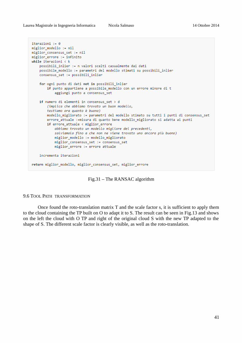
This method allows to reconstruct the transformation matrix T with a certain degree ofapproximation. To make the algorithm more efficient, the method just described is iterated severaltimes trying to maximize the number of inliers found.
Given a user-defined number of iterations k the method is iterated k times changing scalefactor in a neighborhood of s, the scale factor estimated initially. The code then becomes:
maxInliers = 0;for(i = -k; i < k; i++){
scale = s * (1 + i/k)Tr = Eigen::Matrix4f(Eigen::Matrix4f::Identity());Tr.topLeftCorner(3,3) *= Eigen::Matrix3f::Identity() * scale;pcl::transformPointCloud(*cloudS, cloudsS, Tr);
nInliers = computeRansac(cloudO, cloudsS, scale, T)
if(nInliers > maxInliers){
maxInliers = inLiers;Topt = T;
}}
At the end of the cycle will be identified scaling factor that maximizes the number of inliers.
40
Laurea Magistrale in Ingegneria Informatica Nicola Salmaso 14 Ottobre 2014
Fig.31 – The RANSAC algorithm
9.6 TOOL PATH TRANSFORMATION
Once found the roto-translation matrix T and the scale factor s, it is sufficient to apply themto the cloud containing the TP built on O to adapt it to S. The result can be seen in Fig.13 and showson the left the cloud with O TP and right of the original cloud S with the new TP adapted to theshape of S. The different scale factor is clearly visible, as well as the roto-translation.
41

Laurea Magistrale in Ingegneria Informatica Nicola Salmaso 14 Ottobre 2014
Fig. 32 – Tool Path Stretching. On the left the original TP, ont the stretched right the TP
9.7 A MORE GENERAL CASE
The problem with the approach set out in the preceding paragraphs is that it provides twoobjects that differ only by an affine transformation. The goal is instead to develop an algorithm toadapt a TP to a new object subject to various deformations. To this end it is necessary to have afunction that maps the points of the reference object in the corresponding points of the objectdeformed. The transformation can be divided into two components:
1. Global scale factor2. Local deformations
In particular, in case of absence of the second point, it falls in the assumptions made previously andthe algorithm of the global affine transformation allows to obtain the adaptation of the tool path.The algorithm in the general case treated in this section will therefore address the second point. LetO be the reference object, D the deformed object, TP the tool path defined on O and TP the tool pathdefined on D. The algorithm will then read O, D and TP and return TP' and it can be simplified asfollows:
1. Read O, D, TP (Fig.33) 2. Find the scale factor s using Principal Component Analysis 3. Build D '= sD getting an item with the proportions of D at the same scale of O 4. Use Iterative Closest Point to locate the global affine transformation T that sends sD in O 5. Apply T to D 'getting D' '(Fig.34) 6. At each point of TP associated with the point D '' a minimum distance 7. Apply the inverse transformation of T, and the scale factor of 1 / s to the points of D ''
identified 8. Build TP 'as the set of points thus calculated (Fig.35 and 36)
42

Laurea Magistrale in Ingegneria Informatica Nicola Salmaso 14 Ottobre 2014
Fig. 33 – Input : object model (in white) and object deformed and out of scale (in yellow)
Fig. 34 – Result of global affine transformation. The two objects, one in red and one in blue,overlap properly
43

Laurea Magistrale in Ingegneria Informatica Nicola Salmaso 14 Ottobre 2014
Fig. 35 – On the left the original TP, on the right the stretched TP
Fig. 36 – Some correspondences between TP and TP' highlighted by some green lines
44
Laurea Magistrale in Ingegneria Informatica Nicola Salmaso 14 Ottobre 2014
9.8 RESULTS
To test the TPS algorithm a software module wich implements it has been developed. Theinput data used are the result of the preprocessing procedures applied to cloud obtained in thescanning process. We have chosen the frames produced in series at different scales. Thedeformations were obtained in two different ways: by filing the edges of some frames and insertingnon-rigid sheets inside them.
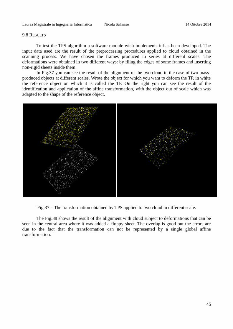
In Fig.37 you can see the result of the alignment of the two cloud in the case of two mass-produced objects at different scales. Wrote the object for which you want to deform the TP, in whitethe reference object on which it is called the TP. On the right you can see the result of theidentification and application of the affine transformation, with the object out of scale which wasadapted to the shape of the reference object.
Fig.37 – The transformation obtained by TPS applied to two cloud in different scale.
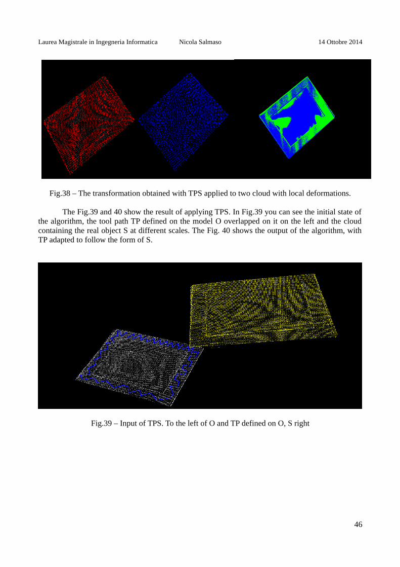
The Fig.38 shows the result of the alignment with cloud subject to deformations that can beseen in the central area where it was added a floppy sheet. The overlap is good but the errors aredue to the fact that the transformation can not be represented by a single global affinetransformation.
45
Laurea Magistrale in Ingegneria Informatica Nicola Salmaso 14 Ottobre 2014
Fig.38 – The transformation obtained with TPS applied to two cloud with local deformations.
The Fig.39 and 40 show the result of applying TPS. In Fig.39 you can see the initial state ofthe algorithm, the tool path TP defined on the model O overlapped on it on the left and the cloudcontaining the real object S at different scales. The Fig. 40 shows the output of the algorithm, withTP adapted to follow the form of S.
Fig.39 – Input of TPS. To the left of O and TP defined on O, S right
46

Laurea Magistrale in Ingegneria Informatica Nicola Salmaso 14 Ottobre 2014
Fig.40 – Output of TPS, with no local deformations. Note TP ' on the right.
Finally, Fig.41 shows the most general case in which the surface on which the TP has to beadapted is deformed. Some pairs of corresponding points are indicated by the green lines.
Fig.41 – Output of TPS, in the case of local deformations.
47

Laurea Magistrale in Ingegneria Informatica Nicola Salmaso 14 Ottobre 2014
CONCLUSIONS
The project was developed on behalf of and under the supervision of IT+Robotics under thename of SmartRange3D. In a first phase the set hereThe acquisition system and that ofcommunication have been developed and put into operation. The development of thecommunication system has required the construction of a hardware architecture and implementationof procedures and protocols able to put in communication the various elements between them. Forthe acquisition system has been designed, built and mounted a support bracket for fixing the cameraand the projectors to laser line to the manipulator robot. It was later developed a software modulecapable of acquiring by smart camera exploiting the integrated procedures for peak detection. Theelements of the acquisition system were then calibrated using appropriate procedures alreadydeveloped by IT+Robotics and the producers of the robot.
The communication and acquisition systems were then exploited for the creation of asoftware capable of performing calibration procedures and automatic scanning. To allow the three-dimensional reconstruction of scanned objects a mechanism called Pose-Frame Binder has beenimplemented, capable to associate to each frame acquired the camera position in the spatialcoordinates with respect to the chosen reference system.
The big advantage given by-frame poses binder is to be able to reconstruct a point cloudmore complete with the ability to rotate the acquisition system in a circular motion around theobject to be scanned to obtain a more complete overview of the same. In addition, the robotmanipulator while if set to move at a constant speed linear motion fails to fulfill an ideal motion andinterpolate the positions taken by it during the entire scan is due to error. In the case of the pose-frame binder positions are read in real time, eliminating the need to interpolate the positions and theconsequent interpolation error.
The ability to move the acquisition system commanding the manipulator via software libraryallows to improve the calibration cycle over that of having a system of extremely precisepositioning (the precision is given by the productive characteristics of the manipulator) allows therepeatability of the procedure. This is useful when you need to perform multiple calibrationsinvolving several acquisitions in the same positions as in the case of smart cameras and two lasers.In this case, just manually select the positions once and repeat the procedure of acquisition bychanging the mode of acquisition (from normal to peak detection) and turning on or off the bladeslaser according to need. The repeatability of the operation allows to test calibrations usingchessboard (or other objects) between them for different number of blocks and dimension in orderto obtain the best result of calibration.
The point cloud reconstructed with the Pose-Frame Binder were processed to isolate theindividual objects within each scan. It has therefore been designed and developed an algorithm thatsolves the problem of adaptive modification of tool paths to objects subject to deformation. In a firststep has been solved the problem of adapting the tool path to objects subject to a deformationrepresented by affine transformation. Finally, the algorithm has been adapted to the more generalcase of local deformations can not be represented by affine transformation.
The algorithm has been implemented in a testing software module and applied to the pointcloud obtained from the scan of some photo frames produced in series, some of the samedimensions, others on a different scale and with the same proportions and some strains due tofilings or the inclusion of a non-rigid sheet inside them. The algorithm was able to adapt the toolpath defined on an object model to all other deformed and / or out of scale objects used, followingthe correct surface in a manner consistent with how the path were defined.
48
Laurea Magistrale in Ingegneria Informatica Nicola Salmaso 14 Ottobre 2014
BIBLIOGRAPHY
R. Hartley and A. Zisserman, Multiple View Geometry in Computer Vision, Cambridge UniversityPress, 2000
J. Kannala, J. Heikkila, and S.S. Brandt, Geometrica camera calibration, Wiley Encyclopedia ofComputer Science and Engineering, 2008
P.Sturm et S.J. Maybank, On Plane-Based Camera Calibration : A Generale Algorithm,Singularities, Applications, IEE International Confercence on Computer Vision and PatternRecognition, pp. 423-437, 1999
J. F. i Colladio, New methods for triangulation-based shape acquisition using laser scanners,Ph.D. Thesys, Girona, 2004
Beyer, L.; Wulfsberg, J.: Practical Robot Calibration with ROSY. In: Robotica, Vol. 22, Cambridge2004, pp. 505–512.
Tagiyev, N.; Alizade, R.: A Forward and Reverse Displacement Analysis for a 6-DOF In-ParallelManipulator. In: Mech. Mach. Theory, Vol. 29, No. 1, London 1994, pp. 115–124.
Trevelyan, J. P.: Robot Calibration with a Kalman Filter. Presentation at International Conferenceon Advanced Robotics and Computer Vision (ICARCV96), Singapore 1996.
N.N.: ISO 9283 - Manipulating industrial robots. Performance criteria and related test methods.ISO, Geneva 1998.
Gottlieb , J.: Non-parametric Calibration of a Stewart Platform. In: Proceedings of 2014 Workshopon Fundamental Issues and Future Research Directions for Parallel Mechanisms and ManipulatorsJuly 7–8, 2014, Tianjin, China
H.S.M. Coxeter, Introduction to geometry , Wiley, 1961
Martin A. Fischler and Robert C. Bolles. Random Sample Consensus: A Paradigm for ModelFitting with Applications to Image Analysis and Automated Cartography. Comm. of the ACM 24(6): 381–395, 1981
David A. Forsyth and Jean Ponce. Computer Vision, a modern approach. Prentice Hall, 2003.
Richard Hartley and Andrew Zisserman. Multiple View Geometry in Computer Vision (2nd ed.).Cambridge University Press, 2003.
P.H.S. Torr and D.W. Murray The Development and Comparison of Robust Methods for Estimatingthe Fundamental Matrix. International Journal of Computer Vision 24 (3): 271–300., 1997
Ondrej Chum, Two-View Geometry Estimation by Random Sample and Consensus. PhD Thesis,2005
49