MASTER ATALOG - ref-sys.com
24
REFRIGERATION SYSTEMS MASTER CATALOG
Transcript of MASTER ATALOG - ref-sys.com

REFRIGERATION SYSTEMS
MASTER CATALOG
P.O. Box 1206 - Pryor, OK 74362 - (918) 825-7222 - Fax (800) 264-5329
R-MC-1203
We reserve the right to change or revise specifications and product design in connection with any feature of our products. Such changes do not entitle the buyer to corresponding changes, improvements, additions, or replacement for equipment previously sold or shipped.

2
Refrigeration Systems
Master Catalog
Table of Contents
Air Cooled Condensers ..........................................................4
Air Handling Units...................................................................5
CHILLERS
Air Cooled Chillers ............................................................6
Water Cooled Chillers .......................................................7
Evaporative Condenser Chillers .......................................8
COILS
Custom Coil Products .......................................................9
Booster Coils...................................................................10
Slip & Drive Booster Coils ...............................................11
CONDENSING UNITS
Semi-Hermetic Compressor Condensing Units .............12
Scroll Compressor Condensing Units............................14
Fluid Coolers ........................................................................15
Product Coolers ...................................................................16
Pump Packages ...................................................................17
UNIT COOLERS
Medium Profile Unit Coolers ...........................................18
Extended Low Velocity Unit Coolers ...............................19
Large Profile Unit Coolers...............................................20
Low Headroom Unit Coolers ...........................................21
Low Velocity Unit Coolers ...............................................22
Blast Freezer Unit Coolers ..............................................23
Blast Freezer Unit CoolersUnit Coolers for blast freezer and wet cooler
applications are designed to meet the rigors of the industrial refrigeration market. Cabinets are designed with corrosion resistant G-90 mill galvanized sheet metal. Cabinet structure is designed for ceiling or stacked floor mounting. Drain pans are insulated aluminum with factory supplied drain connection.
Optimum air flow and static requirements are efficiently addressed with the 28" heavy duty, efficient airfoil cast aluminum fan blade configuration, and fan icing is kept to a minimum due to the draw-through design.
Industrial duty three-phase, permanently lubricated fan motors with ball bearings are provided in either 11/2 horsepower (1140 RPM motors) or 3 horsepower (1750 RPM motors) selections to meet the most demanding static requirements.
These unit coolers are supplied with high efficiency, custom circuited heat transfer coils. Coils are manufac-tured with copper tubes and aluminum fins. Six, eight, and ten row coils are available. Five-fin-per-inch coils are available for blast chilling applications and four-fin-per-inch coils are available for blast freezing applications.
DRY SURFACE 3 HP 1,750 RPM Fans DRY SURFACE 1.5 HP 1,140 RPM Fans WET SURFACE 1.5 HP 1,140 RPM Fans
Model Number
0" External Static
Model Number
0" External Static
Model Number
0" External Static
CFMBTUH @
-20°F SSTCFM
BTUH @ -20°F SST
CFMBTUH @ 25°F SST
1 F
an
RBF-140-52-06 11,510 51,580
1 F
an
RBF-150-45-06 9,250 45,310
1 F
an
RBF-140-56-06 8,930 56,110
RBF-140-60-08 10,840 59,630 RBF-150-53-08 8,780 53,250 RBF-140-65-08 8,380 65,440
RBF-140-67-010 10,360 67,370 RBF-150-59-010 8,380 58,740 RBF-140-72-010 7,930 71,570
RBF-150-57-06 11,280 56,860 RBF-150-49-06 9,110 49,460 RBF-150-61-06 8,690 60,930
RBF-150-66-08 10,550 65,580 RBF-150-57-08 8,560 57,480 RBF-150-70-08 8,040 69,710
RBF-150-72-010 10,030 71,820 RBF-150-62-010 8,140 62,210 RBF-150-75-010 7,610 74,970
2 F
ans
RBF-240-103-06 23,030 103,150
2 F
ans
RBF-240-91-06 18,,510 90,610
2 F
ans
RBF-240-112-06 17,870 112,220
RBF-240-119-08 21,680 119,250 RBF-240-107-08 17,550 106,510 RBF-240-131-08 16,760 130,890
RBF-240-135-010 20,710 134,740 RBF-240-117-010 16,860 117,480 RBF-240-143-010 15,860 143,150
RBF-250-114-06 22,570 113,720 RBF-250-99-06 18,210 98,910 RBF-250-122-06 17,390 121,850
RBF-250-131-08 21,100 131,150 RBF-250-115-08 17,130 114,970 RBF-250-139-08 16,070 139,420
RBF-250-144-010 20,060 143,640 RBF-250-124-010 16,270 124,420 RBF-250-150-010 15,230 149,950
3 F
ans
RBF-340-145-06 33,450 144,140
3 F
ans
RBF-340-128-06 27,020 127,600
3 F
ans
RBF-340-157-06 25,820 156,670
RBF-340-166-08 30,980 166,300 RBF-340-148-08 25,140 147,970 RBF-340-181-08 23,800 181,140
RBF-340-187-010 29,430 187,330 RBF-340-163-010 23,800 163,260 RBF-340-198-010 22,350 197,910
RBF-350-158-06 32,670 157,570 RBF-350-140-06 26,330 140,060 RBF-350-169-06 24,850 168,980
RBF-350-182-08 30,090 181,730 RBF-350-160-08 24,410 159,880 RBF-350-193-08 22,680 192,800
RBF-350-198-010 28,330 198,210 RBF-350-173-010 23,300 172,860 RBF-350-207-010 21,350 207,210
4 F
ans
RBF-440-192-06 44,600 192,190
4 F
ans
RBF-440-170-06 36,020 170,220
4 F
ans
RBF-440-209-06 34,430 208,890
RBF-440-222-08 41,310 221,740 RBF-440-197-08 33,520 197,290 RBF-440-242-08 31,730 241,510
RBF-440-250-010 39,240 249,770 RBF-440-218-010 31,730 217,680 RBF-440-264-010 29,800 263,890
RBF-450-210-06 43,560 210,100 RBF-450-187-06 35,110 186,750 RBF-450-225-06 33,140 225,310
RBF-450-242-08 40,120 242,310 RBF-450-213-08 32,540 213,170 RBF-450-257-08 30,240 257,070
RBF-450-264-010 37,770 264,280 RBF-450-230-010 30,670 230,480 RBF-450-276-010 28,470 276,270
23
Dimensions: All units are 39 1/4" deep and 51 5/8" tall. Width of units: 1 fan = 61", 2 fans = 106", 3 fans = 136", 4 fan = 176".
Defrosting of the coils may be accomplished by electric defrost, air defrost, or 3 pipe hot gas defrost. The electric defrost is accomplished by chromate heaters designed specifically for the application. Heater location facilitates rapid defrost with less down time and quicker recovery. Air defrost may be used on blast chiller applications with less than 16 hours of run time per day and five-fin-per-inch coils. Hot gas defrost may be used on chiller freezer applications and is supplied with hot gas defrost drain pan.

RAE Corporation was founded in 1971, as a privately-held corporation. From the beginning, the company has been dedicated to the manufacturing of compressorized equipment for the refrigeration, HVAC, and industrial markets. Our manufacturing facilities are located in the 7,000-acre Mid-America Industrial Park, 40 miles east of Tulsa, Oklahoma. The low cost utilities, excellent labor resources, and central location of this site have contributed significantly to RAE Corporation's continuing success.
RAE Corporation remains a privately-held company, but today it functions with six divisions. Each of the six divisions are involved in the HVAC and
refrigeration industry. The divisions include Century Refrigeration, Refrigeration Systems, Technical Systems, RAE Coils, Air Cube, and King Coils. Thus Refrigeration Systems has the advantages of both a dedicated sales, marketing, and engineering group and a member of a larger, more diversified parent corporation.
Our corporate structure enables us to continue our history of personal involvement with each of our customers. By focusing attention on the refrigeration market, our sales representatives and engineers are able to develop a better understanding of the customer's specific needs. At the same time, we are able to draw on the financial security
and manufacturing strength of a much larger, closely integrated corporation.
All Refrigeration Systems equipment components are UL approved. Units are ETL certified and are built to ARI standards. Applicable products are NSF certified.
Refrigeration Systems is making a world of difference. We are helping to supply consumers with the freshest food products on the planet. Meat, dairy, fruits, vegetables, and a host of other perishable products are delivered fresh to millions of homes because of our commitment to excellence and our mastery of refrigeration technology.
Refrigeration Systems
322
Low Velocity Unit Coolers
CabinetCabinets are made of heavy gauge, rust-proof
smooth finish aluminum housing. All hardware is corrosion resistant. Full die-formed venturies minimize noise with maximum air throw. Fan guards are heavy gauge wire basket type coated for corrosion protection. Units mount flush to the ceiling for ease of wash down; no difficult areas above the unit to clean.
CoilCoils are copper tube, full collared die-formed
aluminum plate fin and tube sheets. Tubes are mechanically expanded for maximum heat transfer. Coils are leak tested at 175 psig under water. Flare connection type distributors have removable nozzles. Each nozzle is sized for the specified refrigerant and temperature range. All coils require external equalized expansion valve. Expansion valve is located within the cabinet. The expansion valve compartment is heated during the defrost cycle on electric defrost models.
FansFans have heavy duty aluminum blades, statically
and dynamically balanced for smooth operation. They are selected for quiet operation and maximum air throw.
Model Number*
DimensionsL" x W" x H"
Capacity (BTUH) at 10°TD**
CFM
20°F SST 35°F SST 50°F SST
RFCV-260-50 58” 287/8” 9” 5,450 5,875 6,320 950
RFCV-260-74 58” 287/8” 101/2” 8,066 8,695 9,354 1,200
RFCV-360-100 82” 287/8” 101/2” 10,900 11,750 12,640 1,825
RFCV-360-135 82” 287/8” 12” 14,715 15,863 17,064 2,175
RFCV-460-195 102” 287/8” 12” 21,255 22,913 24,648 3,390
RFCV-460-275 102” 287/8” 15” 29,975 32,313 34,760 4,500
MotorsMotors are permanently lubricated and suitable for
low temperature applications. All motors are thermally protected, 1550 RPM.
RefrigerantsAll coils are designed for use with refrigerants R-22
and R-404a. Specify which refrigerant when ordering.
ElectricalFactory prewired to terminal blocks located on end
of unit.
DefrostStandard unit is suitable for air defrost applications
(above 32°F room). Electric defrost models (below 32°F room) are available. Removable, low watt density resistance heaters, prewired with termination and fan delay controls.
Drain PanDrain pans are hinged for ease of access and
cleaning.
* All models require external equalized thermostatic expansion valve.
** To determine capacities at other TDs, divide capacities shown by 10 and then multiply by the desired TD.

4
Air Cooled Condensers
ApplicationsRefrigeration Systems Air Cooled Condensers are designed for commercial and industrial outdoor applications and utilize R-22 refrigerant. They come completely piped and wired, featuring a low profile and vertical air discharge. They also utilize a unique horizontal condenser coil design and high volume condenser fans. The design is unaffected by wind direction or extreme weather conditions.
Model NumberDimensionsL" x W" x H"
BTUH/1°
RC-AC104-H2 32" x 34" x 40" 1,852
RC-AC105-H2 32" x 34" x 40" 2,334
RC-AC106-H2 32" x 34" x 40" 2,952
RC-AC108-H2 51" x 34" x 40" 3,810
RC-AC109-H2 51" x 34" x 40" 4,228
RC-AC1010-H2 51" x 34" x 40" 4,652
RC-AC1011-H2 51" x 34" x 40" 5,377
RC-AC2014-H2 861/2" x 34" x 40" 6,816
RC-AC2018-H2 861/2" x 34" x 40" 8,701
RC-AC2021-H2 110" x 34" x 40" 10,512
RC-AC3028-H2 110" x 34" x 40" 13,531
RC-AC4034-H2 861/2" x 68" x 53" 16,616
RC-AC4037-H2 861/2" x 68" x 53" 18,386
RC-AC4042-H2 110" x 68" x 63" 21,023
RC-AC4047-H2 110" x 68" x 63" 23,281
RC-AC6055-H2 110" x 68" x 63" 27,063
RC-AC6068-H2 1441/2" x 88" x 63" 33,986
RC-AC6076-H2 1441/2" x 88" x 63" 37,864
RC-AC8084-H2 180" x 88" x 63" 41,862
RC-AC8092-H2 180" x 88" x 63" 45,967
RC-AC80112-H2 264" x 98" x 63" 55,676
RC-AC120136-H2 264" x 98" x 63" 67,810
RC-AC120150-H2 264" x 98" x 63" 75,001
RC-AC160162-H2 264" x 98" x 63" 80,962
Standard FeaturesCabinetCabinets are constructed entirely of mill galvanized sheet steel panels and formed structural members. All panels are removable for access and service.
MotorsMotors are industrial duty 1140 RPM, ball bearing,
weather resistant, three-phase with inherent electrical protection.
FansFans are of heavy duty steel with a corrosion
resistant coating.
Condenser CoilsCondenser coils are of seamless copper tube with
die-stamped aluminum plate fins, galvanized steel frames and tube sheets.
21
Low Headroom Unit Coolers
Model Number*Dimension Capacity (BTUH) at 10° TD** Fans
Width"*** 0°F SST 25°F SST CFM
4 F
PI
RFCL-240-63 423/4" 6,300 6,678 1,250
RFCL-240-79 423/4" 7,900 8,374 1,230
RFCL-340-95 593/4" 9,500 10,070 1,875
RFCL-340-122 593/4" 12,200 12,932 1,845
RFCL-440-160 753/4" 16,000 16,960 2,460
RFCL-540-202 923/4" 20,200 21,412 3,075
RFCL-640-240 1083/4" 24,000 25,440 3,690
5 F
PI
RFCL-250-74 423/4" 7,400 7,844 1,220
RFCL-250-96 423/4" 9,600 10,176 1,210
RFCL-350-114 593/4" 11,400 12,084 1,830
RFCL-350-146 593/4" 14,600 15,476 1,815
RFCL-450-192 753/4" 19,200 20,352 2,420
RFCL-550-240 923/4" 24,000 25,440 3,025
RFCL-650-288 1083/4" 28,800 30,528 3,630
6 F
PI
RFCL-260-83 423/4" 8,300 8,798 1,210
RFCL-260-106 423/4" 10,600 11,236 1,20
RFCL-360-126 593/4" 12,600 13,356 1,815
RFCL-360-161 593/4" 16,100 17,066 1,800
RFCL-460-213 753/4" 21,300 22,578 2,400
RFCL-560-267 923/4" 26,700 28,302 3,000
RFCL-660-317 1083/4" 31,700 33,602 3,600
8 F
PI (
a)
RFCL-280-92 423/4" 9,200 9,752 1,200
RFCL-280-118 423/4" 11,800 12,508 1,170
RFCL-380-140 593/4" 14,000 14,840 1,800
RFCL-380-180 593/4" 18,000 19,080 1,755
RFCL-480-238 753/4" 23,800 25,228 2,340
RFCL-580-300 923/4" 30,000 31,800 2,925
RFCL-680-355 1083/4" 35,500 37,630 3,510
* All models require external equalized thermostatic expansion valve.** To determine capacities at other TDs, divide capacities shown by 10 and then multiply by the desired TD.*** All units are 15 3/4" deep and 15 7/8" tall.
Applications• Walk-in Coolers / Freezers• Beverage Boxes / Produce Storage• Air Defrost 28 selections 6,678 to 37,985 BTUH 4, 5, 6, and 8 FPI Coils• Electric Defrost 21 Selections 6,174 to 33,919 BTUH 4, 5, and 6 FPI Coils
Features• Permanently lubricated motors, low noise level fans for high, medium, and low temperature refrigeration applications• 4, 5, 6, and 8 FPI spacing for accurate matching of loads• Easy access to controls, motors, and wiring.• Ceiling flush mount design• Hinged drain pans
Options• High Efficiency PSC Motors• Electric Defrost• Hot Gas Defrost• Insulated Drain Pans• Heated Drain Pans
(a) 8 FPI coils are not recommended for applications below +35°F room temperature.

5
Air Handling Units
Model Number Length"* Width"* Height"* Weight* CFM RangeNominal Capacity
Range (tons)RPAH-4 90" 38" 37.0" 1950 1,450 - 2,000 3.6 - 5.0RPAH-5 92" 46" 37.0" 2070 1,950 - 2,670 4.9 - 6.7RPAH-6 100" 50" 37.0" 2240 2,200 - 3,000 5.5 - 7.5RPAH-7 106" 60' 37.5" 2490 2,900 - 4,000 7.3 - 10.0RPAH-8 106" 64" 37.5" 2710 3,150 - 4,333 7.9 - 10.8
RPAH-10 112" 60" 46.5" 3110 3,900 - 5,333 9.8 - 13.3RPAH-11 116" 60" 49.5" 3250 4,350 - 6,000 10.9 - 15.0RPAH-12 116" 62" 52.5" 3400 4,850 - 6,667 12.1 - 16.7RPAH-15 124" 60" 61.5" 3780 5,800 - 8,000 14.5 - 20.0RPAH-18 142" 72" 61.5" 4740 7,500 - 10,000 18.8 - 25.0RPAH-22 142" 82" 61.5" 5110 8,500 - 12,000 21.3 - 30.0RPAH-24 148" 72" 75.5" 5490 9,000 - 12,500 22.5 - 31.3RPAH-28 152" 82" 75.5" 5980 11,000 - 15,000 27.5 - 37.5RPAH-32 162" 94" 78.0" 6800 12,500 - 17,500 31.3 - 43.8RPAH-38 172" 94" 90.0" 7670 15,000 - 21,000 37.5 - 52.5RPAH-44 176" 104" 90.0" 9050 17,500 - 24,000 43.8 - 60.0RPAH-50 184" 104" 102.0" 10140 20,000 - 28,000 50.0 - 70.0RPAH-58 192" 104" 114.0" 11140 24,000 - 32,000 60.0 - 80.0
Note: Air handlers include mixing box, pleated pre-filter w/frame, 6-row/10 fpi chilled water coil, FC fan with end discharge (listed in direction of air flow). Other optional components are available.
* All dimensions and weights are for standard construction. Consult factory for job specific information.
Model Number Nomenclature
R PAH - 20 - 6 - 10 - 0 - VL - H - W
R - RAEPackaged Air Handler
Coil Face AreaCoil Rows
Coil FPICompressor Rating
Coil Position
Temperature RangeMedium Used
Product Coolers and Packaged Air HandlersExample: R PAH -22 6 10 -0 VL -M W I II III IV V VI VII VIII IX
I – Basic Model R = RAE Corporation
II – Unit Type PAH = Packaged Air Handler
III – Area of Coil Face -08 to -45 = minimum 8 square feet to maximum 45 square feet
IV – Number of Coil Rows 4 = 4 rows 6 = 6 rows 8 = 8 rows
V – Density of Fins 4 to 14 = Minimum 4 fpi to maximum 14 fpi
VI – Compressor Rating -0 = No compressor
VII – Coil Position VL = Vertical, Left hand VR = Vertical, Right hand HL = Horizontal, Left hand HR = Horizontal, Right hand
VIII – Temperature Range -H = High -M = Medium -L = Low
IX – Medium Used 2 = R-22 7 = R-507 4 = R-404a O = Other 5 = R-502 W = Water
lllllll
ll
ll
ll
ll l l l l l l l l l l l l l l l
ll
ll
ll
lllllllllll
COIL BLOWER
FILTER RACK
20
Large Profile Unit CoolersAir Defrost• For cooler applications above +35°F• 24 models available 93,062 to 256,200 BTUH • Fin spacing at 4, 5, 6, or 8 per inch• 95 to 105 feet air throw
Electric Defrost• For cooler/freezer applications to -30°F operating
room temperature• 18 models available 62,550 to 226,900 BTUH • Fin spacing at 4, 5, or 6 per inch• 95 to 105 feet air throw• Insulated drain pan and adjustable defrost
termination/fan delay is standardCabinet
Cabinets are made of heavy gauge, rust-proof smooth finish aluminum housing. All hardware is corrosion resistant. Full die-formed venturies minimize noise with maximum air throw. Fan guards are heavy gauge wire basket type coated for corrosion protection.
Model Number
Width"* CFMCapacity
-40° SST 0° SST +30° SST
4 F
PI
RFCB-240-800 106” 14,600 62,550 83,908 94,587
RFCB-240-904 106” 15,800 71,832 96,630 108,624
RFCB-340-1046 136” 20,688 85,850 115,157 129,813
RFCB-340-1216 136” 22,650 99,800 133,843 150,877
RFCB-440-1395 176” 27,500 114,395 153,500 173,000
RFCB-440-1621 176” 30,200 132,922 178,400 201,100
5 F
PI
RFCB-250-889 106” 14,300 68,720 92,180 103,912
RFCB-250-997 106” 15,500 78,500 105,270 118,669
RFCB-350-1150 136” 20,100 94,300 126,500 142,600
RFCB-350-1325 136” 22,050 108,700 145,778 164,331
RFCB-450-1533 176” 26,800 125,760 168,000 190,100
RFCB-450-1767 176” 29,400 144,894 194,300 219,100
6 F
PI
RFCB-260-912 106” 13,600 N/A 94,723 106,779
RFCB-260-1067 106” 15,200 N/A 111,012 125,141
RFCB-360-1200 136” 19,350 N/A 132,000 148,800
RFCB-360-1395 136” 21,600 N/A 153,450 172,980
RFCB-460-1600 176” 25,800 N/A 176,000 198,400
RFCB-460-1860 176” 28,800 N/A 204,600 230,600
8 F
PI
RFCB-280-1006 106” 13,500 N/A N/A 116,064
RFCB-280-1145 106” 15,000 N/A N/A 134,490
RFCB-380-1280 136” 19,050 N/A N/A 158,720
RFCB-380-1550 136” 21,450 N/A N/A 192,200
RFCB-480-1707 176” 25,400 N/A N/A 211,600
RFCB-480-2067 176” 28,600 N/A N/A 256,200
CoilCoils are copper tube, full collared die-
formed aluminum plate fin and tube sheets. Tubes are mechanically expanded for maximum heat transfer. Coils are leak tested at 350 psig under water. Solder and flare type distributors have removable nozzles. Each nozzle is sized for the specified refrigerant and temperature range. All coils require external equalized expansion valve. Expansion valve is located within the cabinet. The expansion valve compartment is heated during the defrost cycle on electric defrost models.
FansFans have heavy duty steel blades and hubs,
statically and dynamically balanced for smooth operation. They are selected for maximum air throw.
MotorsMotors are permanently lubricated and
suitable for low temperature applications. Motors are heavy duty, high efficiency, full ball bearing and have internal thermal overloads. Fan motors are pre-wired to terminal blocks.
RefrigerantsAll coils are designed for use with many
refrigerants.Electric Defrost models include pre-wired
terminal blocks, low watt density heaters, housed internal to the coil for a rapid and efficient defrost. Lower coil and drain pan heater provides fast and reliable condensate drain. Standard operating control includes an adjustable defrost termination with fan delay.
MountingThe standard mounting configuration is
ceiling hung, but optional floor mounting is available.
*All units are 34" deep and 42 5/8" tall.
6
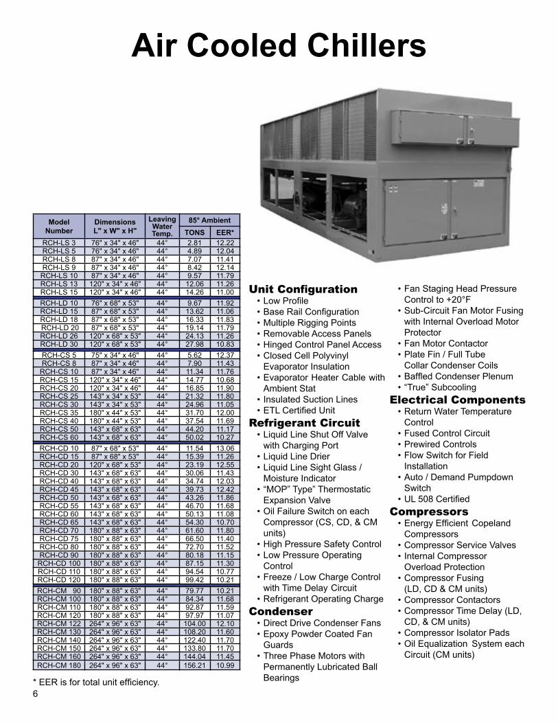
Air Cooled Chillers
Unit Configuration• Low Profile• Base Rail Configuration• Multiple Rigging Points• Removable Access Panels• Hinged Control Panel Access• Closed Cell Polyvinyl
Evaporator Insulation• Evaporator Heater Cable with
Ambient Stat• Insulated Suction Lines• ETL Certified Unit
Refrigerant Circuit• Liquid Line Shut Off Valve
with Charging Port• Liquid Line Drier• Liquid Line Sight Glass /
Moisture Indicator• “MOP” Type” Thermostatic
Expansion Valve• Oil Failure Switch on each
Compressor (CS, CD, & CM units)
• High Pressure Safety Control• Low Pressure Operating
Control• Freeze / Low Charge Control
with Time Delay Circuit• Refrigerant Operating Charge
Condenser• Direct Drive Condenser Fans• Epoxy Powder Coated Fan
Guards• Three Phase Motors with
Permanently Lubricated Ball Bearings
• Fan Staging Head Pressure Control to +20°F
• Sub-Circuit Fan Motor Fusing with Internal Overload Motor Protector
• Fan Motor Contactor • Plate Fin / Full Tube
Collar Condenser Coils• Baffled Condenser Plenum• “True” Subcooling
Electrical Components• Return Water Temperature
Control• Fused Control Circuit• Prewired Controls• Flow Switch for Field
Installation• Auto / Demand Pumpdown
Switch• UL 508 Certified
Compressors• Energy Efficient Copeland
Compressors• Compressor Service Valves• Internal Compressor
Overload Protection• Compressor Fusing
(LD, CD & CM units)• Compressor Contactors• Compressor Time Delay (LD,
CD, & CM units)• Compressor Isolator Pads• Oil Equalization System each
Circuit (CM units)
Model Number
DimensionsL" x W" x H"
Leaving Water Temp.
85° Ambient
TONS EER*
RCH-LS 3 76" x 34" x 46" 44° 2.81 12.22RCH-LS 5 76" x 34" x 46" 44° 4.89 12.04RCH-LS 8 87" x 34" x 46" 44° 7.07 11.41RCH-LS 9 87" x 34" x 46" 44° 8.42 12.14
RCH-LS 10 87" x 34" x 46" 44° 9.57 11.79RCH-LS 13 120" x 34" x 46" 44° 12.06 11.26RCH-LS 15 120" x 34" x 46" 44° 14.26 11.00
RCH-LD 10 76" x 68" x 53" 44° 9.67 11.92RCH-LD 15 87" x 68" x 53" 44° 13.62 11.06RCH-LD 18 87" x 68" x 53" 44° 16.33 11.83 RCH-LD 20 87" x 68" x 53" 44° 19.14 11.79RCH-LD 26 120" x 68" x 53" 44° 24.13 11.26RCH-LD 30 120" x 68" x 53" 44° 27.98 10.83
RCH-CS 5 75" x 34" x 46" 44° 5.62 12.37RCH-CS 8 87" x 34" x 46" 44° 7.90 11.43
RCH-CS 10 87" x 34" x 46" 44° 11.34 11.76RCH-CS 15 120" x 34" x 46" 44° 14.77 10.68RCH-CS 20 120" x 34" x 46" 44° 16.85 11.90RCH-CS 25 143" x 34" x 53" 44° 21.32 11.80RCH-CS 30 143" x 34" x 53" 44° 24.96 11.05RCH-CS 35 180" x 44" x 53" 44° 31.70 12.00RCH-CS 40 180" x 44" x 53" 44° 37.54 11.69RCH-CS 50 143" x 68" x 63" 44° 44.20 11.17RCH-CS 60 143" x 68" x 63" 44° 50.02 10.27
RCH-CD 10 87" x 68" x 53" 44° 11.54 13.06RCH-CD 15 87" x 68" x 53" 44° 15.39 11.26RCH-CD 20 120" x 68" x 53" 44° 23.19 12.55RCH-CD 30 143" x 68" x 63" 44° 30.06 11.43RCH-CD 40 143" x 68" x 63" 44° 34.74 12.03RCH-CD 45 143" x 68" x 63" 44° 39.73 12.42RCH-CD 50 143" x 68" x 63" 44° 43.26 11.86RCH-CD 55 143" x 68" x 63" 44° 46.70 11.68RCH-CD 60 143" x 68" x 63" 44° 50.13 11.08RCH-CD 65 143" x 68" x 63" 44° 54.30 10.70RCH-CD 70 180" x 88" x 63" 44° 61.60 11.80RCH-CD 75 180" x 88" x 63" 44° 66.50 11.40RCH-CD 80 180" x 88" x 63" 44° 72.70 11.52RCH-CD 90 180" x 88" x 63" 44° 80.18 11.15
RCH-CD 100 180" x 88" x 63" 44° 87.15 11.30RCH-CD 110 180" x 88" x 63" 44° 94.54 10.77RCH-CD 120 180" x 88" x 63" 44° 99.42 10.21
RCH-CM 90 180" x 88" x 63" 44° 79.77 10.21RCH-CM 100 180" x 88" x 63" 44° 84.34 11.68RCH-CM 110 180" x 88" x 63" 44° 92.87 11.59RCH-CM 120 180" x 88" x 63" 44° 97.97 11.07RCH-CM 122 264" x 96" x 63" 44° 104.00 12.10RCH-CM 130 264" x 96" x 63" 44° 108.20 11.60RCH-CM 140 264" x 96" x 63" 44° 122.40 11.70RCH-CM 150 264" x 96" x 63" 44° 133.80 11.70RCH-CM 160 264" x 96" x 63" 44° 144.04 11.45RCH-CM 180 264" x 96" x 63" 44° 156.21 10.99
* EER is for total unit efficiency.19
Extended Low Velocity Unit CoolersAir, Electric, or Hot Gas Defrost
• 4,000 to 20,000 CFM
• 16,000 to 152,000 BTUH
Model Number
DimensionsL" x W" x H"
FansQty.
CFMCapacity
0° SST +25° SST
4 F
PI
RFCV-140-175 561/4" x 521/2" x 231/4" 1 3,975 16,100 17,870
RFCV-140-211 561/4" x 521/2" x 231/4" 1 3,890 19,410 21,540
RFCV-240-349 961/4" x 521/2" x 231/4" 2 7,950 32,100 35,640
RFCV-240-422 961/4" x 521/2" x 231/4" 2 7,785 38,820 43,090
RFCV-340-523 1361/4" x 521/2" x 231/4" 3 11,925 48,120 53,410
RFCV-340-633 1361/4" x 521/2" x 231/4" 3 11,675 58,240 64,650
RFCV-440-698 1761/4" x 521/2" x 231/4" 4 15,900 64,220 71,280
RFCV-440-844 1761/4" x 521/2" x 231/4" 4 15,560 77,650 86,190
RFCV-540-872 2161/4" x 521/2" x 231/4" 5 19,870 80,220 89,040
RFCV-540-1055 2161/4" x 521/2" x 231/4" 5 19,460 97,060 107,740
5 F
PI
RFCV-150-197 561/4" x 521/2" x 231/4" 1 3,950 18,130 20,120
RFCV-150-236 561/4" x 521/2" x 231/4" 1 3,863 21,710 24,100
RFCV-250-393 961/4" x 521/2" x 231/4" 2 7,896 36,160 40,140
RFCV-250-472 961/4" x 521/2" x 231/4" 2 7,725 43,420 48,200
RFCV-350-590 1361/4" x 521/2" x 231/4" 3 11,844 54,280 60,250
RFCV-350-709 1361/4" x 521/2" x 231/4" 3 11,588 65,230 72,410
RFCV-450-786 1761/4" x 521/2" x 231/4" 4 15,792 72,310 80,260
RFCV-450-945 1761/4" x 521/2" x 231/4" 4 15,450 86,940 96,500
RFCV-550-983 2161/4" x 521/2" x 231/4" 5 19,740 90,440 100,400
RFCV-550-1180 2161/4" x 521/2" x 231/4" 5 19,313 108,560 120,500
6 F
PI
RFCV-160-209 561/4" x 521/2" x 231/4" 1 3,921 19,230 21,350
RFCV-160-251 561/4" x 521/2" x 231/4" 1 3,832 23,090 25,630
RFCV-260-417 961/4" x 521/2" x 231/4" 2 7,841 28,260 42,580
RFCV-260-502 961/4" x 521/2" x 231/4" 2 664 46,180 51,260
RFCV-360-626 1361/4" x 521/2" x 231/4" 3 11,762 57,590 63,920
RFCV-360-752 1361/4" x 521/2" x 231/4" 3 11,496 69,180 76,790
RFCV-460-834 1761/4" x 521/2" x 231/4" 4 15,682 76,730 85,170
RFCV-460-1003 1761/4" x 521/2" x 231/4" 4 15,328 92,280 102,430
RFCV-560-1043 2161/4" x 521/2" x 231/4" 5 19,603 95,960 106,520
RFCV-560-1254 2161/4" x 521/2" x 231/4" 5 19,160 115,370 128,060
8 F
PI
RFCV-180-229 561/4" x 521/2" x 231/4" 1 3,863
Not rated for use in this
range.
23,390
RFCV-180-266 561/4" x 521/2" x 231/4" 1 3,735 27,160
RFCV-280-457 961/4" x 521/2" x 231/4" 2 7,725 46,670
RFCV-280-532 961/4" x 521/2" x 231/4" 2 7,469 54,330
RFCV-380-636 1361/4" x 521/2" x 231/4" 3 11,588 70,050
RFCV-380-800 1361/4" x 521/2" x 231/4" 3 11,204 81,700
RFCV-480-915 1761/4" x 521/2" x 231/4" 4 15,450 93,440
RFCV-480-1056 1761/4" x 521/2" x 231/4" 4 14,938 108,760
RFCV-580-1143 2161/4" x 521/2" x 231/4" 5 19,313 116,720
RFCV-580-1331 2161/4" x 521/2" x 231/4" 5 18,673 135,920
Applications
• Meat Cutting / Prep Rooms• Holding / Packing Rooms• Florist Boxes• High Humidity - Low TD
Features
• Low Air Velocity• Two Way Air Throw• Prewired, Thermal Protected Motors• Ceiling Flush Mount Design• Hinged Drain Pan
Options
• Electric Defrost• Hot Gas Defrost• Insulated Drain Pans• Stainless Steel Hardware• Stainless Steel Drain pan• Stainless Steel Cabinet• Acrycoat or Copper Fins

7
Water Cooled Chillers
Standard Features• Narrow Profile• Structural Supports• Hinged Control Panel Access• Painted Enamel Unit• Liquid Line Shut Off Valve with Charging Port• Oil Failure Switch/Each Compressor
(CS, CD & CM Series)• High Pressure Safety Control• Low Pressure Operating Control• Refrigerant Operating Charge• Fused Control Circuit• Prewired Controls• Auto/Demand Pumpdown Switch• Flow Switch (Shipped Loose)• Manual Lead/Lag Switch (LD, CD, CM Series)• Freeze Stat - Pressure Sensing
Low Pressure Safety• Compressor Service Valves• Energy Efficient Copeland Compressors• Internal Compressor Overload Protection (All 3
Windings)• Compressor Fusing (LD, CD & CM Series)• Crankcase Heaters• Compressor Contactors• Time Delay Compressor Start (LD, CD & CM Series)• Compressor Isolator Pads• Oil Equalization system For Each Circuit (CM Series)• MOP Expansion Valves• NEMA 3 UL 508 Labeled Electrical Panel• Microelectronic Return Water Temperature Control• Replaceable Core Driers (CM Series Only)
Model NumberDimensionsL" x W" x H"
Leaving Water
Temperature
85° Ambient
TONS EER**
RWCH-LS 3 60" x 35" x 27" 44° 2.91 19.16RWCH-LS 5 60" x 35" x 27" 44° 4.99 16.86RWCH-LS 8 60" x 35" x 27" 44° 7.38 16.78RWCH-LS 9 60" x 35" x 27" 44° 8.63 15.87
RWCH-LS 10 60" x 35" x 27" 44° 9.67 15.30RWCH-LS 13 60" x 35" x 27" 44° 12.17 15.36RWCH-LS 15 60" x 35" x 27" 44° 14.46 14.81
RWCH-LD 10 70" x 35" x 36" 44° 10.09 17.27RWCH-LD 15 70" x 35" x 36" 44° 14.56 16.70RWCH-LD 18 70" x 35" x 36" 44° 17.26 15.87RWCH-LD 20 70" x 35" x 36" 44° 20.18 15.75RWCH-LD 26 70" x 35" x 36" 44° 24.86 15.61RWCH-LD 30 70" x 35" x 36" 44° 28.50 14.66
RWCH-CS 5 59" x 35" x 421/2" 44° 6.24 18.57RWCH-CS 8 59" x 35" x 421/2" 44° 8.42 16.45
RWCH-CS 10 621/2" x 35" x 421/2" 44° 11.65 15.01RWCH-CS 15 621/2" x 35" x 441/2" 44° 15.29 14.16RWCH-CS 20 66" x 35" x 441/2" 44° 17.68 16.49RWCH-CS 25 66" x 35" x 441/2" 44° 22.26 15.72RWCH-CS 30 66" x 35" x 441/2" 44° 25.58 14.28RWCH-CS 35 91" x 35" x 57" 44° 34.11 14.31RWCH-CS 40 91" x 35" x 57" 44° 40.14 15.39RWCH-CS 50 91" x 35" x 57" 44° 45.86 13.88RWCH-CS 60 91" x 35" x 57" 44° 53.35 12.95
RWCH-CD 10 76" x 35" x 63" 44° 11.54 15.52RWCH-CD 15 70" x 35" x 65" 44° 16.85 16.58RWCH-CD 20 80" x 35" x 65" 44° 23.82 15327RWCH-CD 30 80" x 35" x 67" 44° 30.06 14.02RWCH-CD 40 106" x 35" x 72" 44° 37.34 17.10RWCH-CD 45 106" x 35" x 72" 44° 41.18 16.08RWCH-CD 50 106" x 35" x 82" 44° 45.66 15.99RWCH-CD 55 106" x 35" x 82" 44° 49.82 15.38RWCH-CD 60 106" x 35" x 82" 44° 53.04 14.67RWCH-CD 65 106" x 35" x 84" 44° 60.11 14.73RWCH-CD 70 106" x 35" x 84" 44° 66.04 14.04RWCH-CD 75 106" x 35" x 84" 44° 70.31 14.00RWCH-CD 80 106" x 35" x 84" 44° 76.86 14.99RWCH-CD 90 106" x 40" x 88" 44° 83.20 14.25
RWCH-CD 100 106" x 40" x 91" 44° 91.21 13.82RWCH-CD 110 106" x 40" x 91" 44° 99.22 13.57RWCH-CD 120 106" x 40" x 91" 44° 105.46 12.85
RWCH-CM 90 142" x 35" x 89" 44° 82.27 14.92RWCH-CM 100 142" x 35" x 89" 44° 89.23 15.05RWCH-CM 110 142" x 35" x 89" 44° 97.03 15.07RWCH-CM 120 142" x 42" x 89" 44° 102.86 14.33RWCH-CM 130 142" x 42" x 91" 44° 119.70 14.53RWCH-CM 140 142" x 42" x 91" 44° 129.90 13.64RWCH-CM 150 142" x 42" x 91" 44° 140.40 14.21RWCH-CM 160 142" x 42" x 91" 44° 148.72 14.20RWCH-CM 180 154" x 42" x 89" 44° 161.0 13.2RWCH-CM 200 154" x 42" x 89" 44° 175.0 13.2RWCH-CM 220 154" x 42" x 89" 44° 192.1 12.6RWCH-CM 240 154" x 42" x 89" 44° 207.0 12.2
18
Medium Profile Unit Coolers
* All units are 26" deep and 30 15/16" tall. ** Capacity based on R-22.
AIR DEFROST ELECTRIC DEFROSTModel
Number Width* CFMCapacity** Model
Number Width* CFMCapacity**
+25° SST +45° SST -40° SST 0° SST +25° SST
5 F
PI
RFCA-150YA-140 46" 3,270 17,934 20,087
4 F
PI
RFCA-140YE-126 46" 3,310 10,332 13,860 15,372
RFCA-150YA-153 46" 3,930 19,600 N/A RFCA-140YE-137 46" 4,030 11,234 15,070 16,715
RFCA-150YA-185 46" 3,170 23,699 26,542 RFCA-140YE-169 46" 3,220 13,520 18,590 20,618
RFCA-150YA-206 46" 3,784 26,389 29,555 RFCA-140YE-185 46" 3,810 15,170 20,350 22,570
RFCA-250YA-281 76" 6,540 35,996 40,316 RFCA-240YE-253 76" 6,630 20,746 27,830 30,866
RFCA-250YA-307 76" 7,860 39,327 N/A RFCA-240YE-275 76" 8,060 22,500 30,250 33,550
RFCA-250YA-371 76" 6,340 47,525 53,228 RFCA-240YE-338 76" 6,440 27,716 37,180 41,236
RFCA-250YA-413 76" 7,568 52,905 57,154 RFCA-240YE-371 76" 7,620 30,422 40,810 45,262
RFCA-350YA-422 106" 9,810 54,071 60,560 RFCA-340YE-379 106" 9,940 31,078 41,690 46,238
RFCA-350YA-461 106" 11,790 59,054 N/A RFCA-340YE-413 106" 12,090 33,866 45,430 50,386
RFCA-350YA-556 106" 9,510 71,288 79,842 RFCA-340YE-507 106" 9,750 41,574 55,770 61,854
RFCA-350YA-620 106" 11,352 79,422 88,,953 RFCA-340YE-556 106" 11,430 45,592 61,160 67,832
RFCA-450YA-745 136" 12,680 95,499 106,958 RFCA-440YE-679 136" 12,970 55,678 74,690 82,838
RFCA-450YA-830 136" 15,208 106,323 119,082 RFCA-440YE-745 136" 15,240 61,090 81,950 90,890
RFCA-450YA-925 136" 15,920 118,493 132,712 RFCA-440YE-841 136" 16,120 68,962 92,510 102,602
6 F
PI
RFCA-160YA-150 46" 3,260 19,764 22,135
5 F
PI
RFCA-150YE-140 46" 3,270 12,054 16,170 17,934
RFCA-160YA-164 46" 3,880 21,608 N/A RFCA-150YE-153 46" 3,930 13,173 17,672 19,600
RFCA-160YA-193 46" 3,050 25,430 28,482 RFCA-150YE-185 46" 3,170 15,929 21,368 23,699
RFCA-160YA-212 46" 3,760 27,933 31,285 RFCA-150YE-206 46" 3,784 17,737 23,793 26,389
RFCA-260YA-301 76" 6,520 39,660 44,419 RFCA-250YE-281 76" 6,540 24,194 32,456 35,996
RFCA-260YA-328 76" 7,760 43,217 N/A RFCA-250YE-307 76" 7,860 26,433 35,459 39,327
RFCA-260YA-387 76" 6,100 50,991 57,110 RFCA-250YE-371 76" 6,340 31,943 42,851 47,525
RFCA-260YA-424 76" 7,520 55,869 62,570 RFCA-250YE-413 76" 7,568 35,559 47,702 52,905
RFCA-360YA-451 106" 9,780 59,424 66,555 RFCA-350YE-422 106" 9,810 36,343 48,753 54,071
RFCA-360YA-492 106" 11,640 64,826 N/A RFCA-350YE-461 106" 11,790 36,692 53,246 59,054
RFCA-360YA-581 106" 9,150 76,553 85,739 RFCA-350YE-556 106" 9,510 47,915 64,276 71,288
RFCA-360YA-636 106" 11,280 83,799 93,855 RFCA-350YE-620 106" 11,352 53,382 71,610 79,422
RFCA-460YA-779 136" 12,200 102,641 114,958 RFCA-450YE-745 136" 12,680 64,188 86,105 95,499
RFCA-460YA-852 136" 15,040 112,260 125,730 RFCA-450YE-830 136" 15,208 71,463 95,865 106,323
RFCA-460YA-978 136" 15,536 128,861 144,324 RFCA-450YE-925 136" 15,920 79,643 106,838 118,493
8 F
PI
RFCA-180YA-165 46" 3,160 22,143 24,800
6 F
PI
RFCA-160YE-150 46" 3,260
Not rated for use in this range.
17,820 19,754
RFCA-180YA-208 46" 2,950 27,914 31,263 RFCA-160YE-164 46" 3,880 19,483 21,609
RFCA-280YA-330 76" 6,320 44,286 49,600 RFCA-160YE-193 46" 3,050 22,928 25,430
RFCA-280YA-417 76" 5,900 55,961 62,678 RFCA-160YE-212 46" 3,760 25,186 27,933
RFCA-380YA-495 106" 9,480 66,429 74,401 RFCA-260YE-301 76" 6,520 35,759 39,660
RFCA-380YA-626 106" 8,850 84,009 94,091 RFCA-260YE-328 76" 7,760 38,966 43,217
RFCA-480YA-839 136" 11,800 112,594 126,105 RFCA-260YE-387 76" 6,100 45,976 50,992
RFCA-480YA-1050 136" 15,132 140,910 157,819 RFCA-260YE-424 76" 7,520 50,371 55,869
RFCA-360YE-451 106" 9,780 53,578 59,424
RFCA-360YE-492 106" 11,640 58,450 64,826
RFCA-360YE-581 106" 9,150 69,023 76,533
RFCA-360YE-636 106" 11,280 75,555 83,799
RFCA-460YE-779 136" 12,200 92,545 102,641
RFCA-460YE-852 136" 15,040 101,548 112,269
RFCA-460YE-978 136" 15,536 116,186 128,869
Air Defrost - Cooler applications above +35°F• 38 models available 17,934 to 160,639 BTUH • Fin spacing at 5, 6, or 8 per inch
Electric Defrost - Cooler/Freezer applications to -30°F operating room temperature
• 45 models available 10,332 to 128,869 BTUH • Fin spacing at 4, 5, or 6 per inch• 60 to 70 feet air throw• Insulated drain pan and adjustable defrost termination/fan delay is standard.

Evaporative Condenser Chillers
8
Model Number
Length Width Height LWT78°F WB
Power Source - One Power Source - Two
MCA MAX FUSE MCA MAX FUSE
Tons*KW/
Ton** 208v 230v 460v 208v 230v 460v 208v 230v 460v 208v 230v 460v
RECH-SS60 120" 96" 102" 44° 69.9 0.934 282 279.0 136.4 450 450 110 – – – – – –
RECH-SD80 122" 96" 102" 44° 93.5 0.874 330 327.7 158.2 450 450 200 – – – – – –
RECH-SD120 162" 96" 102" 44° 137.7 0.914 291.2 287.8 239.8 450 450 220 253.8 253.8 123.8 450 450 200
RECH-SD150 175" 96" 109" 44° 174.0 0.887 371.6 336.4 236.5 600 500 400 318.8 288.4 212.5 500 500 350
RECH-SD200 248" 96" 102" 44° 197.7 0.867 390.8 353.0 241.5 600 600 400 390.8 353.0 241.5 600 600 400
RECH-SM200 248" 96" 102" 44° 220.8 0.927 402.3 350.0 193.1 500 500 250 402.3 350.0 193.1 500 500 250
RECH-SM240 248" 96" 102" 44° 270.4 0.967 492.2 489.0 238.9 600 600 300 492.2 489.0 238.9 600 600 300
RECH-SM300 328" 96" 109" 44° 343.8 0.900 611.2 553.0 399.5 800 700 500 611.2 553.0 399.5 800 700 500
Unit Configuration• Single Piece Construction• Base Rail Configuration• Multiple Rigging Points• Removable Access Panels• Hinged Control Panel Access• Closed Cell Polyvinyl
Evaporator Insulation• Evaporator Heater Cable with Ambient Stat• Insulated Suction Lines• ETL Certified Unit
Refrigerant Circuit• Liquid Line Shut Off Valve
with Charging Port• Liquid Line Drier
(Replaceable Core)• Liquid Line Sight Glass /
Moisture Indicator• “MOP” Type” Thermostatic
Expansion Valve• High Pressure Safety Control• Low Pressure Operating
Control• Freeze / Low Charge Control
with Time Delay Circuit• Refrigerant Operating Charge
Evaporative Condenser• Three Phase TEFC Motors
with Permanently Lubricated Ball Bearings
• Fan Motor Contactor • Non-Clog Water Diffusers• PVC Eliminators
Electrical Components• Return Water Temperature Control• Fused Control Circuit• Prewired Controls• Flow Switch for Field
Installation• Auto / Demand Pumpdown Switch• UL 508 Certified• Phase Failure Protection
Compressors• Semi-Hermatic Screw Compressors• Compressor Service Valves• Compressor Overload Protection• Compressor Fusing • Compressor Contactors• Compressor Time Delay• Compressor Isolator Pads• Oil Equalization System Each Circuit
(CM units)
* Based on ARI Standard 590-92.** KW is based on total unit power.
17
Pump Packages
Model Number
Pump Quantity
Flow RangeDimensions L" x W" x H"
OperatingWeight
50' Total System Head*
100' Total System Head*
Motor Horsepower
Pump Speed RPM
Motor Horsepower
Pump Speed RPM
RPS-20 1 1-20 GPM 48" x 36" x 48" 840 lbs. 1 1750 — —
RPS-45 1 21-45 GPM 48" x 36" x 48" 1,140 lbs. 2 1750 5 1750
RPS-80 1 46-80 GPM 60" x 36" x 48" 1,425 lbs. 3 1750 5 3500
RPS-130 1 81-130 GPM 72" x 36" x 60" 1,620 lbs. 5 1750 7.5 3500
RPS-200 1 131-200 GPM 72" x 48" x 66" 2,040 lbs. 5 3500 10 3500
RPS-350 1 201-350 GPM 84" x 48" x 66" 2,660 lbs. 7.5 3500 15 3500
RPS-600 1 351-600 GPM 96" x 60" x 72" 3,410 lbs. 10 3500 20 3500
RPS-800 1 601-800 GPM 96" x 84" x 72" 4,760 lbs. 15 3500 25 3500
RPD-20 2 1-20 GPM 48" x 42" x 48" 1,330 lbs. 1 1750 — —
RPD-45 2 21-45 GPM 48" x 42" x 48" 1,470 lbs. 2 1750 5 1750
RPD-80 2 46-80 GPM 60" x 48" x 48" 1,650 lbs. 3 1750 5 3500
RPD-130 2 81-130 GPM 72" x 60" x 60" 1,955 lbs. 5 1750 7.5 3500
RPD-200 2 131-200 GPM 72" x 60" x 66" 2,285 lbs. 5 3500 10 3500
RPD-350 2 201-350 GPM 84" x 60" x 66" 3,010 lbs. 7.5 3500 15 3500
RPD-600 2 351-600 GPM 96" x 84" x 72" 5,040 lbs. 10 3500 20 3500
RPD-800 2 601-800 GPM 96" x 84" x 72" 5,880 lbs. 15 3500 25 3500
* Total head includes a 15' internal drop for pump package.
Standard Features• Close-coupled, end-suction, centrifugal pumps• Mounted and wired pump starters• Hand-Off-Auto switch for each pump• Pump selector switch on dual pump packages only• Mounted and wired paddle-type flow switch• Isolation valve on suction side of pump
(ball-type valve through 2 1/2” pipe size, butterfly-type valve 3” pipe size and up)
• Strainer installed on suction side of pump (wye strainer through 3”, basket strainer 4” and up)
• Vertical scale Fahrenheit thermometers• Dial-type differential pressure gauge with shutoff
valves across the pump• Dielectric unions at each dissimilar metal connection• 1/2” closed cell insulation on all piping and
components• Structural steel base rail configuration• Corrosion resistant epoxy coating• NEMA 3R hinged door control panel with UL 508 label• Automatic switchover to standby pump based on flow
or overload failure (dual pump packages only)

Whether standard or custom engineered, Refrigeration Systems' heat transfer coils offer the optimum in efficiency, long life, and quality design. Refrigeration Systems' coils are manufactured in our facility and we take pride in putting our label on the finished product. Our experience, engineering, and commitment to excellence make Refrigeration Systems a leading supplier of heat transfer coils for all your HVAC needs. Each component of a Refrigeration Systems' coil is selected and engineered to provide the best and most versatile coil possible.
Series 12Tubes:1/2" O.D. X .017" copper tube wall thickness is standard. Tube wall thickness may be optionally provided as .025", and .032".
Fins:Die-formed tempered aluminum, copper, or acrylic coated fins with extruded fin collars provide maximum heat transfer and accurate fin spacing. Utilizing a 1.25" equilateral triangle design in a staggered pattern, the fins are available with corrugated or flat surfaces of .006", .008", and .010" thickness.
Series 58Tubes:5/8" O.D. X .020" copper tube wall thickness is standard. Tube wall thickness may be optionally provided as .025", .035", and .049".
Fins:Die-formed tempered aluminum, copper, or acrylic coated fins with extruded fin collars provide maximum heat transfer and accurate fin spacing. Utilizing a 1.5" equilateral triangle design in a staggered pattern, the fins are available with corrugated or flat surfaces of .006", .008", and .010" thickness.
Series 11 Tubes:1" O.D. X .035" aluminum tube wall thickness is standard. Copper tube wall thickness may be optionally provided as a .049".
Fins:Fins are constructed from .010" aluminum die-formed plate with a rippled-corrugated surface.
Our water coils are applicable to virtually any type of hot water, chilled water, or glycol system whether standard or custom engineered and offer the optimum in efficiency, long life, and quality design. Refrigeration Systems' ARI certified coil catalog and computer selection program allow for easy selection of hot water and chilled water coils. Our programs assist you in selecting the most economically feasible coil and provides you with information on fin spacing, row selection, and complete engineering schedule data.
Our engineering staff has extensive experience in the proper application of DX coils in air conditioning systems. Our fin spacing range of 4 FPI to 14 FPI allows us an opportunity to apply low temperature coils that may freeze condensate on the coil surface or high temperature process coils. Additionally, we can provide mounted expansion valves, sideport hot gas connectors, or integrally mounted electric heaters for defrost applications.
Refrigeration Systems manufactures standard steam and steam distributing coils. Coils may be provided with same end or opposite end connections. Coils are pitched in the case to allow for proper condensate drainage.
Condenser coils are available with single and or multiple circuits for any condensing or high particulate areas. Condenser coils may incorporate special or unique circuiting to exactly match the coil it is replacing. Integral or separate subcooling coils may be designed into the coil.
Refrigeration Systems designs and engineers our coils for corrosive atmospheres, unique configurations, and special component packages. Refrigeration Systems is an applications-oriented manufacturer of coils. Our engineering group prides itself on being able to understand your application, then translate that understanding into a design that will satisfy
your needs.9
Custom Coil Products
16
Product Coolers
Data required to calculate expanded ratings:
1. Total Required Capacity (BTUH)
2. Design Room Temperature (°F DB / °F WB)
3. Design Room Humidity (% RH)
4. Operating Temperature Difference (Temperature difference between room design and saturated suction temperature.)
Model
DimensionsL" x W" x H"
CFM
Capacity (BTUH) / °F TD*
Wet SurfaceCapacity (BTUH) / °F TD**
Dry Surface
RPCH RPCV 4 ROW 6 ROW 8 ROW 4 ROW 6 ROW 8 ROW
RPCH/RPCV-80 511/2" x 471/8" x 343/4" 511/2" x 413/4" x 681/2" 4,400 2,373 3,134 3,668 2,431 3,213 3,737
RPCH/RPCV-120 61" x 531/8" x 403/4" 61" x 473/4" x 801/2" 6,600 3,564 4,716 5,502 3,658 4,832 5,605
RPCH/RPCV-160 90" x 471/8" x 343/4" 90" x 413/4" x 681/2" 8.800 4,755 6,288 7,325 4,874 6,438 7,474
RPCH/RPCV-218 100" x 531/8" x 403/4" 100" x 473/4" x 801/2" 11,990 6,469 8,556 9,986 6,632 8,771 10,187
RPCH/RPCV-375 133" x 601/8" x 493/4" 133" x 543/4" x 961/2" 20,625 11,130 14,718 17,172 11,423 15,090 17,517
RPCH/RPCV-447 147" x 645/8" x 523/4" 147" x 591/4" x 104" 24,585 13,261 17,545 20,458 13,606 17,981 20,873
* Based on 550 FPM coil face velocity.** Based on 700 FPM coil face velocity.
5. Maximum Fins Per Inch
6. Maximum Face Velocity (For wet applications, limit coil face velocity to 550 FPM.)
7. External Static Pressure (Inch / WG)
Applications• Product Storage (above 32°F)• Processing Rooms• Ripening Rooms• Bulk / Palletized Storages
Sizes• Six Sizes 1,710 - 20,630 BTU/˚FTD 3,200 - 31,290 CFM• Direct Expansion & Glycol Coils• Air Defrost• Halocarbon Refrigerants
ConstructionModels 80 and 120 are single fan design mounted on solid tempered steel shaft. Outboard bearings are flange type, with lubrication fittings. Fan shafts are coated with a rust resistant sealer after assembly.
Models 160 through 447 are dual fan design mounted on advance technology tubular shafts. Outboard bearing design eliminates alignment problems associated with multiple inboard bearings that require center bearing structural members which hinder air flow patterns.
RPCH = Horizontal Product Cooler
RPCV = Vertical Product Cooler
Units are designed for floor and/or suspended platform mounting, and should be located within the conditioned space.

10
Booster CoilsModel Number Nomenclature 58B 12 X 12 -10 - 1 - W E R - A5/8" O.D. TubingBooster Coil, B = Duct Flanges, BS = Slip & DriveFinned Height x Finned LengthFins Per InchRows DeepWaffled Fin
Part Number
Model Number EAT LAT TOTAL BTUH* APD EWT LWT WD
100 58B 6 X 6-10-1 WER-A 55° 73.1 3,930 .16" 180 160 .07'101 58B 6 X 9-10-1 WER-A 55° 76.2 6,900 .16" 180 160 .20'102 58B 6X12-10-1 WER-A 55° 78.1 10,000 .16" 180 160 .39'103 58B 6X15-10-1 WER-A 55° 79.2 13,140 .16" 180 160 .66'104 58B 6X18-10-1 WER-A 55° 80.1 16,320 .16" 180 160 1.00'105 58B 9 X 9-10-1 WER-A 55° 78.7 11,560 .16" 180 160 .60'106 58B 9X12-10-1 WER-A 55° 80.1 16,320 .16" 180 160 1.14'107 58B 9X15-10-1 WER-A 55° 81.1 21,130 .16" 180 160 1.87'108 58B 9X18-10-1 WER-A 55° 81.6 26,000 .16" 180 160 2.82'109 58B 12X12-10-1 WER-A 55° 81.2 22,750 .16" 180 160 2.42'110 58B 12X15-10-1 WER-A 55° 82.1 29,240 .16" 180 160 3.90'111 58B 12X18-10-1 WER-A 55° 82.5 35,750 .16" 180 160 5.77'112 58B 12X24-10-1 WJR-A 55° 81.2 45,510 .16" 180 160 1.91'113 58B 12X30-10-1 WJR-A 55° 82.1 58,470 .16" 180 160 3.12'114 58B 12X36-10-1 WJR-A 55° 82.5 71,500 .16" 180 160 4.65'115 58B 15X18-10-1WJR-A 55° 81.1 42,280 .16" 180 160 1.76'116 58B 15X24-10-1WJR-A 55° 82.1 58,470 .16" 180 160 3.31'117 58B 15X30-10-1WJR-A 55° 82.6 74,770 .16" 180 160 5.39'118 58B 15X36-10-1WJR-A 55° 83.2 91,140 .16" 180 160 8.02'119 58B 18X18-10-1WQR-B 55° 80.1 78,970 .16" 180 160 1.00'120 58B 18X24-10-1WQR-B 55° 81.2 68,260 .16" 180 160 1.91'121 58B 18X30-10-1WQR-B 55° 82.1 87,710 .16" 180 160 3.12'122 58B 8 X36-10-1WQR-B 55° 82.5 107,260 .16" 180 160 4.65'123 58B 18X42-10-1WQR-B 55° 82.9 126,880 .16" 180 160 6.53'124 58B 18X48-10-1WQR-B 55° 83.2 146,550 .16" 180 160 8.76'125 58B 24X24-10-1WQR-C 55° 81.2 91,020 .16" 180 160 1.91'126 58B 24X30-10-1WQR-C 55° 82.1 116,940 .16" 180 160 3.12'127 58B 24X36-10-1WQR-C 55° 82.5 143,010 .16" 180 160 4.65'128 58B 24X48-10-1WQR-C 55° 83.2 195,400 .16" 180 160 8.76'200 58B 6 X 6-10-2WER-A 55° 95.2 8,780 .33" 180 160 .41'201 58B 6 X 9-10-2WER-A 55° 98.9 14,290 .33" 180 160 1.02'202 58B 6 X12-10-2WER-A 55° 100.8 19,880 .33" 180 160 1.90'203 58B 6 X15-10-2WER-A 55° 102.1 25,510 .33" 180 160 3.06'204 58B 6 X18-10-2WER-A 55° 102.9 31,170 .33" 180 160 4.52'205 58B 9 X 9-10-2WER-A 55° 101.5 22,680 .33" 180 160 2.94'206 58B 9 X12-10-2WER-A 55° 102.9 31,160 .33" 180 160 5.37'207 58B 9 X15-10-2WER-A 55° 103.8 39,690 .33" 180 160 8.56'208 58B 9 X18-10-2WJR-A 55° 101.5 45,380 .33" 180 160 2.20'209 58B 12X12-10-2WJR-A 55° 100.8 39,750 .33" 180 160 1.90'210 58B 12X15-10-2WJR-A 55° 102.1 51,020 .33" 180 160 3.06'211 58B 12X18-10-2WJR-A 55° 102.9 62,340 .33" 180 160 4.52'212 58B 12X24-10-2WJR-A 55° 104.1 85,080 .33" 180 160 8.34'213 58B 12X30-10-2WHR-A 55° 102.1 102,040 .33" 180 160 2.44'214 58B 12X36-10-2WHR-A 55° 102.9 124,680 .33" 180 160 3.64'215 58B 15X18-10-2WHR-B 55° 98.6 71,440 .33" 180 160 .79'216 58B 15X24-10-2WHR-B 55° 100.8 99,390 .33" 180 160 1.49'217 58B 15X30-10-2WHR-B 55° 102.1 127,550 .33" 180 160 2.44'218 58B 15X36-10-2WHR-B 55° 102.9 155,850 .33" 180 160 3.64'219 58B 18X18-10-2WQR-C 55° 102.9 93,510 .33" 180 160 4.52'220 58B 18X24-10-2WQR-C 55° 104.1 127,620 .33" 180 160 8.34'221 58B 18X30-10-2WHR-C 55° 102.1 153,060 .33" 180 160 2.44'222 58B 18X36-10-2WHR-C 55° 102.9 187,020 .33" 180 160 3.64'223 58B 18x42-10-2WHR-C 55° 103.5 221,090 .33" 180 160 5.10'224 58B 18x48-10-2WHR-C 55° 104.1 255,240 .33" 180 160 6.84'225 58B 21X30-10-2WHR-C 55° 102.1 178,570 .33" 180 160 2.44'226 58B 21X36-10-2WHR-C 55° 102.9 218,800 .33" 180 160 3.64'227 58B 21X48-10-2WHR-C 55° 104.1 297,780 .33" 180 160 6.84'228 58B 24X24-10-2WQR-C 55° 104.1 170,160 .33" 180 160 8.34'229 58B 24X30-10-2WHR-C 55° 102.1 204,080 .33" 180 160 2.44'230 58B 24X36-10-2WHR-C 55° 102.9 249,350 .33" 180 160 3.64'231 58B 24X48-10-2WHR-C 55° 104.1 340,320 .33" 180 160 6.84'
NOTES:Information is for 180°F EWT. In models with 1 row (100s): For 200° EWT, add 5.5° to LAT. For 160° EWT, subtract 5.5° from LAT.
In models with 2 rows (200s): For 200° EWT, add 9.5° to LAT. For 160° EWT, subtract 9.5° from LAT.
* Capacity is based on entering air temperature of 55° and an entering water temperature of 180° with a face velocity of 800 FPM.
Due to this being a stocking product line, there will be no exceptions to sizes or any changes allowed.
Connection Size A = 3/4" MPT B = 1" MPT C = 1 1/4" MPT
Right HandCircuiting E = 1 Tube Feed H = Half J = 2 Tube Feed Q = Quarter
Coil Construction• 5/8” O.D. Smooth Wall Copper Tubing • .020” Tube Wall Thickness• .008” Corrugated Aluminum Plate Fin• 16 Gauge Galvanized Steel Casing• Duct Flanges
15
Fluid Coolers
Features
Cabinets are rigidly constructed of steel members for great strength and durability. All sheet metal is galvanized per specification ASTM-A-525 Grade G90.
Plate fin coils employ 5/8" copper tubes in a staggered configuration for maximum heat transfer. Copper tubes are expanded into and permanently bond with the aluminum fins for maximum conductance through each fin. Each coil is optimally circuited for minimum solution pressure drop.
Fans are sized to provide proper air flow through each coil. They are direct-drive propeller type fans with steel hubs and blades. Vertical air discharge through a formed venturi minimizes noise generation and air recirculation
Motors are three phase 1140 RPM specifically designed for vertical shaft, direct-drive fan application and utilize permanently lubricated ball bearings. Corrosion resistant 3/8" diameter steel rod mounting brackets do not restrict air flow and help to eliminate vibration.
Model NumberDimensionsL" x W" x H"
CapacityMBH*
RF
C12
RFC12-019-HW 30" x 40" x 35" 8.5*
RFC12-024-HW 30" x 40" x 35" 9.8*
RFC12-031-HW 30" x 40" x 35" 14.0*
RFC12-037-HW 30" x 40" x 35" 15.5*
RFC12-042-HW 30" x 40" x 35" 32.4
RF
C14
RFC14-041-HW 60" x 40" x 35" 30.4
RFC14-052-HW 60" x 40" x 35" 38.8
RFC14-066-HW 60" x 40" x 35" 25.0*
RFC14-078-HW 60" x 40" x 35" 27.4*
RFC14-085-HW 60" x 40" x 35" 57.5
RFC14-092-HW 60" x 40" x 35" 62.5
RFC14-0100-HW 60" x 40" x 35" 70.2
RF
C11
2
RFC112-0105-HW 49" x 411/4" x 50" 72.3
RFC112-0113-HW 49" x 411/4" x 50" 84.9
RFC112-0119-HW 49" x 411/4" x 50" 86.8
RFC112-0127-HW 49" x 411/4" x 50" 92.9
RFC112-0133-HW 49" x 411/4" x 50" 90.6
RF
C12
4
RFC124-0142-HW 98" x 411/4" x 50" 90.1
RFC124-0159-HW 98" x 411/4" x 50" 101.2
RFC124-0175-HW 98" x 411/4" x 50" 111.0
RFC124-0195-HW 98" x 411/4" x 50" 130.8
RFC124-0219-HW 98" x 411/4" x 50" 148.2
RFC124-0241-HW 98" x 411/4" x 50" 161.7
RFC124-0253-HW 98" x 411/4" x 50" 169.1
RFC124-0269-HW 98" x 411/4" x 50" 183.1
RFC124-0281-HW 98" x 411/4" x 50" 195.3
RF
C13
6
RFC136-0295-HW 147" x 411/4" x 50" 1198.2
RFC136-0332-HW 147" x 411/4" x 50" 223.7
RFC136-0362-HW 147" x 411/4" x 50" 245.1
RFC136-0392-HW 147" x 411/4" x 50" 115.9*
RFC136-0410-HW 147" x 411/4" x 50" 280.1
RFC136-0432-HW 147" x 411/4" x 50" 294.5
RF
C14
8
RFC148-0460-HW 196" x 411/4" x 50" 113.0*
RFC148-0494-HW 196" x 411/4" x 50" 115.6*
RFC148-0508-HW 196" x 411/4" x 50" 343.2
RFC148-0548-HW 196" x 411/4" x 50" 386.6
RFC148-0573-HW 196" x 411/4" x 50" 395.0
RFC148-0597-HW 196" x 411/4" x 50" 418.2
RF
C17
2
RFC172-0670-HW 147" x 821/2" x 50" 498.0
RFC172-0735-HW 147" x 821/2" x 50" 225.1*
RFC172-0785-HW 147" x 821/2" x 50" 231.8*
RFC172-0821-HW 147" x 821/2" x 50" 560.1
RFC172-0864-HW 147" x 821/2" x 50" 589.0R
FC
196
RFC196-0921-HW 196" x 821/2" x 50" 226.0*
RFC196-0989-HW 196" x 821/2" x 50" 231.2*
RFC196-01016-HW 196" x 821/2" x 50" 686.5
RFC196-01096-HW 196" x 821/2" x 50" 737.2
RFC196-01142-HW 196" x 821/2" x 50" 773.7
RFC196-01195-HW 196" x 821/2" x 50" 836.5
* Entering Solution Temperature of 60°F. Leaving Solution Temperature of 50°F. Ambient Temperature of 40°F.

11
Slip & Drive Booster Coils
Part Number
Model Number EAT LAT TOTAL BTUH* APD EWT LWT WD
300 58BS6X6-10-1WER 55° 73.1 3,930 .16" 180° 160° 0.07'301 58BS6X9-10-1WER 55° 76.2 6,900 .16" 180° 160° 0.20'302 58BS6X12-10-1WER 55° 78.1 10,000 .16" 180° 160° 0.39'303 58BS6X15-10-1WER 55° 79.2 13,140 .16" 180° 160° 0.66'304 58BS6X18-10-1WER 55° 80.1 16,320 .16" 180° 160° 1.00'305 58BS9X9-10-1WER 55° 78.7 11,560 .16" 180° 160° 0.60'306 58BS9X12-10-1WER 55° 80.1 16,320 .16" 180° 160° 1.14'307 58BS9X15-10-1WER 55° 81.1 21,130 .16" 180° 160° 1.87'308 58BS9X18-10-1WER 55° 81.6 26,000 .16" 180° 160° 2.82'309 58BS12X12-10-1WER 55° 81.2 22,750 .16" 180° 160° 2.42'310 58BS12X15-10-1WER 55° 82.1 29,240 .16" 180° 160° 3.90'311 58BS12X18-10-1WER 55° 82.5 35,750 .16" 180° 160° 5.77'312 58BS12X24-10-1WJR 55° 81.2 45,510 .16" 180° 160° 1.91'313 58BS12X30-10-1WJR 55° 82.1 58,470 .16" 180° 160° 3.12'314 58BS12X36-10-1WJR 55° 82.5 71,500 .16" 180° 160° 4.65'315 58BS15X18-10-1WJR 55° 81.1 42,280 .16" 180° 160° 1.76'316 58BS15X24-10-1WJR 55° 82.1 58,470 .16" 180° 160° 3.31'317 58BS15X30-10-1WJR 55° 82.6 74,770 .16" 180° 160° 5.39'318 58BS15X36-10-1WJR 55° 83.2 91,140 .16" 180° 160° 8.02'319 58BS18X18-10-1WQR 55° 80.1 78,970 .16" 180° 160° 1.00'320 58BS18X24-10-1WQR 55° 81.2 68,260 .16" 180° 160° 1.91'321 58BS18X30-10-1WQR 55° 82.1 87,710 .16" 180° 160° 3.12'322 58BS8X36-10-1WQR 55° 82.5 107,260 .16" 180° 160° 4.65'323 58BS18X42-10-1WQR 55° 82.9 126,880 .16" 180° 160° 6.53'324 58BS18X48-10-1WQR 55° 83.2 146,550 .16" 180° 160° 8.76'325 58BS24X24-10-1WQR 55° 81.2 91,020 .16" 180° 160° 1.91'326 58BS24X30-10-1WQR 55° 82.1 116,940 .16" 180° 160° 3.12'327 58BS24X36-10-1WQR 55° 82.5 143,010 .16" 180° 160° 4.65'328 58BS24X48-10-1WQR 55° 83.2 195,400 .16" 180° 160° 8.76'400 58BS6X6-10-2WER 55° 95.2 8,780 .33" 180° 160° 0.41'401 58BS6X9-10-2WER 55° 98.9 14,290 .33" 180° 160° 1.02'402 58BS6X12-10-2WER 55° 100.8 19,880 .33" 180° 160° 1.90'403 58BS6X15-10-2WER 55° 102.1 25,510 .33" 180° 160° 3.06'404 58BS6X18-10-2WER 55° 102.9 31,170 .33" 180° 160° 4.52'405 58BS9X9-10-2WER 55° 101.5 22,680 .33" 180° 160° 2.94'406 58BS9X12-10-2WER 55° 102.9 31,160 .33" 180° 160° 5.37'407 58BS9X15-10-2WER 55° 103.8 39,690 .33" 180° 160° 8.56'408 58BS9X18-10-2WJR 55° 101.5 45,380 .33" 180° 160° 2.20'409 58BS12X12-10-2WJR 55° 100.8 39,750 .33" 180° 160° 1.90'410 58BS12X15-10-2WJR 55° 102.1 51,020 .33" 180° 160° 3.06'411 58BS12X18-10-2WJR 55° 102.9 62,340 .33" 180° 160° 4.52'412 58BS12X24-10-2WJR 55° 104.1 85,080 .33" 180° 160° 8.34'413 58BS12X30-10-2WHR 55° 102.1 102,040 .33" 180° 160° 2.44'414 58BS12X36-10-2WHR 55° 102.9 124,680 .33" 180° 160° 3.64'415 58BS15X18-10-2WHR 55° 98.6 71,440 .33" 180° 160° 0.79'416 58BS15X24-10-2WHR 55° 100.8 99,390 .33" 180° 160° 1.49'417 58BS15X30-10-2WHR 55° 102.1 127,550 .33" 180° 160° 2.44'418 58BS15X36-10-2WHR 55° 102.9 155,850 .33" 180° 160° 3.64'419 58BS18X18-10-2WQR 55° 102.9 93,510 .33" 180° 160° 4.52'420 58BS18X24-10-2WQR 55° 104.1 127,620 .33" 180° 160° 8.34'421 58BS18X30-10-2WHR 55° 102.1 153,060 .33" 180° 160° 2.44'422 58BS18X36-10-2WHR 55° 102.9 187,020 .33" 180° 160° 3.64'423 58BS18x42-10-2WHR 55° 103.5 221,090 .33" 180° 160° 5.10'424 58BS18x48-10-2WHR 55° 104.1 255,240 .33" 180° 160° 6.84'425 58BS21X30-10-2WHR 55° 102.1 178,570 .33" 180° 160° 2.44'426 58BS21X36-10-2WHR 55° 102.9 218,800 .33" 180° 160° 3.64'427 58BS21X48-10-2WHR 55° 104.1 297,780 .33" 180° 160° 6.84'428 58BS24X24-10-2WQR 55° 104.1 170,160 .33" 180° 160° 8.34'429 58BS24X30-10-2WHR 55° 102.1 204,080 .33" 180° 160° 2.44'430 58BS24X36-10-2WHR 55° 102.9 249,350 .33" 180° 160° 3.64'431 58BS24X48-10-2WHR 55° 104.1 340,320 .33" 180° 160° 6.84'
Model Number Nomenclature 58B 12 X 12 -10 - 1 - W E R - A5/8" O.D. TubingBooster Coil, B = Duct Flanges, BS = Slip & DriveFinned Height x Finned LengthFins Per InchRows DeepWaffled Fin
Connection Size A = 3/4" MPT B = 1" MPT C = 1 1/4" MPT
Right HandCircuiting E = 1 Tube Feed H = Half J = 2 Tube Feed Q = Quarter
NOTES:Information is for 180°F EWT. In models with 1 row (300s): For 200° EWT, add 5.5° to LAT. For 160° EWT, subtract 5.5° from LAT.
In models with 2 rows (400s): For 200° EWT, add 9.5° to LAT. For 160° EWT, subtract 9.5° from LAT.
* Capacity is based on entering air temperature of 55° and an entering water temperature of 180° with a face velocity of 800 FPM.
Due to this being a stocking product line, there will be no exceptions to sizes or any changes allowed.
Coil Construction• 5/8” O.D. Smooth Wall Copper Tubing • .020” Tube Wall Thickness• .008” Corrugated Aluminum Plate Fin• 16 Gauge Galvanized Steel Casing• Slip and Drive Casing
14
Scroll Condensing UnitsThe RCUO Series condensing unit is suitable for mounting at ground level or rooftop. The RCUI Series is suitable for indoor mounting.
Standard Features• Dependable Hi-Efficiency Scroll Compressor• Direct Drive Condenser Fans• Liquid Receiver with Relief Valve• Receiver Inlet and Outlet Valves• Refrigerant Charging Valve• High Pressure Safety• Low Pressure Operating Control• Crankcase Heater• Corrosion Resistant Fan Guard• Compressor Contactor & Overload Protection• Fan Motor Overload Protection• Removable Access Panels• NEMA 3R Weatherproof Electrical Panel• Prewired Controls• Hinged Control Panel Access• Compressor Service Valves• Low Profile• Run/Pumpdown Switch• Liquid Injection Kit (on XL models only)
Model NumberDimensionsL" X W" X H"
Unit MCA Ambient Temp °F 95°Capacity
208/230V 3ø 460V 3ø20° 45°
RCUO/RCUI 2.02H 38" x 35" x 331/8" 15.0 15.0 15,433 25,221
RCUO/RCUI 2.52H 38" x 35" x 331/8" 15.0 15.0 19,222 30,478
RCUO/RCUI 3.02H 38" x 35" x 331/8" 15.6 15.0 22,091 34,764
RCUO/RCUI 3.52H 38" x 35" x 331/8" 18.7 15.0 26,397 42,159
RCUO/RCUI 4.04H 48" x 35" x 331/8" 20.0 15.0 30,400 49,195
RCUO/RCUI 5.02H 48" x 35" x 331/8" 25.4 15.0 38,879 62,172
RCUO/RCUI 6.02H 48" x 35" x 331/8" 27.9 15.0 46,429 72,575
RCUO/RCUI 7.52H 48" x 35" x 331/8" 35.0 18.9 57,550 89,934
RCUO/RCUI 9.02H 48" x 35" x 331/8" 43.7 22.3 68,628 106,846
Model NumberDimensionsL" X W" X H"
Unit MCA Ambient Temp °F 95°
208/230V 3ø 460V 3øLow Temp. Low Temp. XL Temp.
0° -20° -40°
RCUO/RCUI 3.04 38" x 35" x 331/8" 13.0 6.9 15,333 10,466 6,687
RCUO/RCUI 3.54 38" x 35" x 331/8" 16.0 8.7 18,232 12,588 8,189
RCUO/RCUI 4.04 48" x 35" x 331/8" 17.8 9.5 20,882 14,287 9,452
RCUO/RCUI 5.04 48" x 35" x 331/8" 25.0 11.8 25,811 17,868 11,640
RCUO/RCUI 6.04 48" x 35" x 331/8" 28.6 11.8 31,976 21,822 14,067
RCUO/RCI 10.04 48" x 35" x 331/8" 57.0 27.4 53,230 36,601 23,030

Semi-Hermetic Condensing Units
The semi-hermetic compressor outdoor condensing units are specifically designed for commercial and industrial refrigeration duty cooling applications. They come completely prepiped and wired with low profile and vertical air discharge. They also utilize a unique horizontal condenser and coil design and high volume condenser fans, and each unit is provided with a separate subcooling circuit to maximize unit performance. These condensing units are suitable for mounting at ground level or rooftop.
The condensing units can be applied between the operat-ing saturated suction temperatures of -40°F and 45°F de-pending on the unit selected and the refrigerant utilized. Each unit is designed to meet the demands of multiple load applications required for commercial and industrial refrigeration.
These units can be matched with the medium profile unit coolers, large profile unit coolers, or the blast freezer coils. Applications ranging from low temperature product storage, produce ripening or medium temperature product storage are readily supported. The multiple compres-sor units bridge the gap between individual systems and large multiple compressor rack systems for the ware-house industry as well.
Refrigerants 404A, 507C, and 22 are available. POE oils, as required, can be supplied and managed to provide a dependable large tonnage condensing unit to meet today's rapidly changing market place.
12
Standard Features• Direct Drive Condenser Fans• Liquid Receiver with Relief Valve• Receiver Inlet and Outlet Valves• Refrigerant Charging Valve• High Pressure Safety• Low Pressure Operating Control• Crankcase Heater• Poly-Coated Fan Guard• Compressor Contactor & Overload Protection• Vibration Isolation Under Compressor• Separate Sub-Cooling Circuit• Fan Motor Contactor & Overload Protection• Removable Access Panels• NEMA 3R Weatherproof Electrical Panel• Prewired Controls• Hinged Control Panel Access• Rigging Holes• Compressor Service Valves• Discharge Vibrasorber• Oil Failure Control• Low Profile• Run/Pumpdown Switch
13
Semi-Hermetic Condensing Units
R-404a
Model Number
MCACapacity @
Ambient Temp. 95°F
208/230v 460vSuction Temp. -10°F
Suction Temp. 20°F
Suction Temp. 45°F
RCU-AC6CM45-H4 221.3 108.1 232,574 407,668 621,511RCU-AC6CM60-H4 244.1 122.0 229,556 423,902 645,475RCU-AC8CM75-H4 304.0 152.0 302,007 550,218 829,149RCU-AC8CM90-H4 342.3 171.2 360,108 650,420 984,501RCU-AC8CM105-H4 384.6 192.3 461,190 824,238 1,260,344RCU-AC12CM120-H4 542.7/516.7 258.4 546,636 959,208 1,427,545
Model Number
208/230v 460vSuction Temp. -40°F
Suction Temp. -20°F
Suction Temp.
0°FRCU-AC6CM45-L4 198.6 99.3 127,126 214,425 320,092RCU-AC6CM66-L4 242.1 121.1 152,163 257,852 388,856RCU-AC6CM81-L4 290.2 145.1 181,918 320,285 494,339RCU-AC6CM90-L4 338.3 169.2 210,088 353,041 525,449
R-22
Model Number
MCACapacity @
Ambient Temp. 95°F
208/230v 460vSuction Temp. 10°F
Suction Temp. 25°F
Suction Temp. 45°F
RCU-AC6CM45-H2 221.3 108.1 331,032 443,016 634,132RCU-AC6CM60-H2 244.1 122.0 334,878 466,518 682,314RCU-AC8CM75-H2 304.0 152.0 437,844 607,313 884,780RCU-AC8CM90-H2 342.3 171.2 515,159 705,215 1,021,231RCU-AC8CM105-H2 384.6 192.3 650,190 874,230 1,259,650RCU-AC12CM120-H2 542.7/516.7 258.4 763,638 1,020,133 1,507,237
Model Number
208/230v 460vSuction Temp. -40°F
Suction Temp. -20°F
Suction Temp.
0°FRCU-AC6CM45-L2 198.6 99.3 94,816 186,031 308,530RCU-AC6CM66-L2 242.1 121.1 115,020 216,779 349,667RCU-AC6CM81-L2 290.2 145.1 137,986 272,411 440,797RCU-AC6CM90-L2 338.3 169.2 171,521 323,864 519,851
R-404a
Model Number
MCA Capacity at Ambient Temp. 95°F
208/230v 460vSuction Temp. -10°F
Suction Temp. 20°F
Suction Temp. 45°F
RCU-AC1CS5-H4 31.2 14.6 25,751 48,685 75,099RCU-AC1CS8-H4 45.7 20.3 39,698 71,250 109,585RCU-AC1CS9-H4 57.0 27.7 47,372 82,323 126,345
RCU-AC2CS10-H4 60.2 27.6 56,149 99,071 150,755RCU-AC2CS12-H4 70.8 34.5 70,348 124,135 190,523RCU-AC2CS15-H4 85.0 41.3 77,278 135,019 205,106RCU-AC2CS20-H4 93.0 47.0 76,851 142,192 217,239RCU-AC3CS25-H4 118.0 59.4 100,760 183,808 277,406RCU-AC3CS30-H4 132.8 66.1 120,738 219,286 334,608RCU-AC4CS35-H4 153.5 76.5 153,730 274,746 420,115RCU-AC4CS40-H4 209/199 98.4 182,377 320,793 477,617RCU-AC2CD10-H4 31.2 14.6 51,686 98,189 152,039RCU-AC2CD16-H4 45.7 20.4 78,849 140,450 214,531RCU-AC4CD18-H4 57.0 27.6 94,645 164,295 251,727RCU-AC4CD20-H4 60.2 27.6 112,595 199,177 304,070RCU-AC4CD24-H4 70.8 34.5 140,246 246,443 376,894RCU-AC4CD30-H4 85.0 41.3 154,063 267,711 405,022RCU-AC4CD40-H4 93.0 47.0 152,871 281,888 428,525RCU-AC6CD50-H4 118.1 59.4 201,886 368,822 557,536RCU-AC6CD60-H4 132.8 66.1 241,479 439,069 670,092RCU-AC6CD70-H4 148.9 74.2 305,151 540,724 819,867RCU-AC8CD80-H4 233/215 98.4 360,129 625,283 920,746
R-22
Model Number
MCA Capacity at Ambient Temp. 95°F
208/230v 460vSuction Temp. 10°F
Suction Temp. 25°F
Suction Temp. 45°F
RCU-AC1CS5-H2 30.6 15.0 38,305 53,021 77,642RCU-AC1CS8-H2 45.7 20.6 53,055 73,444 107,063RCU-AC1CS9-H2 58.6 28.3 68,040 91,896 132,829
RCU-AC2CS10-H2 60.9 29.2 82,023 110,372 157,841RCU-AC2CS12-H2 72.4 35.1 96,120 130,861 189,361RCU-AC2CS15-H2 85.7 42.8 109,897 146,687 210,391RCU-AC2CS20-H2 94.5 47.3 114,387 158,564 229,532RCU-AC3CS25-H2 119.3 60.3 141,910 201,288 299,417RCU-AC3CS30-H2 134.4 67.7 173,409 235,041 339,233RCU-AC4CS35-H2 155.2 77.6 216,728 291,410 419,884RCU-AC4CS40-H2 209/199 99.3 260,912 351,127 502,713RCU-AC2CD10-H2 30.6 15.0 72,820 103,710 156,050RCU-AC2CD16-H2 45.7 20.6 105,080 147,890 220,130RCU-AC4CD18-H2 58.6 28.3 135,620 183,790 265,660RCU-AC4CD20-H2 60.9 29.2 164,610 221,520 317,940RCU-AC4CD24-H2 72.4 35.1 189,087 256,066 367,676RCU-AC4CD30-H2 85.7 42.8 218,590 291,470 417,760RCU-AC4CD40-H2 94.5 47.3 228,010 315,020 455,900RCU-AC6CD50-H2 119.3 60.3 284,820 404,020 601,050RCU-AC6CD60-H2 134.4 67.7 346,820 471,770 680,810RCU-AC6CD70-H2 150.6 75.3 430,065 576,601 827,171RCU-AC8CD80-H2 233/215 102.2 515,500 690,170 982,670
R-404a
Model Number
MCA Capacity at Ambient Temp. 95°F
208/230v 460vSuction Temp. -40°F
Suction Temp. -20°F
Suction Temp.
0°FRCU-AC1CS3-L4 24.3 11.6 10,407 18,805 30,038RCU-AC1CS4-L4 36.2 14.3 12,807 22,281 34,551RCU-AC1CS6-L4 39.3 14.3 15,836 27,382 43,019RCU-AC1CS7-L4 36.5 16.7 18,913 33,411 52,724RCU-AC1CS8-L4 42.7 21.6 22,691 38,688 60,160RCU-AC1CS9-L4 54.5 23.8 27,703 47,508 74,480
RCU-AC1CS10-L4 58.2 26.0 31,573 53,355 81,912RCU-AC1CS11-L4 58.2 29.1 31,637 55,941 86,751RCU-AC2CS15-L4 71.5 35.5 43,087 73,122 110,282RCU-AC2CS22-L4 93.0 46.3 51,411 87,797 133,272RCU-AC3CS27-L4 116.3 57.8 62,517 111,364 174,228RCU-AC3CS30-L4 134.8 67.1 73,014 124,870 194,990RCU-AC2CD12-L4 39.3 14.3 31,526 54,396 85,158RCU-AC2CD14-L4 36.5 16.7 37,385 65,754 103,244RCU-AC2CD16-L4 42.7 21.6 45,198 76,904 119,178RCU-AC2CD18-L4 54.5 23.8 54,963 93,985 146,573RCU-AC4CD20-L4 58.2 26.0 63,081 94,398 163,484RCU-AC4CD22-L4 58.2 29.1 63,535 112,623 174,967RCU-AC4CD30-L4 71.5 35.5 85,797 145,354 218,675RCU-AC4CD44-L4 93.0 46.3 102,322 174,435 264,128RCU-AC6CD54-L4 116.3 57.8 123,676 219,695 342,031RCU-AC6CD60-L4 134.8 67.2 146,028 249,740 389,980
R-22
Model Number
MCA Capacity at Ambient Temp. 95°F
208/230v 460vSuction Temp. -40°F
Suction Temp. -20°F
Suction Temp.
0°FRCU-AC1CS3-L2 24.2 11.7 8,030 16,250 28,440RCU-AC1CS4-L2 36.3 14.4 9,210 19,240 33,030RCU-AC1CS6-L2 40.2 14.4 11,160 23,610 40,890RCU-AC1CS7-L2 37.3 16.7 14,420 29,060 49,770RCU-AC1CS8-L2 43.4 22.2 18,690 34,910 57,970RCU-AC1CS9-L2 55.8 25.4 21,190 42,150 71,390
RCU-AC1CS10-L2 59.8 27.5 23,330 45,960 75,850RCU-AC1CS11-L2 59.8 29.2 22,090 49,000 84,360RCU-AC2CS15-L2 73.6 36.1 32,140 63,400 105,260RCU-AC2CS22-L2 95.1 46.9 40,000 75,830 125,230RCU-AC3CS27-L2 118.4 58.4 48,560 96,430 158,750RCU-AC3CS30-L2 137.0 68.7 59,560 114,600 188,430RCU-AC2CD12-L2 40.2 14.4 22,150 46,960 80,990RCU-AC2CD14-L2 37.3 16.7 28,620 57,200 97,840RCU-AC2CD16-L2 43.4 22.2 37,130 69,460 115,430RCU-AC2CD18-L2 55.8 25.4 42,080 83,500 141,050RCU-AC4CD20-L2 59.8 27.5 46,670 91,930 153,700RCU-AC4CD22-L2 59.8 29.2 44,160 98,560 170,190RCU-AC4CD30-L2 73.6 36.1 64,280 126,140 209,610RCU-AC4CD44-L2 95.1 46.9 79,540 150,980 248,380RCU-AC6CD54-L2 118.4 58.4 95,710 191,060 313,750RCU-AC6CD60-L2 137.0 68.7 119,110 229,200 376,850

Semi-Hermetic Condensing Units
The semi-hermetic compressor outdoor condensing units are specifically designed for commercial and industrial refrigeration duty cooling applications. They come completely prepiped and wired with low profile and vertical air discharge. They also utilize a unique horizontal condenser and coil design and high volume condenser fans, and each unit is provided with a separate subcooling circuit to maximize unit performance. These condensing units are suitable for mounting at ground level or rooftop.
The condensing units can be applied between the operat-ing saturated suction temperatures of -40°F and 45°F de-pending on the unit selected and the refrigerant utilized. Each unit is designed to meet the demands of multiple load applications required for commercial and industrial refrigeration.
These units can be matched with the medium profile unit coolers, large profile unit coolers, or the blast freezer coils. Applications ranging from low temperature product storage, produce ripening or medium temperature product storage are readily supported. The multiple compres-sor units bridge the gap between individual systems and large multiple compressor rack systems for the ware-house industry as well.
Refrigerants 404A, 507C, and 22 are available. POE oils, as required, can be supplied and managed to provide a dependable large tonnage condensing unit to meet today's rapidly changing market place.
12
Standard Features• Direct Drive Condenser Fans• Liquid Receiver with Relief Valve• Receiver Inlet and Outlet Valves• Refrigerant Charging Valve• High Pressure Safety• Low Pressure Operating Control• Crankcase Heater• Poly-Coated Fan Guard• Compressor Contactor & Overload Protection• Vibration Isolation Under Compressor• Separate Sub-Cooling Circuit• Fan Motor Contactor & Overload Protection• Removable Access Panels• NEMA 3R Weatherproof Electrical Panel• Prewired Controls• Hinged Control Panel Access• Rigging Holes• Compressor Service Valves• Discharge Vibrasorber• Oil Failure Control• Low Profile• Run/Pumpdown Switch
13
Semi-Hermetic Condensing Units
R-404a
Model Number
MCACapacity @
Ambient Temp. 95°F
208/230v 460vSuction Temp. -10°F
Suction Temp. 20°F
Suction Temp. 45°F
RCU-AC6CM45-H4 221.3 108.1 232,574 407,668 621,511RCU-AC6CM60-H4 244.1 122.0 229,556 423,902 645,475RCU-AC8CM75-H4 304.0 152.0 302,007 550,218 829,149RCU-AC8CM90-H4 342.3 171.2 360,108 650,420 984,501RCU-AC8CM105-H4 384.6 192.3 461,190 824,238 1,260,344RCU-AC12CM120-H4 542.7/516.7 258.4 546,636 959,208 1,427,545
Model Number
208/230v 460vSuction Temp. -40°F
Suction Temp. -20°F
Suction Temp.
0°FRCU-AC6CM45-L4 198.6 99.3 127,126 214,425 320,092RCU-AC6CM66-L4 242.1 121.1 152,163 257,852 388,856RCU-AC6CM81-L4 290.2 145.1 181,918 320,285 494,339RCU-AC6CM90-L4 338.3 169.2 210,088 353,041 525,449
R-22
Model Number
MCACapacity @
Ambient Temp. 95°F
208/230v 460vSuction Temp. 10°F
Suction Temp. 25°F
Suction Temp. 45°F
RCU-AC6CM45-H2 221.3 108.1 331,032 443,016 634,132RCU-AC6CM60-H2 244.1 122.0 334,878 466,518 682,314RCU-AC8CM75-H2 304.0 152.0 437,844 607,313 884,780RCU-AC8CM90-H2 342.3 171.2 515,159 705,215 1,021,231RCU-AC8CM105-H2 384.6 192.3 650,190 874,230 1,259,650RCU-AC12CM120-H2 542.7/516.7 258.4 763,638 1,020,133 1,507,237
Model Number
208/230v 460vSuction Temp. -40°F
Suction Temp. -20°F
Suction Temp.
0°FRCU-AC6CM45-L2 198.6 99.3 94,816 186,031 308,530RCU-AC6CM66-L2 242.1 121.1 115,020 216,779 349,667RCU-AC6CM81-L2 290.2 145.1 137,986 272,411 440,797RCU-AC6CM90-L2 338.3 169.2 171,521 323,864 519,851
R-404a
Model Number
MCA Capacity at Ambient Temp. 95°F
208/230v 460vSuction Temp. -10°F
Suction Temp. 20°F
Suction Temp. 45°F
RCU-AC1CS5-H4 31.2 14.6 25,751 48,685 75,099RCU-AC1CS8-H4 45.7 20.3 39,698 71,250 109,585RCU-AC1CS9-H4 57.0 27.7 47,372 82,323 126,345
RCU-AC2CS10-H4 60.2 27.6 56,149 99,071 150,755RCU-AC2CS12-H4 70.8 34.5 70,348 124,135 190,523RCU-AC2CS15-H4 85.0 41.3 77,278 135,019 205,106RCU-AC2CS20-H4 93.0 47.0 76,851 142,192 217,239RCU-AC3CS25-H4 118.0 59.4 100,760 183,808 277,406RCU-AC3CS30-H4 132.8 66.1 120,738 219,286 334,608RCU-AC4CS35-H4 153.5 76.5 153,730 274,746 420,115RCU-AC4CS40-H4 209/199 98.4 182,377 320,793 477,617RCU-AC2CD10-H4 31.2 14.6 51,686 98,189 152,039RCU-AC2CD16-H4 45.7 20.4 78,849 140,450 214,531RCU-AC4CD18-H4 57.0 27.6 94,645 164,295 251,727RCU-AC4CD20-H4 60.2 27.6 112,595 199,177 304,070RCU-AC4CD24-H4 70.8 34.5 140,246 246,443 376,894RCU-AC4CD30-H4 85.0 41.3 154,063 267,711 405,022RCU-AC4CD40-H4 93.0 47.0 152,871 281,888 428,525RCU-AC6CD50-H4 118.1 59.4 201,886 368,822 557,536RCU-AC6CD60-H4 132.8 66.1 241,479 439,069 670,092RCU-AC6CD70-H4 148.9 74.2 305,151 540,724 819,867RCU-AC8CD80-H4 233/215 98.4 360,129 625,283 920,746
R-22
Model Number
MCA Capacity at Ambient Temp. 95°F
208/230v 460vSuction Temp. 10°F
Suction Temp. 25°F
Suction Temp. 45°F
RCU-AC1CS5-H2 30.6 15.0 38,305 53,021 77,642RCU-AC1CS8-H2 45.7 20.6 53,055 73,444 107,063RCU-AC1CS9-H2 58.6 28.3 68,040 91,896 132,829
RCU-AC2CS10-H2 60.9 29.2 82,023 110,372 157,841RCU-AC2CS12-H2 72.4 35.1 96,120 130,861 189,361RCU-AC2CS15-H2 85.7 42.8 109,897 146,687 210,391RCU-AC2CS20-H2 94.5 47.3 114,387 158,564 229,532RCU-AC3CS25-H2 119.3 60.3 141,910 201,288 299,417RCU-AC3CS30-H2 134.4 67.7 173,409 235,041 339,233RCU-AC4CS35-H2 155.2 77.6 216,728 291,410 419,884RCU-AC4CS40-H2 209/199 99.3 260,912 351,127 502,713RCU-AC2CD10-H2 30.6 15.0 72,820 103,710 156,050RCU-AC2CD16-H2 45.7 20.6 105,080 147,890 220,130RCU-AC4CD18-H2 58.6 28.3 135,620 183,790 265,660RCU-AC4CD20-H2 60.9 29.2 164,610 221,520 317,940RCU-AC4CD24-H2 72.4 35.1 189,087 256,066 367,676RCU-AC4CD30-H2 85.7 42.8 218,590 291,470 417,760RCU-AC4CD40-H2 94.5 47.3 228,010 315,020 455,900RCU-AC6CD50-H2 119.3 60.3 284,820 404,020 601,050RCU-AC6CD60-H2 134.4 67.7 346,820 471,770 680,810RCU-AC6CD70-H2 150.6 75.3 430,065 576,601 827,171RCU-AC8CD80-H2 233/215 102.2 515,500 690,170 982,670
R-404a
Model Number
MCA Capacity at Ambient Temp. 95°F
208/230v 460vSuction Temp. -40°F
Suction Temp. -20°F
Suction Temp.
0°FRCU-AC1CS3-L4 24.3 11.6 10,407 18,805 30,038RCU-AC1CS4-L4 36.2 14.3 12,807 22,281 34,551RCU-AC1CS6-L4 39.3 14.3 15,836 27,382 43,019RCU-AC1CS7-L4 36.5 16.7 18,913 33,411 52,724RCU-AC1CS8-L4 42.7 21.6 22,691 38,688 60,160RCU-AC1CS9-L4 54.5 23.8 27,703 47,508 74,480
RCU-AC1CS10-L4 58.2 26.0 31,573 53,355 81,912RCU-AC1CS11-L4 58.2 29.1 31,637 55,941 86,751RCU-AC2CS15-L4 71.5 35.5 43,087 73,122 110,282RCU-AC2CS22-L4 93.0 46.3 51,411 87,797 133,272RCU-AC3CS27-L4 116.3 57.8 62,517 111,364 174,228RCU-AC3CS30-L4 134.8 67.1 73,014 124,870 194,990RCU-AC2CD12-L4 39.3 14.3 31,526 54,396 85,158RCU-AC2CD14-L4 36.5 16.7 37,385 65,754 103,244RCU-AC2CD16-L4 42.7 21.6 45,198 76,904 119,178RCU-AC2CD18-L4 54.5 23.8 54,963 93,985 146,573RCU-AC4CD20-L4 58.2 26.0 63,081 94,398 163,484RCU-AC4CD22-L4 58.2 29.1 63,535 112,623 174,967RCU-AC4CD30-L4 71.5 35.5 85,797 145,354 218,675RCU-AC4CD44-L4 93.0 46.3 102,322 174,435 264,128RCU-AC6CD54-L4 116.3 57.8 123,676 219,695 342,031RCU-AC6CD60-L4 134.8 67.2 146,028 249,740 389,980
R-22
Model Number
MCA Capacity at Ambient Temp. 95°F
208/230v 460vSuction Temp. -40°F
Suction Temp. -20°F
Suction Temp.
0°FRCU-AC1CS3-L2 24.2 11.7 8,030 16,250 28,440RCU-AC1CS4-L2 36.3 14.4 9,210 19,240 33,030RCU-AC1CS6-L2 40.2 14.4 11,160 23,610 40,890RCU-AC1CS7-L2 37.3 16.7 14,420 29,060 49,770RCU-AC1CS8-L2 43.4 22.2 18,690 34,910 57,970RCU-AC1CS9-L2 55.8 25.4 21,190 42,150 71,390
RCU-AC1CS10-L2 59.8 27.5 23,330 45,960 75,850RCU-AC1CS11-L2 59.8 29.2 22,090 49,000 84,360RCU-AC2CS15-L2 73.6 36.1 32,140 63,400 105,260RCU-AC2CS22-L2 95.1 46.9 40,000 75,830 125,230RCU-AC3CS27-L2 118.4 58.4 48,560 96,430 158,750RCU-AC3CS30-L2 137.0 68.7 59,560 114,600 188,430RCU-AC2CD12-L2 40.2 14.4 22,150 46,960 80,990RCU-AC2CD14-L2 37.3 16.7 28,620 57,200 97,840RCU-AC2CD16-L2 43.4 22.2 37,130 69,460 115,430RCU-AC2CD18-L2 55.8 25.4 42,080 83,500 141,050RCU-AC4CD20-L2 59.8 27.5 46,670 91,930 153,700RCU-AC4CD22-L2 59.8 29.2 44,160 98,560 170,190RCU-AC4CD30-L2 73.6 36.1 64,280 126,140 209,610RCU-AC4CD44-L2 95.1 46.9 79,540 150,980 248,380RCU-AC6CD54-L2 118.4 58.4 95,710 191,060 313,750RCU-AC6CD60-L2 137.0 68.7 119,110 229,200 376,850

11
Slip & Drive Booster Coils
Part Number
Model Number EAT LAT TOTAL BTUH* APD EWT LWT WD
300 58BS6X6-10-1WER 55° 73.1 3,930 .16" 180° 160° 0.07'301 58BS6X9-10-1WER 55° 76.2 6,900 .16" 180° 160° 0.20'302 58BS6X12-10-1WER 55° 78.1 10,000 .16" 180° 160° 0.39'303 58BS6X15-10-1WER 55° 79.2 13,140 .16" 180° 160° 0.66'304 58BS6X18-10-1WER 55° 80.1 16,320 .16" 180° 160° 1.00'305 58BS9X9-10-1WER 55° 78.7 11,560 .16" 180° 160° 0.60'306 58BS9X12-10-1WER 55° 80.1 16,320 .16" 180° 160° 1.14'307 58BS9X15-10-1WER 55° 81.1 21,130 .16" 180° 160° 1.87'308 58BS9X18-10-1WER 55° 81.6 26,000 .16" 180° 160° 2.82'309 58BS12X12-10-1WER 55° 81.2 22,750 .16" 180° 160° 2.42'310 58BS12X15-10-1WER 55° 82.1 29,240 .16" 180° 160° 3.90'311 58BS12X18-10-1WER 55° 82.5 35,750 .16" 180° 160° 5.77'312 58BS12X24-10-1WJR 55° 81.2 45,510 .16" 180° 160° 1.91'313 58BS12X30-10-1WJR 55° 82.1 58,470 .16" 180° 160° 3.12'314 58BS12X36-10-1WJR 55° 82.5 71,500 .16" 180° 160° 4.65'315 58BS15X18-10-1WJR 55° 81.1 42,280 .16" 180° 160° 1.76'316 58BS15X24-10-1WJR 55° 82.1 58,470 .16" 180° 160° 3.31'317 58BS15X30-10-1WJR 55° 82.6 74,770 .16" 180° 160° 5.39'318 58BS15X36-10-1WJR 55° 83.2 91,140 .16" 180° 160° 8.02'319 58BS18X18-10-1WQR 55° 80.1 78,970 .16" 180° 160° 1.00'320 58BS18X24-10-1WQR 55° 81.2 68,260 .16" 180° 160° 1.91'321 58BS18X30-10-1WQR 55° 82.1 87,710 .16" 180° 160° 3.12'322 58BS8X36-10-1WQR 55° 82.5 107,260 .16" 180° 160° 4.65'323 58BS18X42-10-1WQR 55° 82.9 126,880 .16" 180° 160° 6.53'324 58BS18X48-10-1WQR 55° 83.2 146,550 .16" 180° 160° 8.76'325 58BS24X24-10-1WQR 55° 81.2 91,020 .16" 180° 160° 1.91'326 58BS24X30-10-1WQR 55° 82.1 116,940 .16" 180° 160° 3.12'327 58BS24X36-10-1WQR 55° 82.5 143,010 .16" 180° 160° 4.65'328 58BS24X48-10-1WQR 55° 83.2 195,400 .16" 180° 160° 8.76'400 58BS6X6-10-2WER 55° 95.2 8,780 .33" 180° 160° 0.41'401 58BS6X9-10-2WER 55° 98.9 14,290 .33" 180° 160° 1.02'402 58BS6X12-10-2WER 55° 100.8 19,880 .33" 180° 160° 1.90'403 58BS6X15-10-2WER 55° 102.1 25,510 .33" 180° 160° 3.06'404 58BS6X18-10-2WER 55° 102.9 31,170 .33" 180° 160° 4.52'405 58BS9X9-10-2WER 55° 101.5 22,680 .33" 180° 160° 2.94'406 58BS9X12-10-2WER 55° 102.9 31,160 .33" 180° 160° 5.37'407 58BS9X15-10-2WER 55° 103.8 39,690 .33" 180° 160° 8.56'408 58BS9X18-10-2WJR 55° 101.5 45,380 .33" 180° 160° 2.20'409 58BS12X12-10-2WJR 55° 100.8 39,750 .33" 180° 160° 1.90'410 58BS12X15-10-2WJR 55° 102.1 51,020 .33" 180° 160° 3.06'411 58BS12X18-10-2WJR 55° 102.9 62,340 .33" 180° 160° 4.52'412 58BS12X24-10-2WJR 55° 104.1 85,080 .33" 180° 160° 8.34'413 58BS12X30-10-2WHR 55° 102.1 102,040 .33" 180° 160° 2.44'414 58BS12X36-10-2WHR 55° 102.9 124,680 .33" 180° 160° 3.64'415 58BS15X18-10-2WHR 55° 98.6 71,440 .33" 180° 160° 0.79'416 58BS15X24-10-2WHR 55° 100.8 99,390 .33" 180° 160° 1.49'417 58BS15X30-10-2WHR 55° 102.1 127,550 .33" 180° 160° 2.44'418 58BS15X36-10-2WHR 55° 102.9 155,850 .33" 180° 160° 3.64'419 58BS18X18-10-2WQR 55° 102.9 93,510 .33" 180° 160° 4.52'420 58BS18X24-10-2WQR 55° 104.1 127,620 .33" 180° 160° 8.34'421 58BS18X30-10-2WHR 55° 102.1 153,060 .33" 180° 160° 2.44'422 58BS18X36-10-2WHR 55° 102.9 187,020 .33" 180° 160° 3.64'423 58BS18x42-10-2WHR 55° 103.5 221,090 .33" 180° 160° 5.10'424 58BS18x48-10-2WHR 55° 104.1 255,240 .33" 180° 160° 6.84'425 58BS21X30-10-2WHR 55° 102.1 178,570 .33" 180° 160° 2.44'426 58BS21X36-10-2WHR 55° 102.9 218,800 .33" 180° 160° 3.64'427 58BS21X48-10-2WHR 55° 104.1 297,780 .33" 180° 160° 6.84'428 58BS24X24-10-2WQR 55° 104.1 170,160 .33" 180° 160° 8.34'429 58BS24X30-10-2WHR 55° 102.1 204,080 .33" 180° 160° 2.44'430 58BS24X36-10-2WHR 55° 102.9 249,350 .33" 180° 160° 3.64'431 58BS24X48-10-2WHR 55° 104.1 340,320 .33" 180° 160° 6.84'
Model Number Nomenclature 58B 12 X 12 -10 - 1 - W E R - A5/8" O.D. TubingBooster Coil, B = Duct Flanges, BS = Slip & DriveFinned Height x Finned LengthFins Per InchRows DeepWaffled Fin
Connection Size A = 3/4" MPT B = 1" MPT C = 1 1/4" MPT
Right HandCircuiting E = 1 Tube Feed H = Half J = 2 Tube Feed Q = Quarter
NOTES:Information is for 180°F EWT. In models with 1 row (300s): For 200° EWT, add 5.5° to LAT. For 160° EWT, subtract 5.5° from LAT.
In models with 2 rows (400s): For 200° EWT, add 9.5° to LAT. For 160° EWT, subtract 9.5° from LAT.
* Capacity is based on entering air temperature of 55° and an entering water temperature of 180° with a face velocity of 800 FPM.
Due to this being a stocking product line, there will be no exceptions to sizes or any changes allowed.
Coil Construction• 5/8” O.D. Smooth Wall Copper Tubing • .020” Tube Wall Thickness• .008” Corrugated Aluminum Plate Fin• 16 Gauge Galvanized Steel Casing• Slip and Drive Casing
14
Scroll Condensing UnitsThe RCUO Series condensing unit is suitable for mounting at ground level or rooftop. The RCUI Series is suitable for indoor mounting.
Standard Features• Dependable Hi-Efficiency Scroll Compressor• Direct Drive Condenser Fans• Liquid Receiver with Relief Valve• Receiver Inlet and Outlet Valves• Refrigerant Charging Valve• High Pressure Safety• Low Pressure Operating Control• Crankcase Heater• Corrosion Resistant Fan Guard• Compressor Contactor & Overload Protection• Fan Motor Overload Protection• Removable Access Panels• NEMA 3R Weatherproof Electrical Panel• Prewired Controls• Hinged Control Panel Access• Compressor Service Valves• Low Profile• Run/Pumpdown Switch• Liquid Injection Kit (on XL models only)
Model NumberDimensionsL" X W" X H"
Unit MCA Ambient Temp °F 95°Capacity
208/230V 3ø 460V 3ø20° 45°
RCUO/RCUI 2.02H 38" x 35" x 331/8" 15.0 15.0 15,433 25,221
RCUO/RCUI 2.52H 38" x 35" x 331/8" 15.0 15.0 19,222 30,478
RCUO/RCUI 3.02H 38" x 35" x 331/8" 15.6 15.0 22,091 34,764
RCUO/RCUI 3.52H 38" x 35" x 331/8" 18.7 15.0 26,397 42,159
RCUO/RCUI 4.04H 48" x 35" x 331/8" 20.0 15.0 30,400 49,195
RCUO/RCUI 5.02H 48" x 35" x 331/8" 25.4 15.0 38,879 62,172
RCUO/RCUI 6.02H 48" x 35" x 331/8" 27.9 15.0 46,429 72,575
RCUO/RCUI 7.52H 48" x 35" x 331/8" 35.0 18.9 57,550 89,934
RCUO/RCUI 9.02H 48" x 35" x 331/8" 43.7 22.3 68,628 106,846
Model NumberDimensionsL" X W" X H"
Unit MCA Ambient Temp °F 95°
208/230V 3ø 460V 3øLow Temp. Low Temp. XL Temp.
0° -20° -40°
RCUO/RCUI 3.04 38" x 35" x 331/8" 13.0 6.9 15,333 10,466 6,687
RCUO/RCUI 3.54 38" x 35" x 331/8" 16.0 8.7 18,232 12,588 8,189
RCUO/RCUI 4.04 48" x 35" x 331/8" 17.8 9.5 20,882 14,287 9,452
RCUO/RCUI 5.04 48" x 35" x 331/8" 25.0 11.8 25,811 17,868 11,640
RCUO/RCUI 6.04 48" x 35" x 331/8" 28.6 11.8 31,976 21,822 14,067
RCUO/RCI 10.04 48" x 35" x 331/8" 57.0 27.4 53,230 36,601 23,030
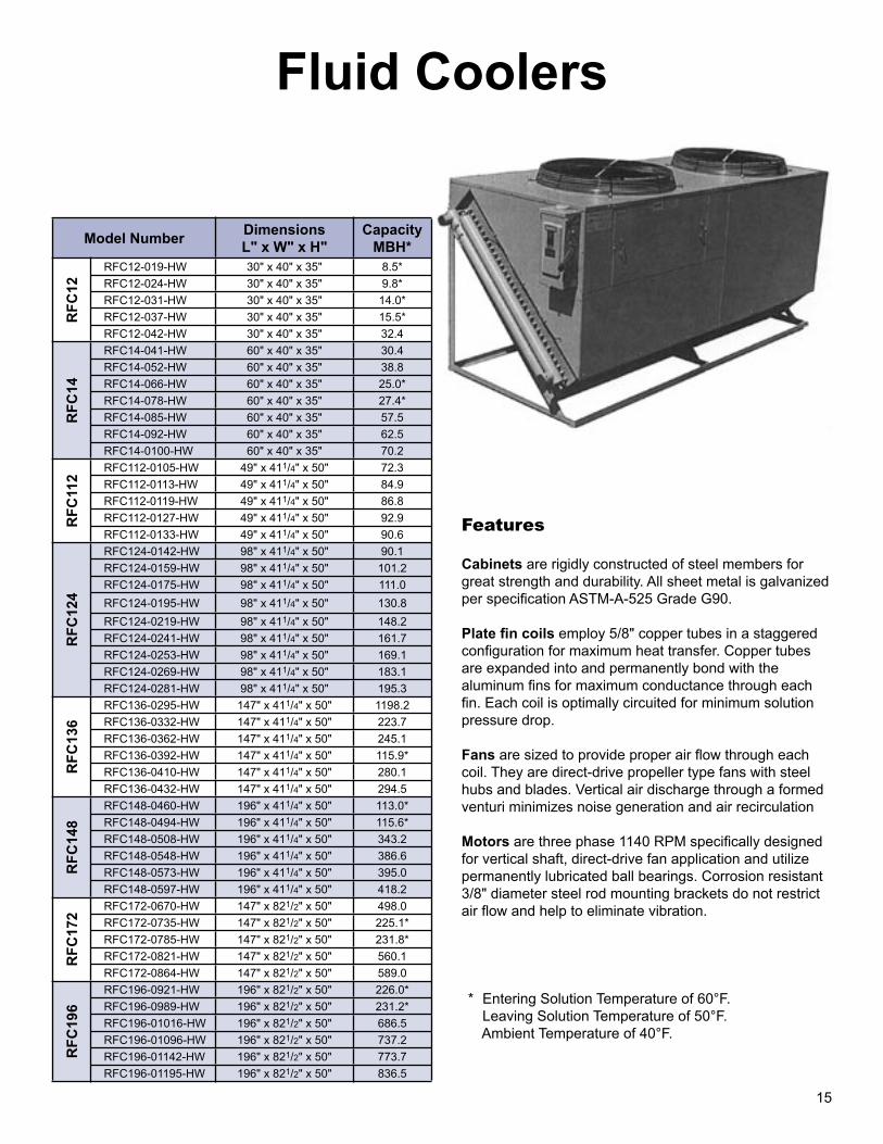
10
Booster CoilsModel Number Nomenclature 58B 12 X 12 -10 - 1 - W E R - A5/8" O.D. TubingBooster Coil, B = Duct Flanges, BS = Slip & DriveFinned Height x Finned LengthFins Per InchRows DeepWaffled Fin
Part Number
Model Number EAT LAT TOTAL BTUH* APD EWT LWT WD
100 58B 6 X 6-10-1 WER-A 55° 73.1 3,930 .16" 180 160 .07'101 58B 6 X 9-10-1 WER-A 55° 76.2 6,900 .16" 180 160 .20'102 58B 6X12-10-1 WER-A 55° 78.1 10,000 .16" 180 160 .39'103 58B 6X15-10-1 WER-A 55° 79.2 13,140 .16" 180 160 .66'104 58B 6X18-10-1 WER-A 55° 80.1 16,320 .16" 180 160 1.00'105 58B 9 X 9-10-1 WER-A 55° 78.7 11,560 .16" 180 160 .60'106 58B 9X12-10-1 WER-A 55° 80.1 16,320 .16" 180 160 1.14'107 58B 9X15-10-1 WER-A 55° 81.1 21,130 .16" 180 160 1.87'108 58B 9X18-10-1 WER-A 55° 81.6 26,000 .16" 180 160 2.82'109 58B 12X12-10-1 WER-A 55° 81.2 22,750 .16" 180 160 2.42'110 58B 12X15-10-1 WER-A 55° 82.1 29,240 .16" 180 160 3.90'111 58B 12X18-10-1 WER-A 55° 82.5 35,750 .16" 180 160 5.77'112 58B 12X24-10-1 WJR-A 55° 81.2 45,510 .16" 180 160 1.91'113 58B 12X30-10-1 WJR-A 55° 82.1 58,470 .16" 180 160 3.12'114 58B 12X36-10-1 WJR-A 55° 82.5 71,500 .16" 180 160 4.65'115 58B 15X18-10-1WJR-A 55° 81.1 42,280 .16" 180 160 1.76'116 58B 15X24-10-1WJR-A 55° 82.1 58,470 .16" 180 160 3.31'117 58B 15X30-10-1WJR-A 55° 82.6 74,770 .16" 180 160 5.39'118 58B 15X36-10-1WJR-A 55° 83.2 91,140 .16" 180 160 8.02'119 58B 18X18-10-1WQR-B 55° 80.1 78,970 .16" 180 160 1.00'120 58B 18X24-10-1WQR-B 55° 81.2 68,260 .16" 180 160 1.91'121 58B 18X30-10-1WQR-B 55° 82.1 87,710 .16" 180 160 3.12'122 58B 8 X36-10-1WQR-B 55° 82.5 107,260 .16" 180 160 4.65'123 58B 18X42-10-1WQR-B 55° 82.9 126,880 .16" 180 160 6.53'124 58B 18X48-10-1WQR-B 55° 83.2 146,550 .16" 180 160 8.76'125 58B 24X24-10-1WQR-C 55° 81.2 91,020 .16" 180 160 1.91'126 58B 24X30-10-1WQR-C 55° 82.1 116,940 .16" 180 160 3.12'127 58B 24X36-10-1WQR-C 55° 82.5 143,010 .16" 180 160 4.65'128 58B 24X48-10-1WQR-C 55° 83.2 195,400 .16" 180 160 8.76'200 58B 6 X 6-10-2WER-A 55° 95.2 8,780 .33" 180 160 .41'201 58B 6 X 9-10-2WER-A 55° 98.9 14,290 .33" 180 160 1.02'202 58B 6 X12-10-2WER-A 55° 100.8 19,880 .33" 180 160 1.90'203 58B 6 X15-10-2WER-A 55° 102.1 25,510 .33" 180 160 3.06'204 58B 6 X18-10-2WER-A 55° 102.9 31,170 .33" 180 160 4.52'205 58B 9 X 9-10-2WER-A 55° 101.5 22,680 .33" 180 160 2.94'206 58B 9 X12-10-2WER-A 55° 102.9 31,160 .33" 180 160 5.37'207 58B 9 X15-10-2WER-A 55° 103.8 39,690 .33" 180 160 8.56'208 58B 9 X18-10-2WJR-A 55° 101.5 45,380 .33" 180 160 2.20'209 58B 12X12-10-2WJR-A 55° 100.8 39,750 .33" 180 160 1.90'210 58B 12X15-10-2WJR-A 55° 102.1 51,020 .33" 180 160 3.06'211 58B 12X18-10-2WJR-A 55° 102.9 62,340 .33" 180 160 4.52'212 58B 12X24-10-2WJR-A 55° 104.1 85,080 .33" 180 160 8.34'213 58B 12X30-10-2WHR-A 55° 102.1 102,040 .33" 180 160 2.44'214 58B 12X36-10-2WHR-A 55° 102.9 124,680 .33" 180 160 3.64'215 58B 15X18-10-2WHR-B 55° 98.6 71,440 .33" 180 160 .79'216 58B 15X24-10-2WHR-B 55° 100.8 99,390 .33" 180 160 1.49'217 58B 15X30-10-2WHR-B 55° 102.1 127,550 .33" 180 160 2.44'218 58B 15X36-10-2WHR-B 55° 102.9 155,850 .33" 180 160 3.64'219 58B 18X18-10-2WQR-C 55° 102.9 93,510 .33" 180 160 4.52'220 58B 18X24-10-2WQR-C 55° 104.1 127,620 .33" 180 160 8.34'221 58B 18X30-10-2WHR-C 55° 102.1 153,060 .33" 180 160 2.44'222 58B 18X36-10-2WHR-C 55° 102.9 187,020 .33" 180 160 3.64'223 58B 18x42-10-2WHR-C 55° 103.5 221,090 .33" 180 160 5.10'224 58B 18x48-10-2WHR-C 55° 104.1 255,240 .33" 180 160 6.84'225 58B 21X30-10-2WHR-C 55° 102.1 178,570 .33" 180 160 2.44'226 58B 21X36-10-2WHR-C 55° 102.9 218,800 .33" 180 160 3.64'227 58B 21X48-10-2WHR-C 55° 104.1 297,780 .33" 180 160 6.84'228 58B 24X24-10-2WQR-C 55° 104.1 170,160 .33" 180 160 8.34'229 58B 24X30-10-2WHR-C 55° 102.1 204,080 .33" 180 160 2.44'230 58B 24X36-10-2WHR-C 55° 102.9 249,350 .33" 180 160 3.64'231 58B 24X48-10-2WHR-C 55° 104.1 340,320 .33" 180 160 6.84'
NOTES:Information is for 180°F EWT. In models with 1 row (100s): For 200° EWT, add 5.5° to LAT. For 160° EWT, subtract 5.5° from LAT.
In models with 2 rows (200s): For 200° EWT, add 9.5° to LAT. For 160° EWT, subtract 9.5° from LAT.
* Capacity is based on entering air temperature of 55° and an entering water temperature of 180° with a face velocity of 800 FPM.
Due to this being a stocking product line, there will be no exceptions to sizes or any changes allowed.
Connection Size A = 3/4" MPT B = 1" MPT C = 1 1/4" MPT
Right HandCircuiting E = 1 Tube Feed H = Half J = 2 Tube Feed Q = Quarter
Coil Construction• 5/8” O.D. Smooth Wall Copper Tubing • .020” Tube Wall Thickness• .008” Corrugated Aluminum Plate Fin• 16 Gauge Galvanized Steel Casing• Duct Flanges
15
Fluid Coolers
Features
Cabinets are rigidly constructed of steel members for great strength and durability. All sheet metal is galvanized per specification ASTM-A-525 Grade G90.
Plate fin coils employ 5/8" copper tubes in a staggered configuration for maximum heat transfer. Copper tubes are expanded into and permanently bond with the aluminum fins for maximum conductance through each fin. Each coil is optimally circuited for minimum solution pressure drop.
Fans are sized to provide proper air flow through each coil. They are direct-drive propeller type fans with steel hubs and blades. Vertical air discharge through a formed venturi minimizes noise generation and air recirculation
Motors are three phase 1140 RPM specifically designed for vertical shaft, direct-drive fan application and utilize permanently lubricated ball bearings. Corrosion resistant 3/8" diameter steel rod mounting brackets do not restrict air flow and help to eliminate vibration.
Model NumberDimensionsL" x W" x H"
CapacityMBH*
RF
C12
RFC12-019-HW 30" x 40" x 35" 8.5*
RFC12-024-HW 30" x 40" x 35" 9.8*
RFC12-031-HW 30" x 40" x 35" 14.0*
RFC12-037-HW 30" x 40" x 35" 15.5*
RFC12-042-HW 30" x 40" x 35" 32.4
RF
C14
RFC14-041-HW 60" x 40" x 35" 30.4
RFC14-052-HW 60" x 40" x 35" 38.8
RFC14-066-HW 60" x 40" x 35" 25.0*
RFC14-078-HW 60" x 40" x 35" 27.4*
RFC14-085-HW 60" x 40" x 35" 57.5
RFC14-092-HW 60" x 40" x 35" 62.5
RFC14-0100-HW 60" x 40" x 35" 70.2
RF
C11
2
RFC112-0105-HW 49" x 411/4" x 50" 72.3
RFC112-0113-HW 49" x 411/4" x 50" 84.9
RFC112-0119-HW 49" x 411/4" x 50" 86.8
RFC112-0127-HW 49" x 411/4" x 50" 92.9
RFC112-0133-HW 49" x 411/4" x 50" 90.6
RF
C12
4
RFC124-0142-HW 98" x 411/4" x 50" 90.1
RFC124-0159-HW 98" x 411/4" x 50" 101.2
RFC124-0175-HW 98" x 411/4" x 50" 111.0
RFC124-0195-HW 98" x 411/4" x 50" 130.8
RFC124-0219-HW 98" x 411/4" x 50" 148.2
RFC124-0241-HW 98" x 411/4" x 50" 161.7
RFC124-0253-HW 98" x 411/4" x 50" 169.1
RFC124-0269-HW 98" x 411/4" x 50" 183.1
RFC124-0281-HW 98" x 411/4" x 50" 195.3
RF
C13
6
RFC136-0295-HW 147" x 411/4" x 50" 1198.2
RFC136-0332-HW 147" x 411/4" x 50" 223.7
RFC136-0362-HW 147" x 411/4" x 50" 245.1
RFC136-0392-HW 147" x 411/4" x 50" 115.9*
RFC136-0410-HW 147" x 411/4" x 50" 280.1
RFC136-0432-HW 147" x 411/4" x 50" 294.5
RF
C14
8
RFC148-0460-HW 196" x 411/4" x 50" 113.0*
RFC148-0494-HW 196" x 411/4" x 50" 115.6*
RFC148-0508-HW 196" x 411/4" x 50" 343.2
RFC148-0548-HW 196" x 411/4" x 50" 386.6
RFC148-0573-HW 196" x 411/4" x 50" 395.0
RFC148-0597-HW 196" x 411/4" x 50" 418.2
RF
C17
2
RFC172-0670-HW 147" x 821/2" x 50" 498.0
RFC172-0735-HW 147" x 821/2" x 50" 225.1*
RFC172-0785-HW 147" x 821/2" x 50" 231.8*
RFC172-0821-HW 147" x 821/2" x 50" 560.1
RFC172-0864-HW 147" x 821/2" x 50" 589.0
RF
C19
6
RFC196-0921-HW 196" x 821/2" x 50" 226.0*
RFC196-0989-HW 196" x 821/2" x 50" 231.2*
RFC196-01016-HW 196" x 821/2" x 50" 686.5
RFC196-01096-HW 196" x 821/2" x 50" 737.2
RFC196-01142-HW 196" x 821/2" x 50" 773.7
RFC196-01195-HW 196" x 821/2" x 50" 836.5
* Entering Solution Temperature of 60°F. Leaving Solution Temperature of 50°F. Ambient Temperature of 40°F.

Whether standard or custom engineered, Refrigeration Systems' heat transfer coils offer the optimum in efficiency, long life, and quality design. Refrigeration Systems' coils are manufactured in our facility and we take pride in putting our label on the finished product. Our experience, engineering, and commitment to excellence make Refrigeration Systems a leading supplier of heat transfer coils for all your HVAC needs. Each component of a Refrigeration Systems' coil is selected and engineered to provide the best and most versatile coil possible.
Series 12Tubes:1/2" O.D. X .017" copper tube wall thickness is standard. Tube wall thickness may be optionally provided as .025", and .032".
Fins:Die-formed tempered aluminum, copper, or acrylic coated fins with extruded fin collars provide maximum heat transfer and accurate fin spacing. Utilizing a 1.25" equilateral triangle design in a staggered pattern, the fins are available with corrugated or flat surfaces of .006", .008", and .010" thickness.
Series 58Tubes:5/8" O.D. X .020" copper tube wall thickness is standard. Tube wall thickness may be optionally provided as .025", .035", and .049".
Fins:Die-formed tempered aluminum, copper, or acrylic coated fins with extruded fin collars provide maximum heat transfer and accurate fin spacing. Utilizing a 1.5" equilateral triangle design in a staggered pattern, the fins are available with corrugated or flat surfaces of .006", .008", and .010" thickness.
Series 11 Tubes:1" O.D. X .035" aluminum tube wall thickness is standard. Copper tube wall thickness may be optionally provided as a .049".
Fins:Fins are constructed from .010" aluminum die-formed plate with a rippled-corrugated surface.
Our water coils are applicable to virtually any type of hot water, chilled water, or glycol system whether standard or custom engineered and offer the optimum in efficiency, long life, and quality design. Refrigeration Systems' ARI certified coil catalog and computer selection program allow for easy selection of hot water and chilled water coils. Our programs assist you in selecting the most economically feasible coil and provides you with information on fin spacing, row selection, and complete engineering schedule data.
Our engineering staff has extensive experience in the proper application of DX coils in air conditioning systems. Our fin spacing range of 4 FPI to 14 FPI allows us an opportunity to apply low temperature coils that may freeze condensate on the coil surface or high temperature process coils. Additionally, we can provide mounted expansion valves, sideport hot gas connectors, or integrally mounted electric heaters for defrost applications.
Refrigeration Systems manufactures standard steam and steam distributing coils. Coils may be provided with same end or opposite end connections. Coils are pitched in the case to allow for proper condensate drainage.
Condenser coils are available with single and or multiple circuits for any condensing or high particulate areas. Condenser coils may incorporate special or unique circuiting to exactly match the coil it is replacing. Integral or separate subcooling coils may be designed into the coil.
Refrigeration Systems designs and engineers our coils for corrosive atmospheres, unique configurations, and special component packages. Refrigeration Systems is an applications-oriented manufacturer of coils. Our engineering group prides itself on being able to understand your application, then translate that understanding into a design that will satisfy
your needs.9
Custom Coil Products
16
Product Coolers
Data required to calculate expanded ratings:
1. Total Required Capacity (BTUH)
2. Design Room Temperature (°F DB / °F WB)
3. Design Room Humidity (% RH)
4. Operating Temperature Difference (Temperature difference between room design and saturated suction temperature.)
Model
DimensionsL" x W" x H"
CFM
Capacity (BTUH) / °F TD*
Wet SurfaceCapacity (BTUH) / °F TD**
Dry Surface
RPCH RPCV 4 ROW 6 ROW 8 ROW 4 ROW 6 ROW 8 ROW
RPCH/RPCV-80 511/2" x 471/8" x 343/4" 511/2" x 413/4" x 681/2" 4,400 2,373 3,134 3,668 2,431 3,213 3,737
RPCH/RPCV-120 61" x 531/8" x 403/4" 61" x 473/4" x 801/2" 6,600 3,564 4,716 5,502 3,658 4,832 5,605
RPCH/RPCV-160 90" x 471/8" x 343/4" 90" x 413/4" x 681/2" 8.800 4,755 6,288 7,325 4,874 6,438 7,474
RPCH/RPCV-218 100" x 531/8" x 403/4" 100" x 473/4" x 801/2" 11,990 6,469 8,556 9,986 6,632 8,771 10,187
RPCH/RPCV-375 133" x 601/8" x 493/4" 133" x 543/4" x 961/2" 20,625 11,130 14,718 17,172 11,423 15,090 17,517
RPCH/RPCV-447 147" x 645/8" x 523/4" 147" x 591/4" x 104" 24,585 13,261 17,545 20,458 13,606 17,981 20,873
* Based on 550 FPM coil face velocity.** Based on 700 FPM coil face velocity.
5. Maximum Fins Per Inch
6. Maximum Face Velocity (For wet applications, limit coil face velocity to 550 FPM.)
7. External Static Pressure (Inch / WG)
Applications• Product Storage (above 32°F)• Processing Rooms• Ripening Rooms• Bulk / Palletized Storages
Sizes• Six Sizes 1,710 - 20,630 BTU/˚FTD 3,200 - 31,290 CFM• Direct Expansion & Glycol Coils• Air Defrost• Halocarbon Refrigerants
ConstructionModels 80 and 120 are single fan design mounted on solid tempered steel shaft. Outboard bearings are flange type, with lubrication fittings. Fan shafts are coated with a rust resistant sealer after assembly.
Models 160 through 447 are dual fan design mounted on advance technology tubular shafts. Outboard bearing design eliminates alignment problems associated with multiple inboard bearings that require center bearing structural members which hinder air flow patterns.
RPCH = Horizontal Product Cooler
RPCV = Vertical Product Cooler
Units are designed for floor and/or suspended platform mounting, and should be located within the conditioned space.

Evaporative Condenser Chillers
8
Model Number
Length Width Height LWT78°F WB
Power Source - One Power Source - Two
MCA MAX FUSE MCA MAX FUSE
Tons*KW/
Ton** 208v 230v 460v 208v 230v 460v 208v 230v 460v 208v 230v 460v
RECH-SS60 120" 96" 102" 44° 69.9 0.934 282 279.0 136.4 450 450 110 – – – – – –
RECH-SD80 122" 96" 102" 44° 93.5 0.874 330 327.7 158.2 450 450 200 – – – – – –
RECH-SD120 162" 96" 102" 44° 137.7 0.914 291.2 287.8 239.8 450 450 220 253.8 253.8 123.8 450 450 200
RECH-SD150 175" 96" 109" 44° 174.0 0.887 371.6 336.4 236.5 600 500 400 318.8 288.4 212.5 500 500 350
RECH-SD200 248" 96" 102" 44° 197.7 0.867 390.8 353.0 241.5 600 600 400 390.8 353.0 241.5 600 600 400
RECH-SM200 248" 96" 102" 44° 220.8 0.927 402.3 350.0 193.1 500 500 250 402.3 350.0 193.1 500 500 250
RECH-SM240 248" 96" 102" 44° 270.4 0.967 492.2 489.0 238.9 600 600 300 492.2 489.0 238.9 600 600 300
RECH-SM300 328" 96" 109" 44° 343.8 0.900 611.2 553.0 399.5 800 700 500 611.2 553.0 399.5 800 700 500
Unit Configuration• Single Piece Construction• Base Rail Configuration• Multiple Rigging Points• Removable Access Panels• Hinged Control Panel Access• Closed Cell Polyvinyl
Evaporator Insulation• Evaporator Heater Cable with Ambient Stat• Insulated Suction Lines• ETL Certified Unit
Refrigerant Circuit• Liquid Line Shut Off Valve
with Charging Port• Liquid Line Drier
(Replaceable Core)• Liquid Line Sight Glass /
Moisture Indicator• “MOP” Type” Thermostatic
Expansion Valve• High Pressure Safety Control• Low Pressure Operating
Control• Freeze / Low Charge Control
with Time Delay Circuit• Refrigerant Operating Charge
Evaporative Condenser• Three Phase TEFC Motors
with Permanently Lubricated Ball Bearings
• Fan Motor Contactor • Non-Clog Water Diffusers• PVC Eliminators
Electrical Components• Return Water Temperature Control• Fused Control Circuit• Prewired Controls• Flow Switch for Field
Installation• Auto / Demand Pumpdown Switch• UL 508 Certified• Phase Failure Protection
Compressors• Semi-Hermatic Screw Compressors• Compressor Service Valves• Compressor Overload Protection• Compressor Fusing • Compressor Contactors• Compressor Time Delay• Compressor Isolator Pads• Oil Equalization System Each Circuit
(CM units)
* Based on ARI Standard 590-92.** KW is based on total unit power.
17
Pump Packages
Model Number
Pump Quantity
Flow RangeDimensions L" x W" x H"
OperatingWeight
50' Total System Head*
100' Total System Head*
Motor Horsepower
Pump Speed RPM
Motor Horsepower
Pump Speed RPM
RPS-20 1 1-20 GPM 48" x 36" x 48" 840 lbs. 1 1750 — —
RPS-45 1 21-45 GPM 48" x 36" x 48" 1,140 lbs. 2 1750 5 1750
RPS-80 1 46-80 GPM 60" x 36" x 48" 1,425 lbs. 3 1750 5 3500
RPS-130 1 81-130 GPM 72" x 36" x 60" 1,620 lbs. 5 1750 7.5 3500
RPS-200 1 131-200 GPM 72" x 48" x 66" 2,040 lbs. 5 3500 10 3500
RPS-350 1 201-350 GPM 84" x 48" x 66" 2,660 lbs. 7.5 3500 15 3500
RPS-600 1 351-600 GPM 96" x 60" x 72" 3,410 lbs. 10 3500 20 3500
RPS-800 1 601-800 GPM 96" x 84" x 72" 4,760 lbs. 15 3500 25 3500
RPD-20 2 1-20 GPM 48" x 42" x 48" 1,330 lbs. 1 1750 — —
RPD-45 2 21-45 GPM 48" x 42" x 48" 1,470 lbs. 2 1750 5 1750
RPD-80 2 46-80 GPM 60" x 48" x 48" 1,650 lbs. 3 1750 5 3500
RPD-130 2 81-130 GPM 72" x 60" x 60" 1,955 lbs. 5 1750 7.5 3500
RPD-200 2 131-200 GPM 72" x 60" x 66" 2,285 lbs. 5 3500 10 3500
RPD-350 2 201-350 GPM 84" x 60" x 66" 3,010 lbs. 7.5 3500 15 3500
RPD-600 2 351-600 GPM 96" x 84" x 72" 5,040 lbs. 10 3500 20 3500
RPD-800 2 601-800 GPM 96" x 84" x 72" 5,880 lbs. 15 3500 25 3500
* Total head includes a 15' internal drop for pump package.
Standard Features• Close-coupled, end-suction, centrifugal pumps• Mounted and wired pump starters• Hand-Off-Auto switch for each pump• Pump selector switch on dual pump packages only• Mounted and wired paddle-type flow switch• Isolation valve on suction side of pump
(ball-type valve through 2 1/2” pipe size, butterfly-type valve 3” pipe size and up)
• Strainer installed on suction side of pump (wye strainer through 3”, basket strainer 4” and up)
• Vertical scale Fahrenheit thermometers• Dial-type differential pressure gauge with shutoff
valves across the pump• Dielectric unions at each dissimilar metal connection• 1/2” closed cell insulation on all piping and
components• Structural steel base rail configuration• Corrosion resistant epoxy coating• NEMA 3R hinged door control panel with UL 508 label• Automatic switchover to standby pump based on flow
or overload failure (dual pump packages only)

7
Water Cooled Chillers
Standard Features• Narrow Profile• Structural Supports• Hinged Control Panel Access• Painted Enamel Unit• Liquid Line Shut Off Valve with Charging Port• Oil Failure Switch/Each Compressor
(CS, CD & CM Series)• High Pressure Safety Control• Low Pressure Operating Control• Refrigerant Operating Charge• Fused Control Circuit• Prewired Controls• Auto/Demand Pumpdown Switch• Flow Switch (Shipped Loose)• Manual Lead/Lag Switch (LD, CD, CM Series)• Freeze Stat - Pressure Sensing
Low Pressure Safety• Compressor Service Valves• Energy Efficient Copeland Compressors• Internal Compressor Overload Protection (All 3
Windings)• Compressor Fusing (LD, CD & CM Series)• Crankcase Heaters• Compressor Contactors• Time Delay Compressor Start (LD, CD & CM Series)• Compressor Isolator Pads• Oil Equalization system For Each Circuit (CM Series)• MOP Expansion Valves• NEMA 3 UL 508 Labeled Electrical Panel• Microelectronic Return Water Temperature Control• Replaceable Core Driers (CM Series Only)
Model NumberDimensionsL" x W" x H"
Leaving Water
Temperature
85° Ambient
TONS EER**
RWCH-LS 3 60" x 35" x 27" 44° 2.91 19.16RWCH-LS 5 60" x 35" x 27" 44° 4.99 16.86RWCH-LS 8 60" x 35" x 27" 44° 7.38 16.78RWCH-LS 9 60" x 35" x 27" 44° 8.63 15.87
RWCH-LS 10 60" x 35" x 27" 44° 9.67 15.30RWCH-LS 13 60" x 35" x 27" 44° 12.17 15.36RWCH-LS 15 60" x 35" x 27" 44° 14.46 14.81
RWCH-LD 10 70" x 35" x 36" 44° 10.09 17.27RWCH-LD 15 70" x 35" x 36" 44° 14.56 16.70RWCH-LD 18 70" x 35" x 36" 44° 17.26 15.87RWCH-LD 20 70" x 35" x 36" 44° 20.18 15.75RWCH-LD 26 70" x 35" x 36" 44° 24.86 15.61RWCH-LD 30 70" x 35" x 36" 44° 28.50 14.66
RWCH-CS 5 59" x 35" x 421/2" 44° 6.24 18.57RWCH-CS 8 59" x 35" x 421/2" 44° 8.42 16.45
RWCH-CS 10 621/2" x 35" x 421/2" 44° 11.65 15.01RWCH-CS 15 621/2" x 35" x 441/2" 44° 15.29 14.16RWCH-CS 20 66" x 35" x 441/2" 44° 17.68 16.49RWCH-CS 25 66" x 35" x 441/2" 44° 22.26 15.72RWCH-CS 30 66" x 35" x 441/2" 44° 25.58 14.28RWCH-CS 35 91" x 35" x 57" 44° 34.11 14.31RWCH-CS 40 91" x 35" x 57" 44° 40.14 15.39RWCH-CS 50 91" x 35" x 57" 44° 45.86 13.88RWCH-CS 60 91" x 35" x 57" 44° 53.35 12.95
RWCH-CD 10 76" x 35" x 63" 44° 11.54 15.52RWCH-CD 15 70" x 35" x 65" 44° 16.85 16.58RWCH-CD 20 80" x 35" x 65" 44° 23.82 15327RWCH-CD 30 80" x 35" x 67" 44° 30.06 14.02RWCH-CD 40 106" x 35" x 72" 44° 37.34 17.10RWCH-CD 45 106" x 35" x 72" 44° 41.18 16.08RWCH-CD 50 106" x 35" x 82" 44° 45.66 15.99RWCH-CD 55 106" x 35" x 82" 44° 49.82 15.38RWCH-CD 60 106" x 35" x 82" 44° 53.04 14.67RWCH-CD 65 106" x 35" x 84" 44° 60.11 14.73RWCH-CD 70 106" x 35" x 84" 44° 66.04 14.04RWCH-CD 75 106" x 35" x 84" 44° 70.31 14.00RWCH-CD 80 106" x 35" x 84" 44° 76.86 14.99RWCH-CD 90 106" x 40" x 88" 44° 83.20 14.25
RWCH-CD 100 106" x 40" x 91" 44° 91.21 13.82RWCH-CD 110 106" x 40" x 91" 44° 99.22 13.57RWCH-CD 120 106" x 40" x 91" 44° 105.46 12.85
RWCH-CM 90 142" x 35" x 89" 44° 82.27 14.92RWCH-CM 100 142" x 35" x 89" 44° 89.23 15.05RWCH-CM 110 142" x 35" x 89" 44° 97.03 15.07RWCH-CM 120 142" x 42" x 89" 44° 102.86 14.33RWCH-CM 130 142" x 42" x 91" 44° 119.70 14.53RWCH-CM 140 142" x 42" x 91" 44° 129.90 13.64RWCH-CM 150 142" x 42" x 91" 44° 140.40 14.21RWCH-CM 160 142" x 42" x 91" 44° 148.72 14.20RWCH-CM 180 154" x 42" x 89" 44° 161.0 13.2RWCH-CM 200 154" x 42" x 89" 44° 175.0 13.2RWCH-CM 220 154" x 42" x 89" 44° 192.1 12.6RWCH-CM 240 154" x 42" x 89" 44° 207.0 12.2
18
Medium Profile Unit Coolers
* All units are 26" deep and 30 15/16" tall. ** Capacity based on R-22.
AIR DEFROST ELECTRIC DEFROSTModel
Number Width* CFMCapacity** Model
Number Width* CFMCapacity**
+25° SST +45° SST -40° SST 0° SST +25° SST
5 F
PI
RFCA-150YA-140 46" 3,270 17,934 20,087
4 F
PI
RFCA-140YE-126 46" 3,310 10,332 13,860 15,372
RFCA-150YA-153 46" 3,930 19,600 N/A RFCA-140YE-137 46" 4,030 11,234 15,070 16,715
RFCA-150YA-185 46" 3,170 23,699 26,542 RFCA-140YE-169 46" 3,220 13,520 18,590 20,618
RFCA-150YA-206 46" 3,784 26,389 29,555 RFCA-140YE-185 46" 3,810 15,170 20,350 22,570
RFCA-250YA-281 76" 6,540 35,996 40,316 RFCA-240YE-253 76" 6,630 20,746 27,830 30,866
RFCA-250YA-307 76" 7,860 39,327 N/A RFCA-240YE-275 76" 8,060 22,500 30,250 33,550
RFCA-250YA-371 76" 6,340 47,525 53,228 RFCA-240YE-338 76" 6,440 27,716 37,180 41,236
RFCA-250YA-413 76" 7,568 52,905 57,154 RFCA-240YE-371 76" 7,620 30,422 40,810 45,262
RFCA-350YA-422 106" 9,810 54,071 60,560 RFCA-340YE-379 106" 9,940 31,078 41,690 46,238
RFCA-350YA-461 106" 11,790 59,054 N/A RFCA-340YE-413 106" 12,090 33,866 45,430 50,386
RFCA-350YA-556 106" 9,510 71,288 79,842 RFCA-340YE-507 106" 9,750 41,574 55,770 61,854
RFCA-350YA-620 106" 11,352 79,422 88,,953 RFCA-340YE-556 106" 11,430 45,592 61,160 67,832
RFCA-450YA-745 136" 12,680 95,499 106,958 RFCA-440YE-679 136" 12,970 55,678 74,690 82,838
RFCA-450YA-830 136" 15,208 106,323 119,082 RFCA-440YE-745 136" 15,240 61,090 81,950 90,890
RFCA-450YA-925 136" 15,920 118,493 132,712 RFCA-440YE-841 136" 16,120 68,962 92,510 102,602
6 F
PI
RFCA-160YA-150 46" 3,260 19,764 22,135
5 F
PI
RFCA-150YE-140 46" 3,270 12,054 16,170 17,934
RFCA-160YA-164 46" 3,880 21,608 N/A RFCA-150YE-153 46" 3,930 13,173 17,672 19,600
RFCA-160YA-193 46" 3,050 25,430 28,482 RFCA-150YE-185 46" 3,170 15,929 21,368 23,699
RFCA-160YA-212 46" 3,760 27,933 31,285 RFCA-150YE-206 46" 3,784 17,737 23,793 26,389
RFCA-260YA-301 76" 6,520 39,660 44,419 RFCA-250YE-281 76" 6,540 24,194 32,456 35,996
RFCA-260YA-328 76" 7,760 43,217 N/A RFCA-250YE-307 76" 7,860 26,433 35,459 39,327
RFCA-260YA-387 76" 6,100 50,991 57,110 RFCA-250YE-371 76" 6,340 31,943 42,851 47,525
RFCA-260YA-424 76" 7,520 55,869 62,570 RFCA-250YE-413 76" 7,568 35,559 47,702 52,905
RFCA-360YA-451 106" 9,780 59,424 66,555 RFCA-350YE-422 106" 9,810 36,343 48,753 54,071
RFCA-360YA-492 106" 11,640 64,826 N/A RFCA-350YE-461 106" 11,790 36,692 53,246 59,054
RFCA-360YA-581 106" 9,150 76,553 85,739 RFCA-350YE-556 106" 9,510 47,915 64,276 71,288
RFCA-360YA-636 106" 11,280 83,799 93,855 RFCA-350YE-620 106" 11,352 53,382 71,610 79,422
RFCA-460YA-779 136" 12,200 102,641 114,958 RFCA-450YE-745 136" 12,680 64,188 86,105 95,499
RFCA-460YA-852 136" 15,040 112,260 125,730 RFCA-450YE-830 136" 15,208 71,463 95,865 106,323
RFCA-460YA-978 136" 15,536 128,861 144,324 RFCA-450YE-925 136" 15,920 79,643 106,838 118,493
8 F
PI
RFCA-180YA-165 46" 3,160 22,143 24,800
6 F
PI
RFCA-160YE-150 46" 3,260
Not rated for use in this range.
17,820 19,754
RFCA-180YA-208 46" 2,950 27,914 31,263 RFCA-160YE-164 46" 3,880 19,483 21,609
RFCA-280YA-330 76" 6,320 44,286 49,600 RFCA-160YE-193 46" 3,050 22,928 25,430
RFCA-280YA-417 76" 5,900 55,961 62,678 RFCA-160YE-212 46" 3,760 25,186 27,933
RFCA-380YA-495 106" 9,480 66,429 74,401 RFCA-260YE-301 76" 6,520 35,759 39,660
RFCA-380YA-626 106" 8,850 84,009 94,091 RFCA-260YE-328 76" 7,760 38,966 43,217
RFCA-480YA-839 136" 11,800 112,594 126,105 RFCA-260YE-387 76" 6,100 45,976 50,992
RFCA-480YA-1050 136" 15,132 140,910 157,819 RFCA-260YE-424 76" 7,520 50,371 55,869
RFCA-360YE-451 106" 9,780 53,578 59,424
RFCA-360YE-492 106" 11,640 58,450 64,826
RFCA-360YE-581 106" 9,150 69,023 76,533
RFCA-360YE-636 106" 11,280 75,555 83,799
RFCA-460YE-779 136" 12,200 92,545 102,641
RFCA-460YE-852 136" 15,040 101,548 112,269
RFCA-460YE-978 136" 15,536 116,186 128,869
Air Defrost - Cooler applications above +35°F• 38 models available 17,934 to 160,639 BTUH • Fin spacing at 5, 6, or 8 per inch
Electric Defrost - Cooler/Freezer applications to -30°F operating room temperature
• 45 models available 10,332 to 128,869 BTUH • Fin spacing at 4, 5, or 6 per inch• 60 to 70 feet air throw• Insulated drain pan and adjustable defrost termination/fan delay is standard.

6
Air Cooled Chillers
Unit Configuration• Low Profile• Base Rail Configuration• Multiple Rigging Points• Removable Access Panels• Hinged Control Panel Access• Closed Cell Polyvinyl
Evaporator Insulation• Evaporator Heater Cable with
Ambient Stat• Insulated Suction Lines• ETL Certified Unit
Refrigerant Circuit• Liquid Line Shut Off Valve
with Charging Port• Liquid Line Drier• Liquid Line Sight Glass /
Moisture Indicator• “MOP” Type” Thermostatic
Expansion Valve• Oil Failure Switch on each
Compressor (CS, CD, & CM units)
• High Pressure Safety Control• Low Pressure Operating
Control• Freeze / Low Charge Control
with Time Delay Circuit• Refrigerant Operating Charge
Condenser• Direct Drive Condenser Fans• Epoxy Powder Coated Fan
Guards• Three Phase Motors with
Permanently Lubricated Ball Bearings
• Fan Staging Head Pressure Control to +20°F
• Sub-Circuit Fan Motor Fusing with Internal Overload Motor Protector
• Fan Motor Contactor • Plate Fin / Full Tube
Collar Condenser Coils• Baffled Condenser Plenum• “True” Subcooling
Electrical Components• Return Water Temperature
Control• Fused Control Circuit• Prewired Controls• Flow Switch for Field
Installation• Auto / Demand Pumpdown
Switch• UL 508 Certified
Compressors• Energy Efficient Copeland
Compressors• Compressor Service Valves• Internal Compressor
Overload Protection• Compressor Fusing
(LD, CD & CM units)• Compressor Contactors• Compressor Time Delay (LD,
CD, & CM units)• Compressor Isolator Pads• Oil Equalization System each
Circuit (CM units)
Model Number
DimensionsL" x W" x H"
Leaving Water Temp.
85° Ambient
TONS EER*
RCH-LS 3 76" x 34" x 46" 44° 2.81 12.22RCH-LS 5 76" x 34" x 46" 44° 4.89 12.04RCH-LS 8 87" x 34" x 46" 44° 7.07 11.41RCH-LS 9 87" x 34" x 46" 44° 8.42 12.14
RCH-LS 10 87" x 34" x 46" 44° 9.57 11.79RCH-LS 13 120" x 34" x 46" 44° 12.06 11.26RCH-LS 15 120" x 34" x 46" 44° 14.26 11.00
RCH-LD 10 76" x 68" x 53" 44° 9.67 11.92RCH-LD 15 87" x 68" x 53" 44° 13.62 11.06RCH-LD 18 87" x 68" x 53" 44° 16.33 11.83 RCH-LD 20 87" x 68" x 53" 44° 19.14 11.79RCH-LD 26 120" x 68" x 53" 44° 24.13 11.26RCH-LD 30 120" x 68" x 53" 44° 27.98 10.83
RCH-CS 5 75" x 34" x 46" 44° 5.62 12.37RCH-CS 8 87" x 34" x 46" 44° 7.90 11.43
RCH-CS 10 87" x 34" x 46" 44° 11.34 11.76RCH-CS 15 120" x 34" x 46" 44° 14.77 10.68RCH-CS 20 120" x 34" x 46" 44° 16.85 11.90RCH-CS 25 143" x 34" x 53" 44° 21.32 11.80RCH-CS 30 143" x 34" x 53" 44° 24.96 11.05RCH-CS 35 180" x 44" x 53" 44° 31.70 12.00RCH-CS 40 180" x 44" x 53" 44° 37.54 11.69RCH-CS 50 143" x 68" x 63" 44° 44.20 11.17RCH-CS 60 143" x 68" x 63" 44° 50.02 10.27
RCH-CD 10 87" x 68" x 53" 44° 11.54 13.06RCH-CD 15 87" x 68" x 53" 44° 15.39 11.26RCH-CD 20 120" x 68" x 53" 44° 23.19 12.55RCH-CD 30 143" x 68" x 63" 44° 30.06 11.43RCH-CD 40 143" x 68" x 63" 44° 34.74 12.03RCH-CD 45 143" x 68" x 63" 44° 39.73 12.42RCH-CD 50 143" x 68" x 63" 44° 43.26 11.86RCH-CD 55 143" x 68" x 63" 44° 46.70 11.68RCH-CD 60 143" x 68" x 63" 44° 50.13 11.08RCH-CD 65 143" x 68" x 63" 44° 54.30 10.70RCH-CD 70 180" x 88" x 63" 44° 61.60 11.80RCH-CD 75 180" x 88" x 63" 44° 66.50 11.40RCH-CD 80 180" x 88" x 63" 44° 72.70 11.52RCH-CD 90 180" x 88" x 63" 44° 80.18 11.15
RCH-CD 100 180" x 88" x 63" 44° 87.15 11.30RCH-CD 110 180" x 88" x 63" 44° 94.54 10.77RCH-CD 120 180" x 88" x 63" 44° 99.42 10.21
RCH-CM 90 180" x 88" x 63" 44° 79.77 10.21RCH-CM 100 180" x 88" x 63" 44° 84.34 11.68RCH-CM 110 180" x 88" x 63" 44° 92.87 11.59RCH-CM 120 180" x 88" x 63" 44° 97.97 11.07RCH-CM 122 264" x 96" x 63" 44° 104.00 12.10RCH-CM 130 264" x 96" x 63" 44° 108.20 11.60RCH-CM 140 264" x 96" x 63" 44° 122.40 11.70RCH-CM 150 264" x 96" x 63" 44° 133.80 11.70RCH-CM 160 264" x 96" x 63" 44° 144.04 11.45RCH-CM 180 264" x 96" x 63" 44° 156.21 10.99
* EER is for total unit efficiency.19
Extended Low Velocity Unit CoolersAir, Electric, or Hot Gas Defrost
• 4,000 to 20,000 CFM
• 16,000 to 152,000 BTUH
Model Number
DimensionsL" x W" x H"
FansQty.
CFMCapacity
0° SST +25° SST
4 F
PI
RFCV-140-175 561/4" x 521/2" x 231/4" 1 3,975 16,100 17,870
RFCV-140-211 561/4" x 521/2" x 231/4" 1 3,890 19,410 21,540
RFCV-240-349 961/4" x 521/2" x 231/4" 2 7,950 32,100 35,640
RFCV-240-422 961/4" x 521/2" x 231/4" 2 7,785 38,820 43,090
RFCV-340-523 1361/4" x 521/2" x 231/4" 3 11,925 48,120 53,410
RFCV-340-633 1361/4" x 521/2" x 231/4" 3 11,675 58,240 64,650
RFCV-440-698 1761/4" x 521/2" x 231/4" 4 15,900 64,220 71,280
RFCV-440-844 1761/4" x 521/2" x 231/4" 4 15,560 77,650 86,190
RFCV-540-872 2161/4" x 521/2" x 231/4" 5 19,870 80,220 89,040
RFCV-540-1055 2161/4" x 521/2" x 231/4" 5 19,460 97,060 107,740
5 F
PI
RFCV-150-197 561/4" x 521/2" x 231/4" 1 3,950 18,130 20,120
RFCV-150-236 561/4" x 521/2" x 231/4" 1 3,863 21,710 24,100
RFCV-250-393 961/4" x 521/2" x 231/4" 2 7,896 36,160 40,140
RFCV-250-472 961/4" x 521/2" x 231/4" 2 7,725 43,420 48,200
RFCV-350-590 1361/4" x 521/2" x 231/4" 3 11,844 54,280 60,250
RFCV-350-709 1361/4" x 521/2" x 231/4" 3 11,588 65,230 72,410
RFCV-450-786 1761/4" x 521/2" x 231/4" 4 15,792 72,310 80,260
RFCV-450-945 1761/4" x 521/2" x 231/4" 4 15,450 86,940 96,500
RFCV-550-983 2161/4" x 521/2" x 231/4" 5 19,740 90,440 100,400
RFCV-550-1180 2161/4" x 521/2" x 231/4" 5 19,313 108,560 120,500
6 F
PI
RFCV-160-209 561/4" x 521/2" x 231/4" 1 3,921 19,230 21,350
RFCV-160-251 561/4" x 521/2" x 231/4" 1 3,832 23,090 25,630
RFCV-260-417 961/4" x 521/2" x 231/4" 2 7,841 28,260 42,580
RFCV-260-502 961/4" x 521/2" x 231/4" 2 664 46,180 51,260
RFCV-360-626 1361/4" x 521/2" x 231/4" 3 11,762 57,590 63,920
RFCV-360-752 1361/4" x 521/2" x 231/4" 3 11,496 69,180 76,790
RFCV-460-834 1761/4" x 521/2" x 231/4" 4 15,682 76,730 85,170
RFCV-460-1003 1761/4" x 521/2" x 231/4" 4 15,328 92,280 102,430
RFCV-560-1043 2161/4" x 521/2" x 231/4" 5 19,603 95,960 106,520
RFCV-560-1254 2161/4" x 521/2" x 231/4" 5 19,160 115,370 128,060
8 F
PI
RFCV-180-229 561/4" x 521/2" x 231/4" 1 3,863
Not rated for use in this
range.
23,390
RFCV-180-266 561/4" x 521/2" x 231/4" 1 3,735 27,160
RFCV-280-457 961/4" x 521/2" x 231/4" 2 7,725 46,670
RFCV-280-532 961/4" x 521/2" x 231/4" 2 7,469 54,330
RFCV-380-636 1361/4" x 521/2" x 231/4" 3 11,588 70,050
RFCV-380-800 1361/4" x 521/2" x 231/4" 3 11,204 81,700
RFCV-480-915 1761/4" x 521/2" x 231/4" 4 15,450 93,440
RFCV-480-1056 1761/4" x 521/2" x 231/4" 4 14,938 108,760
RFCV-580-1143 2161/4" x 521/2" x 231/4" 5 19,313 116,720
RFCV-580-1331 2161/4" x 521/2" x 231/4" 5 18,673 135,920
Applications
• Meat Cutting / Prep Rooms• Holding / Packing Rooms• Florist Boxes• High Humidity - Low TD
Features
• Low Air Velocity• Two Way Air Throw• Prewired, Thermal Protected Motors• Ceiling Flush Mount Design• Hinged Drain Pan
Options
• Electric Defrost• Hot Gas Defrost• Insulated Drain Pans• Stainless Steel Hardware• Stainless Steel Drain pan• Stainless Steel Cabinet• Acrycoat or Copper Fins

5
Air Handling Units
Model Number Length"* Width"* Height"* Weight* CFM RangeNominal Capacity
Range (tons)RPAH-4 90" 38" 37.0" 1950 1,450 - 2,000 3.6 - 5.0RPAH-5 92" 46" 37.0" 2070 1,950 - 2,670 4.9 - 6.7RPAH-6 100" 50" 37.0" 2240 2,200 - 3,000 5.5 - 7.5RPAH-7 106" 60' 37.5" 2490 2,900 - 4,000 7.3 - 10.0RPAH-8 106" 64" 37.5" 2710 3,150 - 4,333 7.9 - 10.8
RPAH-10 112" 60" 46.5" 3110 3,900 - 5,333 9.8 - 13.3RPAH-11 116" 60" 49.5" 3250 4,350 - 6,000 10.9 - 15.0RPAH-12 116" 62" 52.5" 3400 4,850 - 6,667 12.1 - 16.7RPAH-15 124" 60" 61.5" 3780 5,800 - 8,000 14.5 - 20.0RPAH-18 142" 72" 61.5" 4740 7,500 - 10,000 18.8 - 25.0RPAH-22 142" 82" 61.5" 5110 8,500 - 12,000 21.3 - 30.0RPAH-24 148" 72" 75.5" 5490 9,000 - 12,500 22.5 - 31.3RPAH-28 152" 82" 75.5" 5980 11,000 - 15,000 27.5 - 37.5RPAH-32 162" 94" 78.0" 6800 12,500 - 17,500 31.3 - 43.8RPAH-38 172" 94" 90.0" 7670 15,000 - 21,000 37.5 - 52.5RPAH-44 176" 104" 90.0" 9050 17,500 - 24,000 43.8 - 60.0RPAH-50 184" 104" 102.0" 10140 20,000 - 28,000 50.0 - 70.0RPAH-58 192" 104" 114.0" 11140 24,000 - 32,000 60.0 - 80.0
Note: Air handlers include mixing box, pleated pre-filter w/frame, 6-row/10 fpi chilled water coil, FC fan with end discharge (listed in direction of air flow). Other optional components are available.
* All dimensions and weights are for standard construction. Consult factory for job specific information.
Model Number Nomenclature
R PAH - 20 - 6 - 10 - 0 - VL - H - W
R - RAEPackaged Air Handler
Coil Face AreaCoil Rows
Coil FPICompressor Rating
Coil Position
Temperature RangeMedium Used
Product Coolers and Packaged Air HandlersExample: R PAH -22 6 10 -0 VL -M W I II III IV V VI VII VIII IX
I – Basic Model R = RAE Corporation
II – Unit Type PAH = Packaged Air Handler
III – Area of Coil Face -08 to -45 = minimum 8 square feet to maximum 45 square feet
IV – Number of Coil Rows 4 = 4 rows 6 = 6 rows 8 = 8 rows
V – Density of Fins 4 to 14 = Minimum 4 fpi to maximum 14 fpi
VI – Compressor Rating -0 = No compressor
VII – Coil Position VL = Vertical, Left hand VR = Vertical, Right hand HL = Horizontal, Left hand HR = Horizontal, Right hand
VIII – Temperature Range -H = High -M = Medium -L = Low
IX – Medium Used 2 = R-22 7 = R-507 4 = R-404a O = Other 5 = R-502 W = Water
lllllll
ll
ll
ll
ll l l l l l l l l l l l l l l l
ll
ll
ll
lllllllllll
COIL BLOWER
FILTER RACK
20
Large Profile Unit CoolersAir Defrost• For cooler applications above +35°F• 24 models available 93,062 to 256,200 BTUH • Fin spacing at 4, 5, 6, or 8 per inch• 95 to 105 feet air throw
Electric Defrost• For cooler/freezer applications to -30°F operating
room temperature• 18 models available 62,550 to 226,900 BTUH • Fin spacing at 4, 5, or 6 per inch• 95 to 105 feet air throw• Insulated drain pan and adjustable defrost
termination/fan delay is standardCabinet
Cabinets are made of heavy gauge, rust-proof smooth finish aluminum housing. All hardware is corrosion resistant. Full die-formed venturies minimize noise with maximum air throw. Fan guards are heavy gauge wire basket type coated for corrosion protection.
Model Number
Width"* CFMCapacity
-40° SST 0° SST +30° SST
4 F
PI
RFCB-240-800 106” 14,600 62,550 83,908 94,587
RFCB-240-904 106” 15,800 71,832 96,630 108,624
RFCB-340-1046 136” 20,688 85,850 115,157 129,813
RFCB-340-1216 136” 22,650 99,800 133,843 150,877
RFCB-440-1395 176” 27,500 114,395 153,500 173,000
RFCB-440-1621 176” 30,200 132,922 178,400 201,100
5 F
PI
RFCB-250-889 106” 14,300 68,720 92,180 103,912
RFCB-250-997 106” 15,500 78,500 105,270 118,669
RFCB-350-1150 136” 20,100 94,300 126,500 142,600
RFCB-350-1325 136” 22,050 108,700 145,778 164,331
RFCB-450-1533 176” 26,800 125,760 168,000 190,100
RFCB-450-1767 176” 29,400 144,894 194,300 219,100
6 F
PI
RFCB-260-912 106” 13,600 N/A 94,723 106,779
RFCB-260-1067 106” 15,200 N/A 111,012 125,141
RFCB-360-1200 136” 19,350 N/A 132,000 148,800
RFCB-360-1395 136” 21,600 N/A 153,450 172,980
RFCB-460-1600 176” 25,800 N/A 176,000 198,400
RFCB-460-1860 176” 28,800 N/A 204,600 230,600
8 F
PI
RFCB-280-1006 106” 13,500 N/A N/A 116,064
RFCB-280-1145 106” 15,000 N/A N/A 134,490
RFCB-380-1280 136” 19,050 N/A N/A 158,720
RFCB-380-1550 136” 21,450 N/A N/A 192,200
RFCB-480-1707 176” 25,400 N/A N/A 211,600
RFCB-480-2067 176” 28,600 N/A N/A 256,200
CoilCoils are copper tube, full collared die-
formed aluminum plate fin and tube sheets. Tubes are mechanically expanded for maximum heat transfer. Coils are leak tested at 350 psig under water. Solder and flare type distributors have removable nozzles. Each nozzle is sized for the specified refrigerant and temperature range. All coils require external equalized expansion valve. Expansion valve is located within the cabinet. The expansion valve compartment is heated during the defrost cycle on electric defrost models.
FansFans have heavy duty steel blades and hubs,
statically and dynamically balanced for smooth operation. They are selected for maximum air throw.
MotorsMotors are permanently lubricated and
suitable for low temperature applications. Motors are heavy duty, high efficiency, full ball bearing and have internal thermal overloads. Fan motors are pre-wired to terminal blocks.
RefrigerantsAll coils are designed for use with many
refrigerants.Electric Defrost models include pre-wired
terminal blocks, low watt density heaters, housed internal to the coil for a rapid and efficient defrost. Lower coil and drain pan heater provides fast and reliable condensate drain. Standard operating control includes an adjustable defrost termination with fan delay.
MountingThe standard mounting configuration is
ceiling hung, but optional floor mounting is available.
*All units are 34" deep and 42 5/8" tall.

4
Air Cooled Condensers
ApplicationsRefrigeration Systems Air Cooled Condensers are designed for commercial and industrial outdoor applications and utilize R-22 refrigerant. They come completely piped and wired, featuring a low profile and vertical air discharge. They also utilize a unique horizontal condenser coil design and high volume condenser fans. The design is unaffected by wind direction or extreme weather conditions.
Model NumberDimensionsL" x W" x H"
BTUH/1°
RC-AC104-H2 32" x 34" x 40" 1,852
RC-AC105-H2 32" x 34" x 40" 2,334
RC-AC106-H2 32" x 34" x 40" 2,952
RC-AC108-H2 51" x 34" x 40" 3,810
RC-AC109-H2 51" x 34" x 40" 4,228
RC-AC1010-H2 51" x 34" x 40" 4,652
RC-AC1011-H2 51" x 34" x 40" 5,377
RC-AC2014-H2 861/2" x 34" x 40" 6,816
RC-AC2018-H2 861/2" x 34" x 40" 8,701
RC-AC2021-H2 110" x 34" x 40" 10,512
RC-AC3028-H2 110" x 34" x 40" 13,531
RC-AC4034-H2 861/2" x 68" x 53" 16,616
RC-AC4037-H2 861/2" x 68" x 53" 18,386
RC-AC4042-H2 110" x 68" x 63" 21,023
RC-AC4047-H2 110" x 68" x 63" 23,281
RC-AC6055-H2 110" x 68" x 63" 27,063
RC-AC6068-H2 1441/2" x 88" x 63" 33,986
RC-AC6076-H2 1441/2" x 88" x 63" 37,864
RC-AC8084-H2 180" x 88" x 63" 41,862
RC-AC8092-H2 180" x 88" x 63" 45,967
RC-AC80112-H2 264" x 98" x 63" 55,676
RC-AC120136-H2 264" x 98" x 63" 67,810
RC-AC120150-H2 264" x 98" x 63" 75,001
RC-AC160162-H2 264" x 98" x 63" 80,962
Standard FeaturesCabinetCabinets are constructed entirely of mill galvanized sheet steel panels and formed structural members. All panels are removable for access and service.
MotorsMotors are industrial duty 1140 RPM, ball bearing,
weather resistant, three-phase with inherent electrical protection.
FansFans are of heavy duty steel with a corrosion
resistant coating.
Condenser CoilsCondenser coils are of seamless copper tube with
die-stamped aluminum plate fins, galvanized steel frames and tube sheets.
21
Low Headroom Unit Coolers
Model Number*Dimension Capacity (BTUH) at 10° TD** Fans
Width"*** 0°F SST 25°F SST CFM
4 F
PI
RFCL-240-63 423/4" 6,300 6,678 1,250
RFCL-240-79 423/4" 7,900 8,374 1,230
RFCL-340-95 593/4" 9,500 10,070 1,875
RFCL-340-122 593/4" 12,200 12,932 1,845
RFCL-440-160 753/4" 16,000 16,960 2,460
RFCL-540-202 923/4" 20,200 21,412 3,075
RFCL-640-240 1083/4" 24,000 25,440 3,690
5 F
PI
RFCL-250-74 423/4" 7,400 7,844 1,220
RFCL-250-96 423/4" 9,600 10,176 1,210
RFCL-350-114 593/4" 11,400 12,084 1,830
RFCL-350-146 593/4" 14,600 15,476 1,815
RFCL-450-192 753/4" 19,200 20,352 2,420
RFCL-550-240 923/4" 24,000 25,440 3,025
RFCL-650-288 1083/4" 28,800 30,528 3,630
6 F
PI
RFCL-260-83 423/4" 8,300 8,798 1,210
RFCL-260-106 423/4" 10,600 11,236 1,20
RFCL-360-126 593/4" 12,600 13,356 1,815
RFCL-360-161 593/4" 16,100 17,066 1,800
RFCL-460-213 753/4" 21,300 22,578 2,400
RFCL-560-267 923/4" 26,700 28,302 3,000
RFCL-660-317 1083/4" 31,700 33,602 3,600
8 F
PI (
a)
RFCL-280-92 423/4" 9,200 9,752 1,200
RFCL-280-118 423/4" 11,800 12,508 1,170
RFCL-380-140 593/4" 14,000 14,840 1,800
RFCL-380-180 593/4" 18,000 19,080 1,755
RFCL-480-238 753/4" 23,800 25,228 2,340
RFCL-580-300 923/4" 30,000 31,800 2,925
RFCL-680-355 1083/4" 35,500 37,630 3,510
* All models require external equalized thermostatic expansion valve.** To determine capacities at other TDs, divide capacities shown by 10 and then multiply by the desired TD.*** All units are 15 3/4" deep and 15 7/8" tall.
Applications• Walk-in Coolers / Freezers• Beverage Boxes / Produce Storage• Air Defrost 28 selections 6,678 to 37,985 BTUH 4, 5, 6, and 8 FPI Coils• Electric Defrost 21 Selections 6,174 to 33,919 BTUH 4, 5, and 6 FPI Coils
Features• Permanently lubricated motors, low noise level fans for high, medium, and low temperature refrigeration applications• 4, 5, 6, and 8 FPI spacing for accurate matching of loads• Easy access to controls, motors, and wiring.• Ceiling flush mount design• Hinged drain pans
Options• High Efficiency PSC Motors• Electric Defrost• Hot Gas Defrost• Insulated Drain Pans• Heated Drain Pans
(a) 8 FPI coils are not recommended for applications below +35°F room temperature.

RAE Corporation was founded in 1971, as a privately-held corporation. From the beginning, the company has been dedicated to the manufacturing of compressorized equipment for the refrigeration, HVAC, and industrial markets. Our manufacturing facilities are located in the 7,000-acre Mid-America Industrial Park, 40 miles east of Tulsa, Oklahoma. The low cost utilities, excellent labor resources, and central location of this site have contributed significantly to RAE Corporation's continuing success.
RAE Corporation remains a privately-held company, but today it functions with six divisions. Each of the six divisions are involved in the HVAC and
refrigeration industry. The divisions include Century Refrigeration, Refrigeration Systems, Technical Systems, RAE Coils, Air Cube, and King Coils. Thus Refrigeration Systems has the advantages of both a dedicated sales, marketing, and engineering group and a member of a larger, more diversified parent corporation.
Our corporate structure enables us to continue our history of personal involvement with each of our customers. By focusing attention on the refrigeration market, our sales representatives and engineers are able to develop a better understanding of the customer's specific needs. At the same time, we are able to draw on the financial security
and manufacturing strength of a much larger, closely integrated corporation.
All Refrigeration Systems equipment components are UL approved. Units are ETL certified and are built to ARI standards. Applicable products are NSF certified.
Refrigeration Systems is making a world of difference. We are helping to supply consumers with the freshest food products on the planet. Meat, dairy, fruits, vegetables, and a host of other perishable products are delivered fresh to millions of homes because of our commitment to excellence and our mastery of refrigeration technology.
Refrigeration Systems
322
Low Velocity Unit Coolers
CabinetCabinets are made of heavy gauge, rust-proof
smooth finish aluminum housing. All hardware is corrosion resistant. Full die-formed venturies minimize noise with maximum air throw. Fan guards are heavy gauge wire basket type coated for corrosion protection. Units mount flush to the ceiling for ease of wash down; no difficult areas above the unit to clean.
CoilCoils are copper tube, full collared die-formed
aluminum plate fin and tube sheets. Tubes are mechanically expanded for maximum heat transfer. Coils are leak tested at 175 psig under water. Flare connection type distributors have removable nozzles. Each nozzle is sized for the specified refrigerant and temperature range. All coils require external equalized expansion valve. Expansion valve is located within the cabinet. The expansion valve compartment is heated during the defrost cycle on electric defrost models.
FansFans have heavy duty aluminum blades, statically
and dynamically balanced for smooth operation. They are selected for quiet operation and maximum air throw.
Model Number*
DimensionsL" x W" x H"
Capacity (BTUH) at 10°TD**
CFM
20°F SST 35°F SST 50°F SST
RFCV-260-50 58” 287/8” 9” 5,450 5,875 6,320 950
RFCV-260-74 58” 287/8” 101/2” 8,066 8,695 9,354 1,200
RFCV-360-100 82” 287/8” 101/2” 10,900 11,750 12,640 1,825
RFCV-360-135 82” 287/8” 12” 14,715 15,863 17,064 2,175
RFCV-460-195 102” 287/8” 12” 21,255 22,913 24,648 3,390
RFCV-460-275 102” 287/8” 15” 29,975 32,313 34,760 4,500
MotorsMotors are permanently lubricated and suitable for
low temperature applications. All motors are thermally protected, 1550 RPM.
RefrigerantsAll coils are designed for use with refrigerants R-22
and R-404a. Specify which refrigerant when ordering.
ElectricalFactory prewired to terminal blocks located on end
of unit.
DefrostStandard unit is suitable for air defrost applications
(above 32°F room). Electric defrost models (below 32°F room) are available. Removable, low watt density resistance heaters, prewired with termination and fan delay controls.
Drain PanDrain pans are hinged for ease of access and
cleaning.
* All models require external equalized thermostatic expansion valve.
** To determine capacities at other TDs, divide capacities shown by 10 and then multiply by the desired TD.

2
Refrigeration Systems
Master Catalog
Table of Contents
Air Cooled Condensers ..........................................................4
Air Handling Units...................................................................5
CHILLERS
Air Cooled Chillers ............................................................6
Water Cooled Chillers .......................................................7
Evaporative Condenser Chillers .......................................8
COILS
Custom Coil Products .......................................................9
Booster Coils...................................................................10
Slip & Drive Booster Coils ...............................................11
CONDENSING UNITS
Semi-Hermetic Compressor Condensing Units .............12
Scroll Compressor Condensing Units............................14
Fluid Coolers ........................................................................15
Product Coolers ...................................................................16
Pump Packages ...................................................................17
UNIT COOLERS
Medium Profile Unit Coolers ...........................................18
Extended Low Velocity Unit Coolers ...............................19
Large Profile Unit Coolers...............................................20
Low Headroom Unit Coolers ...........................................21
Low Velocity Unit Coolers ...............................................22
Blast Freezer Unit Coolers ..............................................23
Blast Freezer Unit CoolersUnit Coolers for blast freezer and wet cooler
applications are designed to meet the rigors of the industrial refrigeration market. Cabinets are designed with corrosion resistant G-90 mill galvanized sheet metal. Cabinet structure is designed for ceiling or stacked floor mounting. Drain pans are insulated aluminum with factory supplied drain connection.
Optimum air flow and static requirements are efficiently addressed with the 28" heavy duty, efficient airfoil cast aluminum fan blade configuration, and fan icing is kept to a minimum due to the draw-through design.
Industrial duty three-phase, permanently lubricated fan motors with ball bearings are provided in either 11/2 horsepower (1140 RPM motors) or 3 horsepower (1750 RPM motors) selections to meet the most demanding static requirements.
These unit coolers are supplied with high efficiency, custom circuited heat transfer coils. Coils are manufac-tured with copper tubes and aluminum fins. Six, eight, and ten row coils are available. Five-fin-per-inch coils are available for blast chilling applications and four-fin-per-inch coils are available for blast freezing applications.
DRY SURFACE 3 HP 1,750 RPM Fans DRY SURFACE 1.5 HP 1,140 RPM Fans WET SURFACE 1.5 HP 1,140 RPM Fans
Model Number
0" External Static
Model Number
0" External Static
Model Number
0" External Static
CFMBTUH @
-20°F SSTCFM
BTUH @ -20°F SST
CFMBTUH @ 25°F SST
1 F
an
RBF-140-52-06 11,510 51,580
1 F
an
RBF-150-45-06 9,250 45,3101
Fan
RBF-140-56-06 8,930 56,110
RBF-140-60-08 10,840 59,630 RBF-150-53-08 8,780 53,250 RBF-140-65-08 8,380 65,440
RBF-140-67-010 10,360 67,370 RBF-150-59-010 8,380 58,740 RBF-140-72-010 7,930 71,570
RBF-150-57-06 11,280 56,860 RBF-150-49-06 9,110 49,460 RBF-150-61-06 8,690 60,930
RBF-150-66-08 10,550 65,580 RBF-150-57-08 8,560 57,480 RBF-150-70-08 8,040 69,710
RBF-150-72-010 10,030 71,820 RBF-150-62-010 8,140 62,210 RBF-150-75-010 7,610 74,970
2 F
ans
RBF-240-103-06 23,030 103,150
2 F
ans
RBF-240-91-06 18,,510 90,610
2 F
ans
RBF-240-112-06 17,870 112,220
RBF-240-119-08 21,680 119,250 RBF-240-107-08 17,550 106,510 RBF-240-131-08 16,760 130,890
RBF-240-135-010 20,710 134,740 RBF-240-117-010 16,860 117,480 RBF-240-143-010 15,860 143,150
RBF-250-114-06 22,570 113,720 RBF-250-99-06 18,210 98,910 RBF-250-122-06 17,390 121,850
RBF-250-131-08 21,100 131,150 RBF-250-115-08 17,130 114,970 RBF-250-139-08 16,070 139,420
RBF-250-144-010 20,060 143,640 RBF-250-124-010 16,270 124,420 RBF-250-150-010 15,230 149,950
3 F
ans
RBF-340-145-06 33,450 144,140
3 F
ans
RBF-340-128-06 27,020 127,600
3 F
ans
RBF-340-157-06 25,820 156,670
RBF-340-166-08 30,980 166,300 RBF-340-148-08 25,140 147,970 RBF-340-181-08 23,800 181,140
RBF-340-187-010 29,430 187,330 RBF-340-163-010 23,800 163,260 RBF-340-198-010 22,350 197,910
RBF-350-158-06 32,670 157,570 RBF-350-140-06 26,330 140,060 RBF-350-169-06 24,850 168,980
RBF-350-182-08 30,090 181,730 RBF-350-160-08 24,410 159,880 RBF-350-193-08 22,680 192,800
RBF-350-198-010 28,330 198,210 RBF-350-173-010 23,300 172,860 RBF-350-207-010 21,350 207,210
4 F
ans
RBF-440-192-06 44,600 192,190
4 F
ans
RBF-440-170-06 36,020 170,220
4 F
ans
RBF-440-209-06 34,430 208,890
RBF-440-222-08 41,310 221,740 RBF-440-197-08 33,520 197,290 RBF-440-242-08 31,730 241,510
RBF-440-250-010 39,240 249,770 RBF-440-218-010 31,730 217,680 RBF-440-264-010 29,800 263,890
RBF-450-210-06 43,560 210,100 RBF-450-187-06 35,110 186,750 RBF-450-225-06 33,140 225,310
RBF-450-242-08 40,120 242,310 RBF-450-213-08 32,540 213,170 RBF-450-257-08 30,240 257,070
RBF-450-264-010 37,770 264,280 RBF-450-230-010 30,670 230,480 RBF-450-276-010 28,470 276,270
23
Dimensions: All units are 39 1/4" deep and 51 5/8" tall. Width of units: 1 fan = 61", 2 fans = 106", 3 fans = 136", 4 fan = 176".
Defrosting of the coils may be accomplished by electric defrost, air defrost, or 3 pipe hot gas defrost. The electric defrost is accomplished by chromate heaters designed specifically for the application. Heater location facilitates rapid defrost with less down time and quicker recovery. Air defrost may be used on blast chiller applications with less than 16 hours of run time per day and five-fin-per-inch coils. Hot gas defrost may be used on chiller freezer applications and is supplied with hot gas defrost drain pan.

REFRIGERATION SYSTEMS
MASTER CATALOG
P.O. Box 1206 - Pryor, OK 74362 - (918) 825-7222 - Fax (800) 264-5329
R-MC-1203
We reserve the right to change or revise specifications and product design in connection with any feature of our products. Such changes do not entitle the buyer to corresponding changes, improvements, additions, or replacement for equipment previously sold or shipped.