MAST-U RP v3 - Culham Centre for Fusion Energy · MAST Upgrade will be the first machine to include...
25
1 MAST-U_Research_Plan_v3.0 MAST Upgrade Research Plan June 2015
Transcript of MAST-U RP v3 - Culham Centre for Fusion Energy · MAST Upgrade will be the first machine to include...

1
MAST-U_Research_Plan_v3.0
MAST Upgrade Research Plan June 2015

2
MAST-U_Research_Plan_v3.0
1 INTRODUCTION AND BASIC INFORMATION ABOUT MAST UPGRADE
The MAST Upgrade programme has three main objectives that are central to the drive
towards commercial fusion power:
1. Adding to the knowledge base for ITER, the international experiment that will be the
precursor to a demonstration fusion power plant (DEMO). MAST Upgrade will help to
resolve important plasma physics questions and develop predictive models to help enhance
ITER’s performance and ensure its success.
2. Testing reactor concepts. MAST Upgrade will be the first machine to include the capability
to develop Super-X and related divertor designs, i.e. innovative plasma exhaust systems,
aspects of which if successful, could be adopted by future fusion devices, including DEMO.
MAST Upgrade will also test steady state operation with current driven by neutral beams.
3. Exploring the case for a fusion Component Test Facility (CTF). One or more CTFs would
allow crucial development and verification of fusion engineering and technology systems for
DEMO(s) (depending on the DEMO approach) and power plants. MAST Upgrade will explore
the suitability of the spherical tokamak as a candidate for a CTF – looking at current drive,
steady state behaviour, handling of high heat flux, plasma confinement, high beta operation,
and performance reliability. It will also look at the viability of the spherical tokamak as a
compact design for fusion power plants.
The main elements of the overall scope of the project are to upgrade the existing MAST
machine and associated facilities to:
• Increase the plasma pulse length and maximum current by increasing the solenoid
flux available;
• Introduce a closed pumped divertor allowing a wide range of divertor configurations,
including the ‘Super-X’ divertor, to be produced and diagnosed;
• Increase the maximum toroidal magnetic field and the maximum I2t that the toroidal
field system can sustain;
• Increase the heating power and pulse length. The neutral beam heating is planned to
be increased eventually to 10MW for 5 seconds. An ECRH system is also planned;
• Facilitate q-profile control using enhanced shaping capability (elongation and
triangularity) and off-axis neutral beams;
• Modify the vertical stabilisation system to meet the requirements of the new
configurations;
• Develop advanced shape and divertor configuration control using the 21 poloidal
field coils and the solenoid, 7 coils in each divertor
MAST is planned to be upgraded in stages, known as Core Scope, Stage 1 and Stage 2, details
of which are provided in sections 4 and 5.
Core Scope: This refers to all activities completed within the first MAST Upgrade project due
for completion in 2016. The list of system upgrades in Core Scope are discussed in section 4.

3
MAST-U_Research_Plan_v3.0
Stage 1: This refers to the addition of a third beam system to MAST Upgrade (taking the total
power to 7.5MW), a cryoplant to service the divertor cryopumps, advanced cooling of the
centrepost, a pellet injector and some additional diagnostics. Timescales for stage 1 will
depend on funding considerations.
Stage 2: This third stage of the upgrade programme will involve the addition of a fourth
beam system (taking the total power to 10MW) as well as an ECRH/EBW system.
MAST Upgrade will operate as a EUROfusion supported device within the Medium Sized
Tokamak (MST) programme, complementing two other tokamaks, namely ASDEX Upgrade
(Germany) and TCV (Switzerland). EUROfusion formulate an annual work plan for
exploitation of these devices in concerted collaboration; this period of operation will be
supplemented by UK-funded operation.
Figure 1: Cross-section of the MAST Upgrade showing the 17 new shaping and divertor coils and the
new closed divertors.
2 RESEARCH STRATEGY
The development of a fusion power plant requires substantial advances in plasma science
and technology. MAST Upgrade has been identified as one of Medium Sized Tokamaks
supported by EUROfusion funding because there are many aspects which require research

4
MAST-U_Research_Plan_v3.0
and development that are either complementary to ITER, or go beyond ITER parameters and
the spherical tokamak (ST) line may help with this research.
For example, the prototype fusion power plant, known as DEMO, will go beyond ITER
divertor heat loads with up to five times higher heating power normalised to plasma radius.
It will also require the development of technology for a much more aggressive neutron
environment, for which new components need to be tested (particularly in relation to how
their power handling and/or high temperature properties can be maintained in a high
neutron environment). It will further require the development of techniques for quasi-
continuous operation (on the scale of weeks or more, rather than hours), with fully self-
sustaining plasmas (still largely relevant even if a long pulse, e.g ~1 day, DEMO is adopted, as
there are clear attractions of a continuous fusion core for a power plant), strong current
drive, tritium breeding, and self-reconditioning, at performance levels where new
instabilities may need to be controlled from the energetic fusion products. This is
highlighted by a consideration of key parameters as set out in table 1.
The importance of the MAST Upgrade programme with respect to DEMO research is
most evident in the inclusion of a novel divertor concept. The unique open design of the
MAST Upgrade vessel is instrumental in this novel concept, which may provide a path
towards a solution to the divertor power challenge in an ST-CTF and DEMO should the
conventional approach not be acceptable. There is a strong overlap between the R&D needs
for DEMO (ITER) and the ST-CTF, many of which are more pronounced in the latter, and
MAST Upgrade research aims to address both.
Table 1 Key performance parameters /metrics for a tokamak fusion plasma: maximum parameters
achieved to date (not simultaneous), ITER goal with extended burn (and steady-state in parentheses),
DEMO based on EU Model C from D Maisonnier et al, Nucl Fusion, 47, 1524 (2007) and ST-CTF
according to G Voss et al, Fus Eng Des, 83, 1684 (2008). These CTF parameters are indicative and are
likely to evolve in future design studies, and other ST CTF/FNSF designs exist
Property Unit Metric
To Date ITER Goal DEMO ST-CTF
Major Radius R (m) 3 6.2 7.5 0.84
Plasma Volume Vp (m3) 100 840 ~1650 ~10
Magnetic Field (toroidal) Bt (T) 11 5.3 (5.2) 6.0 2.5
Plasma Current Ip (MA) 7 15 (9) 20 6.5
Fusion Power Pf (MW) 16 500 (356) 3410 35
Fusion Power Gain Q 0.6 10 (6) 30 0.9
Average Plasma Pressure <p> (MPa) 0.2 0.3 (0.24) 3 0.9
Fusion Power Density (MWm-3
) 0.16 0.6 (0.4) ~2.0 3.5
Plasma Duration (Pheat> 1MW) (s) 180 400 (3000) ∞ ∞
Self Driven Current Fraction fBS (%) 80 25 (50) 63 40
Plasma Exhaust/Pulse W (GJ) 1 60 (420) ∞ ∞
Divertor Power Challenge Pheat/R
(MW/m) ~10 ~20 ~80 ~90
Neutron Wall Loading Γn (MWm-2
) 0.1 0.5 (0.4) 2.2 1
A Component Test Facility (CTF) has been proposed to help speed the path towards
DEMO and power plants and improve their designs. The principle here is to have a facility

5
MAST-U_Research_Plan_v3.0
that allows testing, development, and validation of ideas particularly aspects of nuclear
technology (especially breeding blankets) at meaningful dimensions, so that one can make
advances and developments to complement the integrated approach of ITER and DEMO. In
particular the emphasis with a CTF is on a high neutron, high heat flux, environment in a
driven machine (ie substantially heated and controlled by external systems) in order to
understand the optimisation of device components for a power plant and the ramifications
of high heat flux and long pulse quasi-continuous operation. A major potential advantage of
an ST-based CTF is that in some designs the tritium consumption could be low enough to
avoid the necessity for self-sufficient tritium breeding, hence avoiding the reliance for
continued operation on the main components being tested, and removing the constraint
that every blanket development component needs have all the overhead and hardware for
inclusion in the tritium cycle. It is in this context that MAST Upgrade has a strong role,
alongside NSTX-U especially (the other major ST).
Research on MAST Upgrade as a EUROfusion-funded medium-sized tokamak will be
conducted using the headlines of the EUROfusion roadmap (see Appendix F). The headlines
in which MAST Upgrade will make the most significant contributions are expected to be:
o Headline 1.1: Increase the margin to achieve high fusion gain on ITER
o Headline 1.2: Operation with reduced or suppressed ELMs
o Headline 1.7: Optimise fast ion confinement and current drive
o Headline 1.9: Qualification of Advanced Tokamak scenarios
o Headline 2.1: Detachment control for the ITER and DEMO baseline strategy
o Headline 2.3: Optimise predictive models for ITER and DEMO divertor/SOL
o Headline 2.4: Investigate alternative power exhaust solutions for DEMO
With respect to burning plasma physics (headline 1.7), the addition of off-axis NBI
will allow a much larger variation of the fast particle distribution than previously possible
and the better density control with possible access to lower densities will allow access to
plasmas where the fast particle pressure dominates. The injected fast particles in MAST
Upgrade are born with velocities well above the resonant Alfvén velocity, such that the
resonance resides in the near thermalised region of the distribution and is approached from
higher energies, as would be the case in a burning plasma.
The projected performance of MAST Upgrade indicates that access to plasmas with
fully non-inductive current drive of Ip>1MA for flat top times exceeding several current
redistribution times should be possible (helping to address headlines 1.7 and 1.9). High
current fully non-inductive plasmas will only be possible using neutral beam current drive
(NBCD), most efficient in low density plasmas. However, operation at high κ, high βN and
higher density will also allow access to plasmas with a high bootstrap fraction (advanced
scenarios). Therefore, plasma control without a solenoid as well as transport and current
drive can be studied in detail. Furthermore, this can be done in an environment with high
super Alfvénic fast particle fraction, which mimics important aspects of burning plasmas.
The addition of the flexible divertor in a closed pumped volume provides a unique
capability for MAST Upgrade and will provide an integral contribution to headlines 2.1, 2.3
and notably 2.4. This key capability to explore new configurations potentially provides a
route towards a solution to the plasma exhaust problem of next generation fusion devices.
Exploring the controllability, stability and performance of the divertor as one moves from a

6
MAST-U_Research_Plan_v3.0
classic or conventional configuration to the configuration with an extended outer leg will be
pivotal for developing alternative exhaust options for DEMO/CTF. The overall flexibility of
this design will also allow studies of the general aspects of divertor physics such as SOL
cross-field transport and radiative detachment, which are crucial issues for the ST-CTF and
conventional aspect ratio power plant paths alike, whatever divertor configuration is
adopted. The long leg and closed divertor may allow greater decoupling of the divertor and
core plasma, as well as providing a flexible platform for divertor physics studies.
3 RESEARCH THEMES AND OPPORTUNITIES 2017-18
In this section, the main research themes in the present CCFE programme for the initial
operating period of MAST Upgrade are outlined (with the Core Scope hardware available,
see section 4). The programme as a whole will be developed with collaborators (who are
assumed to take leading roles), and some examples are given of areas where CCFE has fewer
staff, implying even stronger opportunities for collaborators. The part of the programme
funded by the EUROfusion MST1 work package will be organized by the MST1 Task force
leaders, and it is expected that the remaining part will be designed to complement.
Furthermore the choices for hardware enhancements will be discussed jointly with the MST1
leadership so that the MAST-U programme complements the wider EU programme. See
Appendix E for more information.
3.1 Exhaust
The closure of the divertor in MAST Upgrade is a major change from MAST and allows
closure concepts like that of the original ASDEX machine, complementing that of JET for
example. The aim is both on improving impurity and density control over MAST, and on
decoupling the effect of changes in the physical processes of the divertor from those of the
core plasma. The early experiments on MAST Upgrade will explore this fundamental precept
of the MAST Upgrade design. They will explore and quantify the effectiveness of the gas
sealing within the divertor assembly, and the extent to which the closure is limited by the
interaction of the far scrape-off layer (SOL) with the surfaces outside the divertor chambers.
The effective pumping of the
divertor chambers and their
surfaces will be a key aspect of
MAST Upgrade experiments in
general. Therefore in addition
to divertor physics studies,
early exhaust experiments and
supporting modelling work will
need to quantify and explain
this in sufficient detail to allow
for effective design of
experiments on core plasma
phenomena.
In the wider exhaust area, the Super-X divertor (SXD) and other long leg
configurations have clearly the highest impact. MAST Upgrade is the only device that will be
able to operate a closed pumped divertor in these configurations. We will aim to realise the
first Super-X divertor configuration in a closed divertor early in the 1st year of MAST-U
Figure 2 Modelling of Super-X divertor (SXD) compared to
conventional divertor (CD).

7
MAST-U_Research_Plan_v3.0
operation, with feed-forward control to demonstrate the potential of MAST-U as a flexible
exhaust physics research facility. IR cameras and Langmuir probes will be available to assess
the power load in comparison with the conventional divertor operation. Having established
operation with a long-leg divertor, also aspects of the core confinement and the effect of
SOL connection length on H-mode will be studied. In particular the effect of fuelling,
recycling and SOL flows on the L-H transition will be studied. The ability of changing the
divertor characteristics independently from the up-stream conditions will make this research
unique.
However, the flexible divertor allows access not just to the Super-X configuration, but
to a range of advanced divertor configurations. Indeed, the flexibility is such that MAST
Upgrade will be able to transition smoothly from a conventional divertor configuration to a
Super-X configuration with the strike point located at any point in between. It will also be
possible to study the so-called snowflake configuration with multiple divertor legs, as shown
in Figure 3. Furthermore, it is also possible to generate a long-legged inner divertor utilising
the closed divertor chamber with the outer strike point on the divertor nose – starting to
address options for advanced inner legs.
Figure 3: Plasma shapes achievable in MAST Upgrade, showing the core plasma is approximately the
same with either a conventional divertor configuration, a snowflake or a Super-X configuration.
The exhaust programme will also focus on volumetric loss mechanisms and parallel
and cross-field transport processes (turbulence and filaments). The first area will be aided by
divertor bolometry as well as spectroscopic measurements (e.g. 2D narrow band imaging).
This research can be done early as soon as sufficient control capability of the SXD and similar
configurations is established. Cross-field transport studies can include detailed investigations
of the changes in cross field transport with varying connection length, and their origin. This
will require higher accuracy control as well as turbulence measurements such as fast visible
imaging and reciprocating probe measurements.

8
MAST-U_Research_Plan_v3.0
Early experiments should probably focus on the underlying physics while waiting for
the additional power and pulse length capability from the later upgrades. The configurations
will be established for a few particle confinement times to achieve stationary conditions with
the core plasma.
Finally, the scaling of SXD performance to next step fusion devices requires a wide
operating space coupled with detailed divertor modelling as well as a comprehensive
diagnostic set. High current capability is needed to access low collisionality regimes. High
power is needed to access a hot sheath limited SOL at various densities. Access to other
divertor configurations such as a snowflake divertor are also possible. A detailed comparison
of open and closed divertors, as well as pumping effects can also be studied (for the first
time in a spherical tokamak).
Installed diagnostics: Divertor Langmuir probes (approx. 850 probes), midplane and
divertor reciprocating probes, divertor science facility, 2 IR cameras, 2 high-speed visible
cameras, 6 filtered imaging cameras, 1 coherence imaging system to measure impurity
flows, 32 channel gold foil divertor bolometer, 1 multi-channel grating spectrometer, 5
survey spectrometers, divertor Thomson scattering, mid-plane and divertor fast ionization
gauges.
Desirable new hardware: An additional IR camera, Improved high-speed visible cameras,
X-point imaging bolometer, divertor AXUV diodes for Lyman α/fast radiated power
measurements, improved coherence imaging to measure impurity flows and electron
density, divertor gas puff imaging, divertor reciprocating probe head to detect charge-
exchange neutrals.
3.2 Pedestal and ELMs
MAST Upgrade will be equipped, like MAST, with
excellent diagnostics for exploring the pedestal
structure and ELM dynamics, including when
resonant magnetic perturbations (RMPs) are
applied to control the ELMs. The new closed
divertor means that much lower pedestal
collisionality, relevant to ITER and DEMO
regimes, will be accessible, allowing
investigations of the pedestal structure at low
collisionality and at higher plasma current and
field. Furthermore, the new poloidal field coils
will allow the pedestal structure to be
investigated for a much wider variation in
elongation and triangularity, as well as for
variation in the divertor configuration and thus
the upstream SOL and pedestal foot conditions. The effect of impurity species on the
pedestal is a key issue for operation of ITER, and the increased flexibility in gas fuelling in
MAST Upgrade will permit studies of the effects of a variety of impurity species on the
pedestal and ELM behaviour.
Figure 4 Pedestal operating space achieved
on MAST as a function of ELM type.

9
MAST-U_Research_Plan_v3.0
MAST Upgrade will have 12 in-vessel coils (reduced from 18 in MAST), with four in
the upper row and eight in the lower row. This will allow RMPs with configurations n=1, n=2
and n=4 to be applied. There will be excellent diagnostics to assess the effect of the RMPs on
the plasma edge and ELM behaviour. Consequently, MAST Upgrade will allow an exploration
of RMP ELM control at lower collisionality with the closed divertor as well as testing the
compatibility of ELM control by RMPs (and the resultant lobe structures) with the Super-X
configuration.
Key hardware: High resolution 130-channel Thomson scattering system with sub-cm
resolution; charge exchange systems, fast imaging cameras with 120kHz frequency and
~6mm spatial resolution, BES for instabilities, long-wavelength IR thermography, in-vessel
coils for applying RMPs, synthetic aperture microwave imaging for measuring changes in
pitch angle to infer edge current profiles.
Desirable new hardware: Doppler backscattering system (the system used on MAST has
been returned to the US), Lithium beam diagnostic, pedestal turbulence diagnostics
3.3 Current drive and fast particle physics
MAST Upgrade is equipped with two neutral
beams that have different injection geometries.
One beam is injected in the equatorial plane of
the tokamak, which provides strong on-axis
deposition, while the other beam is displaced
vertically upwards to provide off-axis deposition.
Typical deposition profiles for the two beams are
illustrated using a TRANSP simulation in Figure 5.
The central deposition of the mid-plane beam is
predicted to generate non-inductive current drive
that is peaked at the plasma magnetic axis,
whereas the vertically displaced beam is expected
to produce off-axis current drive. This provides an
opportunity to investigate both current drive
physics and the effect of on- and off-axis non-inductive current on plasma behaviour.
The deposition profile for the on-axis beam is quite resilient to variations in plasma
parameters provided that the magnetic axis is close to the equatorial plane of the tokamak.
The deposition of the vertically displaced beam, on the other hand, depends on plasma
geometry and provides great flexibility. Reducing the height of the plasma or displacing it
downwards acts to move the off-axis deposition peak to larger normalised minor radius.
Figure 5 Typical MAST Upgrade beam
deposition profiles.
10
MAST-U_Research_Plan_v3.0
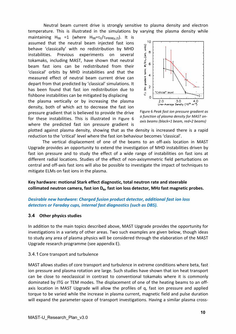
Neutral beam current drive is strongly sensitive to plasma density and electron
temperature. This is illustrated in the simulations by varying the plasma density while
maintaining H98 =1 (where H98=τE/τIPB98(y,2)). It is
assumed that the neutral beam injected fast ions
behave ‘classically’ with no redistribution by MHD
instabilities. Previous experiments on several
tokamaks, including MAST, have shown that neutral
beam fast ions can be redistributed from their
‘classical’ orbits by MHD instabilities and that the
measured effect of neutral beam current drive can
depart from that predicted by ‘classical’ simulations. It
has been found that fast ion redistribution due to
fishbone instabilities can be mitigated by displacing
the plasma vertically or by increasing the plasma
density, both of which act to decrease the fast ion
pressure gradient that is believed to provide the drive
for these instabilities. This is illustrated in Figure 6
where the predicted fast ion pressure gradient is
plotted against plasma density, showing that as the density is increased there is a rapid
reduction to the ‘critical’ level where the fast ion behaviour becomes ‘classical’.
The vertical displacement of one of the beams to an off-axis location in MAST
Upgrade provides an opportunity to extend the investigation of MHD instabilities driven by
fast ion pressure and to study the effect of a wide range of instabilities on fast ions at
different radial locations. Studies of the effect of non-axisymmetric field perturbations on
central and off-axis fast ions will also be possible to investigate the impact of techniques to
mitigate ELMs on fast ions in the plasma.
Key hardware: motional Stark effect diagnostic, total neutron rate and steerable
collimated neutron camera, fast ion Dαααα, fast ion loss detector, MHz fast magnetic probes.
Desirable new hardware: Charged fusion product detector, additional fast ion loss
detectors or Faraday cups, internal fast diagnostics (such as DBS).
3.4 Other physics studies
In addition to the main topics described above, MAST Upgrade provides the opportunity for
investigations in a variety of other areas. Two such examples are given below, though ideas
to study any area of plasma physics will be considered through the elaboration of the MAST
Upgrade research programme (see appendix E).
3.4.1 Core transport and turbulence
MAST allows studies of core transport and turbulence in extreme conditions where beta, fast
ion pressure and plasma rotation are large. Such studies have shown that ion heat transport
can be close to neoclassical in contrast to conventional tokamaks where it is commonly
dominated by ITG or TEM modes. The displacement of one of the heating beams to an off-
axis location in MAST Upgrade will allow the profiles of q, fast ion pressure and applied
torque to be varied while the increase in plasma current, magnetic field and pulse duration
will expand the parameter-space of transport investigations. Having a similar plasma cross-
Figure 6 Peak fast ion pressure gradient as
a function of plasma density for MAST on-
axis beams (black=1 beam, red=2 beams)

11
MAST-U_Research_Plan_v3.0
section to ASDEX Upgrade and DIII-D allows multi-machine studies of the effect of varying
the plasma aspect ratio. The closure of the MAST Upgrade divertor together with a range of
fuelling techniques (NBI, pellet and gas injection) also provides the potential for particle
transport investigations. Studies of the effects of fast ions on turbulence will benefit from
the fast ion fraction, super-Alfvênic particles and wide Larmor radius achievable in MAST.
STs offer a potentially attractive route to compact burning plasma devices, such as a
component test facility. However, further investigations are required to establish a robust
basis for extrapolation from present devices to the conditions required for significant fusion
gain. For example, previous studies have suggested that confinement may scale differently
with respect to plasma current and magnetic field compared with conventional tokamaks.
Indeed, the closed divertor and higher current and field will allow access to much lower
collisionality than in MAST, and the step in collisionality to an ST-based CTF is the largest in
dimensionless parameters, emphasising the need to understand this confinement scaling.
MAST Upgrade will allow such investigations to be extended as well as the study of the
influence of different divertor configurations on core plasma performance (e.g. access to H-
mode), which is at the heart of the requirement to integrate high fusion output with realistic
exhaust strategies.
Key hardware: Beam Emission Spectroscopy, FIDA, high resolution Thomson scattering,
charge exchange recombination spectroscopy, neutron camera, fast particle loss detector,
flexible system of divertor and shaping coils, in particular PC coil.
Desirable new hardware: Upgrades to the BES, Doppler back-scattering system, high-k
scattering diagnostics, high frequency pellet injector.
3.4.2 Performance limiting MHD instabilities
A key research point in MAST-U will be to avoid performance-limiting MHD instabilities, that
reduce the achievable pulse length. The high values of beta accessible on MAST and the
similarity between the typical MAST q-profile and that used in advanced scenarios (e.g.
‘hybrid’) on conventional tokamaks allows studies of various performance limiting MHD
instabilities in the domain of interest for future devices. The expansion of the plasma
operating space on MAST Upgrade in terms of q-profile, pressure profile and plasma shape
will provide the opportunity to extend these physics studies. The application of results will
be required to develop techniques for the control and avoidance of performance limiting
MHD instabilities (e.g. by q-profile tailoring) to access stationary plasma conditions. Such
work will include the study of plasma disruptions and their mitigation.
Key hardware: MSE, HRTS, Mirnov coils, SXR arrays, disruption mitigation valve, error field
correction coils.
Desirable new hardware: further diagnostics of internal structure of instabilities,
shattered pellet injection, additional disruption mitigation valves.
12
MAST-U_Research_Plan_v3.0
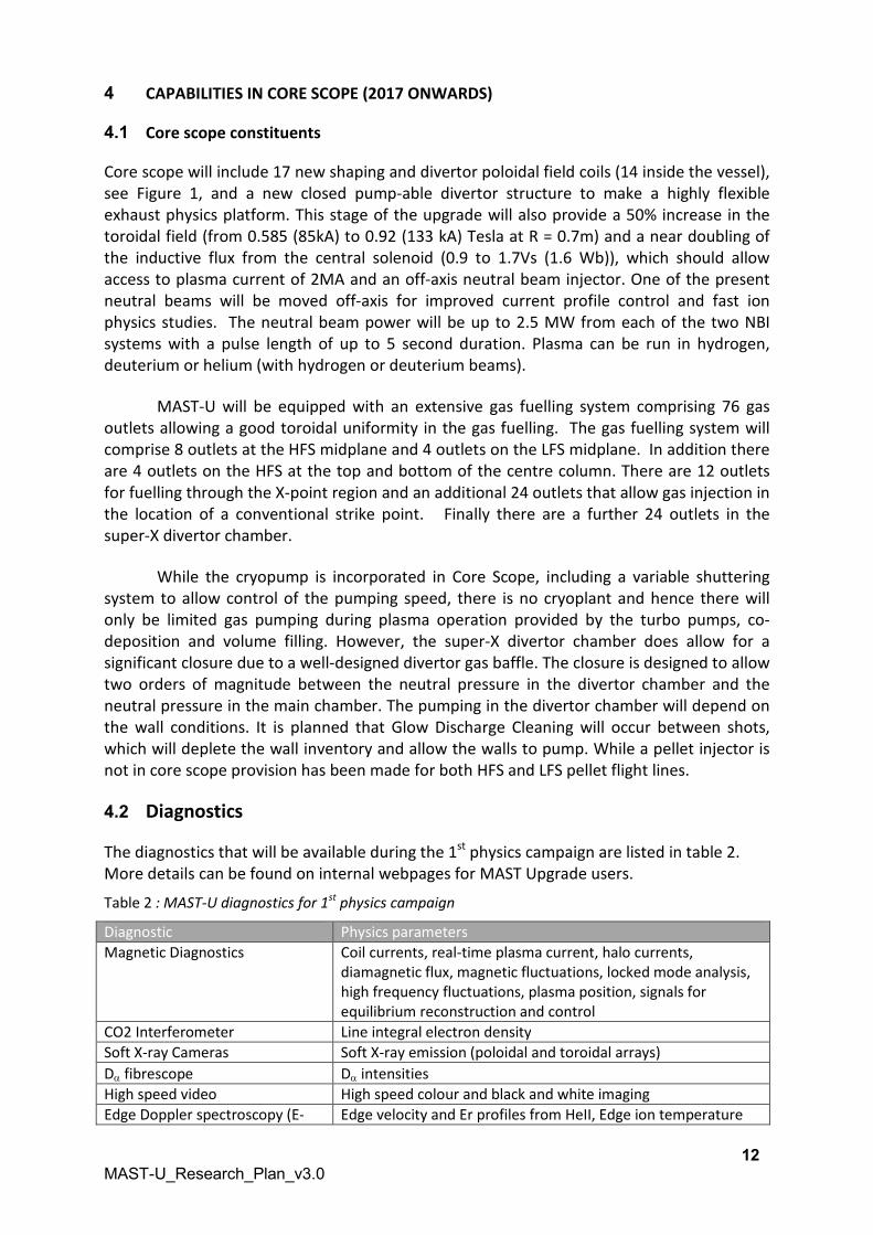
4 CAPABILITIES IN CORE SCOPE (2017 ONWARDS)
4.1 Core scope constituents
Core scope will include 17 new shaping and divertor poloidal field coils (14 inside the vessel),
see Figure 1, and a new closed pump-able divertor structure to make a highly flexible
exhaust physics platform. This stage of the upgrade will also provide a 50% increase in the
toroidal field (from 0.585 (85kA) to 0.92 (133 kA) Tesla at R = 0.7m) and a near doubling of
the inductive flux from the central solenoid (0.9 to 1.7Vs (1.6 Wb)), which should allow
access to plasma current of 2MA and an off-axis neutral beam injector. One of the present
neutral beams will be moved off-axis for improved current profile control and fast ion
physics studies. The neutral beam power will be up to 2.5 MW from each of the two NBI
systems with a pulse length of up to 5 second duration. Plasma can be run in hydrogen,
deuterium or helium (with hydrogen or deuterium beams).
MAST-U will be equipped with an extensive gas fuelling system comprising 76 gas
outlets allowing a good toroidal uniformity in the gas fuelling. The gas fuelling system will
comprise 8 outlets at the HFS midplane and 4 outlets on the LFS midplane. In addition there
are 4 outlets on the HFS at the top and bottom of the centre column. There are 12 outlets
for fuelling through the X-point region and an additional 24 outlets that allow gas injection in
the location of a conventional strike point. Finally there are a further 24 outlets in the
super-X divertor chamber.
While the cryopump is incorporated in Core Scope, including a variable shuttering
system to allow control of the pumping speed, there is no cryoplant and hence there will
only be limited gas pumping during plasma operation provided by the turbo pumps, co-
deposition and volume filling. However, the super-X divertor chamber does allow for a
significant closure due to a well-designed divertor gas baffle. The closure is designed to allow
two orders of magnitude between the neutral pressure in the divertor chamber and the
neutral pressure in the main chamber. The pumping in the divertor chamber will depend on
the wall conditions. It is planned that Glow Discharge Cleaning will occur between shots,
which will deplete the wall inventory and allow the walls to pump. While a pellet injector is
not in core scope provision has been made for both HFS and LFS pellet flight lines.
4.2 Diagnostics
The diagnostics that will be available during the 1st
physics campaign are listed in table 2.
More details can be found on internal webpages for MAST Upgrade users.
Table 2 : MAST-U diagnostics for 1st
physics campaign
Diagnostic Physics parameters
Magnetic Diagnostics Coil currents, real-time plasma current, halo currents,
diamagnetic flux, magnetic fluctuations, locked mode analysis,
high frequency fluctuations, plasma position, signals for
equilibrium reconstruction and control
CO2 Interferometer Line integral electron density
Soft X-ray Cameras Soft X-ray emission (poloidal and toroidal arrays)
Dα fibrescope Dα intensities
High speed video High speed colour and black and white imaging
Edge Doppler spectroscopy (E- Edge velocity and Er profiles from HeII, Edge ion temperature

13
MAST-U_Research_Plan_v3.0
Celeste) from CVI (CX)
Fast ion Dα (FIDA) Confined fast ion profiles
STROBE 2D South BES/Dα 100Hz
IR Cameras Medium and long wavelength IR thermography
Mid-plane and divertor
reciprocating Probe Systems –
with heads
Retarding Field Energy Analyser - Ti, Te, Jsat
Mach probe - Flow velocity, Te, Jsat
Gundestrupp probe - Plasma potential, Te, Jsat
Target Langmuir Probes Plasma potential, Te, Jsat
Fast Ion Gauge Main chamber and divertor neutral gas pressure
Hard X-ray monitors Hard X-ray emission
VUV spectroscopy (SPRED) VUV emission spectrum
Activation Samples Total neutron fluence
Beam emission spectroscopy
(BES)
2D density fluctuations (32 ch., 2 MHz)
Motional Stark effect (MSE) Magnetic pitch-angle profile
Colour imaging spectroscopy
(RGB)
2D Dα, CVI, HeI , SW BE/green/blue bremsstrahlung
Dα Linear Camera Dα intensities
Thomson Scattering (mid-plane) 130 channel Multi-time, multi-point Te(r), ne(r)
Divertor Science Facility Allows introduction of different test probe heads, dust samples
etc.
Main chamber and divertor
Bolometer systems
Measurements of Prad
Survey Spectrometer Routine survey spectra in the divertors (340-730 nm) and at the
midplane (400-750 nm)
Fission Chamber Total neutron flux
Neutron Camera Radial distribution of the neutron flux
Charge exchange recombination
spectroscopy (CXRS)
Ion temperature and velocity profiles
Zeff spectrometry (ZEBRA) 2D green bremsstrahlung: Zeff 100Hz
Divertor Camera (DIVCAM) 2D spectral line imaging
Linear camera (HOMER2) Real-time LFS plasma position
Synthetic aperture microwave
imaging (SAMI)
Magnetic pitch angle measurements in the pedestal region
Reflectometer Density profile and fluctuations
4.3 Achievable Pulse length with water-cooled centre column and 2 beams
In the first physics campaign the centre column will be cooled using water, rather than
Galden. This means that the allowable I2t in the solenoid is effectively halved from its
maximum value to 1500 kA2s, which will have implications on the maximum achievable pulse
length. While we plan to develop scenarios with low internal inductance (li) and high non-
inductive current fraction this may take some time. For the first physics campaign a good
starting point in order to calculate an expected shot duration is to use the longest shots
achieved in the final campaign on MAST (M9). Assuming these shots are run with a TF
current of 100 kA, with a ramp up/ramp down time of 500 ms, then a 1.5 s flat top has an I2t
of 18 000 kA2s well within the limit set by the sliding joints of 40 000 kA
2s (with water
otherwise 50 000 kA2s with Galden). Based on the available flux it would be possible to
obtain a 1 MA plasma shot heated with 3MW of NBI with a flat top of 0.9 s.

14
MAST-U_Research_Plan_v3.0
5 OPPORTUNITIES AND ENHANCEMENTS
5.1 Stage 1, Stage 2 definitions
The components presently planned for each stage are listed in table 3. The timescales for
stage 1 will depend on funding considerations. The primary element of Stage 1 is to add
additional heating power and a cryoplant to operate the previously installed cryopumps.
The additional heating power will facilitate a wider H-mode operating space in toroidal field,
plasma current and plasma density, and more robust access to H-mode over a broad range
of plasma conditions. It will also notably increase the heat flux to the divertor extending the
operating space for SOL transport, heat flux and divertor detachment experiments. The
increased power also enables access to high β physics together with an increased probability
of operation at qmin > 1.3 enabling longer pulses by broadening the temperature profile,
driving ancillary off-axis current which together enable access to higher βN and higher
elongation giving rise to higher bootstrap fraction.
The installation of the cryoplant will provide access to stationary divertor conditions
enabling a lower divertor density facilitating improved control of detachment. The improved
particle control will access lower density and lower collisionality which in turn will increase
the fast particle fraction, result in more efficient current drive and a hotter pedestal which
may increase the pulse length. The divertor pumping may also enable better access to type-I
ELMy H-mode and cleaner plasma conditions due to impurity gas pumping.
Core Scope
(From 2017)
Stage 1 Stage 2
(Full Upgrade)
• New solenoid
• New centre rod
• New TF Sliding Joints
• New Divertor assembly (supporting standard and super X
configurations)
• New in-vessel coils (D1, D2, D3, Dp, D5, D6, D7, P6)
• Relocation of the P5 coils
• New Airside coils (P1, Px, Pc)
• New CFC beam dumps
• New Divertor Cryopump (with variable pumping speed)
• New TF Power Supply
• New Divertor Field Power conversion System
• New Radial Field Power Supply
• Upgraded Power Supplies infrastructure
• Error field correction system.
• In-vessel ELM coils (8 lower, 4 upper)
• 2 beamlines, 2.5MW, >2.5s, one on-axis, one off-axis
• Upgraded vertical stabilisation system (passive and
active)
• Upgraded machine control and protection system.
• Upgraded plasma control and data acquisition systems.
• New diagnostics in Super X divertor region.
• Maintenance of pellet capability (in-vessel work only) • Modification to allow addition of future RF systems,
Core scope +
• 3rd
beam (off-
axis), 2.5MW
• Cryoplant (LN2
and LHe
subsystems)
• Additional
diagnostics
• High
frequency
pellet injector
• Advanced
centrepost
cooling
(Galden)
Stage 1 +
• 4th on-axis beam,
2.5MW
• High power EBW
system
• One of the on-axis
beamlines changed
to counter injection
• New high voltage
power supply

15
MAST-U_Research_Plan_v3.0
including 28GHz Heating and Start Up System and 19GHz
Heating and Current Drive System
Table 3 MAST Upgrade Programme Stage Definition
5.2 Desirable New Diagnostics and plant
A large range of diagnostics is already foreseen on MAST Upgrade. As well as implementing
new diagnostics there are clear opportunities for collaborators to run already existing
diagnostics ensuring that high quality analysed data is routinely available (and allowing
deeper involvement in the programme).
MAST was previously equipped with a Doppler Back-Scattering system and proton
detector, both of which were on temporary loans from the US. Both systems were shown to
work well on MAST and produced high quality data. MAST Upgrade would clearly benefit
from the installation of such systems. Other key diagnostics that would be welcome include
divertor diagnostics (improved thermography, reciprocating probe heads, and bolometry),
turbulence diagnostics (for example a high-k scattering diagnostic) and fast ion diagnostics
(for example, fast ion loss detectors). A provisional list of desirable diagnostics is provided in
table 4 (their relation to programme lines was described above). This will be adapted after
further input from collaborators and the MST leadership
Table 4 List of desirable hardware extensions
An additional IR camera Doppler backscattering system
Improved high-speed visible cameras Lithium beam diagnostic
X-point imaging bolometer Charged fusion product detector
Divertor AXUV diodes for Lyman α/fast radiated
power measurements
Additional fast ion loss detectors or Faraday
cups
Improved coherence imaging to measure
impurity flows and electron density in the SOL
and divertor
Upgrades to the BES
Divertor gas puff imaging High-k scattering diagnostics
Divertor reciprocating probe head to detect
charge-exchange neutrals
High frequency pellet injector
Additional disruption mitigation valves Shattered pellet injection
6 FUTURE FRAMEWORK OF OPERATION CAMPAIGNS
In terms of operational schedule the following assumptions have been made about the first physics
campaign:
• It will have a duration of 3 months (12 weeks) – with the 4th
month being held as
contingency. It is planned that at least 1 month will be made available for MST1 experiments.
• The machine will operate 3 days per week (Tuesday-Thursday) from 08:30 until 18:00 to
allow for maintenance/fault finding/diagnostics maintenance on the Monday with Friday
being a contingency day.
• The shot repetition rate will be 2 shots per hour so 16 shots per day. Hence the first physics
campaign will consist of approximately 600 plasma discharges.
The duration of the first physics campaign is only indicative. This initial guess is based on the need
for the inspection of the TF sliding joints after ~ 1000 pulses (restart + 1st
physics). In addition, by this

16
MAST-U_Research_Plan_v3.0
stage the machine will have been operated continuously for 9 months through
commissioning/restart and 1st
Physics and the detailed planning and milestones will need to adapt to
the manpower available (not presently known exactly). The aim would be to have a 2 month
maintenance break, without a vacuum break unless absolutely essential, in order to allow the 2nd
physics campaign to begin relatively soon after the completion of the first campaign.

17
MAST-U_Research_Plan_v3.0
APPENDICES
A. RESTART SCOPE AFTER VESSEL PUMPDOWN
The planning has been performed assuming there are 3 periods of approximately 3 months
duration each:
• Integrated commissioning
• Restart
• First physics campaign
Each period in the operations plan consists of several phases. MAST-U integrated
commissioning is up to the end of phase 3, the restart period is phases 4 to 8 and the first
physics campaign starts at phase 9. The detailed scope and planning of each phase will be
elaborated by the restart team and MPEC. Phase 10 represents the full capability of MAST-U
core scope, which will be achieved as soon as possible during subsequent campaigns,
following the installation of the Galden chilled centre column and engineering assessment of
the various systems (TF, solenoid, NBI).
These phases define the key milestones or events that will form the basis of an “Integrated
Master Plan” currently being developed. Each key event will be supported by specific
accomplishments with specific criteria to be satisfied for its completion. As such these
milestones are key to defining the plan. The descriptions given below give a generic view of
what must be accomplished at each stage, the detailed breakdown will be given at a later
date.
Phase 1 – Pump Down
This stage starts the integrated commissioning and will involve intensive leak testing.
Phase 1.1 – Gas calibration (1 week)
The aim of this activity is to measure and calibrate the rates and response times of each of
the gas injection positions under the control of the Machine Control System.
Phase 1.2 – Glow discharge cleaning and bake preparation (4 weeks)
Ensure that the GDC system is working correctly and that the vessel is prepared ready for
baking. During this period there will be tests of the divertor heater modules.
Phase 2. – Vessel bake and bake recovery (4 weeks)
From the state of a successfully leak tested vacuum vessel, the vessel will be baked for 3
weeks and have a GDC to improve the achieved vacuum. This is the first major integrated
test of the machine and requires a large number of the control systems to be working.
Phase 3. – Integrated power supply commissioning, coil Test Shots and Calibrate Magnetics
(12 weeks)
This stage commissions the integrated coil controls between the Pulsed Power Supplies,
Machine Control System, Plasma Control System and the Machine Protection System.

18
MAST-U_Research_Plan_v3.0
This stage is used to confirm that the MAST-U systems are controlling each individual coil
and any set of coils (current or voltage control, not yet flux control). Calibration of magnetic
sensors will be performed in parallel.
Phase 4 – Plasma startup (4 weeks)
This is the first part of the plasma restart and commissions the systems needed to achieve a
consistent breakdown of the plasma. There will be a period when the predicted and
measured time-dependent fields and fluxes are compared. This phase requires a
commissioned Plasma Control System to create a sustained breakdown of the plasma. This
will require learning a new method of how to initiate the MAST-U plasma in a structured and
repeatable manner, given that the original MAST P3 coils and supporting capacitor banks
have been removed. The target is a ~100kA limited plasma with credible equilibrium
reconstruction.
Phase 5 – Limiter Plasma – Develop Control (2 weeks)
This phase commissions and establishes the processes and systems needed to establish and
control a sustained limiter plasma. The aim of this activity is to ensure that the Plasma
Control System and MAST-U equipment can sustain a Limiter Plasma, achieving a flat-top
(>200ms) plasma with current of 500kA and a plasma density of 3*1019
m-3
. The radial
position will be controlled (target to be constant to ~+/- 2cm). The shape control using at
least P4 and P5 will be started. It will also set up and develop the control systems for vertical
control for slightly unstable plasmas, and error field correction. These shots will provide
additional conditioning of the vessel. NBI into plasma would be demonstrated at a basic
level.
Phase 6 – Conventional Divertor (2 weeks)
This phase takes the limiter plasma and elongates it and produces X-points such that the
inboard and outboard legs are striking the T1-3 target tiles, double null. This will also give
the opportunity to measure the effectiveness of the nose region and gas baffle in giving a
differential pressure between the main chamber and the divertor chambers. This is likely to
require good fuelling control. It will depend on achieving robust vertical position control.
Fast current ramps could replace off-axis NBI if li needs to be reduced. NBI: demonstrate
simultaneous injection of two beams
Phase 7 – Demonstrate Extended Leg (2 weeks)
This stage extends the outboard leg so that it is striking the T4 or T5 tile, probably using feed
forward algorithms. The aim of this activity is to control the outboard leg to strike the T4/T5
tiles of the divertor. Double null.
Phase 8 –Extended Leg control (2 weeks)
The aim and scope of this stage is to ensure that the extended leg can be maintained during
the solenoid swing – full control by PCS, including using real time EFIT will be commissioned
during the first and subsequent physics campaigns. Plasma current at least 400kA. Continued
development of NBI
Phase 9 – First physics campaign (12 weeks)

19
MAST-U_Research_Plan_v3.0
At this phase, the machine is ready to start the first physics campaign; however, a period of
scenario development and additional NBI commissioning will be required, which will form
part of the campaign. Further engineering analysis to establish the operating limits will be
needed, based on the experience with Galden and the data from the engineering
diagnostics.
Phase 10 – Full Capability (Core)
Following the first physics campaign, the Galden cooling system is installed and all the
systems are commissioned individually and together (where needed) to their full capability.
NBI commissioning
The neutral beam systems will be commissioned in parallel with the restart activities. The
phases include NBOI commissioning, which will be performed during phases 1-3. NBI
Conditioning during phase 4, which will allow the injection of one beam into plasma with 1.5
MW for 1 second duration by the end of phase 5. Conditioning of this first beam up to 2
second duration combined with conditioning of the second beam up to 1.5 MS 2 second
pulses will be complete by phase 7 allowing synchronous operations at 3 MW, each beam
operating for 2s by phase 8. As each level of capability is reached the NBI will be integrated
into the rest of the MAST system. Indicative intermediate NBI targets are included above in
the later phases. By the start of the 1st
physics campaign the on axis beam should be
commissioned to 2 MW.
Diagnostic commissioning
The diagnostics will be commissioned in parallel with the restart phase with the scheduling
arranged to ensure that each diagnostic is available as required by the programme. Priority
will be given to the divertor diagnostics.

20
MAST-U_Research_Plan_v3.0
B. OPERATING SPACE AND SCENARIOS
The key plasma parameters for MAST and MAST Upgrade are given in Table 5, although it
should be noticed that a cautious approach will be adopted for the expansion of the
operating space in terms of plasma current, magnetic field, heating power and pulse
duration. For example, shots at full TF are represent lifetime limiting events and hence will
be restricted especially in the early campaigns.
Table 5 Key plasma parameters for MAST and MAST Upgrade
Parameter MAST MAST Upgrade Probable 2017
Major radius (m) 0.85 0.85 0.85
Minor radius (m) 0.65 0.65 0.65
Plasma current (MA) 1.3 2.0 1.5
Magnetic field at R=0.85m (T)
0.52 0.75 0.6
Total NBI power (MW) 3.8 5.0 3.5
On-axis NBI power (MW) 3.8 2.5 2.0
Off-axis NBI power (MW) 0.0 2.5 1.75
Pulse length (s) 0.6 5 2
In addition to a wide range of divertor geometries discussed in section 3, MAST Upgrade
provides the opportunity to vary the shape of the last closed flux surface, allowing
investigations of the effect of the plasma shape on core and edge phenomena. Figure 7
illustrates the potential for plasma triangularity changes due to the variation of the current
in the ‘PX’ coil and MAST Upgrade will be capable of operation with single- or double-null X-
point geometries.
Figure 7 Main plasma shape variation as current in ‘PX’ coil is varied
A range of plasma scenarios is envisaged for MAST Upgrade from low density plasmas,
where neutral beam current drive is significant and plasma rotation and fast ion pressure is
large, to high density plasmas where the neoclassical bootstrap effect dominates the non-
inductive current drive and fast ion physics becomes more classical due to the reduced drive
for energetic particle modes. In practice, the achievable range of plasma density will depend

21
MAST-U_Research_Plan_v3.0
on many factors including: the balance of plasma fuelling, recycling and pumping; the
accessibility of H-mode the associated ELM behaviour, and the particle transport behaviour
in the core plasma and scrape-off layer. Nevertheless, projections have been made for the
operating parameters of MAST Upgrade to provide notional plasma profiles that can serve as
guidelines for the development of experimental proposals for the first campaigns.
Plasma profiles for notional low and high density MAST Upgrade plasma scenarios
are shown in Figure 7. These are simply projected using typical temperature and density
profile shapes obtained in H-mode in experiments on existing ST devices. The plasma
pressure has been normalised to provide H98=1 with a MAST Upgrade plasma shape. The
plasma current and magnetic field were set to be 1MA and 0.75T (at R=0.85m), respectively,
and the NBI heating power was 5MW. The current drive has been calculated self-consistently
with the kinetic profiles to provide a likely q-profile shape.
C.
D. INFORMATION FOR COLLABORATORS
C.1. Data access
AK
C.2. Publication policy
AK
C.3. Experiment planning and approval process
AK
ormation for collaborator
Figure 8 Notional plasma profiles for low and high density MAST Upgrade plasmas

22
MAST-U_Research_Plan_v3.0
C. DATA ACCESS
The granting of access to unpublished MAST Upgrade data by collaborators is at the
discretion of the chair of the MAST Upgrade Programme Execution Committee (MPEC).
Access will usually be granted only to those involved in a formal collaboration with UKAEA,
and whose organisation has signed a Memorandum of Understanding. Only collaborators
who have signed this agreement may be given direct access to unpublished MAST Upgrade
data.
Those granted access should not transmit unpublished MAST Upgrade data to a third
party without the prior agreement of the chair of MPEC. Users of MAST Upgrade data shall
ensure that it is properly validated by the relevant diagnostic responsible officers before it is
included directly or indirectly in any publication or presentation. The results of analysis of
MAST Upgrade data shall be made fully available to the MAST Upgrade Team.
23
MAST-U_Research_Plan_v3.0
D. PUBLICATION POLICY
All publications concerning MAST Upgrade work should use only the official names: MAST
Upgrade or MAST-U.
CCFE clearance is required for all publications and presentations reporting on MAST Upgrade
data, including material uploaded to externally accessible web sites. CCFE contact persons
can advise on the clearance procedure which involves provision for adequate Peer Review
prior to formal approval. Ad-hoc presentations in "working meetings" involving staff from
the collaborating institution and/or CCFE (i.e. not formal workshops or conferences) are
allowed as long as the preliminary or unvalidated status of the data is clearly stated.
The author list of any publication or presentation should normally include the collaborating
CCFE staff and/or "The MAST Upgrade Team" with the affiliation address:
CCFE
Culham Science Centre,
Abingdon,
Oxon, OX14 3DB, UK.
even if the primary author is not an employee of Authority.
An acknowledgement of the funding organisation, and any agreement under which the work
is carried out, as well as a statement on how requests for the underlying data should be
made (for refereed journal papers only).
EPSRC require all bodies they fund, which includes CCFE, have an “open access” policy on all
published scientific paper. The EU funding, through the Horizon 2020 programme has
similar requirements, which apply to CCFE’s EuroFusion funding.
The EPSRC implementation of this policy can be found at
http://www.epsrc.ac.uk/about/standards/researchdata/Pages/policyframework.aspx.
For publications the lead author has overall responsibility for ensuring that agreed Research
Data management requirements are observed. Publications can be regarded as composed
of a set of elements (e.g. figures) for which the Research Data management requirements
are to be applied by the person producing that data. The required metadata relating to
journal publications should be made available immediately after the paper is published. For
conference papers the metadata should be made publicly available within 1 year of the
conference.
For MAST Upgrade data the MAST Data Management Committee has responsibility for
ensuring that research data management requirements are observed, whilst the Publication
Board will ensure that the data provenance has been maintained. To allow MAST Upgrade
researchers adequate time to analyse their data an embargo period of 3 years will be
adopted before public release.

24
MAST-U_Research_Plan_v3.0
E. EXPERIMENT PLANNING AND APPROVAL PROCESS
The experimental campaign on MAST-U will have two elements: the internal campaign and
the MST1 campaign. The experimental planning for the internal campaign with commence
with the definition of the main goals or thrusts for the campaign. These will initially be
defined by the Tokamak Science Forum (TSF) before being agreed by the Tokamak Science
council. These goals/thrusts will be presented to the MAST Upgrade research forum for
discussion.
Following the approval of the goals/thrust for the internal campaign a call for
proposals will be issued. The proposals will be collated by the appropriate Topical Leader
who will develop an experimental programme to meet the goals. This experimental
programme will be presented to the TSF for approval and the individual shot plans will then
be developed, in collaboration with the MAST-U campaign co-ordinator who will allocate a
lead session leader. The shot plans will be presented to the MAST-U Programme Execution
Committee (MPEC) two weeks prior to the experiment for approval.
The MST1 campaign will be co-ordinated by the MST1 task force leaders in the way
that happens now for other MST1 devices. Details can be found here:
http://users.euro-fusion.org/iterphysicswiki/index.php/Work_Package_MST1
MST1 experiments will still require MPEC approval two weeks before execution.

25
MAST-U_Research_Plan_v3.0
F. EUROFUSION ROADMAP HEADLINES
• Headline 1.1: Increase the margin to achieve high fusion gain on ITER
• Headline 1.2: Operation with reduced or suppressed ELMs
• Headline 1.3: Avoidance and mitigation of disruption and runaways electrons
• Headline 1.4: Integration of MHD control into plasma scenarios
• Headline 1.5: Control of core contamination and dilution from W PFCs
• Headline 1.6: Determine optimum particle throughput for rector scenarios
• Headline 1.7: Optimise fast ion confinement and current drive
• Headline 1.8: Develop integrated scenarios with controllers
• Headline 2.1: Detachment control for the ITER and DEMO baseline strategy
• Headline 2.2: Prepare efficient PFC operation for ITER and DEMO
• Headline 2.3: Optimise predictive models for ITER and DEMO divertor/SOL
• Headline 2.4: Investigate alternative power exhaust solutions for DEMO