Massachusetts%Institute%of%Technology% … Step No. Type Description Perf By: Date 1 I VERIFY...
23
9903001 Page 1 of 23 Revision C Rev. ECO Description Author Approved Date A Initial Release B. Klatt W. Mayer 04/24/91 B General Review 02/17/06 C General Editorial Update B. Klatt M. Bautz 07/16/14 Massachusetts Institute of Technology Kavli Institute for Astrophysics and Space Research (MKI) Fabrication Documentation Dwg. No. 9903001 Revision C May 9, 2014
-
Upload
hoangthien -
Category
Documents
-
view
212 -
download
0
Transcript of Massachusetts%Institute%of%Technology% … Step No. Type Description Perf By: Date 1 I VERIFY...

99-‐03001 Page 1 of 23 Revision C
Rev. ECO Description Author Approved Date A Initial Release B. Klatt W. Mayer 04/24/91 B General Review 02/17/06 C General Editorial Update B. Klatt M. Bautz 07/16/14
Massachusetts Institute of Technology
Kavli Institute for Astrophysics and Space Research (MKI)
Fabrication Documentation
Dwg. No. 99-‐03001 Revision C May 9, 2014

99-‐03001 Page 2 of 23 Revision C
Table of Contents
PREFACE 3
1.0 SCOPE 4
2.0 APPLICABLE DOCUMENTS 4
3.0 REQUIREMENTS 4
4.0 CONTENTS 4 4.1 ASSEMBLY WORK ORDER DOCUMENTATION PACKAGE 5
5.0 INSTRUCTIONS FOR COMPLETING THE ASSEMBLY WORK ORDER 7 ASSEMBLY WORK ORDER 8 REVISION SHEET ASSEMBLY WORK ORDER 9
6.0 INSTRUCTIONS FOR COMPLETING THE MECHANICAL WORK ORDER 10 MECHANICAL WORK ORDER 11
7.0 INSTRUCTIONS FOR COMPLETING THE ASSEMBLY FAULT LOG 12 ASSEMBLY FAULT LOG 13
8.0 INSTRUCTIONS FOR COMPLETING THE KIT TAG 14
MATERIAL PROCESSING MIXING RECORD 15
MKI POTTING LOG 16
CONNECTOR MATE/DEMATE LOG 17
CONFIGURATION TRACEABILITY LIST 18
CONFORMAL COAT WORK SHEET 19
CRIMP CONNECTOR ASSEMBLY WORK ORDER 20
SOLDER CONNECTOR ASSEMBLY WORK ORDER 21
ASSEMBLY WORK ORDER FINAL CHECK LIST 22
MKI REJECT TAG 23

99-‐03001 Page 3 of 23 Revision C
Preface
Revision A was the Initial Release of 99-‐03001 written by Brian Klatt 12/18/90 and checked by W. F. Mayer on 04/24/91. Revision B issued a General Revision on 02/17/06. Revision C issued a new format and general editorial update on 07/16/14.
99-‐03001 Page 4 of 23 Revision C
1.0 Scope This procedure is a collection of the fabrication forms and documentations which are used on Sponsored Research Projects at the Massachusetts Institute of Technology (MIT) in the Kavli Institute for Astrophysics and Space Research (MKI).
2.0 Applicable Documents None.
3.0 Requirements The forms and documentation included herein are imposed as a requirement by this specification. The forms contained herein, document parts, materials, processes, procedures, assembly steps, and configuration of hardware fabricated for the MKI project.
4.0 Contents Forms and documentation included in this specification are as follows: v Assembly Work Order Documentation Package – including:
• Instructions for Assembly Work Order (AWO) • Assembly Work Order (AWO) • Assembly Work Order (AWO) – Continuation Sheet • Assembly Work Order (AWO) – Revision Sheet • Instructions for Mechanical Work Order • Mechanical Work Order • Instructions or Assembly Fault Log • Assembly Fault Log • Instructions for Kit Tag • Conformal Coat Assembly Work Order • Materials Process Mixing Record • Solder Connector Assembly Work Order • Crimp Connector Assembly Work Order • Kit Tag • Potting Log • Configuration Traceability List • Material Status Tag • Assembly Work Order (AWO) – Final
99-‐03001 Page 5 of 23 Revision C
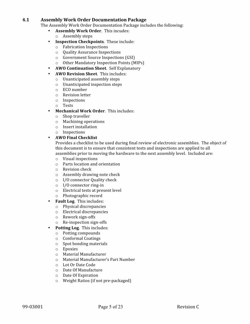
4.1 Assembly Work Order Documentation Package The Assembly Work Order Documentation Package includes the following:
• Assembly Work Order. This incudes: o Assembly steps
• Inspection Checkpoints. These include: o Fabrication Inspections o Quality Assurance Inspections o Government Source Inspections (GSI) o Other Mandatory Inspection Points (MIPs)
• AWO Continuation Sheet. Self Explanatory • AWO Revision Sheet. This includes:
o Unanticipated assembly steps o Unanticipated inspection steps o ECO number o Revision letter o Inspections o Tests
• Mechanical Work Order. This includes: o Shop traveller o Machining operations o Insert installation o Inspections
• AWO Final Checklist Provides a checklist to be used during final review of electronic assemblies. The object of this document is to ensure that consistent tests and inspections are applied to all assemblies prior to moving the hardware to the next assembly level. Included are: o Visual inspections o Parts location and orientation o Revision check o Assembly drawing note check o I/O connector Quality check o I/O connector ring-‐in o Electrical tests at present level o Photographic record
• Fault Log. This includes: o Physical discrepancies o Electrical discrepancies o Rework sign-‐offs o Re-‐inspection sign-‐offs
• Potting Log. This includes: o Potting compounds o Conformal Coatings o Spot bonding materials o Epoxies o Material Manufacturer o Material Manufacturer’s Part Number o Lot Or Date Code o Date Of Manufacture o Date Of Expiration o Weight Ratios (if not pre-‐packaged)

99-‐03001 Page 6 of 23 Revision C
• Configuration Traceability List. This includes:
o Individual Part Identification o Part Number o Part Description o Part Purchase Order Number o Part Serial Number o Part Lot-‐Date Code
• Kit Tag. The kit tag becomes the temporary nameplate for the subassembly during fabrication. It includes: o Assembly Drawing Number o Assembly Serial Number o Individual Preparing The Kit o Individual Inspecting The Assembly o Individual Fabricating The Assembly o Individual Accepting The Assembly Performance
• Material Status Tag. This includes: o Material or Part Name o Material Manufacturer o Material Distributor o Manufacturer’s Part Number o Lot Number o Purchase Order Number
• Reject Tag. This includes: o Part Name o Part Number o Reason for Rejection o Hardware Disposition

99-‐03001 Page 7 of 23 Revision C
5.0 Instructions for Completing the Assembly Work Order
Project The abbreviated form of the project name, i.e., XTE, AXAF, SAS-‐C, MJS, TESS, etc.
Assembly Name Name of the assembly. Page____of____ Page number and total number of pages in
the AWO. DWG No. The drawing used for the particular
assembly work. Build to Rev. The drawing revision used for the particular
assembly work, at the time of AWO issue. Assembly Serial No. The identifying number of the particular
assembly. Special Instructions Particular instruction required to perform
the assembly task but which may not be shown on the drawing (i.e. safety, or handling instructions).
Authorizing Engineer The particular engineer, as designated by the Project Manager, responsible for the particular assembly job.
Build Data Package Approval As determined by the project production supervisor.
Document Control The project Production Supervisor. R&QA Review and sign off of the assembly work
order by the cognizant Q.A. representative. Build History/Changes Incorporated Changes incorporated after the initial work
order is completed. Step No. A procedural step number. Type Electrical, mechanical, MKI QA, Customer
QA, Fabrication/Assembly, Inspection, or Test.
Description Brief description of the step to be performed.
Performed by The signature of the person performing the particular step.
Final Acceptance Project Manager or his designee, signature. R&QA The Reliability and Quality Assurance
Representative’s signature.

99-‐03001 Page 8 of 23 Revision C
Assembly Work Order Project: Page: of: Assembly Name:
Drawing Number:
Build To Rev.
Assembly Serial Number:
Special Instructions: Authorizing Engineer: Date: Build Data Package Approval:
Document Control
R&QA:
Build History/Changes Incorporated: Step No.
Type Description Performed By:
Date
Final Acceptance: Engineering:
Date R&QA: Date:
99-‐03001 Page 9 of 23 Revision C
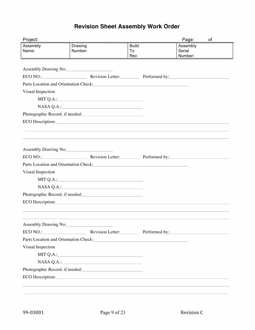
Revision Sheet Assembly Work Order
Project: Page: of Assembly Name:
Drawing Number:
Build To Rev.
Assembly Serial Number:
Assembly Drawing No: ECO NO.: Revision Letter: Performed by: Parts Location and Orientation Check: Visual Inspection MIT Q.A.: NASA Q.A.: Photographic Record, if needed: ECO Description: Assembly Drawing No: ECO NO.: Revision Letter: Performed by: Parts Location and Orientation Check: Visual Inspection MIT Q.A.: NASA Q.A.: Photographic Record, if needed: ECO Description: Assembly Drawing No: ECO NO.: Revision Letter: Performed by: Parts Location and Orientation Check: Visual Inspection MIT Q.A.: NASA Q.A.: Photographic Record, if needed: ECO Description:

99-‐03001 Page 10 of 23 Revision C
6.0 Instructions for Completing the Mechanical Work Order
Project Abbreviated form of the project name, i.e., XTE, AXAF, ASTRO-‐D, HEAO-‐B, TESS, etc.
Originator The cognizant Mechanical Engineer requesting the work. Approval Program Manager or Production Supervisor. CPY No. 3 copies are needed: one for the originator, one for the
production file, and one copy accompanies the work. Part No and rev. The drawing and revision number to which part or
assembly will be made. Part Description Part name QTY/Pld. Quantity per payload (gives and indication of spares). Req’d By Date parts are required. Engineer The cognizant Mechanical Engineer. Description of Work (quantity) brief description of the work order including the
quantity Operations Machine, plate, inspection, polish, etc. Location Location where the job will be performed. Signature Signature of the person performing the actual work. Remarks Special instructions Routing Pertains to outside machine shops. Topics are self-‐
explanatory. Close out Date work order Is completed. Comments On the job performance.

99-‐03001 Page 11 of 23 Revision C
Mechanical Work Order
Work Order MIT
Originator & Date Approval & Dates Copy No.
Part No:
Rev. Part Description: Qty/Pld: Req'd by: Engineer
Description of Work (including Quantity): Operations Location Signature Date Remarks: Routing Outside Close Out
Quotes Requested (Date) W.O. Closed (Date)
Quotes Received (Date) Comments: Successful Bidder (Date)
P.O. Let (Date)
Work Received (Date)

99-‐03001 Page 12 of 23 Revision C
7.0 Instructions for Completing the Assembly Fault log
Project The abbreviated form of the project name, i.e., XTE, AXAF, SAS-‐C, MJS, HEO-‐B, TESS, etc.
Assembly DWG No. The drawing used for the particular work order Ser. No. The identifying number of the particular assembly. Page ___ of ___ Number of pages required for the Fault Log. NO. The item number (discrepancy). Description A brief description of the problem. Originator The person first noting the discrepancy. MRB NO. Where appropriate, the Material Review Board action
number. ECO. Engineer Change Order No. associated with the problem
if appropriate. Rework and Re-‐Inspection The person responsible for re-‐work and the person
responsible for re-‐inspection.

99-‐03001 Page 13 of 23 Revision C
Assembly Fault Log Project: Assembly Dwg. No.____ Ser. No. Page of Disposition No. Date Description Originator MRB
No. ECO No.
Rework & Re-inspection
Remarks

99-‐03001 Page 14 of 23 Revision C
8.0 Instructions for Completing the Kit Tag
Project The abbreviated form of the project name, i.e., XTE, AXAF, SAS-‐C, MJS, HEO-‐B, TESS, etc.
Assembly Drawing No. Self Explanatory Assembly Ser. No. A unique number which identifies hat
particular subassembly or assembly from all other subassemblies or assembly of the same type.
Accepted by and Date The signature of the Project Engineer or his designee: month, day, and year.
Inspected by and Date The inspector’s signature or mark; month day and year.
Assembly Fabricated by and Date The person who fabricates the assembly or subassembly.
Kit Tag
Kavli Institute For Astrophysics and Space Research
Massachusetts Institute of Technology
Project:
Assembly Dwg. No.
Assembly Ser. No.
Kit Prepared By: Date:
Assembly Fabricated By: Date:
Assembly Inspected By: Date:
Assembly Tested By: Date:
Performance Accepted By: Date:

99-‐03001 Page 15 of 23 Revision C
Material Processing Mixing Record
ASSEMBLY NAME . DRAWING # . SERIAL # . INSPECT CURE
PROCESS TECH DATE
SURFACE PREP
LOT NUMBER
EXP DATE
MIX RATIO
OUT GAS
CONTR SAMPL
WITN SAMPL
HUM. TEMP
TIME
99-‐03001 Page 16 of 23 Revision C
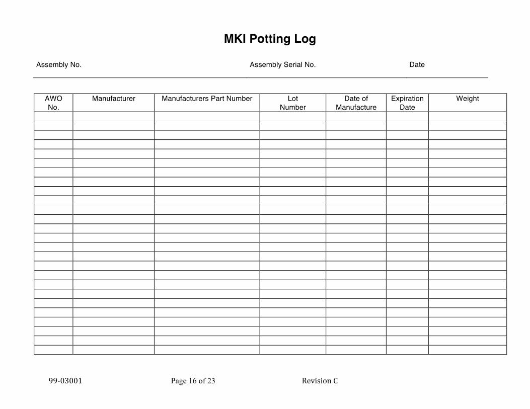
MKI Potting Log
Assembly No.
Assembly Serial No.
Date
AWO No.
Manufacturer Manufacturers Part Number Lot Number
Date of Manufacture
Expiration Date
Weight

99-‐03001 Page 17 of 23 Revision C
Connector Mate/Demate Log Project: Page of Assembly Name:
Drawing Number:
Build To Rev.
Assembly Serial Number:
CONN # DATE
M D
M D
M D
M D
M D
M D
M D
M D
M D M

99-‐03001 Page 18 of 23 Revision C
Configuration Traceability List PROJECT ________________________________ DATE _______________ ASSEMBLY NO _______________________ NAME ______________________________ S/N ___________ PAGE ____ OF ___ Special Instructions Assembly Name
Dwg. No.
Rev. Serial Number
Kitted By:
Part Dwg. No. Rev. No. Req
Description S/N Lot # Date Code
Remarks

99-‐03001 Page 19 of 23 Revision C
Conformal Coat Work Sheet Assembly Work Order
Project: Page: 1 of: Assembly Name: Drawing Number: Build To Rev. Assembly Serial No.:
SPECIAL INSTRUCTIONS:
-HANDLE PER MKI STATIC HANDLING PROCEDURE 99-01003 and ANSI ANSI/ESD S20.20,
-REFERENCE DOCUMENTS IPC-J-STD-001ES
Step No.
Type Description Perf By:
Date
1 I VERIFY CONFORMAL COAT LOT WITH TEST SAMPLE 2 P VERIFY ELECTRICAL TEST ACCEPTANCE 3 P VERIFY FINAL CHECKLIST SIGNED OFF 4 A CLEAN P.C. BOARD 4 -CLEAN AND SOAK USING REAGENT GRADE XYLENE
BLOW DRY WITH DRY NITROGEN
4 -SOAK AND RINSE USING REAGENT GRADE ISOPROPYL ALCOHOL BLOW DRY WITH DRY NITROGEN
4 -USE PINK ANTI-STATIC GLOVES FOR HANDLING BOARD
AFTER CLEANING
5 I MKI. Q.A. INSPECT FOR CLEANLINESS
6 A DRY P.C. BOARD BY EVACUATING @ 30 IN/MERCURY FOR 1/2 HOUR
START: DATE TIME FINISH : DATE TIME
7 A REMOVE FROM VACUUM SYSTEM AND BAG IN NEW ANTI-STATIC BAG
PURGE WITH DRY NITROGEN AND HEAT SEAL BAG.
8 A MOVE TO CLEAN BENCH -MASK LOCATIONS TO BE FREE OF CONFORMAL COATING USING
FLIGHT TAPE. LOCATIONS SPECIFIED BY ASSEMBLY DRAWING
-SPOT BOND COMPONENTS PER NASA-STS-8739.1 USING URALANE 5753A/B.
-CURE OVER NIGHT IN CLEAN BENCH. PLACE IN ANTI-STATIC BAG,
PURGE WITH NITROGEN AND SEAL.

99-‐03001 Page 20 of 23 Revision C
Crimp Connector Assembly Work Order
Project: Page: of: Assembly Name:
Drawing Number:
Build To Rev.
Assembly Serial Number:
J#/P# Connector Contact
Prepared By: R&QA Project
Step No.
Type Description Perf By:
Date
1 A PREPARE WIRES AND CRIMP CONTACTS PER NASA-SRD-8739.4 2 A PREPARE WIRES FOR CRIMPING -STRIP WIRES WITH MECHANICAL STRIPPER LABELLED
PER WIRE GAUGE WIRE STRIPPER SET #
-CLEAN WIRES USING WIPES AND ISOPROPANOL 3 A PREPARE CONTACTS FOR CRIMPING -BLOW OUT CONTACT BARREL USING COMPRESSED AIR -VISUALLY INSPECT CRIMP CONTACTS INSURING NO DEBRIS
IN CONTACT BARREL
4 A CRIMP TOOL QUALIFICATION -CRIMP TOOLS USED -TOOL: M22520/2-01 RECALIBRATION DATE - TURRET: M22520/2- 5 A/I TEST -GO/NO GO TEST WITH TOOL M22520/3-01 -VERIFY PULL TEST PERFORMED PER “TENSILE TEST DAILY LOG” 6 A/I CRIMP PINS/SOCKETS FOR CONNECTOR J#/P#
PER SCHEMATIC DRAWING REV
-CONNECTOR TYPE PER PARTS LIST -CONTACT TYPE -USE TOOL SPECIFIED IN STEP 4 -CRIMP TOOL SETTING WIRE TYPE #1 -CRIMP TOOL SETTING WIRE TYPE #2 -CRIMP TOOL SETTING WIRE TYPE #3 -VISUAL INSPECTION M.I.T. Q.A. 7 A INSERT CONTACTS IN CONNECTOR PER ATTACHED WIRING LIST -LABEL CONTACT PIN #'S ON WIRES 8 A/I VERFIY PIN RETENTION M.I.T. Q.A. 9 A CLEAN, BAG, AND TAG HARNESS; INSTALL CONN COVERS 10 A STORE IN FLIGHT ASSEMBLY AREA FOR NEXT LEVEL
OF ASSEMBLY

99-‐03001 Page 21 of 23 Revision C
Solder Connector Assembly Work Order
Project: Page: of: Assembly Name:
Drawing Number:
Build To Rev.
Assembly Serial Number:
Build History/Changes Incorporated:
Step No.
Type Description Perf By:
Date
1 SOLDER WIRES IN CONNECTOR # PER SCHEMATIC:
-BLOW OUT SOLDER CUPS -INSPECT SOLDER CUPS INSURE FREE OF DEBRIS AND INSURE
THAT GOLD PLATING IS FREE OF FLAWS
-TIN CUPS AND REMOVE SOLDER (3X) -AVOID SPILLOVER -INSTALL WIRES PER SCHEMATIC -CUT AND STRIP WIRES -INSPECT STRIPS -TIN WIRES -INSPECT TINNING -SOLDER WIRES IN CUPS -CLEAN EACH SOLDER CONNECTION AFTER SOLDERING,
USE ISOPROPANOL.
-AFTER ALL CONNECTIONS MADE CLEAN CONNECTIONS USING XYLENE AND RINSE USING ISOPRPOANOL.
-INSPECT
M.I.T. QA ONR -SLEEVE CONNECTIONS USING SHRINK TUBING

99-‐03001 Page 22 of 23 Revision C
Assembly Work Order Final Check List
Project: Page: Of: Assembly Name:
Drawing Number:
Build To Rev.
Assembly Serial Number:
A. Revision Check -Latest Revision Letter in ECO Book: -Latest Revision Letter performed per Revision Sheet: B. Parts location and orientation check per Assembly Drawing -Assembly Drawing No: Revision Letter -Performed by: C. Assembly Drawing Note Check: -Performed by: D. I/O Connector Quality Check: -Sockets - Retention Check - Performed by: -Pins - Push Test - Performed by: E. I/O Connector Ring-in -Performed by: F. Visual Inspection -MIT Q.A.: -NASA Q.A.: G. Electrical Test -Performed by: H. Photographic Record

99-‐03001 Page 23 of 23 Revision C
MKI Reject Tag
MKI
REJECT Tag KAVLI CENTER FOR SPACE RESEARCH
Massachusetts Institute of Technology Project: Date
Part Name: Part No.
Reason for Rejection:
Disposition
Inspector:


![Perf Test Guide[1].2007 08 27](https://static.fdocuments.us/doc/165x107/55531d74b4c905a7778b4a9b/perf-test-guide12007-08-27.jpg)