Maskell - Wake Correction
27
'R. & . .3-400' MINSTR OFAVATO AgRONAUtIAREERHCJNU A rri-D ^ 1 j- V,4 4 :i-ptc, ^in, P.____A t i 11m 1 imuV1Y VI Lim~ %-FLA.L %A.. and Stalled Wings in a Closed Wind Tunnel By E. C. MASKELL LONDON: HER~ MAJESTY'S STATIONERY OFFICE~ t9g65 smc
-
Upload
santiago-f -
Category
Documents
-
view
65 -
download
2
Transcript of Maskell - Wake Correction
'R. & . .3-400'
MINSTR OFAVATO
AgRONAUtIAREERHCJNU
A rri-D ^ 1 j- V,44 :i-ptc, ^in, P.____A t i
11m 1 imuV1Y VI Lim~ %-FLA.L %A..
and Stalled Wings in a Closed Wind TunnelBy E. C. MASKELL
LONDON: HER~ MAJESTY'S STATIONERY OFFICE~
t9g65
smc
A Theory of the Blockage Effects on Bluff Bodiesand Stalled Wings in a Closed Wind Tunnel
By E. C. MASKELL,
COMMUNICATED BY THE DEPUTY CONTROLLER AIRCRAFT (RESEARCH AND DEVELOPMENT),
MINISTRY OF AVIATION
Reports and Memoranda No. 3400*
November, 1963
Sumtnwry.
A theory of blockage constraint on the flow past a bluff body in a closed wind tunnel is developed, usingan approximate relation describing the momentum balance in the flow outside the wake, and two empiricalauxiliary relations. The theory is well supported by experiment and leads to the correction formula
Aq/q = cCDSI/C
where Aq is the effective increase in dynamic pressure due to constraint, and c is a blockage factor dependenton the magnitude of the base-pressure coefficient. The factor c is shown to range between a value a littlegreater than 5J2 for axi-symmetric flow to a little less than unity for two-dimensional flow. But the variationfrom 5/2 is found to be small for ,spect ratios in the range I to 10.
The theory is extended to stalled wings, and an appropriate technique for the correction of wind-tunneldata is evolved.
LIST OF CONTENTS jAcession ForSection TIS GRA&I
I. Introduction DTIC TAB
2. Bluff Bodies JUn a tiou
2.1 Properties of the bluff-body wake
2.2 Invariance under constraint !;3Y31 Distribution/2.3 Conservation of momentums Availability
Codes
2.4 Distortion of the wake IAvail and/or
2.5 Blockage correction Avist nSpecoial.
2.6 Discussion
2.7 Comparison with experiment
2.7.1 A = 12.7.2 A = oo2.7.3 The effect of aspect ratio UNANNOUNCED
Replaces RA.E. Report No. Acro. 2685--A.R.C. 25 730. C
SLTE
Er
LIST OF CONTENTS-continuedSection
3. Stalled Wings
3.1 Properties of the wake
3.2 Recommended forms of correction3.2.1 Finite span3.2.2 Infinite span
4. Concluding Remarks
Symbols
References
Illustrations-Figs. I to 11
Detachable Abstract Cards
LIST OF ILLUSTRATIONSFigure
1. Model of flow
2. Invariance of the ratio CD /?k for non-lifting square plates
3. The effect of constraint on the lateral distribution of pressure 1 4l behind a squarefl at plate
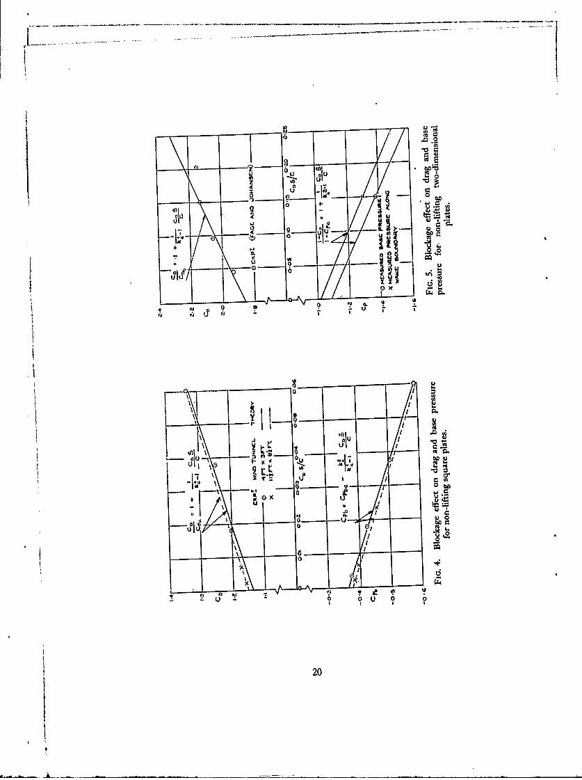
4. Blockage effect on drag and base pressure for non-lifting square plates
5. Blockage effect on drag and base pressure for non-lifting two-dimensional plates
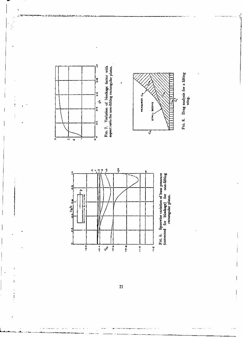
6. Spanwise variation of base pressure (corrected for blockage) for non-liftingrectangular plates
7. Variation of blockage factor with aspect ratio for non-lifting rectangular plates
S. Drag analysis for a lifting wing
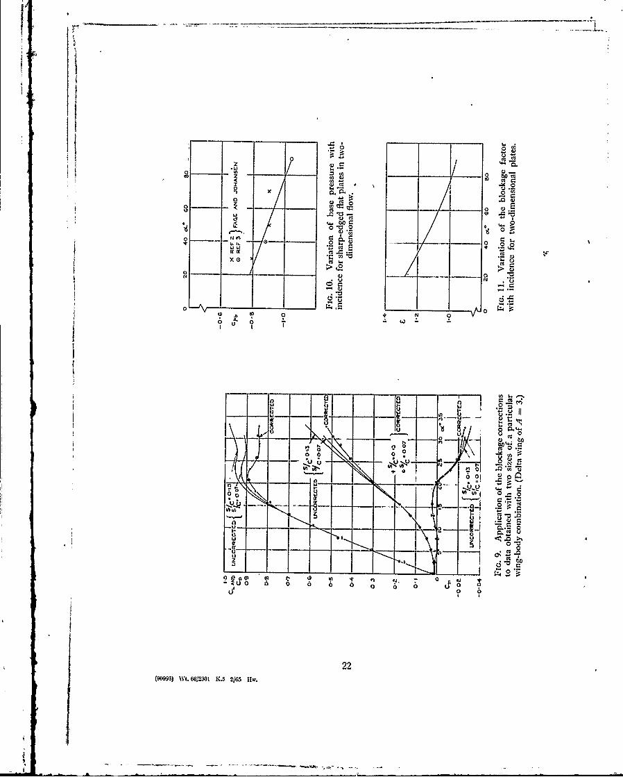
9. Application of the blockage corrections to data obtained with two sizes of aparticular wing-body combination (delta wing of A = 3)
10. Variation of base pressure with incidence for sharp-edged flat plates in two-
dimeqsional flow
11. Variation,.of the blockage factor with incidence for two-dimensional plates
1. Introduction.
The flow past a symmetrical body immersed in an airstream bounded by rigid walls is subjecttip what is commonly called blockage constraint. The rigid boundaries prevent a free lateraldisIdlacement of the airflow by the body, in the neighbourhood of \ hich \elocities are higher than
2

they would be in an unlimited stream. The dominant effect is usually taken to be equivalent to a
simple increase in the free-stream velocity, related in part to the volume distribution of the bodyitself (solid blockage), and in part to the displacement effect of the wake (wake blockage). Approrpriate correctons to me observed velocity of the stream can be calculated by standard methods,provided that the given body gives rise to an essentially streamline flow.
Little attention has been given to wall constraint on the non-streamline flow past a bluff body or,
more generally, a stalled wing, since Glauert's' treatment of the two-dimensional problem in 1933.Glauert's interest in the problem appears to have been stimulated by the experiments of Fage andJohansen2,3 on the flow past an inclined flat plate spanning a wind tunnel. He pointed out thenature of the blockage effect associated with the thick bluff-body wake, and his remarks led Fageand Johansen to test several plates of different sizes and hence, by extrapolation to zero chord, toestablish the drag coefficient of a two-dimensional flat plate normal to an unlimited stream. Mean-while Glauert proposed a theory, based in part upon the Helmholtz model of the flow past a bluffbody, according to which the drag D, in an unlimited stream is related to the drag D in the windtunnel by %
De = D l-h]
where t is the thickness of the bluff base, h the tunnel height, and q an empirical factor. But thepresence of the empirically determined q reduces Glauert's formula to an interpolation betweenknown experimental results, which are not sufficiently accurate to give adequate support to theproposed functional dependence upon ilh. The formula seems not to have been widely used, thewake blockage correction
Aq I C Sq 2
(where Aq is the effective increment in the dynamic pressure of the undisturbed stream, S therepresei,,ative area on which the profile drag coefficient CDo is based, and C the cross-sectionalarea of the tunnel) generally being preferred to it.* However, there is little doubt that the lattercorrection holds only for streamline flow, and that the bluff-body problem requires a differenttreatment.
This paper presents a simple theory of the constraint which is well supported by observation.Interest in the problem, especially in its three-dimensional form, was revived when markeddifferences were noticed in the high-lift characteristics of models of a particular aircraft tested indifferent wind tunnels. The models in question were basically delta wings of moderately smallaspect ratio. And from the onset of stall, which began at the wing tips and then spread inboard withincreasing incidence, the different sets of results could be reconciled only through some form ofwall interference grossly bigger than those covered by the standard corrections. The purpose of thepresent investigation, therefore, was to establish the existence of such an interference more con-vincingly and then to provide appropriate corrections for it.
Since it was evident, from the outset, that the effect was connected with the breakdown ofstreamline flow over the wing, it seemed worth while to concentrate attention, in the first instance,upon the extreme situation occurring when a wing-like shape-for example, a thin flat plate-is set
* See, for example, Pankhurst and Holder4.
3(90995)A2
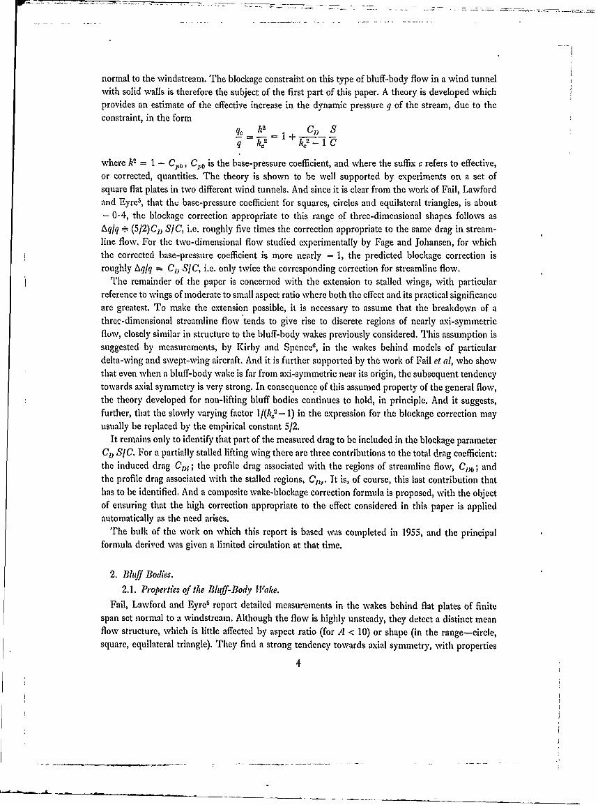
normal to the windstream. The blockage constraint on this type of bluff-body flow in a wind tunnelwith solid walls is therefore the subject of the first part of this paper. A theory is developed whichprovides an estimate of the effective increase in the dynamic pressure q of the stream, due to theconstraint, in the form
q_ k2 CD S
q k,:' k 2 -
where k2 = 1 - C ,, CI,b is the base-pressure coefficient, and where the suffix c refers to effective,or corrected, quantities. The theory is shown to be well supported by experiments on a set ofsquare flat plates in two different wind tunnels. And since it is clear from the work of Fail, Lawfordand Eyre,, that tht base-pressure coefficient for squares, circles and equilateral triangles, is about- 0.4, the blockage correction appropriate to this range of three-dimensional shapes follows asAqlq - (5/2)CjD SIC, i.e. roughly five times the correction appropriate to the same drag in stream-line flow. For the two-dimensional flow studied experimentally by Fage and Johansen, for whichthe corrected base-pressure coefficient is more nearly - 1, the predicted blockage correction isroughly Aq/q = CD SIC, i.e. only twice the corresponding correction for streamline flow.
rTihe remainder of the paper is concerned with the extension to stalled wings, with particularreference to wings of moderate to small aspect ratio where both the effect and its practical significanceare greatest. To make the extension possible, it is necessary to assume that the breakdown of athree-dimensional streamline flow tends to give rise to discrete regions of nearly axi-symmetricfluw, closely similar in structure to the bluff-body wakes previously considered. This assumption issuggested by measurements, by Kirby and SpenceG, in the wakes behind models of particulardelta-wing and swept-wing aircraft. And it is further supported by the work of Fail et al, who showthat even when a bluff-body wake is far from axi-symmetric near its origin, the subsequent tendencytowards axial symmetry is very strong. In consequence of this assumed property of the general flow,the theory developed for non-lifting bluff bodies continues to hold, in principle. And it suggests,further, that the slowly varying factor 1/(k,
2- 1) in the expression for the blockage correction mayusually be replaced by the empirical constant 5/2.
It remains only to identify that part of the measured drag to be included in the blockage parameterCI) SIC. For a partially stalled lifting wing there are three contributions to the total drag coefficient:the induced drag CDp; the profile drag associated with the regions of streamline flow, C1 O; andthe profile drag associated with the stalled regions, C,. It is, of course, this last contribution thathas to be identified. And a composite wake-blockage correction formula is proposed, with the objectof ensuring that the high correction appropriate to the effect considered in this paper is appliedautomatically as the need arises.
The bulk of the work on which this report is based was completed in 1955, and the principalformula derived was given a limited circulation at that time.
2. Bliff Bodies.
2.1. Properties of the Bhiff-Body Wake.
Fail, Lawford and Eyre5 report detailed measurements in the wakes behind flat plates of finitespan set normal to a windstream. Although the flow is highly unsteady, they detect a distinct meanflow structure, which is little affected by aspect ratio (for A < 10) or shape (in the range-circle,square, equilateral triangle). They find a strong tendency towards axial symmetry, with properties
4
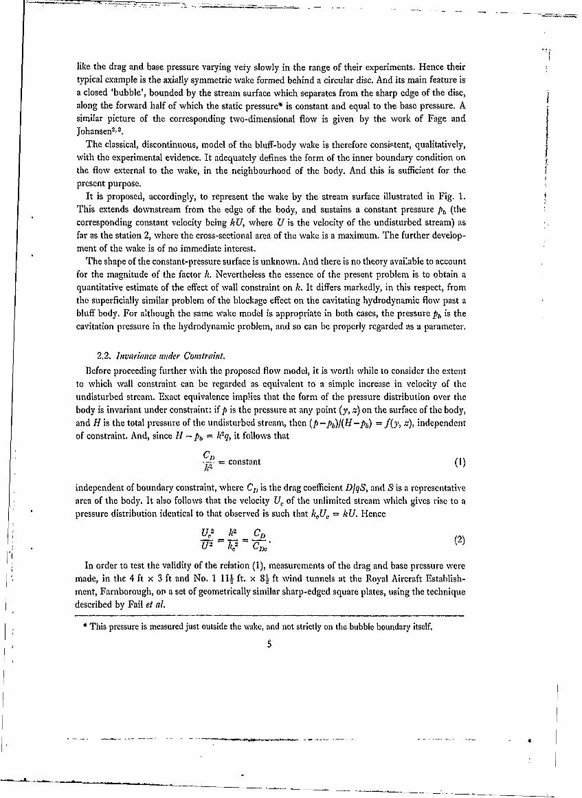
like the drag and base pressure varying very slowly in the range of their experiments. Hence theirtypical example is the axially symmetric wake formed behind a circular disc. And its main feature isa closed 'bubble', bounded by the stream surface which separates from the sharp edge of the disc,along the forward half of which the static pressure* is constant and equal to the base pressure. Asimilar picture of the corresponding two-dimensional flow is given by the work of Fage andJohansen2 ,3.
The classical, discontinuous, model of the bluff-body wake is therefore consistent, qualitatively,with the experimental evidence. It adequately defines the form of the inner boundary condition on
the flow external to the wake, in the neighbourhood of the body. And this is sufficient for thepresent purpose.
It is proposed, accordingly, to represent the wake by the stream surface illustrated in Fig. 1.This extends downstream from the edge of the body, and sustains a constant pressure Pb (thecorresponding constant velocity being kU, where U is the velocity of the undisturbed stream) asfar as the station 2, where the cross-sectional area of the wake is a maximum. The further develop-ment of the wake is of no immediate interest.
The shape of the constant-pressure surface is unknown. And there is no theory avai:able to accountfor the magnitude of the factor k. Nevertheless the essence of the present problem is to obtain aquantitative estimate of the effect of wall constraint on k. It differs markedly, in this respect, fromthe superficially similar problem of the blockage effect on the cavitating hydrodynamic flow past abluff body. For although the same wake model is appropriate in both cases, the pressure Pt, is thecavitation pressure in the hydrodynamic problem, and so can be properly regarded as a parameter.
2.2. Invariance under Constraint.
Before proceeding further with the proposed flow model, it is worth while to consider the extentto which wall constraint can be regarded as equivalent to a simple increase in velocity of theundisturbed stream. Exact equivalence imphies that the form of the pressure distribution over thebody is invariant under constraint: if p is the pressure at any point (y, -) on the surface of the body,and H is the total pressure of the undisturbed stream, then (p-p)I(H-p) = fOy, z), independentof constraint. And, since H - Pb = k2q, it follows that
VkS = constant (1)
independent of boundary constraint, where C) is the drag coefficient D]qS, and S is a representativearea of the body. It also follows that the velocity U, of the unlimited stream which gives rise to apressure distribution identical to that observed is such that kU, = kU. Hence
U ,2" k 2 C D- =(2)
U2 - J-),
In order to test the validity of the relation (1), measurements of the drag and base pressure weremade, in the 4 ft x 3 ft and No. 1 111 ft. x 8k ft wind tunnels at the Royal Aircraft Establish-ment, Farnborough, or a set of geometrically similar sharp-edged square plates, using the techniquedescribed by Fail et al.
* This pressure is measured just outside the wake, and not strictly on the bubble boundary itself.
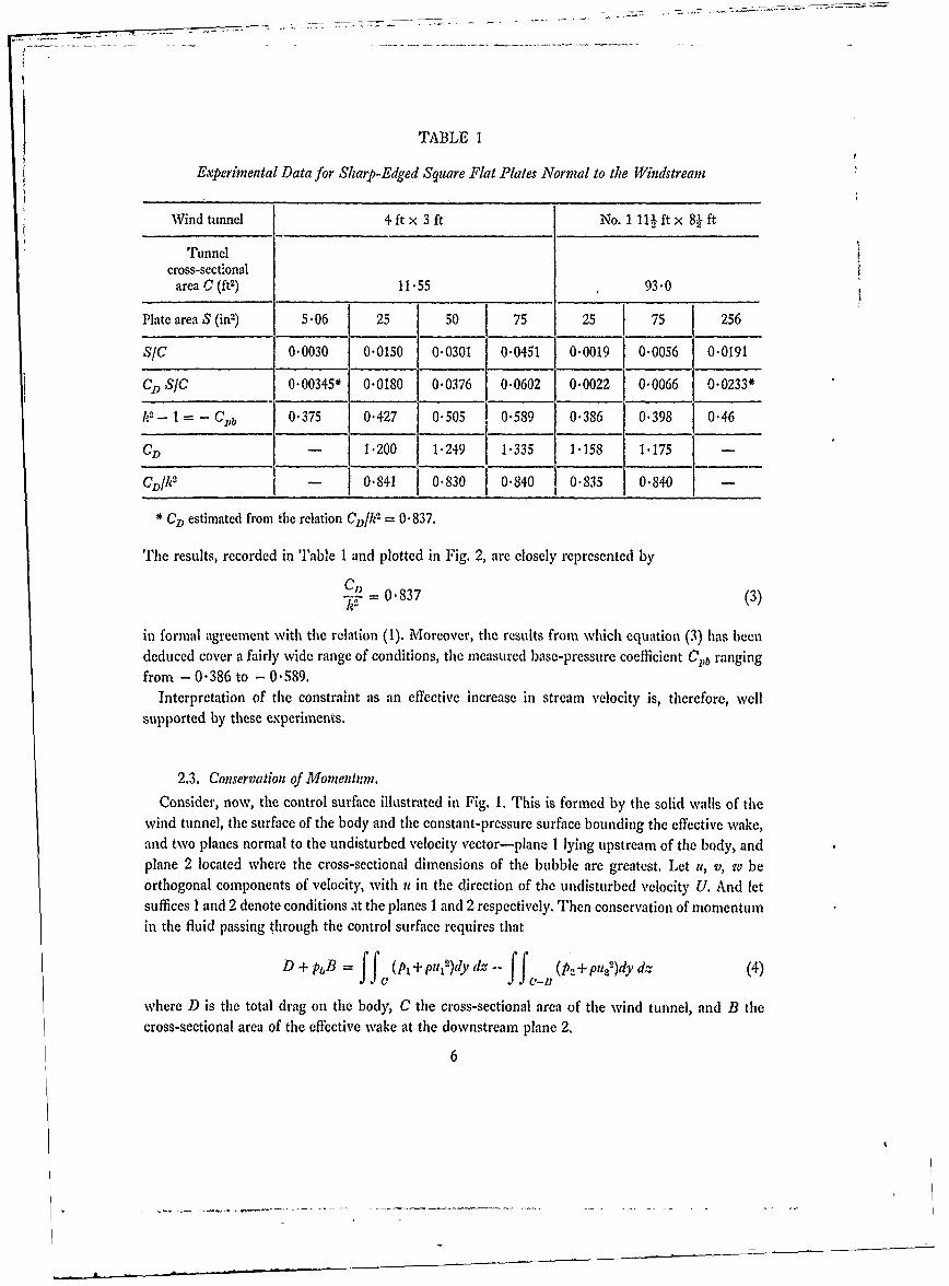
TABLE 1
Experinental Data for Sharp-Edged Square Flat Plates Normal to the Windstream
Wind tunnel 4ftx 3ft No. 1 1U ft x 81 ft
Tunnelcross-sect-onal
area C (ft2) 11.55 - 93.0
Plate area S (in) 5-06 25 50 75 25 75 256
S/C 0-0030 0.0150 0-0301 0-0451 0.0019 0-0056 0-0191
CD S/C 0.00345* 0-0180 0-0376 0.0602 .0022 0-0066 0.0233*
k- 1 - C b 0-375 0-427 0-505 0-589 0-386 0-398 0-46
CD - 1.200 1.249 1-335 1-158 1.175 -
CDk 2 - f 0-841 0-830 0-840 0-835 0-840 -
* CD estimated from the relation ClGk 2 = 0-837.
The results, recorded in Table 1 and plotted in Fig. 2, are closely represented by
C = 0-837 (3)
in formal agreement with the relation (1). Moreover, the results from which equation (3) has beendeduced cover a fairly wide range of conditions, the measured base-pressure coefficient Cvb rangingfrom - 0386 to -0-589.
Interpretation of the constraint as an effective increase in stream velocity is, therefore, wellsupported by these experiments.
2.3. Conservation of Momennin.
Consider, now, the control surface illustrated in Fig. 1. This is formed by the solid walls of thewind tunnel, the surface of the body and the constant-pressure surface bounding the effective wake,and two planes normal to the undisturbed velocity vector-plane I lying upstream of the body, andplane 2 located where the cross-sectional dimensions of the bubble are greatest. Let it, v, w beorthogonal components of velocity, with it in the direction of the undisturbed velocity U. And letsuffices 1 and 2 denote conditions at the planes 1 and 2 respectively. Then conservation of momentumin the fluid passing through the control surface requires that
D + pB =ff (Pt + pu'12 )dy dz -- (p2 + p 2
2 )dy dz (4)
where D is the total drag on the body, C the cross-sectional area of the wind tunnel, and B thecross-sectional area of the effective wake at the downstream plane 2.
6
Since the fluid is wholly outside the wake, Bernoulli's equation gives
P1 + p(u.12+v 1
2 +w12 ) = P 2 + p(u2
2 +V22 +w 2
2) P + jpU2
where P, U are the pressure and velocity in the undisturbed stream. And equation (4) may bewritten
D =(P-Pb,)B + pU 2B + ffjpU12dy dZ -jj ff p 24dY dz +
ffad fc-B
+ ff _ p(v22 + w 2)dy dz - f f p(v1
2 + w12,)dy dz. (5)
Now the work of Fail et al suggests that the wake is likely to be cle3ely axi-symmetric in theneighbourhood of the plane 2, for most three-dimensional bodies of practical interest. Hence, withthe plane 1 chosen to lie far upstream, the contribution from the last two integrals in equation (5)is likely to be negligibly small. Since the same conclusion holds equally well for a two-dimensionalbluff-body flow, it follows that, for almost all bodies of practical interest, equation (5) can bereduced to
D = -pk2U2B + f f pu12dy dz - 2 pu22dy dz (6)
sincePb + pk 2U2 = P + pU 2 .
Now write1I = U + u1'
it.= U. + U.,
where
ff o l'dy ,lz = ff ud.'dy dz = 0
so that U is the mean velocity over the plane 1 (i.e. the velocity of the undisturbed stream) and U2
is the mean velocity over the plane 2 outside the wake. Then, for continuity,
UC = U(C-B) (7)
and equation (6) may be written
D = Apk 2U2B - -pU2B I+ f f u112dy dz- ff .pu 2
12dy dz. (8)
Assuming that It,' and it' are sufficiently small for the integrals remaining in (8) to be neglected,the following relation for the drag coefficient is obtained
C)= r(k 2 - 1 - mSIC) (9)
where m = BIS, and where (mSIC)2 is taken to be negligibly small.Data obtained by Fail et al for a circular disc normal to the stream in the 4 ft x 3 ft wind tunnel
are in close agreement with equation (9). With S = 25 in2, S/C = 0.015, the measured base-pressure coefficient was - 0.425 and the drag coefficient 1.18. From measurements of the velocityfield in the wake, the radius of the maximum cross-section of the bubble was approximately4.9 inches, and the displacement thickness of the vortex layer outside the bubble at the same
7
cross-section was approximately, 0" 08 inches. Hence, since the wake boundary of the mathematicalmodel should coincide with the displacement boundary of the true wake, rather than with theobserved bubble boundary, for the present purpose
B = r4"982 in2
givingm = 3.12.
Then, from (9)
CD = 3.12(0.425 -0- 047) = 1 179
compared with the measured 1- 18.
2.4. Distortion of the Wake.
A relation between CDC, k. and in,, appropriate to the equivalent unlimited stream, is obtainedby putting SIC = 0 in equation (9). Then, using (1) and (9)
CD C (21fl/C In 0 1)=cosk2 = F -2 (k2- 1 -mSIC = n (k,2- 1
) = eonst. = In* (k2- 1). (10)
But the equations (10) are not sufficient to define the blockage effect completely. A further relationis required, to account for the distortion of the wake under constraint. This involves considerationsoutside the scope of the theory developed so far.
The significance of distortion is easy to demonstrate. So far as the equations (10) are concerned,constraint could give rise solely to distortion of the wake, the pressure distribution over the body,and hence k, remaining invariant. In that case i, would take the value m*, and the blockage velocitywould be zero. On the other hand, if there were no distortion, the required auxiliary relation wouldbe simply
,fe =In
which, combined with equations (10), leads to
CI= k2 -+ Cl, SC, , 2 k 1 1 I' (11)
This relation can be compared with the data obtained with the set of square flat plates in the4 ft x 3 ft wind tunnel, for which extrapolation to SIC = 0 gives C& = 1.139, k 2 - 1 = 0.361.Then, according to (11)
~S= I + 3.15 S
leading to CI) = 1.142 CI) at SIC = 0.045 (the highest value of SIC reached in the experiments)compared with the measured C1) = 1 335 = . 172 CD, Thus it appears that equation (11)underestimates the apparent increase in drag coefficient due to constraint by nearly 200. And inview of the close agreement between experiment and the equations (1) and (9) an attempt to takesome account of wake distortion is evidently desirable. To do this theoretically would involve agreater understanding of the internal mechanics of the wake than is available at the present time.The problem, therefore, is to find a suitable empirical relation between mn, and in.
8
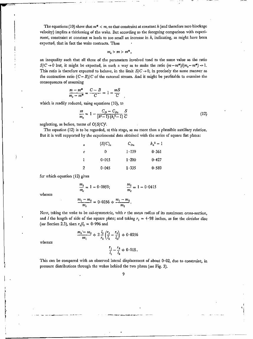
The equations (10) show that n* < in, so that constraint at constant k (and therefore zero blockagevelocity) implies a thickening of the wake. But according to the foregoing comparison with experi-ment, constraint at constant rn leads to too small an increase in k, indicating, as might have beenexpected, that in fact the wake contracts. Thus
in, > m > in*,
an inequality such that all three of the parameters involved tend to the same value as the ratioS/C -> 0 but, it might be expected, in such a way as to make the ratio (in - mn*)/(m- mn*)-- 1.This ratio is therefore expected to behave, in the limit SIC -+0, in precisely the same manner asthe contraction ratio (C- B)/C of the external stream. And it might be profitable to examine theconsequences of assuming
mi - n* C-B inSmi-iZ m* C C
which is readily reduced, using equations (10), to
. = 1 Cs- C,, S (12)
il,, (k2- 1) (k- 1) C
neglecting, as before, terms of O(SC)2.The equation (12) is to be regarded, at this stage, as no more than a plausible auxiliary relation.
But it is well supported by the experimental data obtained with the series of square flat plates:
(SfC),, CM),, k,2- I
0 1.139 0.361
1 0.015 1.200 0.427
2 0.045 1.335 0.589
for which equation (12) gives
= 1- 0.0059; = 1- 0.0415me 7inc
whence
minmx- =0.0356-n -n:
Now, taking the wake to be axi-symmetric, with r the mean radius of its maximum cross-section,and I the length of side of the square plate; and taking r1 = 4'98 inches, as for the circular disc(see Section 2.3), then r/l1 = 0.996 and
11 1 1 12 i n 4 I ( L I _ 3 5 6
-_ .0356in,1 r, 1 , 1'2!
whence11 12 0.018.11 l'2
This can be compared with an observed lateral displacement of about 0-02, due to constraint, inpressure distributions through the wakes behind the two plates (see Fig. 3).
9

2.5. Blockage Correction.
From equations (10) and (12), it follows that
k2 C ST2 k = 1 + - I + o{(S/C)2} (13)
so that the effect of distortion is to replace CDC in the correction term of equation (11) by the
measured CD. Alternatively, writing q for the dynamic pressure and using (2), this result may bewritten Aq cDs
-= CS (14)q C
where Aq = q, - q is the effective increase in dynamic pressure of the undisturbed stream due toconstraint, CD SIC is the usual wake blockage parameter, and where
1k - (15)
is the so-called blockage factor for the bluff-body flow.
In order to determine e, given measured values of k and CI), it is necessary to find k. 2 fromequation (13). It is not normally sufficient to replace k. 2 in (15) by k2. An iterative solution of (13)has been found convenient, using the formula
2 ( 1 + ( 2 1-' (16)k 1" (k0
2),,_4 - 1 C
where (k0 ) is the nth approximation to k.2, and with (k2)0 = k2.
Measured values of drag and pressure coefficients can now be corrected to the effective dynamic
pressure q., according to1 -C, C) " (17)1-C 0 c DCo -0 ko2 -q
2.6. Discussion.
So far the base pressure has been assumed uniform. But this is not necessary. A mean basepressure can be defined by
A f f p dy dz
the integral being taken over the base of the body and over the surface of the effective wake. With
Pb so defined, equation (4) remains unchanged, and equation (9) follows to the same order of approxi-mation as before. It appears that even a substantial non-uniformity in base pressure need notinvalidate the theory. It is reasonable to suppose, therefore, that the theory holds for almost alltwo-dimensional bluff-body flows, and for the wide range of three-dimensional flows for which thewake is closely axi-symmetric at the downstream plane 2.
There is one important possible exception to this rule. An implied assumption in the theory isthat the origin of the wake (i.e. boundary-layer separation on the body) is independent of constraint.And so it may be necessary to exclude well-rounded bluff bodies (like the circular cylinder), for whicha small change in pressure distribution might lead to a significant movement of the separation front.
With the base pressure uniform, it is evidently possible to determine the blockage factor e froma single measurement of static pressure somewhere on the base of the body. It is then a simple
10

matter to provide for this measurement in the design of a wind-tunnel model. But since with a
non-uniform base pressure it is strictly necessary to measure the detailed pressure distributionover the entire base of the body and over the surface ofthe wake, it is fortunate that the experimentalevidence analysed below suggests that it is probably sufficient, for most practical purposes, to take
6 -1 for two-dimensional flow and e - 5/2 for three-dimensional flow.
2.7. Comparison with Experiment.
2.7.1. A = 1.-The best available test of the theory is provided by the data obtained inthe experiments on a set of geometrically similar sharp-edged square plates, recorded in Table 1,to which reference h.. already been made. In these experiments the base pressure was found to beclosely uniform, so that determination of the parameter k was straightforward. The principal resultshave been shown (Fig. 2) to be closely represented by the relation (3), viz. CD/k2 = 0'837. Onlybase pressures could be measured on two of the plates (the smallest in the 4 ft x 3 ft wind tunneland the largest in the No. 1 11 ft x 81 ft wind tunnel). The corresponding drag coefficientshave theribre been estimated from the relation (3), in order to allow subsequent correction of theobserved pressures.
Independent solutions of equation (13) provide two groups of corrected base-pressure coefficients,one for each wind tunnel. These are recorded in Table 2.
TABLE 2
Corrected Base Pressure Coefficients for Non-Lifting Square Plates
4 ft x 3 ft wind tunnel No. 11 K ft x 81 ft wind tunnel
CoS - b - boD_ - Cpb - Cpbo
C (2-1) VV,- 1) C (k2-1) (k2- 1)
0.00345 0.375 0.362 0.0022 0.386 0.3780.0180 0.427 0.360 0.0066 0.398 0.3730.0376 0.505 0.363 0.0233 0.460 0.3750.0602 0.589 0.360
Mean 0.361 Mean 0.375
The systematic difference between the two groups of corrected results, though difficult to explain,*is not relevant to the present investigation. What matters here is the very close agreement betweenthe results in each group. This strongly supports the theory.
* Great care was taken to avoid significant experimental errors. All the observed results quoted are mean
values of several independent observations showing, as a rule, less than ± 1% scatter. In particular, eachdrag coefficient is an average of about ten separate readings of the drag balance, usually taken over a periodof several days. Furtlermore, each wind tunnel was recalibrated during the investigation, with special referenceto the flow in the neighbourhood of the models. The more obvious sources of error therefore appear to beruled out. There remains a marked difference in turbulence level of the two airstreams: in the 4 ft x 3 ftwind tunnel, the r.m.s. value of the streamwise component of the turbulent velocity is known to be about0.01% of the undisturbed velocity, whereas the corresponding figure for the No. 1 11 ft x 8. ft windtunnel is likely to be nearer 0.5%.
11

The corresponding corrected values of the, drag coefficient follow from (17), and are listed inTable 3.
TABLE 3
Corrected Drag Coefficients for Non-Lifting Square Plates
4 ft x 3 ft wind tunnel No. I 11j ft x 8j ft wind tunnel
CDS CD-w C~0 C D
0.0180 1.200 1.143 0.0022 1.158 1.1510.0376 1.249 1'131 0.0066 1,. 175 1.1540.0602 1.335 1.144
Mean 1.139 Mean 1.152
Here again the results support the theory very well. Moreover, it is worth noting that both pairs ofmean values defined in the tables satisfy relation (3) almost exactly, viz.
C,_ 1.139 1.152- = T3=61 1375 = 837.
These mean values, together with the relations (13) and (17), lead to the graphical comparison
between theory and experiment shown in Fig. 4.
2.7.2. A = oo.-Data given by Fage and Johansen2' , for a set of four thin flat plates,spanning a 7 ft wind tunnel, provide further support for the present theory. However, the dataare rather less complete than for the square plates considered above, since detailed measurementsof the flow were made behind only one plate.
Fage and Johansen found the pressure along the surface of the wake to be constant, within theaccuracy of measurement, but to be slightly greater than the constant pressure measured on the rearsurface of the plate. The pressure Pb appropriate to the theory must consequently be defined accord-ing to Section 2.6. It is not, in this case, directly equal to the measured base pressure. The relevantdata are: SIC = 0.0715, C) = 2.13, base-pressure coefficient - 1.38, mean pressure coefficientalong wake boundary - I .30, and the maxinium width off the wake I -85 times the breath of theplate. Hence the mean base-pressure coefficient from which the parameter k is to be determined,is - 1.34.
Now, solving equation (13) for k,, gives
e = 1/1.04 = 0.962
and, by (14) and (17), the set of corrected drag coefficients given in Table 4 are obtained from themeasured values given by Fage and Johansen.The fourth estimate of C') in this set is rather lower than the others, perhaps because at so large avalue of the blockage parameter Co) SIC the pressure distribution over the plate becomes distorted.The mean value quoted in the table is therefore based on the first three results. The relations (13)and (17) then lead to the comparison between theory and experiment illustrated in Fig. 5.
12
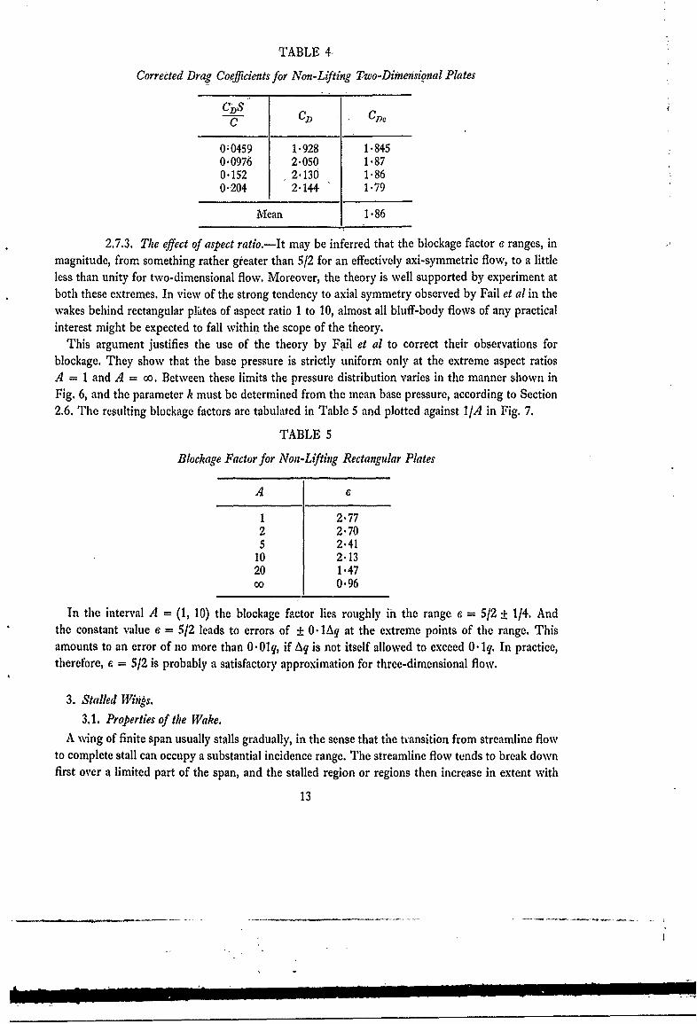
TABLE 4
Corrected Drag Coefficients for Non-Lifting Two-Dimensional Plates
C CD
0;0459 1.928 1.8450.0976 2.050 1.870"152 2'130 1"860"204 2"144 1"79
Mean 1.86
2.7.3. The effect of aspect ratio.-It may be inferred that the blockage factor e ranges, inmagnitude, from something rather greater than 5/2 for an effectively axi-symmetric flow, to a littleless than unity for two-dimensional flow. Moreover, the theory is well supported by experiment atboth these extremes. In view of the strong tendency to axial symmetry observed by Fail et al in thewakes behind rectangular phites of aspect ratio 1 to 10, almost all bluff-body flows of any practicalinterest might be expected to fall within the scope of the theory.
This argument justifies the use of the theory by Fail et al to correct their observations forblockage. They show that the base pressure is strictly uniform only at the extreme aspect ratiosA = I and A = oo. Between these limits the pressure distribution varies in the manner shown inFig. 6, and the parameter k must be determined from the mean base pressure, according to Section2.6. The resulting blockage factors are tabulated in Table 5 and plotted against 1/A in Fig. 7.
TABLE 5
Blockage Factor for Non-Lifting Rectangular Plates
A 6
1 2.772 2.705 2.41
10 2.1320 1.47o 0.96
In the interval A = (1, 10) the blockage factor lies roughly in the range e = 5/2 + 1/4. And
the constant value e = 5/2 leads to errors of ± 0. lAq at the extreme points of the range. This
amounts to an error of no more than 0.Olq, if Aq is not itself allowed to exceed 0. lq. In practice,therefore, e = 5/2 is probably a satisfactory approximation for three-dimensional flow.
3. Stalled Witis.
3.1. Properties of the Wake.
A wing of finite span usually stalls gradually, in the sense that the transition from streamline flowto complete stall can occupy a substantial incidence range. The streamline flow tends to break downfirst over a limited part of the span, and the stalled region or regions then increase in extent with
13

increasing incidence until they eventually envelop the entire wing. It is not until this -final stage isreached that the flow as a whole closely resembles the bluff-body flow considered so far. And eventhen there is the additional complication of the lift sustained by the sta!ed wing, and its possibleinfluence on the wake structure.
However, there is some evidence to suggest that a localised region of stall does not differ materiallyfrom a bluff-body flow. And there is evidence, also, to indicate a very strong tendency to axialsymrnetry in the wakes behind bluff bodies that are themselves far from axi-symmetric. In conse-quence, there is reason to hope that a simple extension of the foregoing theory might accountfor the blockage effects on stilled and partially-stalled wings.
The stalled wing of infinite span presents no serious difficulties. Provided that the stall issufficiently developed for reattachment of the separated boundary layer on to the upper surface ofthe wing to be impossible, the wake is plainly of the bluff-body type. The presence of lift does notaff&-&t the analysis of Section 2.3-there is no induced drag-and the only problem likely to arise isthe magnitude to be assigned to the blockage factor e.
3.2. Recommended Forms of Correction.
3.2.1. Finite span.-Assuming that the tendency to axial symmetry in stalled regions offlow is universal-at least within the range of practical wing shapes-and that all such regions aresimilar in structure to the axi-symmetric bluff-body wake, the blockage factor might be expected totake the value e = 5/2, derived in Section 2.7.3, for most three-dimensional non-streamline flowsof aerodynamic interest. But because of the effects of lift and partial stall, the drag coefficientrelevant to the blockage parameter CD S/C~cannot correspond to the total measured drag. Withlift, the contribution from the last two integrals in equation (5) corresponds to an induced drag Dj,and is non-negligible. And, in addition, there is a momentum defect associated with that part of thewake within the streamline region of flow which corresponds to the conventional profile drag Do ofstreamline flow. The consequential modifications to equation (9) then result in the relation
CD* = CD- CmD:- C = m(k2-I- mS/C)
and the formulae (13) and (14) continue to hold provided that the CI) in them is replaced byiC'D.The problem, now, is to determine the drag coefficient CI), associated with the stalled regions.
There is no way of doing this directly, and the solution depends, in practice, on the choice of asuitable variation of induced drag in the post-stall regime. Great accuracy is not required, and perhapsthe most logical course is to define CDt by extrapolation from the measured properties of theunstalled wing. Visual observation of the flow development-for example, by the surface-oiltechnique-is a great help in locating the onset of stall. And linear extrapolation of that part of themeasured CD - CL1 2 relation appropriate to streamline flow-in the manner sketched in Fig. 8-is then probably sufficient for most purposes. This technique ensures that the desired CD, is zerofor the unstalled wing, as it should be.
Once the various components of the measured drag have been identified-there is also a dragDR associated with the support rig used in a wind-tunnel experiment, and assumed here to corres-pond to streamline flow-it is possible to formulate the composite correction
q(CDR+CDO) + 5- (CD- CD-C ) (18)
14
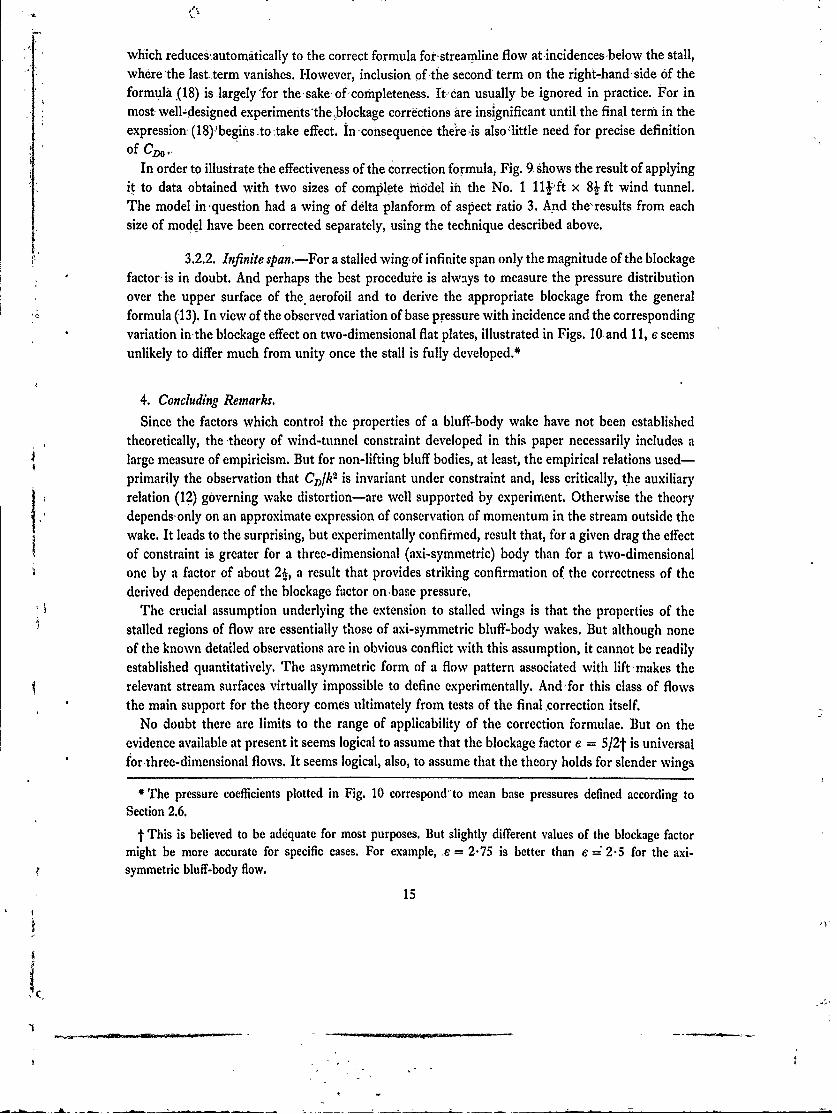
which reducesautomatically to the correct formula for-streamline flow at-incidences-below the stall,where 'the last.term vanishes. However, inclusion of the second term on the right-hand side of theformula (18) is largely'for thesake of-completeness. Itcan usually be ignored in practice. For inmost-well-designed experimefits'the blockage corrections are insignificant until, the final term in theexpression (18):begins to -take effect. In -consequence thereis also'little need for precise definitionof C.
In order to illustrate the effectiveness of the correction formula, Fig. 9 shows the result of applyingit to data obtained with two sizes of complete model in the No. 1 11-I t x 8 ft wind tunnel.The model -in 'question had a wing of delta planform of aspect ratio 3. And the'results from eachsize of model have been corrected separately, using the technique described above.
3.2.2. Infinite span.-For a stalled wing~of infinite span only the magnitude of the blockagefactor-is in doubt. And perhaps the best procedure is always to measure the pressure distribution
over the upper surface of the aerofoil and to derive the appropriate blockage from the general- -formula (13). In view of the observed variation of base pressure with incidence and the corresponding
variation in-the blockage effect on two-dimensional flat plates, illustrated in Figs. 10and 11, c seemsunlikely to differ much from unity once the stall is fully developed.*
4. Concluding Remarks.
Since the factors which control the properties of a bluff-body wake have not been establishedtheoretically, the -theory of wind-tunnel constraint developed in this paper necessarily includes alarge measure of empiricism. But for non-lifting bluff bodies, at least, the empirical relations used-primarily the observation that Cl)/k 2 is invariant under constraint and, less critically, the auxiliaryrelation (12) governing wake distortion-are well supported by experiment. Otherwise the theoryI dependsonly on an approximate expression of conservation of momentum in the stream outside thewake. It leads to the surprising, but experimentally confirmed, result that, for a given drag the effectof constraint is greater for a three-dimensional (axi-symmetrie) body than for a two-dimensionalone by a factor of about 2-, a result that provides striking confirmation of the correctness of thederived dependence of the blockage factor on~base pressure.
The crucial assumption underlying the extension to stalled wings is that the properties of thestalled regions of flow are essentially those of axi-symmetric bluff-body wakes. But although noneof the known detailed observations are in obvious conflict with this assumption, it cannot be readilyestablished quantitatively. The asymmetric form of a flow pattern associated with lift -makes therelevant stream surfaces virtually impossible to define experimentally. Andfor this class of flowsthe main support for the theory comes ultimately from tests of the final ,correction itself.
No doubt there are limits to the range of applicability of the correction formulae. But on theevidence available at present it seems logical to assume that the blockage factor e = 512t is universalfor-hree-dimensional flows. It seems logical, also, to assume that the theory holds for slender wings
* The pressure coefficients plotted in Fig. 10 correspond-to mean base pressures defined according toSection 2.6.
t This is believed to be adequate for most purposes. But slightly different values of the blockage factormight be more accurate for specific cases. For example, .e 2.75 is better than e = 2.5 for the axi-symmetric bluff-body flow.
15
tV

with vortex breakdoWn-which:gives rise to-axi-syiimetric regions cftflow resembling bluff-body
Wakes-provided-that the breakdown occurs sufficiently well forward of ,the trailing, edge. The'e
is little doubt that, in the absence of-vortex-breakdown, the flow past a slender,-winggr,.body is, for
the present purpose, a streamline flow, subject only to. the conventional wake-blockage correction.
In many ways the most difficult partof the stalled-wing problem is to identify the'induced drag
which, by subtraction from the measured drag, effectively defines the component-of drag associated
'with the blockage "effect. The 'empirical extrapolation proposed here is, at best, ;plausible. It is
believed to be-adequate, at least for a moderate range Of incidence beyondthe onset of stall, where
practical interest is greatest. But the theory should obviously be applied With judgement. And
experiments should be designed so as to make the correction small, and-thus to minimize the effects
of errors in.the empirical parameters that enter the correction formulae. It is also advisable to obtain
visual observations of the onset of stall.
1
16

SYMBOLS
x, y, 2 Rectangular Cartesian co-ordinates, with x measured in the direction ofthe .undisturbed stream
u, v, to Velocity component in the x, y and z directions,
U, P, H Velocity, static pressure and total head of the undisturbed stream
q Dynamic pressure of the undisturbed stream
p Static pressure
P Base pressure
Cx, Pressure coefficient (p- P)/q
D Drag
Do, D, Ds, DR Components of the measured drag (Section 3.2.1)
CI) Drag coefficient DlqS
h Base-pressure parameter (Section;2.1)
S Reference area of model
C Cross-sectional area of wind tunnel
-' B Cross-sectional area of wake
A Aspect ratio
i m BIS
m* A datum value of m (Sec, on 2.4)
6 Blockage factor (equatior, (14))
a Operator denoting increment due to constraint
C Suffix denoting effective, or corrected, values
17
(900) 17B
p
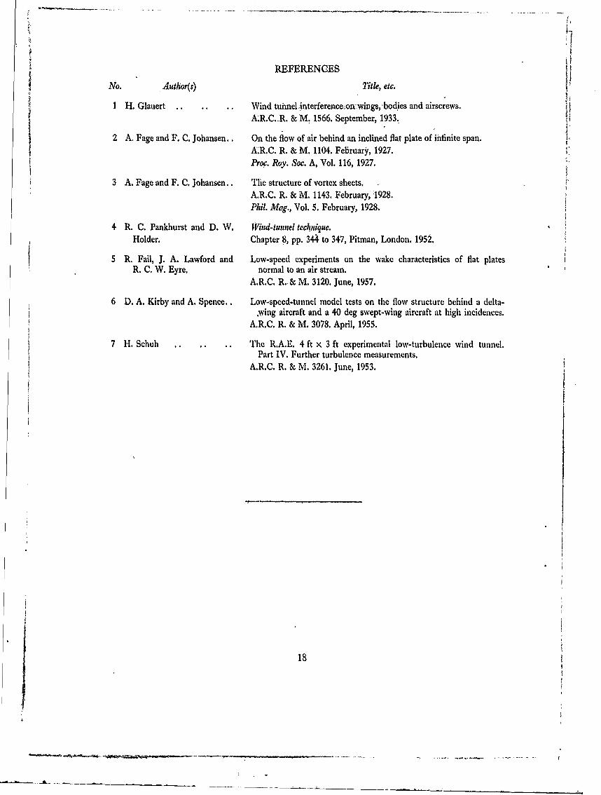
REFERENCES[i
No. Author(s) Title, etc.
I H. Glauert .. Wind tuimelinterferenceon.wings, bodies and airscrews.A.R.C.-R. & M. 1566. September, 1933.
2 A. Fage and F. C. Johansen.. On the flow of air behind an inclined flat plate of infinite span.AR.C. R. & M. 1104. February, 1927.Pro c. Roy. Soc. A, Vol. 116, 1927.
3 A. Fage and F. C. Johansen.. The structure of vortex sheets.A.R.C. R. & M. 1143. February, "1928.Phil. Mag., Vol. 5. February, 1928.
4 R. C. Pankhurst and D. W. Wind-tunnel technique.Holder. Chapter 8, pp. 344 to 347, Pitman, London. 1952.
5 R. Fail, J. A. Lawford and Low-speed experiments on the wake characteristics of flat platesR. C. W. Eyre. normal to an air stream.
A.R.C. R.-& M. 3120. June, 1957.
6 D. A. Kirby and A. Spence.. Low-speed-tunnel model tests on the flow structure behind a delta-.wing aircraft and a 40 deg swept-wing aircraft at high incidences.
A.RC. R. & M. 3078. April, 1955.
7 H. Schuh .. .. .. The R.A.E. 4 ft x 3 ft experimental low-turbulence wind tunnel.Part IV. Further turbulence measurements.
A.R.C. R. & M. 3261. June, 1953.
18

' I
S -
Fci
* L
19
---- -- o -
*00o u
4
I~ I I,-0 -
4. 00~ x.I u6-
0.0
.01
20)
0 U
0i0.u
00
1.0
ti t -oo
00
21 ~
-1o
z.o _ _ 1_ 0Wz-) t o u
0~
Id 1C9d 4~0i. OLo **o of Ab0
00
cl O.
0u cu 7 0 06dg
22(90995) Vt. 66,(2301 K(.5 2/65 11w.

m ;2 0 Z C
0 Ln r 00- -0cu-' >
='- tvmzCl *,a 1:-
Z oCo a o
0..- t= j
0Z4 004
11'* a(U R c
cQ 0 -tp
~ 4W4
W4 Q
0bU ar E L4
z = "
,< 4 WEE r-.4
%d in 0 ... eZ w ~ :6EC dL
An IT. :5 ; U mz .
-4r
- it2~U rncc -'~ . ~ - E4 .( 0
o o & z- I .4
u = 6. 4. o' Sr r4 4
, M-1 00 .00
b.Ii
____ ____ ____ ____ ____
~-----------s~--..------ -.- Q 4----~---
a -~~~~~~ -i------ o-. -

AA
4) 4)
4) Q.
2 41
to 0cd
-.2
0.
60, 10, oi WO oi O
004~a
o.e4 *4
-0~
Cuu
4 o
-0.4)0 V,.40
0 .
0.
'Co 0. ) Cu 0

f -i
.4, 4',
A r4 '4 T5~ I, vi' It e,4.
* - ', sa v t. ' r I tait ' l's d.1''- Tuou.. tr ~tos -:. ~ 11, 3d')
L,' A in5i'7 A "
2' 5 , -, 5 -- I IN 4.t: 25Ars~~~ -r 24 t, IN s .sl, l2 ~ - .'5 Ytv;!e , I r'.4-t'4 2.-,4
-v,, r1
.. d 2,(p.i .- S) .544 ,AHs Pm c . -'os v".I35
* -. . \4i~f~i50.#, 154, ''' .l.,C IS'' ~ .,....., .4 - .. i'lzI! 4,, il:5..s4.,if 1I544
15'pt 'in ~y sL r- . Istil ',* -: iit ,r;,WNO ass o ~o> 3.jt
71,s Nps-- J. j-d
* ! ~"~ ,s.4lld.'y-v'i, :r",. -''Al 10 N IXrrh !Ic EN'r.l4 UA'Ld- 22. , 5 sP.'4554I 4',55u 4'
7s'i5C. '.. 557. 0 1-C"
sts. 'd 'r- 5-'s~,,.\i.'-P, \I-,v'-',Itslc~- 4~'zr !ss-, o 4 -. s;'.l- 444;.
I~'i~i-d~s $, BEIcr'S T i.45.y St,'iS','tr 2itpsr2 ~ i..~
1k ~ ~ VAU L 4.A- f xArsattcdi.-COPY.h(Tuni

~QCrmm n ~pyrcght t965
Printed and p,.blishcJ byfliRR MAJE~STY'%S TATIONER~Y OFEICSi
To be p-urchased frOznYork Flou-sc. Kingsway, London w.c.2
4Z3 Oxf.rd Stniet, London w. x13A Catic Street, Edinburgh z
109 St. Mary Street, Cardiff3o King Stretet, Manjchesiter 2
50 i.'.tirfax Stienr, Bristol t3S Smallbrock, Ringwiny, Birminghamz 5
8o Chichester Strter-, Belfast ior thruugh any ibkoller
ih nt i1e E'ngland