Maserati M145 TPMS Functional Specification - V1_04
7
Maserati M145 TPMS Functional Specification Maserati M145 TPMS Functional Specification - V1_04.doc 1_04 Page 1 of 7 RD096 071112 Maserati M145 TPMS Functional Specification 1 Modifications Approved Date Modifications Author Version Modified Sheets By Date Signed 03/01/2010 Document creation JRS 1_01 All 19/01/2010 Document updated JRS 1_02 All 28/01/2010 The implicit and derived requirements are mentioned SJ 1_03 All 09/02/2010 Reset condition when pressure goes below 0.6 bar described SJ 1_04 All JRS 11/02/2010 JRS
Transcript of Maserati M145 TPMS Functional Specification - V1_04

Maserati M145 TPMS Functional Specification
Maserati M145 TPMS Functional Specification - V1_04.doc
1_04 Page 1 of 7
RD096 071112
Maserati M145 TPMS Functional Specification 1 Modifications
Approved Date Modifications Author Version Modified Sheets By Date Signed
03/01/2010 Document creation JRS 1_01 All 19/01/2010 Document updated JRS 1_02 All
28/01/2010 The implicit and
derived requirements are mentioned
SJ 1_03 All
09/02/2010 Reset condition when pressure goes below
0.6 bar described SJ 1_04 All JRS 11/02/2010 JRS
Maserati M145 TPMS Functional Specification
Maserati M145 TPMS Functional Specification - V1_04.doc
1_04 Page 2 of 7
RD096 071112
1 Modifications..........................................................................................................................................................................1 2 Introduction ............................................................................................................................................................................3 3 CAN Specification .................................................................................................................................................................4
3.1 Tx....................................................................................................................................................................................4 3.1.1 Notes......................................................................................................................................................................4
3.2 Rx...................................................................................................................................................................................5 3.3 ECU – PC Development Software CAN Communications.........................................................................................5
4 TPMS Behaviour ...................................................................................................................................................................6 4.1 Hardware Faults ............................................................................................................................................................6 4.2 Tyre Warnings ...............................................................................................................................................................6
4.2.1 Nominal Pressure Setting .....................................................................................................................................6 4.2.2 Soft Warning ..........................................................................................................................................................7
4.2.2.1 Reset Condition .............................................................................................................................................7 4.2.3 Hard Warning.........................................................................................................................................................7
4.2.3.1 Reset Condition .............................................................................................................................................7 4.2.4 Rapid Pressure Loss.............................................................................................................................................7
4.2.4.1 Reset Condition .............................................................................................................................................7 4.2.5 Run Flat Warning...................................................................................................................................................7
4.2.5.1 Reset Condition .............................................................................................................................................7 4.2.6 Over Temperature Warning..................................................................................................................................7
4.2.6.1 Reset Condition .............................................................................................................................................7 4.3 Wheel Position Changing .............................................................................................................................................7

Maserati M145 TPMS Functional Specification
Maserati M145 TPMS Functional Specification - V1_04.doc
1_04 Page 3 of 7
RD096 071112
2 Introduction Maserati require a Tyre Pressure Monitoring System (TPMS) which utilises two DGA+ antennae to receive datagrams transmitted by the wheel sensors. BERU f1systems are to supply the ECU which is capable of fulfilling this task. The TPMS ECU is to be a direct replacement for the current BERU Gen2 TPMS ECU. Therefore it must utilise the existing CAN specification. The TPMS will have to implement the following features:
• Rx and Tx of CAN messages on the 50kbaud Low Speed CAN bus
• Diagnostics (KWP2000) on the 50kbaud Low Speed CAN bus
• Network Management on the 50kbaud Low Speed CAN bus The basis for the new TPMS ECU firmware is the Ferrari F430 LP software (F1-37-2219-G).

Maserati M145 TPMS Functional Specification
Maserati M145 TPMS Functional Specification - V1_04.doc
1_04 Page 4 of 7
RD096 071112
3 CAN Specification 3.1 Tx The TPMS ECU is required to transmit a single CAN message. The specification for this can be found below:
ID ID Name Rate Dir DLC Byte Bit Signal Name Signal Function Range Scaling Resolution Notes
0x3DC Status_NTP 500ms Tx 8 0 0 TyrePressureSystemSts
TPMS Status 0-1 0x0 = On 0x1 = Disabled
Note: Always On
0 1 TyrePressureSystemFailSts
TPMS Failure Status
0-1 0x0 = Fail Not Present 0x1 = Failt Present
0 2 TyrePressureSy
sCalibrationSts
TPMS Calibration
Status
0-1 0x0 = System
Calibrated 0x1 = System Not Calibrated
0 3 NTPTempNotActiveSts
TPMS Temporarily Not Active
0-1 0x0 = Active 0x1 = Temporarily Not Active
Note: Always returns active
0 4 NTPCalibrationReqACK
TPMS Calibration Acknowledgement
0-1 0x0 = No Calibration Request
0x1 = Calibration Request
Acknowledgement
0 5 Unused Unused
0 6-7 IDTyre_temperature
Index For Tyre Temperature
0-3 0x0 = FL 0x1 = FR
0x2 = RL 0x3 = RR
1 0-7 TemperatureSts_xx
Tyre Temperature -40 – +215°C
X-40 1°C 0x0 = Startup Default 0xFE = Value Not Available
0xFF = Fault Present
2 0-1 UnknownTyrePr
essureSts
Spare Wheel
Status
0-3 Not used in this
application
2 2-5 Unused Unused
2 6-7 TPMSTelltaleSts TPMS Lamp Status 0-3 0x0 = Lamp Off 0x1 = Lamp Flashing
0x2 = Lamp On 0x3 = Unused
3 0-1 RHRTyrePressureSts
RR Tyre Pressure Status
0-3 0x0 = Tyre Ok 0x1 = Soft Warning 0x2 = Hard Warning 0x3 = Tyre Over Temp.
3 2-3 LHRTyrePressureSts
RL Tyre Pressure Status
0-3 0x0 = Tyre Ok 0x1 = Soft Warning 0x2 = Hard Warning
0x3 = Tyre Over Temp.
3 4-5 RHFTyrePressureSts
FR Tyre Pressure Status
0-3 0x0 = Tyre Ok 0x1 = Soft Warning 0x2 = Hard Warning
0x3 = Tyre Over Temp.
3 6-7 LHFTyrePressureSts
FL Tyre Pressure Status
0-3 0x0 = Tyre Ok 0x1 = Soft Warning 0x2 = Hard Warning 0x3 = Tyre Over Temp.
4 0-7 LHFPressureSts FL Gauge Tyre Pressure
0-5.375 0.025bar/bit 0xFE = Value Not Available 0xFF = Fault Value
5 0-7 RHFPressureSts FR Gauge Tyre Pressure
0-5.375 0.025bar/bit 0xFE = Value Not Available 0xFF = Fault Value
6 0-7 LHRPressureSts RL Gauge Tyre
Pressure
0-5.375 0.025bar/bit 0xFE = Value Not
Available 0xFF = Fault Value
7 0-7 RHRPressureSts
RR Gauge Tyre Pressure
0-5.375 0.025bar/bit 0xFE = Value Not Available 0xFF = Fault Value
3.1.1 Notes In this application the signal TyrePressureSystemSts is always set to 0x0 because the TPMS is always active. In this TPMS implementation the signal NTPTempNotActiveSts is always set to 0x0.
Maserati M145 TPMS Functional Specification
Maserati M145 TPMS Functional Specification - V1_04.doc
1_04 Page 5 of 7
RD096 071112
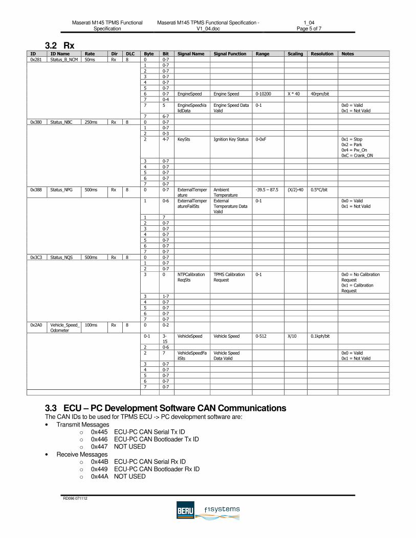
3.2 Rx ID ID Name Rate Dir DLC Byte Bit Signal Name Signal Function Range Scaling Resolution Notes
0x281 Status_B_NCM 50ms Rx 8 0 0-7
1 0-7
2 0-7
3 0-7
4 0-7
5 0-7
6 0-7 EngineSpeed Engine Speed 0-10200 X * 40 40rpm/bit
7 0-4
7 5 EngineSpeedVa
lidData
Engine Speed Data
Valid
0-1 0x0 = Valid
0x1 = Not Valid
7 6-7
0x380 Status_NBC 250ms Rx 8 0 0-7
1 0-7
2 0-3
2 4-7 KeySts Ignition Key Status 0-0xF 0x1 = Stop 0x2 = Park 0x4 = Pw_On
0xC = Crank_ON
3 0-7
4 0-7
5 0-7
6 0-7
7 0-7
0x388 Status_NPG 500ms Rx 8 0 0-7 ExternalTemperature
Ambient Temperature
-39.5 – 87.5 (X/2)-40 0.5°C/bit
1 0-6 ExternalTemper
atureFailSts
External
Temperature Data Valid
0-1 0x0 = Valid
0x1 = Not Valid
1 7
2 0-7
3 0-7
4 0-7
5 0-7
6 0-7
7 0-7
0x3C3 Status_NQS 500ms Rx 8 0 0-7
1 0-7
2 0-7
3 0 NTPCalibration
ReqSts
TPMS Calibration
Request
0-1 0x0 = No Calibration
Request 0x1 = Calibration
Request
3 1-7
4 0-7
5 0-7
6 0-7
7 0-7
0x2A0 Vehicle_Speed_ Odometer
100ms Rx 8 0 0-2
0-1 3-15
VehicleSpeed Vehicle Speed 0-512 X/10 0.1kph/bit
2 0-6
2 7 VehicleSpeedFailSts
Vehicle Speed Data Valid
0x0 = Valid 0x1 = Not Valid
3 0-7
4 0-7
5 0-7
6 0-7
7 0-7
3.3 ECU – PC Development Software CAN Communications The CAN IDs to be used for TPMS ECU -> PC development software are:
• Transmit Messages o 0x445 ECU-PC CAN Serial Tx ID o 0x446 ECU-PC CAN Bootloader Tx ID o 0x447 NOT USED
• Receive Messages o 0x44B ECU-PC CAN Serial Rx ID o 0x449 ECU-PC CAN Bootloader Rx ID o 0x44A NOT USED

Maserati M145 TPMS Functional Specification
Maserati M145 TPMS Functional Specification - V1_04.doc
1_04 Page 6 of 7
RD096 071112
4 TPMS Behaviour 4.1 Hardware Faults If the TPMS suffers a hardware fault, it will set the signal TyrePressureSystemFailSts to 0x1, and will set the signal TPMSTelltaleSts to 0x1 for a period of 85 seconds, after which it will set the value to 0x2. Calibration is not allowed. Calib_Ack is held at 0. On all further ignition cycles, the signal TPMSTelltaleSts will be set to 0x1 for 85 seconds, and then changed to 0x2 if the hardware fault is still present. A list of hardware faults which can be identified by the system can be found in the diagnostics specification.
4.2 Tyre Warnings 4.2.1 Nominal Pressure Setting The TPMS for the M145 has a fundamental difference in its behaviour, when compared to other BERU f1systems TPMS implementations. The TPMS does not utilise traditional speed versus pressure maps, and instead uses a set of nominal pressure values (one for each wheel) to calculate the warning pressure limits. The TPMS sets the nominal pressure values when a calibration is requested (NTPCalibrationReqSts signal in STATUS_NQS CAN message). The procedure for conducting a calibration is:
1. Once the calibration has been requested, by the NTPCalibrationReqSts signal being set equal to 0x1, the TPMS sets the signal NTPCalibrationReqACK to 0x1.
2. If the system has received a full set of wheel sensors on that ignition cycle and all the pressures are above 0.6bar gauge, then the system takes the highest pressure from each axle, (aka the nominal pressure) and computes the soft and hard warning pressure limit for each axle using the following algorithms:
a. Soft warning limits = nominal pressure – 0.3bar b. Hard warning limits = 75% of the nominal pressure(Remember that absolute pressure is taken into
account for setting the soft and hard warning limits and not gauge pressure). The pressure values shown in the pressure map indicate only the right tyre values for both front and rear. For testing, the actual pressure values should be noted down at the time of requesting nominal pressure setting.
The soft and hard warning limits should then be written into pressure map 1 of the TPMS ECU. This is the only pressure map that will be used by the TPMS in this application. Once the system has finished writing the values into the pressure map (i.e. has successfully completed its calibration correctly), and only if a time period greater than or equal to five seconds since the calibration was requested, the value of TyrePressureSysCalibrationSts should be set to 0x0 and the value of NTPCalibrationReqACK should be set to 0x0. If the time period since the calibration was requested is less than five seconds, the values of TyrePressureSysCalibrationSts and NTCalibrationReqACK should be held until five seconds has elapsed, and then changed.
3. If the system has not received a full set of wheel sensors, the TPMS should pause its calibration until it has received a full set of wheel sensors. As soon as it has received a full set of sensors, it should complete its calibration. If the vehicle is driven and a full set of sensors are not received, then the system will activate the warning for a sensor timeout. If this happens before a calibration is completed, then the value of the signal NTPCalibrationReqACK should be set to 0x0, the value of TyrePressureSysCalibrationSts should be left unmodified, TyrePressureSystemFailSts should be set to 0x1, and TPMSTelltaleSts should be set to 0x1 for a period of 85 seconds, after which it will set the value to 0x2. If this happens after a calibration is completed, then the value of the signal NTPCalibrationReqACK and TyrePressureSysCalibrationSts are left unmodified and TyrePressureSystemFailSts, TPMSTelltaleSts signals should be changed as described earlier.
4. If any of the tyre pressures are below 0.6bar gauge, then the value of the signal NTPCalibrationReqACK should be set to 0x0, the value of TyrePressureSysCalibrationSts should be set to 0x1, TyrePressureSystemFailSts should be set to 0x1, and TPMSTelltaleSts should be set to 0x2. Calibration is not allowed. As soon as the pressure goes above 0.6 bar, the above conditions are reverted.
5. Implicit Requirements: If driver presses the calibration button(NTPCalibrationReqSts signal being set equal to 0x1), system will be re-calibrated as long as pressure is above 0.6 bar irrespective of whether we are stationary or not. Only a pulse signal is expected for NTPCalibrationReqSts. If NTPCalibrationReqSts is held at 1, it is treated as a new request after every 5 seconds.

Maserati M145 TPMS Functional Specification
Maserati M145 TPMS Functional Specification - V1_04.doc
1_04 Page 7 of 7
RD096 071112
4.2.2 Soft Warning If any of the tyre pressures drop below the limits set for the soft warning, then a soft warning is activated. This is done by setting the value in the relevant XXXTyrePressureSts (where XXX is the wheel position) signal value to 0x1, and setting TPMSTelltaleSts to 0x2.
4.2.2.1 Reset Condition The soft warning is de-activated when a pressure is received from the wheel in question, which is greater than the soft warning limit.
4.2.3 Hard Warning If any of the tyre pressures drop below the limits set for the hard warning, then a hard warning is activated. This is done by setting the value in the relevant XXXTyrePressureSts (where XXX is the wheel position) signal value to 0x2, and setting TPMSTelltaleSts to 0x2.
4.2.3.1 Reset Condition The hard warning is de-activated when a pressure is received from the wheel in question which is greater than the hard warning limit.
4.2.4 Rapid Pressure Loss If a rapid pressure loss occurs (a rapid pressure loss is defined as a compensated pressure loss greater than or equal to 0.35bar/min), then a hard warning is activated. This is done by setting the value in the relevant XXXTyrePressureSts (where XXX is the wheel position) signal value to 0x2, and setting TPMSTelltaleSts to 0x2.
4.2.4.1 Reset Condition The rapid pressure loss warning is de-activated on the next ignition cycle when the conditions to activate this warning are no longer presetn
4.2.5 Run Flat Warning If any tyre pressure drops below 0.6bar gauge, then the tyre is defined as being in a run flat condition. This is to be signalled to the driver as a hard warning. This is done by setting the value in the relevant XXXTyrePressureSts (where XXX is the wheel position) signal value to 0x2, and setting TPMSTelltaleSts to 0x2.
4.2.5.1 Reset Condition The run flat warning is de-activated when a pressure is received from the wheel in question which is greater than the run flat warning limit.
4.2.6 Over Temperature Warning If any tyre temperature exceeds the maximum temperature limit (105°C), then the system will activate an over temperature warning. This is done by setting the value in the relevant XXXTyrePressureSts (where XXX is the wheel position) signal value to 0x3, and setting TPMSTelltaleSts to 0x2.
4.2.6.1 Reset Condition The over temperature warning is de-activated when a temperature of 100°C or less is received from the wheel in question.
4.3 Wheel Position Changing If the system detects that at least one wheel sensor position has changed since the last ignition cycle, then it is likely that the wheels have been changed and therefore the warning thresholds might not be appropriate any longer. This means that the TPMS should ask the driver to re-calibrate by activation of the push-button, which lets the TPMS re-calculate the warning thresholds. Therefore if the TPMS detects a change of wheel sensor IDs it should illuminate the TPMS warning lamp by setting TPMSTelltaleSts to 0x2, and setting TyrePressureSysCalibrationSts to 0x1. Once a calibration is requested by the driver, the system should respond according to the behaviour documented in Section 4.2.1.