Maruti Project
13
1 VOCATIONAL TRAINING REPORT MARUTI SUZUKI SERVICE CENTER SKY AUTOMOBILES RAIPUR Submitted by: College: Saket Tiwari NIT Raipur Ajay Agrawal Manish Dev
-
Upload
akash-jain -
Category
Documents
-
view
31 -
download
2
description
Overview
Transcript of Maruti Project

1
VOCATIONAL TRAINING REPORT
MARUTI SUZUKI SERVICE CENTER
SKY AUTOMOBILES
RAIPUR
Submitted by: College:
Saket Tiwari NIT Raipur
Ajay Agrawal
Manish Dev

2
ACKNOWLEDGEMENT
With profound respect and gratitude, I take opportunity to convey my thanks to HR
Department of Sky Automobiles for permitting me to complete my training in the Service
Centre and to be the part of this esteemed organization.
I‟m extremely grateful to all the technical staff of Sky Automobiles for their co-operation and
guidance that has helped me a lot during the course of training. I have learnt a lot under them
and I will always be indebted to them for this value addition in me.
At last I would like to convey my thanks to all the members of the workshop who have
helped me at every stage of training and I am are forever indebted to the omnipotent and to
my parents for their cheerful encouragement, unfailing patience and consistent support.

3
CONTENTS
1. INTRODUCTION
2. CHASSIS
3. FRAME INTEGRAL FRAME OR FRAME-LESS CONSTRUCTION
4. SUSPENSION SYSTEM FUNCTIONS OF SUSPENSION SYSTEM
LEAF SPRINGS
COIL SPRINGS
SUSPENSION TYPES – DEPENDENT HOTCHKISS DRIVE
INDEPENDENT
5. STEERING SYSTEM
6. TRANSMISSION
CLUTCH
PRINCIPLE OF CLUTCH
MAIN PARTS OF A CLUTCH
FUNCTION OF GEAR BOX
7. ANTI-LOCK BRAKING SYSTEM

4
INTRODUCTION The automobiles such as cars, buses and trucks, etc. are generally considered to be consisting
of two major assemblies, chassis and body.
Automobile repairing and servicing is a most commonly known activity in almost all
urban areas where all types of motor vehicles like cars, buses, lorries, jeeps, etc. are
given for service and repairs. Regular maintenance and servicing of vehicles is
required for safe driving and durability of the vehicles. Improper maintenance of vehicles,
present conditions of roads, irresponsible driving, using cheaper spare parts, etc. are the main
reasons to send the vehicles for repairs and maintenance. Service station is the most essential
unit to vehicle users. This unit can be established in urban, semi-urban and village are to meet
the local requirement. Candidates having good experience or qualified persons can start this
unit with low investment.
There is good demand for automobile service centre due to increase in the number of vehicles
day to day. After implementation of globalisation and privatisation, many Multi-national
companies competing with each other and introduced many models of4-wheelers and 2-
wheelers. Besides, the purchasing power of the people also increasing considerably and it
becomes fall under necessary item in the cities/urban areas especially for business persons
and salaried persons. Now a days, the middle class persons are also maintaining 4-
wheelers/2-wheelersdue to affordable price and changing habits of the consumers. Hence,
there is a good demand for setting up of automobile servicing and repairing units particularly
in some important tribal centres.
CHASSIS
Chassis is a French term which is now denotes the whole vehicle except body in case of
heavy vehicles. In case of light vehicles of mono construction, it denotes the whole vehicle
except additional fittings in the body.
“Chassis consists of engine, power train, brakes, steering system and wheels mounted on a
frame”.
FRAME
The frame is the main part of the chassis on which remaining parts of chassis are mounted.
The frame should be extremely rigid and strong so that it can withstand shocks, twists,
stresses and vibrations to which it is subjected while vehicle is moving on road. It is also
called underbody.
The frame is supported on the wheels and tyre assemblies. The frame is narrow in the front
for providing short turning radius to front wheels. It widens out at the rear side to provide
larger space in the body.

5
Integral Frame or Frame-less Construction
This frame is generally used in modern day automobiles including Maruti-Suzuki. In this type
of construction, there is no frame. It is also called unitized frame-body construction. In this
case, the body shell and underbody are welded into single unit. The underbody is made of
floor plates and channel and box sections welded into single unit. This assembly replaces the
frame. This decreases the overall weight compared to conventional separate frame and body
construction.
SUSPENSION SYSTEM
The frame and body of an automobile are mounted on front and rear axles through springs
and shock absorbers. If it is mounted directly on axles, all the socks and vibrations will be
transmitted to body causing discomfort to the passengers. The springs and shock absorbers
are used to damp the shocks and vibrations. The suspensions system includes all those parts
which are used to perform the damping action. Besides, springs and shock absorbers, a
suspension system includes other mountings also. The suspension system of a vehicle is
divided into front suspension and rear suspension.
FUNCTIONS OF SUSPENSION SYSTEM
(a) The main function of a suspension system is to prevent the socks to transmit to car or
vehicle body so that passengers may ride comfortably.
(b) To maintain the stability of vehicle during pitching and rolling actions while the vehicle is
in motion.
(c) To provide better road holding at the time of driving, braking and cornering.
(d) To allow proper steering geometry.
LEAF SPRINGS
Leaf Springs are used in rear suspensions in vehicles such as Maruti-Suzuki Omini and Eeco.
These springs are made by placing several flat strips one over the other. These are made of
steel plates. One flat strip is called a leaf. Lowest leaf is of smallest length and the length of
other leaves placed above this keeps on increasing progressively. In this way, the length of
top most leaf (main leaf) largest. Main leaf has eyes at the ends. All the leaves are clamped

6
together at centre and sides by the centre bolt and side clamps respectively. The centre
portion of the leaf springs is connected to the axle with the help of U-bolt.
COIL SPRINGS
Coil springs are in the form of helix. These are made from special steel. It is made from steel
wire in the form of a coil. The coil springs absorb energy when this spring is compressed
while vehicle moves over road bump. The coil springs are mainly used in independent
suspension. However, these can also be used in the conventional rigid axle suspension. Coil
springs are capable of resisting shear and bending stresses but not torsion and side thrust.
When coil springs are used in the suspension system, other arrangements are made to bear
torsion and side thrust.
Advantages of Coil Springs
(a) Coil springs are better than leaf springs as they can absorb almost double energy per unit
volume as compared to leaf springs.
(b) They also require less space than leaf springs and can be used in very restricted spaces.
(c) Coil springs are lighter in weight for the same load.
(d) Compact in size.
Suspension Types -Dependent
Motion of a wheel on one side of the vehicle is dependent on the motion of its partner
on the other side
Rarely used in modern passenger cars
Can not give good ride
Cannot control high braking and accelerating torques
Used in commercial and off-highway vehicles
Hotchkiss Drive
•Axle is mounted on longitudinal leaf springs, which are compliant vertically and stiff
horizontally
•The springs are pin-connected to the chassis at one end and to a pivoted link at the other.
•This enables the change of length of the spring to be accommodated due to loading

7
Fig 1 : Hotchkiss drive Fig 2 : Suspension in Maruti-Suzuki Omini
Suspension Types - Independent
•Motion of wheel pairs is independent, so that a disturbance at one wheel is not directly
transmitted to its partner
•Better ride and handling
Fig 3 : Macpherson Strut Fig 4 : Macpherson strut
Fig 5 : Trailing arm Fig 6 : Multi link
8
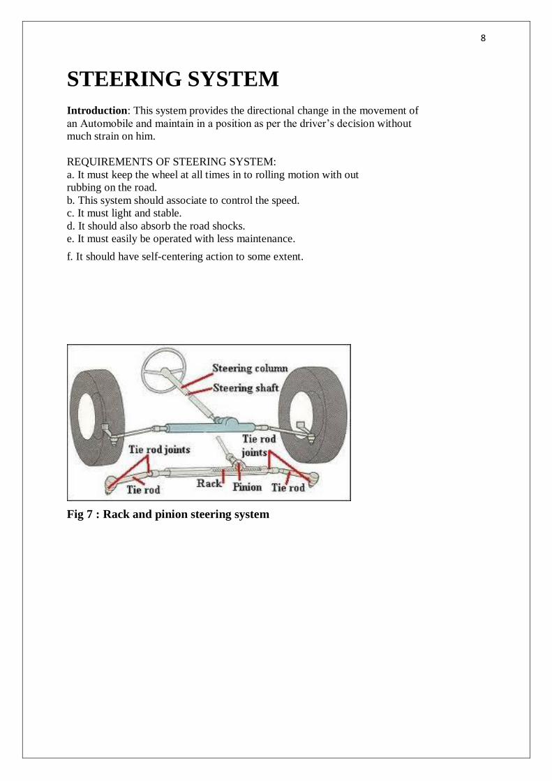
STEERING SYSTEM
Introduction: This system provides the directional change in the movement of
an Automobile and maintain in a position as per the driver‟s decision without
much strain on him.
REQUIREMENTS OF STEERING SYSTEM:
a. It must keep the wheel at all times in to rolling motion with out
rubbing on the road.
b. This system should associate to control the speed.
c. It must light and stable.
d. It should also absorb the road shocks.
e. It must easily be operated with less maintenance.
f. It should have self-centering action to some extent.
Fig 7 : Rack and pinion steering system

9
TRANSMISSION
Transmission is the mechanism which is used to transfer the power developed by engine to
the wheels of an automobile. The transmission system of an automobile includes clutch, gear
box, propeller shaft axle and wheels, etc. The term „Transmission‟ is used for a device which
is located between clutch and propeller shaft. It may be a gear box, an over drive or a torque
converter, etc.
CLUTCH
Clutch is used to engage or disengage the engine to the transmission or gear box. When the
clutch is in engaged position, the engine power or rotary motion of engine crankshaft is
transmitted to gear box and then to wheels. When clutch is disengaged, the engine power
does not reach to gear box (and to wheels) although engine is running.
Clutch is also used to allow shifting or changing of gears when vehicle is running. For
shifting gears, clutch is first disengaged then gear is shifted and then clutch is engaged.
Clutch has to be disengaged to stop the vehicle and also at the time of idling.
PRINCIPLE OF CLUTCH
It operates on the principle of friction. When two surfaces are brought in contact and are held
against each other due to friction between them, they can be used to transmit power. If one is
rotated, then other also rotates. One surface is connected to engine and other to the
transmission system of automobile. Thus, clutch is nothing but a combination of two friction
surfaces.
MAIN PARTS OF A CLUTCH
It consists of
(a) a driving member,
(b) a driven member, and
(c) an operating member.
Driving member has a flywheel which is mounted on the engine crankshaft. A disc is bolted
to flywheel which is known as pressure plate or driving disc.
The driven member is a disc called clutch plate. This plate can slide freely to and fro on the
clutch shaft.
The operating member consists of a pedal or lever which can be pressed to disengaged the
driving and driven plate.

10
FUNCTION OF GEAR BOX
An automobile is able to provide varying speed and torque through its gear box. Various
functions of a gear box are listed below :
(a) To provide high torque at the time of starting, vehicle acceleration, climbing up a hill.
(b) To provide more than forward speeds by providing more than one gear ratios. In modern
cars, five forward gears and reverse gear is provided. For given engine speed, higher speed
can be obtained by running in higher (4th and 5th) gears.
(c) Gear box provides a reverse gear for driving the vehicle in reverse direction.
Fig 8 : Gearbox of Maruti-Suzuki Swift

11
ANTI-LOCK BRAKING SYSTEM
Anti-lock braking system (ABS) is an automobile safety system that allows the wheels on
a motor vehicle to maintain tractive contact with the road surface according to driver inputs
while braking, preventing the wheels from locking up (ceasing rotation) and avoiding
uncontrolled skidding. It is an automated system that uses the principles of threshold
braking and cadence braking which were practiced by skillful drivers with previous
generation braking systems. It does this at a much faster rate and with better control than a
driver could manage. ABS generally offers improved vehicle control and decreases stopping distances on dry and
slippery surfaces for many drivers; however, on loose surfaces like gravel or snow-covered
pavement, ABS can significantly increase braking distance, although still improving vehicle
control.
Typically ABS includes a central electronic control unit (ECU), four wheel speed sensors,
and at least two hydraulic valves within the brake hydraulics. The ECU constantly monitors
the rotational speed of each wheel; if it detects a wheel rotating significantly slower than the
others, a condition indicative of impending wheel lock, it actuates the valves to reduce
hydraulic pressure to the brake at the affected wheel, thus reducing the braking force on that
wheel; the wheel then turns faster. Conversely, if the ECU detects a wheel turning
significantly faster than the others, brake hydraulic pressure to the wheel is increased so the
braking force is reapplied, slowing down the wheel. This process is repeated continuously
and can be detected by the driver via brake pedal pulsation. Some anti-lock systems can apply
or release braking pressure 15 times per second. Because of this, the wheels of cars equipped
with ABS are practically impossible to lock even during panic braking in extreme conditions.
The ECU is programmed to disregard differences in wheel rotative speed below a critical
threshold, because when the car is turning, the two wheels towards the center of the curve
turn slower than the outer two. For this same reason, a differential is used in virtually all
roadgoing vehicles.
If a fault develops in any part of the ABS, a warning light will usually be illuminated on the
vehicle instrument panel, and the ABS will be disabled until the fault is rectified.
Modern ABS applies individual brake pressure to all four wheels through a control system of
hub-mounted sensors and a dedicated micro-controller. ABS is offered or comes standard on
most road vehicles produced today and is the foundation for electronic stability control
systems, which are rapidly increasing in popularity due to the vast reduction in price of
vehicle electronics over the years.
Modern electronic stability control systems are an evolution of the ABS concept. Here, a
minimum of two additional sensors are added to help the system work: these are a steering
wheel angle sensor, and a gyroscopic sensor. The theory of operation is simple: when the
gyroscopic sensor detects that the direction taken by the car does not coincide with what the
steering wheel sensor reports, the ESC software will brake the necessary individual wheel(s)
(up to three with the most sophisticated systems), so that the vehicle goes the way the driver

12
intends. The steering wheel sensor also helps in the operation of Cornering Brake
Control (CBC), since this will tell the ABS that wheels on the inside of the curve should
brake more than wheels on the outside, and by how much.
ABS equipment may also be used to implement a traction control system (TCS) on
acceleration of the vehicle. If, when accelerating, the tire loses traction, the ABS controller
can detect the situation and take suitable action so that traction is regained. More
sophisticated versions of this can also control throttle levels and brakes simultaneously.
Upon the introduction of the Subaru Legacy in 1989, Subaru networked the four channel anti-
lock brake function with the all wheel drive system so that if the car detected any wheel
beginning to lock up, the variable assists the all wheel drive system installed on vehicles with
the automatic transmission would engage to ensure all wheels were actively gripping while
the anti-lock system was attempting to stop the car.
Fig 9 : Anti-lock Braking System Fig 10 : ABS of Maruti-Suzuki Swift
Speed sensors
The anti-lock braking system needs some way of knowing when a wheel is about to lock up.
The speed sensors, which are located at each wheel, or in some cases in the differential,
provide this information.
Valves
There is a valve in the brake line of each brake controlled by the ABS. On some systems, the
valve has three positions:
In position one, the valve is open; pressure from the master cylinder is passed right
through to the brake.
In position two, the valve blocks the line, isolating that brake from the master
cylinder. This prevents the pressure from rising further should the driver push the
brake pedal harder.
In position three, the valve releases some of the pressure from the brake.
Pump

13
When the ABS system operates the brake lines lose pressure. The pump re-pressurizes the
system.
Controller
The controller is an ECU type unit in the car which receives information from each individual
wheel speed sensor, in turn if a wheel loses traction the signal is sent to the controller, the
controller will then limit the brakeforce (EBD) and activate the ABS modulator which
actuates the braking valves on and off.
REFERENCES
Sky Automobiles for pictues namely fig 2, fig 4, fig 8 and fig 10.
The Automobile Journal of India for information on ABS.
Wikipedia for other pictures.