Martin Tracker Reversing - martin-eng-mx.com · Operator’s Manual M3446 Go to Martin ... Martin®...
42
Martin ® Tracker ™ Reversing Operator’s Manual M3446 Go to Martin ® Tracker™ Reversing web page
-
Upload
truongxuyen -
Category
Documents
-
view
226 -
download
0
Transcript of Martin Tracker Reversing - martin-eng-mx.com · Operator’s Manual M3446 Go to Martin ... Martin®...

Martin® Tracker™ Reversing
Operator’s Manual M3446
Go to Martin® Tracker™ Reversing web page

ImportantMARTIN ENGINEERING HEREBY DISCLAIMS ANY LIABILITY FOR: DAMAGE DUE TO CONTAMINATION OF THE MATERIAL; USER’S FAILURE TO INSPECT, MAINTAIN AND TAKE REASONABLE CARE OF THE EQUIPMENT; INJURIES OR DAMAGE RESULTING FROM USE OR APPLICATION OF THIS PRODUCT CONTRARY TO INSTRUCTIONS AND SPECIFICATIONS CONTAINED HEREIN. MARTIN ENGINEERING’S LIABILITY SHALL BE LIMITED TO REPAIR OR REPLACEMENT OF EQUIPMENT SHOWN TO BE DEFECTIVE.Observe all safety rules given herein along with owner and Government standards and regulations. Know and understand lockout/tagout procedures as defined by American National Standards Institute (ANSI) z244.1-1982, American National Standard for Personnel Protection - Lockout/Tagout of Energy Sources - Minimum Safety Requirements and Occupational Safety and Health Administration (OSHA) Federal Register, Part IV, 29 CFR Part 1910, Control of Hazardous Energy Source (Lockout/Tagout); Final Rule.
The following symbols may be used in this manual:
DANGER!
Danger: Immediate hazards that will result in severe personal injury or death.
WARNING!
Warning: Hazards or unsafe practices that could result in personal injury.
CAUTION!
Caution: Hazards or unsafe practices that could result in product or property damages.
IMPORTANTImportant: Instructions that must be followed to ensure proper installation/operation of equipment.
NOTENote: General statements to assist the reader.

Martin Engineering M3446-06/14 i Martin® Tracker™ Reversing
Table of Contents
Section PageList of Figures . . . . . . . . . . . . . . . . . . . . . . . . . . . . . . . . . . . . . . . . . . . . . . . . . . . . . . . . . . . . ii
Introduction . . . . . . . . . . . . . . . . . . . . . . . . . . . . . . . . . . . . . . . . . . . . . . . . . . . . . . . . . . . . . . 1General . . . . . . . . . . . . . . . . . . . . . . . . . . . . . . . . . . . . . . . . . . . . . . . . . . . . . . . . . . . . . . . . . . . . . . 1
References . . . . . . . . . . . . . . . . . . . . . . . . . . . . . . . . . . . . . . . . . . . . . . . . . . . . . . . . . . . . . . . . . . . 1
Safety . . . . . . . . . . . . . . . . . . . . . . . . . . . . . . . . . . . . . . . . . . . . . . . . . . . . . . . . . . . . . . . . . . . . . . . 1
Materials required . . . . . . . . . . . . . . . . . . . . . . . . . . . . . . . . . . . . . . . . . . . . . . . . . . . . . . . . . . . . . 1
Before Installing Belt Tracking System. . . . . . . . . . . . . . . . . . . . . . . . . . . . . . . . . . . . . . . . . 2
Installing Belt Tracking System. . . . . . . . . . . . . . . . . . . . . . . . . . . . . . . . . . . . . . . . . . . . . . . 3Installing lower guide unit . . . . . . . . . . . . . . . . . . . . . . . . . . . . . . . . . . . . . . . . . . . . . . . . . . . . . . . 3
Installing air cylinder controls . . . . . . . . . . . . . . . . . . . . . . . . . . . . . . . . . . . . . . . . . . . . . . . . . . . . 10
Installing upper guide unit . . . . . . . . . . . . . . . . . . . . . . . . . . . . . . . . . . . . . . . . . . . . . . . . . . . . . . . 12
After Installing Belt Tracking System . . . . . . . . . . . . . . . . . . . . . . . . . . . . . . . . . . . . . . . . . . 19
Part Numbers . . . . . . . . . . . . . . . . . . . . . . . . . . . . . . . . . . . . . . . . . . . . . . . . . . . . . . . . . . . . . 23
Appendix. Martin® Tracker™ Reversing Dimensions . . . . . . . . . . . . . . . . . . . . . . . . . . . . . A-1
Tab
le o
f C
onte
nts

Martin Engineering M3446-06/14 ii Martin® Tracker™ Reversing
List of Figures
Figure Title Page1 - 7 Installation Diagrams for Lower Guide Unit . . . . . . . . . . . . . . . . . . . . . . . . 3 - 9
8 Air Cylinder Controls . . . . . . . . . . . . . . . . . . . . . . . . . . . . . . . . . . . . . . . . . . 10
9 Air Cylinder Switching Mechanism . . . . . . . . . . . . . . . . . . . . . . . . . . . . . . . 11
10 - 16 Installation Diagrams for Upper Guide Unit . . . . . . . . . . . . . . . . . . . . . . . . 12 - 18
17 Adjusting Wheel on Switching Mechanism . . . . . . . . . . . . . . . . . . . . . . . . . 19
18 Adjusting Martin® Tracker™ Reversing . . . . . . . . . . . . . . . . . . . . . . . . . . . 21
19 Martin® Tracker™ Reversing (Lower Unit), P/N 34694-LXR. . . . . . . . . . . 24,25
20 Martin® Tracker™ Reversing (Lower Unit), P/N 34694-LXRA . . . . . . . . . 26,27
21 Martin® Tracker™ Reversing (Upper Unit), P/N 34695-UXR. . . . . . . . . . . 28,29
22 Martin® Tracker™ Reversing Cylinder Control Assembly, P/N 39292-XXX . . . . . . . . . . . . . . . . . . . . . . . . . . . . . . . . . . . . . . . . . . . . . . 30,31
23 Conveyor Products Warning Label, P/N 23395 . . . . . . . . . . . . . . . . . . . . . . 32
24 Pinch Point Label, P/N 30528. . . . . . . . . . . . . . . . . . . . . . . . . . . . . . . . . . . . 32
Lis
t of
Fig
ures
Martin Engineering M3446-06/14 1 Martin® Tracker™ Reversing
Introduction
General The Martin® Tracker™ Reversing automatically senses and continuously corrects belt tracking. A light touch of the belt against the guide rollers creates precision correction. The patented tie rod aligner translates the action of the steering bars to the training idlers. The switching mechanism senses the direction of the belt and mechanically engages the proper set of rollers to align reversing belts. The upper guide unit is used on the carrying side of the belt, and the lower guide unit is used on the return side.
References The following documents are referenced in this manual:
• American National Standards Institute (ANSI) z244.1-1982, American National Standard for Personnel Protection - Lockout/Tagout of Energy Sources - Minimum Safety Requirements, American National Standards Institute, Inc., 1430 Broadway, New York, NY 10018.
• Federal Register, Volume 54, Number 169, Part IV, 29 CFR Part 1910, Control of Hazardous Energy Source (Lockout/Tagout); Final Rule, Department of Labor, Occupational Safety and Health Administration (OSHA), 32nd Floor, Room 3244, 230 South Dearborn Street, Chicago, IL 60604.
Safety All safety rules defined in the above documents and all owner/employer safety rules must be strictly followed when working on this equipment.
Materials required Only standard hand tools are required to install and service this equipment.
Intr
oduc
tion

Martin Engineering M3446-06/14 2 Martin® Tracker™ Reversing
Before Installing Belt Tracking System
IMPORTANTThe delivery service is responsible for damage occurring in transit. Martin Engineering CANNOT enter claims for damages. Contact your transportation agent for more information.
1. Inspect shipping container for damage. Report damage to delivery service immediately and fill out delivery service’s claim form. Keep any damaged goods subject to examination.
2. Remove Martin® Tracker™ Reversing from shipping container. Equipment in container should include the following:
• Martin® Tracker™ Reversing (upper or lower guide unit).
• Two Conveyor Products Warning Labels, P/N 23395.
• Three Pinch Point Warning Labels, P/N 30528.
3. If anything is missing, contact Martin Engineering or a representative.
4. Make sure belt is centered on conveyor.
WARNING!
Before installing equipment, turn off and lock out/tag out energy source to conveyor and conveyor accessories.
5. Turn off and lock out/tag out energy source according to ANSI standards (see “References”).
WARNING!
If equipment will be installed in an enclosed area, gas level or dust content must be tested before using a cutting torch or welding. Using a cutting torch or welding in an area with gas or dust may cause an explosion.
6. If using a cutting torch or welding, test atmosphere for gas level or dust content. Cover conveyor belt with fire retardant cover.
Bef
ore
Inst
alla
tion

Martin Engineering M3446-06/14 3 Martin® Tracker™ Reversing
Installing Belt Tracking System
Installing lower guide unit
NOTEThe following installation procedures show the installation of
a Martin® Tracker™ Reversing with a standard switching mechanism. The Martin® Tracker™ Reversing is also
available with an air cylinder controlled switching mechanism.
1. Locate lower guide unit approximately three times the belt width before the point where belt adjustment is needed or before any major pulley. If installing multiple units, allow 70 to 150 ft. (21 to 50 m) between units depending on the severity of mistracking.
2. Remove existing return idler. Set aside for later use.
IMPORTANTFor belts 24 to 54 in. (600 to 1600 mm) wide, min. 17 in. (430 mm) clearance between belt line and any obstruction below is required. For belts 60 to 84 in. (1800 to 2400 mm) wide, min. 24 in. (610 mm) clearance between belt line and any obstruction below is required. Contact Martin Engineering for installation instructions for clearances less than those specified above.
3. Install lower guide unit as shown in Figures 1 through 7.
1.
24.75(629)
3-1/4(83)
IMPORTANT
3-1/4(83)
Inst
alla
tion

Martin Engineering M3446-06/14 4 Martin® Tracker™ Reversing
2.
CAUTION!
Failure to install bolts will causetorque arm assemblies to comeloose, causing damage tounit or conveyor belt.
Before installing bolts, applythread-sealing compound.
Standard switching mechanism shown.
Air cylinder controlled switching mechanism available.
See Figures 8 and 9 for air cylinder switching mechanism
installation orientation.
NOTE
Inst
alla
tion

Martin Engineering M3446-06/14 5 Martin® Tracker™ Reversing
3.
IMPORTANTAdjust channel brackets so return idler firmlycontacts belt. Fine tune position of unit bysliding it up or down before tightening hardware.
X
X
Y
Y
Inst
alla
tion
Martin Engineering M3446-06/14 6 Martin® Tracker™ Reversing
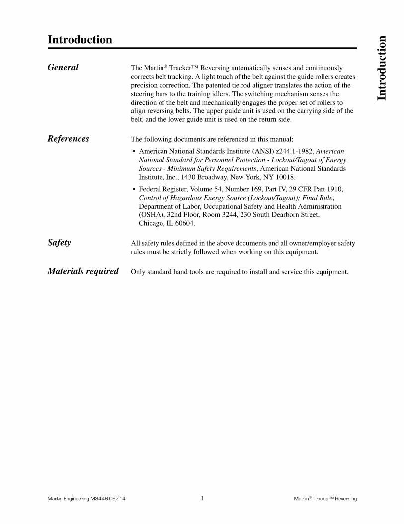
4.
CAUTION!
Failure to install bolts will causetorque arm assemblies to comeloose, causing damage tounit or conveyor belt.
Before installing bolts, applythread-sealing compound.
Inst
alla
tion

Martin Engineering M3446-06/14 7 Martin® Tracker™ Reversing
5.
CAUTION!
Failure to install bolts will causeupper guide roll assemblies tocome loose, causing damageto unit or conveyor belt.
Before installing bolts, applythread-sealing compound.
Inst
alla
tion

Martin Engineering M3446-06/14 8 Martin® Tracker™ Reversing
Z
CAUTION!
Make sure torque arm and cradleassemblies pivot freely. Do not tie offto restrict unit’s side-to-side movement.
6.
WARNING!
If installed overhead, secure unitto stringer with safety cables.
Z
Z
Inst
alla
tion
Z
Martin Engineering M3446-06/14 9 Martin® Tracker™ Reversing
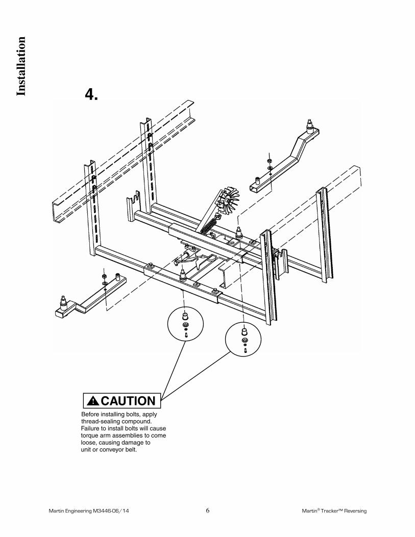
7.
1/4 in. (6 mm)
1/4 in. (6 mm)
Inst
alla
tion

Martin Engineering M3446-06/14 10 Martin® Tracker™ Reversing
Figure 8. Air Cylinder Controls
Installing air cylinder controls
WARNING!
All electrical work must be done to National Electrical Code (NEC) standards.
CAUTION!
Do not mount control solenoid in area subject to shock, vibration, temperatures exceeding 130°F (55°C), or explosion.
1. Determine location for control solenoid and mount onto wall with fasteners.
2. Using electrical connectors, route wires from solenoid valve to direction monitoring hardware.
3. Wire solenoid so circuit will close when conveyor changes direction.
IMPORTANTMartin Engineering recommends installing an air filter in the air supply line.
4. Install air supply line to control solenoid as shown in Figure 8.
5. Route two air lines from control solenoid to air cylinder.
6. Install elbows into ports on air cylinder.
7. Connect one air line to port A on solenoid valve and port A on air cylinder.
8. Connect other air line to port B on solenoid valve and port B on air cylinder.
Port A Port B
PRIMARYBELT DIRECTION
Port A Port B
Compressed Air Supply1/4-NPT 15 PSI minimum
(supplied by others)
Reversing Signal12VDC or 120VACClosed = Reversed
(supplied by others)
Port B is pressurized
when no signalis present.
CylinderHead
ControlSolenoid
Inst
alla
tion

Martin Engineering M3446-06/14 11 Martin® Tracker™ Reversing
9. Make sure air lines are not subject to wear or pinching. Anchor lines to prevent movement.
10. Apply air pressure to control solenoid.
Figure 9. Air Cylinder Switching Mechanism Orientation
11. Air cylinder switching mechanism should be installed so the cylinder is retracted and double v-latch near the cylinder cap end is engaged when the conveyor belt is rotating in its primary direction.
12. If double v-latch is not engaged on the correct side:
a. Switch air lines between ports A and B on cylinder.
13. If cylinder is extended when the belt is traveling in its primary direction:
a. Remove switching mechanism assembly.
b. Rotate mechanism 180 degrees.
c. Reinstall switching mechanism assembly.
PRIMARY
BELT D
IRECTIO
N
Inst
alla
tion

Martin Engineering M3446-06/14 12 Martin® Tracker™ Reversing
Installing upper guide unit
1. Locate upper guide unit beyond the loading point or three to four times the belt width before the point where belt needs adjustment. If installing multiple units, allow 70 to 150 ft. (21 to 50 m) between units depending on the severity of mistracking.
2. Remove existing troughing idler. Set aside for later use.
3. Install upper guide unit as shown in Figures 10 through 16.
10.
Inst
alla
tion

Martin Engineering M3446-06/14 13 Martin® Tracker™ Reversing
11.
CL
90°
90°
CL
CL
24.75(629)
IMPORTANT
X
X
Inst
alla
tion

Martin Engineering M3446-06/14 14 Martin® Tracker™ Reversing
CL
CL
12.
Weld pivot plateto troughing idler.
CAUTION!
Failure to install bolts will causetorque arm assemblies to comeloose, causing damage tounit or conveyor belt.
Before installing bolts, applythread-sealing compound.
CL
Inst
alla
tion
Martin Engineering M3446-06/14 15 Martin® Tracker™ Reversing
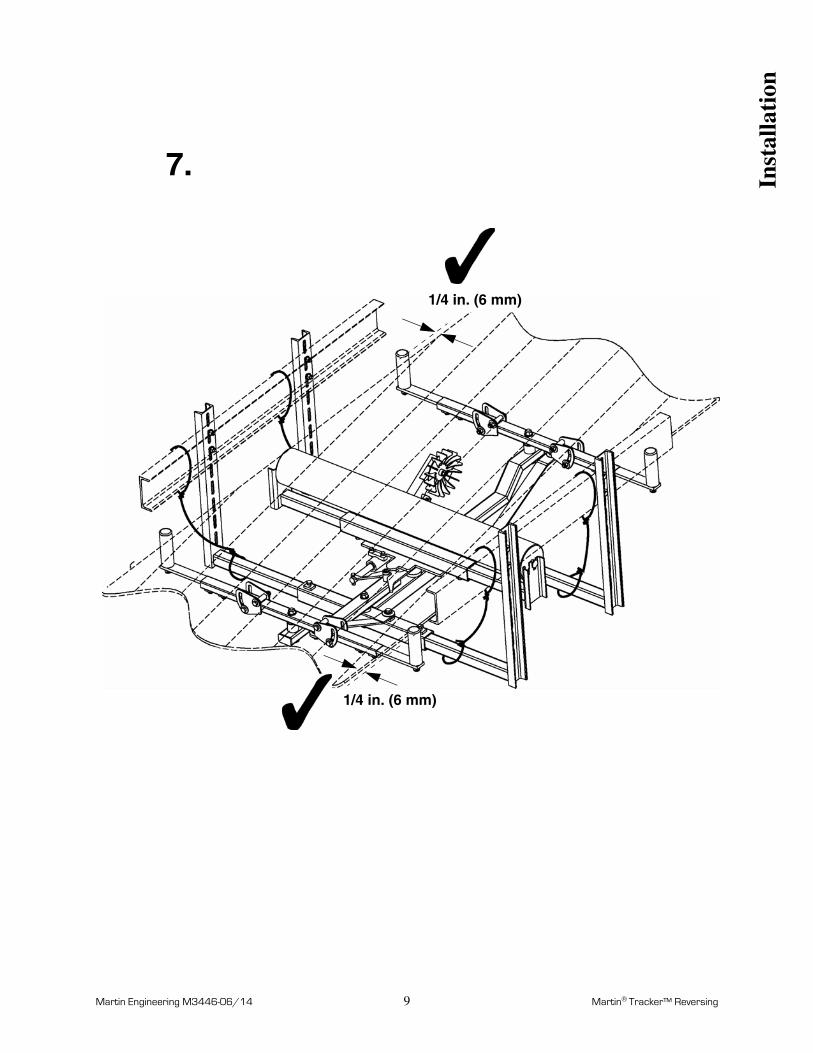
13.
CAUTION!
Failure to install bolts will causetorque arm assemblies to comeloose, causing damage tounit or conveyor belt.
Before installing bolts, applythread-sealing compound.
Inst
alla
tion

Martin Engineering M3446-06/14 16 Martin® Tracker™ Reversing
14.1/4 in. (6 mm)
Inst
alla
tion
Martin Engineering M3446-06/14 17 Martin® Tracker™ Reversing
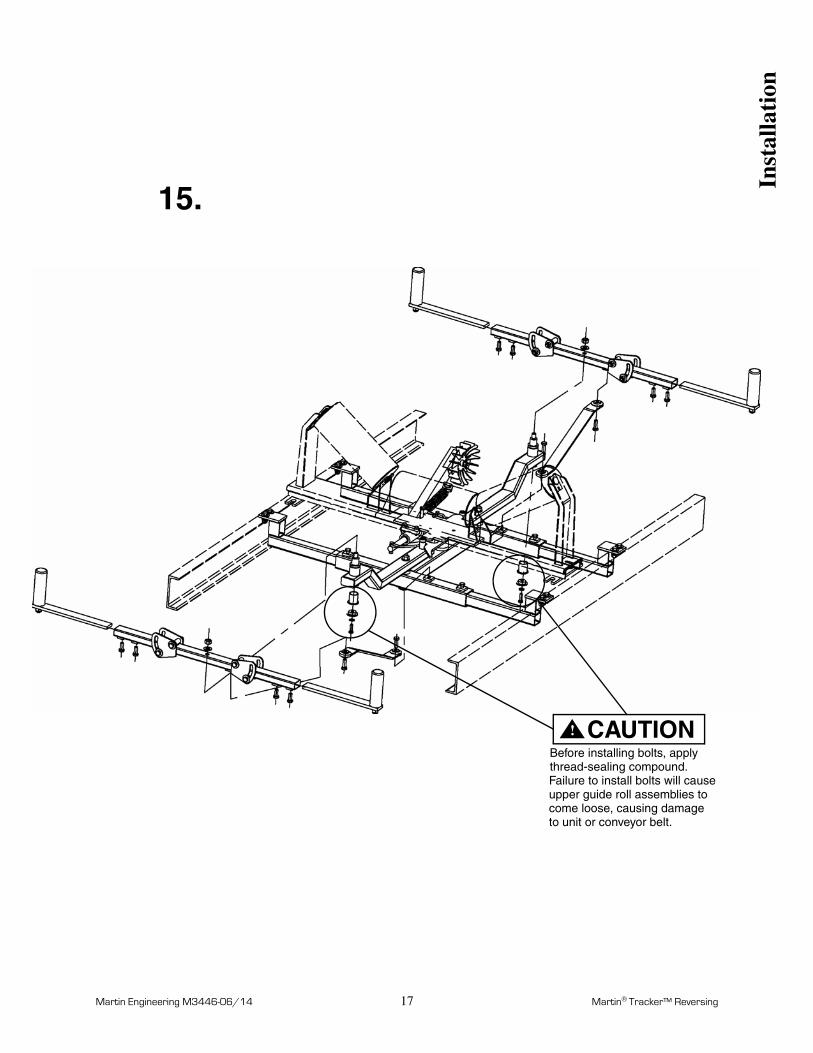
15.
CAUTION!
Failure to install bolts will causeupper guide roll assemblies tocome loose, causing damageto unit or conveyor belt.
Before installing bolts, applythread-sealing compound.
Inst
alla
tion

Martin Engineering M3446-06/14 18 Martin® Tracker™ Reversing
16.CAUTION!
Make sure torque arm and cradleassemblies pivot freely. Do not tie offto restrict unit’s side-to-side movement.
Y
Y
Y
Y
Y
Inst
alla
tion

Martin Engineering M3446-06/14 19 Martin® Tracker™ Reversing
After Installing Belt Tracking System
IMPORTANTRead entire section before beginning work.
CAUTION!
Martin Engineering recommends installing run-off sensors on conveyor. If switching mechanism fails, belt could be damaged.
1. Thoroughly wipe chute or stringers clean above Martin® Tracker™ Reversing on both sides of belt. Place Conveyor Products Warning Labels (P/N 23395) on chute or stringers visible to Martin® Tracker™ Reversing operator.
2. Make sure wheel on switching mechanism is not lifting conveyor belt off idler. If it is, adjust nut on eye bolt to lower wheel as follows:
a. See Figure 17. Loosen nut to lower wheel away from belt.
b. Tighten jam nut to set spring in place.
Figure 17. Adjusting Wheel on Switching Mechanism
WARNING!
Failure to remove tools from installation area and conveyor belt before turning on energy source can cause serious injury to personnel and damage to belt.
3. Remove all tools and fire retardant cover from installation area and conveyor belt.
Idler
Wheel
Eye bolt
Conveyor belt
Nut
Jam nut
Aft
er I
nsta
llati
on

Martin Engineering M3446-06/14 20 Martin® Tracker™ Reversing
DANGER!
Do not touch or go near conveyor belt or conveyor accessories when conveyor belt is running. Body or clothing can get caught and pull body into conveyor belt, causing severe injury or death.
WARNING!
Keep fingers away from spinning paddle wheel.
4. Turn on conveyor belt and observe belt tracking.
WARNING!
Before adjusting Martin® Tracker™ Reversing, turn off and lock out/tag out energy source to conveyor and conveyor accessories.
5. Allow belt to run through at least ten revolutions in one direction. Reverse direction of belt and run through at least ten revolutions in the opposite direction. Then turn off and lock out/tag out energy source according to ANSI standards (see “References”).
6. Make sure all fasteners are tight. Tighten if necessary.
7. See Figure 18. If necessary, adjust cross section (A) to fine tune belt tracking:
a. Loosen set screws (B) securing cross section on telescopic tubes (C).
b. Slide cross section on telescopic tubes in the direction belt needs to move as necessary for proper adjustment of cradle assembly (D) and idler (E). (Parallel stay (F) will move cradle assembly.)
Aft
er I
nsta
llati
on

Martin Engineering M3446-06/14 21 Martin® Tracker™ Reversing
Figure 18. Adjusting Martin® Tracker™ Reversing
A.
B.
C.
F.
Cross section
Set screw (2)
Telescopic tube (2)
Parallel stay
D.
E.
Cradle assembly
Idler (shown adjusted)
D
FA
BCEB
elt
Dir
ecti
on
Only one cross section and cradle assembly
IMPORTANT
will be affected by this adjustment. Toadjust opposite cross section and cradleassembly, switching mechanism (G) must beengaged for belt running in opposite direction.
G
G. Switching mechanism
Aft
er I
nsta
llati
on

Notes

Martin Engineering M3446-06/14 23 Martin® Tracker™ Reversing
Part Numbers
This section provides part numbers for the Martin® Tracker™ Reversing. Please reference part numbers when ordering parts.
Martin® Tracker™ Reversing Assemblies
Lower Unit Assemblies: See Figure 19.
24 to 36-in. (600 to 950-mm) belts: P/N 34694-L1R.
42 to 54-in. (1000 to 1400-mm) belts: P/N 34694-L2R.
60 to 72-in. (1400 to 1800-mm) belts: P/N 34694-L3R.
84-in. (1800 to 2200-mm) belts: P/N 34694-L4R.
Lower Unit Assemblies with Air Cylinder: See Figure 20.
24 to 36-in. (600 to 950-mm) belts: P/N 34694-L1RA.
42 to 54-in. (1000 to 1400-mm) belts: P/N 34694-L2RA.
60 to 72-in. (1400 to 1800-mm) belts: P/N 34694-L3RA.
84-in. (1800 to 2200-mm) belts: P/N 34694-L4RA.
Upper Unit Assemblies: See Figure 21.
24 to 36-in. (600 to 950-mm) belts: P/N 34695-U1R.
42 to 54-in. (1000 to 1400-mm) belts: P/N 34695-U2R.
60 to 72-in. (1400 to 1800-mm) belts: P/N 34695-U3R.
84-in. (1800 to 2200-mm) belts: P/N 34695-U4R.
Air Cylinder Control Assembly: P/N 39292-XXX. See Figure 22.
Par
t N
umbe
rs

Martin Engineering M3446-06/14 24 Martin® Tracker™ Reversing
Figure 19. Martin® Tracker™ Reversing (Lower Unit), P/N 34694-LXR* (Sheet 1 of 2)
Arm Weldment for 34694-L3R and 34694-L4R
14
12
2426,27,28
11
9
8
17
5
15
16
4
25
22
1
20,3530
13
Mounting
23
3
2
10
7
20
21
6
19
18
29
31,32,33,3421
HardwareP/N 34760-R
Par
t N
umbe
rs

Martin Engineering M3446-06/14 25 Martin® Tracker™ Reversing
Figure 19. Martin® Tracker™ Reversing (Lower Unit), P/N 34694-LXR* (Sheet 2 of 2)* If ordering item 5, purchase 22 also.Not Shown: Operators Manual (P/N M3446); Label Kit (P/N 34772-R); LOCTITE® Capsule (P/N 35433).
Part Number 34694- L1R / L2R L3R / L4R
Item Description Part No. Qty Part No. Qty
1 H-Frame Weldment 38075-00 1 38075-01 1
2 Bearing Flanged 37467 9 37467 8
3 Bearing Straight 38080 1 35869 1
4 Telescoping Tube Weldment 34743-01 / 34743-02 4 34743-04 / 34743-05 4
*5 Switching Mechanism Assembly 35661-00 1 35661-01 1
6 Swing Torque Shaft 37414-05 2 37414-03 4
7 Bearing Holder Cap 36939 4 36939 4
8 Arm Torque Weldment 34733-00UR 2 34733-01UR 2
9 Screw Shoulder 3/4 x 2-3/4 37267 2 37267 2
10 Torque Arm Bushing 37268 2 37268 2
11 Swing Torque Shaft 37414-02 2 37414-03 4
12 Cradle Weldment 38081-00 2 38081-01 2
13 Cradle Wing Tube Weldment 37458-02 / 37466 4 37283-01 4
14 Arm Guide Roll Assembly 35205-06 / 35205-02 4 35205-03 / 35205-04 4
15 Telescoping Idler Tube Weldment (Right) 34745-01R / 34745-02R 1
16 Telescoping Idler Tube Weldment (Left) 34745-01L / 34745-02L 1
17 Stay Parallel Weldment 35207-UR 2 35207-01UR 2
18 Washer Compression 5/8 11752 6 11752 6
19 Hex Nut 5/8-11NC ZP 11772 6 11772 6
20 Washer Compression 3/8 11747 4 11747 12
21 Screw HHC 3/8-16NC x 1-1/4 ZP 12215 4 12215 12
*22 Screw HHC 3/8-16NC 38088 1 16098 1
23Screw HHC 1/2-13NC x 1-1/2 ZP 11763 4
Screw HHC 3/4-10NC x 1-1/2 ZP 26262 4
24 Screw HHC 1/2-13NC x 1-1/4 ZP 13835 2/4 13835 8
25 Screw HHC 1/2-13NC X 1 ZP 13842 6 13842 12
26 Flat Washer 1/2 wide ZP 17328 16 17328 16
27 Screw HHC 1/2-13NC x 3-1/2 ZP M921 8 M921 8
28 Hex Nut Elastic Lock 1/2-13NC ZP 18577 8 18577 8
29 Plug for Tube 34714 4 35322 4
30 Telescoping Idler Tube Weldment 38031-H2 / 38031-H3 2
31 Telescoping Idler Tube Upright 38029-01RP 1
32 Telescoping Idler Tube Upright 38029-01LP 1
33 Telescoping Idler Tube Upright 38029-00RP 1
34 Telescoping Idler Tube Upright 38029-00LP 1
35 Hex Nut Elastic Lock 3/8-16NC ZP 14201 8
36 Bearing Flanged 35870 1
Par
t N
umbe
rs
Martin Engineering M3446-06/14 26 Martin® Tracker™ Reversing
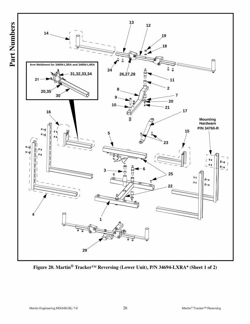
Figure 20. Martin® Tracker™ Reversing (Lower Unit), P/N 34694-LXRA* (Sheet 1 of 2)
Arm Weldment for 34694-L3RA and 34694-L4RA
14
12
2426,27,28
11
9
8
17
5 15
16
4
25
22
1
20,3530
13
Mounting
23
3
2
10
7
20
21
6
19
18
29
31,32,33,3421
HardwareP/N 34760-R
Par
t N
umbe
rs

Martin Engineering M3446-06/14 27 Martin® Tracker™ Reversing
Figure 20. Martin® Tracker™ Reversing (Lower Unit), P/N 34694-LXRA* (Sheet 2 of 2)* If ordering item 5, purchase 22 also.Not Shown: Operators Manual (P/N M3446); Label Kit (P/N 34772-R); LOCTITE® Capsule (P/N 35433); Cylinder Control Assembly (P/N 39292-120 or 39292-24)
Part Number 34694- L1RA / L2RA L3RA / L4RA
Item Description Part No. Qty Part No. Qty
1 H-Frame Weldment 38075-00 1 38075-01 1
2 Bearing Flanged 37467 9 37467 8
3 Bearing Straight 38080 1 35869 1
4 Telescoping Tube Weldment 34743-01 / 34743-02 4 34743-04 / 34743-05 4
*5 Switching Mechanism Assembly 35661-00A 1 35661-01A 1
6 Swing Torque Shaft 37414-05 2 37414-03 4
7 Bearing Holder Cap 36939 4 36939 4
8 Arm Torque Weldment 34733-00UR 2 34733-01UR 2
9 Screw Shoulder 3/4 x 2-3/4 37267 2 37267 2
10 Torque Arm Bushing 37268 2 37268 2
11 Swing Torque Shaft 37414-02 2 37414-03 4
12 Cradle Weldment 38081-00 2 38081-01 2
13 Cradle Wing Tube Weldment 37458-02 / 37466 4 37283-01 4
14 Arm Guide Roll Assembly 35205-06 / 35205-02 4 35205-03 / 35205-04 4
15 Telescoping Idler Tube Weldment (Right) 34745-01R / 34745-02R 1
16 Telescoping Idler Tube Weldment (Left) 34745-01L / 34745-02L 1
17 Stay Parallel Weldment 35207-UR 2 35207-01UR 2
18 Washer Compression 5/8 11752 6 11752 6
19 Hex Nut 5/8-11NC ZP 11772 6 11772 6
20 Washer Compression 3/8 11747 4 11747 12
21 Screw HHC 3/8-16NC x 1-1/4 ZP 12215 4 12215 12
*22 Screw HHC 3/8-16NC 38088 1 16098 1
23Screw HHC 1/2-13NC x 1-1/2 ZP 11763 4
Screw HHC 3/4-10NC x 1-1/2 ZP 26262 4
24 Screw HHC 1/2-13NC x 1-1/4 ZP 13835 2/4 13835 8
25 Screw HHC 1/2-13NC X 1 ZP 13842 6 13842 12
26 Flat Washer 1/2 wide ZP 17328 16 17328 16
27 Screw HHC 1/2-13NC x 3-1/2 ZP M921 8 M921 8
28 Hex Nut Elastic Lock 1/2-13NC ZP 18577 8 18577 8
29 Plug for Tube 34714 4 35322 4
30 Telescoping Idler Tube Weldment 38031-H2 / 38031-H3 2
31 Telescoping Idler Tube Upright 38029-01RP 1
32 Telescoping Idler Tube Upright 38029-01LP 1
33 Telescoping Idler Tube Upright 38029-00RP 1
34 Telescoping Idler Tube Upright 38029-00LP 1
35 Hex Nut Elastic Lock 3/8-16NC ZP 14201 8
36 Bearing Flanged 35870 1
Par
t N
umbe
rs

Martin Engineering M3446-06/14 28 Martin® Tracker™ Reversing
Figure 21. Martin® Tracker™ Reversing (Upper Unit), P/N 34695-UXR* (Sheet 1 of 2)
14 1224,25,26
13
22
11
8
15
21
5
20
1
423
1716
2
7
18
19
27
9
10
3
6
7
18
19
MountingHardware
P/N 34760-R
Par
t N
umbe
rs

Martin Engineering M3446-06/14 29 Martin® Tracker™ Reversing
Figure 21. Martin® Tracker™ Reversing (Upper Unit), P/N 34695-UXR* (Sheet 2 of 2)
* If ordering item 5, purchase 20 also.Not Shown: Operators Manual (P/N M3446); Label Kit (P/N 34772-R); LOCTITE® Capsule (P/N 35433).
Part Number 34695- U1R / U2R U3R / U4R
Item Description Part No. Qty Part No. Qty
1 H-Frame Weldment 308075-00 1 308075-01 1
2 Bearing Flanged 37467 9 37467 8
3 Bearing Straight 38080 1 35869 1
4 Telescoping Tube Weldment 34742-01R / 34742-02R 4 34742-03R / 34742-04R 4
*5 Switching Mechanism Assembly 35662-00 1 35662-01 1
6 Swing Torque Shaft 37414-05 2 37414-03 4
7 Bearing Holder Cap 36939 4 36939 4
8 Arm Torque Weldment 34733-00UR 2 34733-01UR 2
9 Screw Shoulder 3/4 x 2-3/4 37267 2 37267 2
10 Torque Arm Bushing 37268 2 37268 2
11 Swing Torque Shaft 37414-02 2 37414-03 2
12 Cradle Weldment 38081-00 2 38081-01 2
13 Cradle Wing Tube Weldment 37458-02 / 37466 4 37283-01 4
14 Arm Guide Roll Assembly 35205-06 / 35205-02 4 35205-03 / 35205-04 4
15 Stay Parallel Weldment 35207-UR 2 35207-01UR 2
16 Washer Compression 5/8 11752 6 11752 6
17 Hex Nut 5/8-11NC ZP 11772 6 11772 6
18 Washer Compression 3/8 11747 4 11747 4
19 Screw HHC 3/8-16NC x 1-1/4 ZP 12215 4 12215 4
*20 Screw HHC 3/8-16NC 38088 1 16098 1
21Screw HHC1/2-13NC x 1-1/2 ZP 11763 4
Screw HHC 3/4-10NC x 1-1/2 ZP 26262 4
22 Screw HHC 1/2-13NC x 1-1/4 ZP 13835 4/8 13835 8
23 Screw HHC 1/2-13NC X 1 ZP 13842 4 13842 8
24 Flat Washer 1/2 wide ZP 17328 16 17328 16
25 Screw HHC 1/2-13NC x 3-1/2 ZP M921 8 M921 8
26 Hex Nut Elastic Lock 1/2-13NC ZP 18577 8 18577 8
27 Plug for Tube 34714 4 35322 4
28 Bearing Flanged 35870 1P
art
Num
bers

Martin Engineering M3446-06/14 30 Martin® Tracker™ Reversing
Figure 22. Martin® Tracker™ Reversing Cylinder Control Assembly, P/N 39292-XXX(Sheet 1 of 2)
89
710
6
14
15
16
17,18,19
3
20,21,22 2
1
12,13
5
4
11
Par
t N
umbe
rs

Martin Engineering M3446-06/14 31 Martin® Tracker™ Reversing
Figure 22. Martin® Tracker™ Reversing Cylinder Control Assembly, P/N 39292-XXX(Sheet 2 of 2)
Item Description Part No. Qty
1 Base Weldment 39290-W 1
2 Cover 39290-C 1
3 Spring Loaded Slide Latch 39290-L 1
4 Screw HHC 1/4-20NC x 2-1/2 ZP 33668 2
5 Solenoid Stand-Off 39293-S 2
6 Valve 4-way 1/439293-120 (120VAC)
139293-24 (24VDC)
7 Nipple 1/4 NPT x 1-1/2 34812 1
8 Regulator 1/4 NPT 60 PSI 14728 1
9 Gauge Liquid Filled 1/8 NPT 30437 1
10 Muffler Air 1/4 NPT 31623 2
11 Elbow Street 3/8 NPT Brass 37191 1
12 Washer Lock Helical Spring 1/4 ZP 11894 2
13 Nut Hex 1/4-20NC ZP 11769 2
14 Hose Barb 1/4 NPT to 1/4 Hose 17224 2
15 Hose Barb 3/8 NPT to 1/4 Hose 39306 2
16 Elbow Street 3/8 NPT Brass 34269 2
17 Pin Clevis 1/4 x 1/2 ZP 39307 2
18 Washer Flat 1/4 Narrow ZP 39308 4
19 Pin Cotter 1/16 x 1/2 ZP 39309 2
20 Screw RHMS #8-32NC x 3/8 20158 2
21 Washer Lock Helical Spring #8 ZP 28675 2
22 Nut Hex #8-32NC ZP 27017 2
23 (NS) Label Martin Product 38048 2
24 (NS) Screw HHC 5/16-18NC x 1.25 ZP 39142 4
25 (NS) Washer Compression 5/16 17083 4
26 (NS) Nut Hex 5/16-18NC ZP 11963 4
27 (NS) Hose Push-Lok 1/4 21241 30’
28 (NS) Manual Operator’s M3446 1
Par
t N
umbe
rs

Martin Engineering M3446-06/14 32 Martin® Tracker™ Reversing
Figure 23. Conveyor Products Warning Label, P/N 23395
Figure 24. Pinch Point Warning Label, P/N 30528
Lock out and/or tag out all energy sources to
Cierre y/o rotule todas las fuentes de energía al
conveyor system and loading system before performing any work on conveyor or conveyoraccessories. Failure to do so could result insevere injury or death.
sistema transportador y al sistema de carga antesde realizar cualquier trabajo sobre el transportadoro sobre los accesorios del transportador. Si nose procede asi, puede resultar en heridas seriaso muerte.
Lock out and/or tag out all energy sources to
Cierre y/o rotule todas las fuentes de energía al
Label P/N 23395
conveyor system and loading system before performing any work on conveyor or conveyoraccessories. Failure to do so could result insevere injury or death.
sistema transportador y al sistema de carga antesde realizar cualquier trabajo en el transportadoro sus accesorios. El no hacerlo puede resultaren heridas serias o muerte.
ADVERTENCIAWARNING!
!
Pinch point!
Label P/N 30528
!WARNING!
ADVERTENCIA!
¡Usted se puedepellizcar!
Par
t N
umbe
rs

Martin Engineering M3446-06/14 A-1 Martin® Tracker™ Reversing
AppendixMartin® Tracker™ Reversing Dimensions
App
endi
x

Martin Engineering M3446-06/14 A-2 Martin® Tracker™ Reversing
GF
E
C
A
B
D
H
Martin® Tracker™ Reversing Lower Unit Dimensions
App
endi
x
Assembly P/NBelt Widthin. (mm)
Dimensions—in. (mm)
A (Max.) B C D E F G H
34694-L1R &34694-L1RA
24-36 (600-950)52
(1321)25.60(650)
24.75(629)
30.29(769)
4.75(120)
6.30(160)
65.05(1652)
3.00(76)
34694-L2R &34694-L2RA
42-54 (1000-1400)66
(1676)25.60(650)
24.75(629)
30.29(769)
4.75(120)
6.30(160)
65.05(1652)
3.00(76)
34694-L3R &34694-L3RA
60-72 (1400-1800)84
(2134)47.25(1200)
24.75(629)
34.29(871)
9.84(250)
9.00(229)
64.26(1632)
4.00(102)
34694-L4R &34694-L4RA
84 (1800-2200)96
(2438)47.25(1200)
24.75(629)
34.29(871)
9.84(250)
9.00(229)
64.26(1632)
4.00(102)
Martin Engineering M3446-06/14 A-3 Martin® Tracker™ Reversing
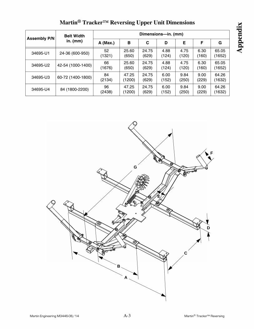
Martin® Tracker™ Reversing Upper Unit Dimensions
App
endi
x
Assembly P/NBelt Widthin. (mm)
Dimensions—in. (mm)
A (Max.) B C D E F G
34695-U1 24-36 (600-950)52
(1321)25.60(650)
24.75(629)
4.88(124)
4.75(120)
6.30(160)
65.05(1652)
34695-U2 42-54 (1000-1400)66
(1676)25.60(650)
24.75(629)
4.88(124)
4.75(120)
6.30(160)
65.05(1652)
34695-U3 60-72 (1400-1800)84
(2134)47.25(1200)
24.75(629)
6.00(152)
9.84(250)
9.00(229)
64.26(1632)
34695-U4 84 (1800-2200)96
(2438)47.25(1200)
24.75(629)
6.00(152)
9.84(250)
9.00(229)
64.26(1632)
D
A
B
C
E
F
G

Notes

Any product, process, or technology described here may be the subject of intellectual property rights reserved by Martin Engineering Company. Trademarks or service marks designated with the ® symbol are registered with the U.S. Patent and Trademark Office and may be proprietary in one or more countries or regions. Other trademarks and service marks belonging to Martin Engineering Company in the United States and/or other countries or regions may be designated with the “TM” and “SM” symbols. Brands, trademarks, and names of other parties, who may or may not be affiliated with, connected to, or endorsed by Martin Engineering Company, are identified wherever possible. Additional information regarding Martin Engineering Company’s intellectual property can be obtained at www.martin-eng.com/trademarks.

Martin Engineering USAOne Martin PlaceNeponset, IL 61345-9766 USA800 544 2947 or 309 852 2384Fax 800 814 1553www.martin-eng.com
Form No. M3446-06/14 © Martin Engineering Company 1999, 2014


![Reversing and Malware Analysis Training Articles [2012] . cracking/Reversing... · Reversing and Malware Analysis Training Articles ... Step 1: Start with what you ... Reversing and](https://static.fdocuments.us/doc/165x107/5ab905fd7f8b9ac10d8db0ab/reversing-and-malware-analysis-training-articles-2012-crackingreversingreversing.jpg)