Martin Benson - Efficient Conveyor Design - The application of an efficient conveyor design service
80
-
Upload
informa-australia -
Category
Business
-
view
178 -
download
0
Transcript of Martin Benson - Efficient Conveyor Design - The application of an efficient conveyor design service

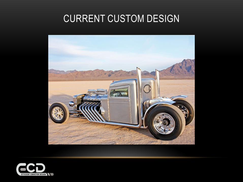
CURRENT CUSTOM DESIGN

BASE DESIGN:
2 WHEEL DRIVE

BASE DESIGN PLUS:
4 WHEEL DRIVE
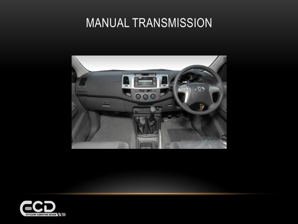
MANUAL TRANSMISSION
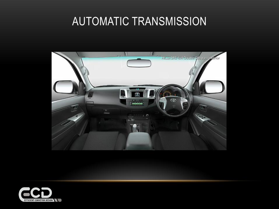
AUTOMATIC TRANSMISSION

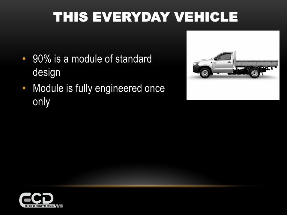
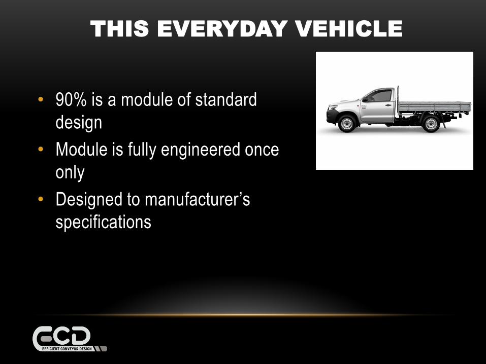
THIS EVERYDAY VEHICLE
• 90% is a module of standard
design
THIS EVERYDAY VEHICLE
• 90% is a module of standard
design
• Module is fully engineered once
only
THIS EVERYDAY VEHICLE
• 90% is a module of standard
design
• Module is fully engineered once
only
• Designed to manufacturer’s
specifications
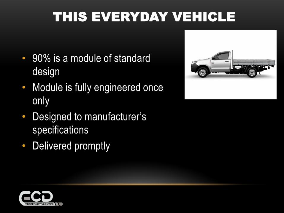
THIS EVERYDAY VEHICLE
• 90% is a module of standard
design
• Module is fully engineered once
only
• Designed to manufacturer’s
specifications
• Delivered promptly
ECD DESIGN PHILOSOPHY
• Standard base design
• Standard options
• Designed to ECD specifications
RESULT
• Faster design process
• More efficient design process
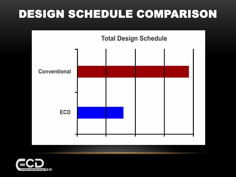
DESIGN SCHEDULE COMPARISON


BENEFIT TO CLIENT
BENEFIT TO CLIENT
• REDUCE PROJECT COST
BENEFIT TO CLIENT
• REDUCE PROJECT COST
• HAND OVER EARLIER
BENEFIT TO CLIENT
• REDUCE PROJECT COST
• HAND OVER EARLIER
• PRODUCE SOONER
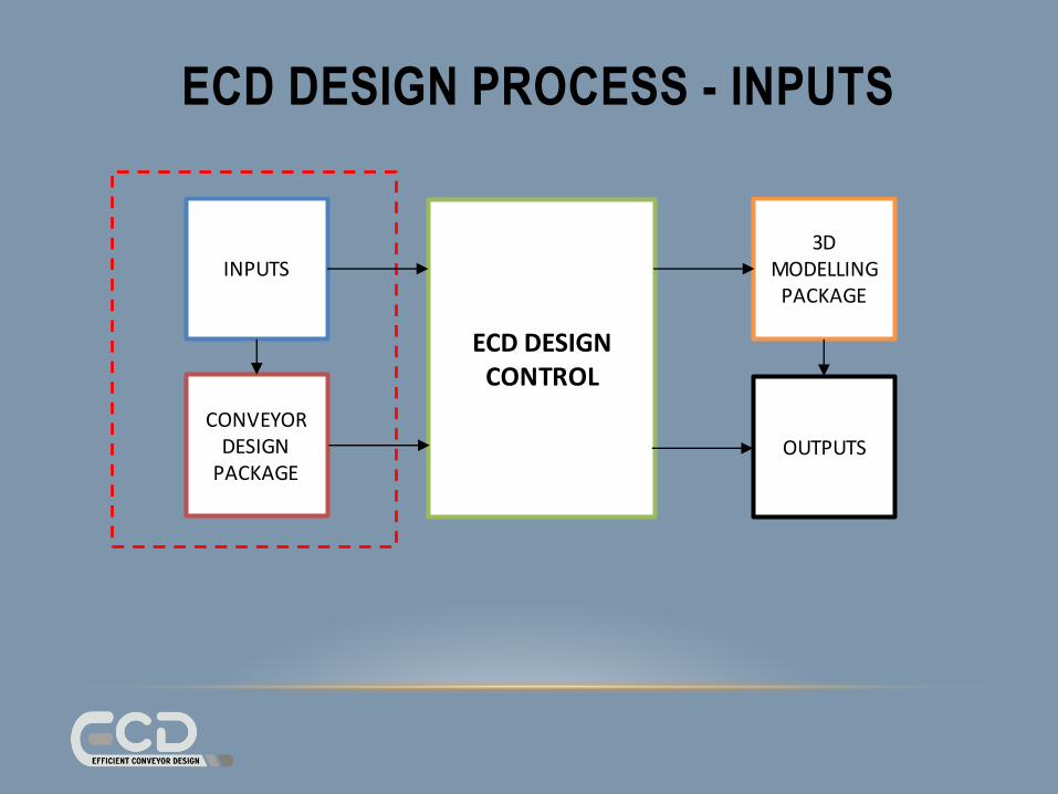
ECD DESIGN PROCESS
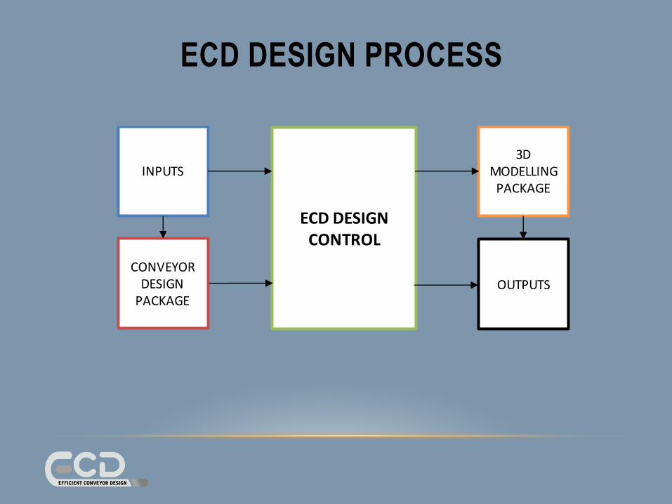
ECD DESIGN PROCESS
INPUTS
CONVEYORDESIGN
PACKAGE
ECD DESIGNCONTROL
3D MODELLING
PACKAGE
OUTPUTS

ECD DESIGN PROCESS
INPUTS
CONVEYORDESIGN
PACKAGE
ECD DESIGNCONTROL
3D MODELLING
PACKAGE
OUTPUTS
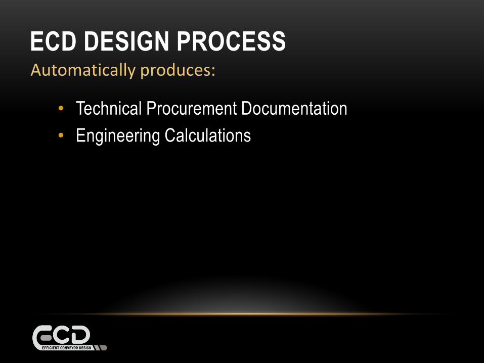
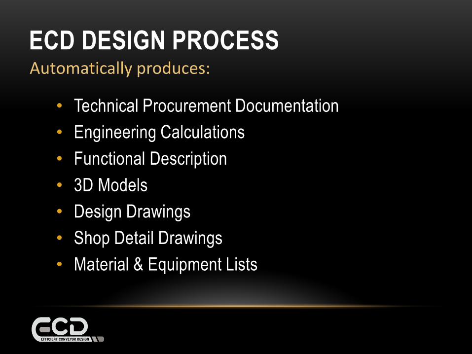
Automatically produces:
ECD DESIGN PROCESS
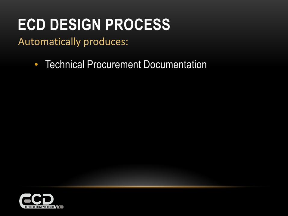
• Technical Procurement Documentation
Automatically produces:
ECD DESIGN PROCESS
• Technical Procurement Documentation
• Engineering Calculations
Automatically produces:
ECD DESIGN PROCESS
• Technical Procurement Documentation
• Engineering Calculations
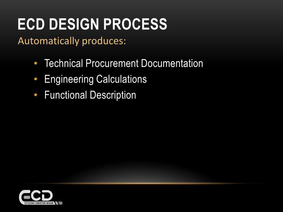
• Functional Description
Automatically produces:
ECD DESIGN PROCESS

• Technical Procurement Documentation
• Engineering Calculations
• Functional Description
• 3D Models
Automatically produces:
ECD DESIGN PROCESS
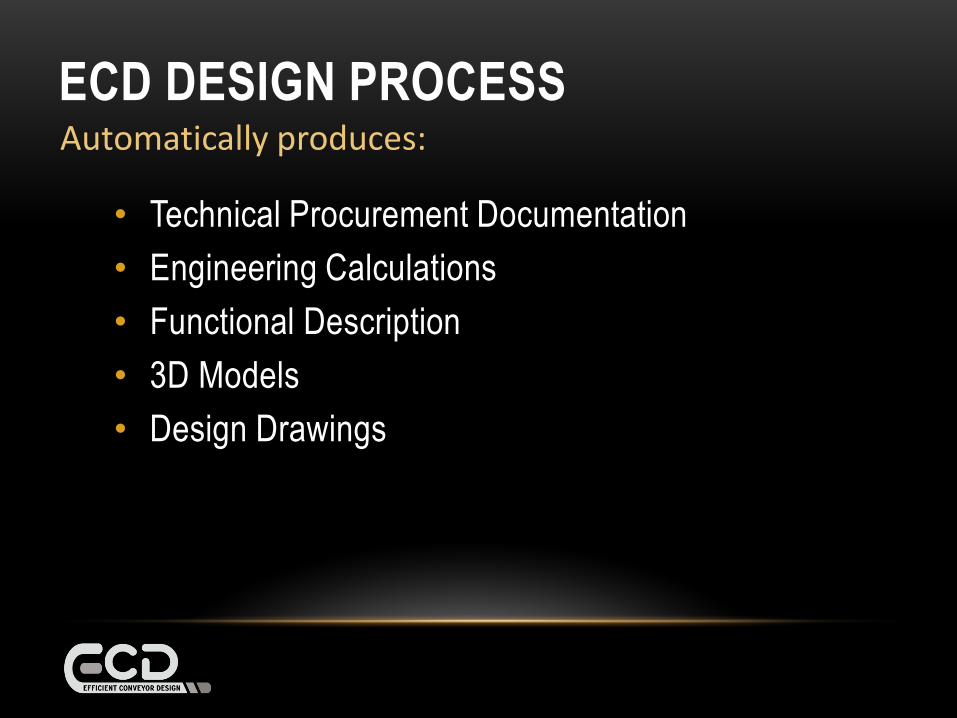
• Technical Procurement Documentation
• Engineering Calculations
• Functional Description
• 3D Models
• Design Drawings
Automatically produces:
ECD DESIGN PROCESS
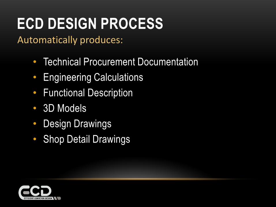
• Technical Procurement Documentation
• Engineering Calculations
• Functional Description
• 3D Models
• Design Drawings
• Shop Detail Drawings
Automatically produces:
ECD DESIGN PROCESS
• Technical Procurement Documentation
• Engineering Calculations
• Functional Description
• 3D Models
• Design Drawings
• Shop Detail Drawings
• Material & Equipment Lists
Automatically produces:
ECD DESIGN PROCESS
ECD DESIGN PROCESS - INPUTS
INPUTS
CONVEYORDESIGN
PACKAGE
ECD DESIGNCONTROL
3D MODELLING
PACKAGE
OUTPUTS
• Key design inputs
ECD DESIGN PROCESS
INPUTS:
• Key design inputs
• Client input on standard form
ECD DESIGN PROCESS
INPUTS:
• Key design inputs
• Client input on standard form
• Process up to 5 conveyors simultaneously
ECD DESIGN PROCESS
INPUTS:
• Key design inputs
• Client input on standard form
• Process up to 5 conveyors simultaneously
• Facility for direct Input of known vendor data
ECD DESIGN PROCESS
INPUTS:

ECD DESIGN PROCESS – DESIGN CONTROL
INPUTS
CONVEYORDESIGN
PACKAGE
ECD DESIGNCONTROL
3D MODELLING
PACKAGE
OUTPUTS
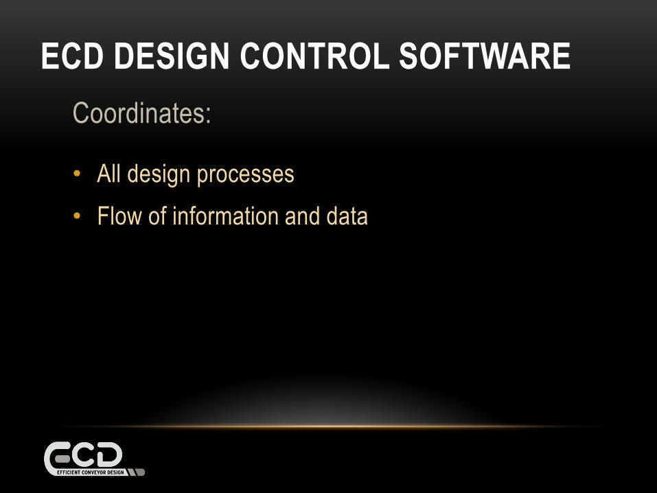
ECD DESIGN CONTROL SOFTWARE
Coordinates:
ECD DESIGN CONTROL SOFTWARE
Coordinates:
• All design processes
ECD DESIGN CONTROL SOFTWARE
Coordinates:
• All design processes
• Flow of information and data

ECD DESIGN CONTROL SOFTWARE
Coordinates:
• All design processes
• Flow of information and data
• Provides version control
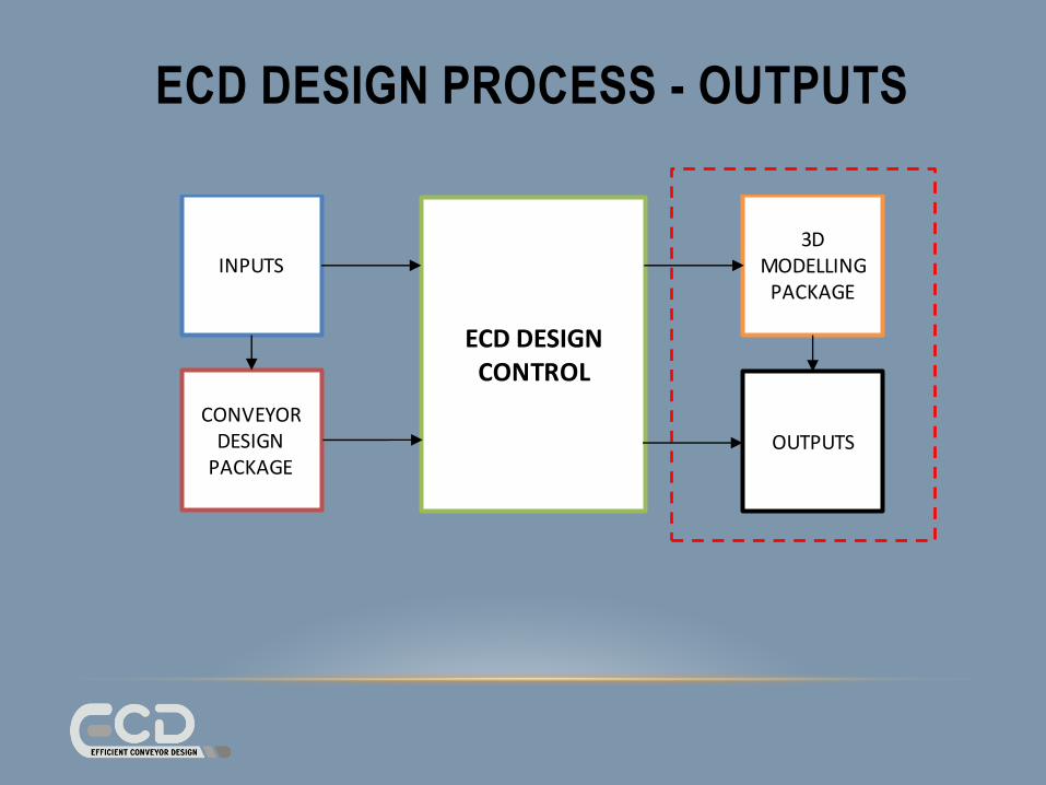
ECD DESIGN PROCESS - OUTPUTS
INPUTS
CONVEYORDESIGN
PACKAGE
ECD DESIGNCONTROL
3D MODELLING
PACKAGE
OUTPUTS
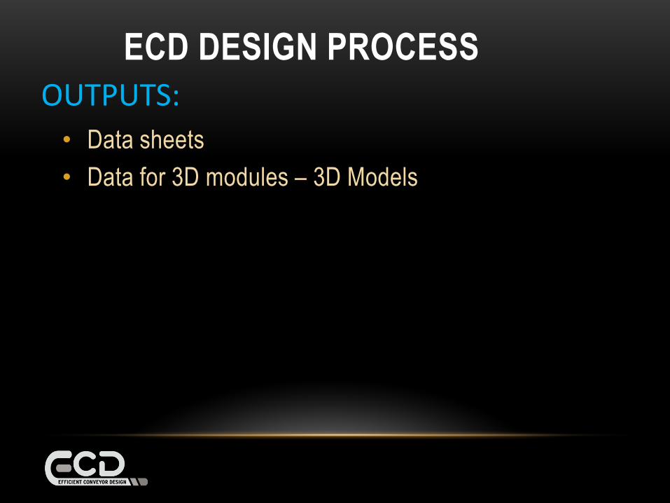
• Data sheets
OUTPUTS:
ECD DESIGN PROCESS
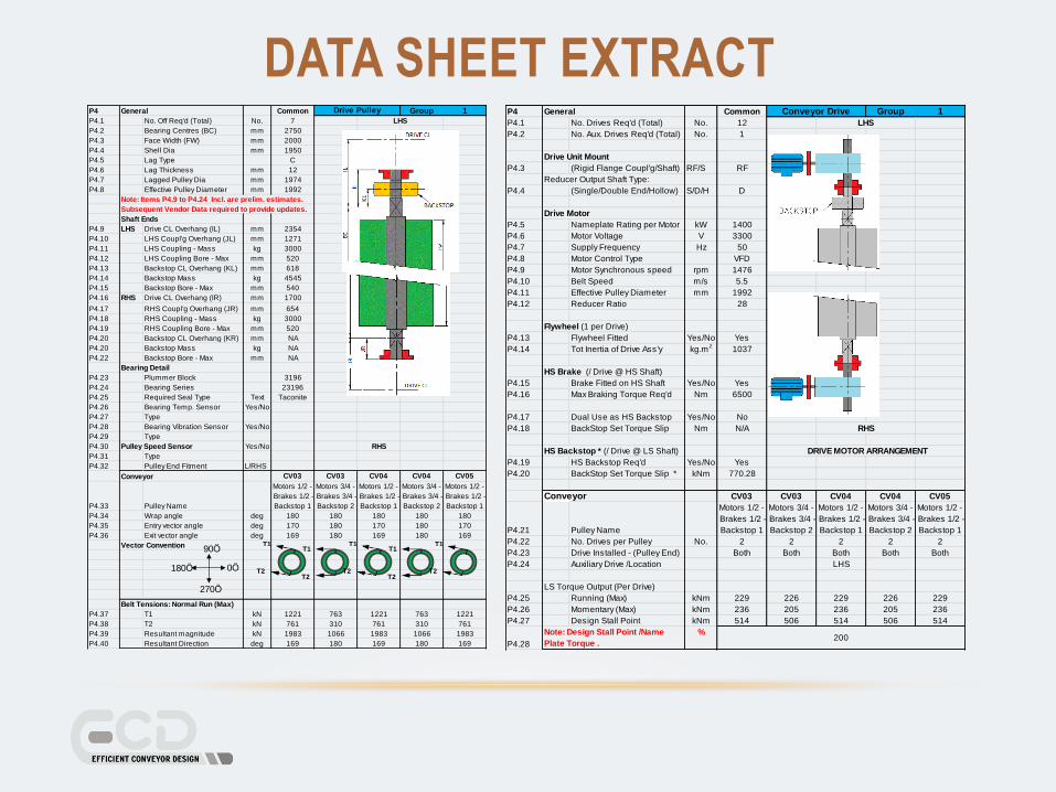
DATA SHEET EXTRACTP4 General Common Group 1
P4.1 No. Off Req'd (Total) No. 7
P4.2 Bearing Centres (BC) mm 2750
P4.3 Face Width (FW) mm 2000
P4.4 Shell Dia mm 1950
P4.5 Lag Type C
P4.6 Lag Thickness mm 12
P4.7 Lagged Pulley Dia mm 1974
P4.8 Effective Pulley Diameter mm 1992
Shaft Ends
P4.9 LHS Drive CL Overhang (IL) mm 2354
P4.10 LHS Coupl'g Overhang (JL) mm 1271
P4.11 LHS Coupling - Mass kg 3000
P4.12 LHS Coupling Bore - Max mm 520
P4.13 Backstop CL Overhang (KL) mm 618
P4.14 Backstop Mass kg 4545
P4.15 Backstop Bore - Max mm 540
P4.16 RHS Drive CL Overhang (IR) mm 1700
P4.17 RHS Coupl'g Overhang (JR) mm 654
P4.18 RHS Coupling - Mass kg 3000
P4.19 RHS Coupling Bore - Max mm 520
P4.20 Backstop CL Overhang (KR) mm NA
P4.20 Backstop Mass kg NA
P4.22 Backstop Bore - Max mm NA
Bearing Detail
P4.23 Plummer Block 3196
P4.24 Bearing Series 23196
P4.25 Required Seal Type Text Taconite
P4.26 Bearing Temp. Sensor Yes/No
P4.27 Type
P4.28 Bearing Vibration Sensor Yes/No
P4.29 Type
P4.30 Pulley Speed Sensor Yes/No RHS
P4.31 Type
P4.32 Pulley End Fitment L/RHS
Conveyor CV03 CV03 CV04 CV04 CV05
P4.33 Pulley Name
Motors 1/2 -
Brakes 1/2 -
Backstop 1
Motors 3/4 -
Brakes 3/4 -
Backstop 2
Motors 1/2 -
Brakes 1/2 -
Backstop 1
Motors 3/4 -
Brakes 3/4 -
Backstop 2
Motors 1/2 -
Brakes 1/2 -
Backstop 1
P4.34 Wrap angle deg 180 180 180 180 180
P4.35 Entry vector angle deg 170 180 170 180 170
P4.36 Exit vector angle deg 169 180 169 180 169
Vector Convention
Belt Tensions: Normal Run (Max)
P4.37 T1 kN 1221 763 1221 763 1221
P4.38 T2 kN 761 310 761 310 761
P4.39 Resultant magnitude kN 1983 1066 1983 1066 1983
P4.40 Resultant Direction deg 169 180 169 180 169
Drive Pulley
LHS
Note: Items P4.9 to P4.24 Incl. are prelim. estimates.
Subsequent Vendor Data required to provide updates.
90
0
270
180
T1
T2
T1
T2
T1
T2
T1
T2
T1
T2
P4 General Common Group 1
P4.1 No. Drives Req'd (Total) No. 12
P4.2 No. Aux. Drives Req'd (Total) No. 1
P4.3 (Rigid Flange Coupl'g/Shaft) RF/S RF
Reducer Output Shaft Type:
P4.4 (Single/Double End/Hollow) S/D/H D
P4.5 Nameplate Rating per Motor kW 1400
P4.6 Motor Voltage V 3300
P4.7 Supply Frequency Hz 50
P4.8 Motor Control Type VFD
P4.9 Motor Synchronous speed rpm 1476
P4.10 Belt Speed m/s 5.5
P4.11 Effective Pulley Diameter mm 1992
P4.12 Reducer Ratio 28
P4.13 Flywheel Fitted Yes/No Yes
P4.14 Tot Inertia of Drive Ass'y kg.m2
1037
P4.15 Brake Fitted on HS Shaft Yes/No Yes
P4.16 Max Braking Torque Req'd Nm 6500
P4.17 Dual Use as HS Backstop Yes/No No
P4.18 BackStop Set Torque Slip Nm N/A
P4.19 HS Backstop Req'd Yes/No Yes
P4.20 BackStop Set Torque Slip * kNm 770.28
Conveyor CV03 CV03 CV04 CV04 CV05
P4.21 Pulley Name
Motors 1/2 -
Brakes 1/2 -
Backstop 1
Motors 3/4 -
Brakes 3/4 -
Backstop 2
Motors 1/2 -
Brakes 1/2 -
Backstop 1
Motors 3/4 -
Brakes 3/4 -
Backstop 2
Motors 1/2 -
Brakes 1/2 -
Backstop 1
P4.22 No. Drives per Pulley No. 2 2 2 2 2
P4.23 Drive Installed - (Pulley End) Both Both Both Both Both
P4.24 Auxiliary Drive /Location LHS
LS Torque Output (Per Drive)
P4.25 Running (Max) kNm 229 226 229 226 229
P4.26 Momentary (Max) kNm 236 205 236 205 236
P4.27 Design Stall Point kNm 514 506 514 506 514
P4.28
%
Conveyor Drive
LHS
Drive Unit Mount
Drive Motor
Flywheel (1 per Drive)
HS Brake (/ Drive @ HS Shaft)
RHS
HS Backstop * (/ Drive @ LS Shaft) DRIVE MOTOR ARRANGEMENT
Note: Design Stall Point /Name
Plate Torque .200
• Data sheets
• Data for 3D modules – 3D Models
OUTPUTS:
ECD DESIGN PROCESS
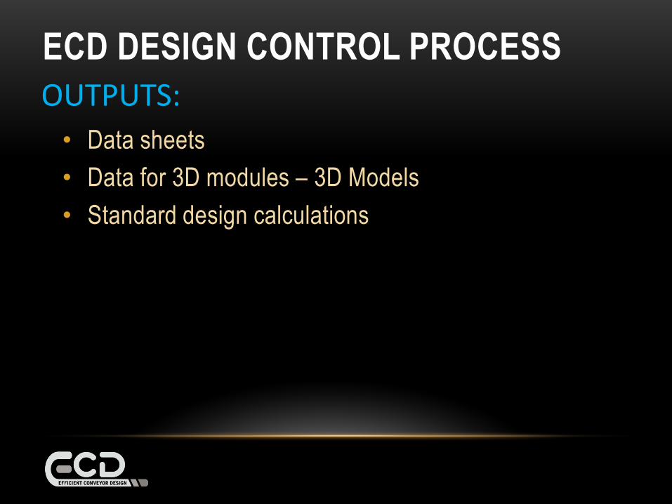
• Data sheets
• Data for 3D modules – 3D Models
• Standard design calculations
OUTPUTS:
ECD DESIGN CONTROL PROCESS

• Data sheets
• Data for 3D modules – 3D Models
• Standard design calculations
• Foundation detail and set-out dimensions are
automatically generated
OUTPUTS:
ECD DESIGN CONTROL PROCESS
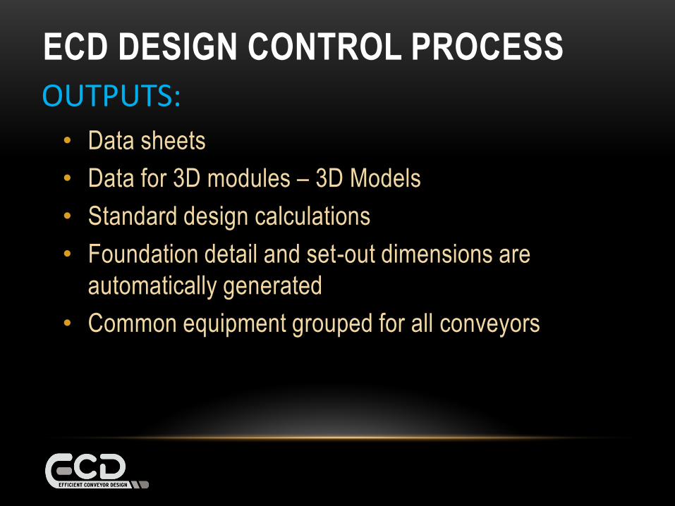
• Data sheets
• Data for 3D modules – 3D Models
• Standard design calculations
• Foundation detail and set-out dimensions are
automatically generated
• Common equipment grouped for all conveyors
OUTPUTS:
ECD DESIGN CONTROL PROCESS
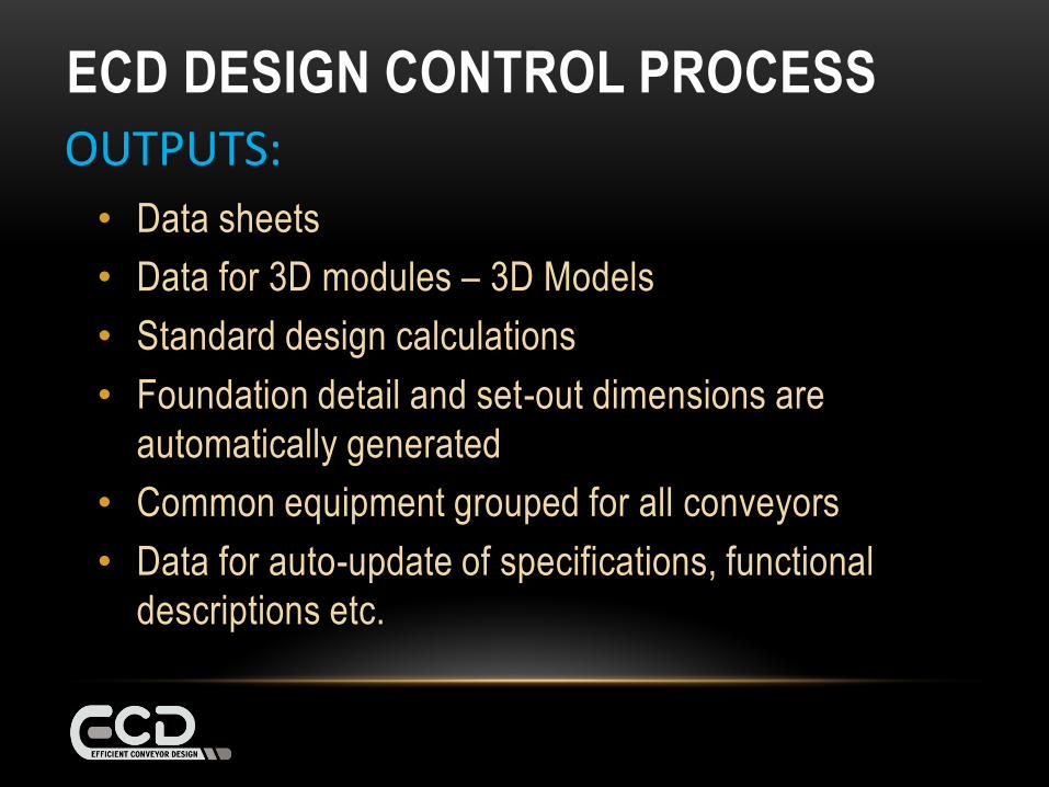
• Data sheets
• Data for 3D modules – 3D Models
• Standard design calculations
• Foundation detail and set-out dimensions are
automatically generated
• Common equipment grouped for all conveyors
• Data for auto-update of specifications, functional
descriptions etc.
OUTPUTS:
ECD DESIGN CONTROL PROCESS

MODULAR
SYSTEM

MODULAR SYSTEM
• Each conveyor is made up of standard modules

MODULAR SYSTEM
• Each conveyor is made up of standard modules
• Arrange in differing combinations
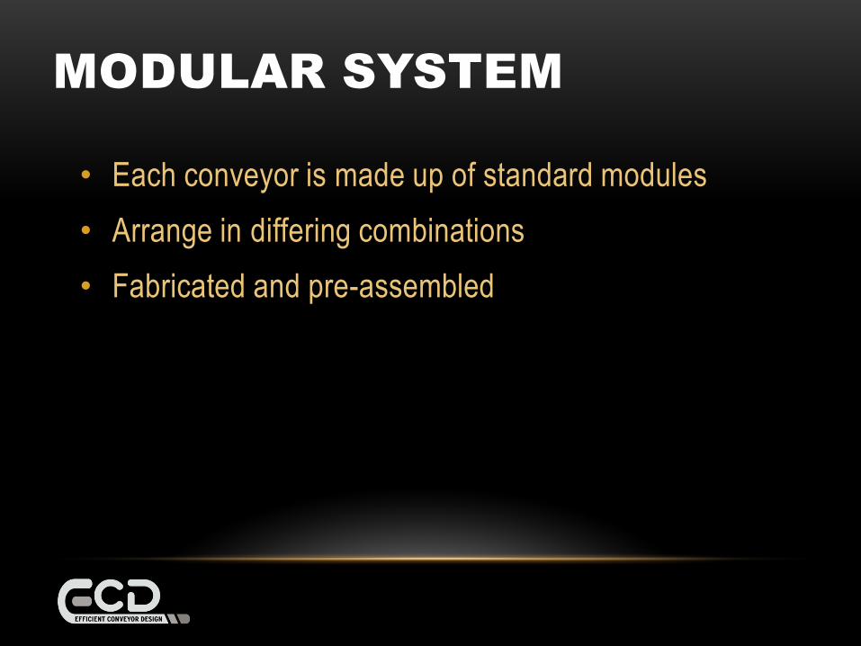
MODULAR SYSTEM
• Each conveyor is made up of standard modules
• Arrange in differing combinations
• Fabricated and pre-assembled
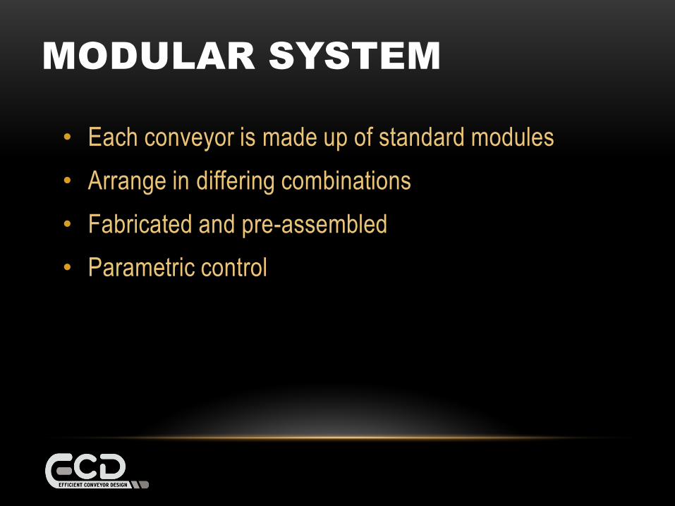
MODULAR SYSTEM
• Each conveyor is made up of standard modules
• Arrange in differing combinations
• Fabricated and pre-assembled
• Parametric control
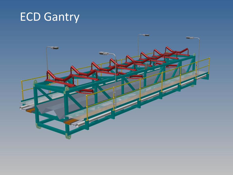
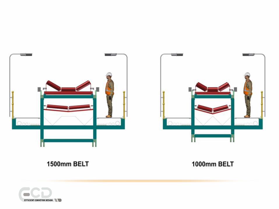
ECD Gantry

ENGINEERING
ENGINEERING
• Each module is structurally pre-engineered
ENGINEERING
• Each module is structurally pre-engineered
• Modules are designed with pre-defined limits

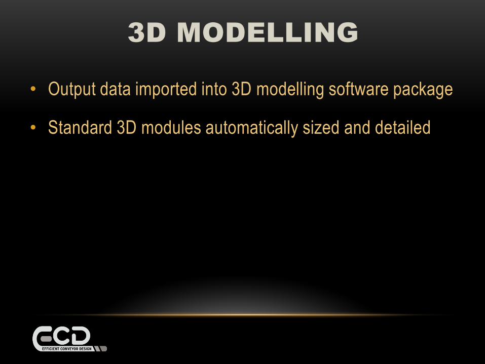
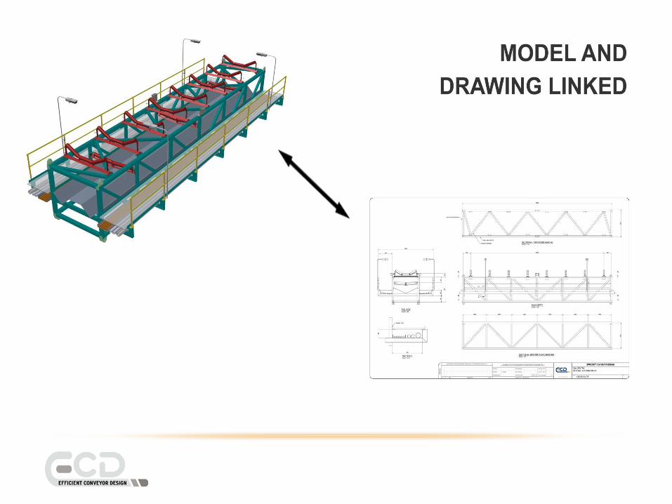
3D MODELLING
3D MODELLING
• Output data imported into 3D modelling software package
3D MODELLING
• Output data imported into 3D modelling software package
• Standard 3D modules automatically sized and detailed
3D MODELLING
• Output data imported into 3D modelling software package
• Standard 3D modules automatically sized and detailed
• Bills of Material, equipment and instrument lists, and
cable schedules automatically produced
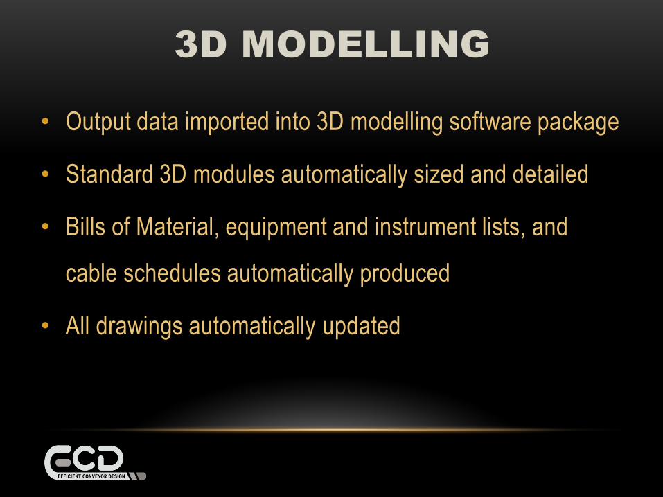
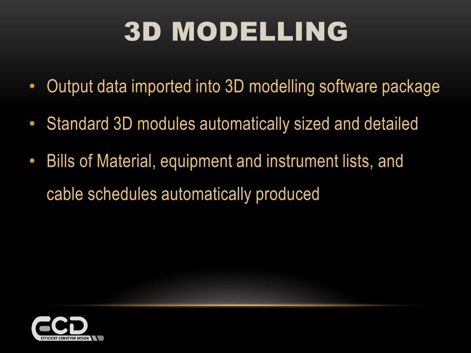
3D MODELLING
• Output data imported into 3D modelling software package
• Standard 3D modules automatically sized and detailed
• Bills of Material, equipment and instrument lists, and
cable schedules automatically produced
• All drawings automatically updated

BENEFITS

BENEFITSReduced

BENEFITSReduced
DESIGN TIME
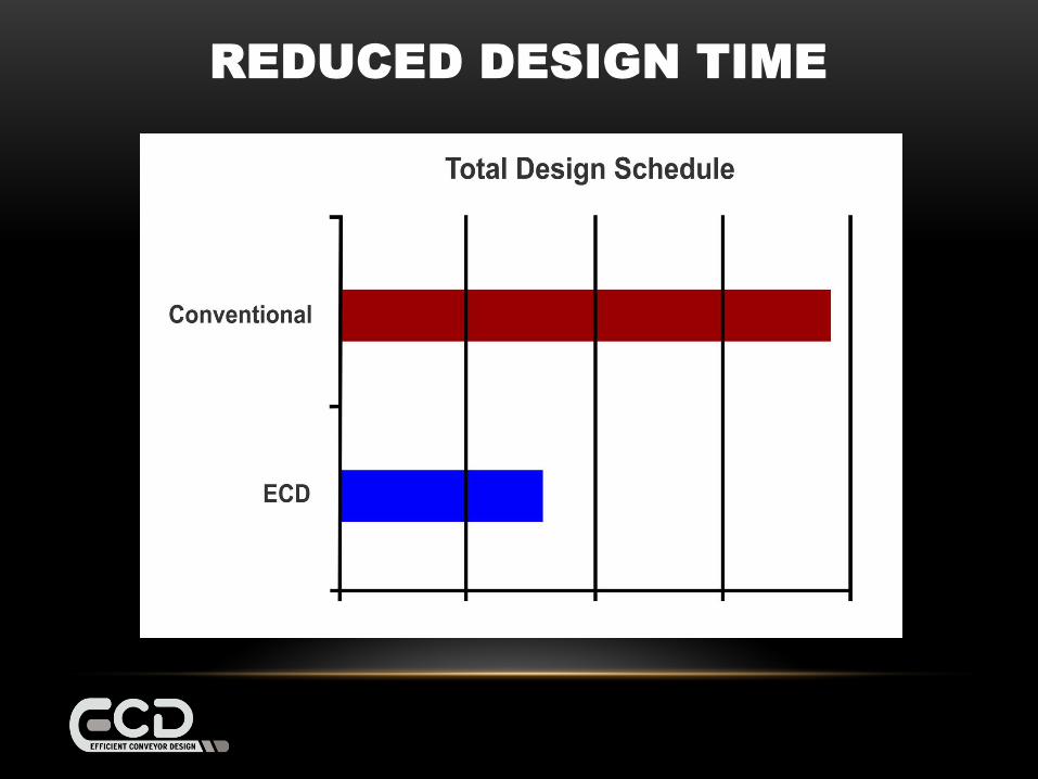
REDUCED DESIGN TIME

BENEFITSReduced
DESIGN TIME
Project Schedule
BENEFITSReduced
DESIGN TIME
Project Schedule
Management Cost
BENEFITSReduced
DESIGN TIME
Project Schedule
Management Costs
CONSTRUCTION TIME

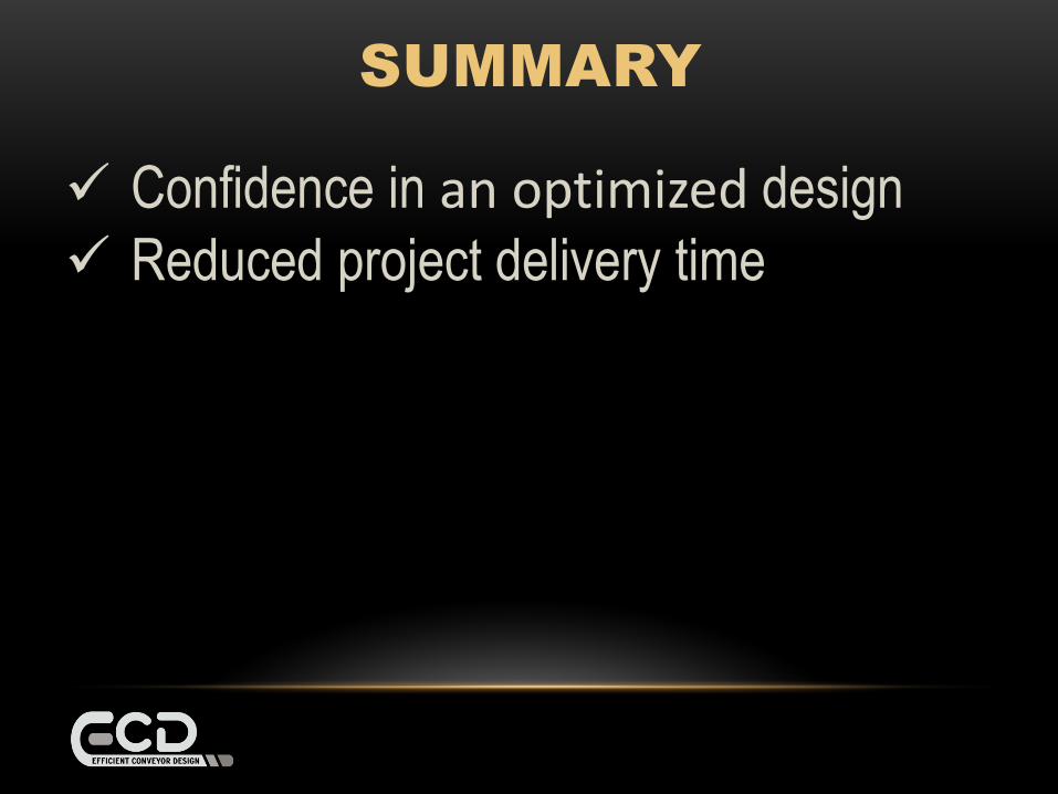
SUMMARY
Confidence in an optimized design
SUMMARY
Confidence in an optimized design
Reduced project delivery time
SUMMARY
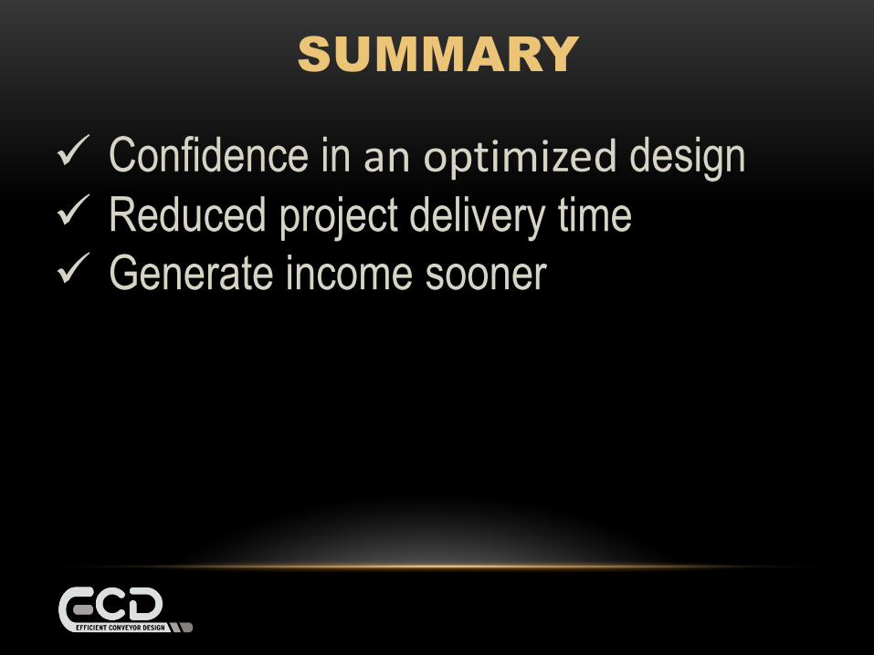
Confidence in an optimized design
Reduced project delivery time
Generate income sooner
SUMMARY
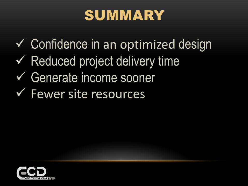
Confidence in an optimized design
Reduced project delivery time
Generate income sooner Fewer site resources
SUMMARY
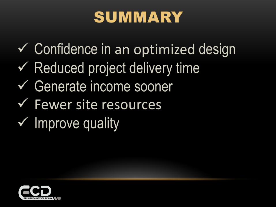
Confidence in an optimized design
Reduced project delivery time
Generate income sooner Fewer site resources Improve quality
SUMMARY
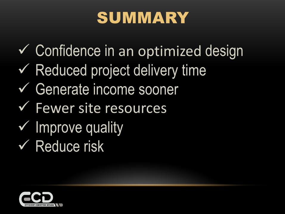
Confidence in an optimized design
Reduced project delivery time
Generate income sooner Fewer site resources Improve quality
Reduce risk
SUMMARY

Conveyors will never be
designed the same way
again!

effcondesign.com
THANK YOU
QUESTIONS?
![Benson Lecture Inpla[1] Phil Benson](https://static.fdocuments.us/doc/165x107/5549e849b4c90518488b4ca4/benson-lecture-inpla1-phil-benson.jpg)