((Marte 03)) El Senor de La Guerra de Marte(c.1) - Edgar Rice Burroughs
HAL Id: inria-00525007https://hal.inria.fr/inria-00525007
Submitted on 10 Oct 2010
HAL is a multi-disciplinary open accessarchive for the deposit and dissemination of sci-entific research documents, whether they are pub-lished or not. The documents may come fromteaching and research institutions in France orabroad, or from public or private research centers.
L’archive ouverte pluridisciplinaire HAL, estdestinée au dépôt et à la diffusion de documentsscientifiques de niveau recherche, publiés ou non,émanant des établissements d’enseignement et derecherche français ou étrangers, des laboratoirespublics ou privés.
MARTE based modeling approach for Partial DynamicReconfigurable FPGAs
Imran Rafiq Quadri, Samy Meftali, Jean-Luc Dekeyser
To cite this version:Imran Rafiq Quadri, Samy Meftali, Jean-Luc Dekeyser. MARTE based modeling approach for Par-tial Dynamic Reconfigurable FPGAs. Sixth IEEE Workshop on Embedded Systems for Real-timeMultimedia (ESTIMedia 2008), Oct 2008, Atlanta, United States. �inria-00525007�

MARTE based modeling approach for PartialDynamic Reconfigurable FPGAs
Imran Rafiq Quadri, Samy Meftali and Jean-Luc Dekeyser,INRIA LILLE NORD EUROPE - LIFL - University of Lille - CNRS, Lille, France
{Imran.Quadri, Samy.Meftali, Jean-Luc.Dekeyser}@lifl.fr
Abstract— As System-on-Chip (SoC) architectures become piv-otal for designing embedded systems, the SoC design complexitycontinues to increase exponentially necessitating the need to findnew design methodologies. In this paper we present a novelSoC co-design methodology based on Model Driven Engineeringusing the MARTE (Modeling and Analysis of Real-time andEmbedded Systems) standard. This methodology is utilized tomodel fine grain reconfigurable architectures such as FPGAsand extends the standard to integrate new features such asPartial Dynamic Reconfiguration supported by modern FPGAs.The goal is to carry out modeling at a high abstraction levelexpressed in UML (Unified Modeling Language) and followingtransformations of these models, automatically generate the codenecessary for FPGA implementation.
I. I NTRODUCTION
Modern System-on-chips (SoCs) have become an integralpart of designing embedded systems for targeting intensiveparallel computation applications. Continuous advances inSoC technology permit to increase the number of hardwareresources on a single chip while in parallel the targetedapplication domains: such as multimedia video codes, softwaredefined radio, radar/sonar detection systems are becomingmore sophisticated leading to a significant gap between designproductivity and verification of these complex systems. An im-portant challenge is to find efficient design methodologies thataddress the issues such as related to expressing parallelism.
Model Driven Engineering [1] (MDE) can be viewed as aHigh Level Design Flowand effectively resolves the variousissues linked with SoC co-design. In a high level synthesis(HLS) flow, the underlying implementation details are usu-ally hidden from the user resulting in advantages such asdecrease in time to market and fabrication costs. However,usually the specifications are written in C/C++ or other textbased languages and concepts such as related to parallelismand hierarchy are not clearly evident making the necessarymodifications and extensions quite difficult. In contrast, inMDE, the system is modeled at a high level allowing severalabstraction levels for different designers each focusing on aparticular domain space. The UML (Unified Modeling Lan-guage) graphical language increases system comprehensibilityand permits relations between concepts defined at differentlevels. Users provide high abstraction level descriptionsoftheir systems and can identify the internal concepts such astask/data parallelism and hierarchy easily. The graphicalnatureof these specifications allows for their reuse, modification,maintenance and extension.
Modern FPGAs support the emerging feature of PartialDynamic Reconfiguration [2] (PDR) allowing specific portionsof FPGA to be reconfigured on the fly, hence time-sharingthe available hardware resources. Moreover, PDR allows taskswapping depending upon the application needs and Quality-Of-Service (QoS) requirements.
MARTE [3] (Modeling and Analysis of Real-Time andEmbedded Systems) is an industry standard of the ObjectManagement Group (OMG) for model-driven development ofembedded systems and for SoC co-design. It provides the ca-pability to model software, hardware and their relations, alongwith extensions for performance and scheduling analysis. Thisstandard while rich in concepts unfortunately lacks certainaspects for FPGA modeling.
GASPARD [4] is a MARTE compliant SoC co-designenvironment dedicated specially towards parallel hardwareand software co-design allowing to move from high levelMARTE specifications to an executable platform. It exploitsthe parallelism included in repetitive constructions of hardwareelements or regular constructions such as application loops.
The contribution of this paper is to present part of acomplete design flow with an extended version of the MARTEstandard for general modeling of FPGAs. Our concepts allowus to introduce PDR in MARTE for modeling all types ofFPGAs supporting this feature. Finally, using the MDE modeltransformations, this methodology can be used to bridge thegap between high abstraction levels and implementation detailsto automatically generate the necessary code required for thegeneration of bitstream(s) for FPGA implementation.
The rest of this paper is organized as follows. Section 2provides an overview of MDE and model transformations.Section 3 describes GASPARD and MARTE. Section 4 gives asummary of related works followed by PDR concepts. Section6 defines our methodology for modeling PDR supportedFPGAs. This paper finishes with a case study in section 7followed by a conclusion.
II. M ODEL DRIVEN ENGINEERING
MDE revolves around three focal concepts.Models, Meta-modelsand Transformations. A model is composed of con-cepts and relations and is an abstraction of reality. Conceptsare “things” and relations are the “links” between these thingsin a real world scenario. A model can be observed fromdifferent point of views (views in MDE). A metamodel isa collective sum of concepts and relations for defining a

model and defines the model syntax as a language defines itsgrammar. Each model is then said toconformto its metamodel.
A model transformation is a compilation process that trans-forms asourcemodel into atarget model allowing to movefrom a higher abstract model to a lower detailed model.The source and target models conform to their respectivemetamodels. A model transformation is based on a set ofrules that identify concepts in a source metamodel in orderto create enriched concepts in the target metamodel. Thisseparation allows to extend and maintain the compilationprocess. Each rule can be independently modified and newrules extend the compilation process. The transformationscarry out refinements moving from high abstraction levels tolow levels for code generation. At each intermediate level,implementation details are added to the compilation process.The advantage of this approach is that it allows to defineseveral model transformations from the same abstraction levelbut targeted to different lower levels, offering opportunities togenerate several implementations from a specification.
III. GASPARD ENVIRONMENT AND MARTE
GASPARD [4] is a MDE based SoC co-design graphicalenvironment and is a subset of the industry approved MARTEstandard. MARTE allows a clearseparation of concernsbe-tween the hardware and the software components which isof pivotal significance in SoC conception. Our environmentuses the MARTE allocation mechanism (Alloc package) thatpermits to link the independent hardware and software models(for e.g. mapping of a task or data onto a processor or amemory respectively). GASPARD also relies heavily upon theRepetitive Structure Modeling (RSM)annex which is based ona MoC (Model of Computation) inspired from ArrayOL [5]that describes the potential parallelism in a system (parallelcomputations in the application software part and parallelstructure of its hardware architecture in a compact manner).GASPARD currently targetscontrol and data flow orientedintensive signal processing (ISP) applications(such as multi-media video codecs, radar/sonar detection applications, highperformance applications). The applications targeted in GAS-PARD are widely encountered in SoC design and respect thesemantics of ArrayOL [5].
GASPARD also benefits from the notion of aDeploymentmodel level [6] that links every elementary component (thebasic building block of all components) to an existing codefacilitating Intellectual Property (IP) reuse. This levelprovidesIP information for model transformations forming a compi-lation chain to transform the high abstraction level models(application, architecture and allocation) for differentdomains(currently GASPARD targets formal verification, simulation,high performance computing and synthesis). This last conceptis currently not present in MARTE and is a potential extensionto allow a flow from high level modeling to automatic codegeneration. We are currently in the process of integrating acontrol aspect [7] with this level which will allow to linkan elementary component with several IPs (several possibleimplementations) and afterwards via model transformationsconvert this control aspect into the state machine code to
be implemented in the reconfigurable controller in the FPGAautomatizing part of the reconfiguration management.
IV. RELATED WORKS
ROSES [8] is a Multiprocessor SoC (MPSoC) specificationand design environment but with a disadvantage as it doesnot conform to MDE concepts and as compared to GAS-PARD, starts from a low level description equivalent to ourdeployment level. In contrast, [9] uses the MDE approach forthe design of a Software Defined Radio (SDR), but does notutilize the MARTE standard as proposed by OMG. Whileworks such as [10] are focused on generating VHDL fromUML state machines, they fail to integrate the MDE conceptsfor HW/SW co-design and are not capable to manage ISPapplications. MILAN [11] is another MDE based project forSoC co-design but is not MARTE compliant. Only [12] comesclose to our intended methodology by using the MDE conceptsfor creation of hardware accelerators. However the MARTElayer is absent and the reconfiguration is carried out in a staticmanner and there is no notion of PDR. While there are lotsof related tools, works and projects; we have only detailedsome and have not given an exhaustive summary. Also wehave not included here the works specifically related to PDRwhich we have previously detailed in [13]. To the best ofour knowledge, only our methodology takes into account thefour domain spaces: SoC co-design, MDE, MARTE and PDRwhich is the novelty of our design flow.
V. BASIC PDR RELATED CONCEPTS
Currently only Xilinx FPGAs support PDR. Xilinx initiallyproposed two methodologies followed by theEarly AccessPartial Reconfiguration (EAPR)[14] flow. Bus macrosare usedto ensure the proper routing between the static and dynamicparts before and after reconfiguration. TheInternal Reconfig-uration Access Port (ICAP)[15] is present in nearly all XilinxFPGAs and permits to read/write the FPGA configurationmemory at run-time. In combination with the ICAP and thecharacteristics ofglitchless dynamic reconfigurationsupportedby Xilinx FPGAs, aReconfiguration controller(PowerPC orMicroblaze) can be placed inside the FPGA to build a selfcontrolling dynamically reconfigurable system.
VI. M ODELING OF PARTIAL DYNAMIC RECONFIGURABLE
FPGAS
We first present the design flow to model and implementPDR supported FPGAs (Figure.1) which is an extension of theworks presented in [12] (addition of MARTE layer, controlat deployment level and the aspects of PDR). In this paperwe only present the first model level of this flow (modelingof application, architecture and the allocation). Using modeltransformations, we will extend our work to link each modeledcomponent with IP(s) at the Deployment model level (level2). Afterwards, the RTL model level will provide detailedmodeling information for the concepts modeled at level 1and 2 such as the reconfiguration controller and reconfigurablehardware accelerator. Each of these model levels correspondto their respective metamodels. Finally, from the RTL level

we will be able to automatically generate the code for theFSM part of the Reconfiguration controller (to be implementedin a processor) and the reconfigurable portion (level 4). Thiswill allow the creation of bitstreams for FPGA implementationusing commercial tools and the usual synthesis design flows.An important restriction of our flow is that we have to adhereto the Xilinx technologies as currently only Xilinx FPGAssupports the PDR feature. While many extensions and PDRmethodologies exist, we have chosen to respect the XilinxEAPR flow as it is openly available and flexible enough tobe modified for other PDR methodologies.
Application, Architecture and Allocation Model
at High Abstraction Level
RTL Model
(Reconfigurable Hardware Accelerator,
Controller etc.)
Model Transformation
Transformation for code
1
2
3
Deployment Model
Model Transformation
4 Code Generation + Placement
Fig. 1. The complete design flow
A. Basic MARTE Hardware concepts
In MARTE, The basic hardware concepts are presented inthe Hardware Resource Model (HRM). HRM can be viewedin different manners, either a functional view (HwLogical subpackage), a physical view (HwPhysical sub package) or amerge of the two. These two subpackages derive from a rootpackage calledHwGeneral that revolves around the conceptof a HwResourcewhich defines a generic MARTE hardwareentity that can be composed of other HwResource(s). Thisconcept is then further enriched according to the functional orphysical specifications. The functional view defines hardwareresources as eithercomputing, storage, communication, timingor device resources. The physical view represents hardwareresources as physical components with details about theirshape, size and power consumption among other attributes.Currently GASPARD supports only the logical view but wehave integrated both the physical and merged views in theframework for modeling PDR featured architectures. TheHRM also exploits the Non-Functional Properties (NFP) pack-age of MARTE. This package introduces an accurate valuespecification language for supporting complex expressionsforspecifying non-functional properties as well as quantitativeannotations with measurement units.
B. MARTE modifications for PDR concepts
We first examined the HRM package of MARTE andfound it to be lacking in certain aspects. TheHwComputingsubpackage in the HRM functional view defines a set of activeprocessing resources central for an execution platform. AHw-ComputingResourcesymbolizes an active processing resourcethat can be specialized as either a processor (HwProcessor), anASIC (HwASIC) or a PLD (HwPLD). An FPGA is representedby the HwPLD stereotype, it can contain a RAM memory(HwRAM) (as well as other HwResources) and is characterized
by a technology (SRAM, Antifuse etc.). The cell organizationof the FPGA is characterized by the number of rows andcolumns, but also by the type of architecture (Symmetricalarray, row based etc.). These concepts are sufficient enoughforan abstract FPGA description. However the concepts relatedto representing a processor are not sufficient for a complexSoC design in which a processor can either be implementedas a softcore IP or integrated as a hardcore IP. We thus add theattributeimtype (ImplementationType) that is flexible enoughto define a processor implementation as eitherHardcore orSoftcore and adaptable with future evolution using theOtherand Undefined types. Figure.2 shows only the simplifiedmodeling description of the modified HwComputing sub-package related to a processor implementation.
Fig. 2. Modified version of the HwProcessor concept
The second modification relates to the physical (HwLay-out) package that revolves around theHwComponentconceptwhich is an abstraction of any real hardware entity based on itsphysical attributes. HwComponent can be specialized as eitherHwChip (e.g. a processor),HwChannel(e.g a bus),HwPort(e.g. an interface),HwCard (e.g. a motherboard) or aHwUnit(a hardware resource that does not fall into the precedingfour categories). In order to specify the nature of the areafor a PDR featured architecture (either static or dynamicallyreconfigurable), we have introduced the attributeareatype(Areatype) which can be eitherStatic, DynamicReconf ortyped asOther to adapt to future evolution. Although thisconcept can be implemented as a functional property, we havechosen to implement it in the physical view. Figure.3 shows thesimplified overview of our modified HwComponent concept.
Fig. 3. Modified version of the HwComponent concept
These are the 2 general concepts that we have introducedat the specification level of the MARTE standard and couldgenerally benefit other frameworks and methodologies and canbe extended. We now present the specific concepts related toFPGA and PDR in our methodology.
We then present a example of a classical PDR supportedXilinx FPGA. We have taken the Virtex-II Pro on a XUPBoard (as shown in figure.4) as a reference as it is a popularchoice for implementing PDR. The architecture consists of aReconfiguration Controller (a PowerPC in this case) connected

to a 64-bit PLB bus and communicates with the slower slaveperipherals (connected to the 32-bit OPB bus) via a PLB toOPB Bridge. The peripherals connected to the OPB bus aredetailed as follows. A SystemACE controller for accessing thepartial bitstreams placed in an external onboard Compact Flash(CF) card. A SDRAM controller for a DDR SDRAM presentonboard that permits the partial bitstreams to be preloadedfrom the CF during initialization. An ICAP is present inthe form of an OPB peripheral (OPBHwICAP) permittingpartial reconfiguration using the read-modify-write mechanism[15]. This static portion is connected to a ReconfigurableHardware Accelerator (RHA) via bus macros. Also it wasan implementation choice to connect the RHA with the OPBbus. The concepts such as PowerPC, PLB and OPB buses,PLB to OPB Bridge, CF and SDRAM memories can beeasily explained using the current MARTE HRM concepts.However the peripherals, bus macros, ICAP and RHA requirean extended and more detailed conception.
PowerPC
(Reconfiguration
Controller)
PLB
To
OPB Bridge SystemACE
Controller
SDRAM
Controller
OPB
HwICAP
Partial
Reconfigurable
Region
(containing
a Hardware
Accelerator)
PLB
Bus
OPB
Bus
External
Compact
Flash Memory
SDRAM
Static AreaBus Macro(s)
Fig. 4. Block Diagram of the architecture of our reconfigurable system
The HwCommunicationsubpackage in the HRM functionalview defines the basic concepts for hardware communication.HwMedia is the central concept defining a communicationresource capable of data transfer with a theoretical bandwidth.It can be controlled by aHwArbiter and connected to otherHwMedia(s) by means of aHwBridge. A HwEndpointdefinesa connection point of a HwResource and can be defined asan interface (e.g. pin or port).HwBus illustrates a specificwired channel with particular functional attributes. Theseconcepts are sufficient and abstract enough to define all kindofcommunication resources. Some of the other common HRMconcepts that we utilize areHwComputingResource(to de-scribe a general computing resource) from theHwComputingpackage,HwRAMandHwROM from theHwMemorypackage(for RAM and ROM concepts),HwStorageManagerfromthe HwStorageManagerpackage (for a memory controller),HwClock from theHwTimingpackage (to specify a clock andHwIO from theHwIO package (for an I/O resource).
Xilinx provides the notion of an Intellectual Property Inter-face (IPIF) which is a hardware bus wrapper specially designedto ease IP core interfacing with the IBM Coreconnect bus. Asall peripherals in our architecture consist of the IPIF wrapperand an IP core, this is a vital modeling concept. The IPIFhas two basic attributes: amode which can be eitherMaster,Slaveor Master/Slave, andtype that determines the protocolof IPIF adapted for a particular bus. It can be eitherPLB, OPBor extensible usingOther or Undefined types. We avoidedadding detailed information related to the protocols offeredby IPIF to simplify its definition at the high abstraction level.
The IPIF itself is typedHwEndpoint to denote that it is ahardware wrapper providing an interface to the IP core. Wethus add the notion of a hardware wrapper using MARTE.Figure.5 shows the modeling of the IPIF.
Fig. 5. Modeling of the IPIF hardware wrapper
Fig. 6. Modeling of a Bus macro
The second modeling concept is that of Bus Macros (BMs).Although the EAPR flow now allows signals in the basedesign to pass through the reconfigurable regions without theuse of bus macros, they are still essential in order to ensurethe correct routing between the static and dynamic regions.They are CLB based in nature and provide a unidirectional8-bit data transfer. Figure.6 shows the modeling of a BusMacro (Busmacro) having four attributes. Thesigdir attributedetermines the direction of communication which can beLeft2Right or Right2Left (for Virtex-II and Virtex-II Prodevices), as well asTop2Bottom, Bottom2Top or Otherfor Virtex-IV and other future PDR supported devices. Thewidth attribute determines the CLB width of the bus macro(2CLBs or 4CLBs width making it either a narrow or widebus macro or use ofOther for a user specified width).The Synchronous attribute determines if the bus macro issynchronous or not. We have assigned a default value oftrue to this attribute (as recommended by Xilinx). The finalattributedevice determines the targeted FPGA device family(either Virtex-II Pro , Virtex-II , Virtex-4 or a newer devicesuch as Virtex-5 using theOther type). The Bus Macro istypedHwEndpointin order to illustrate that it is an interface.
We then carry out modeling of the OPBHWICAP periph-eral. It consists of an IPIF (ic2opb) connected to the HWICAPcore (hwicap) (typed asHwComputingResource) and is itselfdefined as aHwComputingResource. The HWICAP core isitself composed of three components: an ICAP controller(icapctrl ) and ICAP Primitive (icap) both typed asHw-ComputingResource(s) and a BlockRAM (bram) defined asHwRAM for stocking a configuration frame of FPGA memory.The BlockRAM contains a port having a multiplicity of 2 in-dicating that it is repeated two times. TheReshapeconnectors(as defined in the MARTE RSM package) are used in order tolink the sub components of the HWICAP. The Reshape allowsto represent complex link topologies in a simplified manner.Here, the Reshape connectors permits to specify accurately

which port (either the port of the ICAPController or thesingle port of the HWICAP itself) is connected to whichrepetition of the BlockRAM port as shown in figure.7. Also,the sub components of HWICAP have specific attributes (e.g.BlockRAM has 16Kbits memory) related to implementationdetails. We refer the reader to [15] for a detailed descriptionof the HWICAP core.
Fig. 7. Modeling of the OPB HWICAP Peripheral
Fig. 8. A Reconfigurable Hardware Accelerator
Figure.8 illustrates the modeling of the ReconfigurableHardware Accelerator (RHA). The PRR (Partial reconfigurableregion) consists of a RHA (HwAcc) typed asHwPLD havingports AccessOutand AccessInand an IPIF (Acc2opb). ThePRR itself is of theHwResourcetype. The RHA is typed asHwPLD as it is reconfigurable, as compared to a typical hard-ware accelerator which can be seen as aHwASICdependingupon the designer’s point of view.
Figure.9 finally illustrates our reconfigurable architecture (aXC2VP30 Virtex-II Pro chip) utilizing our proposed conceptsin a merged functional/physical view. Each of the hardwarecomponents has two type definitions (the first represent-ing the functional and the second representing the physicalone). The XC2VP30 chip consists of a PowerPC PPC405(ppc 0) connected via a PLB bus (plb) to the slave periph-erals: the OPBHWICAP (opbhwicap), the OPBSysAceCtrl(opbsysac ctr ), the OPBSDRAMCtrl (opbsdram ctr ) andthe PRR (prr ) via the OPB bus (opb). The PLB2OPBBridge(plb2opb) connects the two buses, while Busmacro(s) (bm1andbm0 having types Left2Right and Right2Left respectively)connect the OPB bus to the PRR. Each of the busmacrosare instantiated twice as indicated by the multiplicity of 2on both bm0 and bm1 respectively. Also the OPB bus hasa slavea port with a multiplicity of 3 which allows the busto connect to the peripherals (opbsysac ctr, opbsdramctr andopbhwicap), we have used Reshape connectors to determine
which peripheral is connected to which repetition of the slaveport. Similarly we have used Reshape connectors to determinethe accurate connections between the bus macros and the portsof OPB and PRR. Although we could have used a single slaveport on OPB with an appropriate multiplicity to include thetopology of bus macros, this is avoided in order to reducethe design complexity. Finally, the XC2VP30 contains twoHwEndPoint(s) interfaces,toCompactFlash and toSDRAMto connectopbsysac ctr and opbsdram ctr to the compactflash and the SDRAM memories respectively. The Attributesintroduced by us and those by default in MARTE allow thedesigner to specify general attributes of each component atthe highest abstraction level (e.g. ppc0 having a frequencyof 300 MHz). While the MARTE modifications and the PDRmodeling may seem trivial, however this is done explicitlyin order to elevate the abstraction levels and decrease theimplementation details at these higher levels.
Fig. 9. Modeling of our PDR Architecture
VII. C ASE STUDY
Fig. 10. Model of an Image Filter task
A case study of a complete SoC model is presented hereto illustrate our methodology. We present here only a simpleimage filter application, however other multimedia applica-tions such as H.263 encoder [6] can be implemented usingGASPARD and our design flow. The modeled applicationMainApplication is an academic grayscale 4x4 pixel imagefilter application (producing 8-bit images). It consists ofthree
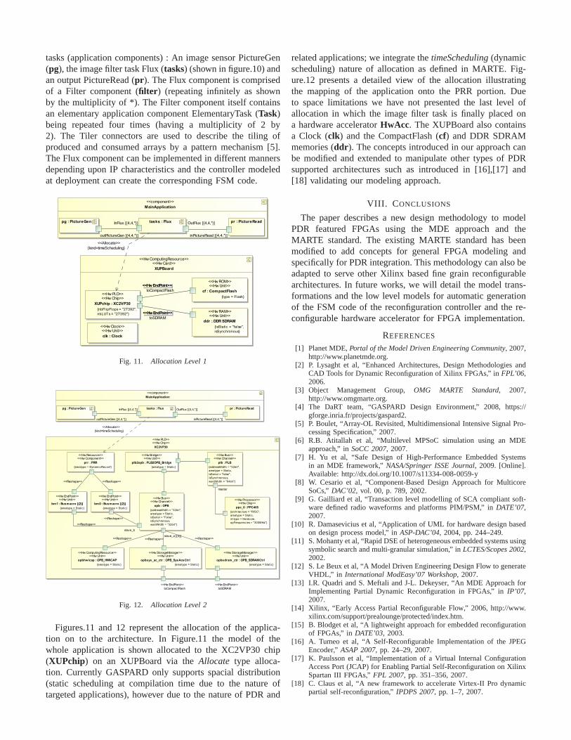
tasks (application components) : An image sensor PictureGen(pg), the image filter task Flux (tasks) (shown in figure.10) andan output PictureRead (pr ). The Flux component is comprisedof a Filter component (filter ) (repeating infinitely as shownby the multiplicity of *). The Filter component itself containsan elementary application component ElementaryTask (Task)being repeated four times (having a multiplicity of 2 by2). The Tiler connectors are used to describe the tiling ofproduced and consumed arrays by a pattern mechanism [5].The Flux component can be implemented in different mannersdepending upon IP characteristics and the controller modeledat deployment can create the corresponding FSM code.
Fig. 11. Allocation Level 1
Fig. 12. Allocation Level 2
Figures.11 and 12 represent the allocation of the applica-tion on to the architecture. In Figure.11 the model of thewhole application is shown allocated to the XC2VP30 chip(XUPchip) on an XUPBoard via theAllocate type alloca-tion. Currently GASPARD only supports spacial distribution(static scheduling at compilation time due to the nature oftargeted applications), however due to the nature of PDR and
related applications; we integrate thetimeScheduling(dynamicscheduling) nature of allocation as defined in MARTE. Fig-ure.12 presents a detailed view of the allocation illustratingthe mapping of the application onto the PRR portion. Dueto space limitations we have not presented the last level ofallocation in which the image filter task is finally placed ona hardware acceleratorHwAcc. The XUPBoard also containsa Clock (clk) and the CompactFlash (cf) and DDR SDRAMmemories (ddr ). The concepts introduced in our approach canbe modified and extended to manipulate other types of PDRsupported architectures such as introduced in [16],[17] and[18] validating our modeling approach.
VIII. C ONCLUSIONS
The paper describes a new design methodology to modelPDR featured FPGAs using the MDE approach and theMARTE standard. The existing MARTE standard has beenmodified to add concepts for general FPGA modeling andspecifically for PDR integration. This methodology can alsobeadapted to serve other Xilinx based fine grain reconfigurablearchitectures. In future works, we will detail the model trans-formations and the low level models for automatic generationof the FSM code of the reconfiguration controller and the re-configurable hardware accelerator for FPGA implementation.
REFERENCES
[1] Planet MDE,Portal of the Model Driven Engineering Community, 2007,http://www.planetmde.org.
[2] P. Lysaght et al, “Enhanced Architectures, Design Methodologies andCAD Tools for Dynamic Reconfiguration of Xilinx FPGAs,” inFPL’06,2006.
[3] Object Management Group,OMG MARTE Standard, 2007,http://www.omgmarte.org.
[4] The DaRT team, “GASPARD Design Environment,” 2008, https://gforge.inria.fr/projects/gaspard2.
[5] P. Boulet, “Array-OL Revisited, Multidimensional Intensive Signal Pro-cessing Specification,” 2007.
[6] R.B. Atitallah et al, “Multilevel MPSoC simulation usingan MDEapproach,” inSoCC 2007, 2007.
[7] H. Yu et al, “Safe Design of High-Performance Embedded Systemsin an MDE framework,”NASA/Springer ISSE Journal, 2009. [Online].Available: http://dx.doi.org/10.1007/s11334-008-0059-y
[8] W. Cesario et al, “Component-Based Design Approach for MulticoreSoCs,”DAC’02, vol. 00, p. 789, 2002.
[9] G. Gailliard et al, “Transaction level modelling of SCA compliant soft-ware defined radio waveforms and platforms PIM/PSM,” inDATE’07,2007.
[10] R. Damasevicius et al, “Application of UML for hardware design basedon design process model,” inASP-DAC’04, 2004, pp. 244–249.
[11] S. Mohanty et al, “Rapid DSE of heterogeneous embedded systems usingsymbolic search and multi-granular simulation,” inLCTES/Scopes 2002,2002.
[12] S. Le Beux et al, “A Model Driven Engineering Design Flowto generateVHDL,” in International ModEasy’07 Workshop, 2007.
[13] I.R. Quadri and S. Meftali and J-L. Dekeyser, “An MDE Approach forImplementing Partial Dynamic Reconfiguration in FPGAs,” inIP’07,2007.
[14] Xilinx, “Early Access Partial Reconfigurable Flow,” 2006, http://www.xilinx.com/support/prealounge/protected/index.htm.
[15] B. Blodget et al, “A lightweight approach for embedded reconfigurationof FPGAs,” in DATE’03, 2003.
[16] A. Tumeo et al, “A Self-Reconfigurable Implementation of the JPEGEncoder,”ASAP 2007, pp. 24–29, 2007.
[17] K. Paulsson et al, “Implementation of a Virtual Internal ConfigurationAccess Port (JCAP) for Enabling Partial Self-Reconfiguration on XilinxSpartan III FPGAs,”FPL 2007, pp. 351–356, 2007.
[18] C. Claus et al, “A new framework to accelerate Virtex-II Pro dynamicpartial self-reconfiguration,”IPDPS 2007, pp. 1–7, 2007.