
Mars Reconnaissance Orbiter Telecommunications
76
description
DESCANSO Design and Performance Summary Series
Transcript of Mars Reconnaissance Orbiter Telecommunications


DESCANSO Design and Performance Summary Series
Article 12
Mars Reconnaissance Orbiter
Telecommunications
Jim Taylor Dennis K. Lee Shervin Shambayati Jet Propulsion Laboratory
California Institute of Technology
Pasadena, California
National Aeronautics and
Space Administration
Jet Propulsion Laboratory
California Institute of Technology
Pasadena, California
September 2006

This research was carried out at the Jet Propulsion Laboratory, California Institute of Technology,
under a contract with the National Aeronautics and Space Administration.

iii
Prologue
Mars Reconnaissance Orbiter
The cover image is an artist’s rendition of the Mars Reconnaissance Orbiter (MRO) as its
orbit carries it over the Martian pole. The large, articulated, circularly shaped high-gain antenna
above the two articulated paddle-shaped solar panels points at the Earth as the solar panels point
toward the Sun. This antenna is the most noticeable feature of the communications system,
providing a link for receiving commands from the Deep Space Stations on the Earth and for
sending science and engineering information to the stations. The antenna is larger than on any
previous deep-space mission, and the amplifiers that send the data on two frequencies are also
more powerful than previously used in deep space.
Included in the command data and the science data is information that the orbiter relays
to and from vehicles on the surface as it passes over them. The orbiter uses the Electra
transceiver and a smaller low-gain antenna for this communication. The antenna is the smaller.
gold-colored cylinder pointed toward the surface. The transceiver is the first Electra flown, and it
has the capability to communicate efficiently with surface vehicles such as Phoenix and Mars
Science Laboratory.
By necessity, this article is a prologue, as it was completed just after the orbiter
successfully went into orbit around Mars and began reducing orbit altitude and circularizing the
orbit in preparation for the science mission. The orbit changing was accomplished through a
process called aerobraking, in preparation for the beginning of two years of science starting in
November 2006, followed by two years with the emphasis on relaying data with surface vehicles
starting in November 2008.
To indicate the communications data volume anticipated, the image below is a mosaic of
the ground covered in the first image of Mars taken by the High Resolution Imaging Science
Experiment (HiRISE) camera. The full product was 20,000 pixels wide by 9,500 pixels high for
a total of about 50 gigabits (Gb) of data. It took about 11 hours for MRO to downlink the data to
the Deep Space Network at an effective rate of about 1.3 megabits per second (Mbps).

iv
DESCANSO DESIGN AND PERFORMANCE SUMMARY SERIES
Issued by the Deep Space Communications and Navigation Systems
Center of Excellence
Jet Propulsion Laboratory
California Institute of Technology
Joseph H. Yuen, Editor-in-Chief
Previously Published Articles in This Series
Article 1—“Mars Global Surveyor Telecommunications”
Jim Taylor, Kar-Ming Cheung, and Chao-Jen Wong
Article 2—“Deep Space 1 Telecommunications”
Jim Taylor, Michela Muñoz Fernández, Ana I. Bolea Alamañac, and Kar-Ming Cheung
Article 3—“Cassini Orbiter/Huygens Probe Telecommunications”
Jim Taylor, Laura Sakamoto, and Chao-Jen Wong
Article 4—“Voyager Telecommunications”
Roger Ludwig and Jim Taylor
Article 5—“Galileo Telecommunications”
Jim Taylor, Kar-Ming Cheung, and Dongae Seo
Article 6—“Odyssey Telecommunications”
Andre Makovsky, Andrea Barbieri, and Ramona Tung
Article 7—“Deep Space 1 Navigation: Extended Missions”
Brian Kennedy, Shyam Bhaskaran, J. Edmund Riedel, and Mike Wang
Article 8—“Deep Space 1 Navigation: Primary Mission”
Brian Kennedy, J. Edmund Riedel, Shyam Bhaskaran, Shailen Desai, Don Han, Tim McElrath,
George Null, Mark Ryne, Steve Synnott, Mike Wang, and Robert Werner
Article 9—“Deep Impact Flyby and Impactor Telecommunications”
Jim Taylor and David Hansen
Article 10—“Mars Exploration Rover Telecommunications”
Jim Taylor, Andre Makovsky, Andrea Barbieri, Ramona Tung, Polly Estabrook, and
A. Gail Thomas
Article 11—“Mars Exploration Rover Navigation”
Louis A. D’Amario
v
Table of Contents
Foreword....................................................................................................................................ix
Preface........................................................................................................................................x
Acknowledgements ....................................................................................................................xi
Section 1 Mission Phases and Orbit Summary........................................................................1
1.1 Mission Objectives......................................................................................1
1.2 The MRO Spacecraft...................................................................................1
1.3 Mission Phases............................................................................................3
1.3.1 Launch..........................................................................................3
1.3.2 Cruise ...........................................................................................3
1.3.3 Approach and Mars Orbit Insertion ...............................................4
1.3.4 Aerobraking..................................................................................4
1.3.5 Primary Science Mission...............................................................5
1.3.6 Relay Mission ...............................................................................6
1.3.7 Safe Mode.....................................................................................7
1.4 The MRO Orbit and Its Relay Coverage for Surface Vehicles .....................8
1.5 MRO Orbit Phasing to Support Landing Vehicle EDL ..............................11
Section 2 Telecommunications Subsystem Overview ...........................................................12
2.1 X-Band: Cruise and Orbital Operations .....................................................12
2.1.1 High-Gain Antenna.....................................................................15
2.1.2 Low-Gain Antenna......................................................................17
2.1.3 Transponders ..............................................................................18
2.1.4 RF Amplifiers.............................................................................19
2.2 UHF: Proximity Relay Communications ...................................................21
2.2.1 Proximity-1 Data ........................................................................28
2.2.2 Time Stamp Packets....................................................................28
2.2.3 Raw Data ....................................................................................28
2.2.4 Phase and Power Data.................................................................28
2.2.5 Open-Loop Data .........................................................................28
2.3 Ka-Band: Operational Demonstration........................................................28
Section 3 Ground Data System.............................................................................................30
3.1 Deep Space Network.................................................................................30
3.2 Ka-Band Demonstration Requirements......................................................30
3.3 Ground Data Network Flow for Relay Through Electra.............................31
Section 4 X-Band Telecom Operations.................................................................................34
4.1 Cruise Calibrations....................................................................................34
4.2 MOI Telecom Configurations....................................................................34
4.3 Aerobraking Telecom Configurations........................................................35

vi
4.4 Downlink Telemetry Modulation and Coding............................................35
4.4.1 Short Frame Concatenated (Table 4-2)........................................36
4.4.2 Long Frame Concatenated (Table 4-3) ........................................36
4.4.3 Turbo Code (Tables 4-4 Through 4-6).........................................37
4.4.4 RS-Only (Table 4-7) ...................................................................38
4.5 X-Band Link Performance Summaries ......................................................39
4.6 Coordinating MRO and MER X-Band Operations.....................................42
Section 5 Ka-Band Operational Demonstration ....................................................................45
5.1 Ka-Band Operational Demonstration Overview.........................................45
5.2 Ka-Band Link Prediction and Performance During Cruise.........................45
5.3 Spacecraft Constraints and Operational Factors.........................................47
5.4 Cruise Delta-DOR Operations and Performance........................................49
5.5 Nominal Ka-Band Link Operation During the Science Mission .................50
5.6 Solar Conjunction Experiments .................................................................51
Section 6 UHF Calibrations and Operations .........................................................................52
6.1 UHF System Tests During Cruise..............................................................52
6.2 Phoenix Support........................................................................................52
6.3 Mars Science Laboratory (MSL) Support ..................................................53
Section 7 Lessons Learned ...................................................................................................55
7.1 X-Band .....................................................................................................55
7.2 Ka-Band....................................................................................................55
7.3 UHF..........................................................................................................56
References ................................................................................................................................57
Abbreviations and Acronyms ....................................................................................................59
List of Figures
Figure 1-1. Sketch of the MRO spacecraft with coordinate directions.....................................2
Figure 1-2. Mars-to-Earth range during the primary science phase. ........................................5
Figure 1-3. A typical sequence of activities during a relay session..........................................7
Figure 1-4. Maximum, average, and minimum number of contacts per sol versus latitude of
the lander for MRO orbit......................................................................................9
Figure 1-5. Maximum (top) and average (bottom) pass duration versus Mars latitude for
MRO orbit .........................................................................................................10
Figure 1-6. Maximum gap between potential MRO contacts versus Mars latitude. ...............10
Figure 2-1. MRO Telecom Subsystem block diagram...........................................................13

vii
Figure 2-2. HGA X-band transmit and receive pointing loss relative to boresight .................16
Figure 2-3. HGA Ka-band transmit pointing loss relative to boresight..................................16
Figure 2-4. LGA X-band receive and transmit pointing loss relative to boresight .................17
Figure 2-5. Layout of microwave components in the TWTA panel.......................................20
Figure 2-6. MRO Electra payload operations concept...........................................................22
Figure 2-7. MRO/Electra UHF block diagram and interfaces with C&DH and SSR .............22
Figure 2-8. Electra UHF transceiver (EUT) assembly...........................................................23
Figure 2-9. Electra transceiver block diagram.......................................................................24
Figure 2-10. MRO 437.1-MHz gain pattern............................................................................27
Figure 2-11. MRO 401.6-MHz gain pattern............................................................................27
Figure 3-1. MRO Electra science data flow ..........................................................................32
Figure 3-2. Electra relay pass product output from GDS.......................................................33
Figure 3-3. Electra relay data product from GDS..................................................................33
Figure 4-1. Station elevation angles on MOI day (exit occultation 22:16 UTC) ....................35
Figure 4-2. X-band HGA uplink Pt /N0 profile and command supportability.........................40
Figure 4-3. X-band LGA1 uplink Pt /N0 profile and command supportability .......................40
Figure 4-4. X-band HGA downlink Pt /N0 profile and telemetry supportability.....................41
Figure 4-5. X-band LGA1 downlink Pt /N0 profile and telemetry supportability ...................41
Figure 4-6. MRO uplink keep out window (MUKOW) timing .............................................43
Figure 5-1. Ka-band HGA downlink Pt /N0 profile and telemetry capability .........................46
Figure 5-2. Comparison of Ka-band and X-band telemetry (DSS 34, December 26, 2005) ...47
List of Tables
Table 1-1. Orbit elements for MRO and Odyssey..................................................................9
Table 2-1. MRO telecom mass and power summary............................................................14
Table 2-2. LGA and HGA antenna link parameters. ............................................................18
Table 2-3. SDST link configuration and performance parameters........................................20
Table 2-4. MRO/Electra modes, functions, and performance...............................................25
Table 2-5. CCSDS Prox-1 “Blue Book” channel numbers and “preset” Electra
frequencies.........................................................................................................26
Table 4-1. Telecom cruise calibrations................................................................................34
Table 4-2. Emergency mode (7,1/2) + RS (short frame) concatenated code.........................36

viii
Table 4-3. (7,1/2) + RS (long frame) concatenated code......................................................37
Table 4-4. Turbo code, rate 1/2 ...........................................................................................37
Table 4-5. Turbo code, rate 1/3 ...........................................................................................38
Table 4-6. Turbo code, rate 1/6 ...........................................................................................38
Table 4-7. RS coding only (long frame). .............................................................................39
Table 4-8. MRO–MER agreement on channel 32 X-band uplink use. .................................42
Table 5-1. Optimized MRO coding type versus bit rate for Ka-band demonstration. ...........51

ix
Foreword
This Design and Performance Summary Series, issued by the Deep Space
Communications and Navigation Systems Center of Excellence (DESCANSO), is a companion
series to the DESCANSO Monograph Series. Authored by experienced scientists and engineers
who participated in and contributed to deep-space missions, each article in this series
summarizes the design and performance for major systems such as communications and
navigation, for each mission. In addition, the series illustrates the progression of system design
from mission to mission. Lastly, it collectively provides readers with a broad overview of the
mission systems described.
Joseph H. Yuen
DESCANSO Leader

x
Preface
The primary purpose of this article is to provide a description of the Mars
Reconnaissance Orbiter (MRO) telecommunications (telecom) subsystems. The article seeks to
give a good overview of telecom functions, but it is not intended as a full reference on all
subsystem aspects.
The first section of this article describes the mission phases the MRO has completed or
has underway, those it has yet to begin, and the orbit that both enables and constrains the
telecommunications capabilities. The next two sections provide overviews of the orbiter’s
communications systems and the ground systems involved in communicating with these systems.
MRO communications operate in three different frequency bands:
• • During cruise, most telecom in both directions was with the Deep Space Network
at X-band (~8 GHz), and this band will continue to provide operational commanding,
telemetry transmission, and radiometric tracking through orbit operations.
• • During cruise, the functional characteristics of a separate Ka-band (~32 GHz)
downlink system were verified in preparation for an operational demonstration during
orbit operations.
• • Some performance characteristics of a new-generation ultra-high frequency
(UHF) (~400 MHz) system have been verified to prepare for its communications with
landers arriving at Mars beginning in 2008.
The next three sections take up the X-band, Ka-band, and UHF activities, focusing on the
operational capabilities at X-band, the demonstration experiment at Ka-band, and the UHF
support plans for surface vehicles. The final section is a brief description of lessons learned.
In September 2006, as this article is published, the orbiter has just successfully completed
a months-long “aerobraking” campaign to circularize its orbit in preparation for its primary
science mission.
Lockheed Martin Space Systems, Denver, Colorado, is the prime contractor for MRO and
built the spacecraft. The Jet Propulsion Laboratory (JPL), Pasadena, California, manages the
project for the National Aeronautics and Space Administration, Washington, D.C. The Flight
Team is located at both Lockheed and the Jet Propulsion Laboratory. Refer to
http://mars.jpl.nasa.gov/mro/ [1] for current MRO information.

xi
Acknowledgements
This article is a compilation of data from numerous sources. Much of the telecom
information in this article was obtained from original primary-mission design documentation, in
particular the mission plan [2], X-band design control document [3], and the Mars relay
description [4].
The authors are grateful to David Bell, Tom Jedrey, and Ramona Tung for the
information they contributed to the descriptions of the Electra transceiver and its use in relaying
information with landers on the surface. We thank Charles Lee for the surface communications
opportunities simulation, James Border for the information on delta differential one-way ranging
(delta-DOR), David Morabito for the discussion of solar conjunction effects on communications
and the experiment plans during the Mars Reconnaissance Orbiter (MRO) solar conjunctions,
and Jeff Srinivasan for his careful review of the finished article.
We are especially appreciative of the efforts of Stan Butman of the JPL Communications,
Tracking, and Radar Division and James E. Graf, the MRO Project Manager, in making this
article possible.
The cover image and the HiRISE picture on page iii are from the MRO public Web page
and are courtesy of the National Aeronautics and Space Administration (NASA)/JPL, California
Institute of Technology.
1
Section 1
Mission Phases and Orbit Summary
1.1 Mission Objectives
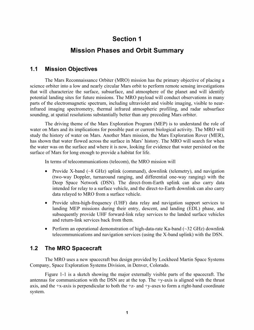
The Mars Reconnaissance Orbiter (MRO) mission has the primary objective of placing a
science orbiter into a low and nearly circular Mars orbit to perform remote sensing investigations
that will characterize the surface, subsurface, and atmosphere of the planet and will identify
potential landing sites for future missions. The MRO payload will conduct observations in many
parts of the electromagnetic spectrum, including ultraviolet and visible imaging, visible to near-
infrared imaging spectrometry, thermal infrared atmospheric profiling, and radar subsurface
sounding, at spatial resolutions substantially better than any preceding Mars orbiter.
The driving theme of the Mars Exploration Program (MEP) is to understand the role of
water on Mars and its implications for possible past or current biological activity. The MRO will
study the history of water on Mars. Another Mars mission, the Mars Exploration Rover (MER),
has shown that water flowed across the surface in Mars’ history. The MRO will search for when
the water was on the surface and where it is now, looking for evidence that water persisted on the
surface of Mars for long enough to provide a habitat for life.
In terms of telecommunications (telecom), the MRO mission will
• Provide X-band (~8 GHz) uplink (command), downlink (telemetry), and navigation
(two-way Doppler, turnaround ranging, and differential one-way ranging) with the
Deep Space Network (DSN). The direct-from-Earth uplink can also carry data
intended for relay to a surface vehicle, and the direct-to-Earth downlink can also carry
data relayed to MRO from a surface vehicle.
• Provide ultra-high-frequency (UHF) data relay and navigation support services to
landing MEP missions during their entry, descent, and landing (EDL) phase, and
subsequently provide UHF forward-link relay services to the landed surface vehicles
and return-link services back from them.
• Perform an operational demonstration of high-data-rate Ka-band (~32 GHz) downlink
telecommunications and navigation services (using the X-band uplink) with the DSN.
1.2 The MRO Spacecraft
The MRO uses a new spacecraft bus design provided by Lockheed Martin Space Systems
Company, Space Exploration Systems Division, in Denver, Colorado.
Figure 1-1 is a sketch showing the major externally visible parts of the spacecraft. The
antennas for communication with the DSN are at the top. The +y-axis is aligned with the thrust
axis, and the +x-axis is perpendicular to both the +z- and +y-axes to form a right-hand coordinate
system.

Mission Phases and Orbit Summary 2
High Gain Antenna
HiRISE
CTX
+y
+z+x
+y
+z+x
Low Gain Antennas (2)
HGA Gimbals
UHF Antenna
MCS
TWTA Panel
CRISM
Solar Array
Figure 1-1. Sketch of the MRO spacecraft with coordinate directions.
Of the two low-gain antennas (LGAs) that are fixed-mounted to the high-gain antenna
(HGA), LGA1 is called forward-facing because it is pointed in the same general direction as the
gimbaled HGA. The other LGA, LGA2, points generally in the opposite direction. Section 2
details the antennas and their pointing directions. The UHF antenna that is used for
communicating with surface vehicles is aligned with the +z-axis, vertical toward Mars. The
+z-axis is also the science instrument boresight. The direction of the Sun is generally toward the
–y-axis.
The orbiter payload consists of six science instruments and three new engineering
payload elements listed as follows:
• Science instruments
• HiRISE, High Resolution Imaging Science Experiment
• CRISM, Compact Reconnaissance Imaging Spectrometer for Mars
• MCS, Mars Climate Sounder
• MARCI, Mars Color Imager
• CTX, Context Camera
• SHARAD, Shallow (Subsurface) Radar
• New engineering payloads
• Electra UHF communications and navigation package
• ONC, Optical Navigation Camera Experiment
• Ka-band Telecommunications Experiment

Mission Phases and Orbit Summary 3
1.3 Mission Phases
In order of occurrence, the six phases of the MRO primary mission are: launch, cruise,
approach and orbit insertion, aerobraking, primary science, and relay.
The following paragraphs provide overviews of the spacecraft activities in each phase.
Specific telecom calibrations and activities are described in subsequent sections.
1.3.1 Launch
The spacecraft was launched on August 12, 2005. Approximately 58 minutes after
launch, the spacecraft separated from the launch vehicle. About 4 minutes prior to separation, the
X-band traveling-wave tube amplifier (TWTA) began warm-up, and the spacecraft began
transmitting a downlink through the forward-facing low-gain antenna (LGA1) about 1 minute
after separation. MRO remained in a single inertial attitude throughout the launch period. By 14
minutes after separation, the craft’s solar panels finished unfolding. About 21 minutes after
separation, in order to avoid interfering with solar array deployment, the HGA was deployed
from the stow position.
The spacecraft established radio contact with Earth 61 minutes after launch and within 4
minutes of separation from the upper stage. Initial downlink-only contact came through an
antenna at the Japan Aerospace Exploration Agency’s Uchinoura Space Center in southern
Japan.
When MRO came into view at the Goldstone, California, DSN site, a 34-m station
established an X-band uplink with the MRO receiver. The uplink carrier provided a reference for
two-way Doppler and turnaround ranging on the downlink, as well as establishing
commandability.
The ultra-stable oscillator (USO) in the telecom subsystem was turned on within hours
after launch so that the one-way downlink frequency would be stable prior to cruise phase
activities. The USO has been on continuously since, except for a few hours during safe mode in
January 2006.
1.3.2 Cruise
The cruise phase began about 3 days after launch and ended 60 days prior to Mars orbit
insertion (MOI). The duration of the cruise phase was approximately 150 days. The first
trajectory correction maneuver (TCM-1) included firing the six main (170-newton) thrusters for
15 seconds on August 27, 2005. This engine burn followed a 30-second burn of six smaller (22
newton) thrusters, which settled propellant in the craft’s fuel tank for smoother flow. With
communications on the LGA, MRO’s orientation was adjusted prior to the burns to point the
engines in the proper direction for the maneuver, and the spacecraft returned to cruise-phase
attitude after the trajectory adjustment. Besides putting MRO on course for the Mars target point,
TCM-1 checked out the engines required for MOI.
Instrument payload calibrations began on August 30. The higher-resolution cameras were
pointed at the Earth and the Moon as the spacecraft continued its flight to Mars.

Mission Phases and Orbit Summary 4
TCM-2, on November 18, 2005, used only the smaller TCM thrusters in a 20-second
burn. Two other TCMs built into the mission plan were not required.
1.3.3 Approach and Mars Orbit Insertion
Following the interplanetary cruise and Mars approach phases of the mission, the MRO
achieved MOI on March 10, 2006. The MOI burn fired the craft’s main thrusters for about 27
minutes to reduce velocity by about 20 percent as the spacecraft swung around Mars at about 5
km per second (11,000 miles per hour).
The initial post-MOI orbit started from the MOI aim point of 360 km above Mars’
surface, approaching from the south. After MOI and before the aerobraking phase began, the
orbiter flew about 426 kilometers (265 miles) above Mars’ surface at the nearest point (periapsis)
of each orbit, then swung out more than 43,000 kilometers (27,000 miles) to the most distant
point (apoapsis) before heading in again. The initial orbit period was about 35 hours.
After MOI, while preparing for aerobraking, the flight team tested several instruments,
obtaining the orbiter’s first Mars pictures and demonstrating the ability of its Mars Climate
Sounder instrument to track the atmosphere’s dust, water vapor, and temperatures.
1.3.4 Aerobraking
Aerobraking began on March 30, 2006 and ended August 30, 2006. The first aerobraking
maneuver fired the 22-newton thrusters for 58 seconds at apoapsis. That maneuver lowered the
subsequent periapsis altitude to 333 kilometers (207 miles). The aerobraking phase required 445
orbits of carefully calculated dips into Mars’ atmosphere. Aerobraking and a phasing maneuver
on September 5 shrank its orbit from the post-MOI elongated ellipse to a more nearly circular
orbit. Infrared-sensing instruments and cameras on two other Mars orbiters (Mars Odyssey and
Mars Global Surveyor) are expected to be the main sources of information to the advisory team
of atmospheric scientists, providing day-to-day data about variations in Mars’ atmosphere. In
addition, the Mars Climate Sounder instrument has the capability to monitor changes in
temperature that would affect the atmosphere’s thickness.
Aerobraking ended with MRO in a slightly elliptical low-altitude Sun-synchronous orbit,
called the science orbit. After a successful final circularization maneuver on September 11, the
science orbit has a period of 1 hour and 52 minutes, with an apoapsis of 316 km over the north
pole and a periapsis of 250 km over the south pole [1].
Solar Conjunction: Between the end of aerobraking (with the primary science orbit
established) and the start of the primary science mission phase is a solar conjunction. Defined as
the time period when the Sun–Earth–Mars angle is 5 deg or less, the conjunction is from
October 7 to November 8, 2006. The Ka-band communications demonstration was planned to
conduct activities during conjunction to monitor and compare simultaneous X- and Ka-band
telemetry downlinks. The DSN will support one 8-hr pass per day to a 34-m antenna during this
period.
Plans for solar conjunction telecom experiments are described in Section 5.
Solar conjunctions of Mars have a periodicity of about 26 months, and the Earth–Mars
range is very nearly maximum when the Sun–Earth–Mars angle is minimum at conjunction. The

Mission Phases and Orbit Summary 5
Sun–Earth–Mars geometry at conjunction causes communications between Earth and Mars to be
degraded. Proximity communications with surface vehicles would not be directly affected.
1.3.5 Primary Science Mission
During the science phase, MRO will examine parts of the planet in detail and monitor the
entire planet daily throughout a full cycle of Martian seasons. The duration of this phase is
approximately 740 days, which is slightly longer than one Martian year (687 Earth days). The
science experiments will consist of global mapping of Mars surface, regional surveys for
potential future Mars landing sites, targeted observations of areas of interest, and mapping of the
Mars gravity field. The primary science mission ends with the onset of the next solar
conjunction.1 Figure 1-2 shows the Mars-to-Earth range in the primary science phase.
At the beginning of the science phase, Mars will be about one-third of the way through a
northern hemisphere summer. Throughout the phase, the orbiter will generally keep its
instruments pointed at Mars to collect data and its high-gain antenna pointed at Earth to send the
data home. During this phase, conducting science observations will be more complex than in
previous Mars missions, because MRO must coordinate three basic observation goals:
Figure 1-2. Mars-to-Earth range during the primary science phase.
1 While the primary science phase is planned to end in 2008 after one Martian year, the National Aeronautics and
Space Administration (NASA) may approve the continuation of science observations beyond the primary science
phase until 2010, the end of the next major phase, the relay phase.

Mission Phases and Orbit Summary 6
• Daily global mapping and profiling
• Regional surveys
• Globally distributed targeting of hundreds of specific sites
Many targeted observations will also involve nearly simultaneous, coordinated
observations by more than one instrument.
During this phase, primary communications will be through the HGA to a 34-m DSN
station. Precise Doppler measurements will be taken to aid the gravity science experiments.
Several times a day, the orbiter will point to an off-nadir target for high-resolution imaging for
about 15 minutes. During these slews, the HGA pointing error will increase, but communications
with Earth will still be possible.
During primary science, the DSN allocation to MRO is two 34-m passes at X-band per
day, plus three 70-m passes per week. In addition, there will be two MRO 34-m Ka-band passes
per week.
1.3.6 Relay Mission
Beginning six months before the end of the primary science mission in December 2008
and continuing until the end of the MRO primary mission in December 2010, the Electra payload
will provide relay support to various Mars assets. During this relay phase, the Jet Propulsion
Laboratory (JPL) Mission Management Office (MMO) is chartered to coordinate relay services
between Martian surface assets and MRO. The coordination plan is based on a four-week
planning cycle for relay coordination, with weekly updates for ad hoc relay opportunity
assignment. The planned relay mission includes support of two spacecraft arriving at Mars and
descending to the surface:
Phoenix: The Phoenix mission is the first in NASA’s Mars Scout program, an initiative
for smaller, relatively lower-cost spacecraft to complement the major missions. The Phoenix
mission is in development for launch in August 2007 with landing in May 2008, about 75% of
the way through the MRO prime science phase. Phoenix is planned to land in icy soils inside the
Arctic Circle, near the north polar ice cap of Mars at the end of Martian spring. During the
Phoenix surface mission, the MRO mission plan states that Phoenix expects to request two to
three relay contacts daily with MRO’s Electra at rates of up to 128 kilobits per second (kbps).
Mars Science Laboratory: The Mars Science Laboratory (MSL), the next-generation
Mars rover, is slated for launch in October 2009 and landing on Mars in October 2010. For MSL,
MRO will receive one-way Doppler during EDL and two-way Doppler for post-EDL
reconstruction. After the MSL landing, MRO/Electra will be prime (with the Odyssey orbiter
backup) for the surface-orbiter proximity communications relay, providing navigation and timing
services, as well as forward- and return-link relay services.
For forward-link relay events, MRO has allocated space on the solid-state recorder (SSR)
to store and forward up to 30 Mbits/day. For return-link events, the allocation is 5 Gbits per day
for all landers. The MRO ground system has its own requirements for maximum data volume
and data latency for data relayed from each lander during the primary science phase.

Mission Phases and Orbit Summary 7
Figure 1-3 shows the activities performed during a typical relay session. Relay sessions
between MRO and a surface asset will be initiated by MRO. All information can be transferred
via a reliable link—the Proximity-1 protocol (Prox-1). In outline, at the time of the overflight,
MRO will hail the surface asset. Once the surface asset has responded, the session will begin.
Once all the data have been transferred or the overflight is about to end, MRO will terminate the
link. If no scheduled termination time is forced, the link drops out due to geometric constraints,
forcing a hard link termination. The link session is later closed out by MRO Electra via the time
out of a loss-of-lock event timer.
Return-link data will be downlinked at X-band from MRO to Earth at the earliest
opportunity. The return-link data will have the highest priority, and each frame will be sent
twice.2
End of MRO Primary Mission: The nominal end of the MRO primary mission, which
concludes with the relay phase, occurs at the end of 2010. The MRO orbit will then be raised to
350 km (periapsis) by 410 km (apoapsis) in order to extend the orbital lifetime. MRO has been
allocated enough Attitude Control Subsystem (ACS) propellant to nominally last through 2015.
During the extended mission period, MRO will likely continue relay operations.
1.3.7 Safe Mode
Safe mode provides a known, stable spacecraft configuration in case of a spacecraft
anomaly. Safe mode may be entered via command (for example, for a flight software reboot) or
from fault protection during any mission phase.
Figure 1-3. A typical sequence of activities during a relay session.
2 The relay-data completeness requirements levied on MRO have caused the project to respond by applying one
retransmission of all relay data to Earth. The X-band downlink is not protected by a protocol like Proximity-1.

Mission Phases and Orbit Summary 8
When MRO is configured in safe mode, LGA1 is boresighted at Earth, and the solar
arrays are Sun-pointed. The spacecraft –y-axis will track the Sun. Onboard Sun and Earth
ephemerides that were loaded before launch are used to determine the Sun–probe–Earth (SPE)
angle upon entry into safe mode and are used to point the HGA such that the forward-facing
LGA1 boresight is pointed generally at Earth. The star trackers can be used to help with Sun
acquisition if the spacecraft attitude knowledge is not good.
If the star trackers are not functioning and attitude knowledge is limited to that from Sun
sensors, the spacecraft will rotate about its –y-axis (which in safe mode is pointed at the Sun)
with a period of one hour for most mission phases. The rotation will cause the LGA1 boresight
relative to the Earth to trace a cone of approximately half the SPE angle. As a result, the DSN
station will observe a repeating power-level profile that depends on the SPE and LGA pattern.
In safe mode, the default USO is powered on. The X-band telecom transmit and receive
paths are via LGA1. In safe mode, the command bit rate is set to 7.8125 bits per second (bps),
and the X-band telemetry bit rate is set to 34.4 bps with (7,1/2) + Reed–Solomon (interleaving
depth, I = 1) encoding. The short frame length reduces frame acquisition time at the station.
Further actions in safe mode ensure the Ka-band TWTA is powered off, and the small
deep-space transponder (SDST) Ka-band exciter is turned off. The fault protection software also
safes the Electra UHF transceiver (EUT).
1.4 The MRO Orbit and Its Relay Coverage for Surface Vehicles
MRO and Odyssey are the two NASA orbiters with Proximity-1 relay communications
capability. Their orbits are Sun synchronous. Each time the orbiter crosses over Mars’ equator
from south to north, the mean local solar time (LST) at the ground directly below is 3:00 p.m.
(MRO) or 5:00 a.m. (Odyssey).
Table 1-1 shows the orbit elements and related data for MRO and Odyssey. The MRO
relay coverage defined in the three figures that follow is based on these values. Figures 1-4
through and 1-6 define geometric coverage conditions between MRO and a surface vehicle as a
function of the Martian latitude of the surface vehicle. The figures are based on composite
statistics averaged over longitude and reflecting the maximum, average, or minimum over a
24-sol simulation using the Telecom Orbit Analysis and Simulation Tool (TOAST) [8].
Figure 1-4 shows the number of contacts (lasting at least 1 minute above 10 deg).
Figure 1-5 shows potential average and maximum MRO pass durations in minutes as a function
of landed latitude, assuming a 10-deg minimum elevation angle from the surface. Pass duration
is the time the orbiter appears above the minimum elevation angle.3 Figure 1-6 shows the
maximum gap times between potential contacts with MRO. A gap is the duration of time
between geometric contact opportunities. In polar locations, for the 1-hour 52-min MRO orbit,
the gaps would be about 1-3/4 hours. At some near-equatorial latitudes, there is one contact per
sol, resulting in a gap longer than 24 hours.
3 The minimum 10-deg elevation angle and assumed minimum 1-minute pass duration are for illustration. The figure
omits minimum pass duration, which is generally not a useful statistic. For a near-circular Sun-synchronous orbit,
there will always be a pass geometry that results in near-zero pass time except for surface locations near the poles.

Mission Phases and Orbit Summary 9
Table 1-1. Orbit elements for MRO and Odyssey.
Orbit Element MRO Odyssey
Periapsis radius (km) 3624.4 3766.1
Apoapsis radius (km) 3691.1 3839.5
Semi-major axis (km) 3657.7 3802.8
Eccentricity 0.0091 0.0096
Inclination (deg) 92.6 93.1
Ascending node (deg) –14.7 –159.8
Perigee argument (deg) –78.8 –83.7
Time from perigee (s) –1818.8 –1423.8
Epoch 2008-147T01:00:00 2008-147T01:00:00
Related data MRO Odyssey
Periapsis altitude/location 255 km/south pole 370 km/south pole
Apoapsis altitude/location 320 km/north pole 444 km/north pole
Mean LST, ascending node 3:00 p.m. 5:00 a.m.
Mean LST, descending node 3:00 a.m. 5:00 p.m.
Orbit period 1 hr 52 min 1 hr 58 min
0
2
4
6
8
10
12
14
-90 -75 -60 -45 -30 -15 0 15 30 45 60 75 90
Mars latitude, degrees
MR
O n
um
be
r o
f c
on
tac
ts p
er
So
l
Figure 1-4. Maximum, average, and minimum number of contacts per sol
versus latitude of the lander for MRO orbit.

Mission Phases and Orbit Summary 10
0
1
2
3
4
5
6
7
8
9
10
-90 -75 -60 -45 -30 -15 0 15 30 45 60 75 90
Mars latitude, degrees
MR
O p
ass d
ura
tio
n,
min
ute
s
Figure 1-5. Maximum (top) and average (bottom) pass duration versus
Mars latitude for MRO orbit.
0
4
8
12
16
20
24
-90 -75 -60 -45 -30 -15 0 15 30 45 60 75 90
Mars latitude, deg
MR
O m
axim
um
gap
, h
ou
rs
Figure 1-6. Maximum gap between potential MRO contacts versus Mars latitude.

Mission Phases and Orbit Summary 11
1.5 MRO Orbit Phasing to Support Landing Vehicle EDL
To cover a critical event such as an arriving spacecraft’s EDL, MRO can perform an orbit
trim maneuver to adjust the orbit phasing (that is, adjust the true anomaly of the orbit). However,
MRO doesn’t have the propellant budget necessary to make an orbit plane change (that is,
significantly shift the local time of the orbit plane). Orbit phasing moves the timing of the orbiter
forward or backward in its orbit so that when a spacecraft arrives at Mars the relay orbiter will be
in a good orbit position to provide telecom and navigation support for critical events surrounding
arrival. Communications during EDL would normally be one-way (return link to MRO only).
The antenna placement on an arriving/descending vehicle and that vehicle’s attitudes
relative to the orbiter are critical to maintaining communication during EDL. It may be possible
to coordinate roll steering of up to ±30 deg to point MRO’s antenna to improve EDL coverage.
Plasma outages on the lander–MRO return link during atmospheric entry may occur
depending on the entering spacecraft’s approach angle and velocity.

12
Section 2
Telecommunications Subsystem Overview
2.1 X-Band: Cruise and Orbital Operations
Uplinks to MRO and downlinks from MRO at X-band are the primary means of
communication between the MRO and the DSN antennas in California, Spain, and Australia.
The X-band communication system on the orbiter uses a 3-meter-diameter (10-foot)
high-gain antenna and a 100-watt X-band traveling-wave tube amplifier to transmit signals to
Earth. Each of these devices is more than twice as capable as those used by previous Mars
missions. As a result, MRO will be able to send data back to Earth more than 10 times faster than
previous missions.
At a maximum distance from Earth (400 million km [250 million miles]), the orbiter is
designed to send data at a rate of at least 500 kbps. At closer ranges, the signal strength will be
greater, so higher data rates will be possible. When the orbiter is at its closest ranges (about 100
milliom km [60 million miles]), for several months the orbiter will be able to send data to Earth
at 3 to 4 megabits per second (Mbps).
The MRO project will schedule two 34-m Deep Space Stations (DSSs) daily for an
average of 16 hours per day during the science phase. Twice a week, the 70-m antennas also will
be requested.
With its large antenna, high-powered TWTA, and fast computer, the orbiter can transmit
data to Earth at rates as high as 6 Mbps. This rate is quite high considering that MRO will
achieve it while 100 million kilometers from Earth. Over its 2-year primary science mission, the
spacecraft is predicted to transmit more than 34 terabits. That’s equivalent to 4 terabytes of
data—about as much as can be stored on 6,500 compact disks. It’s also 10 to 20 times more data
than previous Mars missions and more data than all previous planetary missions combined.
From the viewpoint of a Deep Space Network antenna on Earth, the orbiter spends about
one-third of its time in every orbit behind Mars. During these times, the orbiter is occulted (has
no line-of-sight communications path with the Earth) and cannot communicate with the DSN.
Out of 16 hours daily that Deep Space Network tracking could potentially be scheduled, MRO is
actually planned to send data to Earth for 10 to 11 hours for about 700 days. The data rate will
average between 0.5 and 4 Mbps.
Figure 2-1 is a block diagram of the MRO telecom subsystem. Of the redundant active
elements (EUTs, USOs, SDSTs, and X-band TWTAs), only one is powered on at a time.
The subsystem mass and spacecraft power input are summarized in Table 2-1.
The mass values are the totals for both redundant units for the SDSTs, X-band TWTAs,
and UHF transceivers. The mass of microwave components, cabling, and waveguides (WGs) not
individually called out is summed for the major telecom functional elements.

Telecommunications Subsystem Overview 13
LG
A1
Tx/
Rx
(-25
deg
)
LG
A2
Tx/
Rx
(115
deg
)
C&
DH
A&
B
CP
1
XT
WT
A1
XT
WT
A2
BP
F3
RXAnt
TX
IS1
IS2
DX
2S
5
TW
TA
En
clo
sure
(H
GA
Mo
un
ted
)
IS3
HG
A (
3.0m
)
Z1
0°90°
INISO
x4Ka
TW
TA
US
O2
US
O1
SD
ST
1C
DU
A/B
Ka
Ou
t15
53A
/BX
Ou
tX
TL
MA
/BK
aT
LM
Rx
In
EU
T2
C&
CR
S-4
22A
/BH
SD
LV
DS
A/B
Wu
p/T
ick
A/B
Te
mp
EU
T1
C&
CR
S-4
22A
/BH
SD
LV
DS
A/B
Wu
p/T
ick
A/B
Te
mp
SD
ST
2C
DU
A/B
Ka
Ou
t15
53A
/BX
Ou
tX
TL
MA
/BK
aT
LM
Rx
In
UH
F T
x/R
x(N
adir
)
0°90°
INISO
Z2
CP
2
S2
S1
RXAnt
TX
DX
1
S4
BP
F1
BP
F2
S3
Fig
ure
2-1
. M
RO
Tel
ecom
Su
bsy
stem
blo
ck d
iagra
m.

Telecommunications Subsystem Overview 14
The project book keeps the HGA gimbals and their drive motors in a different subsystem.
However, they are included in Table 2-1 as they would not be on the spacecraft except to direct
the HGA to Earth.
Table 2-1. MRO telecom mass and power summary.
Assembly Subtotal,
kg Total
mass, kg
Spacecraft
power input,
W RF power
output, W Note
X-band transponder 6.4 16
Orbit average
power
SDSTs (2) 5.8
x4 frequency multiplier+bracket 0.1
Other microwave components 0.5
Traveling-wave tube amplifiers 12.1
X-band TWTAs (2) 1.9 172 102 100 W nominal
Ka-band TWTA 0.8 81 34 35 W nominal
X-band electronic power converters 3.0
Ka-band electronic power converter 1.5
Diplexers and brackets 1.8
Waveguide transfer switches 1.5
Other microwave components 1.4
Miscellaneous TWTA hardware 0.2
X-band and Ka-band antennas 22.6
HGA prime reflector 19.1
Antenna feed assembly 1.6
LGAs and polarizers 0.8
Miscellaneous antenna hardware 1.1
HGA gimbals and drive motors 45.0 14
Orbit average
power
Waveguides and coax 8.3
USOs (2) 1.7 5
Orbit average
power
UHF subsystem 11.5
Electra transceivers (2) (each
transciever has an integral solid-state
RF power amplifier) 10.1 71 5
On, full duplex
(17.4 W standby)
UHF antenna and radome 1.4
String switch (S) 0.1
Telecom total 107.7 359

Telecommunications Subsystem Overview 15
The X-band system was designed to have no single point of failure (with the exception of
the HGA, couplers, and diplexers), and to minimize circuit loss. The coupler (CP) and diplexer
(DX) are waived because the probability of failure of these components is very low. Both are
passive radio frequency (RF) components with no moving parts and no electronics.
X-Band Microwave Elements: In Figure 2-1, S1, S2, and S3 are waveguide transfer
switches. S1 allows for the output of either TWTA to be sent either to the HGA or to either
LGA. S2 and S3 allow for the selection between LGA1 and LGA2. S4 is a coaxial (coax)
transfer switch that routes the uplink to either SDST1 or SDST2.
The RF switches are designed such that the switches will fail in either of two switch
positions. The probability that the switch will fail in between positions is remote.
The bandpass filters (BPFs) BPF1 and BPF2 are coaxial bandpass filters centered at the
X-band receive frequency (7.183 GHz). They are used to filter out interference from the X-band
TWTA output that could leak from the transmit port of the diplexer to the receiver port.
BPF3 is a waveguide bandpass filter that is centered at the transmit frequency (8.439
GHz) and is used to filter out the harmonics of the transmit frequency. This is needed to prevent
interference to ground receivers operating in frequency bands that are the second, third, or fourth
harmonics of the X-band output (that is, 16.9 GHz, 25.3 GHz, and 33.8 GHz), in particular
during the first few days after launch when the power flux density of the downlink signal is high.
BPF3 has no effect on transmissions through the HGA.
The isolators (ISs) IS1 and IS2 are X-band isolators to protect the X-band TWTA in case
of a temporary short in the transmit path to the antenna. IS3 is the Ka-band isolator. The couplers
in between the SDSTs and the TWTAs allow either SDST to drive either TWTA.
The USOs are cross-strapped (cross-strapping not shown) so that, if one fails, the other
can be used by either SDST.
Ka-Band Elements: The Ka-band telemetry streams are cross-strapped. SDST1 gets its
input data for Ka-band from command and data handling side A (C&DH-A) only, and SDST2
gets its input for Ka-band from command and data handling side B (C&DH-B) only. The Ka
band transmit chain is part of an operational demonstration experiment and therefore does not
have to be single-fault tolerant.
2.1.1 High-Gain Antenna
The HGA consists of three main components—the feed, an ellipsoidal subreflector, and a
3-m offset parabolic main reflector. The HGA subreflector is 0.45 m in diameter and is located
near the focal point of the main reflector. The X-band feed is a corrugated horn design, while the
Ka-band feed is a disc-on-rod design. There is no uplink reception at Ka-band, only downlink
transmission. The feeds contain polarizers at X-band and at Ka-band to generate right circularly
polarized (RCP) microwaves.
Figure 2-2 shows the HGA pointing loss (the antenna gain relative to a reference 0-dB
value at boresight) at X-band transmit and receive frequencies.
Figure 2-3 shows the HGA pointing loss at the Ka-band transmit frequency.

Telecommunications Subsystem Overview 16
-14
-13
-12
-11
-10
-9
-8
-7
-6
-5
-4
-3
-2
-1
0
0 1 2 3 4 5 6 7 8 9 10 11 12
Offpoint Angle, mrad
Po
inti
ng
Lo
ss
, d
BX-band Transmit
X-band Receive
Figure 2-2. HGA X-band transmit and receive pointing loss relative to boresight.
-30
-28
-26
-24
-22
-20
-18
-16
-14
-12
-10
-8
-6
-4
-2
0
0 1 2 3 4 5 6 7 8 9 10 11
Offpoint Angle, mrad
Po
inti
ng
Lo
ss
, d
B
Phi = 0 deg
Phi = 90 deg
Figure 2-3. HGA Ka-band transmit pointing loss relative to boresight.

Telecommunications Subsystem Overview 17
The pre-launch HGA patterns are representative and are planned to be updated by in-
flight calibrations.
The high-gain antenna, deployed shortly after launch, has since served as the primary
means of communication to and from the orbiter.
The high-gain antenna must be pointed accurately and therefore is steered using the
gimbal mechanism. The requirement for HGA pointing accuracy is 2.08 mrad at 99.7% circular
error probability (CEP). This is a requirement on the mechanical system, in particular the gimbal
motor, that affects the link performance.
There are three gimbal mechanisms onboard Mars Reconnaissance Orbiter:
• One that allows the high-gain antenna to move in order to point at Earth
• Two that allow the solar arrays to move to point at the Sun
Each of the gimbals can move about two axes. As the spacecraft travels around Mars
each orbit, these gimbals allow both solar arrays always to be pointed toward the Sun, while the
high-gain antenna can simultaneously always be pointed at Earth.
2.1.2 Low-Gain Antenna
Two low-gain antennas are present for lower-rate communication during emergencies
and special events, such as launch, MOI, or safe mode. The data-rate capability when using these
antennas is lower because they focus the radio beam much more broadly than does the high-gain
antenna. Figure 2-4 shows the pointing loss of the LGA at X-band transmit and receive
frequencies. The LGA does not provide Ka-band capability.
-20
-18
-16
-14
-12
-10
-8
-6
-4
-2
0
0 10 20 30 40 50 60 70 80 90
Off boresight angle, deg
Po
inti
ng
Lo
ss
, d
B
LGA Tx 8439 MHz
LGA RX 7183 MHz
Figure 2-4. LGA X-band transmit and receive pointing loss relative to boresight.

Telecommunications Subsystem Overview 18
The LGA is a horn design. It is essentially an open waveguide with RF choke rings at the
end for pattern uniformity and side-lobe control. A septum polarizer placed before the waveguide
horn provides RCP.
The two low-gain antennas are mounted on the high-gain antenna dish—one on the front
side and one on the back—and are moved with it. In that placement, the two LGAs make
communication with the DSN possible at all times, no matter what the position of the spacecraft
might be at a given time.
The forward-facing LGA1 is mounted near the rim of the HGA and is canted 25 deg from
the HGA boresight. The cant angle was selected based on the off-point angle at critical
spacecraft events, such as during TCMs and MOI, when the HGA is locked in position and not
tracking Earth. The aft-facing LGA2 is mounted on the TWTA panel and is canted at –115 deg
from the HGA boresight.
Table 2-2 summarizes key HGA and LGA link parameters as determined before launch.
Table 2-2. LGA and HGA antenna link parameters.
Parameter
LGA
X-band
transmit
LGA
X-band
receive
HGA
X-band
transmit
HGA
X-band
receive
HGA
Ka-band
transmit
Boresight gain 8.8 dBi 8.4 dBi 46.7 dBi 45.2 dBi 56.4 dBi
Gain tolerance ±0.5 dB ±0.5 dB ±0.5 dB ±0.5 dB ±1.0 dB
Axial ratio (max) 2 dB 2 dB 1.1 dB 2.2 dB 2.3 dB
Polarization RCP RCP RCP RCP RCP
Antenna return
loss (max) –18 dB –18 dB –19 dB –23 dB –19 dB
Half-power
beamwidth 0.69 deg 0.18 deg
Pointing error
budget (3-sigma) 2.08 mr 2.08 mr 2.08 mr
2.1.3 Transponders
MRO carries two small deep-space transponders (SDSTs). The SDSTs provide identical
functions, and only one is powered on at a time. The SDST is a proven transponder with heritage
from previous missions described in earlier articles from this DESCANSO series: Deep Space 1,
Mars Odyssey, and MER. The SDST is responsible for tracking the uplink carrier, demodulating
commands from the carrier, generating the downlink carrier (coherent or non-coherent with the
uplink frequency), performing convolutional coding, producing different subcarrier frequencies,
modulating telemetry on the subcarrier or directly on the downlink carrier, demodulating and
modulating turnaround ranging signals, and generating differential one-way ranging (DOR)
tones.

Telecommunications Subsystem Overview 19
The SDST is composed of four different modules: the digital processing module (DPM),
the downconverter module, the power module, and the exciter module. The MRO SDST has
several features differing from previous SDST designs:
• The MRO x4 (times-four) multiplier that is used to generate the 32.2-GHz Ka-band
signal from the 840f1 frequency output4 (8052 MHz) is external to the SDST and
placed on the TWTA panel (whereas the SDST is located middeck); this is done to
minimize coaxial cable loss at Ka-band. In Deep Space 1 (DS1), the x4 multiplier was
internal to the SDST.
• The line receivers in the DPM are now low-voltage differential signaling (LVDS)
receivers to support high-rate transmission over the compact peripheral component
interconnect (cPCI) bus.
• A field programmable gate array (FPGA) with 72 thousand gates has been added to
the MRO SDST to support quadrature phase-shift keying (QPSK). The FPGA also
performs (7,1/2) convolutional coding5 for QPSK.
• Wideband DOR (8f1 DOR) capability has been added at Ka-band.
The SDST has an internal, five-pole, 5.8-MHz low-pass filter (LPF) that filters input
voltage to the phase modulator. Nominally, the MRO SDST will be configured to operate in the
filtered mode. The filter reduces the amplitude of high-frequency components in the telemetry
downlink to avoid interference to other missions. Use of the unfiltered mode is permitted only
when the telemetry spectrum would not interfere with another mission.
Table 2-3 lists some of the parameter values that determine link configuration and
performance for the MRO SDST.
2.1.4 RF Amplifiers
Located on the back side of the high-gain antenna is the enclosure for the TWTAs and
associated microwave components. The enclosure is called the TWTA panel in the Figure 1-1
sketch of external MRO components.
Figure 2-5 shows the layout of the bottom side of the TWTA panel, showing two of the
TWTAs, the three power converters, and most microwave elements (diplexers, X-band bandpass
filter, and isolator). The Ka-band TWTA and isolator are on the top side of the TWTA panel and
are not visible in Figure 2-5.
4 In SDST nomenclature, f1 is the fundamental frequency from which the uplink and downlink frequencies are
derived. For example, the X-band downlink is 880f1, and the X-band uplink is 749f1. The Ka-band downlink
carrier is 3360f1, which is 4x the SDST’s Ka-band output at 840f1. The MRO SDST operates on DSN channel 32.
For this channel, f1 is approximately 9.59 MHz.
5 Note that telemetry can be convolutionally coded in the SDST as on previous missions, but only with the (7,1/2)
rate planned for use on MRO. For a turbo-coded telemetry downlink, the input to the SDST has been turbo coded in
the C&DH upstream of the SDST. In this case, the stream of turbo symbols at the SDST telemetry input are treated
by the SDST as bits, with the SDST’s convolutional coder bypassed.

Telecommunications Subsystem Overview 20
Table 2-3. SDST link configuration and performance parameters.
Parameter Value
Receiver input levels, dBm –156 dBm (threshold) to -70 dBm
Receiver 2-sided carrier loop
bandwidth, Hz
20 (threshold)
Command data rates (bps, uncoded) 7.8125, 15.625, 31.25, 62.5, 125, 250, 500,
1000, 2000 bps
Command subcarrier modulation index 0.5 to 1.5 radians, peak
Minimum telemetry symbol rate 0 bps on subcarrier, 2000 sps on carrier
Maximum symbol rate Specified to 4.4 megasymbols per second
(Msps) in normal (filtered) mode, tested to 6
Msps
Telemetry modulation index range 64 equal steps of modulation voltage from 0 to
135 deg
Turnaround ranging modulation index 4.375, 8.75, 17.5, 35, 70 deg.peak (accuracy
±10%, stability ±20%)
DOR modulation index, peak 28 deg peak (accuracy ±10%, stability ±25%)
Ka-band output modulation bandwidth Normal mode 5.5 ± 1.5 MHz, wideband mode
10 MHz minimum
HVPS X1
HVPS X2
TWTA X1
TWTA X2
ISOLATOR
DIPLEXER 1
DIPLEXER 2
HVPS Ka
WG BPF
HVPS X1
HVPS X2
TWTA X1
TWTA X2
ISOLATOR
DIPLEXER 1
DIPLEXER 2
HVPS Ka
WG BPF
Figure 2-5. Layout of microwave components in the TWTA panel.

Telecommunications Subsystem Overview 21
There are three amplifiers on board, two at X-band (only one powered at a time) and one
at Ka-band. The nominal TWTA RF output power is 100 W at X-band (102 W measured pre-
launch) and 35 W at Ka-band (34 W measured).
Each TWTA consists of two main components, the high-voltage power supply (HVPS),
also called the electronic power converter (EPC), and the traveling-wave tube (TWT).
The diplexer is a passive device that allows for routing of X-band transmit and receive
frequency signals that are present simultaneously at the antenna. The diplexer has three ports: the
antenna port, the receive port, and the transmit port. The isolation between transmit and receive
ports is essential to avoid self-interference within the subsystem. The diplexer also provides
significant attenuation of transmit frequency harmonics.
The passband at the receive port is centered at 7.183 GHz to allow for the uplink signal
from the antenna port to pass through to the receive port. The passband at the transmit port is
centered at 8.439 GHz to allow the output of the X-band TWTA to pass to the antenna port.
Additional attenuation of transmit frequency harmonics occurs in the waveguide
bandpass filter in the LGA transmit path. Each isolator (one is called out in Figure 2-5) protects
its TWTA against RF power reflected back by a momentary short at the output.
Each TWTA provides three kinds of protection for itself and the spacecraft power supply:
• Helix Overcurrent Trip. If helix current exceeds 5 mA, the power converter,
responding within 2 ms, goes into an automatic restart mode involving removal and
reapplication of the high voltage to the TWT.
• Power Converter Overcurrent Trip. If the input current exceeds a maximum value,
the switching transistor is protected by cycle peak current limitation. Also, after about
2 ms, the converter goes into the automatic restart mode.
• Bus Undervoltage Trip. If the bus voltage at the converter input drops below 20.5 V,
the high voltage switches off, and an undervoltage trip status flag is set. When the bus
voltage rises above 21.5 V again, the TWTA startup sequence is initiated and
preheating begins. The preheating lasts about 210 seconds. The nominal bus voltage
is 28 V.
2.2 UHF: Proximity Relay Communications
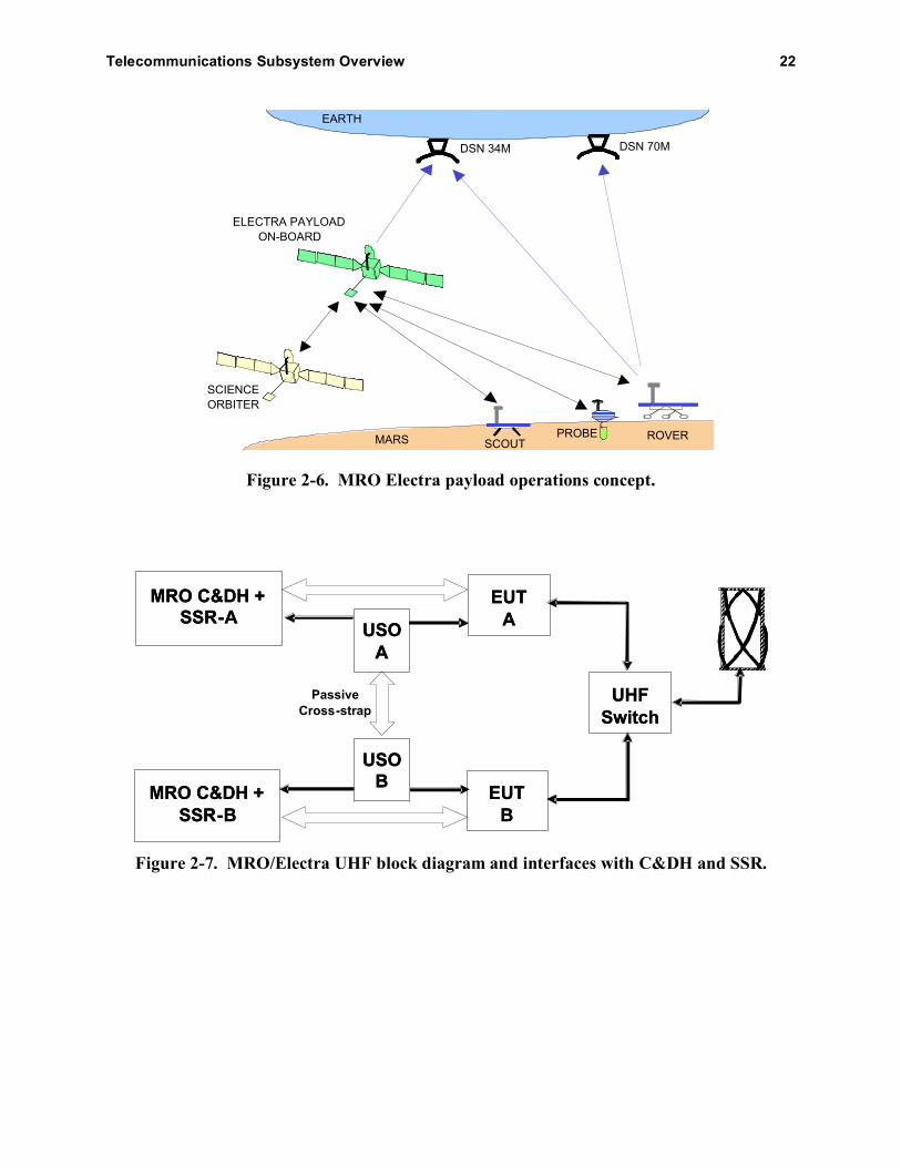
As shown in Figure 2-6, the Electra payload in MRO becomes a network node in the
Mars network constellation that provides efficient relay of high-rate in-situ mission science and
engineering data. The first landing vehicles that are planned to use MRO/Electra operationally
are Phoenix and MSL.
Figure 2-7 is a block diagram of the MRO UHF system and its interfaces (I/Fs) with the
command and data handling (C&DH) and SSR systems. The EUTs and the USOs (which also
support the X-band and Ka-band systems) are redundant. The diagram shows the allowable
combinations of redundant USOs and EUTs with the C&DH sides and the redundant SSRs.
Figure 2-8 is a sketch of the EUT.
Telecommunications Subsystem Overview 22
MARS
EARTH
DSN 34M DSN 70M
PROBE
SCIENCE
ORBITER
SCOUTROVER
ELECTRA PAYLOAD
ON-BOARD
Figure 2-6. MRO Electra payload operations concept.
USO
A
USO
A
USO
B
USO
B
Passive
Cross-strap
EUT
A
EUT
A
EUT
B
EUT
B
UHF
Switch
UHF
Switch
MRO C&DH +
SSR-A
MRO C&DH +
SSR-A
MRO C&DH +
SSR-B
MRO C&DH +
SSR-B
Figure 2-7. MRO/Electra UHF block diagram and interfaces with C&DH and SSR.

Telecommunications Subsystem Overview 23
Figure 2-8. Electra UHF transceiver (EUT) assembly.
The EUT assembly consists of five modular slices. From top to bottom, the slices are
• Half-duplex overlay (HDO) receiver filter and UHF diplexer
• Filtering and switch unit (FSU)
• UHF radio frequency module (RFM, the receiver and transmitter)
• Baseband processor module (BPM)
• Power supply module (PSM) with integral power amplifier module
The FSU slice in the MRO EUT consists of a high-isolation diplexer, the HDO
receive/transmit (R/T) switch, and the coaxial transfer switch. The BPM slice interfaces directly
with MRO C&DH, the MRO SSR, the USO, and the modules that comprise the EUT.
The RFM slice consists of a single-channel UHF transmitter and receiver.
The PSM slice consists of the power supply and the driver/power amplifier. The PSM
provides power to the BPM and, under BPM control, to the elements of the RFM. The PSM slice
also includes a power amplifier that amplifies the modulated signal to the appropriate RF output
level.
The BPM performs all signal processing, provides overall EUT control, and services the
external spacecraft interfaces.
The functionality of the modem processor (MP) portion of the BPM is summarized in
block diagram form in Figure 2-9 [9].
The BPM consists of a 32-bit microprocessor, two radiation-hardened program-once field
programmable gate arrays (FPGAs), and a large (~1Mgate) reprogrammable FPGA, along with a
substantial amount of dynamic and static memory. The reprogrammable FPGA contains the

Telecommunications Subsystem Overview 24
Figure 2-9. Electra transceiver block diagram.
modem functions and is reprogrammable post-launch. The 32-bit microprocessor manages the
EUT and the relay Prox-1 protocol.6
In concept, one side of the BPM handles the spacecraft interfaces. A dedicated 1553
transceiver chip supports the command and telemetry interface to the host C&DH. An LVDS
interface supports high-rate relay and radiometric data transfers through the high-speed data
(HSD) FPGA. The other side of the BPM handles the EUT, with the housekeeper (HK) FPGA
managing control and telemetry signals to and from the EUT front end, and the MP FPGA.
The main functions of the MP FPGA include
• Coding and decoding
• Modulation and demodulation
• Carrier, symbol, and decoder synchronization
• Prox-1 frame synchronization detection
• Prox-1 transmit (Tx) and receive (Rx) user data and control data buffering
• Receive signal level management, automatic gain control (AGC)
• Radiometric Doppler and open-loop record functions
6 The EUT complies with the Proximity-1 protocol defined by the Consultative Committee for Space Data Standards
(CCSDS) in [5]. In this article, the protocol is abbreviated Prox-1.

Telecommunications Subsystem Overview 25
• Clock (CLK) and timestamp functions
• Implementation of the physical layer of the communication link from baseband to an
intermediate frequency (IF)
The MRO Electra does not have an internal clock. The clocks for the BPM FPGAs,
including bit, symbol, and sample rate clocks, are derived from the external USO.
Table 2-4 defines the major operating modes, functions, and constraints for the MRO
EUT.
MRO Electra implements frequency agility and swappable transmit and receive bands.
The EUT complies with the CCSDS Prox-1 channel definitions for eight frequency pairs. In all,
Electra supports 16 preset frequency pairs, as defined in Table 2-5.
Table 2-4. MRO/Electra modes, functions, and performance.
Capability Values
Protocol Prox-1 (reliable and expedited link layer protocols)
Frequencies See next section (including Table 2-5)
Modes of operation Half-duplex7 Rx and Tx (no Prox-1 protocol in half
duplex)
Full-duplex transceiver
Full-duplex carrier modes Coherent, noncoherent
Transceiver RF output power 5.0 W full duplex, 7.0 W half duplex
Circuit loss, EUT to antenna –0.42 dB
Receiver thresholds, at antenna –130.8 dBm (1 kbps) to –99.6 dBm (1024 kbps) coded
–126.0 dBm (1 kbps) to –91.1 dBm (2048 kbps) uncoded
Carrier modulation modes Suppressed carrier, residual carrier (60 deg mod index)
Modulation types Residual carrier binary phase-shift keying (BPSK) with
bi-phase-L (Manchester). Suppressed-carrier BPSK
Frequency reference Ultra stable oscillator
Rx and Tx symbol rates 1, 2, 4, 8, 16, 32, 64, 128, 256, 512, 1024, 2048 ksps.
Also, adaptive data rate mode
Received signal power range –140 to –70 dBm
Encoding Uncoded, (k = 7, r = 1/2) convolutional, differential
symbol coding
Decoding Uncoded, (k = 7, r = 1/2) convolutional (3-bit soft
decode)
Scrambling/descrambling V.38
Acquisition and tracking loop Second-order PLL, with loop bandwidth 10 Hz to 10 kHz
(for received signal from –140 dBm to –70 dBm)
Tracking range and rate ±20 kHz, ±200 Hz/s
7 The term “full duplex” is used by MRO in the conventional sense of simultaneous forward and return link
capability at separate frequencies. The term “half duplex” means that Electra’s transmitter and receiver are not on
simultaneously even though the forward and return links may be on separate frequencies.

Telecommunications Subsystem Overview 26
Table 2-5. CCSDS Prox-1 “Blue Book” channel numbers and “preset” Electra frequencies.
Channel
Number
CCSDS
Forward
Frequency
(MHz)
MRO Preset
Forward
Frequency
(MHz)
CCSDS
Return
Frequency
(MHz)
MRO Preset
Return
Frequency
(MHz)
0 437.1 437.1 401.585625 401.585625
1 435.6 435.6 404.4 404.4
2 439.2 439.2 397.5 397.5
3 444.6 444.6 393.9 393.9
4 435 to 450 436 390 to 405 401.4
5 435 to 450 438 390 to 405 402
6 435 to 450 440 390 to 405 402.6
7 435 to 450 441 390 to 405 403.2
8 442 391
9 442.5 392
10 443 393
11 445 395
12 446 395.5
13 447 396
14 448 399
15 449 400
In addition to the 16 preset pairs, the MRO Electra radio has the capability to tune its Tx
and Rx frequencies across the entire 390-MHz-to-450-MHz band; thus, any frequency pair
combination within this band is possible. For half-duplex operation, any pair of frequencies will
work as an operational pair. For full-duplex operation, the Tx frequency must be chosen in the
range of 435 MHz to 450 MHz, and the Rx frequency must be chosen in the range of 390 to 405
MHz.
The MRO Electra payload provides a single nadir-looking (vertical down to Mars) UHF
LGA. The antenna shares the nadir deck with science payloads. Some parts of these nearby
payloads that are responsive at UHF frequencies couple with the antenna and distort its nominal
gain pattern. To compensate for this, the MRO mission plan allows for spacecraft roll steering of
up to 30 deg to point the better parts of the UHF antenna pattern toward the surface user. The
orbiter sets up for this pass by roll steering to a fixed roll angle. The Electra payload performs
the pass, and then the orbiter rolls back to the standard nadir pointing position.
Figures 2-10 (437.1 MHz) and 2-11 (401.6 MHz) show antenna gain in dBi versus angle
from boresight (cone or theta). In each figure, the solid curve is the average gain over cuts made
in the orthogonal axis (clock or phi). The dotted curves above and below the solid curve are the
gains for the best-case and worst-case clock cut, respectively. The antenna is RCP for both the
forward and return links.

Telecommunications Subsystem Overview 27
-3
-2
-1
0
1
2
3
4
5
6
0 15 30 45 60 75
Off boresight angle (theta), degrees
MR
O 4
37
.1 M
Hz (
rcp
) g
ain
, d
BI
Figure 2-10. MRO 437.1-MHz gain pattern.
-5
-4
-3
-2
-1
0
1
2
3
4
0 15 30 45 60 75
Off boresight angle (theta), degrees
MR
O 4
01.6
MH
z (
rcp
) g
ain
, d
Bi
Figure 2-11. MRO 401.6-MHz gain pattern.
The MRO Electra transceiver is compatible with the CCSDS Proximity-1 Space Link
Protocol [5,6].
Prox-1 transfer frames are sent on both the forward link (from the orbiter to the surface
vehicle) and the return link (surface back to the orbiter) using the Prox-1 protocol link
management in either reliable (retransmission) or expedited (no retransmission) mode. In
retransmission mode, an automatic repeat queueing (ARQ) protocol is utilized to request
retransmission of any proximity frames that are not received error-free. MRO also provides a
relay service (called “raw data”) not utilizing the Prox-1 protocol. The orbiter also provides a
form of Doppler data and a form of open-loop data. These data types or services are defined in
the following.

Telecommunications Subsystem Overview 28
2.2.1 Proximity-1 Data
Typically the MRO Electra will initiate a Prox-1 session by sending a string of “hail”
data packets while looking for a response from the specific lander identified in the hail packet.
This standard operating procedure can be reversed—that is, lander-initiated relay sessions are
possible. The hail includes information describing the session operating mode for both the
forward and return link directions. This includes, among other things, operating frequency, data
rate, and channel-coding mode.
2.2.2 Time Stamp Packets
Time stamp data consist of snapshots of the local Electra clock corresponding to the
ingress or egress times of Prox-1 frame-synchronization markers. Thus, time stamp data are only
collected in conjunction with Prox-1 mode operations. The time stamps are paired with
corresponding Prox-1 frame sequence numbers and noted as arriving or departing frames.
2.2.3 Raw Data
In raw data mode, there is no hailing or link establishment protocol, nor is there any
session data management or accounting protocol. A link is established by time sequence
transmissions and reception at both ends of the link. In addition to coordinated sequence timing,
both sides of the link must agree beforehand to the same data link mode settings—for example,
frequencies, data rates, and coding.
2.2.4 Phase and Power Data
MRO’s Electra transceiver can sample and record phase signal power of a phase-locked
received carrier signal. This radiometric information is highly accurate (being based on the MRO
USO signal and with successive samples tied directly to the USO-based local clock). Each
sample contains phase, AGC power, in-phase (I) amplitude, quadrature (Q) amplitude, and a
USO-based time. These data form the basis for a Doppler metric.
2.2.5 Open-Loop Data
Open-loop data consist of high-rate I and Q samples of the digital representation of the
downconverted signal given a fixed receive center frequency and no closed-loop signal tracking.
Data collection rate, data collection filter bandwidth, and data collection center frequency are
specified to achieve the capture of the intended surface user’s received signal bandwidth.
2.3 Ka-Band: Operational Demonstration
The MRO spacecraft has a fully functioning Ka-band downlink equipment suite,
comparable to that for the X-band downlink, including
• A one-way carrier (USO or auxiliary oscillator driven) or a two-way coherent carrier
(using the X-band uplink carrier frequency reference)

Telecommunications Subsystem Overview 29
• Modulation of telemetry with any of the available data rates, encoding types, and
modulation index values
• Modulation of turnaround ranging from the X-band uplink, with a settable modulation
index
• Modulation of differential one-way ranging tones, more widely spaced than at X
band; Ka-band tones are 76 MHz from the carrier, as compared with X-band tones at
19 MHz
The Ka-band components of the subsystem include a x4 (times-four) multiplier, a Ka
band TWTA and its power converter, a Ka-band feed element in the HGA, and other microwave
parts as defined in Section 2.1.
Deep Space Network 34-m antennas capable of receiving Ka-band will be requested
twice per week during the prime science mission as part of the demonstration.
30
Section 3
Ground Data System
3.1 Deep Space Network
The three primary DSN ground complexes are located near Goldstone (California),
Madrid (Spain), and Canberra (Australia). The DSN antennas are categorized according to their
diameter and performance. During cruise and orbit operations, MRO was allocated use of the
70-m antenna subnet, the 34-m beam-waveguide (BWG) antenna subnet, and the 34-m high-
efficiency (HEF) antenna subnet.
MRO used the 70-m antennas to support MOI and may require them for emergency mode
communications (safe mode operations on the LGA).
MRO depends on the 34-m BWG antennas for the vast majority of the mission telemetry
and commanding. The BWG antennas differ from the HEF antennas in that beam-waveguide
optics (mainly consisting of a series of small mirrors) are used to direct microwave energy from
the region above the main reflector to a location at the base of the antenna (typically the pedestal
room). This allows for easier access to the microwave equipment, and the positional stability
allows for use of state-of-the-art ultra-low noise amplifier and feed designs.
MRO may alternatively be allocated 34-m HEF stations (one at each complex) for passes
that don’t require Ka-band downlink capability. Because the low-noise amplifier (LNA) is
located near the HEF antenna feed, the gain-to-noise temperature ratio, G/T, is about 1 dB better
than in the BWG antennas.
With the new X-/X-/Ka-band (X-band up, X-band down, Ka-band down) feed and LNA
upgrades to the 34-m BWG antennas, the upgraded 34-m BWG stations have a slightly higher
G/T.
The gain, noise temperature, and pointing characteristics of the antennas are listed in
[12].
3.2 Ka-Band Demonstration Requirements
The Ka-band demonstration includes an assessment of the DSN’s readiness to track Ka
band signals from deep-space missions. One operational station (DSS 25) tracked the “new
technology” Ka-band downlink from Deep Space 1 in 1998–1999, and the DSN has tracked Ka
band sporadically for Cassini radio science activities. Several of the 34-m stations have Ka band
downlink capability to support the MRO Ka-band operational demonstration. These are DSS 25
and DSS 26 at Goldstone in California, DSS 34 near Canberra in Australia, and DSS 55 near
Madrid in Spain.

Ground Data System 31
The 34-m BWG Ka-band beam width is less than 18 mdeg. The basic antenna pointing
capabilities required for the Ka-band demonstration include
• “Blind-pointing” of the antenna (computer driven, without input from the received
downlink) must be better than 10 mdeg [10] so that the monopulse system (active
pointing) will be able to operate.
• The monopulse must be operational (without it, pointing errors may cause link
degradation of 4–5 dB).
Besides the normal functions of telemetry demodulation and decoding, and
measurements of Doppler, two-way ranging, and delta-DOR, the Ka-band demonstration
requires the following monitor data generation capabilities:
• Accurate measurement by the operational receiver of signal-to-noise ratio (SNR),
particularly symbol SNR
• Accurate measurement by the operational receiver of system noise temperature (SNT)
• Sampling of receiver monitor data at the specified 5-second interval, with prompt
delivery of the data to the MRO database
These additional requirements will enable the demonstration to identify data outages
caused by weather events and to separate them from outages caused by other phenomena.
3.3 Ground Data Network Flow for Relay Data Through Electra
Figure 3-1 shows the MRO science data flow, processing, and accountability
mechanisms. In the context of the five Electra relay data types (Prox-1 data, raw data, time
stamps, phase and power data, and open-loop data), all are “science data.” The features
highlighted in red identify the flow of Electra relay data to the ground.
Electra relay return-link data are routed over a shared LVDS interface to a dedicated SSR
hard partition. When collecting data from Electra, the SSR’s Electra interface software limits the
amount of data to the space in the Electra partition minus the amount of not-yet-read data in the
partition. The software will issue a telemetry event record with the difference between actual and
planned sizes of the data collection.
In Figure 3-1, telemetry processing extracts from the MRO telemetry stream the CCSDS
advanced orbiting systems (AOS) frames containing MRO CCSDS source packets. AOS frames
containing telemetry from Electra are processed to extract MRO science protocol packets. These
source packets are provided to the CCSDS File Delivery Protocol (CFDP) process running on the
ground, which finds the MRO CFDP protocol data units (PDUs) and reconstructs the Electra
pass product. Given that there may be gaps in the telemetry stream, retransmissions may be
requested from the spacecraft on the AOS frame level. Associated with the Electra pass product
will be a detached Planetary Data System (PDS) label, which will contain metadata that describe
the circumstances of the collection, for example, MRO identifier, orbit, and so forth. There also
will be a CFDP transaction report on the holes, if any, in the Electra pass product.
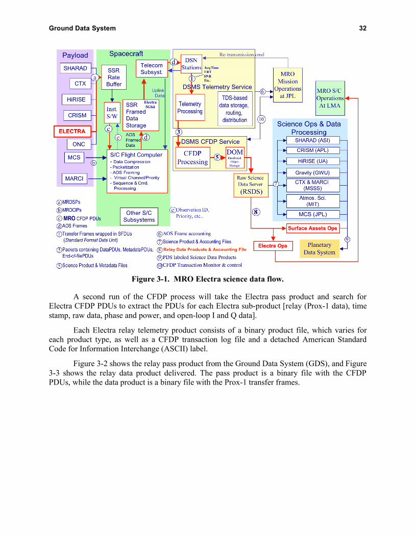
Ground Data System 32
Figure 3-1. MRO Electra science data flow.
A second run of the CFDP process will take the Electra pass product and search for
Electra CFDP PDUs to extract the PDUs for each Electra sub-product [relay (Prox-1 data), time
stamp, raw data, phase and power, and open-loop I and Q data].
Each Electra relay telemetry product consists of a binary product file, which varies for
each product type, as well as a CFDP transaction log file and a detached American Standard
Code for Information Interchange (ASCII) label.
Figure 3-2 shows the relay pass product from the Ground Data System (GDS), and Figure
3-3 shows the relay data product delivered. The pass product is a binary file with the CFDP
PDUs, while the data product is a binary file with the Prox-1 transfer frames.

Ground Data System 33
Figure 3-2. Electra relay pass product output from GDS.
Figure 3-3. Electra relay data product from GDS.

34
Section 4
X-Band Telecom Operations
4.1 Cruise Calibrations
Planned telecom cruise calibrations are summarized in Table 4-1. During the X-band and
Ka-band HGA calibration, the spacecraft articulates the HGA through a grid-like pattern (raster
scan) about the pre-launch antenna boresight. By monitoring the received signal strength, the
calibration determines if the HGA phase center has shifted during launch.
4.2 MOI Telecom Configurations
The main engine burn for MOI began at 21:24 universal time coordinated (UTC)
referenced to Earth received time (ERT), the time this event was seen on the Earth. Ninety
minutes prior to this, the telecom path was switched to LGA1, which then was used throughout
the orbit insertion process. Thirteen minutes prior to engine start, the spacecraft began a slew to
MOI attitude. It ended the slew 5 minutes before engine start, and its inertial attitude remained
fixed at this position throughout MOI. At the beginning of the burn, LGA1 was boresighted at
Earth. By the time MRO entered solar eclipse (start + 21 minutes) and was occulted from Earth
by Mars (2 minutes later), the off-boresight angle was around 20 to 25 deg. The burn ended at
21:51 ERT; the turn back to Earth ended at 22:13; and occultation ended (downlink reached the
Earth) at 22:16 ERT.
During the MOI itself, the DSN supported downlink telemetry with two 70-m antenna
stations simultaneously (DSS 14 and DSS 63 had overlapping coverage). Figure 4-1 shows the
approximate elevation angles for the 70-m antennas on March 10, 2006.
Table 4-1. Telecom cruise calibrations.
Calibration type Date Comments
X-band LGA performance Launch + 9 days Perform as part of normal
LGA ops. Spacecraft
slewing not required.
X-band HGA pattern calibration Launch + 24 days Raster scan; simultaneous
with Ka-band HGA
calibration
Ka-band HGA pattern calibration Launch + 24 days
Electra UHF pattern characterization Launch + 40 days Conical scan
Electra UHF performance Launch + 40 days
X-band Delta DOR checkout Launch + 40 days Done once per week,
starting at L+40d
Ka-band wideband delta-DOR
checkout
Launch + 40 days Done once per week,
starting at L+40d

X-Band Telecom Operations 35
10
20
30
40
50
60
70
80
90
12:00
AM
1:30
AM
3:00
AM
4:30
AM
6:00
AM
7:30
AM
9:00
AM
10:30
AM
12:00
PM
1:30
PM
3:00
PM
4:30
PM
6:00
PM
7:30
PM
9:00
PM
10:30
PM
12:00
AM
Time
Sta
tio
n E
lev
ati
on
An
gle
, d
eg
DSS 63 Madrid
DSS 43 Canberra
DSS 14 Goldstone
Figure 4-1. Station elevation angles on MOI day (exit occultation 22:16 UTC).
Following re-acquisition with LGA1, the X-band system was transitioned back to the
HGA for spacecraft checkout. Navigation began to collect two-way radiometric data and to
perform orbit determination of the capture orbit.
4.3 Aerobraking Telecom Configurations
During aerobraking, the two main activities are the drag passes and the aerobraking
maneuvers (ABMs). The drag passes occur at the capture orbit perigee, and the spacecraft is
oriented with the velocity vector in order to maximize the drag coefficient. The ABMs typically
are conducted at the apogee of the capture orbit and are used to adjust the orbit after the drag
pass if needed.
At 16 minutes prior to the start of each drag pass, an onboard sequence configures the
telecom system to transmit a carrier-only downlink over LGA1. In addition, the uplink bit rate is
switched to 7.8125 bps, the minimum available rate. After 1 minute for the DSN to lock up to the
carrier, the HGA is locked into position and communications are through LGA1 throughout the
duration of the drag pass. Ten minutes after the end of the drag pass, the sequence restores
nominal downlink through the HGA.
Likewise, 16 minutes before the beginning of the ABM, the sequence configures the
telecom system to transmit a carrier-only downlink through LGA1. This remains the telecom
configuration until 15 minutes after the conclusion of the ABM, at which time the nominal
downlink through the HGA is re-established.
4.4 Downlink Telemetry Modulation and Coding
The MRO project data volume goal for full mission success is to return over 26 terabits
of science data from Mars during its primary science phase, which exceeds any previous deep-
space mission by more than an order of magnitude.

X-Band Telecom Operations 36
The following kinds of modulation are used on MRO:
• BPSK on a subcarrier, with the subcarrier modulating the carrier
• BPSK directly on the carrier
• QPSK directly on the carrier
QPSK modulation capability by the SDST allows for twice the data rate to be transmitted
through the same bandwidth as compared with the BPSK used in previous missions. Sequential
tone ranging isn’t possible with QPSK because of the fully suppressed carrier.
Error-correcting codes as defined in Tables 4-2 through 4-7 are used on the downlink to
the DSN. The table referenced in the title of each subsection summarizes the main MRO
configuration items (bit rate and symbol rate, modulation type, modulation index, and station
receiver loop type) and receiver thresholds.
In the following subsections, the symbol rate is defined as the output of the SDST (i.e.,
channel symbols), and the information bit rate is defined as the frame bit rate coming into the
C&DH (at point ‘d’ in Fig. 3-1).
4.4.1 Short Frame Concatenated (Table 4-2)
The [(7,1/2) convolutional + Reed–Solomon (RS) (short frame)] concatenated code will
be used only for the emergency mode, 34.38 bps and a MOI data rate of 139 bps. The 34.38 bit
rate is chosen for heritage reasons, with the coded bit rate out of the C&H uplink–downlink
(ULDL) card at 40 bps and the SDST output symbol rate at 80 symbols per second (sps).
Table 4-2. Emergency mode (7,1/2) + RS (short frame) concatenated code.
TLM only TLM +
RNG Lo
TLM +
RNG HiCode Type Framed Bit
Rate, bps
Symbol
Rate, sps
Modulation
Type
Subcarr
Freq
(kHz)
Tlm Mod
Index
(deg)
Carrier
Loop Type
Threshold
Pt/No
(dB-Hz)
Threshold
Pt/No
(dB-Hz)
Threshold
Pt/No
(dB-Hz)
(7,1/2)+RS
(I=1) 34.4 80
Squarewave
Subcar 25 58 Residual 21.4 21.7 22.5
(7,1/2)+RS
(I=1) 137.5 320
Squarewave
Subcar 25 71 Residual 26.2 26.5 27.3
4.4.2 Long Frame Concatenated (Table 4-3)
The [(7,1/2) convolutional + RS (long frame)] concatenated code has been proven in
many prior missions and is used to cover the largest span of bit rates. Because of bandwidth
limitations, the maximum rate for the concatenated code downlink is a bit rate of 3.3 Mbps at the
SDST input and a symbol rate of 6.6 megasymbols per second (Msps) at the SDST output. If
interference with another project is an issue, maximum rates are 2 Mbps and 4 Msps.

X-Band Telecom Operations 37
Table 4-3. (7,1/2) + RS (long frame) concatenated code.
TLM only TLM +
RNG Lo
TLM +
RNG HiCode Type Framed Bit
Rate, bps
Symbol
Rate, sps
Modulation
Type
Subcarr
Freq
(kHz)
Tlm Mod
Index
(deg)
Carrier
Loop Type
Threshold
Pt/No
(dB-Hz)
Threshold
Pt/No
(dB-Hz)
Threshold
Pt/No
(dB-Hz)(7,1/2)+RS
(I=5) 556.9 1280
Squarewave
Subcar 25 72 Residual 31.2 31.5 32.3
(7,1/2)+RS
(I=5) 1740.4 4000
Squarewave
Subcar 25 72 Residual 36.0 36.3 37.1
(7,1/2)+RS
(I=5) 27846.8 64000
Squarewave
Subcar 375 72 Residual 47.9 48.2 49.0
(7,1/2)+RS
(I=5) 87021.1 200000
Squarewave
Subcar 375 72 Residual 52.8 53.1 53.9
(7,1/2)+RS
(I=5) 139233.8 320000
BPSK Direct
Mod None 72 Residual 54.9 55.2 55.9
(7,1/2)+RS
(I=5) 208850.7 480000
BPSK Direct
Mod None 72 Residual 56.6 56.9 57.7
(7,1/2)+RS
(I=5) 348084.4 800000
BPSK Direct
Mod None 72 Residual 58.8 59.1 59.9
(7,1/2)+RS
(I=5) 696168.9 1600000
BPSK Direct
Mod None 72 Residual 61.8 62.2 63.6
(7,1/2)+RS
(I=5) 1044253.3 2400000 QPSK None 82 Suppressed 63.4 - -
(7,1/2)+RS
(I=5) 1305316.7 3000000 QPSK None 82 Suppressed 64.3 - -
(7,1/2)+RS
(I=5) 478616.1 1100000
BPSK Direct
Mod None 72 Residual 60.2 60.6 62.0
(7,1/2)+RS
(I=5) 1740422.2 4000000 QPSK None 82 Suppressed 65.6 - -(7,1/2)+RS
(I=5) 2610633.3 6000000 QPSK None 82 Suppressed 67.3 - -
4.4.3 Turbo Code (Tables 4-4 Through 4-6)
Turbo codes are to be used for bit rates above 32 kbps. This capability, implemented in
C&DH hardware, provides more link margin as compared with convolutional codes of the same
code rate. Currently the maximum decode rate of the ground turbo decoder limits use of turbo
codes to 1.6 Mbps and below. If interference to another project could occur, the limit is 4 Msps
(SDST output channel rate).
Table 4-4. Turbo code, rate 1/2.
TLM only TLM +
RNG Lo
TLM +
RNG HiCode Type Framed Bit
Rate, bps
Symbol
Rate, sps
Modulation
Type
Subcarr
Freq
(kHz)
Tlm Mod
Index
(deg)
Carrier
Loop Type
Threshold
Pt/No
(dB-Hz)
Threshold
Pt/No
(dB-Hz)
Threshold
Pt/No
(dB-Hz)
Turbo 1/2 745645.4 1500000
BPSK Direct
Mod None 72 Residual 60.7 61.1 62.5
Turbo 1/2 1491290.8 3000000 QPSK None 82 Suppressed 63.5 - -
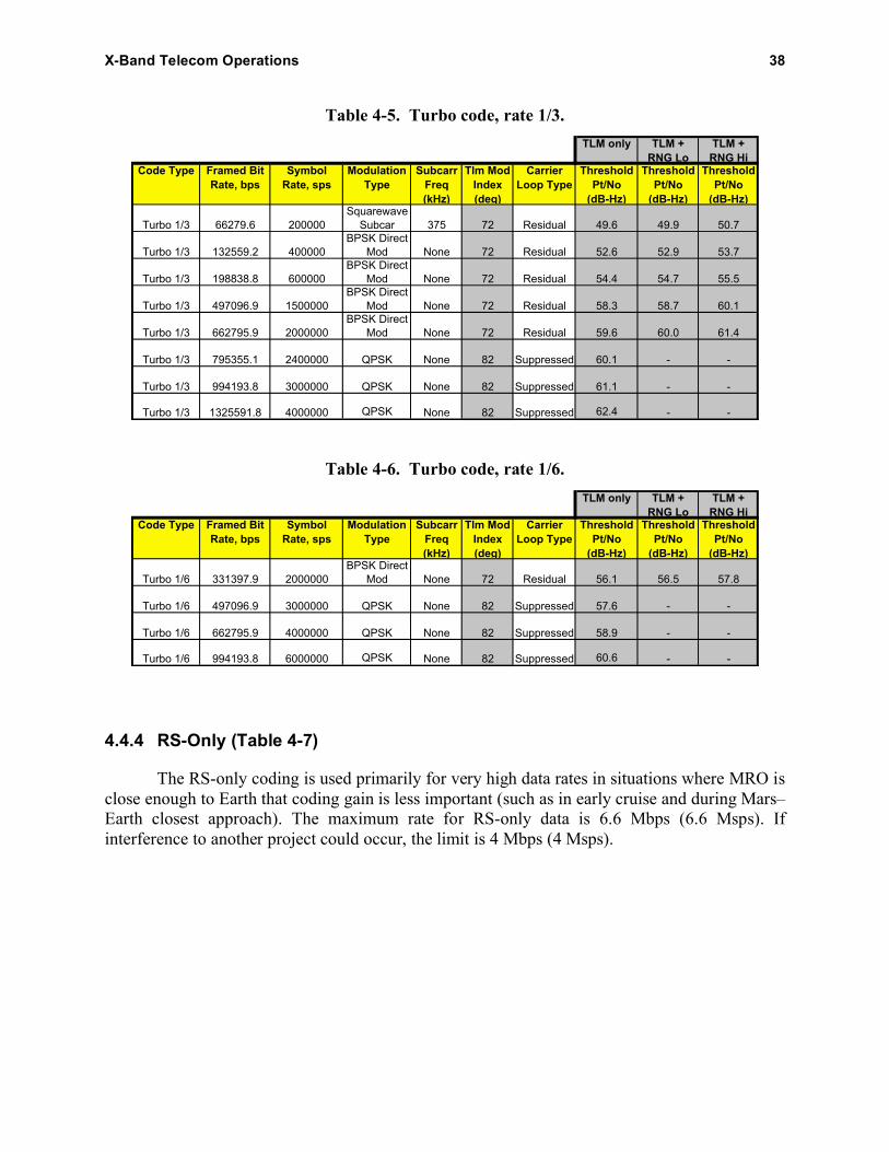
X-Band Telecom Operations 38
Table 4-5. Turbo code, rate 1/3.
TLM only TLM +
RNG Lo
TLM +
RNG HiCode Type Framed Bit
Rate, bps
Symbol
Rate, sps
Modulation
Type
Subcarr
Freq
(kHz)
Tlm Mod
Index
(deg)
Carrier
Loop Type
Threshold
Pt/No
(dB-Hz)
Threshold
Pt/No
(dB-Hz)
Threshold
Pt/No
(dB-Hz)
Turbo 1/3 66279.6 200000
Squarewave
Subcar 375 72 Residual 49.6 49.9 50.7
Turbo 1/3 132559.2 400000
BPSK Direct
Mod None 72 Residual 52.6 52.9 53.7
Turbo 1/3 198838.8 600000
BPSK Direct
Mod None 72 Residual 54.4 54.7 55.5
Turbo 1/3 497096.9 1500000
BPSK Direct
Mod None 72 Residual 58.3 58.7 60.1
Turbo 1/3 662795.9 2000000
BPSK Direct
Mod None 72 Residual 59.6 60.0 61.4
Turbo 1/3 795355.1 2400000 QPSK None 82 Suppressed 60.1 - -
Turbo 1/3 994193.8 3000000 QPSK None 82 Suppressed 61.1 - -
Turbo 1/3 1325591.8 4000000 QPSK None 82 Suppressed 62.4 - -
Table 4-6. Turbo code, rate 1/6.
TLM only TLM +
RNG Lo
TLM +
RNG HiCode Type Framed Bit
Rate, bps
Symbol
Rate, sps
Modulation
Type
Subcarr
Freq
(kHz)
Tlm Mod
Index
(deg)
Carrier
Loop Type
Threshold
Pt/No
(dB-Hz)
Threshold
Pt/No
(dB-Hz)
Threshold
Pt/No
(dB-Hz)
Turbo 1/6 331397.9 2000000
BPSK Direct
Mod None 72 Residual 56.1 56.5 57.8
Turbo 1/6 497096.9 3000000 QPSK None 82 Suppressed 57.6 - -
Turbo 1/6 662795.9 4000000 QPSK None 82 Suppressed 58.9 - -
Turbo 1/6 994193.8 6000000 QPSK None 82 Suppressed 60.6 - -
4.4.4 RS-Only (Table 4-7)
The RS-only coding is used primarily for very high data rates in situations where MRO is
close enough to Earth that coding gain is less important (such as in early cruise and during Mars–
Earth closest approach). The maximum rate for RS-only data is 6.6 Mbps (6.6 Msps). If
interference to another project could occur, the limit is 4 Mbps (4 Msps).

X-Band Telecom Operations 39
Table 4-7. RS coding only (long frame).
TLM only TLM +
RNG Lo
TLM +
RNG HiCode Type Framed Bit
Rate, bps
Symbol
Rate, sps
Modulation
Type
Subcarr
Freq
(kHz)
Tlm Mod
Index
(deg)
Carrier
Loop Type
Threshold
Pt/No
(dB-Hz)
Threshold
Pt/No
(dB-Hz)
Threshold
Pt/No
(dB-Hz)
RS only (I=5) 130531.7 150000
Squarewave
Subcar 375 72 Residual 58.2 58.5 59.3
RS only (I=5) 1740422.2 2000000
BPSK Direct
Mod None 72 Residual 69.5 69.9 71.2
RS only (I=5) 2088506.6 2400000 QPSK None 82 Suppressed 70.0 - -
RS only (I=5) 2393080.5 2750000 QPSK None 82 Suppressed 70.6 - -
RS only (I=5) 2610633.3 3000000 QPSK None 82 Suppressed 71.0 - -
RS only (I=5) 2871696.6 3300000 QPSK None 82 Suppressed 71.4 - -
RS only (I=5) 3480844.4 4000000 QPSK None 82 Suppressed 72.3 - -
RS only (I=5) 5221266.6 6000000 QPSK None 82 Suppressed 74.0 - -
4.5 X-Band Link Performance Summaries
The following link performance summaries for command (Figures 4-2 and 4-3) and
telemetry (Figures 4-4 and 4-5) come from [3]. The ratio of total power to noise spectral density,
Pt /N0, thresholds include a 3-dB margin. The design control tables as well as plots for
radiometric (Doppler and ranging) capabilities are included in [3].

X-Band Telecom Operations 40
Figure 4-2. X-band HGA uplink Pt /N0 profile and command supportability.
Figure 4-3. X-band LGA1 uplink Pt /N0 profile and command supportability.
Pt/
No
, d
B-H
z

X-Band Telecom Operations 41
Figure 4-4. X-band HGA downlink Pt /N0 profile and telemetry supportability.
Figure 4-5. X-band LGA1 downlink Pt /N0 profile and telemetry supportability.
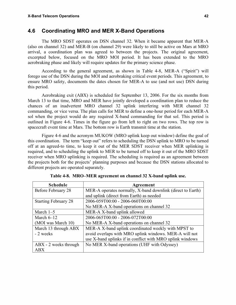
X-Band Telecom Operations 42
4.6 Coordinating MRO and MER X-Band Operations
The MRO SDST operates on DSN channel 32. When it became apparent that MER-A
(also on channel 32) and MER-B (on channel 29) were likely to still be active on Mars at MRO
arrival, a coordination plan was agreed to between the projects. The original agreement,
excerpted below, focused on the MRO MOI period. It has been extended to the MRO
aerobraking phase and likely will require updates for the primary science phase.
According to the general agreement, as shown in Table 4-8, MER-A (“Spirit”) will
forego use of the DSN during the MOI and aerobraking critical event periods. This agreement, to
ensure MRO safety, documents the dates chosen for MER-A to use (and not use) DSN during
this period.
Aerobraking exit (ABX) is scheduled for September 13, 2006. For the six months from
March 13 to that time, MRO and MER have jointly developed a coordination plan to reduce the
chances of an inadvertent MRO channel 32 uplink interfering with MER channel 32
commanding, or vice versa. The plan calls for MER to define a one-hour period for each MER-A
sol when the project would do any required X-band commanding for that sol. This period is
outlined in Figure 4-6. Times in the figure go from left to right on two rows. The top row is
spacecraft event time at Mars. The bottom row is Earth transmit time at the station.
Figure 4-6 and the acronym MUKOW (MRO uplink keep out window) define the goal of
this coordination. The term “keep out” refers to scheduling the DSN uplink to MRO to be turned
off at an agreed-to time, to keep it out of the MER SDST receiver when MER uplinking is
required, and to scheduling the uplink to MER to be turned off to keep it out of the MRO SDST
receiver when MRO uplinking is required. The scheduling is required as an agreement between
the projects both for the projects’ planning purposes and because the DSN stations allocated to
different projects are operated separately.
Table 4-8. MRO–MER agreement on channel 32 X-band uplink use.
Schedule Agreement
Before February 28 MER-A operates normally, X-band downlink (direct to Earth)
and uplink (direct from Earth) as needed
Starting February 28 2006-059T00:00 - 2006-060T00:00
No MER-A X-band operations on channel 32
March 1–5 MER-A X-band uplink allowed
March 6–12
(MOI was March 10)
2006-065T00:00 - 2006-072T00:00
No MER-A X-band operations on channel 32
March 13 through ABX
- 2 weeks
MER-A X-band uplink coordinated weekly with MPST to
avoid overlaps with MRO uplink windows. MER-A will not
use X-band uplinks if in conflict with MRO uplink windows
ABX - 2 weeks through
ABX
No MER X-band operations (UHF with Odyssey)

X-Band Telecom Operations 43
SC
ET
note
: MR
O S
CE
T an
d S
pirit
S
CE
T ar
e no
t exa
ctly
equ
ival
ent
MR
O U
/L
keep
out
= 49
min
owlt
11 m
in6:
25 m
in
Ear
th T
rans
mit
Tim
e
Spi
rit:
“Sta
te 1
tim
eout
”
Spi
rit S
wee
p
+ 2
min
m
argi
np
ad
Spi
rit D
SN
tra
nsm
itter o
n
Spi
rit C
omm
andi
ng
Spi
rit
com
man
ding
sto
p/
DS
N tr
ansm
itter
off (
nom
inal
)
MR
O:
“sta
te 1
tim
eout
”
MR
O D
SN
tra
nsm
itter o
n
MR
O
swee
p
11 m
in
Spi
rit c
omm
andi
ng
star
ts
20 m
in o
f com
man
ding
20 m
in o
f com
man
ding
pad
Spi
rit: L
ast
poss
ible
DS
N
trans
mitte
r off
time
9 m
in
20 m
in:
“sta
te o
ne tim
eout
”/sw
eep
20 m
in:
“sta
te o
ne tim
eout
”/sw
eep
20 m
in
tota
l MR
O D
SN
tran
smitt
er o
ff tim
e =
60 m
in
MR
O D
SN
tra
nsm
itter o
ff
2:35
min
Fig
ure
4-6
. M
RO
up
lin
k k
eep
ou
t w
ind
ow
(M
UK
OW
) ti
min
g.

X-Band Telecom Operations 44
Every two weeks, MER delivers a spreadsheet file with two entries in each row: (1) the
time the DSN transmitter supporting MRO is to be turned off and (2) the time the DSN
transmitter subsequently supporting MER-A is to be turned off. The MER and MRO SDSTs
have a “State 1 timeout” duration of 10 minutes between when the SDST receiver goes one way
(in response to the station transmitter turn off) and when it forces its phase-locked loop (PLL) to
best-lock frequency. Each project uses a “sweep acquisition” uplink frequency profile by the
station to ensure the station’s uplink carrier goes through the actual (temperature-dependent)
best-lock frequency.
The coordination process, as developed on a basic weekly schedule, allows for negotiated
updates (including cancellations or additions) of keep-out times to meet significant needs of
either project. These could include changes in MRO aerobraking times or anomalies that occur
with either project.
Although the agreement primarily affects uplink operations, both MER spacecraft
occasionally require a direct-to-Earth (DTE) X-band downlink for onboard spacecraft clock
correlation with UTC. Also, both MER spacecraft rely on the detection by the DSN station of an
unmodulated X-band downlink carrier (“beep”) to verify the success of the “in the blind” direct-
from-Earth (DFE) command session and the consequent hand off by flight software to the new
sol’s master sequence.8
Successful lock-up of MER DTE passes requires coordination with MRO because the
MRO downlink signal level is much greater than the MER HGA DTE downlink. When MER-A
needs to do a DTE, it needs to use a specific communications mode (504 bps or lower on a
25-kHz subcarrier, (7,1/2) convolutional code). During the time of the MER-A downlink, MRO
needs to reduce its telemetry rate and be on the USO (achieved by the MUKOW ground
transmitter coordination).
For a MER-B (“Opportunity”) DFE uplink (three channels away), MRO can continue its
normal uplink. During the time of a MER-B downlink (three channels away), it has been
recommended that the coordination include the absence of uplink ranging modulation to MRO.
This is achieved by defining the station configuration for the MRO pass to not include ranging.
8 MER beep detection does not require any special MRO configuration or action. It does require (for both MER-A
and MER-B) that the station tracking MER narrow the receiver’s fast fourier transform (FFT) in both bandwidth and
signal level range to reduce the effects of MRO spectral components near the beep frequency. The beep frequency is
precisely known because the beep is two-way coherent with the uplink.

45
Section 5
Ka-Band Operational Demonstration
5.1 Ka-Band Operational Demonstration Overview
The motivation for verifying the operational use of Ka-band is to achieve increased
available bandwidth and, therefore, a higher available data rate. The deep-space allocation at X
band (8.4–8.45 GHz) is 50 MHz, and that at Ka-band (31.8–32.3 GHz) is 500 MHz. However,
weather effects cause much larger fluctuations on Ka-band than on X-band. This characteristic
makes the traditional link design for data return power inefficient for Ka-band. The traditional
method involves a single downlink rate per pass and assigns a margin sufficient to provide a
required data availability and to overcome a defined weather-effects severity. The margin is
larger than required most of the time. By testing the operational use of Ka-band, MRO may
demonstrate the potential for greater average data rate using a concept of operations requiring
significantly less power for the same total data volume. Several variations of this concept [11]
use optimization techniques involving multiple data rates during a tracking pass. The rate-
selection criteria account for the station elevation-angle profile as well as the distance of the
spacecraft to Earth during each pass.
The MRO test is in the form of a telecommunications technology demonstration. The
purpose of the demonstration is to develop operational procedures specific for Ka-band that
account for the weather variations and are still compatible with the way the MRO flight team
sequences the spacecraft. The demonstration will involve the use of data rate (and coding and
modulation index) selection algorithms with input from time-variable weather models (and
possibly forecasts). On the ground, the MRO cruise mission phase has already shown how the
ability to point the station antenna accurately enough and to monitor signal-to-noise ratio and
system noise temperature are factors to be resolved in order to determine the operational
feasibility of using Ka-band for future missions.
The Ka-band experiment team will characterize and create or update models of Ka-band
link performance. Some of the factors the demonstration will consider are
• The accuracy of existing Ka-band models
• Effects of weather forecasting/predicting on Ka-band telemetry
• Benefits of data-rate optimization during Ka-band passes
• Ka-band link performance during solar conjunction
• Differences in ranging and Doppler performance between X-band and Ka-band
5.2 Ka-Band Link Prediction and Performance During Cruise
MRO and four 34-m BWG stations participated in a total of 10 passes dedicated to Ka
band during cruise. All three sites participated. DSS 25, DSS 34, and DSS 55 each had three
passes, and DSS 26 had one.

Ka-Band Operational Demonstration 46
In addition to the 10 dedicated passes, there were two periods of “shadow” passes, the
first from November 14 to November 20, 2005, around TCM-2, and the second from December
26 to January 4, 2006, during a gravity calibration.
Figure 5-1 shows a downlink Pt /N0 profile for the Ka-band operational demonstration
using DSS 25 in the X-/Ka-band configuration as the ground station antenna. The maximum
Ka-band data rate achievable throughout the entire mission, with a 3-dB margin, is 331 kbps.
In fact, a wide variety of data rates and modes was used during cruise. These were
changed by the background sequence, with modulation index also changed by real-time
command, as described in the next section. To simulate the occultation of MRO by Mars and to
verify the ability of the stations to reacquire the Ka-band downlink, the Ka-band TWTA was
turned off and back on.
During the dedicated pass on October 7, 2005, DSS 25 decoded turbo-coded data from
the Ka-band downlink for the first time. During the pass on October 31, DSS 55 received a total
of 133 Gbits from Ka-band, at rates as high as 6 Mbps; these represent the largest data volume
and the highest data rate from deep space to date.
In the critical area of station antenna pointing, the best performance to date has been with
DSS 34, which consistently achieved 4- to 5-mdeg blind-pointing error according to the
monopulse system’s correction offsets. It appears that DSS 34 has the best sky models for blind-
pointing in the regions for MRO during cruise.
Figure 5-1. Ka-band HGA downlink Pt /N0 profile and telemetry supportability.
Pt/
No
, d
B-H
z

Ka-Band Operational Demonstration 47
The MRO Ka-band team demonstrated functionality and characterized at both bands the
performance of the radiometric data types used for navigation and radio science. Two-way
Doppler and ranging performance (both downlink bands using the X-band uplink) were
comparable at X-band and Ka-band and met or exceeded project requirements.
The two sets of shadow passes operated with both X-band and Ka-band set for 550 kbps
RS and (7,1/2) convolutional concatenated coding. Table 4-3 shows the information rate was
~480 kbps in this mode, and the SDST output symbol rate was 1.1 Msps. Ranging was off for
Ka-band in the first set of shadow passes and at 17.5-deg modulation index for the second set.
The station monopulse system (not required for X-band) was not used in the first set of shadow
passes, but was tried for some of the passes in the second set.
Significant findings from the cruise tests included the following:
• Ka-band SNT measurements are sufficiently accurate, when the monopulse works, at
signal levels corresponding to the shortest Earth–Mars distance.
• The MRO Ka-band system (35-W RF) can outperform the X-band system (100-W
RF) when the weather is good, as shown in Figure 5-2 [10].
The lessons learned section describes some of the other findings from the cruise tests.
5.3 Spacecraft Constraints and Operational Factors
Considering one link (X-band or Ka-band) at a time, the codes available in the C&DH are
• Turbo codes with block length 8920 bits and rates 1/2, 1/3, and 1/6
• (255,223) RS block code
Figure 5-2. Comparison of Ka-band and X-band telemetry (DSS 34, December 26, 2005).

Ka-Band Operational Demonstration 48
The SDST can concatenate a (7,1/2) convolutional code on the RS, making a third coding
type available.
The C&DH imposes the following limits on the coding and data rates available to the
demonstration. The channel symbol rate is defined at the SDST output, so these limits refer to
convolutional code symbols for the concatenated code.
• If the X-band and Ka-band downlinks have different data types (carry non-identical
data streams), one has to use turbo coding and the other has to use RS coding.
• If X-band and Ka-band carry different data types, the combined channel symbol rate
of the two bands should not exceed 6 Msps.
• If both bands carry identical data, the symbol rate on each band cannot exceed
6 Msps.
The ground turbo decoder limits the rate 1/2 code to a maximum bit rate of 1.5 Mbps.
At Mars, to minimize interference, X-band uses QPSK modulation for symbol rates
higher than 2 Msps. For Ka-band, BPSK modulation is always used.
During the prime science mission, the MRO mission plan allocates the Ka-band
demonstration two passes per week and one delta-DOR pass a month. The SDST allows for
independently configurable telemetry subcarrier frequencies and modulation index values,
independent control of DOR (on/off), turnaround ranging (on/off), and ranging modulation
index.
The operations concept that the demonstration plans to validate is based on maximizing
the average data return subject to minimum availability. Three different scenarios will be
evaluated [11]:
• Nominal link operations using link designs (predictions) based on long-term monthly
or weekly statistics
• Link operations using short-term forecasts
• Link operations during superior solar conjunction
The spacecraft is normally sequenced through two different procedures: background
sequencing and mini-sequencing [10]. The approved sequence represents the onboard
programming that controls subsystem configuration and operation. In addition, real-time
commands can be used to change simple functions such as Ka-band modulation index. Use of
real-time commands is very limited because of possible interaction with the planned sequences
that must be validated before being uploaded.
Background sequencing programs the spacecraft for 28 days, and a background sequence
goes through a 28-day cycle to design, test, and upload. Mini-sequencing programs the
spacecraft for specific events such as instrument calibrations or trajectory correction maneuvers.
A second important use of the mini-sequence is to modify the executing background sequence
according to later information available to the project. The development cycle for mini-
sequences can vary somewhat, but they usually take a week. With mini-sequencing, MRO

Ka-Band Operational Demonstration 49
Ka-band telecom parameters, such as data rate profile and modulation index, can be changed
weekly rather than monthly [11].
The lead time for MRO sequencing means that it’s a challenge to incorporate very short
term (1–2 days) weather forecasting into any Ka-band operational concept. It’s expected during
the primary science mission that almost all Ka-band activities will be controlled with the 28-day
background sequence. The Ka-band link’s data rate and modulation index could be changed
according to the background sequence.
5.4 Cruise Delta-DOR Operations and Performance
At X-band, the technique of delta differential one-way ranging (delta-DOR) has proved
to be valuable for supporting deep-space cruise navigation, especially for missions with tight
targeting requirements at Mars [10]. To make a delta-DOR measurement, a very long baseline
interferometry (VLBI) system at each of two stations makes high rate recordings of signals from
the spacecraft and angularly nearby radio sources. Driven by a sequence of events called the
DSN Keywords File, the antennas at both stations point alternately, every few minutes, at the
spacecraft and at the radio source in synchronism as the recordings are made. The radio source
observations calibrate the system. For each source, the difference in signal arrival time between
stations is determined and delivered to the navigation team, constituting the measurement.
Operational X-band measurements are specified to provide an angular position accuracy of
2.5 nrad [13].
The wider spectrum allocation at Ka-band can enable an advance in delta-DOR accuracy.
To achieve a substantial improvement in accuracy at Ka-band, it will be necessary to improve
antenna-pointing performance at the ground stations, increase the frequency of the DOR tone at
Ka-band, increase the sample rate for the VLBI data recordings, and continue work on surveying
radio sources at Ka-band.
Several preparations were necessary for Ka-band:
• Radio source flux surveys were made by the National Radio Astronomy Observatory
(NRAO) at 24 GHz and 43 GHz.
• The VLBI receiver’s front-end bandwidth was widened to accommodate the
±76 MHz spanned by the MRO DOR tones.
• Initial models for station antenna “blind-pointing” were developed for pointing to the
radio sources where monopulse couldn’t be used.
Data at X-band and Ka-band were acquired for seven delta-DOR passes during MRO cruise.
Except for a few radio source observations that were degraded due to known ground station
pointing problems, the measurement accuracy at Ka-band was comparable to the accuracy at
X-band and within expectations. The factor of four increase in the DOR tone frequency for MRO
at Ka-band relative to X-band was just enough to offset the lower SNR for sources at Ka-band
relative to X-band.

Ka-Band Operational Demonstration 50
5.5 Nominal Ka-Band Link Operation During the Science Mission
The Ka-band demonstration during the prime science mission will incorporate link design
techniques that attempt to maximize the average link capacity with respect to a given
atmospheric noise temperature distribution [11]. The distribution could be based on long-term
statistics (more natural for monthly background sequencing) or on short-term forecasts (leading
to weekly mini-sequence updates).
There are several limitations in sequencing capability, onboard C&DH capability, and
station decoder speed that affect the link design implementation:
• MRO has a limited number of channel symbol rates and a limited number of
modulation index values.
• To reduce sequence complexity, the number of data rates included in the profile for
each pass would be limited to two. The effect of this limitation is found to be small.
• The ground turbo decoder processing speed limits the maximum decoded data rate to
1.5 Mbps.
The process for establishing the set of data rates and their associated minimum “threshold” Pt /N0
values is as follows:
• The bit-error rate (BER) at threshold is set at 10–6
.
• For each data rate, the best code (requiring the lowest ratio of energy per bit to noise
spectral density (Eb/N0), for a 10–6
BER) is selected that fits within the C&DH and
decoder limitations.
• For that rate and that code, the modulation index is selected that results in the lowest
required Pt /N0.
Table 5-1 shows the results of this constrained optimization for coding type. Tables 4-3 through
4-7 show the threshold Pt /N0 values for each MRO data rate.
The Ka-band demonstration experiment plan, summarized in [11], defines four possible
optimization techniques that are based on the number of data rates to be considered during a
single pass, and the minimum required link availability. An availability of 90%, for example,
means that the link performance (symbol SNR for example) will be above the threshold 90% of
the pass duration. Availability is a function of the atmospheric noise temperature distribution at
the site. The plan is to use different distributions at different times of the year to reflect the
effects of seasonal changes on the capacity of the link.
The optimizations have been made for the varying Mars–Earth range and declination of
Mars through the primary science mission. As the declination changes, the view period duration
at each DSN site changes as well. View period duration is the time from when Mars reaches a
10-deg elevation angle at rise until it reaches 10 deg at set. View periods were used in the
optimizations because specific station passes had yet to be allocated.
During the mission, an algorithm called DR-90 (for dual rate, or two rates per pass, and
90% availability) will be used to determine the data-rate profile for the allocated passes at the

Ka-Band Operational Demonstration 51
Table 5-1. Optimized MRO coding type versus bit rate for Ka-band demonstration.
Data rate Coding
333 kbps, 500 kbps, 667 kbps, and 1 Mbps (8960,1/6) turbo code
1.33 Mbps (8960,1/3) turbo code
750 kbps and 1.5 Mbps (8960,1/2) turbo code
32 kbps, 1.74 kbps, and 2.61 Mbps (255,223), (7,1/2) concatenated code
2.87 Mbps, 3.48 Mbps, and 5.22 Mbps (255,233) Reed–Solomon only
beginning of each 28-day sequencing period, and these rates will be programmed as part of the
background sequence for the two Ka-band demonstration passes per week.
5.6 Solar Conjunction Experiments
Communications experiments are planned during the solar conjunctions that bracket the
primary science mission. These conjunctions are in October–November 2006 and November–
December 2008. The minimum Sun–Earth–probe (SEP) angles are 0.39 deg on October 23,
2006, and 0.46 deg on December 5, 2008.
The solar conjunction experiment will characterize solar charged-particle effects on the
Ka-band and X-band carrier and telemetry links. The primary objectives are
• To evaluate Ka-band performance as a function of SEP angle against the concurrent
X-band performance
• To measure any degradation to the link that occurs during solar coronal transient
activity, such as coronal mass ejections
A goal is to determine how low the SEP angle can possibly go (for each band) while
maintaining carrier lock and achieving reasonably reliable telemetry (with care given to
telemetry modulation index and station receiver loop bandwidth parameters).
Below 1 deg, the experiment includes testing simulated frequency shift-keying (FSK)
modulation using the carrier to demonstrate information flow at the equivalent of 1 bps.
The two experiment periods are from October 8 to November 7, 2006, when the SEP
angle is less than 5 deg, and similarly from November 18 to December 24, 2008. The planned
downlink mode for both frequency bands will be one-way with the USO as the frequency
reference. The prime station is DSS 25 at Goldstone, where the Earth weather (tropospheric)
effects should be minimal.
Solar effects are smaller at Ka-band than at X-band, so the advantage of using Ka-band is
known from previous in-flight experiments. An X-band link using BPSK begins to degrade near
a 2-deg SEP angle. Based on comparable solar effects, it’s believed that a Ka-band link would
begin to degrade somewhere near 1 deg. The MRO experiment is the first time it will be possible
to quantify solar effects on Ka-band telemetry.

52
Section 6
UHF Calibrations and Operations
6.1 UHF System Tests During Cruise
The Stanford test,9 on September 21 and 22, 2005, included first a single brief uplink test
to provide a very top level check of the MRO UHF receiver chain. For this test, the Stanford
klystron was operated at 30 kW maximum to generate an unmodulated uplink carrier at
401.6 MHz. A calibrated coupler at the output of the klystron was routed back to a power meter
to monitor and control the total output power.
The uplink test was the only test in full-duplex mode before the prime science mission
began. The test took 12 minutes, with operation at each level for 1 or 2 minutes. Klystron output
levels were changed in 3-dB steps down to –21 dB below 30 kW; then the klystron was turned
off for 1 minute, then back on at 4.8 dB, 0 dB, and 2 dB below 30 kW for final uplink
confirmation.
The remainder of the Stanford test was return link only, with Electra in the half-duplex
mode. This part of the test produced data for the UHF antenna patterns in Section 2. Test data
came from four conic cuts (at 10, 33, 48, and 60 deg from cruise nadir) for 401.6 MHz and 437.1
MHz. MRO was fixed at cruise attitude between the conic-cut rolls. The roll rate was 12 deg per
minute, resulting in a 30-minute roll for each cut.
6.2 Phoenix Support
The Phoenix mission is the first in NASA’s Mars Scout program, an initiative for smaller,
relatively lower-cost spacecraft to complement the major missions. The Phoenix mission is in
development for launch in August 2007 with landing in May 2008, about 75% of the way
through the MRO prime science phase. Phoenix is planned to land at the end of Martian spring in
icy soils inside the Martian Arctic Circle, near the north polar ice cap. Phoenix will spend up to
three months examining the history and current processes involving water ice in these soils,
analyzing the soil’s chemistry and mineralogy, and monitoring the polar climate.
Like the MER rover, the Phoenix lander carries the previous generation Prox-1 UHF
transceiver, the CE 505. Phoenix carries an X-band system for communication with the DSN
during interplanetary cruise. Planning for the Phoenix mission is based on UHF support by
MRO/Electra for EDL as well as for forward- and return-link relay services during its surface
mission.
9 This test used UHF transmitting and receiving equipment and an antenna at Stanford University, California,
operated by SRI International. The Stanford antenna aperture diameter is 45.7 m. Forward-link signal-level
telemetry, return-link power received at Stanford, the Stanford–MRO range from navigation, and the EUT transmit
power and spacecraft-attitude telemetry from the MRO were used to solve for MRO transceiver performance and
UHF antenna gain.

UHF Calibrations and Operations 53
For EDL, the Phoenix project wants to track the lander from cruise stage separation to
touchdown, using first open-loop data recording on MRO and Odyssey, followed by closed-loop
tracking on Odyssey. The telemetry begins at a rate of 8 kbps, followed by 32 kbps, as well as
one-way Doppler data throughout. Analysis of a reference landing site and arrival time for
Phoenix indicates that the EDL flight time from cruise stage separation is less than 15 minutes
and that MRO will be able to have good visibility for the entire time.
During the surface mission, the MRO mission plan states that Phoenix expects to request
two to three relay contacts daily10
with MRO’s Electra at rates of up to 128 kbps.
6.3 Mars Science Laboratory (MSL) Support
MSL is planned for launch in late 2009, with arrival at Mars in October 2010 near the end
of the primary MRO relay mission phase. Twice as long and three times as heavy as the Mars
Exploration Rovers Spirit and Opportunity, the Mars Science Laboratory would collect Martian
soil samples and rock cores and analyze them for organic compounds and environmental
conditions that could have supported microbial life now or in the past.
The top priority for MRO during the relay phase is communications support for other
missions, and the plan is for MRO to provide prime landed mission support to MSL. Specific
configurations and scenarios for MRO support of MSL are still under development.
Although the MRO primary relay mission ends in 2010, MRO carries enough propellant
for about 20 to 25 additional years of station keeping for relay operations. This estimate, based
on pre-aerobraking propulsion performance estimates, includes raising the spacecraft into a
higher orbit to satisfy planetary quarantine constraints. The extended mission orbit ranges from
about 350 km periapsis to 410 km apoapsis, as defined in the MRO extended mission plan.
Coordination of relay opportunities among surface assets such as MSL and orbiters such
as MRO will be performed by the MMO. Every 4 weeks, as part of the long-range coordination
process, the projects (including MRO) will provide ephemeris predictions, as well as known non-
relay periods, to MMO as part of the coordination process. On a weekly basis, for near-term
coordination planning, the MSL project will update this information and provide specific
“requested” overflights.
Relay activities are performed by MRO/Electra in the same manner during the primary
science and relay phases, but priorities are different:
• In the primary science phase, relay passes will be sequenced together with the science
data acquisition. However, critical relay activities receive priority in terms of timing
and resources. Non-critical relay activities are prioritized in conjunction with MRO
science investigations.
10
Because MRO will still be in its primary science mission, Odyssey is prime for Phoenix landed relay support, with
MRO as backup only. As backup, however, MRO needs to be ready to provide up to 3 contacts per day. The MRO
flight team, therefore, needs to plan for Phoenix forward and return data flow through MRO and test for Phoenix
landed operations. The tests would include preparation of MRO command sequences and data flow over operational
forward and return data paths between the MRO and Phoenix project support areas. MRO would also generate
information for and participate in Mars relay coordination meetings involving Phoenix.

UHF Calibrations and Operations 54
• The instruments and UHF antenna will continue to be pointed to nadir in the relay
phase. In this phase, however, the activities to support any scheduled relay pass are
prime and take priority over science activities. In the event of electromagnetic
interference (EMI) conflicts between other payloads and Electra, for example, the
conflicting payloads will be put into a mode to minimize the impact to Electra’s relay
pass performance.

55
Section 7
Lessons Learned
The initial MRO X-band and Ka-band lessons learned were documented in the MRO
Post-Launch Assessment Review (PLAR) [7], which was held in October 2005. Some of these
problems have subsequently been resolved or worked around. As the project documents
additional lessons, they will be included in updates of this article. There is also an updated
summary of issues raised in the MRO/MER coordination of X-band operations with both MRO
and MER-A on DSN channel 32. See the MER telecom article in this series for greater detail
[14].
7.1 X-Band
Earth Network Bandwidth (from DSN stations to JPL): While the MRO project
documented this concern in terms of the data- and time-intensive aerobraking mission phase, it
can be generalized to a lesson-learned as missions become more and more bandwidth intensive:
• The station-to-JPL link may be too slow to support aerobraking engineering and
primary science rates. The data links are provided by the NASA Integrated Services
Network (NISN).
• Computing power may not be sufficient to unwrap real-time engineering packets
during aerobraking.
• Reliable Network Service (RNS) at JPL may not be able to handle the full MRO
bandwidth.
The MRO requirements are as follows:
• The Deep Space Mission System (DSMS) shall provide the capability to ensure that a
version of a payload product set containing any data can be made available within 24
hours of receipt of the Earth receive time of that data.
• For the aerobraking phase, the project requests a guarantee of real-time data at a rate
of at least 220 kbps.
7.2 Ka-Band
In-Flight HGA Calibration: The first HGA calibration was performed over DSS 55 on
September 9, 2005. The calibration point spacing (1 deg by 1 deg) was too large to resolve the
Ka-band antenna pattern. The calculated Ka-band boresight had an error of 0.1 deg. This is
equivalent to an uncertainty (loss) in effective isotropic radiated power (EIRP) of 5 dB.
The received downlink Ka-band signal level was too high for a normally configured
station to measure the antenna pattern accurately.

Lessons Learned 56
Station antenna pointing errors and atmospheric effects could significantly affect the
calibration. Active measures to reduce or account for their impact are recommended.
7.3 UHF
Electromagnetic Interference (EMI) to the Electra receiver: While the EMI problem
was documented as a result of pre-launch testing, it has subsequently been confirmed in cruise
phase testing and remains a concern for the primary science phase and the relay phase.
The driving force behind the EMI specification is the exceptional low-signal-level
capability and the frequency agility of the Electra receiver. Electra is programmed to be able to
support data rates down to 1 kbps across a 60-MHz UHF frequency band of 390 MHz to
450 MHz. This corresponds to a threshold received signal level of about –140 dBm.
In addition to the threshold levels set by communications, the Electra carrier acquisition
and tracking functions are programmable and can be set to acquire and track very narrow band
(carrier-only) signals. Navigation proponents have talked of performing approach navigation
with signal levels down to –150 dBm to –160 dBm.
Pre-flight EMI tests showed that almost all unwanted MRO payload and MRO spacecraft
subsystem UHF output appeared as tones. Box level testing of various science payloads during
MRO development revealed interferers that produced tones exceeding a specification threshold
signal level of –140 dBm, with perhaps hundreds of tones in total. The tones have been identified
as harmonic overtones of switching power supplies, data buses, or clock mechanisms.
Workarounds, identified in the MRO/Electra operations handbook [15], include
• Use of a minimum data rate of 8 kbps (with a Prox-1 frame error rate of 1*10–3
)
• Restriction of the return-link mode to full-duplex operation at 401.585625 MHz

57
References
[1] Mars Reconnaissance Orbiter public homepage, Jet Propulsion Laboratory, Pasadena,
California. http://mars.jpl.nasa.gov/mro/
[2] R. Lock and R. Sharrow, MRO Mission Plan, Rev. C, JPL D-22239 (internal document),
Jet Propulsion Laboratory, Pasadena, California, July 2005.
[3] D. K. Lee, MRO Telecom Design Control Document, Rev. A, JPL D-22724 (internal
document), Jet Propulsion Laboratory, Pasadena, California, July 18, 2005.
[4] J. Taylor and D. Bell, “Mars Relay Description for Scout Proposals,’’ Jet Propulsion
Laboratory, Pasadena, California, April 2006,
http://mars-scout.larc.nasa.gov/PDF_FILES/Mars_Relay_Desc.pdf
[5] Consultative Committee for Space Data Systems, CCSDS 211.0-B-3 (Blue Book),
Recommendation for Space Data System Standards, “Proximity-1 Space Link Protocol—
Data Link Layer,” May 2004, http://public.ccsds.org/publications/BlueBooks.aspx
[6] Consultative Committee for Space Data Systems, CCSDS 211.1-B-2 (Blue Book),
Recommendation for Space Data System Standards, “Proximity-1 Space Link Protocol—
Physical Layer,” May 2004, http://public.ccsds.org/publications/BlueBooks.aspx
[7] MRO Post Launch Assessment Review, Jet Propulsion Laboratory, Pasadena, California,
October 4, 2005.
[8] C. H. Lee, K.-M. Cheung, C. Edwards, S. J. Kerridge, G. K. Noreen, and A. Vaisnys,
“Orbit Design Based on Global Maps of Telecom Metrics,” Aerospace 2005 IEEE
Conference, Big Sky, Montana, March 5–12, 2005.
[9] J. Hamkins and M. K. Simon, eds., Autonomous Software-Defined Radio Receivers for
Deep Space Applications, Chapter 2, “The Electra Radio,” E. Satorius, et al., John Wiley
& Sons, in press.
[10] S. Shambayati, et al., “Mars Reconnaissance Orbiter Ka-band (32 GHz) Demonstration:
Cruise Phase Operations,” AIAA SpaceOps 2006, Rome, Italy, June 18–23, 2006.
[11] S. Shambayati, et al., “Link Design and Planning for Mars Reconnaissance Orbiter
(MRO) Ka-band (32 GHz) Telecom Demonstration,” IEEE Aerospace Conference, Big
Sky, Montana, March 5–12, 2005.
[12] DSMS Telecommunications Link Design Handbook, Rev. E, JPL D-810-005, Jet
Propulsion Laboratory, Pasadena, California, August 25, 2006,
http://eis.jpl.nasa.gov/deepspace/dsndocs/810-005/
[13] J. S. Border, “2004 Error Budget for DSN Delta Differential One-Way Range
Measurement,” JPL Interoffice Memorandum 335-04-04-D (internal document), Jet
Propulsion Laboratory, Pasadena, California, July 9, 2004.

References 58
[14] J. Taylor, A. Makovsky, A. Barbieri, R. Tung, P. Estabrook, and A. G. Thomas, Mars
Exploration Rover Telecommunications, Jet Propulsion Laboratory, Pasadena, California,
October 2005, http://descanso.jpl.nasa.gov/
[15] J. Taylor, MRO UHF Telecommunications System Operations Handbook, JPL D-35870
(internal document), Jet Propulsion Laboratory, Pasadena, California, April 24, 2006.

59
Abbreviations and Acronyms
ABM aerobraking maneuver
ABX aerobraking exit
ACS Attitude Control Subsystem
AGC automatic gain control
AOS advanced orbiting systems
ARQ automatic repeat queueing
ASCII American Standard Code for Information Interchange
BER bit-error rate
BPF bandpass filter
BPM baseband processor module
bps bits per second
BPSK binary phase-shift keying
BWG beam-waveguide
CCSDS Consultative Committee for Space Data Systems
C&DH command and data handling
C&DH-A command and data handling side A
C&DH-B command and data handling side B
CEP circular error probability
CFDP CCSDS File Delivery Protocol or Coherent File Distribution Protocol
CLK clock
coax coaxial (cable)
CP coupler
cPCI compact peripheral component interconnect
CRISM Compact Reconnaissance Imaging Spectrometer for Mars
CTX Context Camera
dB decibel
dBi decibels with respect to isotropic antenna
dBm decibels with respect to 1 mW
deg degree
delta-DOR delta differential one-way ranging
DESCANSO Deep Space Communications and Navigation Systems Center of Excellence

Abbreviations and Acronyms 60
DFE direct-from-Earth
DOR differential one-way ranging
DPM digital processing module
DS1 Deep Space 1
DSMS Deep Space Mission System
DSN Deep Space Network
DSS Deep Space Station
DTE direct-to-Earth
DTTL digital transition tracking loop
DX diplexer
Eb /N0 ratio of energy per bit to noise spectral density
EDL entry, descent, and landing
EIRP effective isotropic radiated power
EMI electromagnetic interference
EPC electronic power converter
ERT Earth received time
EUT Electra UHF transceiver
f1 fundamental frequency in SDST
FFT fast Fourier transform
FPGA field programmable gate array
FSK frequency-shift keying
FSU filtering and switch unit
Gb gigabits
GDS Ground Data System
GHz gigahertz
G/T ratio of antenna gain to LNA noise temperature
HDO half-duplex overlay
HEF high-efficiency
HGA high-gain antenna
HiRISE High Resolution Imaging Science Experiment
HK housekeeper
HSD high-speed data

Abbreviations and Acronyms 61
HVPS high-voltage power supply
Hz hertz
I in-phase
IF intermediate frequency
I/F interface
IS isolator
JPL Jet Propulsion Laboratory
Ka-band ~32 GHz
kbps kilobits per second
km kilometers
LGA low-gain antenna
LNA low-noise amplifier
LPF low-pass filter
LST local solar time (at rover site)
LVDS low-voltage differential signaling
m meters
mA milliamperes
MARCI Mars Color Imager
Mbit megabit
Mbps megabits per second
MCS Mars Climate Sounder
mdeg millidegree
MEP Mars Exploration Program
MER Mars Exploration Rover
MER-A Mars Exploration Rover Spirit
MER-B Mars Exploration Rover Opportunity
MHz megahertz
MMO Mission Management Office
mod modulation
MOI Mars orbit insertion
MP modem processor

Abbreviations and Acronyms 62
MPST Mission Planning and Sequence Team
mr milliradians
mrad milliradians
MRO Mars Reconnaissance Orbiter
MSL Mars Science Laboratory
Msps megasymbols per second
MUKOW MRO uplink keep out window
mW milliwatts
NASA National Aeronautics and Space Administration
NISN NASA Integrated Services Network
nrad nanoradians
NRAO National Radio Astronomy Observatory
ONC Optical Navigation Camera Experiment
PDS (JPL) Planetary Data System
PDU protocol data unit
PLAR Post-Launch Assessment Review
PLL phase-locked loop
Prox-1 CCSDS Proximity-1 protocol
PSM power supply module
Pt /N0 ratio of total power to noise spectral density
Q quadrature
QPSK quadrature phase-shift keying
RCP right circularly polarized
RF radio frequency
RFM radio frequency module
RNS Reliable Network Service
RS Reed–Solomon
R/T receive/transmit
Rx receive

Abbreviations and Acronyms 63
S switch
SDST small deep-space transponder
SEP Sun–Earth–probe (angle)
SHARAD Shallow (Subsurface) Radar
SNR signal-to-noise ratio
SNT system noise temperature
sol Martian day
SPE Sun–probe–Earth (angle)
sps symbols per second
SRI Stanford Research Institute
SSR solid-state recorder
TCM trajectory correction maneuver
telecom telecommunications
TOAST Telecom Orbit Analysis and Simulation Tool
TWT traveling-wave tube
TWTA traveling-wave tube amplifier
Tx transmit
UHF ultra-high frequency (~400 MHz)
ULDL uplink–downlink
USO ultra-stable oscillator
UTC universal time coordinated
VLBI very long baseline interferometry
W watt
WG waveguide
X-band ~8 GHz