
Marley Astore Compression Fittings - Marley Pipe Systems
12
for polyethylene pipes dedicated to water reticulation systems in civils, agricultural and industrial industries. Marley Astore Compression Fittings marley-astore-comp-fittings_v02
Transcript of Marley Astore Compression Fittings - Marley Pipe Systems

for polyethylene pipes dedicated to water reticulation systems in civils, agricultural and industrial industries.
Marley Astore Compression Fittings
marley-astore-comp-fittings_v02

ContentsGeneral Characteristics 3
Description 3Range 3Materials 3Reference Standards 3Pressure ratings at 20° C 3
Company Approval 4Compression Fittings 4
Coupling 4Reducer Coupling 4Male Adaptor 5Female Adaptor 5Elbow 6Elbow Male Threaded 6Elbow Female Threaded 6Tee 7Male Threaded Tee 7Female Threaded Tee 7Reducing Tee 8Plug 8Flange Adaptor 8
Installation 916-63mm 975-90mm 10110mm 11
Marley Pipe Systems have been manufacturing SABS approved products since consumer protection was first mandated in the industry.
In keeping with international trends, Marley is a market leader in converting to lead free materials.
Marley’s commitment to quality and safety has all pipe and components manufactured in an ISO9001 accredited facility.
SOUTHERN AFRICAN PLASTIC PIPEMANUFACTURERS ASSOCIATION (SAPPMA)

�
Marley Fitting Sizes 16 to 63mm (blue coloured nut )
Astore Fitting Sizes 75 to 110mm (black coloured nut )
General CharacteristicsDescriptionMarley Astore polypropylene compression fittings are for use with high density polyethylene pipes dedicated to fluid reticulation. They can be used in irrigation, drinking water systems and include many items suit-able for a very wide range of plant engineering installa-tion requirements.
Marley and Astore are ISO 9001 certified companies.Astore is member of the Irrigation Association (IA).Astore compression fittings are approved by DVGW (DW-8616BQ0078).
RangeThe size range is from 16 mm up to 110 mm. Fittings provided with female thread have stainless steel rein-forcement on sizes of 1 ¼” or larger.
MaterialsThe body and nut are made of polypropylene black co-polymer, the clinching ring in white POM resin, the O-ring in NBR and the reinforcing ring in 430 stainless steel.
Reference StandardsMarley Astore compression fitting are manufactured in compliance with the requirements of standards ISO 3458, ISO 3459, ISO 3501, ISO 3503, ISO 14236, DIN 8076-3, UNI 9561 and carry the SABS mark of ap-proval.The fittings can be installed on PE pipes which are in compliance with standards SANS 4427, ISO 3607, DIN 8072, DIN 8074, UNI 10910, UNI EN 12201. The threaded fittings are manufactured in compliance with ISO R7.
Pressure ratings at 20° CFitting size (mm) Pressure rating (bar)
16 - 63 1675 - 110 10
BodyO-ringClinch ringNut
Body O-ringThrust bushingClinch ring Nut

�
Company ApprovalItalian Institute of Plastics (IIP) has confirmed the conformity of Astore production system to UNI EN ISO 9001 (certificate N° 354). This acknowledgment identifies the company’s business policy, organisa-tional structure, resources, responsibilities, processes and controls for the maintenance of a suitable quality standard and to satisfy the demands of the market.The range, the reliability and the service of Marley/As-tore are recognized all over the world.
Compression FittingsIn the tables that follow, Marley fittings are indicated by blue shading and Astore by grey.The pictures are of Marley fittings.
CouplingDxD L Z Mass Code PN
16 x 16 45 4 42 510.160 1620 x 20 50 4 66 510.200 1625 x 25 57 4 96 510.250 1632 x 32 64 4 144 510.320 1640 x 40 76 4 242 510.400 1650 x 50 88 4 374 510.500 1663 x 63 103 9 599 510.630 1675 x 75 118 4 905 510.750 1090 x 90 136 5 1290 510.900 10
110 x 110 151 4 1970 510.110 10
Reducer CouplingDxD1 L1 L2 Z Mass Code PN20 x 16 40.5 50 4 54 512.20A 1625 x 20 50 57 4 81 512.25B 1632 x 20 50 57.5 4 109 512.32B 1632 x 25 53 58 4 123 512.32C 1640 x 25 57 76 4 183 512.40C 1640 x 32 64 76 4 190 512.40D 1650 x 25 57 88 4 262 512.50C 1650 x 32 64 88 4 281 512.50D 1650 x 40 76 88 4 319 512.50E 1663 x 32 64 103 4 403 512.63D 1663 x 40 76 103 4 450 512.63E 1663 x 50 88 103 4 492 512.63F 1675 x 50 88 118 4 664 512.75F 1075 x 63 103 118 4 757 512.75G 1090 x 63 103 136 4 980 512.90G 1090 x 75 118 136 4 1123 512.90H 10110 x 75 118 151 4 1502 512.11H 10110 x 90 136 151 4 1682 512.11I 10

�
Male AdaptorDxG L1 L2 Z Mass Code PN
16 x ⅜” 18 45 16 23 511.16A 1616 x ½” 18 45 20 23 511.16B 1616 x ¾” 20 45 20 25 511.16C 1620 x ½” 18 50 18 36 511.20B 1620 x ¾” 20 50 19 38 511.20C 1625 x ½” 18 57 19 53 511.25B 1625 x ¾” 20 57 20 54 511.25C 1625 x 1” 20 57 26 56 511.25D 1632 x ¾” 20 64 23 81 511.32C 1632 x 1” 20 64 26 83 511.32D 16
32 x 1¼” 24 64 26 89 511.32E 1640 x 1” 20 76 26 137 511.40D 16
40 x 1¼” 24 76 29 140 511.40E 1640 x 1½” 24 76 29 143 511.40F 1650 x 1¼” 24 88 29 214 511.50E 1650 x 1½” 24 88 29 214 511.50F 1650 x 2” 29 88 34 222 511.50G 16
63 x 1½” 24 103 29 341 511.63F 1663 x 2” 29 103 34 347 511.63G 16
63 x 2½” 32 103 39 361 511.63H 1675 x 2” 29 118 34 520 511.75G 10
75 x 2½” 32 118 40 516 511.75H 1075 x 3” 38 118 43 534 511.75I 1090 x 2” 29 136 34 740 511.90G 10
90 x 2½” 32 136 40 750 511.90H 1090 x 3” 38 136 43 750 511.90I 1090 x 4” 44 136 49 793 511.90L 10110 x 2” 27 150 34 1040 511.11G 10110 x 3” 38 151 43 1138 511.11I 10110 x 4” 44 151 49 1156 511.11L 10
Female AdaptorDxG L L2 Z Mass Code PN
16 x ⅜” 19 45 4 26 601.16A 1616 x ½” 19 45 4 30 601.16B 1620 x ½” 19 50 5 41 601.20B 1620 x ¾” 21 50 6 47 601.20C 1625 x ½” 19 57 3 54 601.25B 1625 x ¾” 21 57 6 61 601.25C 1625 x 1” 21 57 8 68 601.25D 1632 x ½” 19 64 4 85 601.32B 1632 x ¾” 21 64 4 88 601.32C 1632 x 1” 21 64 7 95 601.32D 16
32 x 1¼” 25 64 8 100 601.32E 1640 x 1” 21 76 4 148 601.40D 16
40 x 1¼” 25 76 4 155 601.40E 1640 x 1½” 25 76 6 172 601.40F 1650 x 1¼” 25 88 4 231 601.50E 1650 x 1½” 25 88 6 234 601.50F 1650 x 2” 30 88 6 254 601.50G 16
63 x 1½” 25 103 9 360 601.63F 1663 x 2” 30 103 3 374 601.63G 1675 x 2” 30 118 7 537 601.75G 10
75 x 2½” 33 118 4 635 601.75H 1075 x 3” 39 118 6 580 601.75I 1090 x 2” 30 136 3 700 601.90G 10
90 x 2½” 33 136 10 730 601.90H 1090 x 3” 39 136 10 932 601.90I 10110 x 3” 39 151 10 1316 601.11I 10110 x 4” 45 151 10 1390 601.11L 10

�
ElbowDxD L Z Mass Code PN
16 x 16 45 11 45 513.160 1620 x 20 50 13 70 513.200 1625 x 25 57 15 105 513.250 1632 x 32 64 19 161 513.320 1640 x 40 76 23 269 513.400 1650 x 50 88 28 415 513.500 1663 x 63 103 35 656 513.630 1675 x 75 118 41 994 513.750 1090 x 90 136 49 1450 513.900 10
110 x 110 151 60 2193 513.110 10
Elbow Male ThreadedDxG L1 L2 Z Z1 Mass Code PN
16 x ½” 45 18 11 40 29 519.16B 1620 x ½” 50 18 13 46 50 519.20B 1620 x ¾” 50 20 13 46 50 519.20C 1625 x ½” 57 20 15 52 75 519.25B 1625 x ¾” 57 20 15 52 75 519.25C 1625 x 1” 57 20 15 52 75 519.25D 1632 x 1” 64 20 19 61 120 519.32D 16
32 x 1¼” 64 24 19 61 120 519.32E 1640 x 1¼” 76 24 23 69 198 519.40E 1640 x 1½” 76 24 23 69 198 519.40F 1650 x 1½” 88 24 28 82 305 519.50F 1650 x 2” 88 29 28 82 305 519.50G 1663 x 2” 103 29 35 96 480 519.63G 16
63 x 2½” 103 32 35 96 480 519.63H 1675 x 2½” 118 32 41 111 709 519.75H 1075 x 3” 118 38 41 111 709 519.75I 1090 x 3” 136 38 49 128 1031 519.90I 1090 x 4” 136 38 49 128 1031 519.90L 10110 x 4” 153 44 58 143 1549 519.11L 10
Elbow Female ThreadedDxG L1 L2 Z Z1 Mass Code PN
16 x ⅜” 45 19 11 25 32 518.16A 1616 x ½” 45 19 11 28 32 518.16B 1620 x ½” 50 19 13 28 51 518.20B 1620 x ¾” 57 20 13 28 51 518.20C 1625 x ½” 57 19 13 28 75 518.25B 1625 x ¾” 57 21 15 31 77 518.25C 1625 x 1” 57 21 15 31 77 518.25D 1632 x ½” 64 19 19 40 122 518.32B 1632 x ¾” 64 21 19 40 122 518.32C 1632 x 1” 64 21 19 40 122 518.32D 16
32 x 1¼” 64 25 19 40 122 518.32E 1640 x 1¼” 76 25 23 44 198 518.40E 1640 x 1½” 76 25 23 51 198 518.40F 1650 x 1½” 88 25 28 55 316 518.50F 1650 x 2” 88 30 28 55 316 518.50G 1663x 2” 103 30 35 63 582 518.63G 16
63 x 2½” 103 33 35 78 499 518.63H 1675 x 2½” 118 33 41 73 810 518.75H 1075 x 3” 118 39 41 73 810 518.75I 1090 x 3” 136 39 49 87 1213 518.90I 1090 x 4” 136 45 49 87 1213 518.90L 10110 x 4” 151 45 60 103 1767 518.11L 10
�
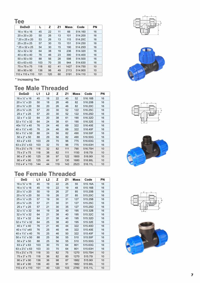
TeeDxDxD L Z Z1 Mass Code PN
16 x 16 x 16 45 22 11 66 514.160 1620 x 20 x 20 50 26 13 101 514.200 16
* 20 x 25 x 20 53 26 13 115 514.20C 1625 x 25 x 25 57 30 15 151 514.250 16
* 25 x 32 x 25 54 30 15 190 514.25D 1632 x 32 x 32 64 38 19 236 514.320 1640 x 40 x 40 76 46 23 390 514.400 1650 x 50 x 50 88 56 28 598 514.500 1663 x 63 x 63 103 70 35 944 514.630 1675 x 75 x 75 118 82 41 1427 514.750 1090 x 90 x 90 136 98 49 2113 514.900 10
110 x 110 x 110 151 120 60 3191 514.110 10
* Increasing Tee
Tee Male ThreadedDxGxD L1 L2 Z Z1 Mass Code PN
16 x ½” x 16 45 18 22 40 52 516.16B 1620 x ½” x 20 50 18 26 46 82 516.20B 1620 x ¾” x 20 50 20 26 46 82 516.20C 1625 x ¾” x 25 57 20 30 52 122 516.25C 1625 x 1” x 25 57 20 30 52 122 516.25D 1632 x 1” x 32 64 20 38 61 190 516.32D 16
32 x 1¼” x 32 64 24 38 61 190 516.32E 1640x 1¼” x 40 76 24 46 69 322 516.40E 1640 x 1½” x 40 76 24 46 69 322 516.40F 1650 x 1½” x 50 88 24 56 82 490 516.50F 1650 x 2” x 50 88 29 56 82 490 516.50G 1663 x 2” x 63 103 29 70 96 775 516.63G 16
63 x 2½” x 63 103 32 70 96 775 516.63H 1675 x 2½” x 75 118 32 82 111 790 516.75H 1075 x 3” x 75 118 38 82 111 1150 516.75I 1090 x 3” x 90 125 38 97 122 1800 516.90I 1090 x 4” x 90 125 44 97 130 1680 516.90L 10
110 x 4” x 110 144 44 119 143 2523 516.11L 10
Tee Female ThreadedDxG L1 L2 Z Z1 Mass Code PN
16 x ⅜” x 16 45 19 22 25 55 515.16A 1616 x ½” x 16 45 19 22 19 48 515.16B 1620 x ½” x 20 50 19 26 27 85 515.20B 1620 x ¾” x 20 50 19 26 27 85 515.20C 1625 x ½” x 25 57 19 30 31 127 515.25B 1625 x ¾” x 25 57 21 30 31 127 515.25C 1625 x 1” x 25 57 21 30 35 127 515.25D 1632 x ½” x 32 64 19 38 40 195 515.32B 1632 x ¾” x 32 64 21 38 40 195 515.32C 1632 x 1” x 32 64 21 38 40 195 515.32D 16
32 x 1¼” x 32 64 25 38 40 195 515.32E 1640 x 1” x 40 76 21 46 44 322 515.40D 16
40 x 1¼” x40 76 25 46 44 322 515.40E 1640 x 1½” x 40 76 25 46 50 322 515.40F 1650 x 1½” x 50 88 25 56 55 510 515.50F 1650 x 2” x 50 88 25 56 55 510 515.50G 1663 x 2” x 63 103 30 70 64 801 515.63G 16
63 x 2½” x 63 103 33 70 64 801 515.63H 1675 x 2½” x 75 118 33 82 75 1270 515.75H 1075 x 3” x 75 118 36 82 80 1270 515.75I 1090 x 3” x 90 136 36 98 87 1882 515.90I 1090 x 4” x 90 136 40 98 91 1882 515.90L 10
110 x 4” x 110 151 40 120 103 2780 515.11L 10

�
Reducing TeeDxD1xD L L1 Z Z1 Mass Code PN
25 x 20 x 25 51.5 47 30 14 132 523.25B 1632 x 25 x 32 57.5 51 32 19 207 523.32C 1640 x 32 x 40 83 75 40 17 340 523.40D 1650 x 40 x 50 100 90 44 23 580 523.50E 1663 x 50 x 63 95 85 66 33 950 523.63F 16
Plug D L Mass Code PN16 45 30 521.160 1620 50 50 521.200 1625 57 65 521.250 1632 64 100 521.320 1640 76 165 521.400 1650 88 245 521.500 1663 103 390 521.630 1675 118 655 521.750 1090 136 950 521.900 10110 151 1420 521.110 10
Flange AdaptorDxDN L D1 D2 n°Drill Mass Code PN
75 x 2½” 118 145 185 4 886 520.75H 1075 x 3” 118 160 200 8 992 520.75I 1090 x 3” 136 160 200 4 1198 520.90I 1090 x 4” 136 180 220 8 1364 520.90L 10110 x 4” 151 180 220 8 1684 520.11L 10

�
Installation16-63mm
Use a pipe cutter to cut pipe at 90° to its axis. Fig 1
Insert over the pipe end in the following order: nut, clinch ring and O-ring on the mouth of the pipe. Fig 2
Insert the pipe end and O-ring into the body of the joint; up to the insertion depth tab. Fig 3
Push the clinch ring into the body of the joint. Fig 4
Engage the nut and fully tighten. The nut can be tightened manually up to fittings of 32 mm diameter. It is advisable to use a strap or plumbing wrench for larger diameter fittings. Fig 5 & 6
•
•
•
•
•
Fig. 1
Fig. 2
Fig. �
Fig. �
Fig. �
Fig. �

10
75-90mmUse a pipe cutter to cut pipe at 90° to its axis.
Fig 1, pg 9Insert over the pipe end in the following order:
nut, clinch ring, thrust bushing and O-ring on the mouth of the pipe. Fig 7
Lubricate the pipe and the O-ring. Insert the pipe end and O-ring into the body of the joint; up to the insertion depth tab. Fig 8
Push the thrust bushing into the body of the joint. Slide the clinch ring up to the thrust bushing. Fig 9
Engage the nut and fully tighten with a strap or plumbing wrench. Fig 5 & 6, pg 9
•
•
•
•
•
Fig. �
Fig. �
Fig. �

11
110mmUse a pipe cutter to cut pipe at 90° to its axis.
Fig 1, pg 9Insert over the pipe end in the following order:
nut, thrust bushing and O-ring on the mouth of the pipe. Fig 10
Lubricate the pipe and the O-ring. Insert the pipe end and O-ring into the body of the joint; up to the insertion depth tab. Fig 11
Push the thrust bushing into the body of the joint and fasten the nut.
Unfasten the nut and slip the clinch ring over the pipe. Slide the clinch ring up to the thrust bushing. Fig 12
Engage the nut and fully tighten with a strap or plumbing wrench. Fig 5 & 6, pg 9
•
•
•
•
•
•
Fig. 12
Fig. 11
Fig. 10

BranchesJohannesburg | Bloemfontein | Durban | East London | George | Nelspruit
Polokwane | Port Elizabeth | Marley Export DivisionHead Office: 1 Bickley Road, Pretoriusstad, Nigel • P.O. Box 67, Nigel, 1490
www.marleypipesystems.co.za
Tel: 0861-MARLEY(0861-627539)