Marking Guide - NACHI Laboratories developed the Panelboard Marking Guide to help electrical...
24
Underwriters Laboratories Inc. ® Marking Guide Panelboards July 2004
-
Upload
doankhuong -
Category
Documents
-
view
220 -
download
1
Transcript of Marking Guide - NACHI Laboratories developed the Panelboard Marking Guide to help electrical...
1
UnderwritersLaboratories Inc.®
Marking Guide
PanelboardsJuly 2004
2
Panelboards are no longer a simple assembly of switches, fuses and circuit breakers for single ampere andvoltage systems. Today, there are panelboards for a variety of electrical supply systems with overcurrentprotections for many short-circuit capabilities. This has resulted in a complex marking system.
Underwriters Laboratories developed the Panelboard Marking Guide to help electrical inspectors determinethe meaning and reasons for today’s complex panelboard markings.
This booklet contains explanations of markings on panelboard nameplates, wiring diagrams and enclosuresfor panelboards used in ordinary locations, rated 600 volts or less.
The term “panelboard” used in this booklet also applies to modular panelboards unless otherwise noted.
The Table of Contents lists the main headings and their page numbers. The Index gives an alphabeticallist of specific items and the section numbers where information about them can be found.
This marking guide is not comprehensive; it covers those markings that have generated questions. Inspectorscan find additional information on marking requirements in the guide information for Panelboards(QEUY) and Modular Panelboards (QFOF) in the UL Electrical Construction Materials Directory.Complete information regarding the provision of markings and instructions for these panelboards iscontained in the Standard for Panelboards, UL 67 (eleventh edition, dated December 8, 1993).References to the National Electrical Code ® (NEC) are to the 2002 edition, with parenthetical referencesto the 1993 edition.
Let us know what you think about the Panelboard Marking Guide. Send your comments and suggestions to:Robert Osborne
Principal Engineer (PDE)Power Distribution EquipmentUnderwriters Laboratories Inc.
12 Laboratory DriveResearch Triangle Park, NC 27709
Copyright © 2004 Underwriters Laboratories Inc.®
3
CONTENTS
GENERAL INFORMATION ...................................................................................................................... 4
COMPANY IDENTIFICATION .................................................................................................................. 4
CATALOG DESIGNATION ....................................................................................................................... 4
ELECTRICAL RATING............................................................................................................................. 4
VOLTAGE RATING .................................................................................................................................. 5
CURRENT RATING ................................................................................................................................. 5
SHORT-CIRCUIT CURRENT RATINGS.................................................................................................. 6
SUITABLE FOR USE AS SERVICE EQUIPMENT .................................................................................. 7
CABINETS AND ENCLOSURES ............................................................................................................. 9
ENCLOSURE TYPES ............................................................................................................................ 10
PANELBOARDS WITH OVER 42 OVERCURRENT PROTECTIVE DEVICES ..................................... 11
COPPER OR ALUMINUM WIRING ........................................................................................................ 11
TEMPERATURE RATING OF INSTALLED CONDUCTORS.................................................................. 11
FIELD INSTALLED UNITS OR EQUIPMENT ........................................................................................ 12
MODULAR PANELBOARDS ................................................................................................................. 13
CLASS CTL PANELBOARDS ................................................................................................................ 13
IDENTIFICATION OF PHASE ARRANGEMENT AND THREE-PHASE, FOUR-WIRE DELTA SYSTEMS ...... 14
FACTORY BONDED NEUTRALS .......................................................................................................... 14
EQUIPMENT GROUNDING TERMINAL BAR ....................................................................................... 15
GROUND-FAULT PROTECTION OF EQUIPMENT .............................................................................. 15
MAXIMUM SIZE FUSEHOLDERS OR CIRCUIT BREAKERS .............................................................. 16
PANELBOARDS WITH PROVISIONS FOR WATT-HOUR METERS ................................................... 16
CIRCUIT BREAKER TRIP INDICATION ................................................................................................ 16
WIRING TERMINALS ............................................................................................................................ 17
MAIN OR MAIN DISCONNECT ............................................................................................................. 17
WIRE BENDING SPACE ....................................................................................................................... 18
ACCESSIBLE ONLY TO QUALIFIED PERSONS ................................................................................. 18
INDEX .................................................................................................................................................... 19

4
GENERAL INFORMATION
1. UL includes manufacturers of ordinary location panelboards under the category “Panelboards(QEUY)” and modular panelboards under the category “Modular Panelboards (QFOF)” in the ULElectrical Construction Materials Directory (Green Book) and online at www.ul.com/database.
The evidence of Listing is the Listing Mark on the product. The Listing Mark for panelboards includesthe name and/or symbol of Underwriters Laboratories Inc., together with the word “Listed,” a controlnumber, and one of the following product names as appropriate: “Panelboard,” “EnclosedPanelboard,” and “Marine, Enclosed Panelboard For Use on Vessels Over 65 Feet.” The productname may include the wording “Class CTL” or “Suitable For Use As Service Equipment” whereappropriate. The product name “Enclosed Panelboard” covers both the panel and enclosure withwhich it is provided.
The product names for modular panelboards are “Panelboard Module” and “Panelboard AccessoryModule.”
The basic Standard used to investigate products in these categories is the Standard for Panelboards,UL 67. In addition, each accessory module in a modular panelboard system is investigated inaccordance with the applicable UL Standard.
Panelboard markings may be molded, die-stamped, paint-stenciled, stamped, etched in metal thatis perma-nently secured, or printed on a label secured by adhesive and located so that it will not becovered when the units are installed. Some markings may be located on a wiring diagram in a pocketwithin the panelboard.
COMPANY IDENTIFICATION2. If there is a question on the design or construction of a panelboard, the identification of the
organization responsible for the product is important. This is one of the basic markings required bySection 110.21 (110–21) of the National Electrical Code® (NEC).
For manufacturers who produce panelboards at more than one factory, UL also requires a distinctivemarking to identify the factory at which the panelboard was made. This information is generallyfound on the UL Listing label. It enables the manufacturer to pinpoint problems and take immediateaction.
3. UL requires the manufacturer’s identification be visible without disturbing interior parts and factoryor field installed wiring. Whether the marking appears on an inside wall of the enclosure or on theside of a barrier, the manufacturer’s identification must be located near the front edge of the box orbarrier.
CATALOG DESIGNATION4. Panelboards are marked with a Cat. No., a general type designation or other distinctive marking
identifying the particular panelboard construction. Additional designations are provided on modularpanelboards.
ELECTRICAL RATING5. UL also requires that the basic electrical rating markings be visible without disturbing wiring or other
interior parts. Electrical rating information includes voltage and ampere ratings. For alternatingcurrent ratings, the information includes the number of phases, if other than single phase, and thefrequency, if other than 50 or 60 hertz.

5
VOLTAGE RATING6. The basic voltage rating markings must be visible without disturbing wiring and other interior parts.
A panelboard designed and intended for use only on a supply circuit involving two different potentials(for example, 120/240 volts, three-wire; or 208Y/120 volts, three-phase, four-wire) is so marked.
In many cases, however, the basic voltage rating marking — for example, 480 volts, three-phase— indicates that the panelboard is suitable for various supply systems (such as 208Y/120 volts,three-phase, four-wire; 120/240 volts, three-wire; 240/120 volts, three-phase, four-wire delta, etc.).These voltage ratings may be shown on a wiring diagram affixed to the panelboard or its enclosure.
7. A single-phase, three-wire panelboard is not permitted to be marked with a 120/240 volt, three-phase, four-wire delta rating. Three-wire panelboards should not be used for this system. The useof a delta breaker to adapt a three-wire panelboard to the system has been prohibited by Section408. 16(e) (384-16(e)) of the NEC,.
Although delta breakers could be used properly in three-wire, split-bus panelboards, they werebeing misused in three-wire panelboards with a single main disconnect.
Misusing delta breakers in this manner allowed voltage to backfeed through the delta breaker loadwhen the panelboard main disconnect was opened. This allowed voltage to be present on the mainbus bars when none was expected.
CURRENT RATING8. The current rating of a panelboard is the maximum continuous current that can be supplied through
the main terminals.
Main overcurrent protection devices, however, should not be loaded continuously to more than 80percent of their rating if opening of the overcurrent device is to be avoided. This is also true for branchovercurrent devices.
9. The current rating of a panelboard may be supplemented by one or more reduced ratings, eachapplicable under specified conditions.
For example, a manufacturer may wish to provide terminals suitable for both copper or aluminumwire but space in the panelboard may not be sufficient for terminals and wire bending space. In thiscase, the ampere rating is reduced to compensate for the size of aluminum wire that can be used.Sometimes there is a need for a lighting and appliance panelboard with a main circuit breaker to havea current rating less than the normally required rating of the panelboard. In this case, the markedcurrent rating is followed by the words “Maximum — See main circuit breaker rating.” This does notapply to panelboards having a main fused switch. Such panelboards are not provided with fuseswhen stocked. Lower rated fuses within the same case size, however, can be installed later.
10. A lighting and appliance panelboard marked as suitable for use as service equipment is limited totwo main disconnects. To prevent overloading, the current rating of such panelboards shall equalthe combined current ratings of the two disconnects as required by Section 408.16(A) (384–16(a))of the NEC. Where main disconnects are not provided with the panelboard, the NEC requires thatmain overcurrent protection be provided in the feeder circuit supplying the panelboard.
11. If the ampacities of the ungrounded (main) bus bars and the grounded (neutral) bus bars are notidentical, the current rating markings of the panelboard are required to show the ampacity of eachbus bar.
6
While it is unusual for the phase bars to be of different ampacities, the neutral can be a reduced sizeaccording to Section 220.22 (220–22) of the NEC. This is unusual for standard panelboard designs,as most have full neutral ampacity.
Because neutrals are often fabricated from connector bars with unusual shapes, in most cases itis not possible to judge ampacity from physical dimensions. UL conducts a temperature test on theassembly to determine ampacity.
12. If a panelboard employs a snap switch in any branch circuit, it cannot be rated more than 200amperes unless there is a supply side overcurrent protection at 200 amperes or less within thepanelboard. This requirement assumes that panelboards rated 200 amperes or less will be installedwith overcurrent protection in accordance with Section 408.16(c) (384–16(b)) of the NEC.
Section 408.16(c) (384–16(b)) of the NEC was adopted years ago when snap switch panelboardswere common and short circuit problems were caused by small electrical spacings between liveparts and the ground within snap switches. It should be noted that this Section does not apply to snapswitches rated over 30 amperes or to switches or circuit breakers that have larger electrical spacingsand are suitable for use as service disconnects.
SHORT-CIRCUIT CURRENT RATINGS13. A panelboard is required to be marked with the phrase “Short-Circuit-Current-Rating” and the rating
in rms symmetrical amperes. This phrase indicates that (1) that the overcurrent devices are capableof opening the circuit under fault conditions; and (2) the panelboard bus structure will withstand themagnetic forces generated by fault current passing through it. These markings are provided toensure proper installation with respect to Sections 110.9 (110-9) and 110.10 (110-10) of the NEC.
Also, switches and circuit breakers under switching operations must be capable of closing in on afault of the magnitude indicated. In addition, they must open satisfactorily on lesser faults of suchmagnitude that the opening of the overcurrent feature is delayed.
The letters rms stand for root-mean-square. This is the value that would be read on an ordinaryammeter. Symmetrical means that the marked current value on the panelboard is the steady-statevalue of the fault current the panelboard can handle.
14. Since the ability of an overcurrent protection device to open on fault currents is affected by thevoltage rating of the circuit, a panelboard may have several short-circuit current ratings, eachassociated with a specific voltage rating.
15. Panelboards that contain watt-hour meters other than those intended for use with currenttransformers are additionally marked with the phrase “Watt-hour meter not included in the short-circuit rating” since the meters are not evaluated during the performance of the short-circuit currenttest.
16. Many panelboards are designed to accept various types of circuit breakers or fused switches withdifferent high-interruption ratings. Some of these ratings may be less than the panelboard ratings.Panelboards are required to be marked to indicate that the short-circuit rating is limited to the lowestinterrupting capacity of any device installed in the panelboard.
Some panelboards may be marked to indicate one or more short-circuit ratings which are dependenton the use of specific integral or remote main overcurrent protective devices. An example of sucha marking is: “When protected by _____ ampere maximum Class _____ fuse or (Manufacturer’sname and type designation) circuit breaker rated not more than _____ amperes, this panelboardis suitable for use on a circuit capable of delivering not more than _____ rms symmetrical amperes,_____ volts maximum,” or an equivalent statement.

7
Some panelboards are marked for installation of circuit breakers having a lower short-circuit currentrating than the panelboard short-circuit rating. The circuit breakers are acceptable for use abovetheir marked short-circuit rating if used on the load side of a specific overcurrent device. In suchcases, the panelboard is marked as follows (the blank spaces would be filled with the appropriateinformation):
1. The short-circuit current rating of this panelboard is equal to the lowest short-circuit current ratingof any installed circuit breaker or fused switch, but not more than _____ rms symmetrical amperesat _____ volts, three-phase, or_____ rms symmetrical amperes at _____ volts, single-phase; and
2. The short-circuit current rating of a circuit breaker is 5,000 rms symmetrical amperes and for a fusedswitch is 10,000 rms symmetrical amperes, or as marked on the device, except for the followingseries combination ratings:
A load side circuit breaker may be a branch, sub-main, or an integral main used on the load sideof a remote main. A line side circuit breaker or fused switch may be a sub-main, integral main, ora remote main. This series combination short-circuit current rating shall not exceed that of the lineside circuit breaker or fused switch.
17. There are other markings that specify special conditions when a short-circuit current rating isapplicable. These markings must be followed whenever overcurrent devices are added or replaced.
SUITABLE FOR USE AS SERVICE EQUIPMENT18. These are the basic requirements that a panelboard rated 600 volts or less must meet in order to
be used as service equipment:
A. Service disconnecting means must be provided.
B. Each service disconnect provided must have a switching feature that disconnects all conductorsfrom the service-entrance conductors and that is suitable for use as a service disconnect. There isone exception: the neutral service conductor can be disconnected by removing the wires from thepressure wire connectors on the service neutral bus as noted in Section 230.75 (230–75) of the NEC.In general, snap, toggle or similar switches, are not acceptable because their internal electricalspacings are too small. The exception in Section 225.36 (230–84(b)) of the NEC for branch circuitswitches used to disconnect garages and out buildings on residential property does not apply to theservice disconnects in a panelboard.
Circuit breakers, either molded case, fused, or in combination with ground fault circuit interrupters,are suitable for use as service disconnects. Other devices that are used to protect individual circuits,circuits within equipment or appliances, or circuit protectors without on and off features, are notsuitable for use as service disconnects.
The removal of a plug or cartridge fuse from its fuseholder, while serving to de-energize the circuit,does not provide service disconnection. Panelboard switches, pullout switches and some industrialcontrol switches are suitable as service disconnects. Note that pullout switches, while they serve asa fuse puller, do have switchblades and contact jaws and are tested as switches.
Load Side Circuit BreakersMfr Type Poles Amp Rating
Line Side Circuit BreakersMfr Type Amp Rating
Interrupting RatingSymmet Amp rms Volts ac Phases
Load Side Circuit BreakersMfr Type Poles Amp Rating
Line Side Fused SwitchFuse Class Volts ac Amp
Interrupting RatingSymmet Amp rms Volts ac Phases

8
C. Overcurrent protection suitable as branch or feeder protection must be provided for serviceconductors. Miscellaneous, miniature and micro fuses, thermal cutouts, relays and othersupplementary overcurrent protection are not acceptable.
D. The number of service disconnects and overcurrent devices must conform to the NEC, Section230.71 (230–71).
E. As required in Section 230.95 (230-95) of the NEC, Panelboards rated for use on solidly groundedwye electrical services of more than 150 volts to ground must provide ground fault protection foreach service disconnect rated 1000 amperes, or more. An exception is covered under Item 53.
F. There must be provision for connecting a grounded service conductor and a grounding-electrodeconductor. If there is a neutral bus, a means to bond the panelboard enclosure or mounting pan tothe neutral bus is required unless the bus is mounted in electrical contact with the enclosure or pan.
19. In general, the grounding-electrode connection in service equipment is required to be made to thegrounded service conductor at the neutral bar. However, Section 250.24(A)(4) (250–23(a),Exception No. 5) of the NEC permits this connection to be made to the equipment grounding terminalbar, provided the main bonding jumper is a wire or a bus bar and is installed from the neutral barto the equipment grounding terminal bar. If in a panelboard suitable for use as service equipment,the main bonding jumper wire or bus bar is provided for field installation, instructions are markedon the panelboard for proper installation of the jumper.
20. A panelboard with the neutral insulated from the enclosure may be marked “Suitable for use asservice equipment when not more than six main disconnecting means are provided” when thefollowing conditions are met:
A. There must be at least one combination of switching units that can be mounted to occupy allavailable space for switching units; and, whether by using handle ties or similar devices, not morethan six main disconnects will result (including factory-installed disconnects).
*See Item 23 for lighting and appliance panelboards.
B. With this combination of switching units, no more than six overcurrent-protective devices will beconnected to each ungrounded service conductor.
Note that a panelboard marked “Suitable for use as service equipment when not more than six maindisconnecting means are provided” may permit some combinations of switching units varying inampere ratings and physical size that would exceed the six disconnect rule on a completely filledpanelboard. The six disconnect rule can be exceeded if handle-ties are not installed where needed.
Panelboards marked as noted above and used as service equipment must have the neutral bondedto the enclosure as required by Section 408.3(C) (384–3(c)) of the NEC. These panelboards areprovided with means to accomplish this bonding. When the panelboard is not used as serviceequipment, the neutral bonding means must not be installed. This would violate Section 250.24(A)(5)(250–61(b)) of the NEC and would constitute a fire hazard as noted in Item 50 of this Marking Guide.
21. A panelboard with the neutral factory-bonded to the enclosure is marked “Suitable only for use asservice equipment. Install no more than six main disconnecting means.”
22. Some panelboards may have the required number of handles and service overcurrent devices,when the maximum number of the smallest units are installed and used without handles or ties orsimilar devices. These panelboards may have the shorter marking “Suitable for use as serviceequipment” or “Suitable only for use as service equipment.” The shorter marking is suitable for Class

9
CTL (circuit limited) lighting and appliance panelboards since they cannot have more than two mainovercurrent protective devices as specified in Section 408.16(A) (384-16(a)) of the NEC.
23. Class CTL lighting and appliance panelboards without main overcurrent protection usually are notmarked suitable for service equipment use. Such panelboards, with not more than 10 percent of theirovercurrent devices rated 30 amperes or less, however, may be suitable for use as serviceequipment. They are marked “Suitable for use as service equipment when not more than six maindisconnecting means are provided and when not used as a lighting and appliance branch-circuitpanelboard; see Section 408.14 (384–14) of the NEC.”
24. A panelboard intended for service equipment use must have the marking “Service Disconnects”near the switch or circuit breaker handles. If this is not done in the factory, pressure sensitive labelsmust be provided. This marking identifies the service disconnects when branch disconnects are alsopresent. This is required by Section 230.70(B) (230–70) of the NEC.
CABINETS AND ENCLOSURES25. Panelboards are installed in cabinets, cutout boxes, or within compartments of other equipment,
such as deadfront switchboards. Some panelboards are shipped from the factory in an enclosuredesigned for their use. When they are, the manufacturer is permitted to place the UL Listing Mark“Enclosed Panelboard” with or without additional modifying phrases on the assembly or use a“Panelboard” Listing Mark with or without additional modifying phrases with an “Electric CabinetBox” Listing Mark and an “Electric Cabinet Front” Listing Mark.
26. Except for the panelboards intended for service equipment use discussed in Item 27, it is theresponsibility of the installer to match a panelboard with an enclosure that is suitable in size andconstruction. The enclosure must meet the requirements of the NEC including wiring space, wirebending space, and environmental conditions.
27. Because of the importance of grounding and bonding at service locations, UL requires that apanelboard marked as suitable for use as service equipment be identified with a particular box.Unless the panelboard cannot readily be removed from the box in which it is shipped from the factory,UL also requires that the panelboard marking identify the box or boxes with which it is intended tobe used.
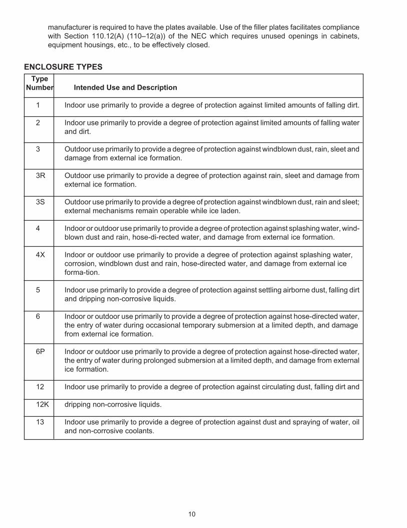
28. The suitability of an enclosure for environmental conditions for which it has been investigated isindicated by an enclosure type designation. One or more of the type designations indicated on thefollowing pages are marked inside or outside the panelboard enclosure.This marking helpsinspection authorities to judge whether an enclosure is suitable for a specific environment asmentioned in Section 110.3(A)(1) (110–3(a)(1)) of the NEC.
See page 7 for Enclosure Types.
An enclosed panelboard marked with an enclosure designation of Type 3, 3S, 4, 4X, 6 or 6P mayadditionally be marked “Raintight” or “Rainproof.” An enclosed panelboard marked with anenclosure designation of Type 3R may additionally be marked “Rainproof.”
Some enclosed panelboards have a semi-flush enclosure which has a flange extending from thesidewalls. This type of enclosure is intended to be mounted such that the front portion of theenclosure projects out of the wall and the rear portion extends within the wall in which it is mounted.These panelboards are marked with instructions regarding the proper overlap or flashing to beprovided in the installation.
29. For some panelboards, it is intended that unused openings in the enclosure be closed by filler plates.These panelboards are marked with the catalog number of the filler plates to be used, and the
10
manufacturer is required to have the plates available. Use of the filler plates facilitates compliancewith Section 110.12(A) (110–12(a)) of the NEC which requires unused openings in cabinets,equipment housings, etc., to be effectively closed.
ENCLOSURE TYPESType
Number Intended Use and Description
1 Indoor use primarily to provide a degree of protection against limited amounts of falling dirt.
2 Indoor use primarily to provide a degree of protection against limited amounts of falling waterand dirt.
3 Outdoor use primarily to provide a degree of protection against windblown dust, rain, sleet anddamage from external ice formation.
3R Outdoor use primarily to provide a degree of protection against rain, sleet and damage fromexternal ice formation.
3S Outdoor use primarily to provide a degree of protection against windblown dust, rain and sleet;external mechanisms remain operable while ice laden.
4 Indoor or outdoor use primarily to provide a degree of protection against splashing water, wind-blown dust and rain, hose-di-rected water, and damage from external ice formation.
4X Indoor or outdoor use primarily to provide a degree of protection against splashing water,corrosion, windblown dust and rain, hose-directed water, and damage from external iceforma-tion.
5 Indoor use primarily to provide a degree of protection against settling airborne dust, falling dirtand dripping non-corrosive liquids.
6 Indoor or outdoor use primarily to provide a degree of protection against hose-directed water,the entry of water during occasional temporary submersion at a limited depth, and damagefrom external ice formation.
6P Indoor or outdoor use primarily to provide a degree of protection against hose-directed water,the entry of water during prolonged submersion at a limited depth, and damage from externalice formation.
12 Indoor use primarily to provide a degree of protection against circulating dust, falling dirt and
12K dripping non-corrosive liquids.
13 Indoor use primarily to provide a degree of protection against dust and spraying of water, oiland non-corrosive coolants.

11
PANELBOARDS WITH OVER 42 OVERCURRENT PROTECTIVE DEVICES30. These are power or distribution panelboards — not lighting and appliance panelboards. More than
10 percent of the total number of the installed overcurrent devices (poles) cannot be rated 30amperes or less with neutral connections. See Section 408.14 (384–15) of the NEC. If such apanelboard leaves the factory with space that allows for the field installation of too many 30 ampereovercurrent devices, with neutral connections, the panelboard could end up unintentionally as alighting and appliance panelboard. In this case, the panelboard is required to be marked “Lightingor appliance branch circuits are not to be supplied directly through more than 10 percent of thebranch circuit overcurrent protective devices.”
This marking is required to be readily visible after the panelboard has been installed and is intendedto alert the installer and inspection authorities that the panelboard does not meet the requirementsfor lighting and appliance panelboards. This marking is not required, however, if the panelboard isalternately marked “Communication Circuit Panelboard—For Telephone Company Use Only.”
COPPER OR ALUMINUM WIRING31. Panelboards intended for use with aluminum wire require special consideration. First, panelboard
wire connectors must be recognized for use with aluminum wire. Second, the size of the enclosuremust be increased because aluminum wire is larger than copper wire of the same ampacity. Thisrequires more cross sectional area for the wiring gutters and more wire bending space at terminalsand where wires enter the enclosure. Third, the larger wiring terminals may make it necessary tocheck through-air electrical spacings between adjacent terminals of opposite polarity.
32. Because of these considerations, UL requires the wiring diagram or nameplate to be marked toindicate the use of copper and/or aluminum wire if the symbol “AL” appears on any part that isintended for use in the panelboard. It may be necessary to remove a cover, front or trim to see themarking.
33. If the panelboard is not acceptable for use with aluminum wire, the marking will read “Use CopperWire Only.”
34. If the wiring terminals and other factors are acceptable for use with copper and aluminum wire, thepanelboard is required to be marked “Use Copper or Aluminum Wire.”
35. If only some terminals are acceptable for use with aluminum and copper wire with the remainderacceptable for use with copper wire only, the panelboard is required to be marked “Use copper wireonly, except at terminals...” Variations of this marking are also permitted if the terminals that areacceptable for use with aluminum wire are identified.
TEMPERATURE RATING OF INSTALLED CONDUCTORS36. In general, the testing and construction of panelboards are based on the use of 60°C ampacities
for wire size Nos. 14–1 AWG and 75°C ampacities for wire size Nos. 1/0 AWG and larger, takenfrom Table 310.16 (Table 310–16) of the NEC. The panelboards are marked to indicate temperatureratings and sizes of conductors that can be used.
If the equipment is normally intended for wire sizes within the range 14–1 AWG but is marked 75°Conly or 60/ 75°C, it means that the 75°C wire may be used at full 75°C ampacity.
Higher temperature rated conductors than specified may be used if the size is based on thepreceding statements. When the connection is made to a circuit breaker or switch unit within theequipment, such a unit also must be marked for the temperature rating of the conductor.

12
37. Panelboards suitable for use as service equipment with the appropriate main terminal provisionscan be used with reduced wire sizes indicated in Section 310.15(B)(6) and Table 310.15(B)(6) (Note3 of Table 310–16) of the NEC if the wire connectors are also suitable for the reduced wire size.
A panelboard not having facilities for the normal size wire may still have an ampere rating that isbased solely on use in accordance with this requirement. In this case, the panelboard must bemarked to indicate that the rating is applicable only if the panelboard is installed as single-phase,three-wire residential service equipment. For example, a panelboard rated “200 ampere maximum—see main circuit rating” could be designed for an enclosure that provides 6 inches of wire bendingspace suitable for 2/0 AWG in accordance with Table 312.6(B) (Table 373– 6(b)) of the NEC. Thepanelboard would then have to be marked to indicate that the 200 ampere rating applies only if thepanelboard is installed as single-phase, three-wire residential service equipment. With a 175ampere or smaller main breaker installed, the panelboard could be installed elsewhere sincebending space would be adequate for the wire sizes required by Table 310–16.
FIELD INSTALLED UNITS OR EQUIPMENT38. A panelboard to which a unit, such as a circuit breaker, switch, or the like, may be added in the field
is required to be marked to identify the units that can be added. Units made by differentmanufacturers or of a different style are not identical in all details and therefore may not beinterchangeable.
Plug-in clips and blades must be matched if poor connections and overheating are to be avoided.Additionally, over-surface and through-air electrical spacings, between live parts of opposite polarityand to grounded metal, often depend on the proper mating of units and the bases into which theyare plugged or bolted.
39. Panelboards are usually provided with the required main line and neutral terminals. The overcurrentprotection units are furnished with required load terminals. However, if the pressure wire connectorsare not provided on the panelboard when shipped, the panelboard is required to be marked statingwhich pressure wire connectors or component terminal kits are acceptable for use with thepanelboard.
A main terminal kit consisting of individual wire connectors or an assembly of terminals, busconnectors and means for bolting or plugging, is required to be marked with the manufacturer’sidentification and catalog designation. If this is not done, the carton is required to be marked.Aseparate feed-through terminal kit requires similar marking and, if a separate enclosure is requiredfor its use, this too must be marked and provided with instructions for its use.
40. If a panelboard is intended to be used in a certain box or boxes and neutral terminals are mountedin that box, both the panelboard and the box are required to be marked. These markings mustindicate that each shall be used with the other unless the panelboard and box are shipped togetherfrom the factory. Some column type panelboards have the neutrals mounted in a separately listedjunction box. In this case, a tie-in marking is required.
41. Some panelboards have multiple voltage ratings, some of which require the use of a neutral whileothers do not. In this case, the neutral is not required to be mounted in place at the factory. Markingon the neutral assembly and panelboard, however, is required to tie the two together and provideinstructions for installing the neutral.
42. A panelboard that has space for the installation of additional branch circuit switches, circuit breakersor fuseholders may be shipped from the factory without the necessary branch-circuit bus bars. Inthis case, the panelboard must be marked to indicate the catalog number or the equivalent of thebus bar kit that is to be used when the unit is installed.

13
A panelboard supplied with branch-circuit bus bars for adding a branch-circuit unit is required to bemarked on a wiring diagram, on the branch-circuit bus bar or in some other location. This markingindicates the ampacity of the bus bar, unless its ampacity equals or is greater than the maximumcurrent rating of any unit to be connected to the panelboard.
A. Markings on panelboards that employ plug-on units require the use of a hold-down kit when the unitsare back-fed and the field installed supply conductors are terminated on the plug-on unit. Themarking indicates: “Back-fed _____ requires hold-down kit Cat. No._____ “ or the equivalent. Anidentification of the applicable back-fed unit is specified in the first blank-for example, circuit breaker,fused switch, or terminal kit; and the catalog number of the required hold-down kit is specified in thesecond blank.
MODULAR PANELBOARDS43. A modular panelboard system includes the following types of modules: an enclosed panelboard or
a column- type panelboard, and one or more accessory modules such as termination boxes,enclosed switches and circuit breaker enclosures. Each module of the system has one or moreopenings in one or more sides of the enclosure for bus bar connections, or terminals for field wiringconnections to other related modules. Typical applications for these modular systems includeapartment houses and strip malls. Panelboard modules used in these modular panelboard systemsare labeled “Panelboard Module” and all other system modules are labeled “Panelboard AccessoryModule.”
A panelboard module to which another panelboard accessory module — such as a termination box,enclosed switch, circuit breaker enclosure or the like — may be added in the field is required to bemarked to identify the panelboard accessory modules that can be added unless the entire modularpanelboard system is marked with a common series designation. In this case, the series designationis marked on the panelboard module and each panelboard accessory module.
CLASS CTL PANELBOARDS44. Section 408.14 (384–14) of the NEC defines a lighting and appliance panelboard as a panelboard
having more than 10 percent of its overcurrent devices rated 30 amperes or less, for which neutralconnections are provided. Once a panelboard is classified as a lighting and appliance branch-circuitpanelboard, certain limitations are placed on the number of overcurrent devices that may beinstalled.
Section 408.15 (384–15) of the NEC states that physical means shall be provided to prevent theinstallation of more overcurrent devices than the number for which the panelboard was designed,rated and approved. In no case shall the number exceed 42 (other than those provided for in themains) in any one cabinet or cutout box. This has the effect of limiting the number of circuits in alighting and appliance branch-circuit panelboard.
Using this concept, UL adopted the term “Class CTL” (a contraction of “Circuit Limiting”) to helpelectrical inspectors approve installations of lighting and appliance panelboards. All panelboardsthat must be classified as lighting and appliance branch-circuit panelboards are required to bemarked “Class CTL Panelboard” before they leave the factory.
45. Some power panelboards that have more than 42 branch- circuit overcurrent protective devices andneutral terminals have space for field installation of extra units. This could mean more than 10percent of the overcurrent devices will be rated 30 amperes or less when the panelboard iscompletely filled. In order to prevent such misapplications, specific markings are required onpanelboards of this design. See Item 30 for details.

14
46. If more than one size unit is intended for use in the panelboard (such as a full-size and half-size circuitbreaker), the smaller unit is required to be marked “Class CTL” or “CTL.” The larger may also beso marked.
Since space is limited on these units, the marking may not be visible after the unit is installed. TheCTL Unit marking is of significance only in those areas where the older style non-CTL, half-size, twin,and similar units are still available to the installer.
IDENTIFICATION OF PHASE ARRANGEMENT AND THREE-PHASE, FOUR-WIRE DELTA SYSTEMS47. Section408.3(E) (384-3(f))of the NEC specifies the required phase arrangement for 3-phase buses.
This Section also notes that the B-phase shall be that having the higher voltage to ground on a fourwire delta system. This Section also allows other busbar arrangements for additions to existinginstallations so long as the arrangement is marked. Section 110.15 (384-3(e)) of the NEC requiresmarkings to identify the B-phase as the higher voltage to ground on a four- wire delta connectedsystem when the midpoint of one phase is grounded.
Accordingly, UL requires that panelboards with other than an A-B-C bus bar arrangement be markedto indicate the bus bar arrangement. Also, UL requires that panelboards intended for a 240/120 volt,three-phase, four- wire, delta system be marked to identify the different bus bars with reference tothe voltage between them. However, if a panelboard is intended for use only on this system, the mainbus bar having the higher voltage to ground may be identified by an orange marking or by tagging.Such a panelboard must be marked to indicate the necessary voltage rating of the device for eachbranch-circuit position.
B-phase is 208 volts to ground while the A- and C-phases are only 120 volts to ground. Some circuitbreakers, like single-pole breakers for use with handle ties rated 120-240 volts, should not beconnected to the phase that is 208 volts to ground. Also, fuse holders for plug fuses should not beconnected where the voltage to ground exceeds 150 volts.
Generally, the B-phase is used only in conjunction with either the A- or C-phase for a 240 volt single-phase branch circuit or with both the A- and C-phase for a three-phase branch circuit. Circuitbreakers or cartridge fuses rated for straight 240 volt systems are suitable for this use.
48. The NEC requirements in Section 408.3(E) (384–3(f)) do not cover three-phase panelboards havingtwo buses and a neutral and intended for use on a 240 volt, three-phase, three-wire grounded B-phase system. In these panelboards, the neutral is connected to the grounded B-phase and mayhave various locations in the panelboard. UL requires that the two other buses have an A-, C-phasearrangement.
FACTORY BONDED NEUTRALS49. Some panelboards are intended only for service equipment use on an AC system requiring
grounding of the system (see Items 18-21 under “Suitable for Use as Service Equipment”). Thesepanelboards may have the enclosure bonded to the neutral at the factory. This eliminates the needfor a neutral insulating support base.
It is difficult to check for unintentional grounds on the installed building wiring when the neutral ismounted directly on the enclosure. Therefore, some manufacturers provide an insulating liner underthe neutral to permit use of a megger or similar resistance measurement instrument. However, thisdoes not provide the electrical spacings required for the neutral if the panelboard is used away fromthe service as a feeder or branch-circuit panelboard. These panelboards are required to be marked“Bonded Neutral — Remove bonding device for test purposes only” or an equivalent marking.

15
50. Most installers recognize the importance of bonding the neutral to the enclosure at the service. Manydo not realize, however, that it is just as important to omit the bonding and provide a fully insulatedneutral when the panelboard is used away from the service.
If neutrals are bonded at distribution points, the neutral currents take parallel paths through neutralfeeder conductors and metal raceways. If neutral feed conductors are open, the full neutral currentflows over the grounded raceway or the grounding conductor system. When this happens, the steelraceway joints and box connections overheat. This is a fire hazard.
EQUIPMENT GROUNDING TERMINAL BAR51. Section 408.20 (384–27) of the NEC requires the installation and use of a terminal bar for
panelboards used with non-metallic raceway or cable, or where separate grounding conductors areprovided. This terminal bar may be installed on the panelboard or its enclosure. A terminal barassembly kit must include instructions for installation and panelboard or enclosure markings.
Unless it employs a wire-binding screw, markings must show all acceptable wire sizes and wirecombinations for each terminal. A panelboard for use without grounding conductors is not requiredto provide for a grounding terminal bar. In this case, however, the panelboard must be marked tolimit its use to installations having equipment grounded by connection to metal raceway or metalliccable sheaths.
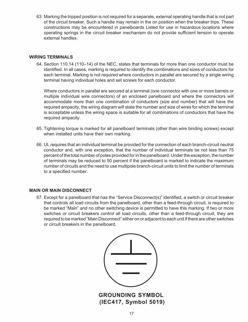
52. The equipment grounding terminal or assembly in a panelboard is identified by one of the followingmethods:
• The terminal assembly or the heads of the terminal screws being green;
• Marking adjacent to the terminal or on the wiring diagram indicating “Equipment-GroundingTerminal” or equivalent wording; or
• Marking of the grounding symbol (see below) adjacent to the terminal or on the wiring diagramalong with “Equipment-Grounding Terminal” or other words defining the symbol. The symbolmay be used without the additional wording if markings provided with the Panelboard define thesymbol.
GROUND-FAULT PROTECTION OF EQUIPMENT53. In accordance with Section 230.95 (230–95) of the NEC, a panelboard marked for use as service
equipment for three--phase, four-wire solidly grounded wye-connected services rated in excess of150 volts to ground but not exceeding 600 volts phase-to-phase shall be provided with ground-faultprotection for each service disconnect-ing means rated 1000 amperes or more.
Exception No.1 for Section 230.95 (230–95) of the NEC indicates that this does not apply to servicedisconnects for a continuous industrial process, where a non-orderly shutdown introduces additionalor increased fire and shock hazards.
In accordance with this Exception, UL permits a Listed panelboard marked for service equipmentuse and rated for use on solidly grounded wye electrical services of more than 150 volts to groundto omit ground-fault protection if the panelboard is marked “Suitable For Use As Service EquipmentOnly When Supplying A Continuous Industrial Process.” This shortened wording is not intended tocircumvent the need for a judgment. Inspectors concerned about the hazards of a non-orderlyshutdown decide whether or not ground-fault protection is needed.

16
54. In some panelboards, only a shunt trip service disconnect is provided. In this case, the marking onthe panelboards gives the manufacturer’s name and the catalog number of the ground-faultprotection equipment with instructions covering its interconnections.
55. Panelboards provided with ground-fault protection are required to be marked to indicate the circuit-main, feeder, or branch-circuit that is so protected. If a marking on the ground- fault sensing orrelaying equipment is not visible from the front of the panelboard with its cover removed, a separatemarking, such as on the wiring diagram, is required.
56. If a transformer providing control voltage for ground-fault protection is connected to the line side ofthe main disconnect, this disconnect may be identified as the “main.” In this case, the panelboardis required to be marked “Danger — this main does not disconnect control and instrument circuits”adjacent to the main disconnect.
57. In a panelboard with ground-fault protection, the part of the neutral bus used for load terminationsis required to be marked “WARNING — Do not connect grounding conductors to these or any otherneutral terminals, to do so will defeat ground-fault protection.” This marking must be placed on oradjacent to the neutral.
MAXIMUM SIZE FUSEHOLDERS OR CIRCUIT BREAKERS58. If the ampacity of a branch bus bar or wire is less than the maximum current rating of any fuse
accommodated by a fuseholder it supplies, or if it is less than the current rating of any trip unit ofan interchangeable trip circuit breaker that it supplies, UL requires a clear and permanent marking,plainly visible when the fuse or trip unit is being replaced. This prevents the use of a fuse or trip unithaving more ampacity than a bus bar or wire.
59. A panelboard with branch-circuit bus bars that permit adding a branch-circuit unit, circuit breaker,switch, or fuseholder requires markings on the wiring diagram, the branch-circuit bus bars, or someother location. Markings indicate the ampacity of the bus. Exception: if the ampacity of the bus baris not less than a) the maximum current rating of any unit to be connected to it; or b) the current ratingof the panelboard.
PANELBOARDS WITH PROVISIONS FOR WATT-HOUR METERS60. Separate meter sockets are required to be marked with a continuous ampere rating. In some cases,
meter sockets also may have a maximum use (intermittent) ampere rating of not more than 125percent of the continuous ampere rating. Similar markings are required for any meter mounting basein a panelboard. The continuous ampere rating may be less than the circuit that contains the metermounting base. This means that, for example, a 125 ampere panelboard can have a meter mountingbase rated “125 Amps (100 Amps Continuous).” Some inspectors may judge that a continuous dutymeter socket is not needed because of a panelboard’s load diversity. Continuous duty sockets canbe required when load and environmental conditions would cause overheating in panelboards.
61. If the socket jaws of meter mounting bases are mounted on terminals intended for field wiring, thepanelboard is required to be marked to indicate the maximum torque to be applied to theseterminals. This is given in the rotation prevention test for socket jaws and wire connectors in the ULrequirements for meter sockets.
CIRCUIT BREAKER TRIP INDICATION62. If the handle of a circuit breaker, or a simple extension of that handle, assumes other than the off
position when the breaker trips, the trip position of the handle is required to be indicated. The methodfor resetting the breaker is also a required panelboard marking.
17
63. Marking the tripped position is not required for a separate, external operating handle that is not partof the circuit breaker. Such a handle may remain in the on position when the breaker trips. Theseconstructions may be encountered in panelboards Listed for use in hazardous locations whereoperating springs in the circuit breaker mechanism do not provide sufficient tension to operateexternal handles.
WIRING TERMINALS64. Section 110.14 (110–14) of the NEC, states that terminals for more than one conductor must be
identified. In all cases, marking is required to identify the combinations and sizes of conductors foreach terminal. Marking is not required where conductors in parallel are secured by a single wiringterminal having individual holes and set screws for each conductor.
Where conductors in parallel are secured at a terminal (one connector with one or more barrels ormultiple individual wire connectors) of an enclosed panelboard and where the connectors willaccommodate more than one combination of conductors (size and number) that will have therequired ampacity, the wiring diagram will state the number and size of wires for which the terminalis acceptable unless the wiring space is suitable for all combinations of conductors that have therequired ampacity.
65. Tightening torque is marked for all panelboard terminals (other than wire binding screws) exceptwhen installed units have their own marking.
66. UL requires that an individual terminal be provided for the connection of each branch-circuit neutralconductor and, with one exception, that the number of individual terminals be not less than 75percent of the total number of poles provided for in the panelboard. Under the exception, the numberof terminals may be reduced to 50 percent if the panelboard is marked to indicate the maximumnumber of circuits and the need to use multipole branch-circuit units to limit the number of terminalsto a specified number.
MAIN OR MAIN DISCONNECT67. Except for a panelboard that has the “Service Disconnect(s)” identified, a switch or circuit breaker
that controls all load circuits from the panelboard, other than a feed-through circuit, is required tobe marked “Main” and no other switching device is permitted to have this marking. If two or moreswitches or circuit breakers control all load circuits, other than a feed-through circuit, they arerequired to be marked “Main Disconnect” either on or adjacent to each unit if there are other switchesor circuit breakers in the panelboard.
GROUNDING SYMBOL (IEC417, Symbol 5019)

18
WIRE BENDING SPACE68. A panelboard constructed in accordance with Exception No. 3 of Section 408.35 (384–25) of the
NEC is required to be marked by means of a diagram that shows and specifies the method of wiringthat shall be used to accomplish the 90-degree bend.
ACCESSIBLE ONLY TO QUALIFIED PERSONS69. Section 240.40 (240–40) of the NEC requires a disconnecting means on the supply side of cartridge
fuses where the fuses are accessible to other than qualified persons. Section 408.18 (384–18)requires all panelboards to be deadfront unless they are accessible only to qualified persons. ULrequires such panelboards to be marked “This panelboard shall be located where accessible onlyto qualified persons.”

19
INDEX
Item No.
Accessible Only to QualifiedPersons ................................................................................................... 69
Accessory Module ................................................................................................................................ 43
Aluminum Wire ................................................................................................................ 8, 31-32, 34-35
Ampacity—Bus Bar .............................................................................................................................. 11
Amperes per Pole ................................................................................................................................ 10
Ampere Rating ........................................................................................................... 7–11, 8–12, 36, 37
B-Phase .......................................................................................................................................... 47-48
Bonded Neutral ............................................................................................................................... 49-50
Bonding ............................................................................................................................... 11, 42, 47-48
Bus Bars ......................................................................................................................................... 58-59
Cabinets (Enclosures)..................................................................................................................... 25-28
Catalog Designations ....................................................................................................................... 4, 43
Circuit Breakers .............................................................................................................................. 25-28
Column Type Panelboards .................................................................................................................. 40
Communications Circuit Panelboard ............................................................................................. 30, 45
Company Identification (Factory Identification) ..................................................................................... 2
Conductors in Parallel .......................................................................................................................... 64
Continuous Rating-Meter Sockets .................................................................................................. 60-61
Copper or Aluminum Wiring ........................................................................................................... 31-35
CTL Panelboards ..................................................................................................... 10, 12, 22-23, 44-46
Current Rating............................................................................................................................ 8–12, 37
Delta Breakers ....................................................................................................................................... 7
Delta Systems .............................................................................................................................. 6–7, 47
Disconnecting Means........................................................................................................................... 18
Electric Cabinet Box or Front ............................................................................................................... 25
Electrical Rating ............................................................................................................................... 5–17

20
Enclosures (Cabinets)..................................................................................................................... 25-29
Equipment Grounding Terminal Bar .................................................................................................... 51
Factory Bonded Neutrals ................................................................................................................ 49-50
Factory Identification (Company ............................................................................................................ 2
Feed-Through Terminal Kits ................................................................................................................ 39
Field Installed Conductors .............................................................................................................. 36-37
Field Installed Units................................................................................................................... 17, 38-42
Filler Plates, Enclosure ........................................................................................................................ 29
Frequency, Alternating Current ............................................................................................................. 5
Fuseholder, Maximum Size ............................................................................................................ 58-59
Ground-Fault Protection ........................................................................................................... 18, 53-57
Grounded B-Phase .............................................................................................................................. 48
Grounded Service Conductor ........................................................................................................ 18, 21
Grounding ............................................................................................................................................ 27
Grounding Electrode Conductor ............................................................................................... 18-19, 64
Grounding Terminal Bar, Equipment .............................................................................................. 51-52
Half-Size Circuit Breakers .................................................................................................................... 46
Handle Ties .................................................................................................................................... 20, 47
Hold–Down Kits ................................................................................................................................. 42A
Identification of OrganizationResponsible for Product .......................................................................... 2
Loading, Continuous or Non-continuous ............................................................................................... 8
Location of Marking ........................................................................................................................... 1, 3
Lighting and Appliance Panelboards ....................................................................... 10, 12, 22-23, 44-46
Main Circuit Breaker ........................................................................................................................ 9, 67
Main Disconnects ..................................................................................................................... 10, 20, 67
Main Fused Switch ........................................................................................................................... 9, 67
Main Terminals .................................................................................................................................... 37
Material Used for Marking 1 Maximum Size, Fuseholder orCircuit Breaker .................................. 58-59
Meters—Watt-Hour ......................................................................................................................... 60-61

21
Modular Panelboards ....................................................................................................................... 1, 43
Multiple Voltage Ratings ........................................................................................................................ 6
NEC, Section
Definitions ............................................................................................................................................ 28
110.3(A)(1) ................................................................................................................................. 28
110.9 .......................................................................................................................................... 13
110.10 ........................................................................................................................................ 13
110.12(A) ................................................................................................................................... 29
110.14 ........................................................................................................................................ 64
110.21 .......................................................................................................................................... 2
220.22 ........................................................................................................................................ 11
230.70(B) ................................................................................................................................... 24
230.71 ........................................................................................................................................ 18
230.75 ........................................................................................................................................ 18
225.36 ........................................................................................................................................ 18
230.95 ............................................................................................................................. 18, 53-57
240.40 ........................................................................................................................................ 69
250.24(A)(4) ............................................................................................................................... 19
250.24(A)(5) ............................................................................................................................... 20
310.16 Table ......................................................................................................................... 36-37
310.15(B)(6) Table ..................................................................................................................... 37
312.6(B) ..................................................................................................................................... 37
384.3(F) ...................................................................................................................................... 47
408.3(C) ..................................................................................................................................... 20
408.3(E) ................................................................................................................................ 47-48
408.14 .................................................................................................................................. 23, 44
408.15 .................................................................................................................................. 30, 44
408.16(A) ............................................................................................................................. 10, 22
408.16(B) ................................................................................................................................... 12

22
408.16(E) ..................................................................................................................................... 7
408.18 ........................................................................................................................................ 69
408.35 ........................................................................................................................................ 68
408.20 ........................................................................................................................................ 51
Neutrals ........................................................................................................ 11, 20-21, 40-41, 49-50, 66
Neutral Disconnecting Means .............................................................................................................. 18
Number of Overcurrent ProtectiveDevices .......................................................................................... 10
Number of Phases, Alternating Current ................................................................................................ 5
Orange Marking ................................................................................................................................... 47
Organization Responsible for Product ................................................................................................... 2
Over 42 Overcurrent Devices .............................................................................................................. 30
Overcurrent Protection .................................................................................................................... 18-20
Phase Arrangement ........................................................................................................................ 47-48
Power Panelboards ........................................................................................................................ 30, 45
Pullout Switches ................................................................................................................................... 18
Rainproof—Raintight ........................................................................................................................... 28
Reduced Current Ratings ...................................................................................................................... 9
Residential Service Equipment ............................................................................................................ 37
Series Combination.............................................................................................................................. 16
Service Disconnects ...................................................................................................................... 18, 24
Service Equipment Use ............................................................................................................ 18-24, 37
Short-Circuit Current Rating .......................................................................................................... 13–17
Snap Switches ............................................................................................................................... 12, 18
Suitable for Use as Service Equipment .......................................................................................... 18-24
Suitable Only for Use as ServiceEquipment ........................................................................................ 21
Switches ................................................................................................................................... 12, 15, 17
Symmetrical Amperes .......................................................................................................................... 13
Tap Circuit ............................................................................................................................................ 64
Telephone Company Panelboard .................................................................................................. 30, 45

23
Temperature Rating of Installed Conductors .................................................................................. 36-37
Terminals .............................................................................................................................. 9, 39, 64-66
Terminal Kits ........................................................................................................................................ 39
Torque............................................................................................................................................. 61,65
Trademarks ............................................................................................................................................ 2
Trip Indication—Circuit Breakers .................................................................................................... 62-63
Type Numbers—Environmental ........................................................................................................... 28
Visibility ............................................................................................................................................... 3-6
Voltage Rating .............................................................................................................................. 6-7, 41
Watt-Hour Meters ......................................................................................................................... 60-61A
Wire Bending Space .................................................................................................................. 9, 31, 68
Wiring Space ................................................................................................................................... 9, 31
Wiring Terminals ................................................................................................................... 9, 39, 64-66

24
333 Pfingsten Road Northbrook, IL 60062(847) 272–8800Fax: (847) 272–8129
1655 Scott BoulevardSanta Clara, CA 95050(408) 985–2400Fax: (408) 296–3256
1285 Walt Whitman Road Melville, NY 11747(631) 271-6200Fax: (631) 271–8259
12 Laboratory DriveResearch Triangle Park, NC 27709 (919) 549–1400Fax: (919) 547–6000
2600 N.W. Lake RoadCamas, WA 98607(360) 817–5500Fax: (360) 817–6000