Marketing v. Reality in Multi- Antenna Wi-Fi
28
Marketing v. Reality in Multi- Antenna Wi-Fi Guide to Beamforming March 2011 Scott Reeves Technical Director EMEA
Transcript of Marketing v. Reality in Multi- Antenna Wi-Fi
Marketing v. Reality in Multi-Antenna Wi-Fi
Guide to Beamforming March 2011
Scott Reeves
Technical Director EMEA

2
Summary
Wi-Fi vendors are marketing chip-based beamforming more heavily
They gloss over limitations, naturally
Mutually-exclusive chip-based beamforming and spatial multiplexing
Zero gain from implicit beamforming, minimal (2 dB) from explicit
Zero client support today for explicit
Customers are easily confused, since all beamforming sounds the same to any non-specialist
A back-to-the-basics view (focusing on simple but technically accurate descriptions how multi-antenna techniques really work) can cut through the confusion
...and illustrate why Ruckus BeamFlex remains the superior approach

3
Conventional Wi-Fi: omni Tx pattern
4
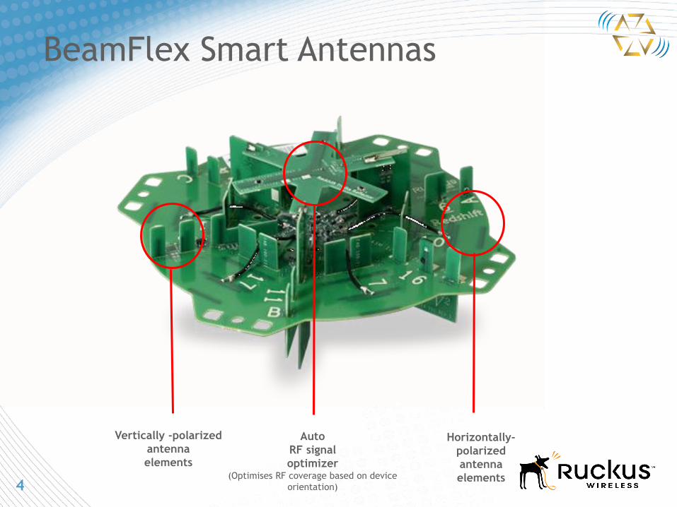
BeamFlex Smart Antennas
Auto
RF signal
optimizer (Optimises RF coverage based on device
orientation)
Horizontally-
polarized
antenna
elements
Vertically -polarized
antenna
elements

5
Automatic Interference Mitigation (AIM)
Chip-based beamforming has no mechanism to reject interference
Omni-directional antennas can’t ignore interference
BeamFlex mitigates interference by positioning antenna nulls in specific directions
Negating interference can be more beneficial than signal gain
5
Interference Rejection is Essential
-10db
interference
rejection
7 dBi signal gain

6
Key concepts: combination and phase
7
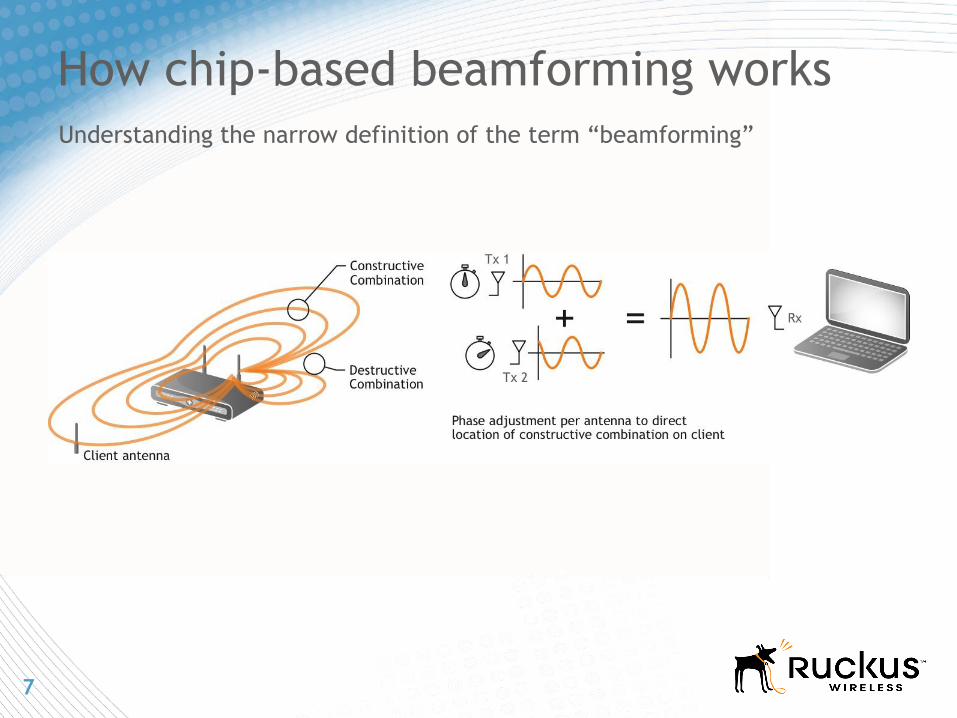
How chip-based beamforming works
Understanding the narrow definition of the term “beamforming”
8
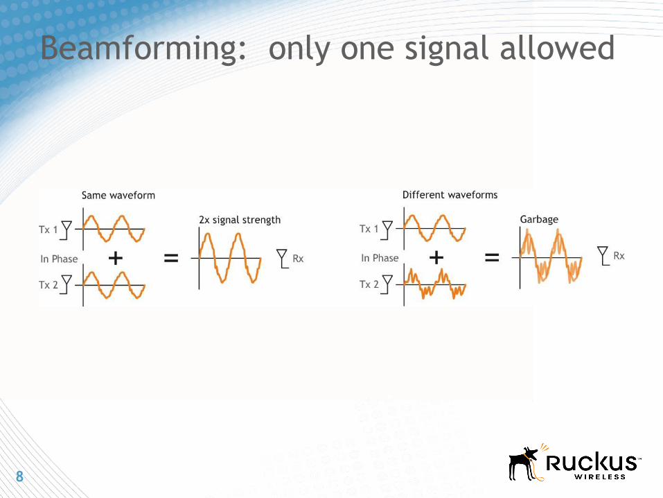
Beamforming: only one signal allowed

9
Chip Based Beamforming Limitations
Generates unwanted
interference and
wastes energy
No way to cope with
real-time interference
at the client
Beams predicated on
antenna separation
Optimal beamforming (5GHz) calls
for .5” antenna separation
Optimal spatial multiplexing
“requires” antenna separation at
inches (5GHz)
!
Client
Client
10
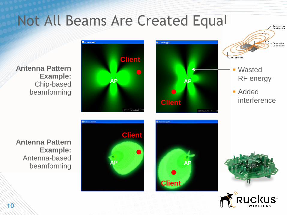
Not All Beams Are Created Equal
Client
Client
Client
Client
AP AP
AP AP
Antenna Pattern Example:
Chip-based beamforming
Antenna Pattern Example:
Antenna-based beamforming
Wasted
RF energy
Added
interference
11
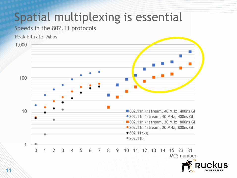
Spatial multiplexing is essential Speeds in the 802.11 protocols
1
10
100
1,000
0 1 2 3 4 5 6 7 8 9 10 11 12 13 14 15 23 31
802.11n >1stream, 40 MHz, 400ns GI
802.11n 1stream, 40 MHz, 400ns GI
802.11n >1stream, 20 MHz, 800ns GI
802.11n 1stream, 20 MHz, 800ns GI
802.11a/g
802.11b
Peak bit rate, Mbps
MCS number

12
How spatial multiplexing works

13
Why 3 radio chains don’t help
14
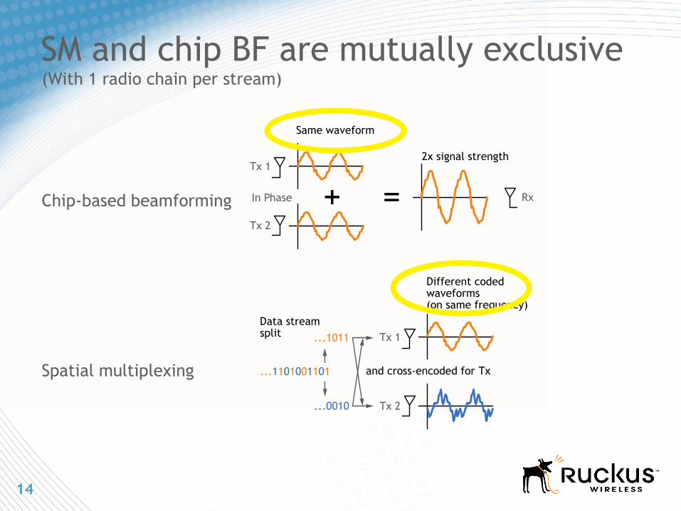
Tx 1
In Phase
Tx 2
2x signal strength
Same waveform
Rx
Tx 1
Tx 2
Different coded waveforms (on same frequency)
Data stream split
and cross-encoded for Tx
...0010
...1011
...1101001101
SM and chip BF are mutually exclusive
Chip-based beamforming
Spatial multiplexing
(With 1 radio chain per stream)
15
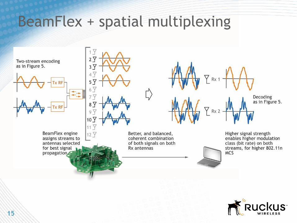
BeamFlex + spatial multiplexing
16
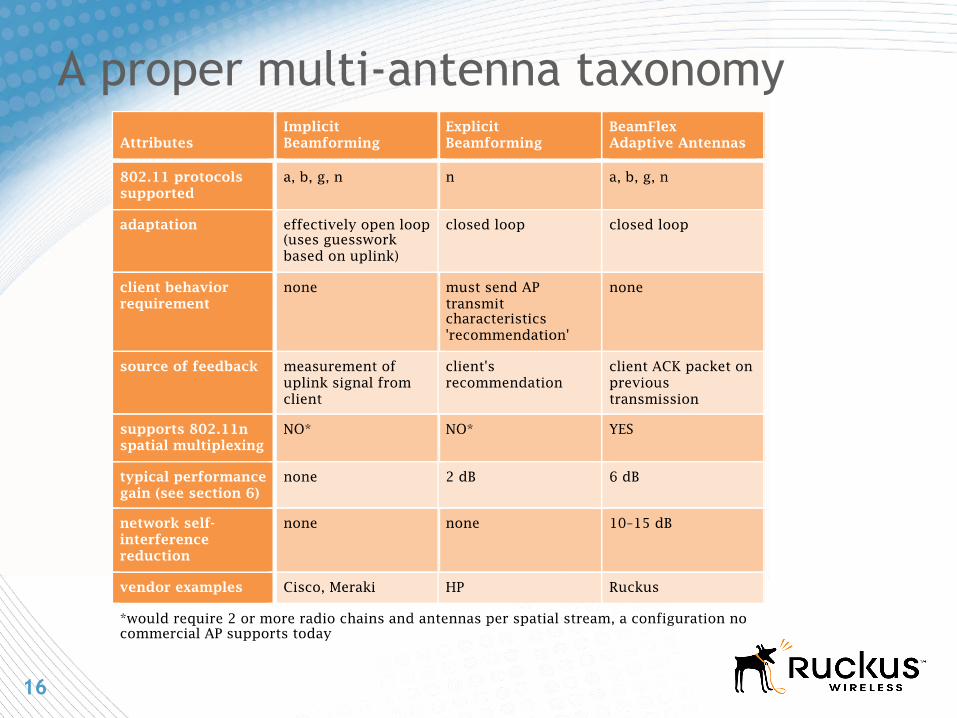
A proper multi-antenna taxonomy

17
BeamFlex Antenna Advantages
BeamFlex smart antenna:
Beamforming focuses the RF energy ensuring multipath arrives in phase and provides maximum signal density = extended range and superior performance
Horizontally and vertically polarised elements offer 4000+ unique antenna patterns automatically selected on a per packet/per client basis
Attenuate interference from adjacent APs, clients and other RF sources
Cause significantly less interference to adjacent APs
Omni-directional antenna:
Cannot control interference to neighbouring APs
Multipath phasing can be a significant issue
No interference rejection
Make bad RF neighbors
Signal Gain
Up to 9dBi
Rejected Interference
Up to -17dB

18
BeamFlex™: Interference Resistance
0
1
2
3
4
5
6
7
8
9
10
0 20 40 60
0
1
2
3
4
5
6
7
8
9
10
0 20 40 60
0
1
2
3
4
5
6
7
8
9
10
0 20 40 60
iPhone 3G Client Throughput Comparison
Vendor C Ruckus Vendor B
0.3
8.7
5.5
0.1
6.7
8.3
Test House Baseline (low interference)
High Interference Location (191 active APs in 3,000m² facility)
Throughput, Mbps
Average
Time, Seconds
19
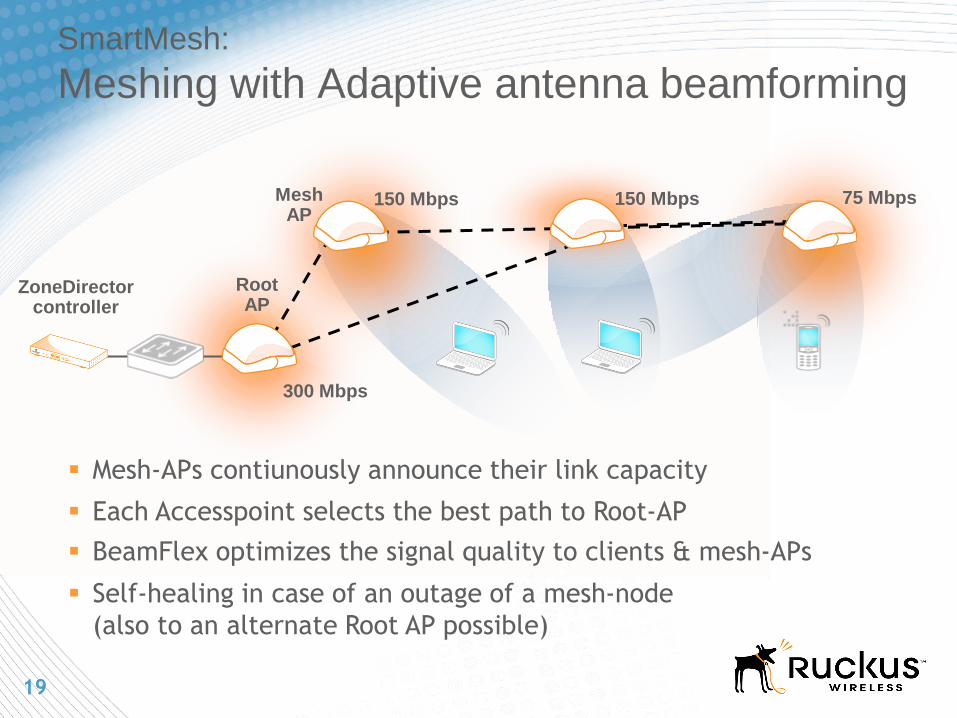
SmartMesh:
Meshing with Adaptive antenna beamforming
Mesh-APs contiunously announce their link capacity
Each Accesspoint selects the best path to Root-AP
BeamFlex optimizes the signal quality to clients & mesh-APs
Self-healing in case of an outage of a mesh-node
(also to an alternate Root AP possible)
Root AP
ZoneDirector controller
300 Mbps
150 Mbps 150 Mbps 75 Mbps Mesh AP

20
Performance varies significantly
Note: 2.4 GHz, 800 ns GI, ETSI EIRP, 15 dB fading margin for interference
and obstructions
Sources: Ruckus testing, experience.
0
20
40
60
80
100
120
140
160
180
0 5 10 15 20 25 30 35 40 45 50
[1] .11n 1x1:1 omni
[2] .11n + Explicit Beamforming (1 stream)
[3] .11n 2x2:2 omni
[4] .11n 3x3:3 omni
[5] .11n 1x1:1 + BeamFlex
[6] .11n 2x2:2 + BeamFlex
RF Technology Comparison
Peak Throughput, Mbps
Range, m

21
Net result: BeamFlex 70% better
Ruckus 3x3:2 APwith BeamFlex
4-Year Aggregate Client Throughput per AP, Terabytes
Generic 3x3:3 APwith ExplicitBeamforming
440
more capacity for client servicewith Ruckus
260
70%
22
Case Study
Wireless Broadband Deployment
Tikona India
23
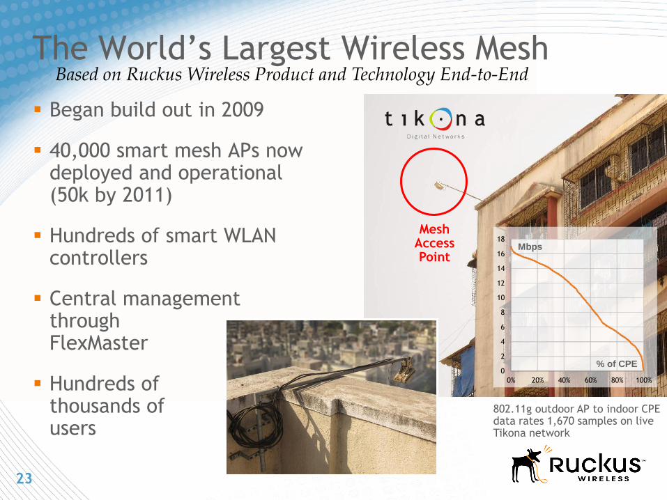
The World’s Largest Wireless Mesh
Mesh Access Point
Began build out in 2009
40,000 smart mesh APs now deployed and operational (50k by 2011)
Hundreds of smart WLAN controllers
Central management through FlexMaster
Hundreds of thousands of users
Based on Ruckus Wireless Product and Technology End-to-End
0
2
4
6
8
10
12
14
16
18
0% 20% 40% 60% 80% 100%
802.11g outdoor AP to indoor CPE data rates 1,670 samples on live Tikona network
Mbps
% of CPE
24
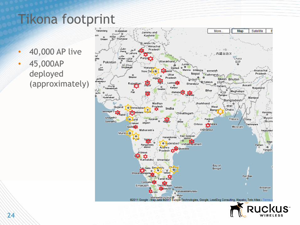
Tikona footprint
• 40,000 AP live
• 45,000AP
deployed
(approximately)

25
Large-Scale Mesh Deployment
ZoneFlex 7731 Point-to-point
802.11n backhaul
FlexMaster Remote Management
ZoneDirector WLAN Controller
MediaFlex 2211 Bridge/Repeater
Outdoor Mesh AP
50 Mbps at 10km 100 Mbps at
2km
20 Mbps at 300m/1000 ft
Backhaul POP
NOC
WBA

26
End-to-end visibility and control One NOC
Multiple cities
Tens of Thousands of access points
Hundreds of Thousands of clients

27
Active Antenna Beamforming Wi-Fi Portfolio
I N D O O R O U T D O O R
802.11n Bridge
802.11 n AP
802.11g
Single-band 802.11n
2X2 dual-band 802.11n
3X3 dual-band 802.11n
802.11g outdoor mesh
Dual-band 802.11n outdoor
802.11g outdoor mesh
Dual-band 802.11n outdoor
Strand-Mounted 802.11n 5GHz 802.11n PtP/PtMP
Autonomous, Controller-Based or Remotely Managed
802.11n wall switch
Sectorized dual-band 802.11n
Smart Wi-Fi
controllers for RF
and AP
management
Network and Subscriber Management
Highly-scalable centralized
network and element
management
ZoneDirector™ FlexMaster™

28
Thank You
Scott Reeves
Technical Director EMEA
Ruckus Wireless