
Mark Vaughn 2000 Eagle 145,164,180 - Wills Wing - Hang...
55
Eagle 145,164,180 Owner / Service Manual March 2002 - Second Edition Mark Vaughn 2000
Transcript of Mark Vaughn 2000 Eagle 145,164,180 - Wills Wing - Hang...

Eagle 145,164,180Owner / Service Manual
March 2002 - Second Edition
Mark Vaughn 2000


500 West Blueridge Ave • Orange, CA • 92865-4206 • Phone (714) 998-6359 • FAX (714) 998-0647Internet Web address: http://www.willswing.com • E-mail: [email protected]
March 2002 - Second Edition
Copyright © 2000, 2001,2002 by Sport Kites, Inc. dba Wills Wing, Inc. All rights reserved.No part of this manual may be reproduced in any form without the express written permission of
Sport Kites, Inc., dba Wills Wing, Inc.
Eagle 145,164,180Owner / Service Manual

Contents
Introduction...................................................................................................... 1Disclaimer And Warning .................................................................................... 2Technical Information And Placarded Operating Limitations .................................... 3Eagle Breakdown Procedure For Shipping And Reassembly Procedure ...................... 5Eagle Set-Up Procedure ..................................................................................... 6Eagle Pre-flight Procedure ................................................................................ 10Laying The Glider Down Flat ............................................................................ 12Setting The Glider Up Flat On The Ground .......................................................... 12Launching And Flying The Eagle ........................................................................ 13Using Wing Tufts ............................................................................................ 13Trimming Your Glider In Pitch ........................................................................... 16Speeds To Fly And Using Your Airspeed Indicator ............................................... 17Landing The Eagle ........................................................................................... 18The Vertical Stabilizer ..................................................................................... 21Abnormal Glider Configurations
Distorted Mylar Insert And Bridle Cable Snagged Under A Batten ..................... 21Eagle Breakdown ............................................................................................ 24Eagle Stability Systems ................................................................................... 26Maintenance Schedule .................................................................................... 27Removing The Sail From The Airframe And Reinstalling ....................................... 29Tuning ........................................................................................................... 31Car Top Mounting And Transport ...................................................................... 33In Closing ....................................................................................................... 33HGMA COMPLIANCE VERIFICATION SPECIFICATION SHEET................................ 34HGMA COMPLIANCE VERIFICATION SPECIFICATION SHEET................................ 35HGMA COMPLIANCE VERIFICATION SPECIFICATION SHEET................................ 36Eagle Round Control Bar ..................................................................................... IEagle Streamline Control Bar .............................................................................. IIEagle Noseplate Assembly .................................................................................IIIEagle Rear Keel ............................................................................................... IVEagle Kingpost Assembly ...................................................................................VEagle Crossbar Assembly .................................................................................. VIEagle Rear Leading Edge and Sail Adjuster ......................................................... VIIEagle Kingpost Base and CG Track ................................................................... VIIIEagle Xbar - Leading Edge Junction .................................................................... IXEagle 145 Frame Plans ......................................................................................XEagle 164 Frame Plans .................................................................................... XIIEagle 180 Frame Plans ...................................................................................XIV

— 1 —
IntroductionThank you for purchasing a Wills Wing glider, and welcome to the world wide family of Wills Wingpilots. We are a company of pilots and aviation enthusiasts, and our goal is to serve your flying needsnow and in the future, as we have done for pilots throughout the world since 1973.
We encourage you to read this manual thoroughly for information on the proper use and maintenanceof your Wills Wing glider. If at any time you have questions about your glider, or about any aspect ofhang gliding that your Wills Wing dealer cannot answer, please feel free to give us a call.
If you have access to the Internet, please visit us at http://www.willswing.com. The site featuresextensive information about Wills Wing gliders and products, a Wills Wing Dealer directory, a compre-hensive list of service and technical bulletins, current editions of owners manuals, our complete retailprice list, a search engine, and more.
We wish you a safe and enjoyable flying career, and, once again, welcome aboard!
Rob Kells, Mike Meier, Linda Meier, and Steve Pearson
Wills Wing, Inc.

— 2 —
Disclaimer And WarningHang gliding is a form of aviation. Like any form of aviation, its safe practice demands the consistentexercise of pilot skill, knowledge of airmanship and weather, judgment and attention at a level whichis appropriate to the demands of each individual situation. Pilots who do not possess or exercise therequired knowledge, skills and judgment are frequently injured and killed. The statistical rate atwhich fatalities occur in hang gliding is approximately one per thousand participants per year.
The Federal Aviation Administration does not require a pilot’s license to operate a hang glider. Hanggliders and hang gliding equipment are not designed, manufactured, tested or certified to any state orfederal government airworthiness standards or requirements. Wills Wing hang gliding products arenot covered by product liability insurance. You should never attempt to fly a hang glider withouthaving received competent instruction. We recommend that you not participate in hang gliding unlessyou recognize and wish to personally assume the associated risks.
Please fly safely.
Wills Wing, Inc.
— 3 —
Technical Information And Placarded Operating LimitationsThe Eagle has been tested and found to comply with the HGMA Airworthiness Standards in effect asof the testing. These standards require:
1. A positive load test at root stall angle of attack at a speed equal to at least the greatest of:
a. 141% of the placarded maximum maneuvering speed
b. 141% of the placarded maximum rough air speed
c. 123% of the placarded speed never to exceed
for at least three seconds without failure.
2. A negative 30 degree angle of attack load test at a speed equal to at least the greatest of:
a. 100% of the placarded maximum maneuvering speed
b. 100% of the placarded maximum rough air speed
c. 87% of the placarded speed never to exceed
for at least 3 seconds without failure.
3. A negative 150 degree angle of attack load test at a speed equal to at least the greater of 30m.p.h. or 50% of the required positive load test speed for at least 3 seconds without failure.
4. Pitch tests at speeds of Vs, Vne, and (Vs + Vne)/2 which show the glider to be stable from trimangle to 20 degrees below zero lift angle at Vs, and from trim angle to 10 degrees below zero liftangle at (Vs+Vne)/2, and from 10 degrees above zero lift angle to zero lift angle at Vne.
5. Flight maneuvers which show the glider to be adequately stable and controllable throughout thenormal range of operation.
The Eagle has been designed for foot launched soaring flight. It has not been designed to be motor-ized, tethered, or towed. It can be towed successfully using proper towing procedures. Pilots wishingto tow should be USHGA skill rated for towing, and should avail themselves of all available informa-tion on the most current proper and safe towing procedures. Suggested sources for towing informationinclude the United States Hang Gliding Association and the manufacturer of the towing winch / orequipment being used. Wills Wing makes no warranty of the suitability of the glider for towing.
Flight operation of the Eagle should be limited to non aerobatic maneuvers; those in which the pitchangle will not exceed 30 degrees nose up or nose down from the horizon, and the bank angle will notexceed 60 degrees. The Eagle is generally resistant to spinning, but will spin from a stalled turn if thepilot applies positive pitch control aggressively in combination with roll control input so as to rolltowards the high wing. Recovery from a spin requires unstalling of the wing, and it is thereforeimportant that in the event of a spin, no application of nose up pitch control be held. The Eagle willrecover from a spin once control pressures are relaxed. As the nose lowers and the angle of attack isreduced, the stall will be broken and the spin will stop. However, such recovery will consume signifi-cant altitude, and will result in the glider assuming an unpredictable heading. Recovery from a spinmay therefore involve a flight trajectory which intersects the terrain at a high rate of speed. Anaggravated spin could result in loss of control, in flight inversion, and structural failure. Therefore noattempt should ever be made to deliberately spin the glider.

— 4 —
The maximum steady state speed for a prone pilot in the middle of the recommended weight range fullforward on the control bar is approximately 42 m.p.h. for the Eagle. The placarded speed never toexceed for the Eagle is 53 m.p.h. (164) or 48 mph (145 & 180), and the maneuvering / rough air speedis 46 m.p.h. (164) and 42 mph (145 and 180). The Eagle can be flown in steady state high speed flightwith the pilot full forward over the bar without exceeding the VNE speed. Abrupt maneuvers maycause the glider to exceed VNE, and abrupt maneuvers should not be made from speeds above 46m.p.h. (Eagle 164) or 42 mph (Eagle 145, 180).
The stability, controllability, and structural strength of a properly maintained Eagle have been deter-mined to be adequate for safe operation when the glider is operated within all of the manufacturerspecified limitations. No warranty of adequate stability, controllability, or structural strength is made orimplied for operation outside of these limitations.
The stall speed of the Eagle at maximum recommended wing loading is 25 m.p.h. or less. The top(steady state) speed at minimum recommended wing loading for a prone pilot with a properly designedand adjusted harness is at least 35 m.p.h..
All speeds given above are indicated airspeeds, for a properly calibrated airspeed indicator mounted inthe vicinity of the pilot. Such an airspeed indicator is available through your Wills Wing dealer.
The recommended hook in pilot weight range for the Eagle is 130 - 200 lbs (145); 150 - 250 lbs (164);or 175 - 275 lbs (180).
Be advised that pilots with hook in weights within 20 lbs of the minimum recommended will find theEagle somewhat more demanding of pilot skill to fly, and that pilots with hook in weights of more than130% of the minimum recommended will experience some relative degradation of optimum sink rateperformance due to their higher wing loading.
Direct supervision by a qualified instructor, or a minimum USHGA Novice (II) level of pilot profi-ciency in combination with an instructor supervised transition to the Eagle is required to fly the Eaglesafely.
Operation of the glider by unqualified or under qualified pilots may be dangerous.
Operating the Eagle outside of the above limitations may result in injury and death. Flying the Eagle inthe presence of strong or gusty winds, or turbulence may result in loss of control of the glider whichmay lead to injury and death. Do not fly in such conditions unless you realize and wish to personallyassume the associated risks. Wills Wing is well aware that pilots have, and continue to performmaneuvers and fly in conditions which are outside the recommended operating limitations statedherein. Please be aware that the fact that some pilots have exceeded these limitations in the pastwithout dangerous incident does not imply or insure that the limitations may be exceeded without risk.We do know that gliders which meet all current industry standards for airworthiness can and dosuffer in flight structural failures, both as a result of turbulence, and as a result of various maneuversoutside the placarded operating limitations, including, but not necessarily limited to aerobatics. We donot know, and cannot know, the full range of maneuvers or conditions which may cause the pilot’ssafety to be compromised, nor can we test the glider in all possible circumstances.

— 5 —
Eagle Breakdown Procedure For Shipping And Reassembly ProcedureThe Eagle can be broken down to approximately 2/3 of it's normal length by removal of the rearleading edges. The rear leading edge is slotted at its forward end, such that the slots engage aroundthe clevis pin which is mounted in the forward section.
To break down the leading edges follow these steps1. Lay the glider on the ground or floor, unzip and remove the bag and remove the Velcro ties. Undo
the velcros which hold the sail around the sail mount plug and pull the sail rearward at each tip todismount the sail from the rear leading edge. You may use a large, flat bladed screw driver to prythe sail mount webbing away from the slotted endcap. Take care that the screwdriver does nothave a sharp edge which might cut or damage the webbing.
2. Obtain an indelible marker. Mark the rear leading edges left and right (remember that left andright are reversed if the glider is lying “on it’s back”, upside down. Push the sail up to where youhave uncovered the point where the rear leading edge exits the front. Trace around the circumfer-ence of the 50 mm rear leading edge just aft of the 52 mm oversleeve so as to mark the point atwhich the rear leading edge is fully engaged in the front.
3. Scribe a line along the leading edge which crosses the front to rear leading edge junction. Thiswill help to align the rear leading edge during reassembly.
4. Spray silicone spray lubricant on the rear leading edge at the point where it exits from the front.
5. Pull the rear leading edge straight aft to disengage it from the front. Put tape or otherwise protectthe sharp edges of both the front and rear leading edge tubes from damaging the sail duringtransport..
6. Replace the sail mount ties, zip up the bag, and carefully fold the rear of the glider over againstthe front.
Remounting the rear leading edges1. Make sure you are mounting the correct leading edge rear into the correct front (check the “right”
/ “left” designation).
2. Spray the forward six inches of the rear leading edge with silicone spray lubricant.
3. Slide the rear leading edge into the front, lining up the rotational alignment marks you madeduring breakdown, until the rear engages fully in the front leading edge, as indicated by thecircumferential scribe made at the exit point of the rear leading edge during breakdown.
4. Pull the sail down the leading edge.
5. Remount the sail to the rear leading edge, making sure to align the inner sail mount webbingsquarely in the slot and attach the securing velcros.
You may find it helpful to use a large, flat bladed screw driver to pry the sail mount webbing over theend of the leading edge tube and into the slot. Take care not to damage the webbing.
— 6 —
Eagle Set-Up ProcedureThe Eagle has been specially designed to set up quickly and easily either on the control bar or flat onthe ground. We will first cover the steps for setting up on the control bar.
1. With the glider in the bag, lay the glider on the ground, zipper up, with the nose into the wind. Ifthere is more than five m.p.h. of wind, or if the wind is gusty, turn the glider 90 degrees to thewind direction.
2. Undo the zipper, remove the battens, and remove the control bar bag.
3. Separate the control bar legs.
a. If the glider is equipped with a folding basetube:
i. Straighten the fold in the folding basetube.
ii. Preflight the folding basetube center hardware at this time, checking that the nuts and coilspring pins are secure, and that the tangs are straight and in good condition.
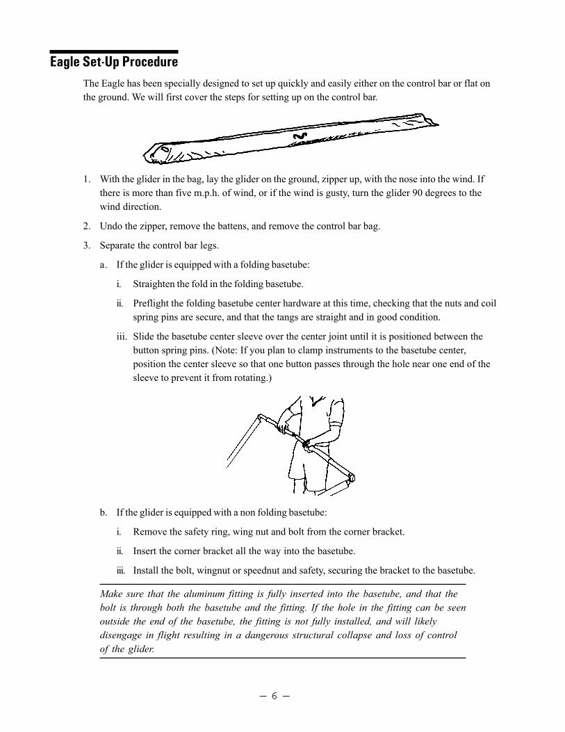
iii. Slide the basetube center sleeve over the center joint until it is positioned between thebutton spring pins. (Note: If you plan to clamp instruments to the basetube center,position the center sleeve so that one button passes through the hole near one end of thesleeve to prevent it from rotating.)
b. If the glider is equipped with a non folding basetube:
i. Remove the safety ring, wing nut and bolt from the corner bracket.
ii. Insert the corner bracket all the way into the basetube.
iii. Install the bolt, wingnut or speednut and safety, securing the bracket to the basetube.
Make sure that the aluminum fitting is fully inserted into the basetube, and that thebolt is through both the basetube and the fitting. If the hole in the fitting can be seenoutside the end of the basetube, the fitting is not fully installed, and will likelydisengage in flight resulting in a dangerous structural collapse and loss of controlof the glider.
— 7 —
Do not insert the fitting at an angle, and do not force the fitting into the basetube if it does not slidein freely. Check for dirt or damage to the fitting or the inside of the basetube. If the fitting isforced into the basetube, it may be impossible to remove. See your dealer if the fitting becomesdifficult to install or remove.
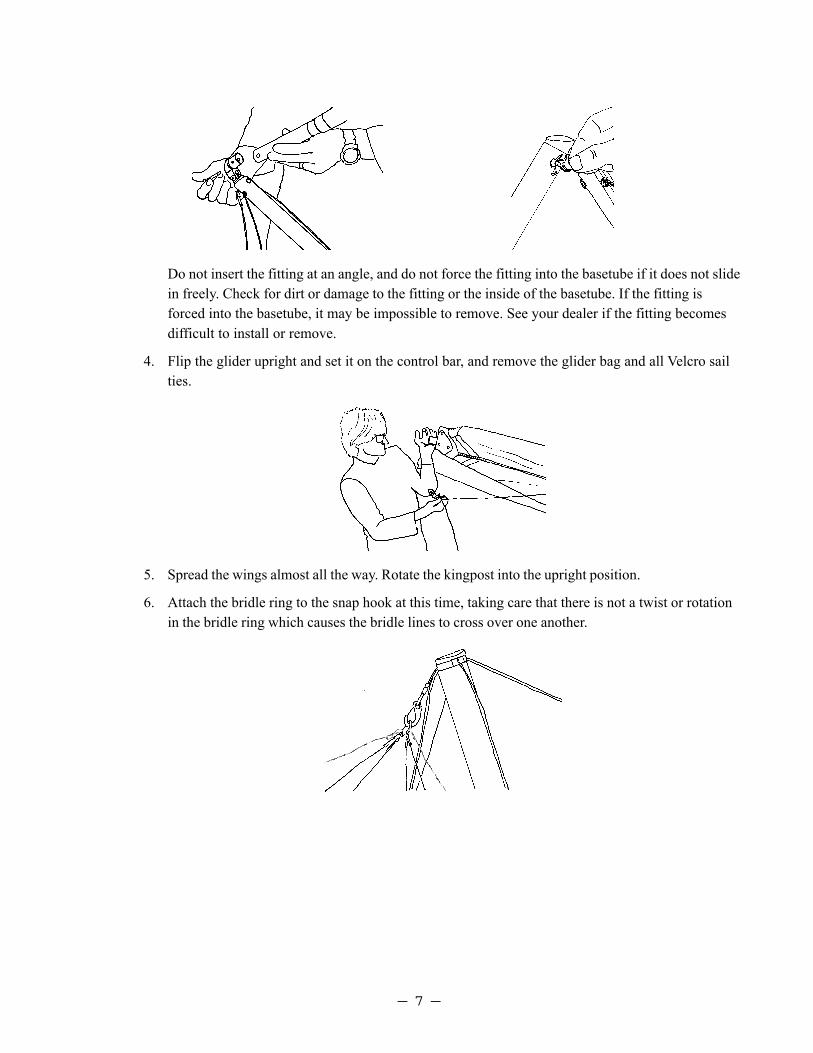
4. Flip the glider upright and set it on the control bar, and remove the glider bag and all Velcro sailties.
5. Spread the wings almost all the way. Rotate the kingpost into the upright position.
6. Attach the bridle ring to the snap hook at this time, taking care that there is not a twist or rotationin the bridle ring which causes the bridle lines to cross over one another.

— 8 —
7. Lay out the battens and check each batten for symmetry against the corresponding batten fromthe other wing.Wills Wing convention is that black tipped battens go in the right wing andwhite tipped battens in the left, except that both the straight #1 plug-on battens have black tips.
8. Install the 4 longest cambered top surface battens in the sail. Each batten is secured by a doubleloop of the batten string (double purchase). Order of insertion is longest to shortest, from the rootout. Spread the wings all the way and check all cables for any twisted thimbles or tangled cables.
Take care while inserting the inboard battens that the rear edge of the mylar insertdoes not catch on the batten tip and become folded under. If this does happen, pullthe batten out part way until the front of the batten is well behind the mylar pocket.Smooth the mylar insert down, and re-insert the batten. If the mylar insert is foldedunder it will cause a bump in the surface of the leading edge portion of the sail.This can cause a dangerous degree of premature airflow separation or "stall" inflight, and can make the glider difficult to control. Please read the section "DealingWith Abnormal Flight Configurations" in the flying section of this manual.
9. At the rear of the keel, tension the crossbar by pulling on the perlon rope loop which is attached tothe sweep wire keyhole channel. Drop the keyhole channel all the way down over the top portionof the keyhole collar, and let it slide forward into the locked position.
Never install the keyhole channel or keyhole tangs onto the keyhole bolt without makingabsolutely sure that they are fully engaged on the narrow neck of the bolt and slidforward into the fully locked position. An in-flight disengagement of this attachment willcause a complete loss of structural support of the glider and a total loss of control.
10. Remove the tip cover bags, and install the remaining cambered battens.
— 9 —
11. Install the straight plug-on #1 battens. Insert one end of the batten through the hole in the bottomsurface at the tip. This end plugs onto the stud on top of the leading edge, and the batten string issecured double purchase to the other end.
12. At this time preflight the following from the open end of the wingtip:
a. The sail mount webbing - make sure that the inner loop of webbing is laying flat in the bottomof the slot in the sail mount endcap.
b. The number one batten clevis pin and safety.
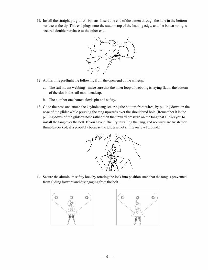
13. Go to the nose and attach the keyhole tang securing the bottom front wires, by pulling down on thenose of the glider while pressing the tang upwards over the shouldered bolt. (Remember it is thepulling down of the glider’s nose rather than the upward pressure on the tang that allows you toinstall the tang over the bolt. If you have difficulty installing the tang, and no wires are twisted orthimbles cocked, it is probably because the glider is not sitting on level ground.)
14. Secure the aluminum safety lock by rotating the lock into position such that the tang is preventedfrom sliding forward and disengaging from the bolt.
— 10 —
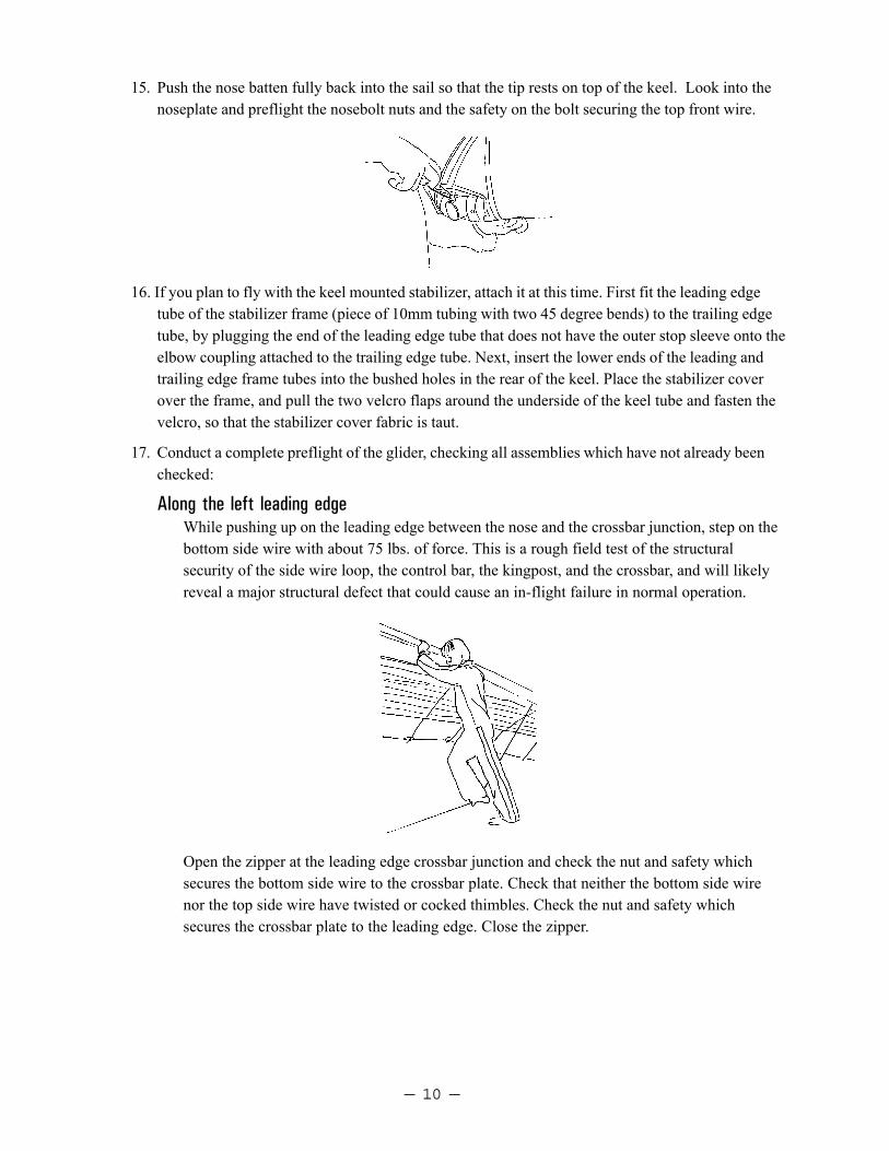
15. Push the nose batten fully back into the sail so that the tip rests on top of the keel. Look into thenoseplate and preflight the nosebolt nuts and the safety on the bolt securing the top front wire.
16. If you plan to fly with the keel mounted stabilizer, attach it at this time. First fit the leading edgetube of the stabilizer frame (piece of 10mm tubing with two 45 degree bends) to the trailing edgetube, by plugging the end of the leading edge tube that does not have the outer stop sleeve onto theelbow coupling attached to the trailing edge tube. Next, insert the lower ends of the leading andtrailing edge frame tubes into the bushed holes in the rear of the keel. Place the stabilizer coverover the frame, and pull the two velcro flaps around the underside of the keel tube and fasten thevelcro, so that the stabilizer cover fabric is taut.
17. Conduct a complete preflight of the glider, checking all assemblies which have not already beenchecked:
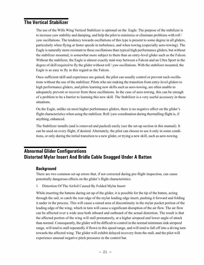
Along the left leading edgeWhile pushing up on the leading edge between the nose and the crossbar junction, step on thebottom side wire with about 75 lbs. of force. This is a rough field test of the structuralsecurity of the side wire loop, the control bar, the kingpost, and the crossbar, and will likelyreveal a major structural defect that could cause an in-flight failure in normal operation.
Open the zipper at the leading edge crossbar junction and check the nut and safety whichsecures the bottom side wire to the crossbar plate. Check that neither the bottom side wirenor the top side wire have twisted or cocked thimbles. Check the nut and safety whichsecures the crossbar plate to the leading edge. Close the zipper.

— 11 —
Along the trailing edge, left wingCheck that there are no tears in the sail material along the trailing edge.
Check that all batten strings are properly secured.
Check that the bridles are properly engaged, with the plastic retainer balls fully seated againstthe grommet, and that no bridle cable is hooked underneath a more inboard batten.
Wrong!
From the rear keelCheck the hang loop bolt and nut that secures the hang loop to the kingpost.Check the 1/4" rivet which secures the kingpost to the bracket..Check the condition of the sweep wires in the vicinity of the kingpost base bracket.Check the kingpost top for proper attachment of the bridles and condition of the top rear wireand bridle pigtail wire.Check again that the keyhole channel is fully engaged and locked to the keyhole bolt.
Along the trailing edge, right wingSame as for left wing.
At the right tipSame as for left tip.
Along the right leading edgeSame as for left leading edge.

— 12 —
Under the glider, at the control barSight down the downtubes, making sure that they are straight.
Check the cables at the control bar corners, making sure there are no kinks or twistedthimbles. Check for proper installation of all nuts and safety rings at the control bar corners.
Check the control bar apex bracket hardware, including the clevis pin safeties, the control bartop plug bolts and nuts, and the elbow to apex bracket clevis and safety.
Check the main and backup hang loops, that they are properly installed in the proper positionand that they are in good condition.
Check the clevis pin and safety that secure the kingpost base in the CG adjustment track.
Un-zip the bottom surface center zipper and check the xbar center hardware. Make sure thesweep wires thimbles are not cocked or twisted on the crossbar center hinge brackets. Makesure the center hinge bolt is secure. Zip up the center zipper.
At the noseCheck the security of all nuts at the noseplate, and that the safety ring is in place above thenut which holds the top front wire. Check that the keyhole tang safety is properly secured.
Laying The Glider Down FlatOnce the glider is assembled it can easily be laid down flat on the ground.
1. Pivot the keyhole anchor safety and release the bottom front wires from the noseplate.
2. Rock the glider forward so that the basetube folds rearward and underneath the glider as yougently lower the glider to the ground.
Reverse the procedure to set the glider upright again.
Setting The Glider Up Flat On The GroundIn areas where the ground is not rocky and when there are strong winds, you may wish to set up theglider flat on the ground. This is easy to do, and relatively few parts of the set up procedure aredifferent from what has been described.
1. After unfolding and securing the control bar, flip the glider over right side up with the control barstill flat under the glider.
2. Spread the wings and install all the battens. (Note: Perform all the normal preflight operations asdescribed above).
3. Tension the crossbar.
4. When ready, raise the nose of the glider while pulling on the bottom front wires to raise the gliderup onto the control bar. Secure the bottom front wires as described above.

— 13 —
Launching And Flying The Eagle1. If the wind is more than 10 m.p.h. or gusty you should have an assistant on your nose wires on
launch, and, if necessary, an assistant on one or both side wires. Make sure all signals are clearlyunderstood. Do a hang check immediately prior to launch. The angle at which you hold the glidershould depend on the wind speed and slope of the terrain at launch; you want to achieve a slightpositive angle of attack at the start of your run.
2. Run aggressively on launch and ease the bar out for lift off.
3. The flying characteristics of the Eagle are typical of a medium performance flex wing. Make yourfirst flights from a familiar site in mellow conditions to give you time to become accustomed to theglider.
4. We recommend that you hang as close as possible to the basetube in the glider - this will give youlighter control pressures and better control.
Using Wing TuftsYour Wills Wing glider has been equipped from the factory with short yarn tufts on the top surface ofeach wing. The shadow of these tufts will be visible through the sail. The tufts are useful for indicat-ing the local reversal of the airflow which is associated with the onset of the stall in that portion ofthe wing. You can use these tufts, as described below, to help determine when you are flying atminimum sink airspeed.
There are two important airspeeds with which all hang glider pilots should be intimately familiar;minimum sink airspeed (hereinafter referred to as VMS) and minimum controllable airspeed (MCA).The most important of these two is MCA. Minimum sink airspeed is that speed at which your descentrate is the slowest possible. It is the speed to fly when you want to maximize your climb rate in lift, orslow your rate of descent to a minimum in non lifting air. (You would normally not fly at VMS insinking air; the strategy there is normally to speed up and fly quickly out of the sink. By minimizingyour time spent in the sinking air you minimize altitude lost, even though you have momentarilyincreased your sink rate by speeding up.)
Minimum controllable airspeed is that speed below which you begin to rapidly lose effective lateralcontrol of the glider. Recognition of this speed and its implications is a more subtle problem thanmany pilots realize. We have seen several instances of pilots who were having a lot of trouble flyingtheir gliders simply because they were unknowingly trying to fly them too slowly; below the speed atwhich the glider responded effectively to lateral control inputs. It is our opinion that a great percent-age of hang gliding accidents are caused by inadvertent flight below MCA, and subsequent loss ofcontrol of the glider with impact preceding recovery. Such incidents are usually attributed to “stalls,”but it is not the stall per se that causes the problem, indeed the glider need not even be “stalled” in thetraditional sense.
There is no necessary cause and effect relationship between minimum sink speed and minimumcontrollable airspeed. VMS is determined primarily by the wing loading and span loading, the wingplanform, the wing section characteristics, etc. MCA is influenced most heavily by the tension in thesail; how much “billow” the glider has. However, in your Wills Wing glider, as in most hang gliders,

— 14 —
MCA and VMS evolved towards a common value during the design and development of the glider.This is so because if the wing is tuned so tight that minimum controllable airspeed is at a higher speedthan minimum sink speed, then effective sink rate performance can be improved by loosening the wingso as to lower the minimum controllable airspeed. Conversely, if minimum controllable airspeed isreached at a speed below that of minimum sink, the wing can usually be tightened so as to improveglide performance without significant sacrifice in other areas.
Using wing tufts to find the minimum sink speed of your gliderOn a flex wing hang glider, the wing experiences a gradual and progressive stall, and differentspanwise stations of the wing stall at different angles of attack. A hang glider wing does not necessar-ily stall first in the root or center section. It is true that because of wing twist the root section is at thehighest angle of attack relative to the remote free stream airflow, but other factors influence the stallpropagation on the wing. Most flex wing hang gliders stall first somewhere outboard of the root oneach wing, approximately one fifth to one third of the way out from the root to the tip, about whereyour tufts are located. As the angle of attack is raised further, the stall propagates both outwardtowards the tips and inward towards the root. If you wish to observe the stall propagation across thewhole wing on your glider, you can cut some more tufts from knitting yarn, about 3-4" long, and tapethese to the top surface of your sail across the rest of the span.
During normal flight the flow will be chordwise along the wing, and the tufts will point towards thetrailing edge. When the wing stalls, the tufts will reverse direction, indicating the local flow towardsthe leading edge.
At the first onset of stall, the tufts will indicate the impending separation by first wiggling, and thendeflecting spanwise, before they fully reverse and point forward. The first onset of stall occurs wellbefore the familiar “stall break” in which the glider pitches uncontrollably nose down to recover fromthe stall. By the time the stall break occurs, all tufts but those farthest outboard and those farthestinboard will have indicated reversed flow.
The first onset of midspan stall as indicated by the first tickling of the tufts indicates that you havereached the angle of attack corresponding to the glider’s minimum sink airspeed. This will also bevery close to the glider’s minimum controllable airspeed. To find the glider’s minimum sink speed,fly the glider in smooth air, early in the morning or late in the afternoon. When you are well away

— 15 —
from the terrain, and well clear of other aircraft, look up at the wing tufts while you very graduallyreduce the speed of the glider. Note the speed at which the first tuft first begins to wiggle just prior toblowing spanwise toward the tip. (If the tufts contain static electricity, they may not show this lateralwiggle prior to reversal. However, you may get other clues to the beginning of separation, such asslight flutter or rumble in the top surface of the sail.) This is your speed for minimum sink rate.Familiarize yourself with the position of the control bar relative to your body at this speed, with thesound and feel of the wind, with the reading on your airspeed indicator, and with the feel of the gliderin terms of pitch and roll pressures. Most of the time when you are flying it will not be practical tolook up for extended periods of time at your tufts. That is why familiarization with these other, moreaccessible indicators is important.
After finding your minimum sink speed, experiment with roll control response at speeds just above andjust below this speed to find the value of MCA and the corresponding bar position and other indicatorsfor this speed. Realize that your effective MCA is going to be higher and higher as the air becomesmore and more turbulent; control response that is perfectly adequate in smooth air will not be goodenough in rougher air. Try flying the glider with the midspan tufts fully reversed; you will probably findthat the glider is somewhat controllable, but only with a lot of physical effort. Note that both MCA andVMS come well before the glider actually “stalls” in the traditional sense, i.e. pitches uncontrollablynose down. You may also be able to sense, or your vario may tell you that although the glider has not“stalled” (pitched nose down) your sink rate has increased significantly. In this mode the glider is“mushing.”
Once you have familiarized yourself with the glider’s characteristics in this range of speeds, you willnot need to look at the tufts very often. You will know from bar position and bar pressure, and fromthe sound and feel of the relative wind when you are at your minimum sink / minimum controllableairspeed. In general, you should not fly your glider below this speed. Be aware, however, that whenyou are flying at minimum sink in thermal gusts and turbulence, you will experience gust inducedseparation of the airflow which will periodically cause the tufts on your sail to reverse.
Of course in a turn, your minimum sink speed goes up because you are banked, and the bank effec-tively increases your wing loading which increases your flying speed for any angle of attack. But notethis: The tufts indicate angle of attack, without regard to airspeed! Therefore, if you practice flyingvarious bank angles in smooth air (while well away from any terrain or other gliders) and watch yourtufts (on the inside wing, which will be at the highest angle of attack) you will get a feel for the wayyour minimum sink speed varies at varying bank angles.
One final caution: from time to time a tuft may to stick completely to the sail, and fail to properlyindicate the direction of local flow. This may result from static buildup, or from the fine threads ofthe yard becoming caught on a seam or some dirt or imperfection in the sail. The tuft may stick whileindicating normal flow, but most often it will stick after having reversed, such that the tuft willindicate a stalled condition that does not exist. One clue in this situation is to note whether or not thetuft is wiggling. Since flow reversal occurs during a turbulent separated flow, a reversed tuft shouldbe wiggling rapidly. If it is not, it is probably stuck. A tuft indicating normal flow will not usuallywiggle. An occasional application of silicone spray to the tufts, and making sure that they are posi-tioned so that they cannot catch on any seam will minimize the problem of sticking.

— 16 —
Trimming Your Glider In PitchThe fore and aft location along the keel of your hang point is commonly (if mistakenly) referred to asyour “CG location.” The location of this hang point will, all other things being equal, determine atwhat angle of attack and airspeed your glider will naturally tend to fly (or trim), and therefore howmuch bar pressure there is to pull in from trim to a given faster speed, or how much pressure there isto push out from trim to a given slower speed. The farther forward your hang point is, the faster theglider will trim, the less effort will be required to fly fast, and the more effort will be required to flyslow. It is usually best to trim the glider somewhere between minimum sink airspeed and perhaps 3 - 5m.p.h. above that. Hang loop fore and aft position is adjusted by moving the kingpost base bracketforward or aft in the CG adjustment track. First, carefully note where the base bracket is presentlymounted. Remove the safety and clevis pin which secures the base bracket in the track, re-positionthe base bracket as desired, and re-install the clevis and safety ring. You may find it very helpful tohave someone else holding and maneuvering the kingpost from above, while standing behind thetrailing edge of the glider while you manipulate the kingpost from below the sail.
We recommend that you not stow your glider bag, or any other cargo on the glider.The practice of attaching your glider bag to the keel, for example, can drasticallyalter the pitch trim and static balance of your glider, and adversely affect its flyingand landing characteristics. The best place to carry your glider bag or other cargois in your harness.
In the absence of the use of tufts, it has become common for pilots to talk about bar position, or aboutindicated airspeed, when trying to communicate how to trim a glider properly or how to fly a glider atthe proper speed for a given situation. The problem is that these methods are unreliable and inconsis-tent from one pilot to another even on the same glider. The angle at which your harness suspends yourbody in your glider has a great deal to do with your perception of the bar “position” relative to yourbody. Airspeed indicators vary in their indicated airspeed depending on the make of the instrument,its calibration, any installation error, etc. The use of tufts gives you an absolute first hand indicationof the actual aerodynamic event associated with two critically important airspeeds on your glider. It isa potentially useful tool that may improve your flying.

— 17 —
Speeds To Fly And Using Your Airspeed IndicatorThe optional Wills Wing Hall Airspeed Indicator has been specially designed to help you fly your Eagleat the proper speeds for optimum safety and performance.
There are four color coded bands on the ASI:
White: This is the range from 20 m.p.h. to 30 m.p.h.. This is the normal flying speed range. Whilethermalling or climbing flying in lift, try to keep your speed within the lower half of this range.For gliding in light sink or light headwind, you will want to fly in the upper half of this range.
Green: The top of the green region represents the placarded maximum rough air and maximummaneuvering speeds. This speed of 46 m.p.h. should not be exceeded except in smooth air, and noabrupt large control deflections should be used above this speed. In heavy sink or strongheadwinds it is recommended that you keep the airspeed “in the green” for best penetration andglide ratio over the ground.
Yellow: This region represents the upper speed range between maximum rough air / maximummaneuvering speed and the speed never to exceed. You should fly in this range only in smooth airas described above.
Red Line: This is your never to exceed speed. At no time should you fly faster than this speed.
Color Coding
53 mph - Red46 - 53 mph - Yellow30 - 46 mph - Green
The design of the Hall type airspeed indicator involves using a ram air versus staticpressure differential to raise a disc in a tapered tube against the force of the weightof the disc. Because of this the ASI has certain operating limitations:
a. It is only accurate in one G flight. If you are turning at a bank angle of more than 30 degrees,the ASI will read artificially low as a result of the G loading of the turn. Reliance on the ASI forlimiting airspeeds in high banked sustained spiral maneuvers will likely cause you to exceed theplacarded speed limitations of the glider and will compromise your safety.
b. It is only accurate when within 15-20 degrees of the vertical orientation.

— 18 —
Landing The EagleWe recommend using an aircraft landing approach (45 entry leg, downwind leg, base leg, and final leg)whenever possible, and we suggest that you practice making your approaches with as much precisionas possible. Under ideal conditions, landing approaches are best done so as to include a long straightfinal into the wind at a speed above best L/D speed. In a very limited field, or a field which slopesslightly downhill, when landing in light wind, you may need to make your final approach at a slowerspeed, perhaps as slow as minimum sink, in order to be able to land within the field. In winds of lessthan 5 mph, if the slope is steeper than 12:1, you should seriously consider landing downwind, uphill; orcrosswind, across the slope. Landing attempts which require slow speed approaches, maneuveringaround obstacles or into a restricted area, or downwind or crosswind landings are not recommendedfor pilots below an advanced skill level.
Standard Aircraft Approach Pattern
Entry LegDownwind Leg
Base
Final
The best way to avoid roll / yaw oscillations on approach is to fly your entire approach at a constantairspeed, and to control your touchdown point by making adjustments to the shape of your pattern. Inparticular, we recommend against the technique of make a diving turn onto final. This maneuver,sometimes called a “slipping turn” is often taught to student hang glider pilots as a way to losealtitude during the approach. While it will work reasonably well with low or medium performancelow aspect ratio gliders which have high levels of yaw stability and damping, and which are able tolose energy by diving because of the large increase in drag at higher speeds, on a high performanceglider this technique serves only to convert the energy of altitude to energy of speed, while at thesame time suddenly increasing the glider’s sensitivity to control inputs. The result is a high probabil-ity of overshooting the intended landing point and the prospect of roll / yaw oscillations which mayinterfere with a proper landing. If you develop good habits and the skills to fly precise approachesnow, it will make your transition to higher performance gliders easier later on.
Once established on a straight final approach, with wings level and flying directly into the wind, youshould fly the glider down to where the basetube is between three and six feet off the ground. At thisaltitude, let the control bar out just enough “round out” so that your descent is arrested and your flightpath parallels the ground. The remainder of your approach will consist of bleeding off excess speedwhile paralleling the ground and keeping the wings level and the nose into the wind until it is time to“flare” for landing.
Prior to the landing flare your body position should be generally upright, but slightly inclined for-ward, with your head and shoulders forward of your hips and your legs and feet trailing slightly behind.

— 19 —
Your hands should be at shoulder width and shoulder height on the uprights. You should be relaxed,with a light grip on the bar, and your weight should be fully supported in your harness and not at all byyour arms. There are several options for when to make the transition from prone to this uprightposition. Some pilots favor going upright with both hands moving to the downtubes while still at altitudeprior to the start of the approach. Others transition at the start of the approach to a semi uprightposition with one hand on a downtube and one hand on the basetube, and complete the transition bymoving the other hand to the downtube just a few seconds prior to flare. Still others fly with bothhands on the basetube until established on final glide, and then transition one hand at a time to thedowntubes prior to flare.
Whichever method you use, there are a few important principles to observe. The first is that youshould not make any change in hand position unless you are flying at or very near trim speed. Atspeeds faster than trim, you will be holding the bar in in pitch against substantial force, and if you letgo to move your hand the glider will pitch up and roll towards your remaining hand. The second isthat while moving either hand, you have no control over the glider. You should move only one hand ata time. Even so, if you can’t make the transition in the position of each hand quickly and reliably, youshould transition both hands while at altitude, before you start your approach. Otherwise, if you failto make a quick transition, you could be out of control close to the ground, and suffer a turbulenceinduced change in heading or attitude without sufficient time to recover. Many pilots make themistake of trying to change position while flying fast and close to the ground, and experience adangerous loss of control as a result. A third principle to observe is that if you are using a “pod” typeharness, you should unzip and confirm that your legs are free to exit the harness at least 500 feetabove the ground and before you start your approach. If there is any problem finding the zipper pull,or dealing with a stuck zipper, you don’t want to have to try to fix that problem while also flying theapproach.
Once established on a wings level short final, into the wind, body upright and with both hands on thedowntubes, your final concern is the timing and execution of the landing flare. The goal is to arrive onthe ground, on your feet, under control with the glider settling on your shoulders. If the wind is 15 mphor more, you will not really execute a flare at all; you will simply slow to minimum flying speed, put afoot down, and step onto the ground. In lighter winds, you will want to use some combination of a finalnose up flare, and running out your landing, in order to finish the flight on your feet with the glidersettling on your shoulders. The lighter the wind, the stronger should be both your flare and your run.
The traditional method of landing in light or no wind calls for a sharp, aggressive flare at preciselythe correct moment. This technique works fine when done correctly, but it’s not easy to get the timingjust right. Flare too early and you will climb, and then fall with the nose pitching down. Flare too lateand you won’t get the nose up enough to stop your forward motion, and the glider may nose into theground as you run into it from behind.
The flare timing process is made much easier by using a combination of a “crescendo flare” and a runout of the landing. As you bleed off speed on final, flying just above the ground, you are at firstletting the control bar out towards its trim position. As the glider reaches trim speed, which willnormally be one to three mph above stall speed, you begin to gently push the bar out to keep theglider from settling. At this point it is almost time to flare. As the glider enters the “mushing” range ofangles of attack, it will begin to settle in spite of your continuing to ease the bar out. This should behappening well before your arms are significantly extended. At this point begin your flare bysmoothly accelerating the rate at which you push out on the bar. At the same time, draw one leg

— 20 —
forward, put a foot down, and start to run as hard as you can. This run should be very much like anaggressive take off run – your body should be leaning forward into the run and you should be drivingwith your legs. The difference here is that while you are leaning into your run and driving forwardwith your legs, your arms are extending fully from your shoulders, pushing out, and what feels likeupwards, on the control bar in an accelerating, “crescendo” flare.
Done correctly, this type of flare / run combination will bring the glider quickly to a very nose highattitude, producing a great deal of drag and quickly arresting all of your forward motion. You will feelthe glider pulling you from behind, resisting your attempt to run, and as you slow down the glider willsettle gently on your shoulders. Even in no wind, you should not have to take more than a few steps.If your timing is a little early, and you feel the glider start to climb, simply stop pushing out andresume the flare when the glider again begins to settle. If your timing is a little late, your feet willtouch down a little sooner, but as long as you’re running and flaring at the same time, the glider willstay over your head or behind you.
Note: Landing in a significant wind does not require a substantial landing flare; the pilot merelyslows to near zero ground speed and touches down. The proper flare in light or no wind conditions isa dynamic action which causes a sudden and severe pitch up rotation of the glider. Pilots who havetrouble with the flare, and with the glider nosing over during landing, usually do so because of one ofthe following problems:
a. Harness leg straps too long / hanging too low below the glider, and / or hands too low on thecontrol bar. This reduces pitch authority and prevents an adequate flare.
b. Improper body position - pilot leaning back, (away from the anticipated hard landing), with feetextended in front. This moves the pilot’s center of mass forward ahead of his shoulders, effec-tively shortening the pilot’s arms and reducing flare authority. The proper position is with thepilot’s body inclined forward, with the shoulders out ahead of the pilot’s center of mass. Thinkingabout pushing “up” instead of “out” when flaring may help you to maintain the proper forwardinclined body position.
— 21 —
The Vertical StabilizerThe use of the Wills Wing Vertical Stabilizer is optional on the Eagle. The purpose of the stabilizer isto increase yaw stability and damping, and help the pilot to minimize or eliminate problems with roll /yaw oscillations. The tendency towards oscillations of this type is present to some degree in all gliders,particularly when flying at faster speeds in turbulence, and when towing (especially aero-towing). TheEagle is naturally more resistant to these oscillations than typical high performance gliders, but withoutthe stabilizer mounted, is somewhat more subject to them than an entry-level glider such as the Falcon.Without the stabilizer, the Eagle is almost exactly mid-way between a Falcon and an Ultra Sport in thedegree of skill required to fly the glider without roll / yaw oscillations. With the stabilizer mounted, theEagle is as easy to fly in this regard as the Falcon.
Once sufficient skill and experience are gained, the pilot can usually control or prevent such oscilla-tions without the use of the stabilizer. Pilots who are making the transition from entry-level gliders tohigh performance gliders, and pilots learning new skills such as aero-towing, are often unable toadequately prevent or recover from these oscillations. In the case of aero-towing, this can be enoughof a problem to be a barrier to learning this new skill. The Stabilizer is a very useful accessory in thesesituations.
On the Eagle, unlike on most higher performance gliders, there is no negative affect on the glider’sflight characteristics when using the stabilizer. Roll /yaw coordination during thermalling flight is, ifanything, enhanced.
The Stabilizer installs (and is removed and packed) easily (see the set-up section in this manual). Itcan be used on every flight, if desired. Alternately, the pilot can choose to use it only in some condi-tions, or only during the initial transition to a new glider, or trying a new skill, such as aero-towing.
Abnormal Glider ConfigurationsDistorted Mylar Insert And Bridle Cable Snagged Under A Batten
BackgroundThere are two common set-up errors that, if not corrected during pre-flight inspection, can causepotentially dangerous effects on the glider’s flight characteristics.
1. Distortion Of The Airfoil Caused By Folded Mylar Insert
While inserting the battens during set up of the glider, it is possible for the tip of the batten, actingthrough the sail, to catch the rear edge of the mylar leading edge insert, pushing it forward and foldingit under in the process. This will cause a raised area of discontinuity in the mylar pocket portion of theleading edge of the wing, which in turn will cause a significant disruption of the air flow. The air flowcan be affected over a wide area both inboard and outboard of the actual distortion. The result is thatthe affected portion of the wing will stall prematurely, at a higher airspeed and lower angle of attackthan normal. Consequently, the glider will be difficult to control in the normal minimum sink airspeedrange, will tend to stall repeatedly if flown in this speed range, and will tend to fall off into a diving turntowards the affected wing. The glider will exhibit delayed recovery from the stall, and the pilot willexperience unusual negative pitch pressures in the control bar.

— 22 —
2. Bridle Cable Snagged Under A Batten
It is possible during set up that a bridle cable may end up passing underneath the rear end of the nextinboard batten. Because it causes the cable to follow other than a direct route to its attachment at thekingpost, this significantly shortens the effective length of the bridle cable. If this condition is notcorrected during pre-flight inspection, the cable will pull up hard on the trailing edge in flight in thevicinity of the batten under which it passes. This will cause the glider to trim slower than normal, andpossibly in a stall. It will also cause a turn towards the affected wing, and it will cause the glider to begenerally less responsive in roll, and more difficult to control.
Inspection / Service Requirement:The primary and preferred solution to either of the above problems is to avoid them by always per-forming a proper pre-flight.
1. Folded Under Mylar:
In the case of a distortion due to folded under mylar, proper pre-flight procedure requires that youcarefully sight down the entire length of the top surface of the leading edge, including the fullchordwise length of the mylar pocket (the distortion described will tend to occur at the back edge ofthe mylar pocket, most often towards the root, as illustrated, and it may not be readily noticeable). Ifyou notice such a distortion, de-tension the crossbar, remove the battens in the affected area, smoothdown the mylar insert, and re-install the battens.
2. Bridle Under A Batten:
Your pre-flight should always include a full inspection of the glider from the trailing edge. During thisinspection, you should check that the bridle balls are properly seated in the grommets, that the bridlering has not been twisted prior to installation, and that no bridle line passes under an adjacent or fartherinboard batten. Note: If for any reason you de-tension the crossbar after doing your pre-flight, youmust pre-flight the bridle lines again, as this is a perfect opportunity for a bridle line to become caughtunder a batten.
— 23 —
Dealing With Configuration Abnormalities In Flight:Should one of these set up errors occur, and not be discovered and corrected during pre-flight, followthe procedures below for dealing with the situation in flight.
1. FLY THE GLIDER. This is the number one rule for any in flight aircraft emergency. Maintaindirectional control and control of airspeed and angle of attack, and maneuver away from terrainand other gliders immediately.
2. DETERMINE THE PROBLEM. While maintaining control of the glider, allow the glider to tellyou what’s wrong. If the glider is falling off on a wing and repeatedly pitching down, it is likely youhave a folded under mylar insert. If the glider is turning one direction and trying to pitch up, it islikely that the problem is a bridle cable under a batten. While maintaining control of the glider, lookup at the affected wing (the wing the glider wants to turn towards). Folded under mylar will causean indicated stall as seen by flow reversal on the tuft on that wing, even though your airspeed iswell above the normal stall speed. At the same time, you will feel negative pitch pressure in thecontrol bar if flying near minimum sink airpseed. A bridle cable under a batten will be visible toyou as you look along the trailing edge. It can also affect the local flow and therefore the wingtufts, but will usually cause a pitch up tendency, felt as positive pitch pressure in the control bar.
3. CHOOSE AN APPROPRIATE FLYING SPEED. If the problem is folded under mylar, fly faster– 30-35 mph. At a higher speed, no part of the wing will be stalled, and the glider will be relativelyeasy to control and will fly almost normally. If the problem is a bridle cable under a batten, you arebetter off to fly more slowly, at 22-25 mph, as the turn induced by the batten being pulled up is lessat lower speeds. Do not allow the glider to stall, however, as this will compromise your directionalcontrol.
4. CONFIGURE THE GLIDER FOR BEST CONTROL. If the glider is equipped with variablegeometry, set it to full loose. This will afford maximum control authority, and put the most slack inthe bridle cables.
5. FLY TO A SAFE LANDING AREA AND LAND. If you have a choice, select the largest,easiest landing area. If you have a choice, fly an aircraft pattern away from the turn in the glider.(If the glider is trying to turn right, fly a pattern with all left turns). If possible, go to full uprightposition with hands on the downtubes early in the approach, so you don’t have to change positionsat low altitude. Maintain the pre-selected flying speed for best control throughout the pattern, foras long as possible. Do not dive your approach, or slip any of your turns. Instead vary the flightpath to control you touchdown point. As you slow down on final, apply an appropriate amount ofopposite roll control against the turn as necessary to maintain straight flight. (This will be a con-tinuously increasing amount in the case of folded under mylar.) When flaring to land, apply pitchup control and roll control against the turn simultaneously, and run out the landing.

— 24 —
Eagle BreakdownBreakdown of the glider is the reverse of assembly.
1. Set the glider at 90 degrees to the wind direction. Dismount the nose batten, and pull it out about2" past the noseplate. Remove the #1 battens and 2 shortest cambered battens, roll the sail underat the tips, and install the tip cover bags.
2. Rotate the keyhole tang on the bottom of the noseplate to allow the keyhole tang to be disengaged.Disengage the tang by pulling down on the nose of the glider while pushing up with your thumbson the plastic tang handle.
3. Pull back on the crossbar sweep wire and disengage the sweep wire, de-tensioning the crossbar.
4. Remove the rest of the battens.
5. Fold the wings together, pulling the sail up over the top of the leading edges.
6. Lay the kingpost down forward against the keel.
7. Detach the bridles and stow the bridle ring at the kingpost base. One method is to tuck it under thekingpost base cover sock, over the nut which secures the hang loop bolt.
— 25 —
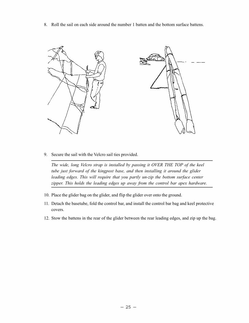
8. Roll the sail on each side around the number 1 batten and the bottom surface battens.
9. Secure the sail with the Velcro sail ties provided.
The wide, long Velcro strap is installed by passing it OVER THE TOP of the keeltube just forward of the kingpost base, and then installing it around the gliderleading edges. This will require that you partly un-zip the bottom surface centerzipper. This holds the leading edges up away from the control bar apex hardware.
10. Place the glider bag on the glider, and flip the glider over onto the ground.
11. Detach the basetube, fold the control bar, and install the control bar bag and keel protectivecovers.
12. Stow the battens in the rear of the glider between the rear leading edges, and zip up the bag.
— 26 —
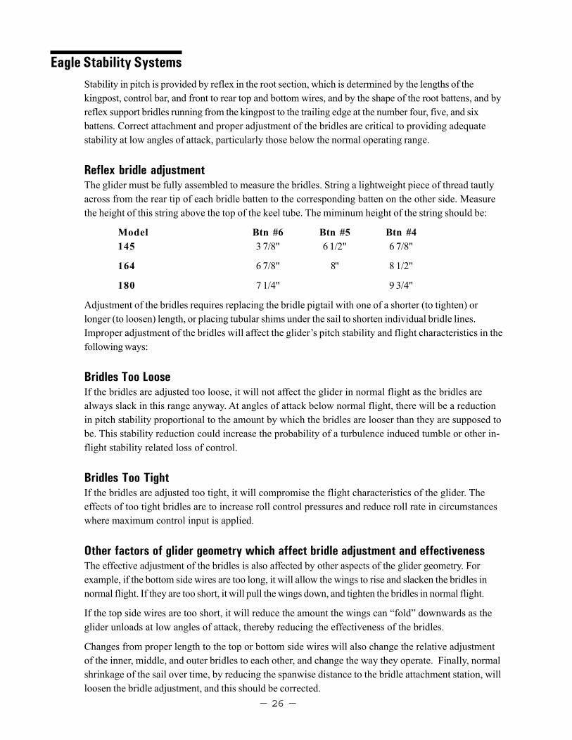
Eagle Stability SystemsStability in pitch is provided by reflex in the root section, which is determined by the lengths of thekingpost, control bar, and front to rear top and bottom wires, and by the shape of the root battens, and byreflex support bridles running from the kingpost to the trailing edge at the number four, five, and sixbattens. Correct attachment and proper adjustment of the bridles are critical to providing adequatestability at low angles of attack, particularly those below the normal operating range.
Reflex bridle adjustmentThe glider must be fully assembled to measure the bridles. String a lightweight piece of thread tautlyacross from the rear tip of each bridle batten to the corresponding batten on the other side. Measurethe height of this string above the top of the keel tube. The miminum height of the string should be:
Model Btn #6 Btn #5 Btn #4145 3 7/8" 6 1/2" 6 7/8"
164 6 7/8" 8" 8 1/2"
180 7 1/4" 9 3/4"
Adjustment of the bridles requires replacing the bridle pigtail with one of a shorter (to tighten) orlonger (to loosen) length, or placing tubular shims under the sail to shorten individual bridle lines.Improper adjustment of the bridles will affect the glider’s pitch stability and flight characteristics in thefollowing ways:
Bridles Too LooseIf the bridles are adjusted too loose, it will not affect the glider in normal flight as the bridles arealways slack in this range anyway. At angles of attack below normal flight, there will be a reductionin pitch stability proportional to the amount by which the bridles are looser than they are supposed tobe. This stability reduction could increase the probability of a turbulence induced tumble or other in-flight stability related loss of control.
Bridles Too TightIf the bridles are adjusted too tight, it will compromise the flight characteristics of the glider. Theeffects of too tight bridles are to increase roll control pressures and reduce roll rate in circumstanceswhere maximum control input is applied.
Other factors of glider geometry which affect bridle adjustment and effectivenessThe effective adjustment of the bridles is also affected by other aspects of the glider geometry. Forexample, if the bottom side wires are too long, it will allow the wings to rise and slacken the bridles innormal flight. If they are too short, it will pull the wings down, and tighten the bridles in normal flight.
If the top side wires are too short, it will reduce the amount the wings can “fold” downwards as theglider unloads at low angles of attack, thereby reducing the effectiveness of the bridles.
Changes from proper length to the top or bottom side wires will also change the relative adjustmentof the inner, middle, and outer bridles to each other, and change the way they operate. Finally, normalshrinkage of the sail over time, by reducing the spanwise distance to the bridle attachment station, willloosen the bridle adjustment, and this should be corrected.

— 27 —
Maintenance ScheduleYou should continually maintain your glider in a proper state of tune and repair to insure optimumairworthiness, performance and flight characteristics. Failure to properly maintain your glider maylead to a dangerous loss of strength, stability or control responsiveness of the glider. Following anymishap that results in damage to the glider immediately have any damaged component repaired orreplaced. We recommend that you have all such maintenance work done by your Wills Wing dealer.In addition, please follow the following maintenance schedule:
Every month1. Spray all battens with silicone spray lubricant as you install them in the glider to lubricate the
insides of the batten pockets. Do not use any other type of lubricant. Wipe off any excess siliconeso that it does not attract dirt. If you fly in a dusty or sandy environment, it will help to prolongthe life of your batten pockets if you wipe each batten with a rag before you install it in the sail.
2. Check your battens on a flat level floor against the batten diagram provided, and correct any thatdeviate from the pattern by more than 1/4".
Every six months1. Have a complete inspection performed on the glider and replace any suspension system compo-
nent that shows any wear, and any cable that shows any kinks, wear, damage, corrosion, etc.
2. Inspect all bolts for tightness, all safeties for proper installation and possible damage. Inspectplates and fittings for damage, holes in tubes for elongation.
3. Inspect the sail for wear, tears, UV damage, loose stitching, etc.
Every year1. Have the sail completely removed from the frame, and disassemble all frame components. Inspect
every part of the glider for any damage or wear. Inspect the tubes for straightness and for signs ofcorrosion. Anytime you have the sail off the frame inspect all of the batten pockets and battenpocket terminations.
2. Replace bottom side wires and hang loops.
Special circumstances1. Any time you suffer a crash or extremely hard landing you should have an “annual” inspection
done on your glider to insure that you find all damaged parts.
2. If your glider is ever exposed to salt water you will need to have the glider completely disas-sembled in accordance with the recommended annual inspection procedure. All frame parts willneed to be disassembled, including the removal of all sleeves, flushed liberally with fresh water,dried completely, and treated for corrosion inhibition with LPS-3 or other suitable agent.

— 28 —
3. Cleaning Your Sail - Keeping your sail clean will extend the life of the cloth. When cleaning theentire sail you should generally use only water and a soft brush. You may clean small spots orstains with any commercial spot remover that is labeled for use on polyester. Such cleaningagents are available at the supermarket or drug store, or you may order a cleaning solution fromWills Wing through your dealer.
A Note About Cables and Cable Maintenance:The cables which support the glider’s airframe are critical components of the glider’s structure, andmust be maintained in an air worthy condition. It is a general practice in the design of aircraft struc-tures to design to an ultimate strength of 1.5 times the highest expected load in normal service. Hangglider cables, like other structural components on the glider, are typically designed with a structuralsafety factor of only about 50% above the expected maximum load. No significant loss in cablestrength can be tolerated.
A cable with even a single broken strand must be replaced before the glider is flown again. A cablewhich has been bent sharply enough to have taken a permanent set (will not lie flat in a straight linewhen all tension is removed) must also be replaced immediately. If it is not, subsequent tensioningand de-tensioning of the cable will induce fatigue, and the cable will fail. In tests we have conducted,a cable bent one time to 90 degrees, and then loaded to the equivalent of a normal flight load 100times (corresponding to 100 or fewer flights), failed at only 56% of its original strength.
Some degree of fatigue due to repeated bending of cables is almost unavoidable in an aircraft that isassembled and disassembled with every flight. Bottom side wires are subject to the highest loads inflight, and are therefore the most critical. This is why we recommend that these wires be replacedannually, even if there is no known damage. The requirement for immediate replacement of a cableknown to have been bent or otherwise damaged supercedes this annual replacement requirement.
Replacement cables should always be obtained from the factory, or, if not from the factory, from areliable source known to use proper fabrication procedures. An improperly made cable may appearperfectly OK on visual inspection, but could fail in flight at a load much below the intended designstrength of the cable.

— 29 —
Removing The Sail From The Airframe And ReinstallingMany maintenance and repair procedures will require the removal of the sail from the frame. Pleasefollow these instructions when removing and reinstalling the sail. Please read all the instructions foreach operation before beginning.
Sail removalYou will need an unobstructed area six feet by thirty feet. Make sure the surface is clean. If it isabrasive, like rough concrete, you should either put down a protective tarp or be extremely careful notto scrape your sail.
1. Lay the glider on its back, unzip and remove the glider bag and put the battens aside. Remove thecontrol bar bag.
2. Remove the tangs that secure the sail at the nose from the bolts to which they are attached.Spread the wings slightly, undo the Velcro tabs inside the rear ends of the leading edges and thendismount the sail from the rear leading edges.
3. Unbolt the bottom side wires from the control bar. Remove the clevis pin or bolt which secures thecontrol top elbows to the apex bracket. Unbolt the bottom rear flying wires from the rear keel.Reassemble the hardware removed onto the bolts in the original order so that it doesn’t get lost.All disassembled assemblies on the glider must be reassembled in the proper order and orientation.Use the exploded parts diagrams in this manual to help you. On the bottom rear wire, the relativeposition of the washers, saddles and tangs affects the front to rear wire tension.
4. Set the control bar aside.
5. Turn the glider over. Unroll the sail until you can reach the bridle attachments at the trailing edge.Remove the plastic bridle retainer balls and disconnect the bridles from the sail.
6. Remove the screw that holds the kingpost top cap in place and carefully remove the cap. Removethe top front and top side wires from the kingpost top. Reinstall the cap. Unbolt the kingpost fromthe keel. Set the kingpost aside.
7. Feed the top and bottom side wires into the sail through the holes in the sail. Turn the glider overonto its back again. Unzip the bottom surface center zipper all the way and remove the plasticwire tie that joins the sail at the nose. Slide the frame towards the nose and out through theopening of the bottom surface of the glider. If you encounter resistance, stop and find out what ishanging up.
9. If you need to send the sail into the factory for repair, remove the mylar inserts from the sail, foldand package the sail carefully. Be sure to include written instructions of what you want done, yourname and a phone number where you can be reached during the day.
— 30 —
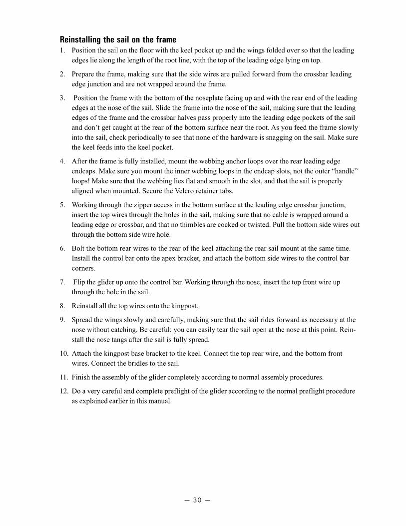
Reinstalling the sail on the frame1. Position the sail on the floor with the keel pocket up and the wings folded over so that the leading
edges lie along the length of the root line, with the top of the leading edge lying on top.
2. Prepare the frame, making sure that the side wires are pulled forward from the crossbar leadingedge junction and are not wrapped around the frame.
3. Position the frame with the bottom of the noseplate facing up and with the rear end of the leadingedges at the nose of the sail. Slide the frame into the nose of the sail, making sure that the leadingedges of the frame and the crossbar halves pass properly into the leading edge pockets of the sailand don’t get caught at the rear of the bottom surface near the root. As you feed the frame slowlyinto the sail, check periodically to see that none of the hardware is snagging on the sail. Make surethe keel feeds into the keel pocket.
4. After the frame is fully installed, mount the webbing anchor loops over the rear leading edgeendcaps. Make sure you mount the inner webbing loops in the endcap slots, not the outer “handle”loops! Make sure that the webbing lies flat and smooth in the slot, and that the sail is properlyaligned when mounted. Secure the Velcro retainer tabs.
5. Working through the zipper access in the bottom surface at the leading edge crossbar junction,insert the top wires through the holes in the sail, making sure that no cable is wrapped around aleading edge or crossbar, and that no thimbles are cocked or twisted. Pull the bottom side wires outthrough the bottom side wire hole.
6. Bolt the bottom rear wires to the rear of the keel attaching the rear sail mount at the same time.Install the control bar onto the apex bracket, and attach the bottom side wires to the control barcorners.
7. Flip the glider up onto the control bar. Working through the nose, insert the top front wire upthrough the hole in the sail.
8. Reinstall all the top wires onto the kingpost.
9. Spread the wings slowly and carefully, making sure that the sail rides forward as necessary at thenose without catching. Be careful: you can easily tear the sail open at the nose at this point. Rein-stall the nose tangs after the sail is fully spread.
10. Attach the kingpost base bracket to the keel. Connect the top rear wire, and the bottom frontwires. Connect the bridles to the sail.
11. Finish the assembly of the glider completely according to normal assembly procedures.
12. Do a very careful and complete preflight of the glider according to the normal preflight procedureas explained earlier in this manual.
— 31 —
Tuning
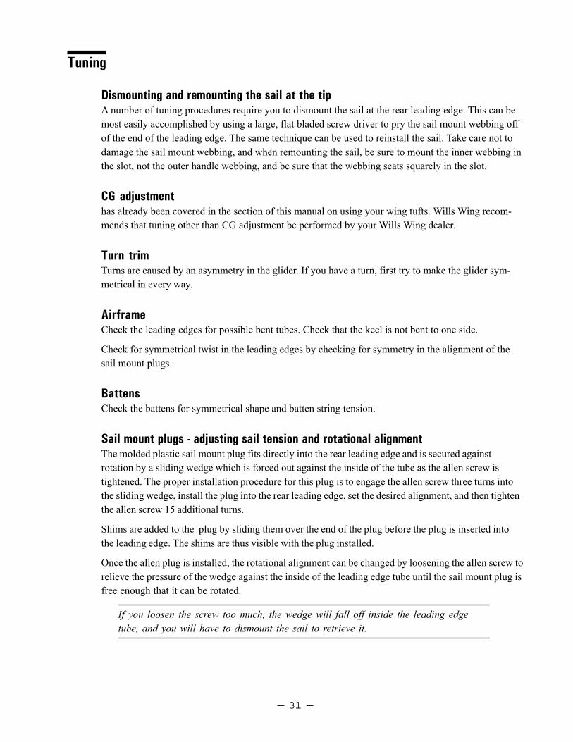
Dismounting and remounting the sail at the tipA number of tuning procedures require you to dismount the sail at the rear leading edge. This can bemost easily accomplished by using a large, flat bladed screw driver to pry the sail mount webbing offof the end of the leading edge. The same technique can be used to reinstall the sail. Take care not todamage the sail mount webbing, and when remounting the sail, be sure to mount the inner webbing inthe slot, not the outer handle webbing, and be sure that the webbing seats squarely in the slot.
CG adjustmenthas already been covered in the section of this manual on using your wing tufts. Wills Wing recom-mends that tuning other than CG adjustment be performed by your Wills Wing dealer.
Turn trimTurns are caused by an asymmetry in the glider. If you have a turn, first try to make the glider sym-metrical in every way.
AirframeCheck the leading edges for possible bent tubes. Check that the keel is not bent to one side.
Check for symmetrical twist in the leading edges by checking for symmetry in the alignment of thesail mount plugs.
BattensCheck the battens for symmetrical shape and batten string tension.
Sail mount plugs - adjusting sail tension and rotational alignmentThe molded plastic sail mount plug fits directly into the rear leading edge and is secured againstrotation by a sliding wedge which is forced out against the inside of the tube as the allen screw istightened. The proper installation procedure for this plug is to engage the allen screw three turns intothe sliding wedge, install the plug into the rear leading edge, set the desired alignment, and then tightenthe allen screw 15 additional turns.
Shims are added to the plug by sliding them over the end of the plug before the plug is inserted intothe leading edge. The shims are thus visible with the plug installed.
Once the allen plug is installed, the rotational alignment can be changed by loosening the allen screw torelieve the pressure of the wedge against the inside of the leading edge tube until the sail mount plug isfree enough that it can be rotated.
If you loosen the screw too much, the wedge will fall off inside the leading edgetube, and you will have to dismount the sail to retrieve it.

— 32 —
Sail tensionCheck for symmetrical sail tension on the leading edges. In order to check this, sight the hem of thesail at the bottom of the leading edge tube relative to the noseplate on each side. Sail tension is ad-justed by adding or removing shims in 1/8" or 1/4" increments to or from the sail mount plugs on therear ends of the leading edges. See the discussion above about how shims are added or removed.
To remove or add shims from the sail mount plug, first dismount the sail mount webbing by pulling itfree and then to the outside of the leading edge. You can use a flat bladed screwdriver to pry thewebbing off, but take care not to damage the webbing. After dismounting the sail, to remove the plug,first check and record the rotational alignment by noting the position of the scribe mark on the plugrelative to the scale on the leading edge tube. Use the allen wrench provided in your spare parts kit toloosen the allen screw until you can remove the plug. Add or remove shims as necessary, and thenreinstall the plug, making sure the alignment is correct. Fifteen turns of the allen screw after installa-tion of the plug will secure the plug in place.
Twisting a tipAfter you have made everything symmetrical, if you still have a turn, you will correct it by rotating oneor both sail mount plugs. A left turn is corrected by twisting the left sail plug clockwise (twisting thesail down at the trailing edge) or twisting the right sail plug clockwise (twisting the sail up at the trailingedge) or both. Twist counter clockwise on either or both plugs to correct a right turn.
To rotate the sail plug, use the allen wrench provided in your spare parts kit to loosen the allen screwthus pushing the wedge forward and releasing the plug.
If you loosen the screw too much, the wedge will fall off the end of the screw insidethe leading edge, and you will have to dismount the sail to retrieve it. Start byloosening the screw ten turns, and then check to see if you can rotate it. If not, loosen itone turn at a time until it can be rotated.
After rotating the plug in the desired amount in the desired direction, (see above) tighten the screw tosecure the plug against rotation. When the screw is properly tightened, there will be a slight bulge (lessthan or equal to the wall thickness of the tube) in the rear leading edge tube adjacent to the screw.
Adjusting batten tensionAll battens are tensioned by looping the batten string over the notched end of the batten twice. Theinboard batten strings should be slightly on the loose side, and the outboard batten strings should beprogressively tighter. The number one batten strings should be fairly tight, but not so tight as toslacken the sail mount webbing which mounts the sail at the tip.
Leading edge sail tensionThe tension in the leading edge of the sail, adjustable by shimming as described above, will influence theperformance and handling of the glider. If the sail is mounted too loose, the performance will deterioratenoticeably. If the sail is mounted too tight, the glider will handle poorly; it will be stiff and slow in rollresponse with excessive adverse yaw and an increased tendency to spin in a stalled turn. As the glidergets older and the sail stretches, you will need to add shims to maintain the proper tension.

— 33 —
Car Top Mounting And TransportImproper or careless transport of your glider can cause significant damage. You should transport yourglider on a rack which has at least three support points which span at least 13' of the length of theglider. These should be well padded and at least four inches wide to distribute the load. Your glidershould be mounted on your rack with the control bar facing up. It should be securely tied down withwebbing straps which are at least 1/2" wide If you drive on rough roads where the glider receivesimpact loads, you should take extra care to pad your glider internally when you pack it up. Onespecial area to pay attention to is the forward area of the glider where the crossbar center sectionbears against the top of the leading edge tubes, and the kingpost sits on top of the keel. Some extrapadding inserted in this area will save wear on your airframe and sail.
In ClosingWith proper care and maintenance, your glider will retain a high level of airworthiness for some years.Because of the relatively short history of hang gliding, and the rapid advances in new designs, we donot have a lot of information about the ultimate service life of a hang glider. We do know that ultravio-let (UV) damage to the sail from sunlight is probably the limiting factor in the life of your sail. Try toavoid exposing your sail to sunlight any time you are not actually flying it.
We also know that there are forces in nature which can be so violent that they can result in fatalaccidents regardless of the airworthiness of your aircraft. Ultimately your safety is your responsibil-ity. Know the limitations of your knowledge, skill and experience, and know the limitations of youraircraft. Fly within those limitations.
Have fun.
See you in the sky!
Wills Wing, Inc.
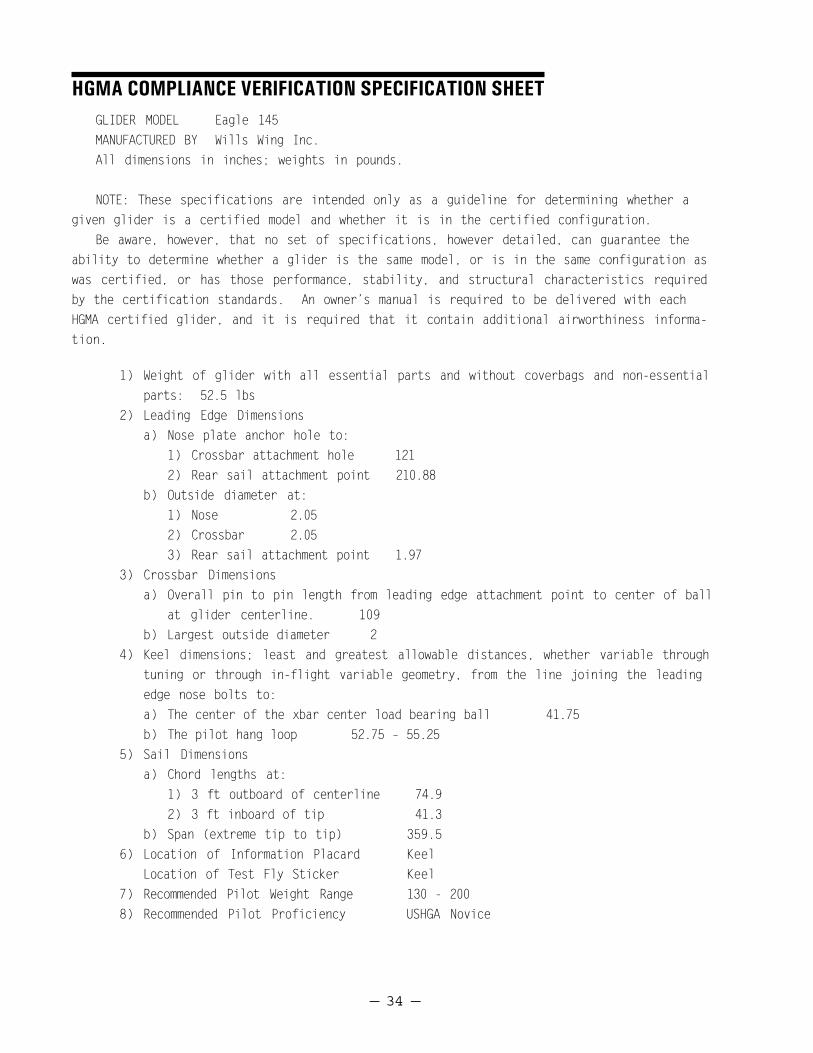
— 34 —
HGMA COMPLIANCE VERIFICATION SPECIFICATION SHEETGLIDER MODEL Eagle 145MANUFACTURED BY Wills Wing Inc.All dimensions in inches; weights in pounds.
NOTE: These specifications are intended only as a guideline for determining whether agiven glider is a certified model and whether it is in the certified configuration.
Be aware, however, that no set of specifications, however detailed, can guarantee theability to determine whether a glider is the same model, or is in the same configuration aswas certified, or has those performance, stability, and structural characteristics requiredby the certification standards. An owner’s manual is required to be delivered with eachHGMA certified glider, and it is required that it contain additional airworthiness informa-tion.
1) Weight of glider with all essential parts and without coverbags and non-essentialparts: 52.5 lbs
2) Leading Edge Dimensionsa) Nose plate anchor hole to:
1) Crossbar attachment hole 1212) Rear sail attachment point 210.88
b) Outside diameter at:1) Nose 2.052) Crossbar 2.053) Rear sail attachment point 1.97
3) Crossbar Dimensionsa) Overall pin to pin length from leading edge attachment point to center of ball
at glider centerline. 109b) Largest outside diameter 2
4) Keel dimensions; least and greatest allowable distances, whether variable throughtuning or through in-flight variable geometry, from the line joining the leadingedge nose bolts to:a) The center of the xbar center load bearing ball 41.75b) The pilot hang loop 52.75 – 55.25
5) Sail Dimensionsa) Chord lengths at:
1) 3 ft outboard of centerline 74.92) 3 ft inboard of tip 41.3
b) Span (extreme tip to tip) 359.56) Location of Information Placard Keel
Location of Test Fly Sticker Keel7) Recommended Pilot Weight Range 130 - 2008) Recommended Pilot Proficiency USHGA Novice

— 35 —
HGMA COMPLIANCE VERIFICATION SPECIFICATION SHEETGLIDER MODEL Eagle 164MANUFACTURED BY Wills Wing Inc.All dimensions in inches; weights in pounds.
NOTE: These specifications are intended only as a guideline for determining whether agiven glider is a certified model and whether it is in the certified configuration.
Be aware, however, that no set of specifications, however detailed, can guarantee theability to determine whether a glider is the same model, or is in the same configuration aswas certified, or has those performance, stability, and structural characteristics requiredby the certification standards. An owner’s manual is required to be delivered with eachHGMA certified glider, and it is required that it contain additional airworthiness informa-tion.
1) Weight of glider with all essential parts and without coverbags and non-essentialparts: 59 lbs
2) Leading Edge Dimensionsa) Nose plate anchor hole to:
1) Crossbar attachment hole 1282) Rear sail attachment point 217.75
b) Outside diameter at:1) Nose 2.052) Crossbar 2.053) Rear sail attachment point 1.97
3) Crossbar Dimensionsa) Overall pin to pin length from leading edge attachment point to center of ball
at glider centerline. 115.88b) Largest outside diameter 2.25
4) Keel dimensions; least and greatest allowable distances, whether variable throughtuning or through in-flight variable geometry, from the line joining the leadingedge nose bolts to:a) The center of the xbar center load bearing ball 43.0b) The pilot hang loop 54.5 – 57.0
5) Sail Dimensionsa) Chord lengths at:
1) 3 ft outboard of centerline 792) 3 ft inboard of tip 41
b) Span (extreme tip to tip) 3806) Location of Information Placard Keel
Location of Test Fly Sticker Keel7) Recommended Pilot Weight Range 150 - 2508) Recommended Pilot Proficiency USHGA Novice

— 36 —
HGMA COMPLIANCE VERIFICATION SPECIFICATION SHEETGLIDER MODEL Eagle 180MANUFACTURED BY Wills Wing Inc.All dimensions in inches; weights in pounds.
NOTE: These specifications are intended only as a guideline for determining whether agiven glider is a certified model and whether it is in the certified configuration.
Be aware, however, that no set of specifications, however detailed, can guarantee theability to determine whether a glider is the same model, or is in the same configuration aswas certified, or has those performance, stability, and structural characteristics requiredby the certification standards. An owner’s manual is required to be delivered with eachHGMA certified glider, and it is required that it contain additional airworthiness informa-tion.
1) Weight of glider with all essential parts and without coverbags and non-essentialparts: 62.5 lbs
2) Leading Edge Dimensionsa) Nose plate anchor hole to:
1) Crossbar attachment hole 1332) Rear sail attachment point 227.88
b) Outside diameter at:1) Nose 2.052) Crossbar 2.053) Rear sail attachment point 1.97
3) Crossbar Dimensionsa) Overall pin to pin length from leading edge attachment point to center of ball
at glider centerline. 120.38b) Largest outside diameter 2.25
4) Keel dimensions; least and greatest allowable distances, whether variable throughtuning or through in-flight variable geometry, from the line joining the leadingedge nose bolts to:a) The center of the xbar center load bearing ball 42.75b) The pilot hang loop 57.75 – 60.25
5) Sail Dimensionsa) Chord lengths at:
1) 3 ft outboard of centerline 84.62) 3 ft inboard of tip 43.1
b) Span (extreme tip to tip) 399.56) Location of Information Placard Keel
Location of Test Fly Sticker Keel7) Recommended Pilot Weight Range 175 - 2758) Recommended Pilot Proficiency USHGA Novice

Page IEagle Round Control Bar

Page IIEagle Streamline Control Bar
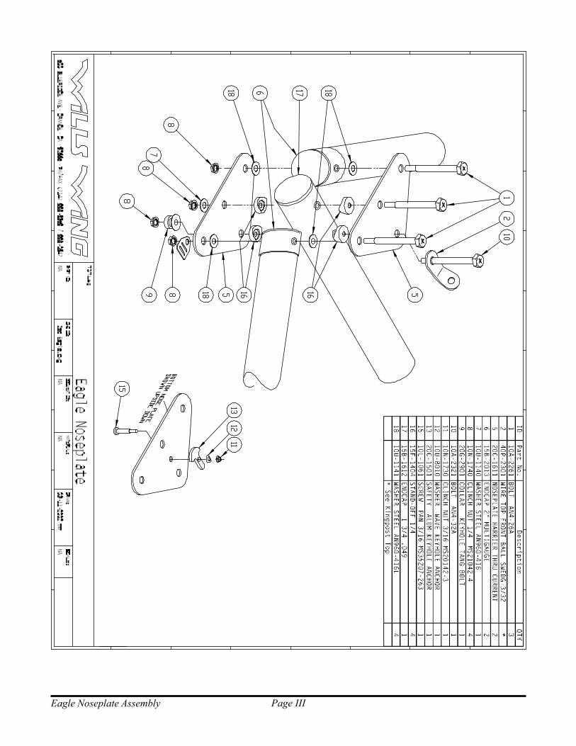
Page IIIEagle Noseplate Assembly

Page IVEagle Rear Keel

Page VEagle Kingpost Assembly
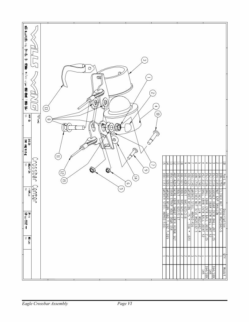
Page VIEagle Crossbar Assembly
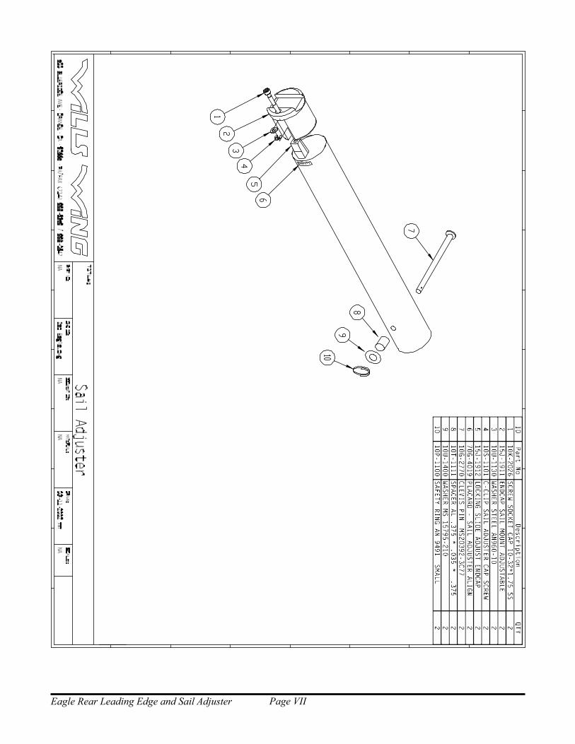
Page VIIEagle Rear Leading Edge and Sail Adjuster

Page VIIIEagle Kingpost Base and CG Track

Page IXEagle Xbar - Leading Edge Junction

Page XEagle 145 Frame Plans
1.00
2.00
50.75
55.50
58.50
94.50
135.00
.75
18.25
5
6.00 12.00 6.001.63 1.25
3.00
4.75
3.00
2 3 4
2x .38 Bushed
2x .38 Bottom .19 Thru
.25
.38 Bushed
Stabilizer
2x .50 Bushed .400
ITEM NO.QTY. PART NO. DESCRIPTION
2 1 Eagle 164 Keel front slv 44mm x 0.9mm 7075-T6
3 1 Eagle 164 Keel middle slv 44mm x 0.9mm 7075-T6
4 1 Eagle 164 Keel rear slv 44mm x 0.9mm 7075-T6
5 1 Eagle 145 Keel tube 42mm x 0.9mm 7075-T6
500 BLUERIDGE AVE ORANGE, CA 92865 PH/FAX (714) 998-6359 / 998-0647
PART NO:TITLE:
SLDDWF ID:
± .015
± 1/2± .0005± .003
DRAWN:.XXX
ANGLES.XXXX
.XXT.U.S. ± .05.X
Eagle 145 Airframe NA
STATUS:
Released
BY:
Eagle 145 KeelREVISED:
NA
2.875 lb
MATERIAL:
01-22-02
40B-1201
REVISION:
A
PEARSON
.75
1.50
.25 .19 Front View
ITEM NO. QTY. PART NO. DESCRIPTION
3 1 Eagle 145 Crossbar tube 2.00in x .049in 6061-T6
4 1 Eagle 145 Crossbar slv 1.88in x .049in 6061-T6
6.004
107.50
106.88
3.00
.38 Bushed
.25 Bottom only
Bottom View3
500 BLUERIDGE AVE ORANGE, CA 92865 PH/FAX (714) 998-6359 / 998-0647
PART NO:TITLE:
SLDDWF ID:
± .015
± 1/2± .0005± .003
DRAWN:.XXX
ANGLES.XXXX
.XXT.U.S. ± .05.X
Eagle 145 Airframe NA
STATUS:
Released
BY:
Eagle 145 CrossbarREVISED:
NA
3.394 lb
MATERIAL:
01-22-02
40D-2100
REVISION:
A
PEARSON
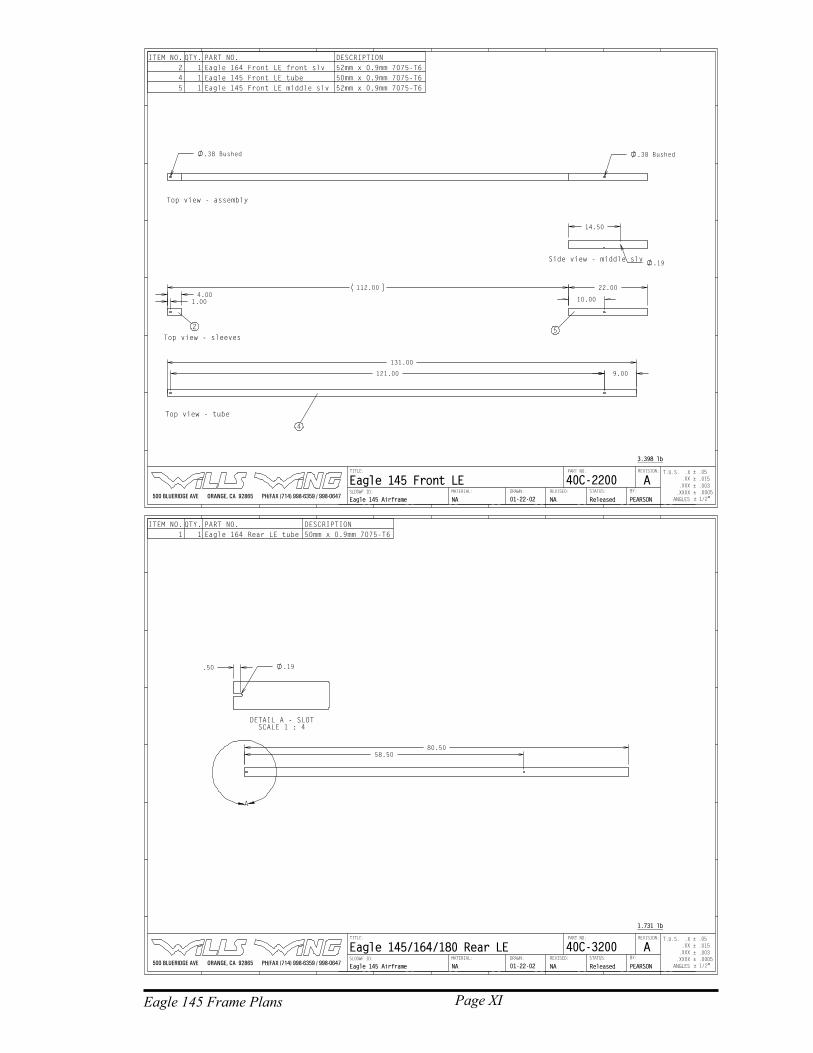
Page XIEagle 145 Frame Plans
131.00
9.00121.00
4
4.00
22.00
10.00
112.00
1.00
25
14.50
.19Side view - middle slv
Top view - sleeves
.38 Bushed .38 Bushed
Top view - tube
Top view - assembly
ITEM NO. QTY. PART NO. DESCRIPTION
2 1 Eagle 164 Front LE front slv 52mm x 0.9mm 7075-T6
4 1 Eagle 145 Front LE tube 50mm x 0.9mm 7075-T6
5 1 Eagle 145 Front LE middle slv 52mm x 0.9mm 7075-T6
500 BLUERIDGE AVE ORANGE, CA 92865 PH/FAX (714) 998-6359 / 998-0647
PART NO:TITLE:
SLDDWF ID:
± .015
± 1/2± .0005± .003
DRAWN:.XXX
ANGLES.XXXX
.XXT.U.S. ± .05.X
Eagle 145 Airframe NA
STATUS:
Released
BY:
Eagle 145 Front LEREVISED:
NA
3.398 lb
MATERIAL:
01-22-02
40C-2200
REVISION:
A
PEARSON
80.50
58.50
A
ITEM NO. QTY. PART NO. DESCRIPTION
1 1 Eagle 164 Rear LE tube 50mm x 0.9mm 7075-T6
.50 .19
DETAIL A - SLOT
SCALE 1 : 4
500 BLUERIDGE AVE ORANGE, CA 92865 PH/FAX (714) 998-6359 / 998-0647
PART NO:TITLE:
SLDDWF ID:
± .015
± 1/2± .0005± .003
DRAWN:.XXX
ANGLES.XXXX
.XXT.U.S. ± .05.X
Eagle 145 Airframe NA
STATUS:
Released
BY:
Eagle 145/164/180 Rear LEREVISED:
NA
1.731 lb
MATERIAL:
01-22-02
40C-3200
REVISION:
A
PEARSON

Page XIIEagle 164 Frame Plans
1.00
2.00
53.25
58.00
61.00
94.50
135.00
.75
18.25
1
6.00 12.00 6.001.63 1.25
3.00
4.75
3.00
2 3 4
2x .38 Bushed
2x .38 Bottom .19 Thru
.25
.38 Bushed
Stabilizer
2x .50 Bushed .400
ITEM NO.QTY. PART NO. DESCRIPTION
1 1 Eagle 164 Keel tube 42mm x 0.9mm 7075-T6
2 1 Eagle 164 Keel front slv 44mm x 0.9mm 7075-T6
3 1 Eagle 164 Keel middle slv 44mm x 0.9mm 7075-T6
4 1 Eagle 164 Keel rear slv 44mm x 0.9mm 7075-T6
500 BLUERIDGE AVE ORANGE, CA 92865 PH/FAX (714) 998-6359 / 998-0647
PART NO:TITLE:
SLDDWF ID:
± .015
± 1/2± .0005± .003
DRAWN:.XXX
ANGLES.XXXX
.XXT.U.S. ± .05.X
Eagle Airframe 1-22-02
STATUS:
Released
BY:
Eagle 164 KeelREVISED:
NA
2.875 lb
MATERIAL:
NA
40B-1201
REVISION:
A
PEARSON
.75
1.50
.25 .19 Front View
ITEM NO. QTY. PART NO. DESCRIPTION
1 1 Eagle 164 Crossbar tube 2.25in x .049in 6061-T6
2 1 Eagle 164 Crossbar slv 2.25in x .049in 6061-T6 split internal sleeve
6.002
114.00
113.38
3.00
.38 Bushed
.25 Bottom only
Bottom View1
500 BLUERIDGE AVE ORANGE, CA 92865 PH/FAX (714) 998-6359 / 998-0647
PART NO:TITLE:
SLDDWF ID:
± .015
± 1/2± .0005± .003
DRAWN:.XXX
ANGLES.XXXX
.XXT.U.S. ± .05.X
Eagle Airframe NA
STATUS:
Released
BY:
Eagle 164 XbarREVISED:
NA
4.051 lb
MATERIAL:
01-22-02
40D-2100
REVISION:
A
PEARSON

Page XIIIEagle 164 Frame Plans
138.00
9.00128.00
1
4.00
32.00
15.00
114.00
1.00
23
24.50
.19Side view - middle slv
Top view - sleeves
.38 Bushed .38 Bushed
Top view - tube
Top view - assembly
ITEM NO. QTY. PART NO. DESCRIPTION
1 1 Eagle 164 Front LE tube 50mm x 0.9mm 7075-T6
2 1 Eagle 164 Front LE front slv 52mm x 0.9mm 7075-T6
3 1 Eagle 164 Front LE middle slv 52mm x 0.9mm 7075-T6
500 BLUERIDGE AVE ORANGE, CA 92865 PH/FAX (714) 998-6359 / 998-0647
PART NO:TITLE:
SLDDWF ID:
± .015
± 1/2± .0005± .003
DRAWN:.XXX
ANGLES.XXXX
.XXT.U.S. ± .05.X
Eagle Airframe NA
STATUS:
Released
BY:
Eagle 164 Front LEREVISED:
NA
3.772 lb
MATERIAL:
01-22-02
40C-2200
REVISION:
A
PEARSON
80.50
58.50
A
ITEM NO. QTY. PART NO. DESCRIPTION
1 1 Eagle 164 Rear LE tube 50mm x 0.9mm 7075-T6
.50 .19
DETAIL A - SLOT
SCALE 1 : 4
500 BLUERIDGE AVE ORANGE, CA 92865 PH/FAX (714) 998-6359 / 998-0647
PART NO:TITLE:
SLDDWF ID:
± .015
± 1/2± .0005± .003
DRAWN:.XXX
ANGLES.XXXX
.XXT.U.S. ± .05.X
Eagle Airframe NA
STATUS:
Released
BY:
Eagle 145/164/180 Rear LEREVISED:
NA
1.731 lb
MATERIAL:
01-22-02
40C-3200
REVISION:
A
PEARSON
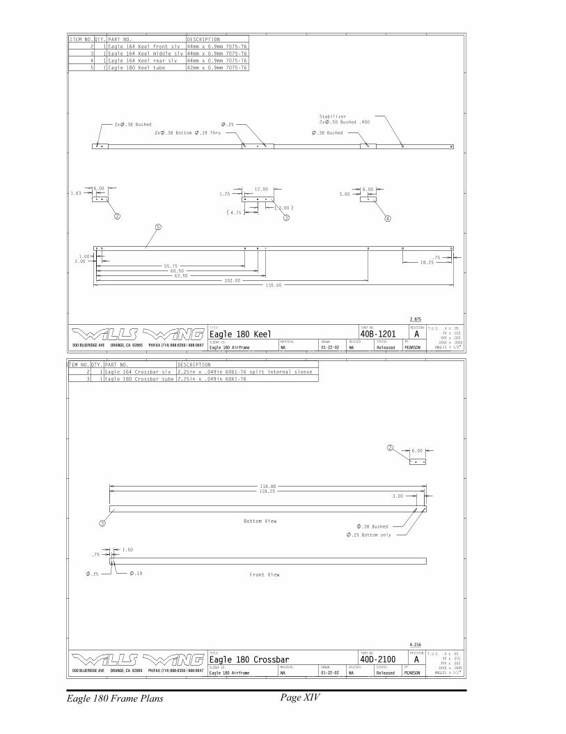
Page XIVEagle 180 Frame Plans
1.00
2.00
55.75
60.50
63.50
102.00
135.00
.75
18.25
5
6.00 12.00 6.001.63 1.25
3.00
4.75
3.00
2 3 4
2x .38 Bushed
2x .38 Bottom .19 Thru
.25
.38 Bushed
Stabilizer
2x .50 Bushed .400
ITEM NO.QTY. PART NO. DESCRIPTION
2 1 Eagle 164 Keel front slv 44mm x 0.9mm 7075-T6
3 1 Eagle 164 Keel middle slv 44mm x 0.9mm 7075-T6
4 1 Eagle 164 Keel rear slv 44mm x 0.9mm 7075-T6
5 1 Eagle 180 Keel tube 42mm x 0.9mm 7075-T6
500 BLUERIDGE AVE ORANGE, CA 92865 PH/FAX (714) 998-6359 / 998-0647
PART NO:TITLE:
SLDDWF ID:
± .015
± 1/2± .0005± .003
DRAWN:.XXX
ANGLES.XXXX
.XXT.U.S. ± .05.X
Eagle 180 Airframe NA
STATUS:
Released
BY:
Eagle 180 KeelREVISED:
NA
2.875
MATERIAL:
01-22-02
40B-1201
REVISION:
A
PEARSON
.75
1.50
.25 .19 Front View
ITEM NO. QTY. PART NO. DESCRIPTION
2 1 Eagle 164 Crossbar slv 2.25in x .049in 6061-T6 split internal sleeve
3 1 Eagle 180 Crossbar tube 2.25in x .049in 6061-T6
6.002
118.88
118.25
3.00
.38 Bushed
.25 Bottom only
Bottom View3
500 BLUERIDGE AVE ORANGE, CA 92865 PH/FAX (714) 998-6359 / 998-0647
PART NO:TITLE:
SLDDWF ID:
± .015
± 1/2± .0005± .003
DRAWN:.XXX
ANGLES.XXXX
.XXT.U.S. ± .05.X
Eagle 180 Airframe NA
STATUS:
Released
BY:
Eagle 180 CrossbarREVISED:
NA
4.216
MATERIAL:
01-22-02
40D-2100
REVISION:
A
PEARSON

Page XVEagle 180 Frame Plans
148.00
14.00133.00
4
4.00
42.00
20.00
114.00
1.00
25
34.50
.19
Side view - middle slv
Top view - sleeves
.38 Bushed .38 Bushed
Top view - tube
Top view - assembly
ITEM NO. QTY. PART NO. DESCRIPTION
2 1 Eagle 164 Front LE front slv 52mm x 0.9mm 7075-T6
4 1 Eagle 180 Front LE tube 50mm x 0.9mm 7075-T6
5 1 Eagle 180 Front LE middle slv 52mm x 0.9mm 7075-T6
500 BLUERIDGE AVE ORANGE, CA 92865 PH/FAX (714) 998-6359 / 998-0647
PART NO:TITLE:
SLDDWF ID:
± .015
± 1/2± .0005± .003
DRAWN:.XXX
ANGLES.XXXX
.XXT.U.S. ± .05.X
Eagle 180 Airframe NA
STATUS:
Released
BY:
Eagle 180 Front LEREVISED:
NA
0.000 lb
MATERIAL:
01-22-02
40C-2202
REVISION:
A
PEARSON
80.50
58.50
A
ITEM NO. QTY. PART NO. DESCRIPTION
1 1 Eagle 164 Rear LE tube 50mm x 0.9mm 7075-T6
.50 .19
DETAIL A - SLOT
SCALE 1 : 4
500 BLUERIDGE AVE ORANGE, CA 92865 PH/FAX (714) 998-6359 / 998-0647
PART NO:TITLE:
SLDDWF ID:
± .015
± 1/2± .0005± .003
DRAWN:.XXX
ANGLES.XXXX
.XXT.U.S. ± .05.X
Eagle 180 Airframe NA
STATUS:
Released
BY:
Eagle 145/164/180 Rear LEREVISED:
NA
1.731 lb
MATERIAL:
01-22-02
40C-3200
REVISION:
A
PEARSON