Precut ERCP, Fistulotomy, Papillotomy, Transpancreatic sphincterotomy. Miguel Chavez Rossell

Is the joist straight or crowned?
Mark the direction of the crown
Precut piecesfor framingfloor openings
A crew member sights each joist to de-termine the direction of the crown (pho-to left). An arrow is then drawn on theboard to indicate the top edge of theboard (photo above).Using measurements written on the sillsduring layout, kits containing all theframing members for floor openingssuch as stairs or chimneys are cut andlabeled ahead of time (photo right).

If you do the layout
carefully and precut
all the joists, the floor
will go together
quickly like a giant
jigsaw puzzle
by Rick Arnold and Mike Guertin
W e've finished backfilling the foundation, andthe mudsills are level and square. Now the realfun begins: saws screaming, hammers humming,sawdust flying. But as anxious as we are to shiftinto high-gear production mode, we always ap-proach the task of floor framing methodically andthoughtfully. With this strategy, everything goes to-gether right the first time, and the reciprocatingsaw and the cat's paw stay in the toolbox wherethey belong.
A good framing plan streamlines layout andinstallation—Before we even think about gettingour tools out, and usually before breaking ground,we start our floor on paper with a framing plan(drawing p. 54). Most of the house plans we workfrom do not include a framing layout, so usuallywe create our own.
First, we choose the best starting point for thejoist layout to minimize the number of joists andthe subfloor waste. After looking at how the houseis laid out (where the jogs are; how the roof trusseswill be laid out; where bearing walls are; wheretoilets, tubs and showers fall), we decide where tobegin the layout. With the house featured in this
article, the natural starting point was the front leftcorner because of the two adjoining sectionswhere the joists changed direction. When indoubt, we usually pick the 90° corner that has thelongest uninterrupted legs. All smaller sectionsare then blended into the larger layout.
On our plans we draw lines for each joist, head-er, in-floor beam and any special framing detailsfor the house. By using a different colored pencilfor each joist length, we can use the plan for ac-curate material ordering later. When materials aredelivered, the joist plan also enables us to directthe different-length 2xs to the appropriate areasof the floor with just a glance.
We try to have a preliminary meeting (or at leasta couple of quick faxes) with the plumber andheating contractor to identify any joists that mightpose a problem with their systems. We can alsoalert each contractor if we see that both of themexpect to fill the same joist bay. By moving a joist acouple of inches to one side or to the other, wesometimes can resolve competition for space. Wegenerally try to avoid having a joist positioned di-rectly below a wall above, and knowing which in-terior walls will contain vents, drains or ductwork
keeps us from placing a joist where it might haveto be cut.
The big exception to that rule is where the househas bearing walls running parallel to the floorjoists. In those cases we usually double or triplejoists under the bearing wall to carry the weight.However, if a plumber or HVAC sub plans to use abearing wall for drains or ducts, we identify theexact location of the wall on our plan and placethe joists under the outside the edges of the wall.Solid blocking is then installed between the joistsevery 2 ft. or so, leaving space for the systems tocome through. We also double the joists beneathlarge tubs or whirlpools if the fixture is to sit in themiddle of the joist span.
Floor details are spelled out in the layout—Once the foundation is poured and backfilled, wetake great care installing and adjusting mudsills(FHB #97, pp. 46-51), carrying beams and base-ment bearing walls. As we prepare for the floor,everything is kept level and square, and the di-mensions on the plans are matched exactly. Thecloser that we keep the tolerances at the floor-deck stage, the quicker and easier the rest of the

Assembling the floor frameThe best floor layout begins on paper. Before any lumber isordered, a detailed framing plan should be drawn. The framing plan exposespotential problem areas such as bearing walls, plumbing or floor openingsthat might require special attention, and the color code (inset) indicates joistlengths for ordering and then precutting lumber when it arrives.
String keeps the layout uniform. The bluestring in the foreground was stretched between thelayout marks on the sills. Measurements on the car-rying beams are then taken from that line.
house framing will proceed. Before beginningour layout, we string the carrying beams andbearing walls and brace them to keep themstraight. These strings are left in place so that wecan double-check the walls again after the joistsare installed.
To ensure consistency, one crew memberdoes all the joist layout. We begin our layout bymarking any special features of the floor deckthat interrupt common joist layout. In additionto the chimney and stair openings, the projectfeatured in this article had a cantilevered sec-tion, in-floor beams and two areas where thejoists change direction. These special details and measurements are
marked with a lumber crayon on the sill platesto alert the crew that the standard layout haschanged. Someone following the layout personcan then precut the odd pieces, and the instal-lation is easy and obvious. By the way, if anopening in the floor happens to cross a carry-ing beam, we snap lines across the beam fromthe marks on the opposite sill plates to keep ourmeasurements consistent.
Make sure the "X" is on the right side ofline—With all the special features of the decklaid out, the next step is laying out the commonjoists on the sill plates that run perpendicular tothe joists. This floor called for 2x10 floor joistslaid out on 16-in. centers.
Starting from the end we determined on ourplan, we make marks in. shy of each 16-in.symbol on the measuring tape. When the entiresill plate or beam is marked off, we go back andmake a square line at each mark and draw an Xforward of each line. The same procedure is re-peated on the opposite side of the house startingat the same end.
Next, we run a line between our starting markson the sill plates across any intermediate bear-ing walls or beams. This line gives us a referencepoint from which to lay out the tops of the bear-ing walls or the carrying beams (photo above).The uniform starting point helps to keep thejoists in a straight line and makes it easy to laydown the subflooring later. Walls and beams arethen measured and marked at 16-in. intervalsfrom that point.
The main body of the floor featured in this ar-ticle is 44 ft. deep. The span is broken into two14-ft. sections and one 16-ft. section. The joists inthe front section will be set ahead of our marksas indicated by the Xs. The middle section willbe set behind the mark, and the rear section willbe set ahead of the mark like the front. The twooutside sill plates get only one line to indicatethe location for each joist. But on the two inter-nal beams where joists from adjoining sectionswill overlap, we add additional lines indicatingthe outside edges of the joists. (Because we toe-nail the overlapping joists to the beam after bothjoists are in place, a single layout line would behidden beneath the joists.)
Careful attention is paid to crowns—Whileone crew member works on the layout, anothersorts and crowns the joist stock (photo bottomleft, p. 52). We use only kiln-dried lumber forfloor joists. Kiln-dried lumber is less likely thangreen lumber to shrink or to change shape overtime. And because kiln-dried lumber ispreshrunk, we don't get problems usually asso-
Rim joistgoes on first.Before anycommon joistsare installed, arim joist orband joist isnailed to theouter edge ofthe mudsills.While onecrew memberassembles therim, anothertransfers thelayout up fromthe sills to theinside face ofthe rim joist.
Taking the crown out of a rim joist. If arim joist has a severe crown, a relief cut ismade that allows the joist to be drawn all theway down to the sill or plate.
Rolling the joists into place. After the joists are laid in flat, a crewmember rolls them onto their layout marks and nails them to the rim.

Floor frame (continued)
Squash blocks carry loads fromabove. Two-by blocks called squash blockscut slightly longer than the height of thejoist help to transfer loads directly to thesill plate or carrying beam. Here, thesquash blocks are installed under header-bearing jacks for a sliding door above.
Tweaking the rim joist. Before the sheathing goes on, a string is run along the top edge ofall the rims that run perpendicular to the joists. The rim is tapped in or out and checked witha square until it is perfectly straight.
dated with green stock, such as drywall cracks,cracked tile, and doors and windows that bind.
Every piece of sawn dimensional lumber has acrown, or a natural curve it takes on after it is cutfrom a log. We look at each floor joist and markthe direction of its crown with an arrow (photobottom center, p. 52). Those with excessivecrowns (more than ¼ in. in 8 ft.) are set asideto be cut into window or door headers later.
When we get a unit of joist stock that has manyboards with crowns of more than ¼ in., we gradeeach joist with an A, B or C designation. Withoutthis extra effort, we could end up with large dif-ferences between adjacent joists, creating awashboard effect in the floor and making it dif-ficult to install the tongue-and-groove sheathing.In those cases, the straightest A-joists are used asrim joists and beneath tiled areas such askitchens and baths. Floor sections that will becovered with hardwood receive B-joists, and C-joists with the biggest crowns are saved for floorareas under carpet or to be cut into headers.
The rim is installed first—The rim joist orband joist is toenailed to the outer perimeter ofthe floor on top of the sill plates or to the topplates of exterior walls (top photo, p. 55). Weuse 16d nails every 12 in. The rim joists that runperpendicular to the layout prevent the floorjoists from rotating. Rim joists that run parallel tothe layout close off the floor area along its out-side edge. We also install band joists at the inte-rior transition points where joists change direc-tion. Here, they serve as a break point for theedges of the sheathing as well.
We select straight stock for the rim joists so thatthe crowns don't leave a space between the rimand the plate. If such a space is left, the rim willeventually settle under the weight of the houseand cause problems later. When straight stock isscarce, we make a sawcut near the middle ofthe rim joist about two-thirds of the way acrossthe board (photo bottom left, p. 55). The cut ismade in the direction of the crown and lets usfasten the joist down all the way to the plate.
We use the rim joists as in-floor headers overwindow and door openings in framed wallswherever possible. In-floor headers let us skipthe traditional headers and jack studs for open-ings in exterior walls that run parallel to the joistdirection. As long as the rim doesn't break overthe opening, a single rim joist can carry the wallweight above short openings. For wider spanssuch as over a sliding door, we double up therim over the opening.
This method uses a little less lumber framing,and more important, it increases the thermal ef-ficiency of the wall. On this house we eliminated24 jack studs (or 3 ft. of solid wood in the walls)and 36 ft. of header stock. All this space cannow be insulated.
Common joists are rolled into place—Weused to take care to cut the rim-joist stock tobreak exactly on the center of a floor joist. Butbecause the structural wall sheathing extendsdown to cover and secure the joint, there isn't

Laying down the sheathing
any real benefit in doing so. We do check theend of every rim joist to make sure that it'ssquare and trim it if it's not. Square ends are es-pecially critical at the corners to maintain theexact dimensions of the floor deck. Once all therim joists are in place, we use a framing squareor a triangular rafter square to square up all thelayout lines from the sills or basement wallplates onto the inside of the rims.
The crew member who crowns the floor joistsalso checks the end that will butt against the rimjoist for square. At the same time, framing mem-bers for floor openings are cut from the mea-surements written on the sill plates and thengrouped into kits (photo bottom right, p. 52).For example, the kit for this house's chimneyconsisted of short rim-joist pieces, headers andcripple joists. When the kit is finished and eachpiece is clearly marked, it is neatly stacked out-side the foundation close to where it will be in-stalled. In areas where joists change direction,the joists have to be cut to length to fit between
two rim joists. After being cut, these joists are al-so stacked near where they will be installed.
We usually assign one crew member to as-semble and install the kits for rough floor open-ings, and the rest of the crew installs the com-mon joists. We first lay all the joists flat on the sillplates and across the carrying beams with allthe crowns facing in the same direction (topphoto, p. 52). Now we can walk along the out-side of the foundation or on top of the platerolling the joists into place and nailing them tothe rim (photo bottom right, p. 55).
If a joist is shorter in height than the rim, we liftand nail it flush with the top of the rim. We goback later and shim under all the short joists.After a joist is nailed through the rim with four orfive 16d nails, we drive three toenails throughthe joist and into the mudsill or top plate. At thispoint, however, we don't nail the joists at thebeams or bearing walls.
After all the joists are nailed in place, werecheck the strings that we set up earlier to
straighten all the interior carrying beams andwalls as well as any exterior framed walls. Whenwe're satisfied that everything is straight, wewalk the beams and nail the overlapping joiststo each other again, flushing the tops and shim-ming under short joists. The overlapping joistsare fastened to each other with four or five nailsdriven at an angle so that the nail points don'tstick out the other side. The joists are now set onthe outside lines we drew earlier and toenailedto the beams or wall plates with four nails.
According to code (CABO 502.4.1,1995), eachjoist must bear a minimum of in. where it sitson a carrying beam, and there must be a posi-tive connection at the joist laps. There are threebasic ways to make an approved connectionbetween joists that overlap. The most commonway to connect opposing joists is by overlap-ping them a minimum of 3 in. Another methodis using either a wooden block or steel connec-tor plate as a splice across the joist joint. Thethird method is letting the subfloor sheathing
A single nail keeps the joist on the layout. After the sheet has been tacked at thecorners, a tape is hooked on the joist tacked to the sheathing, and the other joists are moveduntil they fall into position. A single nail is then driven to hold the joist on the layout.
A sledgehammer snugs the sheathinginto place. A 2x block protects the groovesin the edges of the Sheathing as it is tappedinto place with a sledgehammer.
Start spreading the .glues. A generousbead of construction adhesive is spread oneach joist and on the plywood edge.
Sheathing (continued)
span across the intersection of the joists by aminimum of 3 in.
We never use solid blocking between joistsover the beams or bearing walls to transferloads. Instead, we frame all our walls so that thestuds line up directly over the joists. Whereverwe have concentrated loads falling on a joistfrom a wall above, such as jacks carrying a load-bearing header, we install squash blocks, a tech-nique we borrowed from our engineered-I-joistexperience (FHB #108, p. 53). Squash blocksare 2x blocks cut slightly longer than the heightof the joist. They are installed on end beside thejoist to help transfer loads to the sill plate or car-rying beam (photo left, p. 56). Usually, we in-stall squash blocks after the floor is sheathed,unless we can pinpoint bearing points before.Since we began using squash blocks in conven-tional floor decks, we've virtually eliminated dry-wall cracks around door and window openings.
Don't skimp on the glue for the sheath-ing—When all the joists are fastened in place,we double-check all the floor-deck dimensions
and take diagonal measurements to make surethe deck is square before we start installing thesubfloorsheathing. If the rim joists were installedwith square ends at the corners, our measure-ments are usually close. If the diagonal mea-surement is off more than in., we tweak therim in or out to make the adjustment.
Next, we run strings along all the rim joists run-ning perpendicular to joist runs. We tap the topof the rim in or out as needed and shim if nec-essary to get the rim joist perfectly straight (pho-to right, p. 56). Squaring the joist ends helps tokeep these adjustments to a minimum. Rimsrunning parallel to the joists will be straightenedlater after the sheathing is installed.
To begin sheathing the deck, we measure 4 ft.in at both ends from our starting edge, usuallythe front of the house. We snap a line and startpumping adhesive onto the joists. From therewe snap lines every in. for a glue guide foreach row of sheathing. (We use a -in. mea-surement because the tongue and the groovecost us in. for each row of sheathing.) Thesnapped line tells us where to stop the glue for
each row to keep glue off our tapes and to keepthe joists beyond the sheathing safe to step on.
The first set of sheets is set with the tongueson the rim joist so that we don't ruin them whenwe bang the sheets into place on successiverows. The first course of sheathing is nailed offcompletely with 8d ring-shank nails so that itdoesn't drift when we drive the next set of sheetsin place. We don't glue or nail the edges of thesheets along the rim joist running parallel to thejoist direction so that it can be straightened later.
Spreading glue on the joists is an often-overlooked operation. However, we take ourgluing seriously. We probably go through manymore tubes than most crews, but we believe it'sworth the extra labor and material.
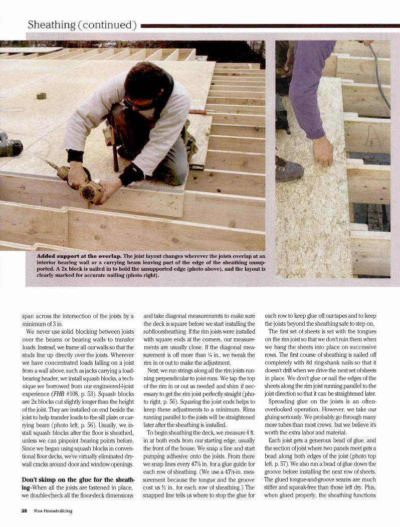
Each joist gets a generous bead of glue, andthe section of joist where two panels meet gets abead along both edges of the joist (photo topleft, p. 57). We also run a bead of glue down thegroove before installing the next row of sheets.The glued tongue-and-groove seams are muchstiffer and squeak-free than those left dry. Plus,when glued properly, the sheathing functions

as a vapor barrier, provided that all utility pene-trations are carefully sealed.
Framing crews usually just flop the sheets ofsheathing down haphazardly onto the joists andslide them over into position. In the process, theglue is smeared and rendered useless, and thejoists become a sticky, slippery mess. Instead,we try to lay each sheet down as close to whereit is supposed to go and as carefully and gentlyas possible, which keeps the glue bead where itbelongs and keeps the work area neat and safe.
As each sheet is laid down, it is tapped againstthe adjacent sheets with a 2x block and a sledge-hammer (photo bottom left, p. 57). The OSBfloor sheathing we use lies flat, and the tonguesslide easily into the grooves. When plywood isspecified, it's usually necessary to have an extracrew member stand on the seam to flatten thesheet. We adjust the joist that falls under the endof that sheet so that half or about in. of thejoist is left exposed. The outermost corner of thesheathing is then nailed to secure the joist in po-sition. After each course of sheathing is tackedin place in this manner and before the next
course is started, we hook a tape onto any ofthe secured joists and measure, adjust and nailthe rest of the joists at their proper 16-in. o.c.position with a single nail at the edge of thesheathing (photo right, p. 57).
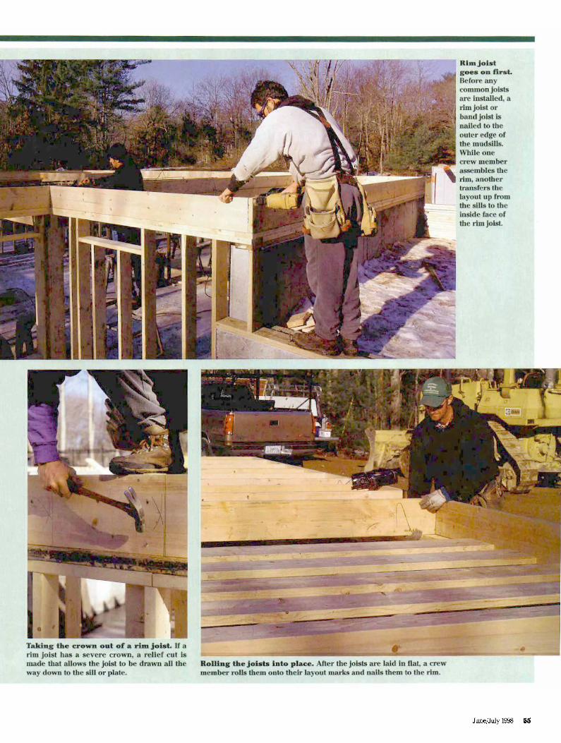
We stagger the butt joints between sheets 4 ft.with each successive course. When the layoutapproaches an area where the joists overlap, weinstall 2x blocking to support the end of thesheet as needed (photo left, facing page). Afterwe've tacked the whole field of sheets in place,we snap lines to indicate joist locations, takingcare to shift our lines where the joists overlapor change direction (photo right, facing page).One crew member then finishes all the nailingso that he can keep track of what's been nailed.
Tying up loose ends—Whenever our sheath-ing runs by an opening such as the stair chase orthe opening for the chimney, we either let asmall section of sheathing overhang or leave asmall uncovered area to begin the next sheet atthe edge of the opening. With the bulk of thefloor sheathed, we now turn to these details,trimming and filling in as needed.
Because the sheets of sheathing are in.wide, we end up with a 5-in. void at the end ofour 44-ft. house. Rather than sacrificing severalsheets of sheathing for their tongues, we cut upscrap pieces of sheathing and use them as fillers.The unsupported joint is not a concern becauseit will be covered by the 2x6 walls above.
It's rare to have a floor this wide. Most of thehouses we do are less than 30 ft. wide, so thesheathing shortfall is usually 3 in. or less. If wedon't have enough scrap sheathing to use as afiller strip, we use 1x3 strapping or rip a 1x6ledger instead, which is cheap and easy to use.
The last step is straightening the rim joists thatwere left unnailed during the sheathing opera-tion (photo above left). Measuring in in. fromthe corners at the ends of the rim, we snap a ref-erence line on top of the sheathing. We nowmove the rim joist in or out every 4 ft. or so untilthe distance from our line to the outside edge ofthe rim measures in., and we drive a nail atthat point. After the edge is tacked straight, wenail it off and trim off any excess sheathing.
The second-story floor deck is built prettymuch the same way. However, one step that wetake just before lifting the bearing walls that willsupport the next floor is laying out for the joistson top of the top plate, which is quicker thandoing the layout from staging. Once the wallsare up, we start the process of installing rimsand joists all over again.
Rick Arnold and Mike Guertin are contributingeditors to Fine Homebuilding and residential-construction consultants and builders in EastGreenwich, Rl. Photos by Roe A. Osborn.
Just say no
Here in the Northeast, whereconstruction quality is often judgedby how much wood you can packinto a house frame, omittingbridging is a controversial choice.Unless we exceed the 6:1 (depth-to-thickness) ratio in our joist material(2x12) where the CABO coderequires blocking or bridgingbetween joists, we almost neverinstall it.
To the best of our knowledge,bridging has never been proved toadd strength to a floor but it isalmost certain to add squeaks. Inthe past we tried gluing i n solidblocks, and for several years weinstalled steel bridging as analternative to blocking. We'd installthe steel bridging tighter than aguitar string only to return a yearlater and find it had loosened andwas causing squeaks. Even thoughwe use kiln-dried material, theseasonal changes in humidity causethe joists to shrink and swellenough to render any type ofbridging worthless.
We can just about guaranteesqueak-free floor in our homesunless our clients or an architectinsists on blocking or bridging. Inthose cases we are inevitablycalled back a year later to fix floorsqueaks. The remedy for thesqueaks usually involves removingany solid blocks or bridging thatdidn't have to be removed whenthe plumbers and HVAC installersdid their work.
Instead, -in; tongue-and-groove:Structural sheathing glued andnailed to the joists is effective attransferring loads to adjacent joists,which is what blocking andbridging are supposed to do. Asextra insurance, we install acontinuous 1x3 strap nailed to theunderside of the joists down theCenter of the span in basementto keep the joists from twisting. lfthe ceiling is to be finished) such asabove a living space, we install 1x3strapping 16.in. o.c. across thewhole ceiling—R. A. and M.G.
to bridging