Mark 60 Series - jordanvalve.com 60 Self-Operated preSSure regulatOrS Features & BeneFits Heavy duty...
14
Jordan Valve a division of Richards Industries 3170 Wasson Road • Cincinnati, OH 45209 513.533.5600 • 800.543.7311 • 513.871.0105 (f) [email protected] • www.jordanvalve.com Mark 60 Series Self Operated Pressure Regulators Pressure Regulators Mark 60 Pressure Regulators The Mark 60 Sliding Gate Pressure Regulator is used to regulate the downstream pressure to a predetermined setpoint. The spring in the Mark 60 holds the sliding gate seats in their normally open position to allow the process media to pass through the seats. The downstream pressure is sensed beneath the diaphragm. (A sensing line is required on sizes: 2-1/2", 3", and 4"). As the downstream pressure exceeds the setpoint, pressure is exerted on the diaphragm which raises the stem to modulate the disc (the moveable component on the sliding gate seat set) toward the closed position. As the seats close, downstream pres- sure will be reduced to the required setpoint. A decrease in pressure relaxes the spring and diaphragm to move the seats toward the open position. This brochure includes the following Series: • MK60: a line of self-operating pressure regu- lators designed with Jordan Valve's sliding gate seats • MK61: The MK61 features a larger dia- phragm than a standard MK60 to provide even greater sensitivity and minimum offset from a required setpoint • MK60QC: The MK60QC features a "Quick Change" dome for simple range spring replacements. Ideal for facilities with multiple pressure reducing applications - stock one valve with several spare springs to cover a wide range of needs • MK60H: The MK60H features a handwheel that replaces the adjusting screw for easy changes to the setpoint • MK60HP: Working pressure fully rated to ANSI Class 600 pressures, the HP options permits setpoints as high as 450 psi • MK60GP: The MK60GP option requires grain processing modification for starch cookers and other viscous services • MK601/602: The MK601 and MK602 meet higher capacity requirements than standard regulators Mark 60 Features • Sliding Gate Trim – unique seat design for unsurpassed trim life and accuracy • Jorcote Seat Coating – ceramic composite for liquids, gases and especially steam. Very low friction with outstanding wear resistance and a temperature rating of up to 550°F. Steam tested to 1,000,000 cycles and still maintained Class IV leakage. • Jorlon Diaphragm – extremely durable, virtually universally applicable up to 450°F. Tested without failure to over 1,000,000 full stroke cycles. Ideal for steam, gases and liquids. 316SST diaphragm ap- plicable up to 550°F. • Straight-through Flow – The flow is straight through the valve seats and body. Direction of the disc travel is perpendicular to the flow, not opposed to the direction of the flow. Thus, the flow does not unbalance the seats. The MK60 can use a wider range of its stroke to give ac- curate control; less offset • Quiet Operation – typically 5-10 dB less than conventional globe style regulators. The disc and plate are always in contact, which elimi- nates chattering. Straight-through flow mini- mizes turbulence. Multiple orifices in the plate and disc divide the flow stream into smaller flow components • Minimum Maintenance – The MK60 sliding gate seats require no special tools for disas- sembly. The seats are pre-lapped at the factory and are self-lapping while in operation ensuring a continual tight shutoff CRN Registration Number Available
-
Upload
nguyentruc -
Category
Documents
-
view
214 -
download
0
Transcript of Mark 60 Series - jordanvalve.com 60 Self-Operated preSSure regulatOrS Features & BeneFits Heavy duty...
Jordan Valve a division of Richards Industries 3170 Wasson Road • Cincinnati, OH 45209 513.533.5600 • 800.543.7311 • 513.871.0105 (f)[email protected] • www.jordanvalve.com
Mark 60 SeriesSelf Operated Pressure Regulators
Pressure
Re
gulato
rs
M
ark 60
Pressure
Re
gulato
rs
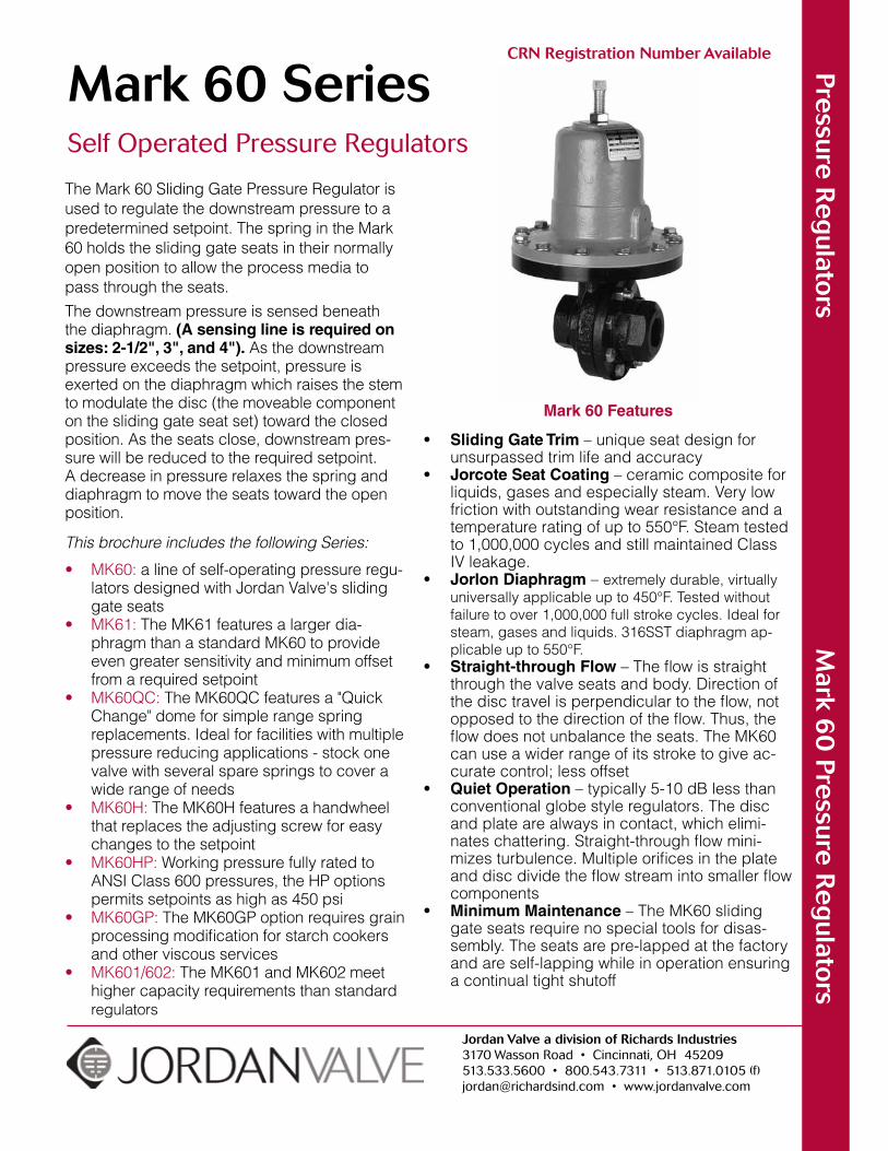
The Mark 60 Sliding Gate Pressure Regulator is used to regulate the downstream pressure to a predetermined setpoint. The spring in the Mark 60 holds the sliding gate seats in their normally open position to allow the process media to pass through the seats.The downstream pressure is sensed beneath the diaphragm. (A sensing line is required on sizes: 2-1/2", 3", and 4"). As the downstream pressure exceeds the setpoint, pressure is exerted on the diaphragm which raises the stem to modulate the disc (the moveable component on the sliding gate seat set) toward the closed position. As the seats close, downstream pres-sure will be reduced to the required setpoint. A decrease in pressure relaxes the spring and diaphragm to move the seats toward the open position.
This brochure includes the following Series:
• MK60: a line of self-operating pressure regu-lators designed with Jordan Valve's sliding gate seats
• MK61: The MK61 features a larger dia-phragm than a standard MK60 to provide even greater sensitivity and minimum offset from a required setpoint
• MK60QC: The MK60QC features a "Quick Change" dome for simple range spring replacements. Ideal for facilities with multiple pressure reducing applications - stock one valve with several spare springs to cover a wide range of needs
• MK60H: The MK60H features a handwheel that replaces the adjusting screw for easy changes to the setpoint
• MK60HP: Working pressure fully rated to ANSI Class 600 pressures, the HP options permits setpoints as high as 450 psi
• MK60GP: The MK60GP option requires grain processing modification for starch cookers and other viscous services
• MK601/602: The MK601 and MK602 meet higher capacity requirements than standard regulators
Mark 60 Features
• Sliding Gate Trim – unique seat design for unsurpassed trim life and accuracy
• Jorcote Seat Coating – ceramic composite for liquids, gases and especially steam. Very low friction with outstanding wear resistance and a temperature rating of up to 550°F. Steam tested to 1,000,000 cycles and still maintained Class IV leakage.
• Jorlon Diaphragm – extremely durable, virtually universally applicable up to 450°F. Tested without failure to over 1,000,000 full stroke cycles. Ideal for steam, gases and liquids. 316SST diaphragm ap-plicable up to 550°F.
• Straight-through Flow – The flow is straight through the valve seats and body. Direction of the disc travel is perpendicular to the flow, not opposed to the direction of the flow. Thus, the flow does not unbalance the seats. The MK60 can use a wider range of its stroke to give ac-curate control; less offset
• Quiet Operation – typically 5-10 dB less than conventional globe style regulators. The disc and plate are always in contact, which elimi-nates chattering. Straight-through flow mini-mizes turbulence. Multiple orifices in the plate and disc divide the flow stream into smaller flow components
• Minimum Maintenance – The MK60 sliding gate seats require no special tools for disas-sembly. The seats are pre-lapped at the factory and are self-lapping while in operation ensuring a continual tight shutoff
CRN Registration Number Available
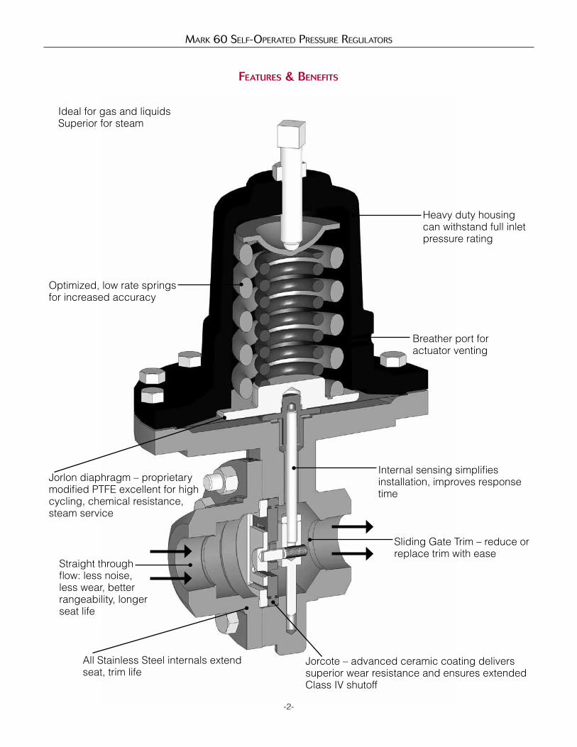
Mark 60 Self-Operated preSSure regulatOrS
Features & BeneFits
Heavy duty housing can withstand full inlet pressure rating
Breather port for actuator venting
Internal sensing simplifies installation, improves response time
Sliding Gate Trim – reduce or replace trim with ease
Jorcote – advanced ceramic coating delivers superior wear resistance and ensures extended Class IV shutoff
All Stainless Steel internals extend seat, trim life
Straight through flow: less noise, less wear, better rangeability, longer seat life
Jorlon diaphragm – proprietary modified PTFE excellent for high cycling, chemical resistance, steam service
Optimized, low rate springsfor increased accuracy
Ideal for gas and liquidsSuperior for steam
-2-
Mark 60 Self-Operated preSSure regulatOrS
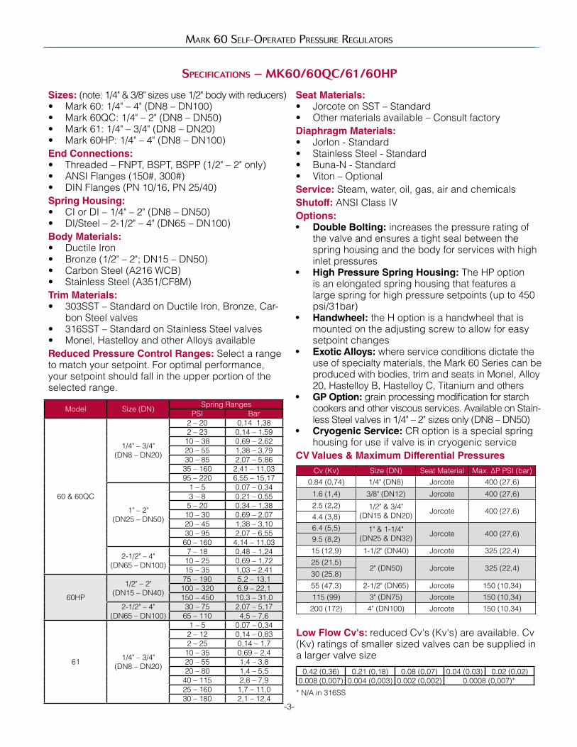
speciFications – MK60/60Qc/61/60Hp
Sizes: (note: 1/4" & 3/8" sizes use 1/2" body with reducers)• Mark 60: 1/4" – 4" (DN8 – DN100)• Mark 60QC: 1/4" – 2" (DN8 – DN50)• Mark 61: 1/4" – 3/4" (DN8 – DN20)• Mark 60HP: 1/4" – 4" (DN8 – DN100)End Connections: • Threaded – FNPT, BSPT, BSPP (1/2" – 2" only)• ANSI Flanges (150#, 300#)• DIN Flanges (PN 10/16, PN 25/40)Spring Housing: • CI or DI – 1/4" – 2" (DN8 – DN50)• DI/Steel – 2-1/2" – 4" (DN65 – DN100) Body Materials: • Ductile Iron• Bronze (1/2" – 2"; DN15 – DN50)• Carbon Steel (A216 WCB)• Stainless Steel (A351/CF8M) Trim Materials: • 303SST – Standard on Ductile Iron, Bronze, Car-
bon Steel valves• 316SST – Standard on Stainless Steel valves• Monel, Hastelloy and other Alloys availableReduced Pressure Control Ranges: Select a range to match your setpoint. For optimal performance, your setpoint should fall in the upper portion of the selected range.
-3-
Seat Materials: • Jorcote on SST – Standard• Other materials available – Consult factory Diaphragm Materials: • Jorlon - Standard• Stainless Steel - Standard• Buna-N - Standard• Viton – OptionalService: Steam, water, oil, gas, air and chemicalsShutoff: ANSI Class IVOptions: • Double Bolting: increases the pressure rating of
the valve and ensures a tight seal between the spring housing and the body for services with high inlet pressures
• High Pressure Spring Housing: The HP option is an elongated spring housing that features a large spring for high pressure setpoints (up to 450 psi/31bar)
• Handwheel: the H option is a handwheel that is mounted on the adjusting screw to allow for easy setpoint changes
• Exotic Alloys: where service conditions dictate the use of specialty materials, the Mark 60 Series can be produced with bodies, trim and seats in Monel, Alloy 20, Hastelloy B, Hastelloy C, Titanium and others
• GP Option: grain processing modification for starch cookers and other viscous services. Available on Stain-less Steel valves in 1/4" – 2" sizes only (DN8 – DN50)
• Cryogenic Service: CR option is a special spring housing for use if valve is in cryogenic service
CV Values & Maximum Differential Pressures
Model Size (DN) Spring RangesPSI Bar
60 & 60QC
1/4" – 3/4" (DN8 – DN20)
2 – 20 0,14 1,382 – 23 0,14 – 1,5910 – 38 0,69 – 2,6220 – 55 1,38 – 3,7930 – 85 2,07 – 5,8635 – 160 2,41 – 11,0395 – 220 6,55 – 15,17
1" – 2" (DN25 – DN50)
1 – 5 0,07 – 0,343 – 8 0,21 – 0,555 – 20 0,34 – 1,3810 – 30 0,69 – 2,0720 – 45 1,38 – 3,1030 – 95 2,07 – 6,5560 – 160 4,14 – 11,03
2-1/2" – 4" (DN65 – DN100)
7 – 18 0,48 – 1,2410 – 25 0,69 – 1,7215 – 35 1,03 – 2,41
60HP
1/2" – 2"(DN15 – DN40)
75 – 190 5,2 – 13,1100 – 320 6,9 – 22,1150 – 450 10,3 – 31,0
2-1/2" – 4"(DN65 – DN100)
30 – 75 2,07 – 5,1765 – 110 4,5 – 7,6
61 1/4" – 3/4"(DN8 – DN20)
1 – 5 0,07 – 0,342 – 12 0,14 – 0,832 – 25 0,14 – 1,710 – 35 0,69 – 2,420 – 55 1,4 – 3,820 – 80 1,4 – 5,540 – 115 2,8 – 7,925 – 160 1,7 – 11,030 – 180 2,1 – 12,4
Cv (Kv) Size (DN) Seat Material Max. ∆P PSI (bar)0.84 (0,74) 1/4" (DN8) Jorcote 400 (27,6)
1.6 (1,4) 3/8" (DN12) Jorcote 400 (27,6)
2.5 (2,2) 1/2" & 3/4" (DN15 & DN20) Jorcote 400 (27,6)
4.4 (3,8)6.4 (5,5) 1" & 1-1/4"
(DN25 & DN32) Jorcote 400 (27,6)9.5 (8,2)15 (12,9) 1-1/2" (DN40) Jorcote 325 (22,4)25 (21,5)
2" (DN50) Jorcote 325 (22,4)30 (25,8)
55 (47,3) 2-1/2" (DN65) Jorcote 150 (10,34)115 (99) 3" (DN75) Jorcote 150 (10,34)
200 (172) 4" (DN100) Jorcote 150 (10,34)
Low Flow Cv's: reduced Cv's (Kv's) are available. Cv (Kv) ratings of smaller sized valves can be supplied in a larger valve size
0.42 (0,36) 0.21 (0,18) 0.08 (0,07) 0.04 (0,03) 0.02 (0,02)0.008 (0,007) 0.004 (0,003) 0.002 (0,002) 0.0008 (0,007)*
* N/A in 316SS

Mark 60 Self-Operated preSSure regulatOrS
MaxiMuM WorKing pressure, psi
-4-
MaxiMuM WorKing pressure, Bar
Temp °FDI Body BRZ Body
150# 300# TE 150# 300# TE
-20 to 100 250 300 [600] 300 [600] 225 300 [500] 300 [500]
200 235 300 [600] 300 [600] 215 300 [475] 300 [475]
300 215 300 [565] 300 [600] 195 300 [425] 300 [425]
400 200 300 [525] 300 [600] 170 300 [375] 300 [375]
500 170 300 [495] 300 [600] 150 300 [325] 300 [325]
600 140 300 [465] 300 [600] — — —
650 125 300 [450] 300 [600] — — —
• Mark 60 Size Range: 1/4" – 2"
Temp °FCS Body SS Body
150# 300# TE 150# 300# TE
-20 to 100 285 300 [740] 300 [950] 275 300 [720] 300 [950]
200 260 300 [675] 300 [950] 240 300 [620] 300 [950]
300 230 300 [655] 300 [950] 215 300 [560] 300 [950]
400 200 300 [635] 300 [950] 195 300 [515] 300 [950]
500 170 300 [600] 300 [950] 170 300 [480] 300 [950]
600 140 300 [550] 300 [950] 140 300 [450] 300 [900]
650 125 300 [535] 300 [950] 125 300 [445] 300 [890]
• Mark 60 Size Range: 1/4" – 2"
Temp °FDI Body CS Body SS Body
150# 300# 150# 300# 150# 300#
-20 to 100 250 500 285 500 275 500
200 235 500 260 500 240 500
300 215 500 230 500 215 500
400 200 500 200 500 195 500
500 170 495 170 500 170 500
• Mark 60 Size Range: 2-1/2" – 4"
Temp °FCS Body SS Body
600# Flange or NPT 600# Flange or NPT
100 1480 1440
200 1355 1240
300 1315 1120
400 1270 1030
500 1208 955
600 1098 905
650 1075 890
• Mark 60HP Size Range:1/2" – 2"
Temp °CDI Body BRZ Body
150# 300# TE 150# 300# TE
-29 to 38 17 21 [41] 21 [41] 16 21 [34] 21 [34]
93 16 21 [41] 21 [41] 15 21 [33] 21 [33]
149 15 21 [39] 21 [41] 13 21 [29] 21 [29]
204 14 21 [36] 21 [41] 12 21 [26] 21 [26]
260 12 21 [34] 21 [41] 10 21 [22] 21 [22]
316 10 21 [32] 21 [41] — — —
343 9 21 [31] 21 [41] — — —
• Mark 60 Size Range: DN8 – DN50
Temp °CCS Body SS Body
150# 300# TE 150# 300# TE
-29 to 38 20 21 [51] 21 [66] 19 21 [49] 21 [66]
93 18 21 [47] 21 [66] 17 21 [43] 21 [66]
149 16 21 [45] 21 [66] 15 21 [39] 21 [66]
204 14 21 [44] 21 [66] 13 21 [36] 21 [66]
260 12 21 [41] 21 [66] 12 21 [33] 21 [66]
316 10 21 [38] 21 [66] 10 21 [31] 21 [62]
343 9 21 [37] 21 [66] 9 21 [31] 21 [61]
• Mark 60 Size Range: DN8 – DN50
Temp °CDI Body CS Body SS Body
150# 300# 150# 300# 150# 300#
-29 to 38 17 34 20 34 19 34
93 16 34 18 34 17 34
149 15 34 16 34 15 34
204 14 34 14 34 13 34
260 12 34 12 34 12 34
• Mark 60 Size Range: DN65 – DN100
Temp °CCS Body SS Body
600# Flange or NPT 600# Flange or NPT
38 102 99
93 93 85
149 91 77
204 88 71
260 83 66
316 75 62
343 74 61
• Mark 60HP Size Range: DN15 – DN50
Notes:1. Double bolting option is required to reach pressures indicated in Brackets [ ].2. If weld flanges are supplied, use ratings in "TE" column or flange rating, whichever is less (i.e. ANSI 600/900 flanges or PN64/100 flanges).3. Consult factory for availability of ANSI/DIN/JIS flanges not indicated above.4. Consult factory for maximum working pressure on 2-1/2" - 4" (DN65 - DN100) Mark 60HP Series
Mark 60 Self-Operated preSSure regulatOrS
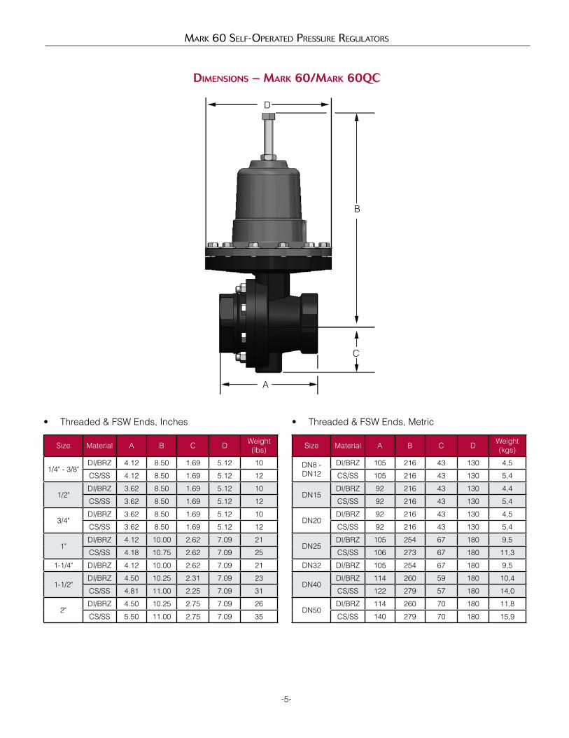
DiMensions – MarK 60/MarK 60Qc
-5-
D
B
C
A
Size Material A B C D Weight(lbs)
1/4" - 3/8"DI/BRZ 4.12 8.50 1.69 5.12 10
CS/SS 4.12 8.50 1.69 5.12 12
1/2"DI/BRZ 3.62 8.50 1.69 5.12 10
CS/SS 3.62 8.50 1.69 5.12 12
3/4"DI/BRZ 3.62 8.50 1.69 5.12 10
CS/SS 3.62 8.50 1.69 5.12 12
1"DI/BRZ 4.12 10.00 2.62 7.09 21
CS/SS 4.18 10.75 2.62 7.09 25
1-1/4" DI/BRZ 4.12 10.00 2.62 7.09 21
1-1/2"DI/BRZ 4.50 10.25 2.31 7.09 23
CS/SS 4.81 11.00 2.25 7.09 31
2"DI/BRZ 4.50 10.25 2.75 7.09 26
CS/SS 5.50 11.00 2.75 7.09 35
• Threaded & FSW Ends, Inches
Size Material A B C D Weight(kgs)
DN8 - DN12
DI/BRZ 105 216 43 130 4,5
CS/SS 105 216 43 130 5,4
DN15DI/BRZ 92 216 43 130 4,4
CS/SS 92 216 43 130 5,4
DN20DI/BRZ 92 216 43 130 4,5
CS/SS 92 216 43 130 5,4
DN25DI/BRZ 105 254 67 180 9,5
CS/SS 106 273 67 180 11,3
DN32 DI/BRZ 105 254 67 180 9,5
DN40DI/BRZ 114 260 59 180 10,4
CS/SS 122 279 57 180 14,0
DN50DI/BRZ 114 260 70 180 11,8
CS/SS 140 279 70 180 15,9
• Threaded & FSW Ends, Metric

Mark 60 Self-Operated preSSure regulatOrS
DiMensions – MarK 60
-6-
D
B
C
A1
Size ANSI Flange
A1 B C D Weight (lbs)
DI/BRZ CS/SS DI/BRZ CS/SS ALL ALL DI/BRZ CS/SS
1/2"150# 7.25 7.25 9.00 9.00 1.69 5.12 13 15
300# 7.50 7.50 9.00 9.00 1.69 5.12 14 16
3/4"150# 7.25 7.25 9.00 9.00 1.69 5.12 14 16
300# 7.62 7.62 9.00 9.00 1.69 5.12 16 17
1"150# 7.25 7.25 11.25 11.75 2.62 7.09 26 34
300# 8.751 7.752 11.25 11.75 2.62 7.09 28 37
1-1/4"150# 7.87 — 11.25 — 2.62 7.09 28 —
300# 8.37 — 11.25 — 2.62 7.09 31 —
1-1/2"150# 8.75 8.75 11.25 13.00 2.31 7.09 42 46
300# 10.251 9.252 11.25 13.00 2.31 7.09 45 52
2"150# 10.00 10.00 11.50 13.25 2.75 7.09 46 50
300# 10.50 10.50 11.50 13.25 2.75 7.09 49 55
Flanged End CS/SS
Larger Sizes A1 B C D Weight (lbs)
2-1/2"125-150# 10.88 18.75 6.95 12.75 165
250-300# 11.50 18.75 6.95 12.75 165
3"125-150# 11.75 18.75 6.95 12.75 185
250-300# 12.50 18.75 6.95 12.75 185
4"125-150# 13.88 18.75 8.00 12.75 215
250-300# 14.50 18.75 8.00 12.75 215
• Flanged Ends, ANSI, Inches
• Flanged Ends, Metric
SizeDN
ANSI Flange
A1 B C D Weight (kgs)
DI/BRZ 1 CS/SS DI/BRZ CS/SS ALL ALL DI/BRZ CS/SS
1510/16 184 130 229 229 43 130 5,9 6,8
25/40 184 130 229 229 43 130 6,4 7,3
2010/16 184 150 229 229 43 130 6,4 7,3
25/40 184 150 229 229 43 130 7,3 7,7
2510/16 222 160 286 298 67 180 11,8 15,4
25/40 222 160 286 298 67 180 12,7 16,8
3210/16 222 — 286 — 67 180 12,7 —
25/40 222 — 286 — 67 180 14,1 —
4010/16 222 200 286 330 59 180 19,1 20,9
25/40 222 200 286 330 59 180 20,4 23,6
5010/16 254 230 292 337 70 180 20,9 22,7
25/40 254 230 292 337 70 180 22,2 24,9
Flanged End CS/SS
Larger Sizes A1 B C D Weight (kgs)
6510/16 276 476 177 324 75
25/40 292 476 177 324 75
8010/16 298 476 177 324 84
25/40 318 476 177 324 84
10010/16 353 476 203 324 98
25/40 368 476 203 324 98
1 Not IFE and NOT per DIN3202

Mark 60 Self-Operated preSSure regulatOrS
DiMensions – MarK 60Hp
-7-
D
B
C
AA1
Size Material A B C D Weight(lbs)
1/2" - 3/4"DI/BRZ 3.62 12.75 1.75 5.12 15
CS/SS 3.62 12.75 1.75 5.12 17
1"DI/BRZ 4.12 13.00 2.12 5.20 21
CS/SS 4.18 13.25 2.12 5.20 25
1-1/4" DI/BRZ 4.12 13.00 2.12 5.20 21
1-1/2"DI/BRZ 4.50 13.25 2.31 5.20 23
CS/SS 4.81 13.75 2.50 5.20 31
2"DI/BRZ 4.50 13.25 2.50 5.20 26
CS/SS 5.50 14.00 2.50 5.20 35
• Threaded & FSW Ends, Inches
Size Material A B C D Weight(lbs)
DN15 & 20
DI/BRZ 92 324 45 130 6,8
CS/SS 92 324 45 130 7,7
DN25DI/BRZ 105 330 54 132 9,5
CS/SS 106 337 54 132 11,3
DN32 DI/BRZ 105 330 54 132 9,5
DN40DI/BRZ 114 337 59 132 10,4
CS/SS 122 349 64 132 14,1
DN50DI/BRZ 114 337 64 132 11,8
CS/SS 140 356 64 132 15,9
• Threaded & FSW Ends, Metric
Size ANSI Flange
A1 B C D Weight (lbs)
DI/BRZ CS/SS ALL ALL ALL All
1/2"
150# 7.25 7.25 12.75 1.69 5.20
21 •300# 7.50 7.50 12.75 1.69 5.20
• 600# 8.00 8.00 12.25 1.69 5.20
3/4"
150# 7.25 7.25 12.75 1.69 5.20
22 •300# 7.62 7.62 12.75 1.69 5.20
• 600# 8.12 8.12 12.25 1.69 5.20
1"
150# 7.25 7.25 13.25 2.62 5.20
37300# 7.75 7.75 13.25 2.62 5.20
• 600# 8.25 8.25 12.75 2.62 5.20
1-1/4"150# 7.87 — 12.75 2.62 5.20
37300# 8.37 — 12.75 2.62 5.20
1-1/2"
150# 8.75 8.75 13.75 2.31 5.20
45300# 9.25 9.25 13.75 2.31 5.20
• 600# 9.87 9.87 13.25 2.31 5.20
2"
150# 10.00 10.00 14.00 2.75 5.20
49300# 10.50 10.50 14.00 2.75 5.20
• 600# 11.25 11.25 13.50 2.75 5.20
• Flanged Ends, Inches
• 600# are not IFE• For IFE, add 1" to all "B" dimensions (1" – 2" sizes only)
Size ANSI Flange
A1 B2 C D Weight (kgs)
DI/BRZ1 CS/SS ALL ALL ALL All
1510/16 184 130 324 43 132
9,525/40 184 130 324 43 132
2010/16 184 150 324 43 132
1025/40 184 150 324 43 132
2510/16 184 160 337 67 132
1725/40 184 160 337 67 132
3210/16 200 — 324 67 132
1725/40 200 — 324 67 132
4010/16 222 200 349 59 132
2025/40 222 200 349 59 132
5010/16 254 230 356 70 132
2225/40 254 230 356 70 132
• Flanged Ends, Metric3
1 Not IFE and not per DIN32022 For IFE, add 25,4 mm3 For all DIN flanges, please consult factory4 Consult factory for dimensions on 2-1/2" - 4" (DN65 - DN100) Mark 60HP

Mark 60 Self-Operated preSSure regulatOrS
DiMensions – MarK 61
-8-
D
B
C
A1
Size ANSI Flange
A1 B C D Weight (lbs)
DI/BRZ CS/SS DI/BRZ CS/SS ALL ALL DI/BRZ CS/SS
1/2" & 3/4"
150# 9.62 9.62 10.25 10.25 2.25 7.12 26 26
300# 10.25 10.25 10.25 10.25 2.25 7.12 29 29
• Flanged Ends, ANSI, Inches
Size Material A B C D Weight(lbs)
1/4" - 3/8"DI/BRZ 4.12 10.25 2.25 7.12 12
CS/SS 4.12 10.25 2.25 7.12 13
1/2" - 3/4"DI/BRZ 3.62 10.25 2.25 7.12 12
CS/SS 3.62 10.25 2.25 7.12 13
• Threaded & FSW Ends, Inches
Size Material A B C D Weight(kgs)
DN8 - 10DI/BRZ 105 260 57 181 5,4
CS/SS 105 260 57 181 5,9
DN15 - 20DI/BRZ 92 260 57 181 5,4
CS/SS 92 260 57 181 5,9
• Threaded & FSW Ends, Metric Size ANSI Flange
A11 B C D Weight (kgs)
DI/BRZ CS/SS DI/BRZ CS/SS ALL ALL DI/BRZ CS/SS
DN15 & 20
10/16 244 244 260 260 57 181 12 12
25/40 260 260 260 260 57 181 13 13
• Flanged Ends, ANSI, Metric
1 Not per DIN 3202
Mark 60 Self-Operated preSSure regulatOrS
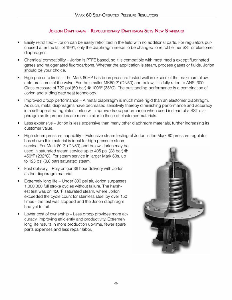
Jorlon DiapHragM - revolutionary DiapHragM sets neW stanDarD
-9-
• Easily retrofitted – Jorlon can be easily retrofitted in the field with no additional parts. For regulators pur-chased after the fall of 1991, only the diaphragm needs to be changed to retrofit either SST or elastomer diaphragms.
• Chemical compatibility – Jorlon is PTFE based, so it is compatible with most media except fluorinated gases and halogenated fluorocarbons. Whether the application is steam, process gases or fluids, Jorlon should be your choice.
• High pressure limits – The Mark 60HP has been pressure tested well in excess of the maximum allow-able pressures of the valve. For the smaller MK60 2" (DN50) and below, it is fully rated to ANSI 300 Class pressure of 720 psi (50 bar) @ 100°F (38°C). The outstanding performance is a combination of Jorlon and sliding gate seat technology.
• Improved droop performance – A metal diaphragm is much more rigid than an elastomer diaphragm. As such, metal diaphragms have decreased sensitivity thereby diminishing performance and accuracy in a self-operated regulator. Jorlon will improve droop performance when used instead of a SST dia-phragm as its properties are more similar to those of elastomer materials.
• Less expensive – Jorlon is less expensive than many other diaphragm materials, further increasing its customer value.
• High steam pressure capability – Extensive steam testing of Jorlon in the Mark 60 pressure regulator has shown this material is ideal for high pressure steam service. For Mark 60 2" (DN50) and below, Jorlon may be used in saturated steam service up to 405 psi (28 bar) @ 450°F (232°C). For steam service in larger Mark 60s, up to 125 psi (8,6 bar) saturated steam.
• Fast delivery – Rely on our 36 hour delivery with Jorlon as the diaphragm material.
• Extremely long life – Under 300 psi air, Jorlon surpasses 1,000,000 full stroke cycles without failure. The harsh-est test was on 450°F saturated steam, where Jorlon exceeded the cycle count for stainless steel by over 150 times - the test was stopped and the Jorlon diaphragm had yet to fail.
• Lower cost of ownership – Less droop provides more ac-curacy, improving efficiently and productivity. Extremely long life results in more production up-time, fewer spare parts expenses and less repair labor.
1 & 2 End Connections1/4" – 2" MK60/61
PT NPTBT BSPTBP BSPPSW FSWF1 125# IFE (Except IFE)I5 150# IFEF5 150# FE (Except IFE)F2 250#FE (Except IFE)I3 300# IFEF3 300# FE (Except IFE)
2-1/2" – 4" MK60I1 125# IFEI5 150# IFEI2 250# IFEI3 300# IFEI7 PN10 DIN IFE (CS/S6) DN15-150I6 PN16 DIN IFE (CS/S6) DN15-150I8 PN25 DIN IFE (CS/S6) DN15-150I4 PN 40 DIN IFE (CS/S6) DN15-150
Mark 60 Self-Operated preSSure regulatOrS
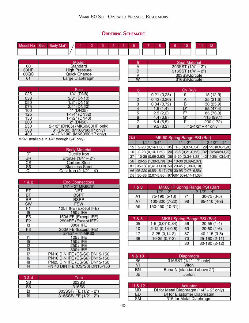
orDering scHeMatic
-10-
Model60 Standard
60HP High Pressure60QC Quick Change
61 Large Diaphragm
Size025 1/4" (DN8)038 3/8" (DN10)050 1/2" (DN15)075 3/4" (DN20)100 1" (DN25)125 1-1/4" (DN32)150 1-1/2" (DN40)200 2" (DN50)250 2-1/2" (DN65) (MK60/60HP only)300 3" (DN80) (MK60/60HP only)400 4" (DN100) (MK60/60HP only)
Model No Size Body Mat'l 1 2 3 4 5 6 7 8 9 10 11 12
MK61 available in 1/4" through 3/4" only)
Body MaterialDI Ductile IronBR Bronze (1/4" – 2")CS Carbon SteelS6 Stainless SteelCI Cast Iron (2-1/2" – 4')
3 & 4 TrimS3 303SSS6 316SSI3 303SSF/IFE (1/2" - 2")I6 316SSF/IFE (1/2" - 2")
6 Cv (Kv)1 0.21 (0,28) 9 15 (12,9)2 0.42 (0,36) A 25 (21,6)3 0.84 (0,72) B 30 (25,9)4 1.6 (1,4) D* 55 (47,4)5 2.5 (2,2) F* 85 (73,3)6 4.4 (3,8) G* 115 (99,1)7 6.4 (5,5) I* 200 (172)8 9.5 (8,2) * 2-1/2" – 4" only
7 & 8 MK 60 Spring Range PSI (Bar)1/4" – 3/4" 1" – 2" 2-1/2" – 4"
15 2-20 (0,14-1,38) 05 1-5 (0,07-0,34) 29 7-18 (0,48-1,24)16 2-23 (0,14-1,59) 20 3-8 (0,21-0,55) 32 10-25 (0,69-1,72)37 10-38 (0,69-2,62) 28 5-20 (0,34-1,38) 42 15-35 (1,03-2,41)56 20-55 (1,38-3,79) 34 10-30 (0,69-2,07)81 35-160 (2,41-11,03) 53 20-45 (1,38-3,10)A6 95-220 (6,55-15,17) 75 30-95 (2,07- 6,55)D8 30-85 (2,07-5,86) 97 60-160 (4,14-11,03)
7 & 8 MK60HP Spring Range PSI (Bar)1/2" – 2" 2-1/2" – 4"
A1 75-190 (5-13) 71 30-75 (3-5)A7 100-320 (7-22) 98 65-110 (4-8)A9 150-450 (10-31)
7 & 8 MK61 Spring Range PSI (Bar)05 1-5 (0,07-0,34) 56 20-55 (1-4)10 2-12 (0,14-0,8) 63 20-80 (1-6)17 2-25 (0,14-2) 87 40-115 (3-8)36 10-35 (0,7-2) 70 25-160 (2-11)
80 30-180 (2-12)
9 & 10 DiaphragmS6 316SST (1/4" – 2" only)VI VitonBN Buna-N (standard above 2")JL Jorlon
5 Seat MaterialA 303SST (1/4" – 2")B 316SST (1/4" – 2")V 303SS/JorcoteW 316SS/Jorcote
11 & 12 ActuatorMD DI for Metal Diaphragm (1/4" – 2" only)ED DI for Elastomer DiaphragmSM 316 for Metal Diaphragm

Mark 601/602 SeriesHigh Flow Pressure Regulators
The Mark 601 and 602 meet higher capacity require-ments than standard regulators. The High Flow Mark 601 has Cv's as high as 50 (43 Kv) and the Super High Flow Mark 602 has Cv's up to 70 (60,2 Kv). Each valve is standard with Jordan's Sliding Gate Seats, which helps to reduce the droop commonly associated with high flow regulators.
Jordan's unique self-operated sliding gate pressure regulator offers:
• Shorter stroke than a globe or plug-style valve – Faster response – Less offset – Smaller and lighter weight than globe-style valves – Longer diaphragm life
• Straight-through flow – Less turbulence, erosion and noise – Improved rangeability – Longer seat life • Ease of maintenance – Interchangeable seats and Cv's – Fewer spare parts – Self-cleaning seats – No gaskets or o-rings
speciFications
Sizes: 1-1/2" & 2" (DN40 & DN50)End Connections: • Threaded – NPT, BSPT, BSPP• ANSI Flanges (150#, 300#)• DIN Flanges (PN 10/16, PN 25/40) Body Materials • Ductile Iron• Bronze• Carbon Steel (A216 WCB)• Stainless Steel (A351/CF8M) Trim Materials • 303SST – Standard on Ductile Iron, Bronze, Car-
bon Steel valves• 316SST – Standard on Stainless Steel valves• Monel, Hastelloy and other Alloys available
Seat Materials• Jorcote on SST – StandardDiaphragm Materials• Stainless Steel – standard• Jorlon – standard• Buna-N – optional• Viton – optionalService: Steam, water, oil, gas, air and chemicalsShutoff: ANSI Class IVReduced Pressure Control Ranges: Select a range to match your setpoint. For optimal perfor-mance, your setpoint should fall in the upper portion of the selected range.
Cv Values & Maximum Differential Pressures• Mark 601
• Mark 602
Model Size (DN) Spring RangesPSI Bar
601 & 602 1-1/2" – 2" (DN40 – DN50)
20 – 45 1,4 – 3,130 – 95 2,1 – 6,660 – 160 4,1 – 11,0
Cv (Kv) Size (DN) Seat Material Maximum ∆P PSI (BAR)
25 (21,5) 1-1/2" & 2"(DN40 & DN50) Jorcote 150 (10,3)
30 (25,8) 1-1/2" & 2" (DN40 & DN50) Jorcote 150 (10,3)
35 (30,1)
1-1/2" & 2"(DN40 & DN50) Jorcote 150 (10,3)
45 (38,7) 1-1/2" (DN40) Jorcote 150 (10,3)
50 (43,0) 2"(DN50) Jorcote 150 (10,3)
Cv (Kv) Size (DN) Seat Material Maximum ∆P PSI (BAR)
65 (56) 1-1/2" (DN40) Jorcote 150 (10,3)70 (60) 2" (DN50) Jorcote 150 (10,3)
-11-
Mark 601 HigH flOw Self-Operated preSSure regulatOrS
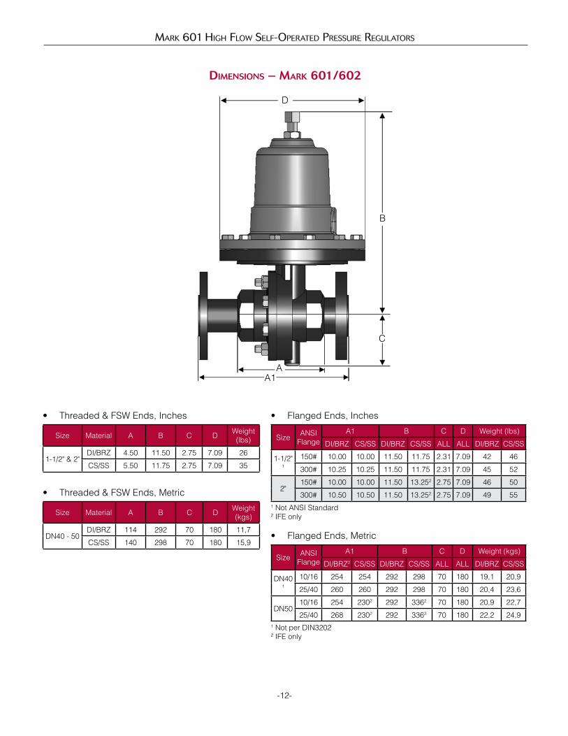
DiMensions – MarK 601/602
-12-
D
B
C
A1
Size ANSI Flange
A1 B C D Weight (lbs)
DI/BRZ CS/SS DI/BRZ CS/SS ALL ALL DI/BRZ CS/SS
1-1/2"1
150# 10.00 10.00 11.50 11.75 2.31 7.09 42 46
300# 10.25 10.25 11.50 11.75 2.31 7.09 45 52
2"150# 10.00 10.00 11.50 13.252 2.75 7.09 46 50
300# 10.50 10.50 11.50 13.252 2.75 7.09 49 55
• Flanged Ends, Inches
Size Material A B C D Weight(lbs)
1-1/2" & 2"DI/BRZ 4.50 11.50 2.75 7.09 26
CS/SS 5.50 11.75 2.75 7.09 35
• Threaded & FSW Ends, Inches
Size Material A B C D Weight(kgs)
DN40 - 50DI/BRZ 114 292 70 180 11,7
CS/SS 140 298 70 180 15,9
• Threaded & FSW Ends, Metric
Size ANSI Flange
A1 B C D Weight (kgs)
DI/BRZ2 CS/SS DI/BRZ CS/SS ALL ALL DI/BRZ CS/SS
DN401
10/16 254 254 292 298 70 180 19,1 20,9
25/40 260 260 292 298 70 180 20,4 23,6
DN5010/16 254 2302 292 3362 70 180 20,9 22,7
25/40 268 2302 292 3362 70 180 22,2 24,9
• Flanged Ends, Metric
1 Not ANSI Standard2 IFE only
A
1 Not per DIN32022 IFE only
9 & 10 DiaphragmS6 316SSTVI VitonBN Buna-NJL Jorlon
7 & 8 Spring Range PSI (Bar)53 20 - 45 (1,4 - 3,0)75 30 - 95 (2,1 - 6,6)97 60 - 160 (4,1 - 11,0)
-13-
Mark 601 HigH flOw Self-Operated preSSure regulatOrS
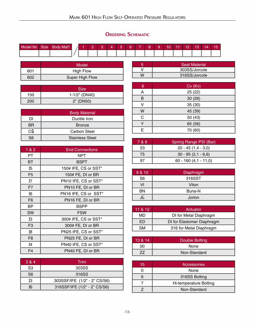
orDering scHeMatic
Model601 High Flow602 Super High Flow
Size150 1-1/2" (DN40)200 2" (DN50)
Model No Size Body Mat'l 1 2 3 4 5 6 7 8 9 10 11 12 13 14 15
1 & 2 End ConnectionsPT NPTBT BSPTI5 150# IFE, CS or SST*F5 150# FE, DI or BRI7 PN10 IFE, CS or SST*F7 PN10 FE, DI or BRI6 PN16 IFE, CS or SST*F6 PN16 FE, DI or BRBP BSPPSW FSWI3 300# IFE, CS or SST*F3 300# FE, DI or BRI8 PN25 IFE, CS or SST*F8 PN25 FE, DI or BRI4 PN40 IFE, CS or SST*F4 PN40 FE, DI or BR
Body MaterialDI Ductile IronBR Bronze CS Carbon SteelS6 Stainless Steel
3 & 4 TrimS3 303SSS6 316SSI3 303SSF/IFE (1/2" - 2" CS/S6)I6 316SSF/IFE (1/2" - 2" CS/S6)
6 Cv (Kv)A 25 (22)B 30 (26)V 35 (30)W 45 (39)C 50 (43)Y 65 (56)E 70 (60)
5 Seat MaterialV 303SS/JorcoteW 316SS/Jorcote
11 & 12 ActuatorMD DI for Metal Diaphragm ED DI for Elastomer DiaphragmSM 316 for Metal Diaphragm
13 & 14 Double Bolting00 NoneZZ Non-Standard
15 Accessories0 None6 316SS Bolting7 Hi-temperature BoltingZ Non-Standard
Jordan Valve a division of Richards Industries 3170 Wasson Road • Cincinnati, OH 45209 513.533.5600 • 800.543.7311 • 513.871.0105 (f)[email protected] • www.jordanvalve.com
Mark 601 HigH flOw Self-Operated preSSure regulatOrS
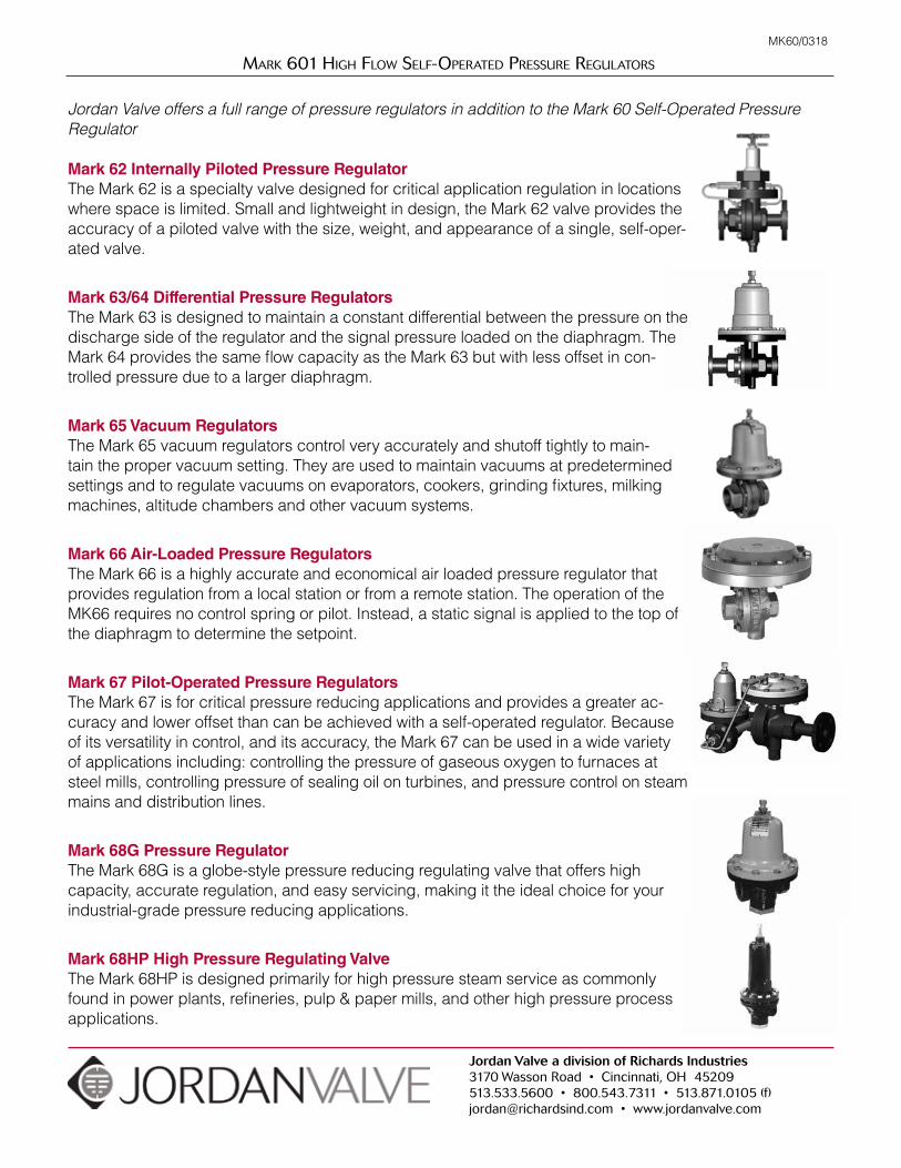
Mark 62 Internally Piloted Pressure RegulatorThe Mark 62 is a specialty valve designed for critical application regulation in locations where space is limited. Small and lightweight in design, the Mark 62 valve provides the accuracy of a piloted valve with the size, weight, and appearance of a single, self-oper-ated valve.
Mark 63/64 Differential Pressure RegulatorsThe Mark 63 is designed to maintain a constant differential between the pressure on the discharge side of the regulator and the signal pressure loaded on the diaphragm. The Mark 64 provides the same flow capacity as the Mark 63 but with less offset in con-trolled pressure due to a larger diaphragm.
Mark 65 Vacuum RegulatorsThe Mark 65 vacuum regulators control very accurately and shutoff tightly to main-tain the proper vacuum setting. They are used to maintain vacuums at predetermined settings and to regulate vacuums on evaporators, cookers, grinding fixtures, milking machines, altitude chambers and other vacuum systems.
Mark 66 Air-Loaded Pressure RegulatorsThe Mark 66 is a highly accurate and economical air loaded pressure regulator that provides regulation from a local station or from a remote station. The operation of the MK66 requires no control spring or pilot. Instead, a static signal is applied to the top of the diaphragm to determine the setpoint.
Mark 67 Pilot-Operated Pressure RegulatorsThe Mark 67 is for critical pressure reducing applications and provides a greater ac-curacy and lower offset than can be achieved with a self-operated regulator. Because of its versatility in control, and its accuracy, the Mark 67 can be used in a wide variety of applications including: controlling the pressure of gaseous oxygen to furnaces at steel mills, controlling pressure of sealing oil on turbines, and pressure control on steam mains and distribution lines.
Mark 68G Pressure RegulatorThe Mark 68G is a globe-style pressure reducing regulating valve that offers high capacity, accurate regulation, and easy servicing, making it the ideal choice for your industrial-grade pressure reducing applications.
Mark 68HP High Pressure Regulating ValveThe Mark 68HP is designed primarily for high pressure steam service as commonly found in power plants, refineries, pulp & paper mills, and other high pressure process applications.
MK60/0318
Jordan Valve offers a full range of pressure regulators in addition to the Mark 60 Self-Operated Pressure Regulator