Maritime Administration in cooperation with COATINGS ...dtic.mil/dtic/tr/fulltext/u2/a451939.pdf ·...
90
Product Breakdown Structure U.S. DEPARTMENT OF COMMERCE Maritime Administration in cooperation with Todd Pacific Shipyards Corporation
Transcript of Maritime Administration in cooperation with COATINGS ...dtic.mil/dtic/tr/fulltext/u2/a451939.pdf ·...

November 1980
THE NATIONALRATION SHIPBUl LDING
PBUILDING RESEARCHCOATINGS PROGRAM
Product Breakdown Structure
U.S. DEPARTMENT OF COMMERCEMaritime Administration
in cooperation with
Todd Pacific Shipyards Corporation

Report Documentation Page Form ApprovedOMB No. 0704-0188
Public reporting burden for the collection of information is estimated to average 1 hour per response, including the time for reviewing instructions, searching existing data sources, gathering andmaintaining the data needed, and completing and reviewing the collection of information. Send comments regarding this burden estimate or any other aspect of this collection of information,including suggestions for reducing this burden, to Washington Headquarters Services, Directorate for Information Operations and Reports, 1215 Jefferson Davis Highway, Suite 1204, ArlingtonVA 22202-4302. Respondents should be aware that notwithstanding any other provision of law, no person shall be subject to a penalty for failing to comply with a collection of information if itdoes not display a currently valid OMB control number.
1. REPORT DATE NOV 1980 2. REPORT TYPE
3. DATES COVERED 00-00-1980 to 00-00-1980
4. TITLE AND SUBTITLE Product Work Breakdown Structure
5a. CONTRACT NUMBER
5b. GRANT NUMBER
5c. PROGRAM ELEMENT NUMBER
6. AUTHOR(S) 5d. PROJECT NUMBER
5e. TASK NUMBER
5f. WORK UNIT NUMBER
7. PERFORMING ORGANIZATION NAME(S) AND ADDRESS(ES) Naval Surface Warfare Center CD,Code 2230 -Design IntegrationTower,9500 MacArthur Blvd Bldg 192 Room 128,Bethesda,MD,20817-5700
8. PERFORMING ORGANIZATIONREPORT NUMBER
9. SPONSORING/MONITORING AGENCY NAME(S) AND ADDRESS(ES) 10. SPONSOR/MONITOR’S ACRONYM(S)
11. SPONSOR/MONITOR’S REPORT NUMBER(S)
12. DISTRIBUTION/AVAILABILITY STATEMENT Approved for public release; distribution unlimited
13. SUPPLEMENTARY NOTES
14. ABSTRACT
15. SUBJECT TERMS
16. SECURITY CLASSIFICATION OF: 17. LIMITATION OF ABSTRACT
18. NUMBEROF PAGES
89
19a. NAME OFRESPONSIBLE PERSON
a. REPORT unclassified
b. ABSTRACT unclassified
c. THIS PAGE unclassified
Standard Form 298 (Rev. 8-98) Prescribed by ANSI Std Z39-18

FOREWORD The Product Work Breakdown Structure (PWBS) described herein is basedupon that used by Ishikawajima-Harima Heavy industries Co., Ltd. (IHI) ofJapan. It has been developed and refined during the construction of over 2,000ships in the last two decades. Thus, PWBS is not just based on theory. It has beenrepeatedly proven in all IHI shipyards and in other shipyards in Asia, Europe andSouth America which have adopted IHI methods.
PWBS employs the logic of Group Technology (GT) which is a method for ap-plying mass production techniques to a variety of products in widely varyingquantities. As applied to ship construction, PWBS classifies components to bepurchased, parts to be fabricated and planned subassemblies in order to achieveuniform and coordinated work flows. In shipbuilding, as in other industries, GThas yielded substantial benefits even when resources remained essentially unchanged.
The transition to PWBS has already begun in some U.S. shipyards. Implementa-tion is difficult only because of human problems. PWBS features unprecedented in-tegration of hull construction, outfitting and painting. Further, it features costcenters which exactly match a zone-oriented organization. Thus, it does not permitisolationist performers to claim credit without evaluating their impact on the work ofothers. Also, more so than ever before, PWBS puts “cross hairs” on the perform-ances of shipbuilding managers and workers.
I
IRON STURT, a 22,000-deadweight ton multi-purpose cargo carrier, the 5,200-displacernent ton helicopter destroyer SHIRANE (delivery March 1980) andthe 484,000-deadweight ton tanker GLOBTIK TOKYO, not shown, were all constructed by IHI with the PWBS described herein.
ACKNOWLEDGEMENTS The author is Y. Okayama, Consulting Group Manager, IHI International Divi-sion.
The editor and contributing author is L.D. Chirillo, R&D Program Manager,Todd Pacific Shipyards Corporation, Seattle Division.
Special appreciation is expressed to H. Tamura, M. Muraoka, Y. Tamura,N. Yamamoto, F. Kojima and M. Fukuda, truly professional shipbuilders of IHI’sKure Shipyard, for their contributions and to L.F. McGinnes, School of Industrial& Systems Engineering, Georgia Institute of Technology, for participating in theediting effort. Appreciation is also expressed to Y. Mikami, M. Kuriki and Y.Ichinose, of IHI Marine Technology and to the people in Todd Seattle, particularlyD.S. Hunter and A.E. Clark, who furnished essential support.
This book is a cooperative effort by Todd, the Maritime Administration’s Officeof Advanced Ship Development and the Ship Production Committee of the So-ciety of Naval Architects and Marine Engineers~

This book is dedicated to the memory ofa ship-material supplier
from San Francisco, California
James A. StasekDecember 31, 1925 — September 1, 1980
ii

TABLE OF CONTENTS
iii

i v

LIST OF FIGURES
1-1 Reiterative Development of Work Packages . . . . . . . . . . . . . . . . . . . . . ...21-2 Outfit Units . . . . . . . . . . . . . . . . . . . . . . . . . . . . . . . . . . . . . . . . . . . . . . . . . . 31-3 Three Dimensional Product Work Breakdown Structure . . . . . . . . . . . ...41-4 T,N and Q are Interdependent Variables . . . . . . . . . . . . . . . . . . . . . . . . ...51-5 Balanced T,N and Q . . . . . . . . . . . . . . . . . . . . . . . . . . . . . . . . . . . . . . . . . .51-6 Work Package Decision Logic Table . . . . . . . . . . . . . . . . . . . . . . . . . . . . . . 6
2-1 Dual Grouping in the Management Cycle . . . . . . . . . . . . . . . . . . . . . . . ...72-2 Product-oriented Design Process. . . . . . . . . . . . . . . . . . . . . . . . . . . . . . ...82-3 ZOFM Design and Production Organizations . . . . . . . . . . . . . . . . . . . . ...92-4 Integrated Work Processes . . . . . . . . . . . . . . . . . . . . . . . . . . . . . . . . . . . . . 102-5 Integrated Schedules . . . . . . . . . . . . . . . . . . . . . . . . . . . . . . . . . . . . . . . . . . 11
3-13-23-33-43-53-63-73-83-93-103-113-123-133-143-153-163-173-183-19
HBCM Manufacturing Levels . . . . . . . . . . . . . . . . . . . . . . . . . . . . . . . . . . . 14HBCM Product Aspects . . . . . . . . . . . . . . . . . . . . . . . . . . . . . . . . . . . . ...15Part Fabrication . . . . . . . . . . . . . . . . . . . . . . . . . . . . . . . . . . . . . . . . . . . ...16Part Assembly . . . ......................................... . . . . . . . . . . ....17 Sub-block Assembly . . . . . . . . . . . . . . . . . . . . . . . . . . . . . . . . . . . . . . . ...18Block Assembly . . . . . . . . . . . . . . . . . . . . . . . . . . . . . . . . . . . . . . . . . . . . . . 20Semi-block and Block Assembly--Bottom Center . . . . . . . . . . . . . . . ...21Block Assembly and Grand-block Joining-Top Wing . . . . . . . . . . . ...22Semi-block and Block Assembly—Bottom Wing and Side . . . . . . . . ...23Block Assembly and Grand-block Joining-Bulkhead . . . . . . . . . . . . ...24Block Assembly and Grand-block Joining-Stern . . . . . . . . . . . . . . . ...25Block Assembly-Upper Deck and Engine-room Flat . . . . . . . . . . . . ...26Semi-block and Block Assembly—Bow . . . . . . . . . . . . . . . . . . . . . . . . . . . 27Semi-block and Block Assembly--Fo’c’sle . . . . . . . . . . . . . . . . . . . . . ...28Grand-block Joining--Fo’c’sle . . . . . . . . . . . . . . . . . . . . . . . . . . . . . . . . . . 29Block Assembly and Grand Block Joining--Engine-roomBottom . . ...30Block Assembly-Side Shell of Engine Room . . . . . . . . . . . . . . . . . . . ... 31ZOFM Manufacturing Levels . . . . . . . . . . . . . . . . . . . . . . . . . . . . . . . . . . . 34ZOFM Product Aspects . . . . . . . . . . . . . . . . . . . . . . . . . . . . . . . . . . . . . . . 35

3-203-213-223-233-243-253-263-273-283-293-303-313-323-333-343-353-363-373-383-393-403-413-423-433-443-453-463-473-483-493-503-51
Area Subdivisions for Design and Material Preparations . . . . . . . . . . ...36Various Outfit-unit Sizes . . . . . . . . . . . . . . . . . . . . . . . . . . . . . . . . . . . . ...38Standard Machinery Unit . . . . . . . . . . . . . . . . . . . . . . . . . . . . . . . . . . . . . . 39Lube-oil Cooler Unit . . . . . . . . . . . . . . . . . . . . . . . . . . . . . . . . . . . . . . . ...39Hatch Cover and Coaming Unit . . . . . . . . . . . . . . . . . . . . . . . . . . . . . . . . . 39General-service Pump Unit . . . . . . . . . . . . . . . . . . . . . . . . . . . . . . . . . . . . . 39Radar Mast and Foremast Units . . . . . . . . . . . . . . . . . . . . . . . . . . . . . . . . . 40On-block Outfitting--PipeTunnel. . . . . . . . . . . . . . . . . . . . . . . . . . . . . . .4IOn-block Outfitting-Engine-room Tank Top . . . . . . . . . . . . . . . . . . . . . . . . . . . . . .41ZPTM Manufacturing Levels . . . . . . . . . . . . . . . . . . . . . . . . . . . . . . . . .44ZPTM Product Aspects . . . . . . . . . . . . . . . . . . . . . . . . . . . . . . . . . . . . . . ..45ZPTM Paint Systems . . . . . . . . . . . . . . . . . . . . . . . . . . . . . . . . . . . . . . . . . . 46Grand Block--Deck and Bulkhead . . . . . . . . . . . . . . . . . . . . . . . . . . . . . .47Grand Block--Side Shell . . . . . . . . . . . . . . . . . . . . . . . . . . . . . . . . . . . . . . . 48Grand Block--Side Shell During Erection . . . . . . . . . . . . . . . . . . . . . . ...48On-ceiling Outfitting-Bow . . . . . . . . . . . . . . . . . . . . . . . . . . . . . . . . . . . . 49On-floor Outfitting-Bow . . . . . . . . . . . . . . . . . . . . . . . . . . . . . . . . . . . . . 49On-ceiling Outfitting-Engine-room Flat . . . . . . . . . . . . . . . . . . . . . . . ..50Engine-room Flat-After On-floor Outfitting. . . . . . . . . . . . . . . . . . . . . .50On-floor Outfitting-Engine-room Flat. . . . . . . . . . . . . . . . . . . . . . . . ...51Erection--1st Engine-room Flat . . . . . . . . . . . . . . . . . . . . . . . . . . . . . . . ..5 IOn-ceiling Outfitting-Accommodation Start . . . . . . . . . . . . . . . . . . . ...52On-ceiling Outfitting-Accommodation Completion . . . . . . . . . . . . . ...52Grand-block Joining-Superstructure . . . . . . . . . . . . . . . . . . . . . . . . . . . . 53Keel Laying Plus 11 Workdays . . . . . . . . . . . . . . . . . . . . . . . . . . . . . . . ...53Keel Laying Plus 13 Workdays . . . . . . . . . . . . . . . . . . . . . . . . . . . . . . . . . . 54Keel Laying Plus 15 Workdays . . . . . . . . . . . . . . . . . . . . . . . . . . . . . . . ...54Keel Laying Plus 19 Workdays . . . . . . . . . . . . . . . . . . . . . . . . . . . . . . . . . . 55Keel Laying Plus 22Workdays--Aft . . . . . . . . . . . . . . . . . . . . . . . . . . ...55Keel Laying Plus 22 Workdays—Foreward . . . . . . . . . . . . . . . . . . . . . ...56Keel Laying Plus 24 Workdays . . . . . . . . . . . . . . . . . . . . . . . . . . . . . . . ...56Keel Laying Plus 24 Workdays-Main Engine . . . . . . . . . . . . . . . . . . ...57
vi

3-52 Keel Laying P1us 27 Workdays . . . . . . . . . . . . . . . . . . . . . . . . . . . . . . . ...573-53 Keel Laying PIus 28 Workdays . . . . . . . . . . . . . . . . . . . . . . . . . . . . . . . ...583-54 Keel Laying Plus 29 Workdays . . . . . . . . . . . . . . . . . . . . . . . . . . . . . . . . . . 583-55 Keel Laying Plus 29 Workdays-Completing Superstructure . . . . . . . ...593-56 Operation IRON STURT . . . . . . . . . . . . . . . . . . . . . . . . . . . . . . . . . . . ...59
4-1 PPFM Manufacturing Levels . . . . . . . . . . . . . . . . . . . . . . . . . . . . . . . . ...624-2 PPFM Product Aspects . . . . . . . . . . . . . . . . . . . . . . . . . . . . . . . . . . . . . ...634-3 Area Subdivisions for PPFM Asembly and Joining . . . . . . . . . . . . . . ...644-4 Differences in Grouping PPFM . . . . . . . . . . . . . . . . . . . . . . . . . . . . . . . ..64
5-1 Identification Codes for Material . . . . . . . . . . . . . . . . . . . . . . . . . . . . . ...685-2 Material Cost Classifications . . . . . . . . . . . . . . . . . . . . . . . . . . . . . . . . . . . . 685-3 Cost Centers . . . . . . . . . . . . . . . . . . . . . . . . . . . . . . . . . . . . . . . . . . . . . . . . . 705-4 Indices for Monitoring Man-hours, Progress and Productivity . . . . . . . ..7l5-5 Cost Classifications and Charging Methods for Facilities
and Expenses . . . . . . . . . . . . . . . . . . . . . . . . . . . . . . . . . . . . . . . . . . . . . ...72
6-16-26-36-46-56-66-76-86-96-106-116-12
Management Cycle . . . . . . . . . . . . . . . . . . . . . . . . . . . . . . . . . . . . . . . . ...73Manpower Expenditures--Hull Construction . . . . . . . . . . . . . . . . . . . ...75Manpower Expenditures--Machinery Fitting . . . . . . . . . . . . . . . . . . . . . .75Manpower Expenditures--Electrical Assembly Less Cable . . . . . . . . ...75Manpower Expenditures-EIectrical Assembly Cable . . . . . . . . . . . . . . . . 75Production Progress—Hull Construction . . . . . . . . . . . . . . . . . . . . . . . . . 75Productivity--Parts Fabrication . . . . . . . . . . . . . . . . . . . . . . . . . . . . . . . . . 75Productivity--Subassembly and Block Assembly . . . . . . . . . . . . . . . . ...76Productivity--Erection . . . . . . . . . . . . . . . . . . . . . . . . . . . . . . . . . . . . . . . . 76Productivity--Machinery Fitting . . . . . . . . . . . . . . . . . . . . . . . . . . . . . . . . 76Productivity--Electrical Fitting Less Cable . . . . . . . . . . . . . . . . . . . . . ...76Productivity Control Group . . . . . . . . . . . . . . . . . . . . . . . . . . . . . . . . . . . . 76
vii

“A productive shipbuilding industryis an indispensable element of seapower. ”
The Editor
“Whosoever commands the sea commandsthe trade; whosoever commands the trade
of the world commands the riches ofthe world, and consequently, the
w o r l d i t s e l f ”
Sir Walter Raleigh1552 — 1618
VIII

The work required for any large construction projectmust be subdivided in order to be readily analyzed andmanaged. Any such subdivision scheme is a work break-down structure.
Traditional shipbuilders employ work subdivisions byships’ functional systems which are natural and appropriatefor estimating and for early design stages. However, systemorientation for planning, scheduling and execution is un-natural and inappropriate because it leads to poor coordina-tion of work and generally results in work packages whichare too large for effective control of material, manhours andschedules.
The way that ships, and most other manufactured arti-facts, are actually produced is by procuring or fabricatingparts and joining them to create subassemblies. In turn,these are combined through several manufacturing levels toproduce increasingly larger subassemblies. Thus, the idealway to subdivide ship-construction work is to focus onneeded parts and subassemblies, i.e., the actual interimproducts that preoccupy workers. A scheme to subdividework in accordance with art interim-product view, is aproduct-oriented work breakdown structure.
The need for a product-oriented work breakdown struc-ture which conforms with the way a ship is built was iden-tified for U.S. shipbuilders over a decade ago.1 At that timethere were already substantial applications by some ship-builders abroad.
1.1 Conformance With Group Technology
Unlike system-oriented methodologies, product orienta-tion facilitates identifying work by classes of problems.Where applied and exploited by shipbuilders, the logic andprinciples of Group Technology (GT) emerged independent
1.0 INTRODUCTION
of similar developments elsewhere to enhance machine toolusage. 2
In industries which produce machined parts, GT is ameans for improving productivity, even for a variety ofcustom requirements, by grouping parts by their commoncharacteristics. The basis for such groups, or families, isthat there are common processes for the manufacture of allparts within a group. Thus, parts are classified by bothdesign and manufacturing attributes which are reflected incoding schemes. The codes typically address form, dimen-sions, tolerances, material, and types and complexity ofmachining operations. They reflect need for exact identifica-tion of previously manufactured parts for the purpose ofretrieving process standards.
In shipbuilding it is the interim products, i.e., fabricatedparts and various Subassemblies, which are susceptible tosimilar classification by the problems their manufacture im-poses. Such classifications are the singular means used bythe world’s most competitive shipbuilders to plan work.They are able to more uniformly distribute work betweencontract award and delivery for each ship and better coor-dinate the outputs of work-process lanes even for asimultaneous mix of ship types and sizes. Thus, they achievemany of the benefits of batch manufacturing while produc-ing interim products that are manifestly unlike each other.3
Unique classification by certain product aspects conven-tionally relate a part or subassembly to a system or zone of aship design and also to the work processes by problem areaand by work stage. Thus, product aspects are classificationsfor both design and manufacturing attributes. This conceptcombined with a greater degree of interaction betweendesign and production specialists has proven to be a power-ful means for improving productivity.4
1"A Study of Shipbuilding Cost Estimating Methodology” for the maritime Administration by Engineering & Management Sciences Corporation dated 20January 1969.
2Group Technology is “... the logical arrangement and sequences of all facets of company operations in order to bring the benefits of mass production to highvariety, mixed quantity production.” Group Technology A Foundation for Better Total Company Operation, G.M. Ranson, McGraw-Hill, London, 1972,p.1. Group Technology is also called Family Manufacturing.
3 Also called pseudo-batch manufacturing.
4 Where successfully applied there is much dependence on field engineers. In the Aioi Shipyard of Ishikawajima-Harima Heavy Industries Co., Ltd. (IHI), near-ly 2% of the 1060 people assigned to hull construction fabrication and assembly are field engineers. They number almost 6% of the 715 people so assigned tooutfitting and painting. Circa June 1980.
1

Work packages classified by product aspects are system-atically analyzed in order to determine their productivityvalues. As shown in Figure 1-1, the analyses may be reiter-ative through several planning levels. Where such invest-ment is made, the work packages are immediately improvedbased upon restudy following production. Thus, the workpackages reflect an accumulation of experiences. They are,to a remarkable degree, adaptable to ships of different sizesand types, therefore initial costs justify amortization oversubsequent ship construction projects.5
The independent emergence of the logic and principles ofGT in shipbuilding caused the development of codes whichtypically address type of work, resources required andunique product aspects. The latter include zone codes whichdesignate disposition of an interim product for laterassembly of a larger interim product. Significantly, the
FIGURE I-1: The reiterative development of work packages. Designand material definition are regarded as aspects of planning.
codes do not reflect need to identify whether a particular in-terim product has been made before as the classificationsapply to ship designs of any type and size that are custom-ized to any degree.
Emphatically, the codes do provide for identification ofwork problems imposed. Thus, interim products which aredifferent looking from each other and for different ships,are grouped together for processing in accordance with acommon set of solutions; see Figure 1-2.
1.2 Work Package Classifications
The concepts of the Product Work Breakdown Structure(PWBS) described herein, Group Technology (GT) andFamily Manufacturing (FM) are similar. All featureclassifications to permit grouping of products by similaritiesin production problems without regard for end-use systems.Logically the PWBS first divides the shipbuilding process in-to three basic types of work: hull construction, outfittingand painting, because each imposes problems that are in-herently different from the others’. Further, each is readilysubdivided into fabrication and assembly types of work.6 Itis these assembIy subdivisions that are naturally linked tozones and which are the basis for zone dominance in themanagement cycles of the most competitive shipbuildingfirms. Zone-oriented production, i.e. the Hull Block Con-struction Method (HBCM), is already being applied for hullconstruction by most shipyards. But, the same logic is notyet everywhere employed for outfitting by zones which ismore complex and difficult to undertake.7
Secondly, PWBS classifies interim products in accord-ance with their needs for resources, i.e. material, man-power, facilities and expenses. Thus for example, differentstructural panels regardless of their intended locations in aship, have resources classified and allocated in accordancewith common parameters. Likewise, different outfit unitsare treated the same way. Definitions of the productresources are:
● Material, to be used for production, either direct or in-direct, e.g., steel plate, machinery, cable, oil, etc.
• Manpower, to be charged for production, either director indirect, e.g., welder, gas cutter, fitter, finisher, rig-ger, material arranger, transporter, etc.
• Facilities, to be applied for production, either direct orindirect, e.g., buildings, docks, machinery, equipments,tools, etc.
• Expenses, to be charged for production, either direct orindirect, e.g., designing, transporation, sea trials,ceremonies, etc.
S Regardless of differences in functional systems, zone/area/stage classifications of comparable work packages for different size ships of the same type, changevery little. Even for different type ships, such classifications remain essentially the same for work related to bows, sterns, engine rooms and superstructures
6 Painting-fabrication applies to the manufacture of paint painting-assembly applies to its application. The former is usually not applicable in shipyards.
7 A methodology for zone outfitting was introduced to U.S. shipbuilders by the publication of “Outfit Planning -December 1979” by C.S. Jonson and L.DChirillo, for the National Shipbuilding Research Program.
2

FIGURE 1-2: Outfit units which are dissimilar in arrangement and in functionsincorporated, have the same classification in a product-oriented work breakdownstructure because the problems associated with their assembly are the same.
In order to optimize productivity in realistic circum-stances, a ship must be constructed in accordance with acarefully established plan that envisions:
• processes for manufacturing parts and subassembliesleading to outfit units and structural blocks within timeframes that can be coordinated, and
● simultaneous use of each process for the requirementsof different systems even in different ships.
The third classification, by the four product aspects, addressesthese needs because it contains essentials needed for controlof production processes.
Two product aspects, system and zone are means fordividing a ship design into planned manageable parcels.Each, for example, can apply to a number of parts or to onespecific assembly. Each of the latter is usually addressed bya separate work package. The other two product aspects,area and stage, are means for dividing the work processfrom material procurement to complete ship delivery. Theproduct aspects are:
● System - A structural function or an operational func-tion of a product, i.e., longitudinal bulkhead, trans-verse bulkhead, mooring system, fuel-oil service system,lighting system, etc.
● Zone - An objective of production which is anygeographical division of a product, e.g., cargo hold,
3
superstructure, engine room, etc., and their sub-divi-sions or combinations [e.g., a structural block or outfitunit, a subassembly of either and ultimately a part orcomponent).
● Area - A division of the production process intosimilar types of work problems which can be
- by feature (e.g., curved vs. flat blocks, steel vs.aluminum structure, small diameter vs. large diameterpipe, pipe material, etc.)
- by quantity (e.g., job-by-job vs. flow lane, volume ofon-block outfitting for machinery space vs. volume ofon-block outfitting for other than machinery space,etc.)
- by quality (e.g., grade of workers required, grade offacilities required, etc.)
- by kind of work (e.g., marking, cutting, bending,welding, blasting, bolting, painting, testing, cleaning,etc.), and
- by anything else that creates a manifestly differentwork problem.
● Stage - a division of the production process by se-quences, e.g., sub-steps of fabrication, sub-assembly,assembly, erection, outfitting on-unit, outfitting on-block, and outfitting on-board.

The three-dimensional nature of the Product Work Break-down Structure (PWBS) described in the foregoing is illus-trated in Figure 1-3.
1.3 Work Package Productivity Value
When an interim product is identified by product aspects,it is necessary to evaluate its efficiency as a work packagewhich can be expressed by the formula
P V = f ( T , N , Q )
where:
PV = productivity value, i.e., the productive efficiencyof a work package
T = time allowed for its accomplishment, i.e. workingtime
N = number of of units of resources; particularly com-ponents in the material list and man-hours allocated
Q = quality of work circumstance, e.g., downhand vs.overhead, high vs. low, etc., and also quality specifiedfor the interim product
T, N and Q are interdependent and as shown in Figure 1-4they impact differently on PV. As they cannot be evaluatedseparately it is useful to symbolize PV as a triangle havingsides that represent T, N and Q. Optimum PV is thenrepresented by an equilateral triangle, see Figure 1-5. In
other words, PV is optimized when the influences of T, Nand Q are balanced.
The function f(T, N, Q) must be determined empiricallyby each shipyard and separately for each classification ofthe production process by problem area. In addition, eachsuch determination must consider the immediate precedingand following work stages. For example, Q includes con-sideration of the quality specified for an interim product. Ifits contribution to PV is not enough, the quality of the in-terim product is not good enough for a larger assembly.
Further, productivity values cannot be precisely deter-mined. Therefore, they are guidance to serve a judgementalprocess for evaluating work packages. Their use at first in-volves trial and error and thereafter experience. For examplea geographical division of a product into seemingly idealzones, could yield unacceptable work packages when theneeded work processes are analyzed by problem areas. Zoneboundaries wouId then be adjusted until there is an idealcompromise of zone and area considerations. Each propos-ed work package should be so evaluated regardless ofwhether it has been employed in the past. It is probable thatsome circumstance, especially regarding resources and timeavailable, will have changed.
Figure 1-6 shows the applicability of PWBS to a variety ofindustrial methods. It is a decision logic table for evaluatingwork packages associated with all of the theoreticallyavailable combinations of product aspects. Where ex-
4

T N
Q
FIGURE 1-4: T, N and Q are interdependent variables. However,each one influences PV differently.
perience exists, many evaluations are not necessary andsome are performed intuitively. The remainder areevaluated with the assistance of equations similar to thatdescribed in the foregoing.
1.4 Versatility and Benefits
From a product-oriented viewpoint each work packagecan address, theoretically, all four of the product aspects.But sometimes to fulfill other needs certain product aspectsmay be disregarded. When zone is eliminated, grouping ismade by system, area and stage. This is the traditionalSystem (-oriented) Work Breakdown Structure (SWBS). Ifsystem is deleted, grouping is made by zone, area and stage.This is called a Zone (-oriented) Work Breakdown Structure(ZWBS). If both system and zone are disregarded, groupingis by area and stage. This is an area-oriented workbreakdown structure, a term not generally used. Figure 1-6is marked to show specific examples of system, zone andarea orientations.
Shipbuilding methods have consistently become moreproductive during the past three decades mainly because ofthe change from traditional system-oriented processes to thefollowing zone-oriented processes:
• Hull Block Construction Method (HBCM),
• Zone Outfitting Method (ZOFM), and
• Zone Painting Method (ZPTM).
5
T
Q
FIGURE 1-5: PV is optimized when the influences of T, N and Q arebalanced.
Further productivity increases were achieved by adoption ofthe area-oriented Pipe Piece Family Manufacturing Method(PPFM). These proven concepts have significantly con-tributed to:
• simpler assembly methods,
• the rationalization and automation of facilities, and
• more uniform and simultaneous workloads for fabrica-tion shops and assembly teams.
Their benefits are manifested by:
• improved safety,
● improved work environments,
● better quality, and
• higher productivity.


2.0 AN APPROACH TO PRODUCT WORKBREAKDOWN STRUCTURE (PWBS)
Many shipyards are equipped with modern enoughfacilities having sufficient capacity to build many types andsizes of both commercial and naval ships. However, theperiods usually allowed for design and production are muchlonger than that needed by competitive shipbuilders withcomparable facilities. As a consequence, their productionlevels relative to facilities are unnecessarily low. Significantreasons for this state of affairs are their adherence tosystem-oriented work breakdowns, continued dependenceon system-oriented design and production organizations,and dependence on divisions of ship designs by systems forallocations of material and manpower.
2.1 Dual Grouping
In conventional shipbuilding, all functions of themanagement cycle, i.e., estimating, planning, scheduling,executing and accounting, are consistently system oriented.Cost classifications for estimated material and manpowerrequirements are by system. Typically, drawings andmaterial lists are issued per system and work packages arebroken down within each system for scheduling, executingand evaluating. From a limited managerial viewpoint, suchconsistency is favorable.
In contrast, PWBS has more than one character. It per-mits dual groupings, e.g., work packages by product aspectsand cost classifications by product resources. Thus, man-power expenditures can be collected by zone/area/stagewhile material costs can be collected by system. The uniquemultiple character of PWBS is illustrated in Figure 2-1.
2.2 Design and Material Definition
The transformations of design and material definitionfrom system to zone orientations are illustrated in Figure2-2. As shown, a ship as a total system is separated into in-dividual systems on functional drawings for which materiallists by system are prepared. Transformation to zone orien-tation begins with a block plan for hull construction andcomposite drawings for outfitting. These incorporate allsystems and show zone boundaries. They are further proc-essed to add area/stage considerations which for hull con-struction are designated on assembly, subassembly and cut-ting plans. For outfitting, they are designated on workingdrawings (work instruction drawings) each of which isdeveloped together with its own material list of fittings foreither on-unit, on-block or on-board outfitting. The hierar-
chiprecomliststinui.e.req
7
cal subdivision continues by zone/area/stage with theparation of detail design drawings for pipe pieces andponents other than pipe and their respective material. As also shown in Figure 2-2, the planning process con-es until each zone is broken down to a minimum level.
, components that are to be purchased and the material-
uirements for such parts that are to be fabricated.
Transformationin accounting
FIGURE 2-1: Dust grouping in the management cycle facilitated by aProduct Work Breakdown Structure (PWBS). Design and materialdefinition are aspects of planning. Material procurement is as much apart of executing as is producing.

TOTAL SYSTEM SYSTEM
DETAIL DESIGN (WORKING DRAWINGS)
FUNCTIONAL DESIGN
BASIC DESIGN
CUlTiNGPLAN
COMPOSITES WORK INSTRUCTION & MATERIAL DETAIL DESIGN DRAWINGS
[I l l
MLC
PIPE CUTTlNGPLAN
PIPE PIECEMANUF.
LANE PLAN
etc. II I PIPINGDIAGRAM
FIGURE 2-2: Pridyct-freehand. But, they aredesignate stages during
kI
oriented Design Process. Transition Design introduces zones and interrelations with systems. The items markedsufficient for quickly conveying arrangements and system/zone relationships to detail designers. The latter refinepreparation of work instruction and material detail-design drawings.
CABLECUTTING
PLAN
“•“ are sometimesarrangements and
8

ELECTRIC
PIPE
DECK FABRICATION SHOP
OUTFlTTlNGz DESIGN GROUP DECK
OUTFlTTING SECTION
ACCOMMODATIONOUTFlTTING ACCOMMODATtON
DESIGN GROUP OUTFlTTING SECTION
MACHINERY MACHINERYOUTFITTING OUTFlTTING SECTION
DESIGN GROUP
ELECTRICELECTRIC
OUTFITTINGOUTFITTING SECTION
DESIGN GROUP PRODUCTION PIANNING& ENGINEERING GROUP
FIGURE2-3: Where the zone Outfitting Method (ZOFM) is used, design and production are organized to specialize by fabrication and assembly prob-lems associated with deck, accmmodation, machinery and electrical outfitting. This conforms with a basic tenet of Group Technology (GT), i.e.,matching classes of problems to sets of solutions.
Product-oriented design features a sequence for groupingproduct aspects, i.e., by total system, - individual - system,system/zone and zone/area/stage. These groupings arerespectively employed in basic design, functional design,transition design and detail design. Obviously, there is aneed to manage a transition which interrelates systems andzones for each ship design as is already being done for hullconstruction by some shipbuilders who have not totallyadopted zone orientation.
The zone-oriented Hull Block Construction Method(HBCM) achieved acceptance in traditional design organiza-tions probably because in these organizations, all hull struc-tural systems are assigned to a single design group. Thisfacilitates the coordination needed to produce a block planwhich accurately reflects the apportionment of parts of hullsystems to specific blocks.
In contrast, the outfit systems are assigned to separatedesign groups in a traditional design organization. Thisseparation of design responsibilities by system is satisfactoryfor functional design but is not suitable for detail design. Itperpetuates preparation of expensive and unnecessarysystem-arrangement drawings resulting in delayed prepara-tion of needed composite drawings. Primarily because ofthe multiplicity of outfit design groups, it is difficult todefine interim products on detail design drawings byzone/area/stage and to provide structured material lists.Both are essential for zone-oriented material procurementand for control of work flows in process lanes.
Therefore, where zone outfitting has been adopted someshipbuilders have reorganized design, and even production,by classes of problems. Typical such classes as shown in
Incorporating electrical as a fourth classification is a concession to tradition. Pbuilding, assembly of electrical systems will be Planned just as if they were pilogical to classify electrical as a type of work analogous to hull construction
9
Figure 2-3. are deck. accommodation. machinery and elec-
are assigned to a-group having responsibilities for a singleproduction-problem class. Within such groups there is im-proved “horizontal” communication such as that betweenpiping and vent duct designers assigned to machinery outfit-ting. They become more expert about their particular class,are led away from insignificant fine tuning of systems, andinstead focus on composite drawings marked to show how aship is to be assembled and on structured material lists. Theyhave eliminated system arrangement drawings and havedeveloped surprisingly interference-free and simplified com-posites (drawings or scale models) directly from diagram-matrics.
2.3 Producing
Figure 2-4 shows work process lanes, organized by classesof problems, and how their end products must integrate forzone-oriented production. Fabrication shops and assemblysections are grouped along the various process lanes.
Traditionally, hull construction has always been assignedto a single producing division associated with a single tradeunion. Therefore, the general adoption of hull block con-struction in process lanes similar to those illustrated inFigure 2-4 is not surprising. However, the outfit and inte-grated (hull construction and outfit) process lanes shown arequite different from those of shipbuilders who still usesystem-oriented work packages for outfit fabrication andassembly.
erhaps when there is general use of electric-cable splices solely to facilitate ship-pe or vent-duct systems. If the latter is unacceptable to traditionalists, it is more, outfitting and painting.

FIGURE 2-4.: Simplified integrated processes for simultaneous hull construction andon fitting, Painting would appear as additional processes in additional sub-stages in
sages, such as block turnover when outfitting on block, are also omitted.
PART FORFLAT FLAT
FLAT
PANELPANEL
PANEL BLOCK
PART FORCURVED CURVEO CURVED
PANEL PANEL 5PANEL BLOCK
MATERIALCUTTING
BENDINGI
ASSEMBLY ASSEMBLY
MATERIAL PART FABRICTIONSUBLOCK
BLOCK
P - - - - - - - - - -
DECKCURVED P'L
i
I
MATERIAL I 1 IMANUFACTURING PALLETIZINQ UNIT ASSEMBLY ON BOLOCK ON ORAND BLOCK
MATERIALCUTTING ASSEBLY BENDING P A L L E T I Z I N G UNIT ASSEMBLY ON BLOCK OUTFITTING
- - - - - - - I
9
ON BOAROOUTFITTING
lNTEGRATED WITHHULL
ERECTION

FIGURE 2-5: Organization of integrated Hull Construction, Outfitting and Painting Schedules. The position of the Block Erection Master Scheduleis an indicator of the importance of blocks defined to facilitate outfitting and painting its addition to huIl construction throughput.
For example, in a system-oriented production organiza-tion workers are assigned to a pipe shop which fabricatesand assembles pieces required for all pipe systems. In azone-oriented organization, such workers are assignedeither to a fabrication shop or to a team specialized for aspecific category of assembly problems. In addition toassembling all but high pressure pipe, each fitter assembleseverything for which a manual “stick” welder or spannerwrench suffices, e.g., pipe supports, walkways, handrails,electric-cable trays, pipe and vent-duct pieces, etc. Othertrades represented on a team are as needed for special or ex-
Even where traditional system-organizations exist, thereare means for an almost equally effective assignment ofmanpower. At least one shipyard, having a contract withone labor union which includes all trades, can assign peopleof one trade to assist those of another to a reasonabledegree. Further in another shipyard, the introduction of justzone-oriented hull construction has contributed to the com-bining of many related specialists into two, i.e., a fitter whodoes some welding and a welder for special or large amountsof welding. Therefore it is probable that a generalunderstanding of the benefits of zone outfitting will similar-
some shipbuilders abroad assign a team that is specialized in the productio
' Some unionists advocate productivity improvement as a means for achievinthe United Steel Workers said “Where we see poor maintenance or the failuwith management.” Business Week: December 24, 1979; p 46.
11
Iy encourage development of an “outfitter” trade asdescribed in the foregoing paragraph.
Zone-oriented worker skills should not be isolated to justan objective of management because they are also creditedfor significantly improving safety, work environment, quali-ty and productivity. All are justification to include zone out-fitting in the bargaining positions of both labor andmanagement.3
2.4 Controlling
Zone-oriented scheduling is necessary to control the flowsof work on various process lanes so that the creation of in-terim products anticipates only immediate needs. Suchscheduling coordinates hull construction, outfitting andpainting and allows periods after work stages for the collec-tion and distribution of interim products to other work sta-tions. The goal is to minimize buffer stowages. Thus, inte-grated schedules as shown in Figure 2-5 are essential for theperiod starting with fabrication through final outfitting.The schedules should address all fabrication and assemblywork including lofting and painting.
n of interim products of a particular problem class.
g job security. AS a consequence of a few steel plant shutdowns the President ofre to innovate and Stay modem we will make such matters a subject of discussion

The most detailed schedule, e.g., a weekly schedule,should be based upon work packages which, ideally, aresized for work to be performed by two people in one week.Such work package sizes, relatively small compared to thoseused for system-oriented methods, facilitate control of workflows and accurate progress reporting of manpower andmaterial costs by zone/area/stage.
The need for small work packages cannot be understated.With structured material lists they are the very essence ofcontrol because
. progress determinations are based upon only tangibleaspects, i.e., material is either unassembled or assem-
● the greater number of work activities enhance flexibility.
Flexibility, i.e., the wherewithal to quickly identify goodoptions based upon constant feedback about material pro-curement and work progress, is necessary for successful useof PWBS. Adjustments are needed to counter potentialdelays and early completions. Adjustments could includetransfer of workers between process lanes, the use of over-time or short term schedule changes. The objectives are tomaintain uniform work flow within each process lane and
Composing the prerequisite work packages could be amajor stumbling block without the benefit of prior ex-perience, particularly for shipyards which have not yet in-stituted the Hull Block Construction Method (HBCM).However, the goal is clear; work packages per ship shouIdbe uniform in work content as much as possible. Regardlessof the difficulties, managers have to keep in mind that workby system is inherently associated with diminished control.System orientation features relatively large work packageswhich do not address modem shipbuilding methods.Primarily they are ineffectual for control because they re-quire execution over relatively long time periods. It is axio-matic, without effective control, costs are higher regardlessof the disciplines applied for their collection.
2.5 Costing
Zone orientation introduced the powerful concept of con-trol linked to many relatively small amounts of materialgrouped by zone/area/stage. Where applied, progressreporting and cost collections are zone oriented so thatmanagers have tangible means of corroborating work com-pleted in order to forecast work remaining and resources re-quired for completion. In order to serve estimators, man-power costs by system have to be rationalized. Certain in-dices, described in Chapters 5.0 and 6.0 are needed fordistribution of spent man-hours to systems.
‘ A senior manager in the world’s foremost shipbuilding industry said”In JapanL. D. Chirillo, June 1980.
3 An accuracy control philosophy practiced in Japan addresses, in addition to when an inaccuracy jeopardizes scheduled work flow. Knowledgeable peoestimate rework and to recommend where and when it should be performed.
The indirect collection of costs by system may seem tosome people to be a degradation of feedback to estimators.However, systems-oriented large or open-ended workpackages are commonly abused to absorb other work oridleness caused, for example, by the insufficient availabilityof work. Thus, while collecting costs by a zone-orientedmethod and applying them to systems in accordance withestimated distributions is less precise, it produces more accu-rate data due to inherently better control.
Because of the multiple character of PWBS, materialusage is easily collected both by system and zone. Wherefunctional designers are required to identify all materials persystem diagrammatic, there is quick corroboration of thematerial estimate. If a catastrophic error is disclosed there istime for remedial measures before the major procurementeffort begins.
Further, when functional designers are additionally re-quired to divide each material list by system into lists ofmaterial required for various material ordering zones, it ispossible to quickly corroborate estimated manpower re-quirements. This is feasible when the system/zone transfor-mation indices are based upon material, e.g., man-hours/hundredweight of fittings, manhours/foot of electric cable,etc. Where these techniques are applied, the rapid feedbackto estimators is of sufficient accuracy for immediate use inpreparing another estimate.
All material requirements are listed by system for pur-chasing and subsequently on structured material lists forissue purposes. Therefore, the interrelationships maintainedby designers permit material progressing by zone to be ac-curately converted to material progressing by system if acustomer so desires. Similarly, the system/zone transforma-tion indices could serve a customer’s requirement to prog-ress manpower by system.
we have to control material because we cannot control people.” Y. Mikami to
avoidance of inaccuracies, the wherewithal to quickly identify the best optionple, assigned collaterally to an accuracy-control committee, respond quickly
12

13
3.0 DEFINING WORK PACKAGES
Because inherently different types of work are required, aproduct-oriented breakdown of ship construction workshould anticipate the following zone-oriented methods:
● Hull Block Construction Method (HBCM),
● Zone Outfitting Method (ZOFM), and
✎ Zone Painting Method (ZPTM).
Also, because large quantities and varieties of pipe piecesare needed, the work breakdown should anticipate area-oriented Family Manufacturing (FM).
Work packages are ideally sized for the three zone-oriented methods when for each process lane:
. their required working times for all manufacturinglevels are the same, and
- within each manufacturing level, their work amountsare the same.
Compliance with these conditions permits each process laneto be operated as an assembly line where work starts, flowsand stops in unison. In order to balance work accordingly,special manufacturing levels outside the main flow are neededto adjust work amounts and to provide for interim-productfeatures that would otherwise be disruptive.
3.1 Hull Block Construction Method (HBCM.)
Ideal blocks, i.e. zones, are key objectives as the basis forcontrol in HBCM. But, blocks also impact on zone outfit-ting and painting. Therefore the definition of blocks, com-pared to that for other interim products, has the greatest in-fluence on shipbuilding productivity.
Blocks should be designed so that:
- for block assembly purposes, they are assignable toone of a minimum number of work package groupsconsidering similarities in problem area and the needto minimize variations in working times,
for block erection purposes, they will be stable con-figurations requiring no temporary support or rein-forcement and otherwise shaped to achieve minimumworking times, and
- for on-block outfitting and painting, they are sized formaximum space (area and/or volume).
Also, there should be similarities in volume, weight,shape, etc., even at the expense of design convenience, inorder to distribute work evenly throughout the fabricationand assembly levels which precede block assembly. Thus,planners have to keep in mind that breaking down the workleading to block assembly requires:
- shifting welding from difficult to down-hand posi-tions in order to reduce the working times needed, and
- distributing much work traditionally performed dur-ing bIock assembly among earlier levels in order toequalize their working times.
For large ships, blocks planned in accordance with theforegoing, should also be of the largest size permitted byfacilities. The same planning applied to a smaller ship of thesame basic type, quickly achieves nearly the same workbalance with the same “game” plan. This is an importantcompetitive advantage. However, pertinent work packagecontents, working times and interim-product sizes becomesmaller. Thus, there is sometimes need for an additionalmanufacturing level for joining blocks into grand blocks.
With regard for these objectives it is practical to plan hullconstruction in seven levels as shown in Figure 3-1. Startingwith the block level, work is subdivided down to the partfabrication level for the purpose of optimizing work flow.In contrast, work assigned to the grand block level serves tominimize the duration required for erection in a buildingdock.
Within each level other than the grand block and hullerection levels, the resulting proposed interim products areexamined for similarities in their product aspects. Then,they are grouped by similarities in order to:
- further modularize the production processes,
- justify expensive but highly efficient facilities, and
- achieve manpower savings.

GRAND-BLOCKJOINING
- .
BLOCK BLOCKASSEMBLY ASSEMBLY
FIGURE3-1: Typical Manufacturing Levels for the Hull Block Construction Method (HBCM). For maximum productivity the main work flow must be unifomA manufacturing level is a combination of work operations which transforms various inputs into distinct interim products, e.g., raw materials into pans, parts intosub-block assemblies, etc. A stage as shown in Figure 3-2, is one of a number of work operations within a manufacturing level.
14

PLAN'GLEVEL
PRODUCT ASPECTSMFGLEVEL
AREA I STAGEI
ZONE
71
FLATPANEL2 6
B A C K A S S E M B L Y
3 5
BACK ASSEMBLY NIL
ASSEMBLY4 4
3
2
SIMlLARSIZE IN A
LARGEQUANTITY
5
ASSEMBLY
I I BENDING I NIL ISUB-BLOCK
PART6
I ASSEMBLY
BENDING NIL
MARKING & CUTTING7 1
I PLATEJOINING I NIL
FIGURE 3-2: Typical classifications of product aspects for the Hull Block Construction Method (HBCM).
15

Typical groupings by product aspects are presented inFigure 3-2. The horizontal combinations characterize thevarious types of work packages that are requisite and suffi-cient for the work to be performed for each level. Verticalcombinations of the various types of work packages denotethe process lanes for hull construction work flow which cor-respond to those simply illustrated in Figure 2-4.
When product resources are allocated, each work packageis optimally sized based upon determination of its produc-tivity value (PV). Some reiteration can be expected becausegrouping by problem area at each level is dependent uponthe productivity values achievable. Maximum productivityis obtained when:
- work is evenly allocated to work packages grouped bytheir product aspects, and
- there are quick responses to potential work unbalancesuch as shifting workers between manufacturing levelsand/or flow lanes, authorizing overtime or even astuteshort-term schedule changes.
3.1.1 Part Fabrication
As shown in Figure 3-2, part fabrication is the first manu-facturing level. It produces components or zones for hull con-struction which cannot be further subdivided. Typical workpackages are grouped by zone and:
● by area, for associating raw materials, finished parts,fabrication processes and relevant facilities separatelyfor:
- parallel parts from plate
- non-parallel parts from plate
- internal parts from plate
- parts from rolled shapes
- other parts, e.g., from pipe, etc.
PART FABRICATION LEVEL
PLATE JOINING OR NILSTAGE MARKING AND CUTTING STAGEI
BENDING OR NIL STAGE
AREA: PARALLELPARTS FROM PLATE
AREA NON-PARALLELPARTS FROM PLATE
AREA INTERNALPARTS FROM PLATE
AREA: PARTS FROMROLLED SHAPES
FIGURE 3-3: Part Fabrication — The parts shown are typical. Each corresponds to a hull construction zone which cannot be subdivided.
16

● by stage, after having performed groupings by zone,area, and similarities in part types and sizes, as follows:
- plate joining or nil
- marking and cutting
For large quantities of parts to be bent, problem area canbe subdivided by the resources available such as:
- universal press (single-axis shallow curvature)
- press with die (small parts, e.g., bracket flange)
- mechanized line-heating (double-axis shallow cur-vature)
- manual line-heating (double-axis deep curvature andcorrection of any part).
A face plate for example, is marked and nested on a platewith other such parts that can be cut in one pass by amultiflame planer. Those which require different curvaturesare then grouped together provided they can be processed bya press without need to change dies. Face plates, includingthose that are to remain straight, are then grouped per blockand distributed to succeeding work packages.
Typical groupings of work packages for parts fabricationare illustrated in Figure 3-3.
3.1.2 Part Assembly
The second manufacturing level is special and outside themain work flow. Its typical work packages are grouped byarea as:
- built-up part, e.g., tee- or cl-section longitudinals oflarge or unusual sections not rolled by mills, and
- sub-block part, e.g., a part which is a weldment,typically consisting of a bracket fitted with a face plateor flat bar, as shown in Figure 3-4.
The sub-block “part” concept is a planning technique forshifting work from the sub-block assembly level, where ex-cessive work volume is otherwise probable, to an earlierlevel outside the main work flow. Undertaken with simplefacilities as compared to those required for sub-blockassembly (e.g. mechanized conveyors), manufacturing sub-block “parts” in the part assembly level is a means of bal-ancing work and conserving resources. Further, as such“parts” are only used in sub-blocks, zone identificationemploys the same code as for sub-blocks; see Figure 3-2.
Stage is divided into:
. assembly
- bending or nil.
1 "Nil" means no product aspect ewists; thus it is left blank for its categorizat
17
I
AREA: SUB-BLOCK PART
FIGURE 3-4: Part Assembly — The weldments shown are typicalsub-block “parts.”
3.1.3 Sub-block Assembly
Sub-block Assembly appears in the third manufacturinglevel of Figures 3-1 and 3-2. A zone is generally a weldment,consisting of a number of fabricated and/or assembled parts,which will eventually be fitted on a panel during blockassembly.
Typical work packages are grouped by area for:
- similar size in large quantities, e.g., large transverseframes, girders, floors, etc.
. similar size in small quantities.
Subassemblies falling within the first problem area regard-less of their design differences can be mass-produced size-by-size on process lanes with appropriate facilities, e.g., con-veyors. Those in the second category require a job-shop ap-proach because of:
- insufficient numbers for any one size, and
- different working times required for the different sizesthat are normally encountered.
Stage classifications are:
- assembly
- back assembly or nil.
During back assembly, parts and/or assembled parts are fit-ted on the opposite side of a marked surface of a main part(it is additional fitting after overturning).
Examples are shown in Figure 3-5.
ion and coding and is skipped in a process flow.

SUB-BLOCK ASSEMBLY LEVEL
ASSEMBLY STAGE
AREA: SIMILAR SIZE IN LARGE QUANTITY AREA: SIMILAR SIZE IN SMALL QUANTITY
FIGURE 3-5: Sub-block Assembly — Typical interim products and their problem area classifications are shown.
3.1.4 Semi-block and Block Assembly 2 and Grand-block
A block is the key zone for hull construction and as indi-cated in Figures 3-1 and 3-2 it may, depending on circum-stances, be planned in three assembly levels, i.e.:
- semi-block assembly,
- block assembly, and
- grand-block joining.
Only block assembly is in the main work flow. The otherlevels provide useful planning alternatives. All are plannedin accordance with the concept of grouping work packagesby area and stage.
A semi-block serves the need to assemble a partial zoneseparate from a key zone (block) whenever a block wouldotherwise disrupt work flow. When a semi-block isemployed, the block assembly level is where it joins its“mother” block which was processed in the main workflow.
Grand-block joining, i.e., the combining of a few blocks tocreate a larger block at a site near a building dock:
- reduces the working time needed for erection in abuilding dock,
- produces a shape that is more stable for erection pur-poses, and
- provides more spacious area and volume whichfacilitates further on-block outfitting and painting.
This level, which is outside the main flow, is needed whenzone divisions from a large ship are applied to a small shipin order to quickly achieve a nearly uniform work balance.The ensuing smaller-size blocks are joined into grand blocksin order to minimize the working time needed in a buildingdock for erection.
The zone of the three levels ranges from block to ship asshown in Figure 3-2.
The semi-block asssembly level is divided by problem areain the same manner as for the sub-block level. Most semi-blocks are rather small in size and two dimensional so thatthey can be produced in a sub-block assembly facility. Inplanning work, this should be the point of divergence forseparating semi-block assembly from block assembly. Thegrouping by stage for semi-blocks is also the same as forsub-blocks as also shown in Figure 3-2.
The block assembly level is divided by problem area using:
- distinguishing features of the panel needed as a basefor attaching parts, assembled parts and/or sub-blocks, and
- uniformity of working times required.
These characteristics determine whether:
- platens or pin jigs are required, and whether
- blocks are to be assembled in a flow where work startsand completes in unison.
Because of their uniqueness, superstructure blocks are ad-dressed separately.
18

Pertinent problem area divisions and necessary defini-tions are:
- flat (working time is uniform and there are no projec-tions from panel undersides which require special jigsor which would interfere with platens equipped withconveyors)
- special flat (sometimes called semi-flat; working time isnon-uniform and/or unique jigs or supports are needed)
- curved (working time is uniform)
- special curved (working time is non-uniform and/orunique jigs or supports are needed)
- superstructure.
Special-flat and special-curved blocks, because of variationsin working times and/or needed jigs, are not assembled infacilities designed for work flow where starts and comple-tions are in unison. Thus, they require a job-shop approach.
If the quantity of blocks to be produced is small, less thanfive problem area classifications should be considered.Typical classifications by problem area are illustrated inFigure 3-6.
As shown in Figure 3-2, the block assembly level is phasedby stage as follows:
- plate joining or nil
- framing or nil
- assembly
- back assembly or nil.
The assembly stage at the block level is for combining apanel with parts, assembled parts and/or sub-blocks andsometimes a semi-block. When many blocks are required itcould be useful to add further classifications by problemarea based upon internal framing, i.e.,
. egg box
- longitudinals attached before webs
- longitudinals attached after webs
. other.
19
At the grand-b[ock joining level only three classificationsby area are normally required:
- flat panel
- curved panel
- superstructure.
Stage at this level is subdivided into:
- joining or nil
- pre-erection or nil
- back pre-erection or nil.
For very small ships, the pre-erection stage provides forjoining grand blocks in order to create grand-grand blocks.Back pre-erection provides for further assembly work afterturnover, e.g., attaching bulwarks, chain pipes, etc.
Figures 3-7 through 3-17 show relationships betweensemi-blocks, blocks and grand blocks that were actuallyemployed for construction of a 22,000 deadweight-tongeneral-cargo carrier. It was purposely selected as the basisfor illustration because it is one of a type, i.e., it was not aship of a standard series.
3.1.5 Hull Erection
Erection is the final level of the hull construction wherethe entire hull is the zone. Problem areas at this level are:
- fore hull
- cargo hold
- engine room
- aft hull
- superstructure.
Stage is simply divided into:
- erection
- test.
Tests at this level, such as tank tests, are independent oferection and are distinguished by the size of their workpackages as compared with the tests and inspections ofother levels. The latter tests and inspections are included inthe packages of each level and respectively implemented atthe time when each interim product is being finished.

A. AREA: FLATSTAGE: FRAMING (EGG BOX)
c. AREA: FLATSTAGE: ASSEMBLY (COMPLETING)
B. AREA: FLATSTAGE: ASSEMBLY (STARTING)
D. AREA: SPECIAL FLAT (NON-UNIFORM WORK CONTENT)STAGE: ASSEMBLY (OFF FLOW)
E. AREA: CURVED F. AREA SPECIAL CURVED (NON-UNIFORM WORK CONTENT)STAG: ASSEMBLY STAGE ASSEMBLY (OFF FLOW)
FIGURE 3-6 Block Assembly Level — Typical problem area and stage classifications.
20

21

BLOCK ASSEMBLY LEVEL
PLATE JOINING STAGEI
FRAMING STAGE ASSEMBLY STAGE I
BLOCK ASSEMBLY LEVEL
ASSEMBLY STAGE
PANEL + PARTS+ SUB-BLOCKS =
GRAND BLOCK JOINING LEVEL I
FIGURE 3 8 FLAT

23


+
25


27


BLOCK ASSEMBLY LEVEL
I PLATE JOINING STAGEI ASSEMBLY STAGE
GRAND. BLOCK JOINING LEVEL
JOINING STAGE
FIGURE 316: Block Assembly and Grand-block Joining — Bottom of Engine Room, The engine-room bottom block is classified by area as SPECIAL FLAT because of its work content and theprojection of the main-engine foundation.

BLOCK ASSEMBLY LEVEL
ASSEMBLY STAGE
FIGURE 3-17: Block Assembly — Side Shell of Engine Room.
31


3.2 Zone Outfitting Method
The Zone Outfitting Method (ZOFM) is a natural conse-quence of the Hull Block Construction Method (HBCM)because both employ the same logic. Shipyards whichemploy ZOFM assemble most outfit components indepen-dent of or on hull blocks.
Just as for hull construction, zone divisions from asimilar previously-built ship are tailored to fit a new con-tract design. The coded significance in work packagenumbers remains essentially unchanged. Thus, everyone in-volved in design, material definition, procurement, fabrica-tion and assembly, has knowledge of how outfitting is toprogress.
3.2.1 Zone by Area by Stage
HBCM planners define interim products starting with ahull as a zone, thence subdividing it into block zones whichin turn are divided into sub-block zones and so on. Theprocess is completed when zones are defined that cannot befurther subdivided, i.e., zones which correspond to parts.The nature of any of these zones associates it with a specificmanufacturing level. This regimentation is natural for hullconstruction but not so for outfitting.
ZOFM planners have to consider, even participate indevising, block zones for hull construction. Elsewhere, theyshould be free to devise zones which best suit the work athand. Their outfit zones at one manufacturing level can beindependent of zones in previous or succeeding levels. Forexample, in hull construction zone sizes increase as manu-facturing progresses. Whereas outfitting zones at earlierstages, for control purposes, could be larger and have nocommon boundaries with zones defined for subsequentstages. Overlapping zones are of no consequence providedthey are designated for different stages. Thus, while there isgreater freedom in defining outfit zones, specifying zone byarea by stage affords absolute control of work even in a con-
3.2.2 On-unit, On-block and On-board Outfitting
On-unit refers to a zone which defines an arrangement offittings to be assembled in-house independent of hull struc-ture. Assembly of such fittings is called outfitting on-unit. Itenhances safety and reduces both required manhours anddurations which would otherwise be allocated to outfittingon-block and on-board.
On-block for outfitting purposes refers to a rather flexiblerelationship between block and zone. The assembly of fit-tings on any structural subassembly, (e.g., semi-blocks,blocks and grand blocks) is referred to as outfitting on-block. The zone applies to that region being outfitted. Thefitting arrangement on the ceiling of a block set upside downis a zone. Following block turnover, the fitting arrangementon deck is another zone.
In IHI shipyards the word “pallet” is used to designate a zone per area pe“game” Plan. Adapting a pallet list from a previously instructed ship avoidsto control the application of prior experience as compared to dependencedependently. Further, the unqualified success of zone by area by stage controlplied to very large ship repair or conversion projects.
33
On-board, is a division or zone for packaging work forthe assembly of fittings during hull erection and subsequentto launching. An ideal zone for outfitting on-board avoidsthe need to disperse and/or continuously relocate resources,particularly workers. In general, compartments defined byshell, bulkhead, deck, or other partitions are suitable. Evenentire cargo holds, tanks, engine rooms, superstructuredecks, or weather decks can be useful zones for final outfit-ting on-board stages.
ZOFM planners addressing the need to breakdown outfitwork into packages:
- first, consider outfit components for all systems in anon-board zone and try to maximize the amount fittedinto on-block zones, and
- next, consider outfit components for all systems in anon-block zone and try to maximize the amount fittedinto on-unit zones.
Their objective is to minimize outfit work during and afterhull erection.
As in HBCM, maximum productivity is achieved when:
- work is equally apportioned to work packages groupedby product aspects at all manufacturing levels, and
- uniform and coordinated work flows are maintainedby shifting workers, overtime and/or short-termschedule adjustments.
Work packages are optimally sized when their work con-tents are nearly uniform. The balancing of work amongpackages requires consideration of groups of componentsby the product aspects: zone, area and stage. This balancingof work strongly affects other factors, such as, the alloca-tion of manpower and scheduling.
Other important objectives of ZOFM planners include:
- shifting fitting work, especially welding, from dif-ficult positions to easier down hand positions thusreducing both the man-hours needed and the dura-tions required,
- selecting and designing components so as to organizegroups of fittings that can be assembled on-unit, i.e.,independent of hull structure, thus simplifying plan-ning and scheduling by keeping the different types ofwork separate at the earliest manufacturing levels,
- transferring work from enclosed, narrow, high orotherwise unsafe locations to open, spacious and lowplaces thus maximizing safety and access for materialhandling, and
r stage. Pallets sequenced in their order for execution comprise the outfitting much “reinvention-of-the-wheel.” It is a singular means for shipyard managers upon experiences vested in design, material and production people acting in- of outfitting introduces the prospect of significant cost savings if PWBS is ap-

ICOMPONENT II COMPONENTPROCUREMENT PROCUREMENT I
FIGURE 3-18: Typical Manufacturing Levels for the Zone Outfitting Method (ZOFM). For maximum productivity the main work flow should beuniform.
34
PRODUCT ASPECTSPLANLEVEL
M’F'GLEVEL
AREA I STAGEZONE ZONE AREA STAGE
1 6
5
4
3
2
2
3
NIL
BLOCK
UNIT
NIL
1
ON-CEILING FlTTING
4 NIL NIL
LARGE-SIZEUNIT
5
I ASSEMBLY
6 1 COMPONENT
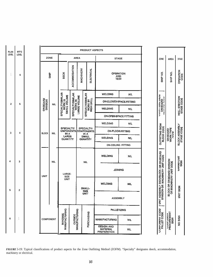
FIGURE 3-19: Typical classifications of product aspects for the Zone Outfitting Method (ZOFM). “Specialty” designates deeck, accommodation,machinery or electrical.

- planning simultaneous execution of many workpackages thus decreasing the overall fitting duration.
Considering these requirements it is practical to plan out-fitting in six manufacturing levels as shown in Figure 3-18.The component, unit and grand unit levels are executed in-dependent of the hull structural zones they will eventually befitted in. The on-block and on-board levels are, of course,entirely dependent on structural entities.
In order to minimize the impact of these dependencies,fitting components should be assembled into units andgrand units as much as possible provided that they are trulyindependent, i.e., rigid and stable without extraordinarytemporary reinforcements or supports. This approach is theprimary means for shortening the durations required for on-block and on-board outfitting.
Within each level other than that for grand units, theresulting proposed interim products are examined forsimilarities in their product aspects. Then, as in the HBCM,they are grouped by similarities in order to:
- further modularize the production process,
- justify expensive but highly efficient facilities, and
- achieve manpower savings.
Typical groupings by product aspects are shown in Figure3-19. Horizontal combinations characterize the various typesof work packages that are requisite and sufficient for thework to be performed for each level. Vertical combinationsof the various work package types denote the process lanesfor outfitting work flow which correspond to those simplyillustrated in Figure 2-4.
As the implementation of ZOFM progresses, the needbecomes greater for balanced planning and scheduling and
cooperation between hull construction, outfitting and paint-ing planners.
3.2.3 Component Procurement
As shown in Figures 3-18 and 3-19, component procure-ment is the initial manufacturing level. It produces interimproducts or zones for outfitting for which no further sub-division is needed by the shipyard. Typical work packagesand material requisitions are grouped by zone and by area toaddress the separate procurement problems, i.e.,
- in-house manufacturing
- outside manufacturing
- purchasing.
These problem areas are - further classified by re-quirements for manufacturing drawings, purchase orderspecifications and raw materials as shown in Figure 3-20.
After having performed groupings by zone, area andsimilarities in component types and sizes, further groupingis made by stage as follows:
- design and material preparation or nil
- manufacturing or nil
- palletizing.
The palletized components are assigned to their respectivework packages for subsequent manufacturing levels.
3.2.4 Unit Assembly and Grand-unit Joining
Just as a block is a key zone for hull construction, a unit isa key zone for outfitting which, as illustrated in Figures 3-18and 3-19, may only require a single manufacturing level.Productivity is enhanced when units are planned which havesimilarities in working hours needed for assembly, numbersof components, volume, weight, design standards, etc.Grouping by such similarities facilitate organizing anduniformly loading process flow lanes.
AREA SUBDIVISIONSAREA
DESIGN TO FURNISH MATERIAL TO BE FURNISHED
IN-HOUSE MANUFACTURINGMANUFACTURING DRAWING
YES
OUTSIDE MANUFACTURINGMANUFACTURING DRAWING YES/NO
PURCHASINGPURCHASE ORDER
SPECIFICATION SELDOM/NO
FIGURE 3-20.’ Problem area subdivisions for design and material preparations. When preparations for outside manufacturing are the same as for in-house, a shipyard retains much control, avoids “vendor” drawing approvals and makes eligible many small firms who do not have design or purchasingdepartments.
36

As indicated in Figure 3-21, unit sizes vary significantly.Therefore two problem areas are designated at the unitassembly level, i.e.:
- large size
- small size.
The distinction is by lift capacity, e.g., units that weighmore or less than one ton. If many small units are plannedfor assembly of larger units, another manufacturing levelmay be included for sub-unit assembly.
Problem areas at the unit level, could be further subdi-vided into:
- machinery unit (machinery combined with all adja-cent components including foundation, pipe pieces,valves, supports, walkways, ladders, etc.)
- pipe unit (no machinery, just pipe pieces combinedwith valves, supports, walkways, etc.), and
- other (hatch covers with coaming, masts, etc.)
Stage for unit assembly is divided as:
- assembly
- welding or nil.
The welding stage applies when extensive or special weldingrequirements exist as welding incident to routine unitassembly is performed by fitters during the precedingassembly stage.
Competitive shipyards have developed machinery unitsinto standard arrangements which are often adapted forvarious types and sizes of ships. As required design andmaterial definition is already available, much planning for astandard machinery unit can progress just as if it was asingle component. A typical standard machinery unit isshown in Figure 3-22. Pipe units are generally uniquebecause they reflect the pipe passages and details peculiar toeach type and/or size Ship even among standard series ships
A variety of units are shown in Figures 3-23 through 3-26.
The grand unit joining level primarily provides for com-bining two or more units in order to:
- reduce the working times needed for fitting on-blockand on-board, and
- produce more stable entities for erection purposes.
5 See Design Modules, Patterns and Panels, and Arrangement Zones in “Outfittional Shipbuilding Research Program, pp 26-33.
6 Pipe assembly problems around machinery are more similar to other machinerycommodation spaces. The great effectiveness of organizing people into design commodation, or machinery, has been proven by the world’s most competitive organizations possesses a mix of pertinent and requisite skills.
37
Classification by area is limited to:
- large size unit or nil
Phasing by stage is:
- joining
- welding or nil.
The welding stage applies only if there are special or exten-sive welding requirements.
3.2.5 On-block Outfitting
Outfitting components, units and grand units aresometimes fitted in a block zone defined for hull construc-tion. However, when they are to be fitted to ceilings, blocksshould be inverted because fitting down hand enhances safe-ty and efficiency. Therefore, the outfit zone for a block setupside down encompasses everything fitted to the ceiling.Following block turnover, the outfit zone encompasses thecomponents, units and/or grand units fitted to the floor.Turnover represents a change in stage. Specifying a zone perstage for each side suffices for absolute control of on-blockoutfitting.
Similarly, outfit items should be fitted in the zone of adouble-bottom block before its tank top panel is installed,Then at a later stage, a different outfit zone encompasseseverything to be fitted to the tanktop. Clearly the primarygoals of this manufacturing level are to outfit ceilings anddouble bottoms when blocks can be manipulated to provideideal access.
Typically, the divisions by area address problems whichare inherently different so that each work package for out-fitting on-block can be assigned to the appropriate team ofassembly specialists for deck, accommodations, machineryor electrical. These classifications are further subdivided bythe quantities of items to be fitted resulting in the followingeight problem area divisions:
- deck: large quantity or small quantity
- accommodation large quantity or small quantity
- machinery: large quantity or small quantity 6
- electrical: large quantity or small quantity.
When the items to be fitted comprise a small quantity perblock, outfit work can be performed at the site where theblock was assembled. When a large quantity is planned, thecompleted block should be transferred to an indoor or out-door region designated for outfitting in accordance with anon-flow concept, i.e., where work packages start and com-plete in unison.
Planning - December 1979” by C. S. Jonson and L. D. Chirillo for the Na-
space assembly problems than they are to problems for assembling pipe in ac-groups, fabrication shops or assembly sections, each specialized for deck, ac-shipbuilders for control of both design and production. Each team within such

HFIGURE 3-21: Unit sizes vary significantly. Top: Engine-room tank-top unit for a 100,000 deadweight-ton diesel-propelled tanker. Bottom /eft: Heat ex-changer, foundations, pipe pieces, etc., incorporated as a unit. Bottom right: The author showing a small unit consisting of pneumatic tubing and sup-ports.
38

39

FIGURE 3-26: A Radar Mast and a Foremast with all components,including electrical, being assembled as units. Zone unit. Arealarge size unit. Stage: assembly. If the masts were hull-constructionblocks, manufactured in-house, the fitting work would have beendesignated on block.
Separation by stage is in accordance with the following se-quence which reflects block turnover:
- on-ceiling fitting
- on-ceiling welding or nil
- on-floor fitting
- on-floor welding or nil.
The welding stages apply only for special or extensivewelding requirements. On-ceiling fitting and welding usuallyis optimum for blocks. However, most on-floor fitting andwelding takes place after on-ceiling outfitting is completed,blocks are turned over, and blocks are joined to creategrand-blocks. In order to simplify the erection schedule andminimize duration in the building dock, such on-floor out-fitting should include all grand units, units and componentsto the maximum extent possible.
Examples of outfitting on-block are shown in Figures3-27 and 3-28.
3.2.6 On-board Outfitting
Outfitting on-board seems at first to be the same as con-ventional outfitting. However, the work required is suscepti-ble to the same analyses as for on-unit and on-block outfit-ting. As a consequence, zone/area/stage control is ap-plicable.
Much outfit work at this level progresses simultaneouslywith hull erection as shown schematically in Figure 2-4.Ideally, outfitting on-board should be limited to:
fitting components, units and/or grand units that aretoo large or too heavy to fit on-block (e.g., mainengines, diesel generators, most units and grand unitsfor engine room tank top, etc.),
fitting fragile and weather-vulnerable componentsthat could be damaged if installed before compart-ments are enclosed (e.g., joinery, insulation, elec-tronic equipment, etc.), and
connecting between components, units and grandunits that are either fitted-on-block or on-board.
One useful method of classifying work packages by prob-lem area simultaneously addresses the teams of specialistsneeded, work volume sizes, and skill requirements inaccordance with the following twelve categories:
- deck: similar work in small volume, high volume, orhigh skill
- accommodation: similar work in small volume, highvolume, or high skill
- machinery similar work in small volume, high volume,or high skill
- electrical similar work in small volume, high volume,or high skill.
Variety work in small volume should be encompassed inan on-board zone for execution by a team having the neededvariety of skills. Variety work in large volume should bedivided by similarities in components and units or sets ofcomponents and/or units. Zones for such problem areasshould not be too long, wide, scattered or otherwise un-favorable for execution and supervision of work. At thesame time planners must regard the need for high-skill fit-ting work required in many ship compartments. In such cases, large zones grouped by specific problem areas couldbe most beneficial.
Stage for on-board outfitting could be divided into:
- open-space (blue sky) fitting
- open-space (blue sky) welding or nil
- closed-space fitting
- closed-space welding or nil.
The welding stages apply only if there is special or extensivewelding to be done. Open-space fitting and welding shouldbe completed before closures imposed by the continuingerection of blocks in order to take full advantage of ideal ac-cess. Therefore, such work shouId be incorporated in theerection schedule. Closed-space fitting and welding activitiesshould be minimized as much as practicable as they require
40

FIGURE 3-27: On-block Outfitting in Pipe Tunnel Below CargoHold.
more working hours, more transportation services, longerdurations, etc.
The on-board outfitting level uses on-board divisons aszones which are subdivisions of the ship as a zone as for theerection level in hull construction work.
3.2.7 Operation and Test
The operation and test level applies to work necessary forassessing the performance of each ship’s functional systems.At this level zone is the entire ship.
Problems are grouped to match teams of specialists forthe following areas:
- deck
- accommodation
- machinery
- electrical.
Further, operation and test is regarded as a single stage.Thus, at this level, work is packaged by one or more systemswithin each of the problem areas defined for the specialistteams. It is the traditional method for planning operationand test work.
41
FIGUIRE 3-28: Engine-room Tank-top Components Fitted On-Block. Sometimes, as in this example, where there is sufficient liftcapacity and reserved time, fitting on-block is just as efficient as fit-ting on-unit.


3.3 Zone Painting Method
The Zone Painting Method (ZPTM) is a natural extensionof the logic employed in both HBCM and ZOFM. Ittransfers much painting work, traditionally performed in abuilding dock or at an outfit pier, to preceding manufactur-ing levels by integrating painting with hull construction andoutfitting processes. Painting is treated as another assembly process that ascends through manufacturing levels astypically shown in Figure 3-29. There are certain prere-quisites for successful application:
- the painting interval between one coat and a next coatmust be shorter than the allowable exposure periodfor the former,
- each hull block should be virtually finished in order tominimize surface preparation and painting reworkcaused by further cutting, fitting and welding, and
- the shop primers applied to plates and shapes should
The main planning objectives for shifting paint relatedwork to the manufacturing levels prior to on-board paintingare to:
- shift positions from overhead to down hand or at theminimum to vertical, from high to low places, andfrom confined to readily accessible places,
- facilitate the use of temperature and humidity con-trolled buildings, especially for sophisticated coatings,
- provide safer environments without extraordinarydevices that would encumber workers,
- prevent in-process rust and associated rework,
- minimize scaffolds needed only for surface prepara-tion and painting, and
- level load work throughout the entire shipbuildingprocess in order to avoid large work volumes in thefinal stages that could jeapordize scheduled delivery.
Typical grouping of paint related work packages by theirproduct aspects are contained in Figure 3-30. Horizontalcombinations characterize the various types of workpackages that are requisite and sufficient for the work to beperformed for each level. Vertical combinations denote theprocess lanes for painting work flow. Obviously, there isneed for balanced planning and scheduling and cooperationbetween hull construction, outfitting and painting planners.Examples of paint systems applied in accordance withZPTM are contained in Figure 3-31.
3.3.1 Shop Primer Painting
This manufacturing level applies to surface preparationfor and application of shop primer to raw materials beforethey are processed to create structural parts or outfit com-ponents. Items which are to be pickled after their manufac-
7 In order to fulfill these prerequisites hull construction, outfitting and paintiprimer and primer levels and between the primer and finish under-coat levels
43
ture are usually excluded. Thus, useful divisions by problemarea are:
- plate
- shapes and other.
The applicable stage categories are:
- shot blasting
- painting.
3.3.2 Primer Painting
This level is for application of an anti-corrosive, includingepoxy and inorganic zinc-silicate, which is the first coat ap-plied to a component or an on-board division (as defined inZOFM), or a block (as defined in HBCM). These constitutethe zone categories.
Problem area is grouped by:
- paint type, i.e., conventional, epoxy, inorganic zinc-silicate, etc.
- number of coats
- type of zone.
The latter further classifies each component, block or on-board division, by problem area to anticipate:
- burn or wear damage of painted surfaces duringHBCM and ZOFM succeeding manufacturing levels,
- difficulty if there is a change in painting conditions,e.g., down hand to overhead, low to high, spacious toconfined, etc., and
- need to maintain appearance.
These considerations again demonstrate that ZPTM, ZOFMand HBCM planning must be coordinated. Painting plan-ners have to consider the foregoing for each zone at allZOFM and HBCM manufacturing levels.
Stage at this level is separated into the following phases:
- surface preparation
- cleaning
- touch UP
- painting
- surface preparation after block turnover or nil
- cleaning after block turnover or nil
- touch up after block turnover or nil
- painting after block turnover or nil.
ng planners have to work together to shorten the durations between the shop. And, managers have to ensure effective accuracy control.

FIGURE 3-29: Typical Manufacturing Levels for the Zone Painting Method (ZPTM).
44

MA
TER
IAL
NIL
PLA
TE
SH
AP
ES
AN
D O
THE
R
CO
MP
ON
EN
T
IU
NIT
TO
BE
FIT
TED
AT
COM
PONE
NT
FITT
ED
ON.
BLO
CKB
LOC
KN
IL
PA
INT
MA
TER
IAL
NU
MB
ER
OF
CO
AT
STY
PE
OF
ZON
E
PA
INTI
NG
ON
-BO
AR
D D
IVIS
ION
PA
INT
MA
TER
IAL
NU
MB
ER
OF
CO
AT
STY
PE
OF
ZON
E/
PA
INT
SC
AFF
OLD
RE
QU
IRE
D O
R N
OT
BO
AR
D O
UTF
ITTI
NG
AT
ON
-BLO
CK
OU
TFIT
TIN
G
PA
INT
MA
TER
IAL
NU
MB
ER
OF
CO
ATS
/TY
PE
OF
ZON
E/
PA
INT
SC
AFF
OLD
RE
QU
IRE
D O
R N
OT
FIN
ISH
UN
DE
R-C
OA
T
ZON
E C
OD
EZO
NE
CO
DE
ZON
E C
OD
EZO
NE
CO
DE
MA
TER
IAL
CO
DE
PA
INT
CO
DE
/P
AIN
T C
OD
E/
PA
INT
CO
DE
/N
UM
BE
R O
F C
OA
TSN
UM
BE
R O
F C
OA
TSN
UM
BE
R O
F C
OA
TS
STA
GE
CO
DE
OF
HB
CM
, ZO
FM, O
R P
PFM

MANUFACTURING LEVEL PAINT SYSTEM A PAINT SYSTEM B
FINISH COLOR COLOR
iFINISH UNDER-COAT
I COLOR I COLORED PRIMER I
PRIMERPRIMER NUMBER OF COATS PRIMER
PER SPECIFICATION
SHOP PRIMER SHOP PRIMER SHOP PRIMER
FIGURE 3-31: Examples of paint systems applied in accordance with the Zone Painting Method (ZPTM). Finish under-coat and finish are not appliedeverywhere, i.e., they are applied only where specified.
1 I
The work at this manufacturing level is coordinated withZOFM so that primer is applied just before the on-ceilingfitting stage and, following bIock turnover, just before theon-floor fitting stage. “Nil” applies to blocks that are notturned over.
3.3.3 Finish Under-coat Painting
This is the semi-final manufacturing level for paint ap-plication. Useful zone classifications are
- components (big in size or which become relatively in-accessible after fitting on-board such as masts, cargobooms, undersides of hatch covers, etc.)
- units which are to be fitted on-board
- outfitted blocks
- on-board divisions
- nil (applicable if epoxy is specified).
Problem area divisions are:
- paint type
- number of coats
- type of zone (as described in Part 3.3.2 for the primerpainting level)
- scaffolding required only for painting or not.
The classification of work packages by stage is the sameas for the primer level.
3.3.4 Finish Painting
Finish painting is the final manufacturing level in ZPTM.Zone, area and stage classifications are the same as in thefinal under-coat level except that:
- stages associated with block turnover are not ap-plicable, and
- “nil” in the final stage “painting or nil” means afinish coat will not be applied, as in the case of epoxy.
46

3.4 integrated Hull Construction, Outfitting & Painting
The zone-oriented methods described in Parts 3.1, 3.2and 3.3, i.e., the:
- Hull Block Construction Method (HBCM),
- Zone Outfitting Method (ZOFM), and
- Zone Painting Method (ZPTM),
were developed from the same logic. But just understandingthe logic and learning application principles are not enough.
FIGURE 3-32: Grand Block, upside down, of Center Deck andCenter Transverse Bulkhead (similar to grand block in Figure 3-10).Temporary staging is fitted to facilitate erection welding. Most of theprimer coat was applied on block before grand-block joining. Aftererection the bottom third will be readily accessible for application ofthe remaining primer coat.
47
There is need for managers, deputy managers and fieIdengineers in assembly organizations who are college trainedor who have otherwise obtained abiIity to think analyticallyabout industrial engineering matters. There is also need forextraordinary leadership to counter the tendency of peopleto favor one type of work at the expense of others.
Integrated HBCM, ZOFM, and ZPTM for a 22,000deadweight-ton multi-purpose cargo carrier, which is notone of a standard series, is illustrated in Figures 3-32through 3-56. Typically, all work shown was performed dur-ing a single 8-hour shift per workday. Sometimes nominalovertime is appIied, usuaIIy for painting.

FIGURE 3-33: Grand Block of Side Shell, Top Side Tank, Transverse Hopper, and Side Transverse Bulkhead of Cargo Hold. Temporary staging is inplace to facilitate erection welding. Primer has been applied to all surfaces except the bottom third which will be readily accessible after erection.
FIGURE 3-34: Same Grand Block as shown in Figure 3-33. The exposed shop primer, limited to the Transverse Hopper surface in this view, is in goodcondition.
48
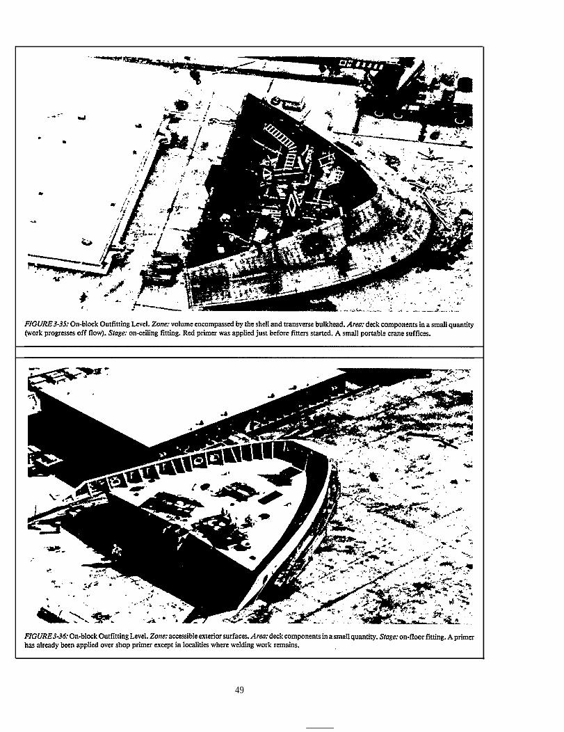
49

50

FIGURE 3-39: On-block Outfitting Level. The right-side block is the same one shown in Figures 3-37 and 3-38. Zone and area are as described in Figure3-37. Stage: on-floor fitting. This on-floor work is progressing next to the building dock. A light crane, of the type used for constructing buildings, is suffi-cient.
FIGURE 3-40: Erecting the outfitted blocks shown in Figures 3-37,3-38 and 3-39. These comprise the Ist Engine-room Flat.
51

FIGURE 3-41: On-block Outfitting Level. Zone: half of a superstructure deck. Area: accommodation components in large quantity (on flow). Stage: on-ceiling fitting. Red primer was applied just before outfitting started.
FIGURE 3-42: On-block Outfitting Level. Zone, area and stage are the same as in Figure 3-41. The block is different.
52

FIGURE 3-43: Grand-block Joining Level. Zone: aft half of superstructure. Area: superstructure. Stage: pre-erection (this designates grand grand-blockjoining).
FIGURE 3-44: Erection Level. Keel laying Plus 11 workdays.
53

I
FIGURE 3-45: Erection Level. Landing the block shown in Figure 3-28. Keel laying plus 13 workdays.
FIGURE 3-46: Erection Level. Engine-room tank-top blocks are erected. Keel laying plus 15 workdays.
54
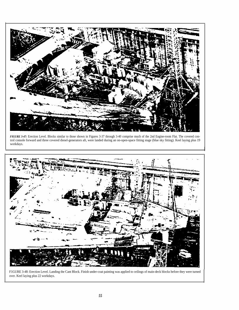
FIGURE 3-47: Erection Level. Blocks similar to those shown in Figures 3-37 through 3-40 comprise much of the 2nd Engine-room Flat. The covered con-trol console forward and three covered diesel-generators aft, were landed during an on-open-space fitting stage (blue sky fitting). Keel laying plus 19workdays.
I
F1GURE 3-48: Erection Level. Landing the Cant Block. Finish under-coat painting was applied to ceilings of main-deck blocks before they were turnedover. Keel laying plus 22 workdays.
55

FIGURE 3-49: Erection Level. Landing the grand block shown in Figures 3-33 and 3-34. Keel laying plus 22 workdays.
FIGURE 3-50: Erection Level. Keel laying plus 24 workdays.
56

FIGURE 3-51: Erection Level. Landing the main engine. Stage: on-open-space fitting (blue sky fitting). Keel laying plus 24 workdays. II
I
FIGURE 3-52: Erection Level. Landing the aft superstructure half (a grand-grand block; see Figure 3-43). Keel laying plus 27 workdays.
57

FIGURE 3-53: Erection Level. Finish paint was applied to the undersides of hatch-covers before the hatch cover/coaming assembly was fitted on-board.Keel plus 28 workdays.
FIGURE 3-54: Erection Level. Aft half of superstructure being lifted. Finish under-coat painting has been completed on all vertical surfaces. Keel plus 29workdays.
58

FIGURE 3-55: Erection Level. Landing the aft half of superstructure on board. As described in Figure 3-43 it is a grand grand-block. Keel PIUS 29workdays.
1 II
FIGURE 3-56: Operation and Test Level. IRON STURT Ship No. 2728, IHI Kure Shipyard. LBP — 163.Om; B — 22.9m; D — 13.6m; d — 10.0m;DWT — 22,093 metric HP — 9000. Start fabrication-18 September 1978; keel laying-5 December launching-9 February (43 workdays in buildingdock; shipyard was closed for 1 January holiday week); delivery 27 April 1979.
59


In I HI shipyards electrical conduit pieces are regarded as pipe Pieces. Tunit, on-block and on-board just as if they were pipe pieces.
4.0 PIPE PIECE FAMILY MANUFACTURING
Just the engine room of a 22,000 deadweight-ton diesel-propelled ship contains about 3,600 pipe pieces. Many dif-ferences among them do not readily disclose commonalitiesthat are useful for planning their manufacture. GroupTechnology (GT) is a philosophy applied by competitiveshipbuilders to systematically classify pipe pieces intogroups or families having design and manufacturing at-tributes which are sufficiently similar to make batchmanufacturing practical. The process is called Pipe PieceFamily Manufacturing (PPFM).
The collection of seemingly different pipe pieces into suchfamilies avoids laborious job-shop type planning, sched-uling and manufacturing. Instead, different pieces within afamily are designated for the same machines and toolingsetups which are arranged in a rationalized process lane. Thebenefits include greater utilization of the same tool setupsand simpler material handling requirements between thework stages in each process lane. The manifestly clear stageby stage progression of developing pipe pieces within suchwork flow lanes greatly enhances production control. Fur-ther, the separation by stages permits the switching of workflow from one process lane to another without diminishingcontrol.
In PPFM the key zone is that which defines a plannedpipe piece. It is an optimum division of a pipe line, usuallyconsisting of:
- cut pipe (including branch when applicable),
- flanges, and/or
- elbows, sleeves, tees, etc.'
A finished pipe piece appears in Figures 3-17 and 3-18 as acomponent, from the “in - house manufacturing” areawithin the lowest ZOFM manufacturing level, needed foroutfitting on unit, on block or on board. Thus, zone forPPFM is different from that for HBCM, ZOFM and ZPTMin that it is not derived from a hull block. Because of thisdifference, PPFM developed independently and is problem-area oriented as distinguished from the zone orientations ofHBCM, ZOFM and ZPTM.
hus
6
A further distinction is that PPFM is a fabrication proc-ess as compared to the assembly processes which character-ize HBCM, ZOFM and ZPTM. Typically, PPFM is appliedin the seven manufacturing levels presented in Figure 4-1.The accompanying product aspects in Figure 4-2 show thatthe most important considerations for grouping proposedpipe pieces by problem area must take into accountsimilarities in:
- material specified (steel, copper, polyvinylchloride,etc.)
- bore size
- shape, i.e., straight or bent
- length
- other factors.
Horizontal combinations of the product aspects charac-terize the various types of work that are requisite and suffi-cient for the work to be performed at each level. Verticalcombinations of the various work package types denote theprocess lanes for pipe-piece manufacturing. Typical areasubdivisions for only the pipe fabrication, pipe pieceassembly and pipe piece joining levels are presented inFigure 4-3.
The work packages, grouped by unique similarities at alllevels facilitate:
- modularization of the fabrication processes, and
- justification for expensive but highly efficientfacilities.
Where applied for either manual or automatic fabricationof the variety of pipe pieces needed for ships, PPFM advan-tages are manifested by:
- less rearrangement of jigs and tools,
- less variations in the work durations and manhours re-quired among the same type work packages,
they are included in PPFM for their manufacture and in ZOFM for outfitting on-
1

FIGURE 4-1: Typical Manufacturing Levels for the Pipe Piece Family Manufacturing Method (PPFM). Note that “Palletizing” is a manufacturinglevel, i.e., each pipe piece is not complete until it is grouped with other required pipe pieces for a specific pallet (zone by area by stage).
62

M'P'GLEVEL LEVEL
1 7
2 6
3 5
4 4
5 3
6 2
7 1
CODES
AREA STAGE
FIGURE 4-2: Typical classifications of product aspects for the Pipe Piece Family Manufacturing Method (PPFM).
63

MATERIAL I X-RAYOR NIL
STEEL
NIL
x-RAY
NONFERROUS
PVC
OTHER
MAIN ORBRANCH
MAIN
BRANCH
BORE I STRAIGHTOR BENT I LENGTH
STRAIGHT
SMALL
BENT
BENT*
STRAIGHTSHORT
LARGELONG**
BENT*
FIGURE 4-3: Problematic subdivisions for Pipe Fabrication, Pipe Piece Assembly, and Pipe Piece Joining Levels only. Blank spaces indicate that nofurther subdivision exists. ● Medium and large bore pipe pieces to be bent can be assigned the same area subdivision. ● *Similarly, long, medium andlarge bore pipe pieces can be assigned the same area subdivision.
MANUFACTURING WORKING HOURS NUMBER OF WORK PACKAGESMETHOD PER WORK PACKAGE P E R W O R K L O T
PPFM PRACTICALLY EQUAL MANY
HBCM VARIABLE ONE
ZOFM VARIABLE ONE
ZPTM VARIABLE ONE
FIGURE 4-4: Differences in Grouping PPFM Work as Compared to Other Manufacturing Methods.

- better accuracy, and
- significant manpower savings.
4.1 Work Lots
It is impractical to control PPFM with one work packageper pipe piece because each is a relatively small job and awide variety and large number of pipe pieces are needed pership. Control by lot, i.e., a group of work packages, is farmore effective provided certain principles are applied.
Within a processing lane the optimum durations requiredfor each work stage and the times required for materialhandling between stages, when summed, yield the overallduration (lead time) required for a processing lane. Thus,minimizing the time required for material handling betweenstages also requires careful attention. Further, the durationsrequired to manufacture all pipe pieces of a particular fami-ly should be equal to each other. These principles permit thegrouping of pipe pieces into a lot, i.e., an ideal mix fromdifferent families that will fully load a facility during adesignated period (work day, work week, etc.). Thus, pipepieces which comprise a lot could be manufactured in anyrandom sequence without diminishing control. A lot shouldbe sized by evaluating its Productivity Value (PV), par-ticularly in consideration of its product resources.2
Figure 4-4 shows the basic differences between workgrouped for PPFM as compared to work grouped forHBCM, ZOFM and ZPTM.
4.2 Material Receiving
Material receiving is the preparation, or first manufactur-ing, level as shown in Figures 4-1 and 4-2. Problem area isgrouped by types of material in accordance with the follow-ing:
- pipe
- flanges, elbows, tees, sleeves, etc.
Stage is simply:
- material receiving.
4.3 Pipe Fabrication
Pipe fabrication, the second manufacturing level, appliesto processing of the pipe only, i.e., processing of the mainpart of the finished pipe-piece zone. Problem area isgrouped by:
- pipe material (steel, non-ferrous, polyvinylchloride,etc.)
- main pipe or branch
- bore (small, medium, or large).
10ne very effective manually operated pipe shop posts a large calendar markepipe piece in process with a color assigned per work lot. Thus, anyone can r
65
These area divisions and further subdivisions are incor-porated in Figure 4-3.
Stages are phased for this level as:
- marking and cutting
- bending of cut pipe or nil
- machining or nil.
Preferably, bending should be deferred for the nextmanufacturing level because it is easier to attach flanges orsleeves to straight pipe. The bending stage at the pipefabrication level is onIy for those exceptional cases whereflanges would lose their required orientations during bend-ing. The machining process applies to the preparation ofpipe ends for welded or threaded joints.
4.4 Pipe Piece AssembIy
At this level flanges, sleeves, etc. are attached to cut pipe.The finished assembly is the zone for a pipe piece except formain and branch subassemblies which are to be joined tocreate a branch pipe piece during the next manufacturinglevel.
Area is subdivided as follows:
- x-ray test or nil
- short straight (5.5 meters or less) or bent
- long straight (over 5.5 meters).
Stage is phased in accordance with the following se-quence
- cut pipe joining or nil
- assembling
- welding or nil
- finishing (grinding or machining) or nil
- bending or nil.
Cut pipe joining is for producing a cut pipe longer than astandard length of 5.5 meters. The welding and finishingstages for main and branch subassemblies are deferred untilafter they are joined to create a branch pipe piece during thenext manufacturing level. Grinding on non-tested pipepieces and machining on pipe pieces to be x-rav tested or onpipe for hydraulic systems, are deferred for accomplishmentduring the next manufacturing level.
d to show a color code assigned to each work week. A dab of paint marks eacheadily determine if the lot in process is on schedule.

4.5 Pipe Piece Joining
The pipe piece joining level is for performing all joiningnot previously accomplished. Typically, it would apply tojoining a main pipe subassembly to a branch pipe subas-sembly or to other parts such as elbows, tees, sleeves, etc.Thus, the pipe pieces finished at this level are neither simpleor straight.
Area is grouped identical to that for the previousmanufacturing level except that the “main or branch” sub-division shown in Figure 4-3 is not required.
Stage is phased as:
- marking and cutting or nil
- joining
- welding
- finishing (grinding or machining).
The marking and cutting stage at this level pertains toboring a hole in a main pipe subassembly as preparation forjoining a branch.
4.6 Testing and Coating
Testing and coating are performed at the places whereeach pipe piece first constitutes a zone. This means placeswhere final work for pipe piece assembly (straight or simple)and pipe piece joining (branches, etc) are performed.
Area for testing is grouped by the different test processesrequired.
Stage is simply:
- testing or nil.
Area for coating is grouped by the different coating proc-esses required.
Stage is phased as:
- pickling or nil
- coating or nil.
4.7 Palletizing
Palletizing is the final manufacturing level and providesfor the sorting of all pipe pieces (including electrical con-duit) in accordance with structured material lists. Each listestablishes the pipe piece requirements for a specific pallet,i.e., the pipe pieces required to outfit on-unit, on-block oron-board during a specific stage.
Problem areas for palletizing are
- deck
- accommodation
- machinery.
Stage is simply
- palletizing.
66

“system" as used for material identification is slightly different from system of the Product Aspmake up a pipeline less machinery items, and anything else omitted for estimating convenience. Sysdesigning and producing and applies to identification in a ship.
67
5.0 PRODUCT RESOURCES
In PWBS, product resources are the inputs to workpackages, each of which can address a specific zone contain-ing portions of a number of systems. Thus, resources aredefined by zone. For the purposes of estimating and earlymaterial procurement, it is also necessary to identifymaterial requirements by systems.
5.1 Material
Material is readily listed-by system from diagrammaticsand also by zone/area/stage from working drawings. How-ever, planning is not complete until each required item isassigned a:
- Material Code Number which designates type, gradesize, etc. (for identification in procurement),
- Material Cost Classification Number which identifiesa particular system and material family (for material-cost control),
- Piece Number which identifies, by unique serialnumber per system, where the item will appear (foridentification in design), and a
. Work Package Number which identifies its end use byzone/area/stage of a specific level of a specific manu-facturing method for a specific ship (for issuecontrol).
Figure 5-1 shows how the foregoing material codes differin their definition content because of differences in:
● Type of work, i.e., hull construction, outfitting orpainting,
● Commonness, e.g., for hull construction, shipbuildinggrade vs. special materials; for outfitting, materialscommonly used in several systems (e.g., piping, access,ventilation or raw materials) vs. materials used only inone system,
Ž Requisition Classification, i.e.:
- Allocated (A) - requisitioned per ship in the exactquantity defined in design,
- Stock (S) - requisitioned for all ships in economicquantities based upon past usage and forecasts offuture needs, and
- Allocated Stock (AS) - requisitioned per ship in thequantity defined in design plus a contingent amountadded in material control based upon a history ofproblems, and
● Standardization, i.e.:
- for hull construction, shipbuilding grade material is ofunique size per sketch (Sketch Size), of a standard sizecommonly used within a specific ship (StandardWithin a Ship), or of standard size generally used inany type ship (Standard).
Regarding Standardzation, any shipbuilding grade plate,angle, etc. for hull construction is sufficiently identified forprocurement by material/grade/size. However, the sameapproach for all other materials would lead to voluminouspurchase specifications. As shown in Figure 5-1 for outfit-ting and painting, materials designated “individual” areidentified one-by-one with an appropriate full descriptionfor each. They are materials generally used in any type ofship. Other materials designated “family” are grouped inorder to relate them by general characteristics. Except fortwo or three traits, a single description identifies allmaterials within a family.
Materials classified as “individual” are defined one-by-one in purchase specifications. Those classified as“family”, are defined family-by-family with unique traitsseparately defined. For example, certain valves are definedby family and their specific sizes and/or design pressures areincorporated in purchase specifications.
Designating system in each outfitting and paintingmaterial code, as shown in Figure 5-1, is useful because itfacilitates standardization in material definition, costclassifications, etc. As also shown, it remains blank forcommon materials until their system designations becomeknown. 1
ects.“System,” for example, includes components whichtem of the Product Aspects includes everything needed for

I
FIGURE 5-1: Identification Codes for Material.
51XX PRIMARYELECT. SOURCE
52XX SECONDARYELECT SOURCE
53XX ELECT.UGHTING &. SIGNAL.
FIGURE 5-2: Typical Structure for Material Cost Classification. Except for Hull Structure, four digits are the system portion of the material codedescribed in Figure 5-1. “XX” of 3rd and 4th digits indicates a family material code.
68

Part and component codes respectively identify hull andoutfit assembly zones which are not further subdivided.Thus, they apply to purchased interim products and thosemanufactured in-house or by a subcontractor.
As shown in Figure 5-1, composition of a Ship PieceNumber for hulI construction is hierarchically configuredas: Ship No./Block Code, Semi-block Code or Sub-blockCode/Part Code. Whenever a specific manufacturing levelis bypassed, its code is not included. Conversely when a partis added as an exception, see Figure 3-11, a Grand-blockJoining Code is incorporated.
The Part Code should at least contain the following infor-mation:
- parent block,
system (bulkhead, deck, longitudinal, etc.), and
unique serial number.
As it facilitates fabrication-shop planning, it is advisable toalso include in the Part Code:
- raw-material type, and
- part shape.
Each Part Code appears in a hull-block parts list, a cut-ting plan and in a subassembly or assembly plan as ap-propriate; see Figure 2-2. Thus, all “what”, “where”,“how” and “when” questions are anticipated by complete-ly defined product aspects, i.e., system/zone/area/stage.
The elements of the Ship Piece Number for outfitting, asshown in Figure 5-1, are: Ship No./System Code/PartNo./Component Code. The System Code combined withthe Component Code, comprise a Material Cost Clas-sification as illustrated in Figure 5-2. The System Code com-bined with a Part No., provide relative positions of pieces(finished interim products only) identified in a systemdiagrammatic. Actual positions of pieces are as shown ineach fitting drawing per zone/area/stage see Figure 2-2.Thus, all questions pertaining to outfitting are also an-ticipated by completely defined product aspects.
The identification codes presented in Figure 5-1 anddescribed in the foregoing, permit each material item to beassigned to both a system-oriented material-control groupand a zone-oriented material-control group. With referenceto Figure 2-1, a work-package number is used for zone-oriented material control during planning, scheduling, exe-cution and evaluation. A material cost classification numbercontrols the same material by system for evaluation,estimating and planning. The combined use of a materialcode and a ship piece number permits transformations fromzone-oriented to system-oriented data and vice versa.
69

TRADES I
ORGANIZATION CODE + PRODUCT ASPECTS/LEVEL = COST CENTER
PRODUCT-ORIENTED WORK BREAKDOWN STRUCTURE
FIGURE 5-3: Typical Cost Centers are separately depicted by the horizontal combinations on each line. Cost centers shown exactly march the shipyardorganization. With few exceptions, the yardsticks used for performance measurement are based upon work packages grouped by problem area per level.Yardsticks are whatever best suits circumstances at each manufacturing level. *ControI by stage is added only when there are special or extensive weldingrequirements. Otherwise, welding incident to normal fitting is performed by fitters; control by problem area is sufficient.
70

5.2 Manpower
In PWBS, manpower is readily assigned by zone, whichpermits immediate association of man-hours allocated withthose charged for manufacturing an interim product. But,reliance on such comparisons for performance measurementis avoided because:
- as there are many work packages, there would be anenormous amount of information generated whichwould obscure significant trends,
- there is a need to provide for both area- and system-oriented work packages in addition to those which arezone-oriented,
- different performance standards, reflecting normalthroughput, are required to separately address evenidentical types of work at different manufacturinglevels, and
an enormous effort would be required to convert“zone- or area-oriented” costs to costs by system asneeded for estimating.
Because of the foregoing, manpower charges are analyzedin accordance with a Cost Center concept derived from theinherent applicability of PWBS to all industrial situations.Manpower charges are identified by:
- Organization Code which indicates the grouping ofworkers by shipyard (in firms that have more thanone), by type of work, by fabrication shop orassembly section, and by trade,
- Badge Number which is a serial number assigned toidentify each worker for payroll purposes only,
- Work Package Number which identifies a manpowerallocation by zone/area/stage for a specific: type ofwork, manufacturing level, and ship, and
- Cost Center Code (Manpower Cost Classification)which identifies the total manpower charges for anumber of work packages grouped per level bysimilarities in select combinations of product aspects(Control Group).
Typical such cost centers, which exactly match a shipyardorganization, are shown in Figure 5-3. They feature primarydependence on collecting manpower charges from a numberof work packages that are separated only by problem areaper manufacturing level. The charges so collected are com-pared to yardsticks for progress and efficiency whichthemselves have been statistically determined from a historyof such charges. Typical yardsticks which are the bases forjudgement during performance evaluations, are shown inFigure 5-4.

5.3 Facilities and Expenses
Facilities and expenses are product resources of a secondorder as compared to material and manpower. The costclassifications and charging methods described in Figure 5-5are commonly applied by many shipyards.
Direct costs are those that can be related to specific in-terim products. Indirect costs are not so identifiable.Therefore, at regular time intervals, forecasts of all indirectcosts to support a group of work packages, e.g., those for amanpower cost-center, are applied as overhead to the costcenter using predicted direct man-hours as the basis for suchapportionments. If there is no difference among appor-tionments, it is prudent to apply a forecast of summarizedoverhead charges to a higher level control group.
72

Achieving the needed work balance is facilitated by adapting zone, area and stage clascreating coordinated schedules for material procurement (including interim products), m
73
6.0 EVALUATION AND FEEDBACK TOESTIMATING
The management cycle, Figure 6-1, incorporates transfor-mations of system- and zone-oriented data in both the plan-ning and evaluation functions. As shown in Figure 2-2, peo-ple who perform design and material deftinition are the p/an-ners who make initial transformations. However, they arevery dependent on feedback from field engineers. This in-teraction between design and production specialists is essen-tial for defining ideal work packages by zone, area and stagethat uniformly load integrated work processes such as thoseshown in Figure 2-4.’
While such zone-oriented work is in-progress, there isneed for evaluation which involves sorting, analyzing andreorganizing performance data collected by control groupsin order to:
- monitor manhours spent, production progress andproductivity, and
- feedback system-oriented data for estimating poten-tial shipbuilding projects.
For these purposes, it is sufficient to address only manpoweramong the product resources. This is because material isidentified both by system and zone, and facilities and ex-penses are charged as overhead on direct material and man-power accounts. Thus, the practical indices shown in Figure5-4, for monitoring man-hours spent, progress and produc-tivity, are sufficient.
6.1 Man-hour Expenditures
The character of the manpower index, i.e., man-hours perunit time, is the same for the various control groups of workpackages which apply to all work categories. Typical ac-cumulations of data recorded accordingly, are provided inFigures 6-2 through 6-5. The plotted curves indicate actualmanpower costs but only apparent progress.
6.2 Production Progress
As shown in Figure 5-4 the indices for production prog-ress use different means of measure (weight, welding
I IFIGURE 6-l: TheManagement Cycle shown applies to any industrialprocess and is annotated with PWBS information flows by system,zone, area and stage. Transformations between system and zone oc-cur in Planning and Evaluation.
sifications (a pallet list) from a previously built ship. This permitsanning, and working drawings very soon after contract award.

parameters, laid cable length, etc.) per unit time. Further, itis sometimes necessary to apply more than one for each con-trol group of work packages. Accumulations of such data asillustrated in Figure 6-6, reflect rea/ progress. When com-pared to pertinent schedules, they are the bases for shortterm adjustments, e.g., shifting workers, using overtime,etc. When the manpower cost-centers exactly match theshipyard organization, as shown in Figure 5-3, it is practicalto delegate such control to the managers of fabricationshops and assembly sections.
6.3 Productivity
Productivity indices, as shown in Figure 5-4, utilize bothmanhours expended and the measures used for monitoringproduction progress, i.e., weight, welding parameters, laidcable length, etc. Typical plots of data so recorded are incor-porated in Figures 6-7 through 6-11 relative to establishedefficiencies. Each of the latter is usually an average basedupon the performance history associated with a specific con-trol group of work packages. Any curve which appearsabove its efficiency reference indicates man-hour expen-ditures at an above average rate.
Productivity evaluations can be simplified by a Productiv-ity-control Group (PCG) concept. It eliminates considerationof specific product aspects and is practical provided:
- each PCG corresponds to a specific manpower-control group, and
- the same indices for manpower expenditures, progressand productivity apply within each manufacturinglevel.
An example of a PCG is illustrated in Figure 6-12. Prod-uct aspects are disregarded because work packages areplanned so that their efficiency values, for normal produc-tivity, fall within a specified allowable range per manufac-turing level.
The PCG concept is another example of inherent versatili-ty in a product-oriented work breakdown. When there areunusual problems (e.g., because of new facilities or over ex-penditures of manpower), more control is applied by usingthe best suited combination of product aspects. Conversely,during routine operations the simpler PCG approach ismore practical.
6.4 Zone to System Transposition
The productivity indices are useful for transposing man-power expenditures for zone-oriented work to the system-by-system data needed for estimating. In PWBS, man-hourexpenditures can be collected by different methods forgrouping work packages depending on the degree of controlrequired. These vary from any combination of trade,manufacturing level, system, zone, area and stage, as shownin Figure 5-3, to a simple Productivity Control Group (PCG)as in Figure 6-12.
Further, there is need to separately address each materialitem for which there is no correlation between its weight andrequired fitting man-hours (e.g., a main engine, boiler,hatch cover, etc.). The fitting of each such “non-parametric” item is the subject of a separate work package.This permits the collection of man-hour expenditures percomponent which is immediately identifiable with a system.
Thus, in consideration of the two sources of zone-oriented data, i.e., parametric and non-parametric man-hours, the total man-hours apportioned to a system can beexpressed by the formulas:
(1) Ht = HP + HC
where
Ht = total man-hours
H P = total parametric man-hours
HC = total non-parametric man-hours
e = a productivity index for a control group Ofwork packages
v = pertinent description of that part of a systemincluded in a control group of work packages, e.g.,assembly weight, length of weld, manufacturedpieces, parametric-component weight, laid cable
i = the number of work-package control groups inwhich a system is represented
where
h = man-hours for fitting a non-parametric com-ponent
j = the number of non-parametric components
74

FIGURE 6-2: Manpower Expenditures-Hull Construction.
FIGURE 6-4: Manpower Expenditures-Electrical Assembly of AllComponents Except Cable.
FIGURE 6-6: Production Progress-Hull Construction.
FIGURE 6-3: Manpower Expenditures-Msvhinery Fitting.
I
FIGURE 6-5: Manpower Expenditures-Electrcal Assembly ofCable.
FIGURE 6-7: Productivity-Parts Fabrication. The plot for bendingis by stage. The other two are by problem area. This illustrates theversatility of PWBS for fulfilling practical needs.

WEIGHT
FIGURE 6-8: Productivity-subassembly and Block Assembly. Thecurved-block and flat-block plots are by problem area. Thesubassembly plot is by level.
FIGURE 6-10: Productivity-Machinery Fitting. Parametric-component weight is the weight of only those items for which thereare correlations between weight and fitting man-hours.
FIGURE 6-9: Productivity-Erection. In this special case the pro- ducdvity index, man hours/fabricated weight, is used to establish a
reference because weight accumulates rapidly as block are landed andwelding mart-hours lag. Managers employ the reference to monitoroutstanding welding man-hours relative to landed weight.
FIGURE 6-11: Producdvity-Electrial Fitting of all components ex-cept cable. Each work package identities total weight and parametric-component weight. The difference, i.e., items which comprise non-parametric-component weight, are treated as exceptions.
FIGURE 6-12: The Productivity-control Group (PCG) Concept as applied to Machinery Fitting. This example corresponds to a specific manpower-control group in Figure 5-3 (i.e., all elements of the Organization Code less trades). Regardless of product aspects, each work package efficiency ratingfalls within an allowable range specified for each manufacturing level. If normal performance causes overlap, such as is possible for on-unit and on-blockefficiencies, there is no need to address them as separate PCG.

"Improving Shipyard production with Standard Components and Modules” by Y. Ichinose, IHI Meeting, April 26, 1978, pp. 10-1 to 10-11.
77
7.0 PRACTICAL SUGGESTIONS
PWBS facilitates the accumulation of experiences in a se-quence of work packages which addresses specific interimproducts. Interim products for a subsequent ship-construction project, are matched to their predecessors byzone/are/stage in order to apply pertinent experiencesregardless of differences in design details. Thus, a workpackage with a modest goal, e.g., a small assembly of outfitcomponents, can be significantly improved in productivityvalue over just a few ship construction projects. This proc-ess of continuing improvement is dependent upon thereorientation of managers and workers and in particularupon the interaction of designers and field engineers. Thefollowing suggestions, by functions, are intended to assist inimplementation of PWBS.
7.1 Sizing Work Packager
7.1.1 Quality
As described in Part 1.3 herein, quality (Q) is a fun-damental element for determining the productivity value(PV) and hence size of a work package. In addition toevaluating the impact of specified accuracy or functioningability of an interim product, it also assesses the safety andefficiency of related work.
For HBCM work, Q evaluations should be made duringtransition design. Ideal division of a hull into blocks shouldresult in:
- minimal welding during erection,
. stable blocks that facilitate erection,
- block and part shapes that, as much as possible, arestandard within each hull and facilitate outfitting andpainting.
Fulfillment of these objectives in planning results in thesafest and most efficient work circumstances in production.
The Q for ZOFM work packages is considerably depen-dent upon hull structure. Therefore, extraordinary coor-dination is required during transition design so that outfitwork specialists who establish the system/zone interrelation-ships on composites can:
- for zone considerations arrange components tofacilitate the progress of outfit work zone-by-zone andgroup-by-group; gather and lay pipe pieces and elec-tric cables in orderly pipe and cable passages respec-tively locate pipe line joints for connecting betweenblocks, on the same deck or flat;
- for area considerations group components in order tocoordinate the start of work for machinery founda-tions, machinery, pipe supports, pipe pieces, walk-ways, etc.;
- for stage considerations phase components to reduceoverhead work by fitting on-ceiling with blocks turnedover and to reduce services required during on-open-space fitting of large components; and
- incorporate modularized work packages and workpackage components as much as possible.’
7.1.2 Quantity
As described in Part 1.3 herein, quantity (N) is an in-dicator of the amount of all resources required for a workpackage. However, of the resources, material and man-power quantities are the principal N determinents.
The number of components for a work package should belimited to that which a worker can quickly sort and fit at adesignated site. Otherwise, a disproportionate amount ofthe working time allocated is used to find needed com-ponents. Work packages which contain large componentscan be sized by weight.
CO., Ltd., Tokyo: proceedings of the SNAME Spring

Manpower should be allocated by considering skill levelsof workers and their assistants and the work volume in-volved. It is sometimes necessary to add manpower in orderto reduce planned working time.
7.1.3 Time
As stated in Part 1.3 herein, time (T) is the durationalIowed for accomplishment of a work package; it is work-ing time. It is a key element for scheduling. Work packages,insofar as possible, should be organized for accomplishmentwithin modularized time spans, e.g., within five or ten days.This facilitates scheduling of work package starts and com-pletions in unison as is required for on-flow work. Dura-tions achievable are dependent upon Q, N and workers’abilities and degrees of persistency.
7.2 Design and Material Definition
7.2.1 Hull Construction
(1) Zone-oriented block plans and corresponding blockparts lists should be prepared as intermediate plans fortransforming from system-oriented functional plans(e.g., midship section, and shell expansion) to work-ing drawings by zone/area/stage (i.e., cutting, subas-sembly and assembly drawings).
(2) Hull block planning should be performed in coopera-tion with field engineers to facilitate outfitting andpainting as welI as hull construction.
(3) Block and part coding shouId be made block-by-blockto facilitate coordinated scheduling of work packagestart dates and collection and sorting of parts andsubassemblies. That is, all cutting, subassembly andassembly plans should be sequenced to anticipate theblock assembly master schedule. This measure isnecessary to avoid producing parts and subassembliestoo far in advance. Items which are produced early,generally identical parts or subassemblies, create needfor more storage space and problems associated withretrieval, non-uniform lead times, deteriorating shop-primer, etc. Further, the inconsistent groupingdetracts from clear understanding of the productionprocess grouped by area and stage which is necessaryfor layout of smooth operating process lanes.
(4) A block plan should apply to a group of adjacentblocks and shouId be organized as a compact bookletwhich includes necessary work instructions.
(5) Assembly, subassembly and cutting working drawingsshould be prepared by zone/area/stage. These shouldreflect the work instructions written in the block plan.
(6) During marking, if parts for a specific block or forbIocks once or twice removed in a schedule do not oc-cupy all of a plate, the cutting plan should devote theexcess material to flat-bar for stock rather than toparts needed far in advance.
(7) The drawing issue schedule should be establishedblock-by-block and be in accordance with the bloclassembly master schedule.
7.2.2 0utfitting
(1) Using diagrammatic, all material requirementshould be defined by system to facilitate sorting anearly identification of long-lead time, manufacturingorder and short-lead time materials.
(2) Zone-oriented drawings (composites) should beprepared as intermediate drawings for transposingfrom system-oriented diagrammatic to work instructions drawings. The composites need only showenough detail to establish the system and zone interrelationships.
(3) The arrangements on composites should anticipate basic scheme for zone/area/stage, i.e., a pallet list fowhich there has been agreement between designer:and production engineers in the field.
(4) A composite drawing should apply to a group of adjacent zones and even overlapping zones provided thelatter are planned for different stages.
(5) Planning for outfit work packages, grouped byzone/area/stage, should be integrated with hull blockplanning.
(6) Work instruction drawings should include details forall pipe lines excepting only short tubing lengths forinstruments.
(7) Codes for outfit work packages and componentsshould incorporate zone-by-zone identifications inorder to facilitate coordinated scheduling of workpackage start dates and collection and sorting of outfitcomponents.
(8) Each work package should be clearly identified bzone/area/stage on a work instruction drawing anprovided with a specific material list of fittings. Sucdrawings developed from composites (often by tracing) should provide information, commensurate witworkers’ comprehension levels, such as:
- when, relative to other interim products shouldspecific interim product be assembled,
- what components it is to be produced from,
- how is it to be assembled, etc.
These instructions are important. They must be continuously updated based upon feedback from workerand field engineers to detail designers. They are meanfor an organization to retain useful work experiencerather than allowing experience to be just vested in in-dividuals. Also, the instructions are needed to ade-quately control work flow on process lanes. Workpackages classified by the work problems they impose
78

are matched to sets of solutions which include specificworker qualification classes. This avoids need toassign the same individuals who produced identical in-terim products in the past. The absence of this ar-bitrary restriction facilitates scheduling for processflow lanes so that they are more uniformly loaded andbetter coordinated with each other.
7.3 Material Procurement and Control
7.3.1 Hull Material
(1) Lists for raw materials should be prepared from roughcutting plans for hull structural parts based uponreference to functional plans. Thus, commitment andsystematic deliveries for maintenance of a minimumsupply in the shipyard can be arranged at a very earlystage.
(2) Lists for raw materials should be reprepared fromdetail cutting Plans based upon reference to the block
7.3.2
(1)
(2)
plan. These lists should be used to control materialissues.
Outfit Material
Each component, except minor common items freelyavailable in bins near work sites, should be coded bypiece and work package. The coding is essential inorder to identify:
- when specific material requisition orders should bereleased,
- when material should be delivered to work sites, and
- what fittings must be collected to fulfill a workpackage material list (MLF).
Each component should be painted at least throughthe primer level (if required) and identified with itscode number (painted or tagged) by its in-house orsubcontractor manufacturer before it is sent to theshipyard’s warehouse.
(3) Fittings should not be issued separately to workerscalling at the warehouse. They should only becomeavailable to workers in a collection of materials(pallet) delivered at a specified time and place for ex-ecution of a specific work package.
(4) Starting as early as the beginning of basic designthrough completion of palletizing, lead times for fit-tings must be considered by everyone concerned withmaterial definition, procurement, manufacturingwarehousing and palletizing.
7.4 Producing
7.4.1 Hull Construction
(1) Field engineers should have contributed to hull blockplanning in order to insure that designers anticipatedthe capabilities and limits of available manpower and
79
facilities, and worker safety requirements. Such inputshould be based upon experience at work sites.
(2) In accordance with the PWBS concept, workpackages should be organized to achieve coordinatedwork flows on specific process lanes as illustrated inFigure 2-4.
(3) Standards are required for accuracy control of theseparate flow lanes in accordance with consistent cri-teria. This insures that the end products of differentwork stages will ultimately fit together easily becausetheir dimensions are within allowed tolerances basedon a common scheme. Thus, a system for accuracycontrol is essential for maintaining scheduled workflows.
(4) In a process lane, both the safety and quality of workcircumstances for a specific work stage should be fre-quently evaluated and always in the context of thework stages immediately before and after.
(5) Systematic in-process material control and associated
7.4.2
(1)
(2)
(3)
(4)
time are required between successive work processesfor collecting, sorting and distributing interim prod-ucts (especially small end products after fabricationand sub-block assembly processes).
Outfitting
Outfit work package planning and classificationsshould be proposed by production field engineers todetail designers for incorporation on composites andwork instruction drawings.
Work package planning should reflect a pallet list andthe PWBS concept as typically portrayed in Figure2-4. In other words each work package should addressa zone by stage and be classified by similarities inwork problems.
On-unit and on-block outfitting should be planned foraccomplishment on sites adjacent to the erection site
in order to avoid transportation problems immediate-ly before erection.
The on-unit, on-block and on-board outfitting masterschedules should reflect the block erection and blockassembly master schedules. Careful coordination is re-quired with other functions (e.g. design, material pro-curement, hull construction, painting) for such con-cerns as:
- time reservations for necessary outfitting on-blockbefore a block is completed,
- needed lead times for design, material definition,procurement and fabrication.
(5) Work instruction drawings grouped by zone/area/-stage should be prepared for outfit workers’ conven-ience even at some added expense in design.
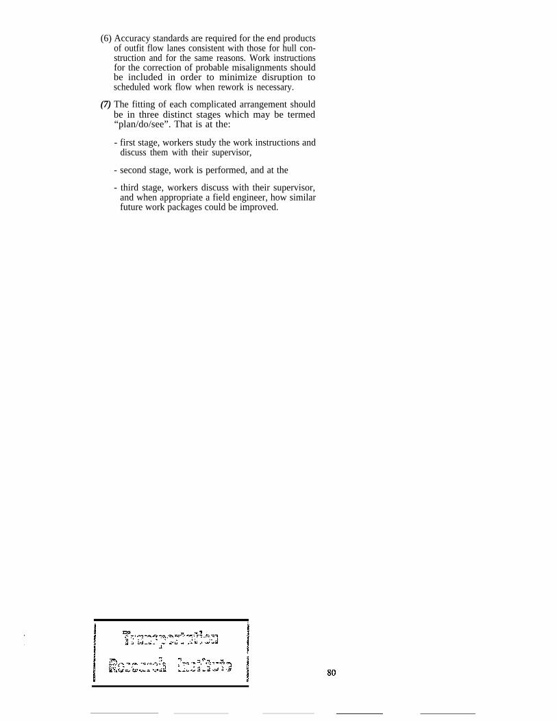
(6) Accuracy standards are required for the end productsof outfit flow lanes consistent with those for hull con-struction and for the same reasons. Work instructionsfor the correction of probable misalignments shouldbe included in order to minimize disruption toscheduled work flow when rework is necessary.
(7) The fitting of each complicated arrangement shouldbe in three distinct stages which may be termed“plan/do/see”. That is at the:
- first stage, workers study the work instructions anddiscuss them with their supervisor,
- second stage, work is performed, and at the
- third stage, workers discuss with their supervisor,and when appropriate a field engineer, how similarfuture work packages could be improved.
, ft1