Marine Roof - techwebasto.com · Marine Roof Marinedach ... dome or round head for rear rails...
24
Marine Roof Marinedach Toit ouvrant Marine Marine schuifdak Installation Instructions Einbauanweisung Instructions de montage Montagehandleiding Einbauanleitung Instructions de montage 80 Series 80er Serie Série 80 80 Series
Transcript of Marine Roof - techwebasto.com · Marine Roof Marinedach ... dome or round head for rear rails...
Marine RoofMarinedachToit ouvrant MarineMarine schuifdak
Installation InstructionsEinbauanweisungInstructions de montageMontagehandleidingEinbauanleitungInstructions de montage
80 Series80er SerieSérie 8080 Series
80 Series
TABLE OF CONTENTS / INHALTSVERZEICHIS / INDEX / INHOUDSOPGAVE
English ................................................................................................................................ 3
1. INTRODUCTION............................................................................................... 52. OPERATION..................................................................................................... 53. PRE-INSTALLATION ........................................................................................ 64. SEAL COMPRESSION ................................................................................... 115. INSTALLATION ............................................................................................. 126. ELECTRICAL CONNECTIONS ........................................................................ 157. RESETTING .................................................................................................. 168. ELECTRICAL DIAGRAM ................................................................................ 179. SAFETY ....................................................................................................... 1810. SUPPORT....................................................................................................... 1911. TECHNICAL DATA......................................................................................... 1912. CHECKLIST.................................................................................................... 21
Deutsch.................................................................................................................................
Français .................................................................................................................................
Nederlands ............................................................................................................................
80 Series
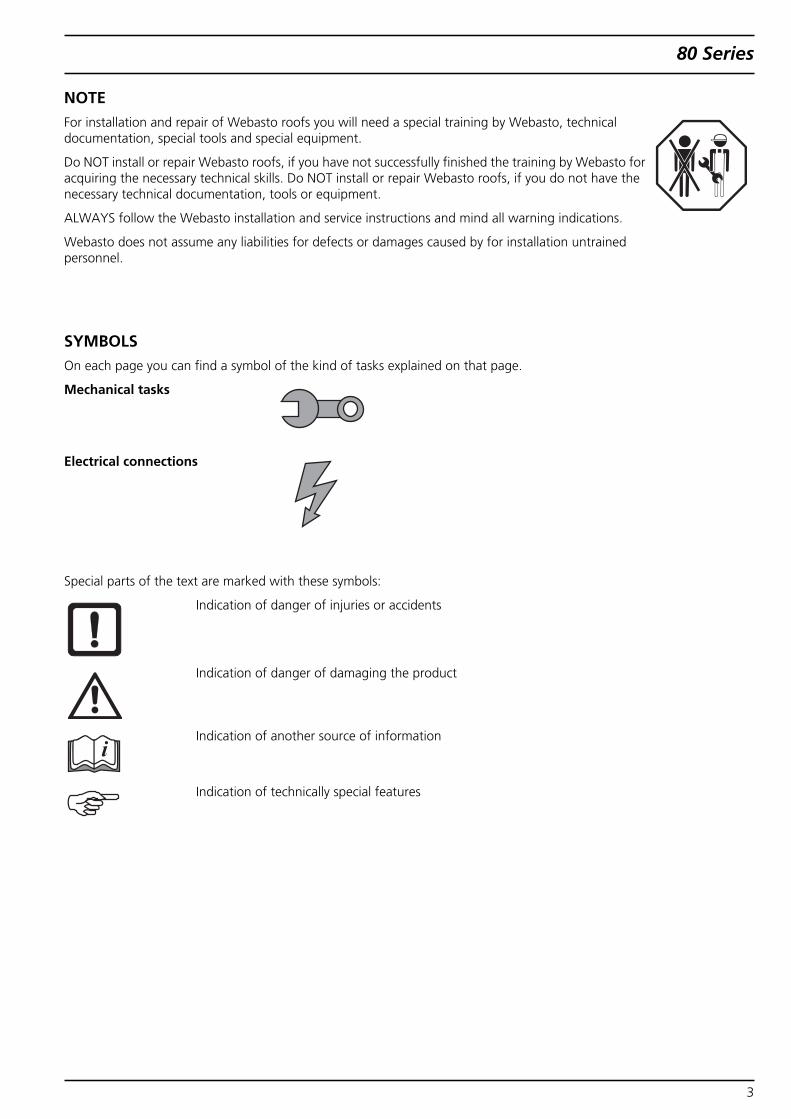
NOTEFor installation and repair of Webasto roofs you will need a special training by Webasto, technicaldocumentation, special tools and special equipment.
Do NOT install or repair Webasto roofs, if you have not successfully finished the training by Webasto foracquiring the necessary technical skills. Do NOT install or repair Webasto roofs, if you do not have thenecessary technical documentation, tools or equipment.
ALWAYS follow the Webasto installation and service instructions and mind all warning indications.
Webasto does not assume any liabilities for defects or damages caused by for installation untrainedpersonnel.
SYMBOLSOn each page you can find a symbol of the kind of tasks explained on that page.
Mechanical tasks
Electrical connections
Special parts of the text are marked with these symbols:
Indication of danger of injuries or accidents
Indication of danger of damaging the product
Indication of another source of information
Indication of technically special features
3
80 Series
SCOPE OF DELIVERY• Top frame (incl. 2 motors, mechanisms, wiring, rocker switch)
• Hinge bodies, left and right (incl. sliding mechanism)
• Rear rails, 2 pcs
• Rear rail covers, 2 pcs
• Rear rail end caps, 2 pcs
• Emergency key (hex key), 2 pcs
• Installation instructions
• Installation instructions
• Operating instructions
• Panel assembly (according your order)
OTHER MATERIALS REQUIRED• Hardware to fix top frame and rear rails: screws stainless steel A4, class 70
- M5 pan, dome or round head for rear rails (alternative: self tapping screws)- M6 pan, dome or round head for rear rails (alternative: self tapping screws)
• Hardware to fix panel to hinge bodies and lever assemblies: screws stainless steel A4, class 70
• High quality, acid-free, UV resistant, silicon mastic sealant
• Loctite® 243 or similar thread sealant
• Grease Isoflex® Topas L32
• Fuse 40 A
• Electrical wiring, connectors, etc.
NECESSARY TOOLS• Drilling machine
• Drills ø 4.2 and 5 mm
• Taps M5 and M6
• Hex keys
• Mastic gun
• Screwdrivers
• Tools for electrical connections
PersonnelPerform roof installation with at least 2 persons. This makes the installation easier and reduces the risk of damage.
ProtectionImproper use of tools can lead to injuries or damage to the ship or roof!Thoroughly read tool instructions prior to using.Before using any specialized tools, make sure to know all rules and regulations in your country.Cover interior and exterior of the ship with protection materials (covers, cloths, etc.) to reduce the risk of damage.Also wear protective clothing like ear protection, safety shoes, safety goggles and protective gloves.
4
80 Series
1. INTRODUCTIONThe Webasto 80 Series is an electrically operated sliding roof for comfort purposes. The sliding roof has been designed foruse on motor and sailing yachts and can be used in the toughest conditions.
It is suitable for fitting in area III (or area II, depending on your order) and usage for ship type with design-category A (ocean-worthy).
All parts are made from high corrosion resistant materials.
Note: Several components are customer specific and may be different from corresponding componentsshown in this document.
2. OPERATIONSee operating instructions.
5

80 Series
3. PRE-INSTALLATION
Marine Roof has to be installed on surface withshape specified below.
Deck must be sufficiently strong at installation point.If not, reinforcement must be made.
Note:Illustration is an example!
Deck shape:
- Lengthwise: uncurved, straight.
- Cross direction: According your order.
- Place top frame in deck.
- Center top frame in aperture.
- Fixate top frame to deck near “A”
• Aluminium or steel deck:
Drill hole ø 4.2 mm and cut thread M5.
Important:Do not damage seal when drilling holes,placing and tightening fixing screws.
• Other deck materials, e.g. GRP (Glass Ren-forced Plastic):
Make your own choice.
- Check if boat center and rear beam of top frameare perpendicular.
- Fixate top frame to deck near “B”,same as before (near “A”).
- Check if sides of top frame and parallel andperpendicular to rear beam.
- Fix top frame to deck near “C” and “D”,same as before (near “B” and “A”).
- Check if sides of top frame are parallel andperpendicular to rear beam.
R2R1
R3
W2 L2L1
A
A
B
C
D
6
80 Series
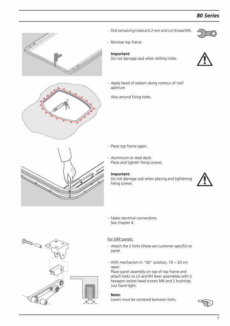
- Drill remaining holes ø 4.2 mm and cut thread M5.
- Remove top frame.
Important:Do not damage seal when drilling holes.
- Apply bead of sealant along contour of roofaperture.
Also around fixing holes.
- Place top frame again.
- Aluminium or steel deck:Place and tighten fixing screws.
Important:Do not damage seal when placing and tighteningfixing screws.
- Make electrical connections.See chapter 6.
For GRP panels:
- Attach the 2 forks (these are customer specific) topanel.
- With mechanism in “tilt” position, 10 ~ 20 cmopen:Place panel assembly on top of top frame andattach forks to LH and RH lever assemblies with 2hexagon socket head screws M6 and 2 bushings.Just hand-tight.
Note:Levers must be centered between forks.x x
7
80 Series
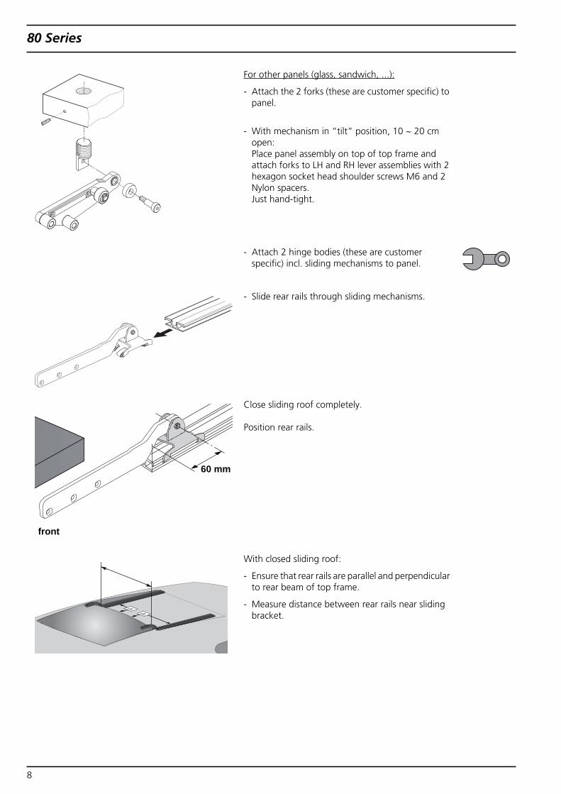
For other panels (glass, sandwich, ...):
- Attach the 2 forks (these are customer specific) topanel.
- With mechanism in “tilt” position, 10 ~ 20 cmopen:Place panel assembly on top of top frame andattach forks to LH and RH lever assemblies with 2hexagon socket head shoulder screws M6 and 2Nylon spacers.Just hand-tight.
- Attach 2 hinge bodies (these are customerspecific) incl. sliding mechanisms to panel.
- Slide rear rails through sliding mechanisms.
Close sliding roof completely.
Position rear rails.
With closed sliding roof:
- Ensure that rear rails are parallel and perpendicularto rear beam of top frame.
- Measure distance between rear rails near slidingbracket.
60 mm
front
8
80 Series
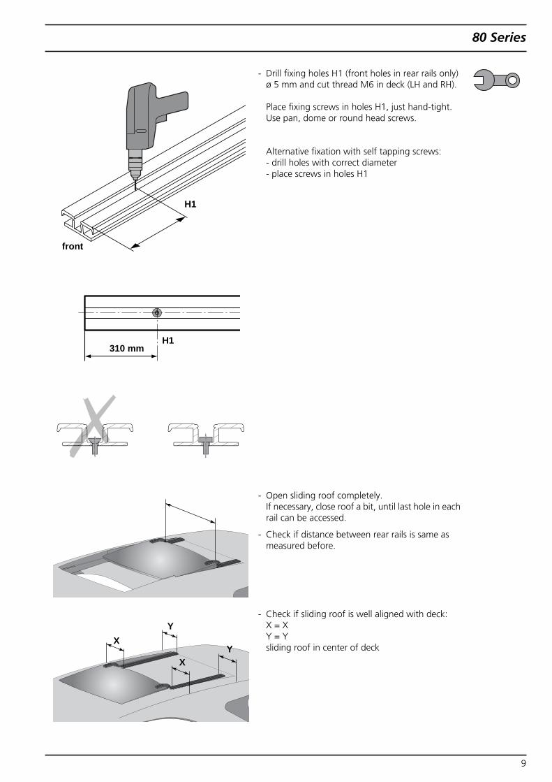
- Drill fixing holes H1 (front holes in rear rails only)ø 5 mm and cut thread M6 in deck (LH and RH).
Place fixing screws in holes H1, just hand-tight.Use pan, dome or round head screws.
Alternative fixation with self tapping screws:- drill holes with correct diameter- place screws in holes H1
- Open sliding roof completely.If necessary, close roof a bit, until last hole in eachrail can be accessed.
- Check if distance between rear rails is same asmeasured before.
- Check if sliding roof is well aligned with deck:X = XY = Ysliding roof in center of deck
H1
H1
front
310 mm
YX
YX
9
80 Series
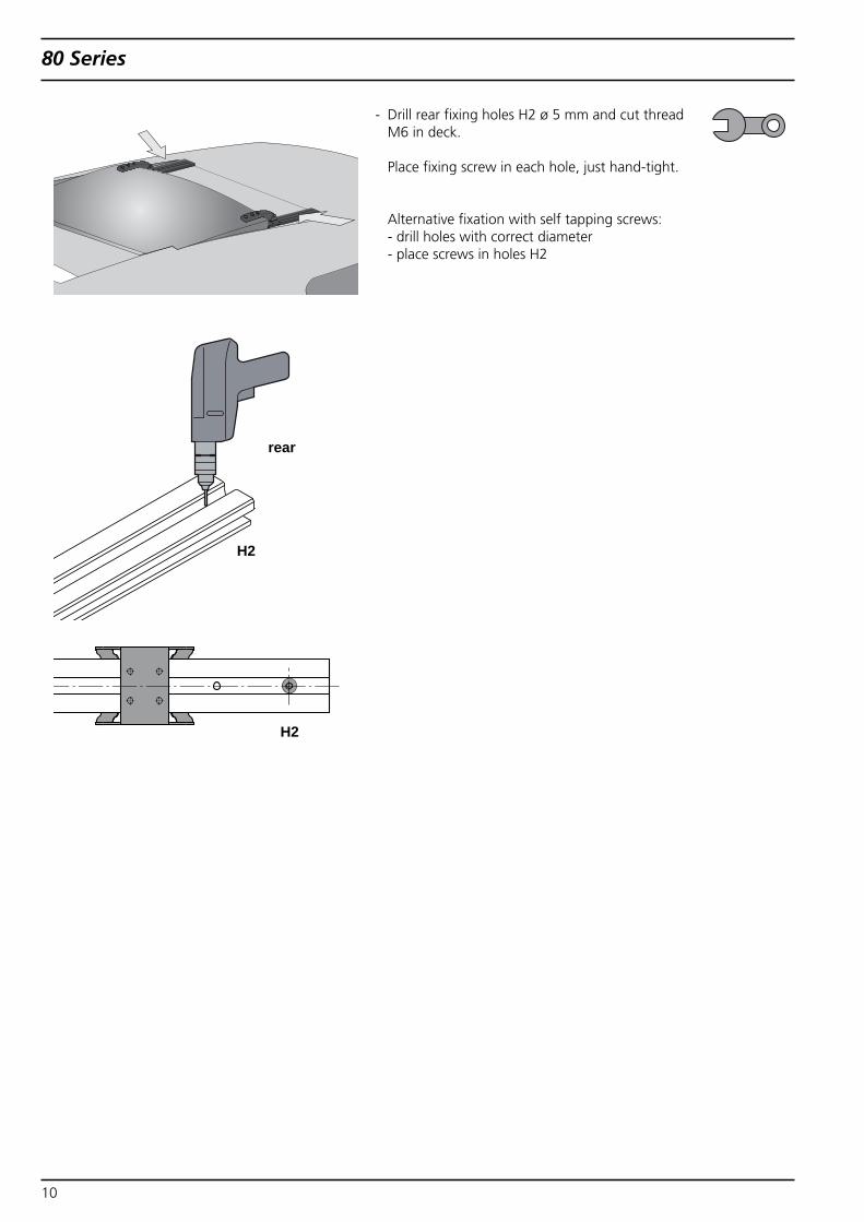
- Drill rear fixing holes H2 ø 5 mm and cut threadM6 in deck.
Place fixing screw in each hole, just hand-tight.
Alternative fixation with self tapping screws:- drill holes with correct diameter- place screws in holes H2
H2
H2
rear
10
80 Series
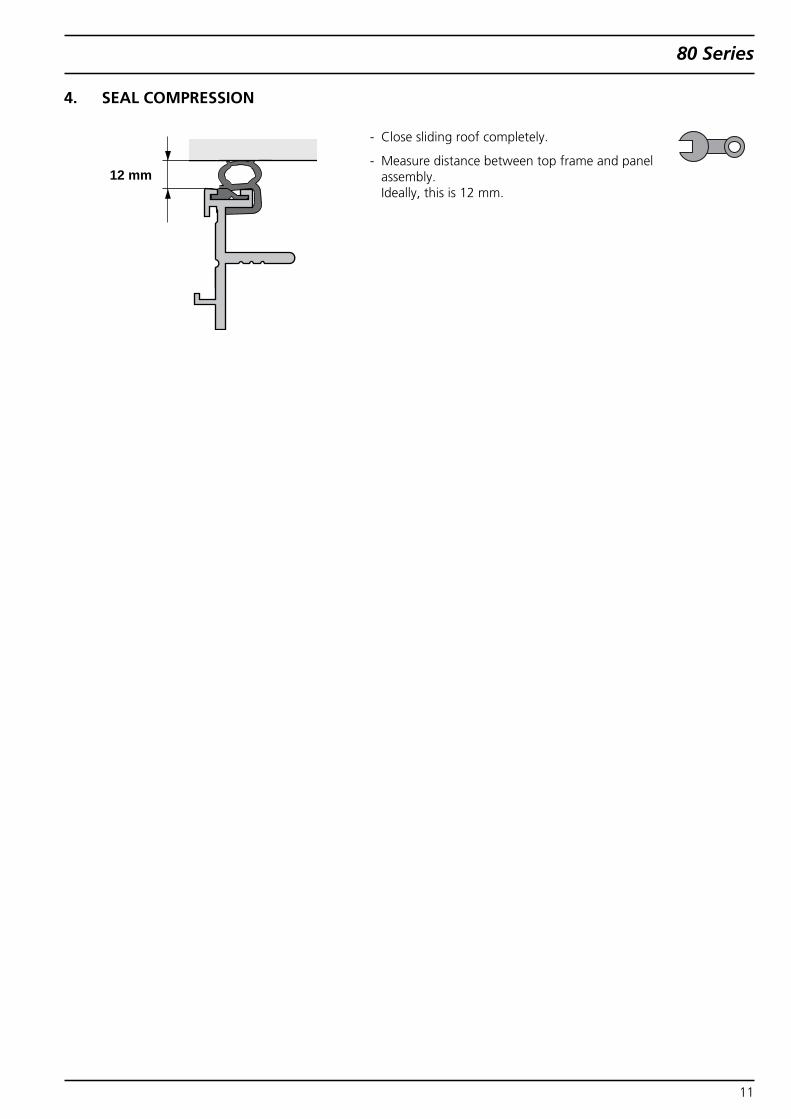
4. SEAL COMPRESSION
- Close sliding roof completely.
- Measure distance between top frame and panelassembly.Ideally, this is 12 mm.
12 mm
11
80 Series
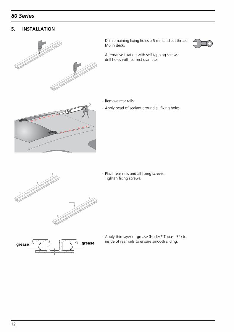
5. INSTALLATION
- Drill remaining fixing holes ø 5 mm and cut threadM6 in deck.
Alternative fixation with self tapping screws:drill holes with correct diameter
- Remove rear rails.
- Apply bead of sealant around all fixing holes.
- Place rear rails and all fixing screws.Tighten fixing screws.
- Apply thin layer of grease (Isoflex® Topas L32) toinside of rear rails to ensure smooth sliding.greasegrease
12
80 Series
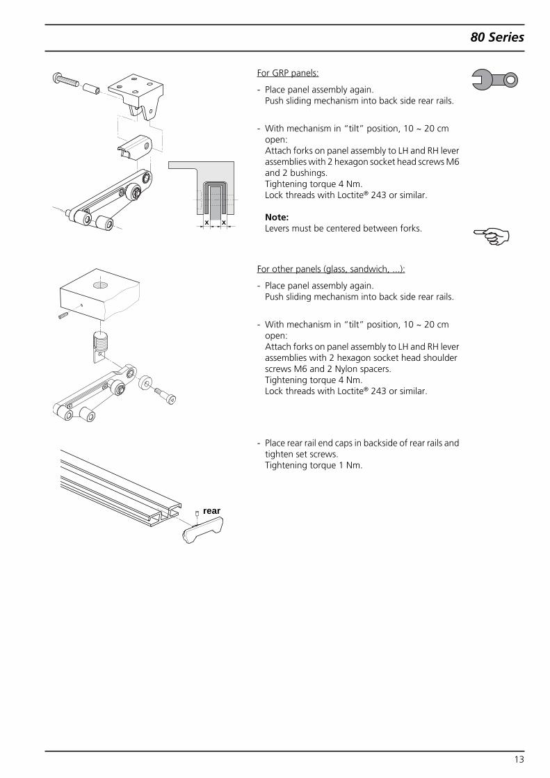
For GRP panels:
- Place panel assembly again.Push sliding mechanism into back side rear rails.
- With mechanism in “tilt” position, 10 ~ 20 cmopen:Attach forks on panel assembly to LH and RH leverassemblies with 2 hexagon socket head screws M6and 2 bushings.Tightening torque 4 Nm.Lock threads with Loctite® 243 or similar.
Note:Levers must be centered between forks.
For other panels (glass, sandwich, ...):
- Place panel assembly again.Push sliding mechanism into back side rear rails.
- With mechanism in “tilt” position, 10 ~ 20 cmopen:Attach forks on panel assembly to LH and RH leverassemblies with 2 hexagon socket head shoulderscrews M6 and 2 Nylon spacers.Tightening torque 4 Nm.Lock threads with Loctite® 243 or similar.
- Place rear rail end caps in backside of rear rails andtighten set screws.Tightening torque 1 Nm.
x x
rear
13
80 Series
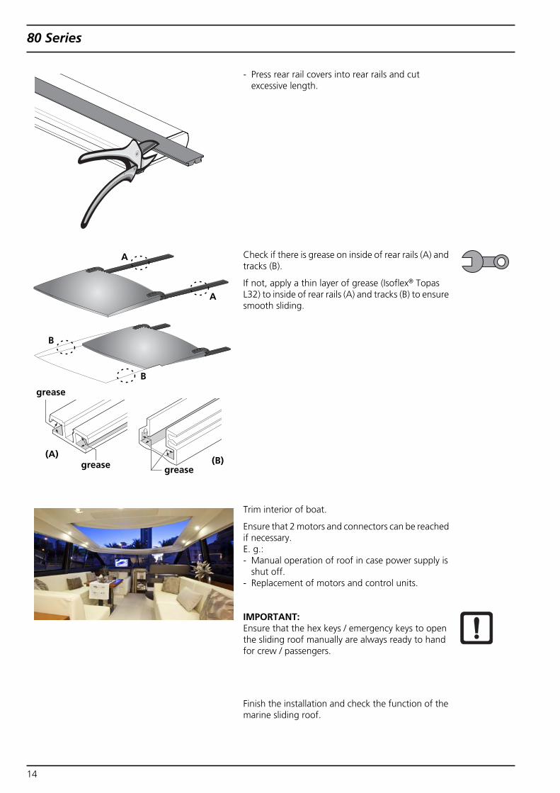
- Press rear rail covers into rear rails and cutexcessive length.
Check if there is grease on inside of rear rails (A) andtracks (B).
If not, apply a thin layer of grease (Isoflex® TopasL32) to inside of rear rails (A) and tracks (B) to ensuresmooth sliding.
Trim interior of boat.
Ensure that 2 motors and connectors can be reachedif necessary.E. g.:- Manual operation of roof in case power supply is
shut off.- Replacement of motors and control units.
IMPORTANT:Ensure that the hex keys / emergency keys to openthe sliding roof manually are always ready to handfor crew / passengers.
Finish the installation and check the function of themarine sliding roof.
A
A
B
B
grease
grease
(A)
grease(B)
14
80 Series
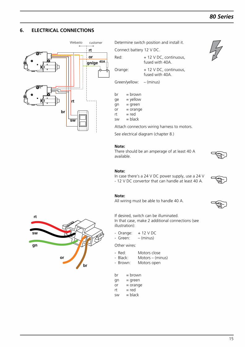
6. ELECTRICAL CONNECTIONS
Determine switch position and install it.
Connect battery 12 V DC.
Red: + 12 V DC, continuous,fused with 40A.
Orange: + 12 V DC, continuous,fused with 40A.
Green/yellow: – (minus)
br = brownge = yellowgn = greenor = orangert = redsw = black
Attach connectors wiring harness to motors.
See electrical diagram (chapter 8.)
Note:There should be an amperage of at least 40 Aavailable.
Note:In case there’s a 24 V DC power supply, use a 24 V- 12 V DC convertor that can handle at least 40 A.
Note:All wiring must be able to handle 40 A.
If desired, switch can be illuminated.In that case, make 2 additional connections (seeillustration):
- Orange: + 12 V DC- Green: – (minus)
Other wires:
- Red: Motors close- Black: Motors – (minus)- Brown: Motors open
br = browngn = greenor = orangert = redsw = black
rtor
gn/ge
rt
sw
br
40A
sw
gn
or
rt
br
customerWebasto
15
80 Series
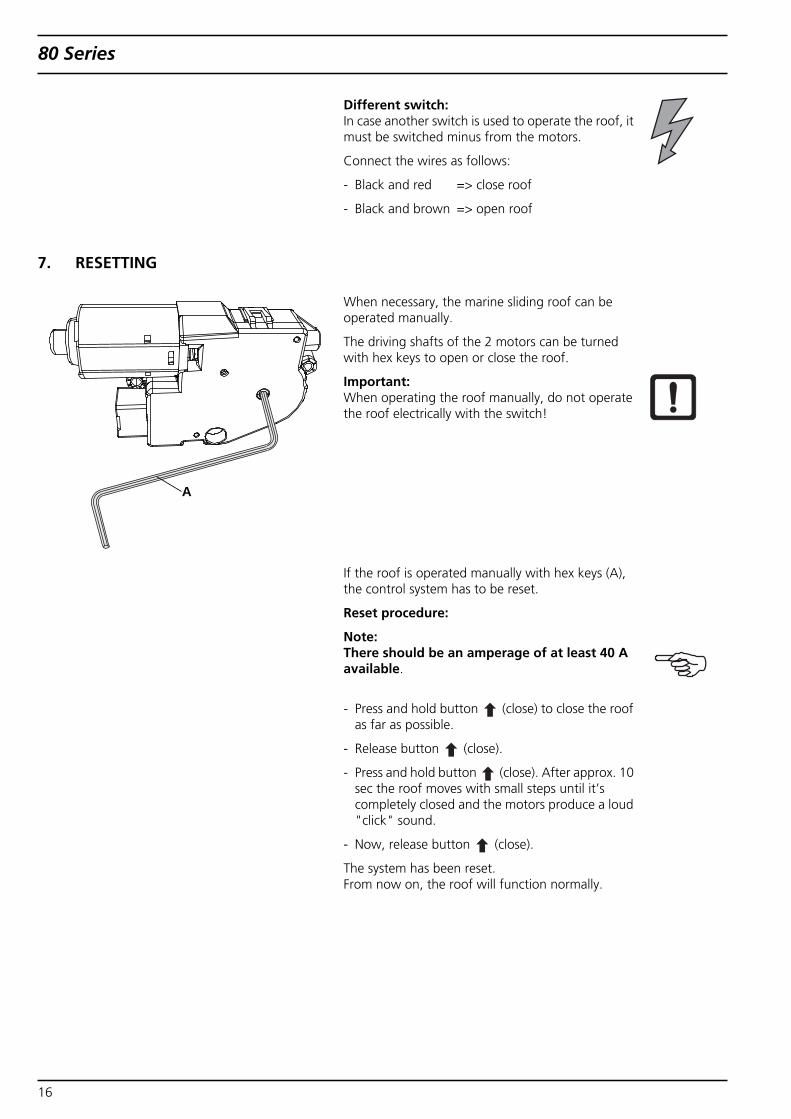
7. RESETTING
Different switch:In case another switch is used to operate the roof, itmust be switched minus from the motors.
Connect the wires as follows:
- Black and red => close roof
- Black and brown => open roof
When necessary, the marine sliding roof can beoperated manually.
The driving shafts of the 2 motors can be turnedwith hex keys to open or close the roof.
Important:When operating the roof manually, do not operatethe roof electrically with the switch!
If the roof is operated manually with hex keys (A),the control system has to be reset.
Reset procedure:
Note:There should be an amperage of at least 40 Aavailable.
- Press and hold button (close) to close the roofas far as possible.
- Release button (close).
- Press and hold button (close). After approx. 10sec the roof moves with small steps until it’scompletely closed and the motors produce a loud"click" sound.
- Now, release button (close).
The system has been reset.From now on, the roof will function normally.
A
16
80 Series
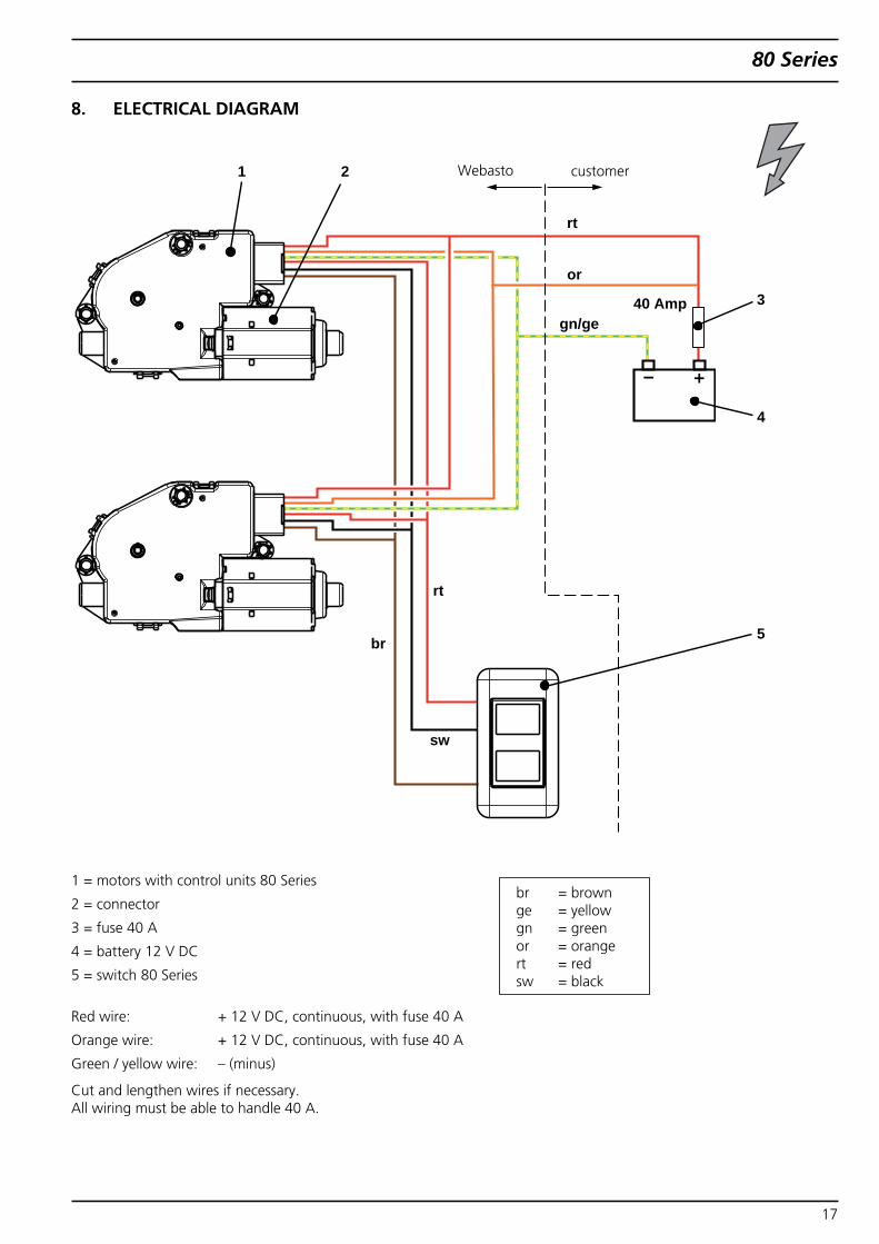
8. ELECTRICAL DIAGRAM
1 = motors with control units 80 Series
2 = connector
3 = fuse 40 A
4 = battery 12 V DC
5 = switch 80 Series
Red wire: + 12 V DC, continuous, with fuse 40 A
Orange wire: + 12 V DC, continuous, with fuse 40 A
Green / yellow wire: – (minus)
Cut and lengthen wires if necessary.All wiring must be able to handle 40 A.
Webasto
rt
or
rt
br
sw
gn/ge
1 2
3
4
5
40 Amp
customer
br = brownge = yellowgn = greenor = orangert = redsw = black
17
80 Series
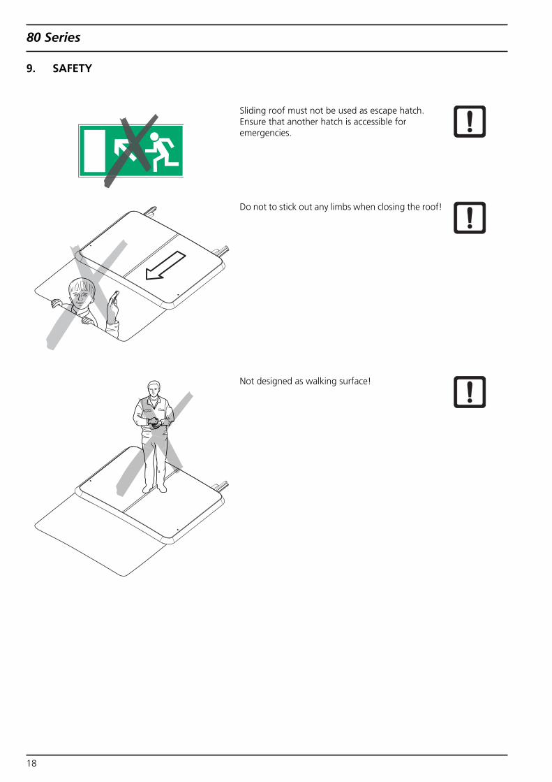
9. SAFETY
Sliding roof must not be used as escape hatch.Ensure that another hatch is accessible foremergencies.
Do not to stick out any limbs when closing the roof!
Not designed as walking surface!
18
80 Series
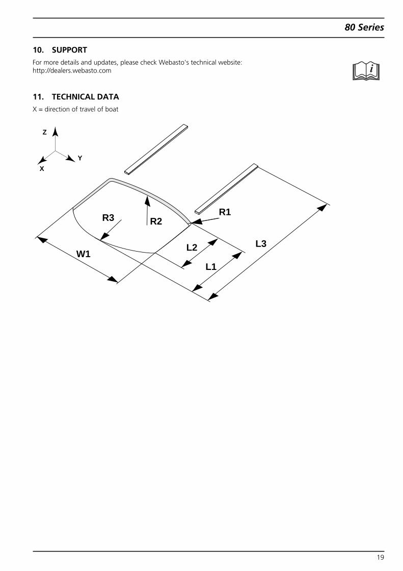
10. SUPPORTFor more details and updates, please check Webasto's technical website:http://dealers.webasto.com
11. TECHNICAL DATAX = direction of travel of boat
L3
R2
W1
R1
Z
XY
R3
L2
L1
19
80 Series
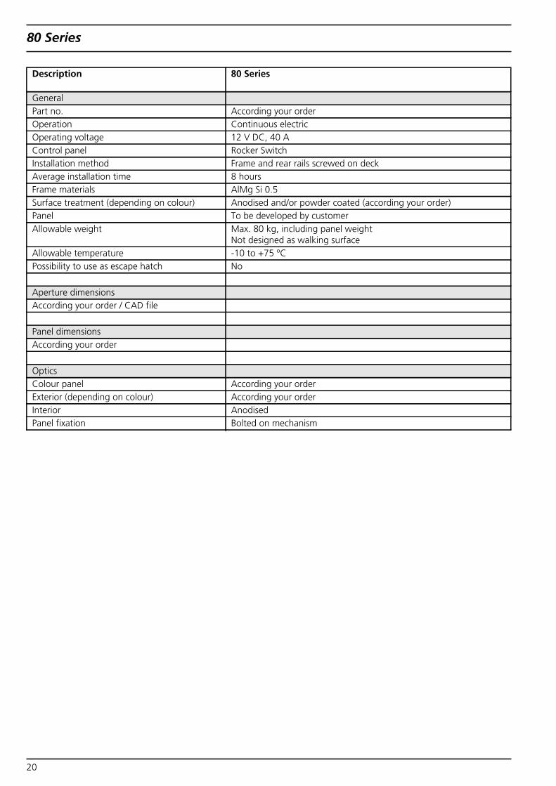
Description 80 Series
GeneralPart no. According your orderOperation Continuous electricOperating voltage 12 V DC, 40 AControl panel Rocker SwitchInstallation method Frame and rear rails screwed on deckAverage installation time 8 hoursFrame materials AlMg Si 0.5Surface treatment (depending on colour) Anodised and/or powder coated (according your order)Panel To be developed by customerAllowable weight Max. 80 kg, including panel weight
Not designed as walking surfaceAllowable temperature -10 to +75 ºCPossibility to use as escape hatch No
Aperture dimensionsAccording your order / CAD file
Panel dimensionsAccording your order
OpticsColour panel According your orderExterior (depending on colour) According your orderInterior AnodisedPanel fixation Bolted on mechanism
20
80 Series
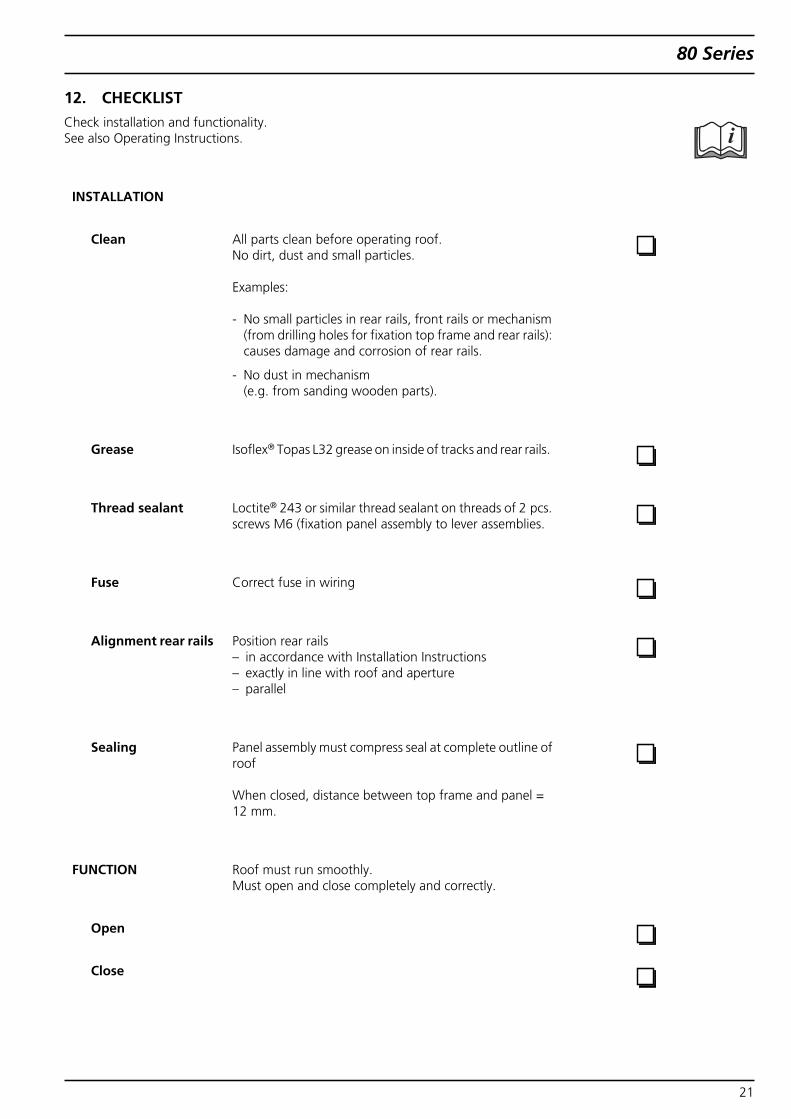
12. CHECKLISTCheck installation and functionality.See also Operating Instructions.
INSTALLATION
Clean All parts clean before operating roof.No dirt, dust and small particles.
Examples:
- No small particles in rear rails, front rails or mechanism(from drilling holes for fixation top frame and rear rails):causes damage and corrosion of rear rails.
- No dust in mechanism(e.g. from sanding wooden parts).
Grease Isoflex® Topas L32 grease on inside of tracks and rear rails.
Thread sealant Loctite® 243 or similar thread sealant on threads of 2 pcs.screws M6 (fixation panel assembly to lever assemblies.
Fuse Correct fuse in wiring
Alignment rear rails Position rear rails– in accordance with Installation Instructions– exactly in line with roof and aperture– parallel
Sealing Panel assembly must compress seal at complete outline ofroof
When closed, distance between top frame and panel =12 mm.
FUNCTION Roof must run smoothly.Must open and close completely and correctly.
Open
Close
21

80 Series
22

.339
2212
B•
08/1
1•
Erro
rsan
dom
issi
ons
exce
pted
•Pr
inte
din
The
Net
herla
nds
•©
Web
asto
AG
,GC
S20
11
Im Fall einer mehrsprachigen Version ist Englisch verbindlich.
In multilingual versions the English language is binding.
Dans le cas d'une version redigee en plusieurs langues, l'anglais est alors la langue qui fait foi.
Bij een meertalige versie is de Engelse versie bindend.
Webasto Product International NLConstructieweg 47NL - 8263 BC KampenThe NetherlandsPhone: +31 (0) 38 337 11 37Fax: +31 (0) 38 332 51 81
Iden
t-N
o
E-mail: [email protected]: www.webasto.com
http://dealers.webasto.com