MARINE ELECTRICIAN - RF Communication-Electronics … - Fundamentals of Electricity/08... · mci...
316
MCI 1141B MARINE CORPS INSTITUTE MARINE ELECTRICIAN MARINE BARRACKS WASHINGTON, DC
-
Upload
nguyenxuyen -
Category
Documents
-
view
222 -
download
5
Transcript of MARINE ELECTRICIAN - RF Communication-Electronics … - Fundamentals of Electricity/08... · mci...

MCI 1141B
MARINE CORPS INSTITUTE
MARINE ELECTRICIAN
MARINE BARRACKS WASHINGTON, DC


UNITED STATES MARINE CORPS MARINE CORPS INSTITUTE
912 CHARLES POOR STREET SE WASHINGTON NAVY YARD DC 20391-5680
IN REPLY REFER TO:
1550 Ser 2563 1 Jun 09 From: Director To: Marine Corps Institute Student Subj: MARINE ELECTRICIAN (MCI 1141B) 1. Purpose. The subject course provides instruction on the basic fundamentals of electricity, safety, power generation and distribution of electricity. 2. Scope. The subject course provides instruction on the deployment, installation, and safety of all forms of electrical power and distribution equipment, and those functions that are essential to all units that are establishing an operational base within a field environment. 3. Applicability. This course is intended for instructional purposes only. This course is designed for the Marine, private through staff sergeant, MOS 1141, Marine Electrician. This course can also be useful to units/commands that desire to enhance their understanding of electrical distribution equipment of their non-utilities MOS personnel. 4. Recommendations. Comments and recommendations on the contents of the course are invited and will aid in subsequent course revisions. Please complete the course evaluation questionnaire at the end of the final examination. Return the questionnaire and the examination booklet to your proctor. M.S. REICHENBAUGH By direction
“THIS DOCUMENT IS UNCLASSIFIED”

(This page intentionally left blank.)

MCI Course 1141B i
Table of Contents
Page Contents ............................................................................................................................ i Student Information .......................................................................................................... iii Study Guide ...................................................................................................................... v Study Unit 1 Fundamentals of Electricity .......................................................... 1-1
Lesson 1 Electricity...................................................................................... 1-3 Lesson 2 Electrical Theory........................................................................... 1-19 Lesson 3 Circuits.......................................................................................... 1-35 Lesson 4 Electrical Safety............................................................................ 1-49 Lesson 5 First Aid ........................................................................................ 1-65
Study Unit 2 Electrical Equipment..................................................................... 2-1
Lesson 1 Power Sources............................................................................... 2-3 Lesson 2 Electrical Wire .............................................................................. 2-21 Lesson 3 International Electricity ................................................................ 2-45
Study Unit 3 Generator Site ............................................................................... 3-1
Lesson 1 Tactical Generators ....................................................................... 3-3 Lesson 2 Grounding and Bonding................................................................ 3-21
Study Unit 4 Electrical Distribution Systems .................................................... 4-1
Lesson 1 Mobile Electric Power Distribution System ................................. 4-3 Lesson 2 Mobile Electric Power Distribution System-Replacement........... 4-19 Lesson 3 Bus Bar.......................................................................................... 4-41
Study Unit 5 Tools ............................................................................................. 5-1
Lesson 1 Lineman Toolkit............................................................................ 5-3 Lesson 2 Test Measuring Equipment ........................................................... 5-9
Appendix A....................................................................................................................... A-1 Appendix B ....................................................................................................................... B-1 Review Lesson .................................................................................................................. R-1

MCI Course 1141B ii
(This page intentionally left blank.)

MCI Course 1141B iii
Student Information
Number and Title
MCI 1141B MARINE ELECTRICIAN
Study Hours 9
Course Materials
Text
Review Agency Utilities Instruction Company
Marine Corps Engineer School, Camp Lejeune, NC
Reserve Retirement Credits (RRC)
3
ACE This course is scheduled for review by the American Council on Education
during 2009.
Assistance For administrative assistance, have your training officer or NCO log on to the
MCI home page at www.mci.usmc.mil. Marines CONUS may call toll free 1-800-MCI-USMC. Marines worldwide may call commercial (202) 685-7596 or DSN 325-7596.

MCI Course 1141B 1-iv Study Unit 1
(This page intentionally left blank.)

MCI Course 1141B v
Study Guide
Congratulations Congratulations on your enrollment in a distance education course from the
Distance Learning and Technologies Department (DLTD) of the Marine Corps Institute (MCI). Since 1920, the Marine Corps Institute has been helping tens of thousands of hard-charging Marines, like you, improve their technical job performance skills through distance learning. By enrolling in this course, you have shown a desire to improve the skills you have and master new skills to enhance your job performance. The distance learning course you have chosen, MCI 1141B, Marine Electrician, provides instruction to all Marines planning and performing duties related with all fundamental aspects of electricity. You will learn electrical theory and proper electrical safety procedures. You will also learn procedures for testing and analyzing electricity through test measuring equipment. You will understand and implement proper electrical generation and distribution equipment for the safety of all personnel in a field environment. Finally, you will learn how to identify electrical symbols and understand that there are different standards of electricity in the world.
Your Personal Characteristics
• YOU ARE PROPERLY MOTIVATED. You have made a positive decision to get training on your own. Self-motivation is perhaps the most important force in learning or achieving anything. Doing whatever is necessary to learn is motivation. You have it!
• YOU SEEK TO IMPROVE YOURSELF. You are enrolled to improve
those skills you already possess, and to learn new skills. When you improve yourself, you improve the Corps!
• YOU HAVE THE INITIATIVE TO ACT. By acting on your own, you
have shown you are a self-starter, willing to reach out for opportunities to learn and grow.
• YOU ACCEPT CHALLENGES. You have self-confidence and believe
in your ability to acquire knowledge and skills. You have the self-confidence to set goals and the ability to achieve them, enabling you to meet every challenge.
• YOU ARE ABLE TO SET AND ACCOMPLISH PRACTICAL
GOALS. You are willing to commit time, effort, and the resources necessary to set and accomplish your goals. These professional traits will help you successfully complete this distance learning course.
Continued on next page
MCI Course 1141B 1-vi Study Unit 1
Study Guide, Continued
Beginning Your Course
Before you actually begin this course of study, read the student information page. If you find any course materials missing, notify your training officer or training NCO. If you have all the required materials, you are ready to begin. To begin your course of study, familiarize yourself with the structure of the course text. One way to do this is to read the table of contents. Notice the table of contents covers specific areas of study and the order in which they are presented. You will find the text divided into several study units. Each study unit is comprised of two or more lessons and lesson exercises.
Leafing Through the Text
Leaf through the text and look at the course. Read a few lesson exercise questions to get an idea of the type of material in the course. If the course has additional study aids, such as a handbook or plotting board, familiarize yourself with them.
The First Study Unit
Turn to the first page of study unit 1. On this page, you will find an introduction to the study unit and generally the first study unit lesson. Study unit lessons contain learning objectives, lesson text, and exercises.
Reading the Learning Objectives
Learning objectives describe in concise terms what the successful learner, you, will be able to do as a result of mastering the content of the lesson text. Read the objectives for each lesson and then read the lesson text. As you read the lesson text, make notes on the points you feel are important.
Completing the Exercises
To determine your mastery of the learning objectives and text, complete the exercises developed for you. Exercises are located at the end of each lesson, and at the end of each study unit. Without referring to the text, complete the exercise questions and then check your responses against those provided.
Continued on next page

MCI Course 1141B 1-vii Study Unit 1
Study Guide, Continued, Continued
Continuing to March
Continue on to the next lesson, repeating the above process until you have completed all lessons in the study unit. Follow the same procedures for each study unit in the course.
Preparing for the Final Exam
To prepare for your final exam, you must review what you learned in the course. The following suggestions will help make the review interesting and challenging. • CHALLENGE YOURSELF. Try to recall the entire learning sequence
without referring to the text. Can you do it? Now look back at the text to see if you have left anything out. This review should be interesting. Undoubtedly, you’ll find you were not able to recall everything. But with a little effort, you’ll be able to recall a great deal of the information.
• USE UNUSED MINUTES. Use your spare moments to review. Read
your notes or a part of a study unit, rework exercise items, review again; you can do many of these things during the unused minutes of every day.
• APPLY WHAT YOU HAVE LEARNED. It is always best to use the
skill or knowledge you’ve learned as soon as possible. If it isn’t possible to actually use the skill or knowledge, at least try to imagine a situation in which you would apply this learning. For example make up and solve your own problems. Or, better still, make up and solve problems that use most of the elements of a study unit.
• USE THE “SHAKEDOWN CRUISE” TECHNIQUE. Ask another
Marine to lend a hand by asking you questions about the course. Choose a particular study unit and let your buddy “fire away.” This technique can be interesting and challenging for both of you!
• MAKE REVIEWS FUN AND BENEFICIAL. Reviews are good habits
that enhance learning. They don’t have to be long and tedious. In fact, some learners find short reviews conducted more often prove more beneficial.
Continued on next page

MCI Course 1141B 1-viii Study Unit 1
Study Guide, Continued, Continued
Tackling the Final Exam
When you have completed your study of the course material and are confident with the results attained on your study unit exercises, take the sealed envelope marked “FINAL EXAM” to your unit training NCO or training officer. Your training NCO or officer will administer the final examination and return the examination and the answer sheet to MCI for grading. Before taking your final examination, read the directions on the DP-37 answer sheet carefully.
Completing Your Course
The sooner you complete your course, the sooner you can better yourself by applying what you’ve learned! HOWEVER--you do have 2 years from the date of enrollment to complete this course.
Graduating! As a graduate of this distance education course and as a dedicated Marine,
your job performance skills will improve, benefiting you, your unit, and the Marine Corps.
Semper Fidelis!

MCI Course 1141B 1-1 Study Unit 1
STUDY UNIT 1
FUNDAMENTALS OF ELECTRICITY
Overview
Scope Electricity is a general term for the variety of phenomena resulting from the
presence and flow of electric charge that is used everyday. Together with magnetism, it constitutes the fundamental interaction known as electro-magnetism. Electricity includes many well-known physical phenomenal such as lightning, electric fields, and electric currents, and is used in industrial applications such as electronics and electrical power. In this study unit, we will cover electricity from its early roots to how it is used today. We will discuss how various theories were discovered and how those theories developed into applications. You will learn how to identify its key concepts and perform electrical calculations in determining those concepts. You will also learn the safety steps associated with electricity and how to render potential first aid if required.
In This Study Unit
This study unit contains the following lessons:
Lesson See Page
Electricity 1-3 Electrical Theory 1-19 Circuits 1-35 Electrical Safety 1-49 First Aid 1-65

MCI Course 1141B 1-2 Study Unit 1
(This page intentionally left blank.)

MCI Course 1141B 1-3 Study Unit 1, Lesson 1
LESSON 1
ELECTRICITY
Introduction
Scope Becoming a Marine electrician requires you to fully understand the history
and basic elements of what electricity is and how it works. In this lesson, we will define electricity and its history; identify parts of an atom, conductor, and insulator; and the key concepts and symbols used in the electrical field.
Learning Objectives
Upon completion of this lesson, you should be able to • Define electricity.
• Identify the atomic structure.
• Identify units of measure used in electricity.
In This Lesson This lesson contains the following topics:
Topic See Page Introduction 1-3 History 1-4 Atomic Structure 1-5 Concepts of Electricity 1-11 Symbols 1-14 Lesson 1 Exercise 1-15

MCI Course 1141B 1-4 Study Unit 1, Lesson 1
History
Early History Electricity is defined as “the force which moves electrons through a
conductor.” The first written records describing electrical behavior were made 2,500 years ago. The Greeks would rub cloth over amber, a translucent (semitransparent) yellowish mineral, which in its natural form is composed of fossilized resin. The Greeks found that by rubbing the cloth over the amber would create an attraction to feathers, cloth fibers, and other lightweight material. The Greek name for amber was “elektron.” From elektron came the word electric, which at first meant “being like amber,” or having the property of attraction.
Experiment Presently, little more is known than the ancient Greeks knew about the
fundamental nature of electricity. Scientific exploration into the phenomenon began during the European Renaissance due in part from Benjamin Franklin’s famous investigations into lightning and its curiosity to static electricity. This discovery sparked the interests of later scientists whose work provided the basis for modern technology. They include • Michael Faraday (1791-1867) • Luigi Galvani (1737-1798) • Alessandro Volta (1745-1827) • Andre-Marie Ampere (1775-1836) • George Simon Ohm (1789-1854)
Modern Advancement
Since the experimentation fields of 18th and early 19th centuries, scientists have continued to study and harness the lessons and theories that the early pioneers have created. The invention of electronics and other increased technology was spurred and created by the masters of the late 19th and early 20th century. Some of these men that became giants of electrical engineering are • Nikola Tesla • Samuel Morse • Antonio Meucci • Thomas Edison • George Westinghouse • Alexander Graham Bell

MCI Course 1141B 1-5 Study Unit 1, Lesson 1
Atomic Structure
Elements Elements, or a chemical element, were first used by the Greek philosopher
Plato in about 360 B.C. Since then, many other chemists and scientists discovered and classified the many different types of elements. Common examples of elements are hydrogen, nitrogen, and carbon. Currently, there are 117 known elements (in this context “known” means observed well enough), and of 117 known elements 94 of them occur naturally on Earth. The remaining elements not found on Earth have been derived artificially. The elements are listed by name, symbol, atomic number, and density, which the most convenient presentation of the elements is in a periodic table, also grouping the elements with similar chemical properties. Note: Since there are many different types of elements, there are many
different types of atoms.
Atoms In the study of chemistry, the element is far from being the smallest particle
in which matter may be subdivided. The atom is the smallest particle that makes up that type of material called an element. This idea that all matter is composed of atoms dates back more than 2,000 years ago to the Greeks. Many centuries have passed and physicists have explored the interior of the atom and discovered many subdivisions within it. An atom is composed of subatomic particles called • Protons • Neutrons • Electrons
Protons Protons have a positive charge and are relatively heavy in weight compared to
an electron. The most important properties of the proton are its positive charge and its weight. The number of protons, which is usually the same as the number of electrons, determines the identity of the element. All protons are alike and they are located in what is called the nucleus, or center, of the atom. The nucleus is the dense massive center of the atom.
Continued on next page
Larry E. Gugle
94 of them occur naturally on Earth.
Larry E. Gugle
Currently, there are
Larry E. Gugle
known elements
Larry E. Gugle
117
Larry E. Gugle
The remaining elements not found on Earth have been derived artificially.
Larry E. Gugle
The atom is the smallest particle that makes up that type of material called an element.
Larry E. Gugle
An atom is composed of subatomic particles called • Protons • Neutrons • Electrons
Larry E. Gugle
The elements are listed by name, symbol, atomic number, and density,
Larry E. Gugle
a periodic table,
Larry E. Gugle
in
Larry E. Gugle
Protons have a positive charge
MCI Course 1141B 1-6 Study Unit 1, Lesson 1
Atomic Structure, Continued
Neutrons A neutron has no charge, which means that they are electrically neutral.
Neutrality and weight are its most important properties, which mean that neutrons are the same weight as the protons and neutrons are alike, just like protons. They also form what is called the nucleus of the atom.
Electrons The most important aspect of the atom, in regards to electricity, is the
electron. The electron that has a negative charge is the lightest, in regards to weight, compared to the protons and neutrons. Electrons are located in shells rotating around the nucleus of the atom.
Types To identify an atom, look at its protons and electrons. The number of
protons, which is usually the same as the number of electrons, determines the type of element. For example, a hydrogen atom would have one proton in its nucleus, and is surrounded by one electron. In the Periodic Table of Elements (shown on the previous page), the elements are in an ascending atomic order based on the number of planetary electrons concise lead and atomic weight the number of protons and neutrons.
Atomic Theory The atomic theory is the cornerstone of the electrical theory. The
arrangement of electrons around the nucleus determines most of the physical and chemical properties and the behavior of the element. The electrons of the atom are often pictured in distinct layers or shells around the nucleus. The innermost shell of electrons can contain no more than two electrons. The next shell contains no more than 8 electrons, the third no more than 18 and the fourth no more than 32.
Continued on next page
Larry E. Gugle
The atomic theory is the cornerstone of the electrical theory.
Larry E. Gugle
A neutron has no charge,
Larry E. Gugle
The electron that has a negative charge
Larry E. Gugle
The electrons of the atom are often pictured in distinct layers or shells around the nucleus.
Larry E. Gugle
The innermost shell of electrons can contain no more than two electrons.

MCI Course 1141B 1-7 Study Unit 1, Lesson 1
Atomic Structure, Continued
Example Look at the model of a copper atom. The 29 electrons of the copper atom are
arranged in four layers or shells. Two in the shell nearest the nucleus, 8 in the next, and 18 in the third, for a total of 28 electrons. The single 29th electron circulates all alone in the fourth shell as shown below.
Valence Electrons
The outermost shell is known as the valence shell, and electrons occupying this orbit are known as valence electrons. Whenever energy is applied to a valence electron, it may dislodge itself from its parent atom and is then known as a free electron. In this position, where it is relatively far from the positive nucleus and is screened from its attracting positive charge by the other electrons, this single electron is not tightly held to the atom and is fairly free to travel. The elements could be classified into the following two categories when associating them with electricity: • Metals • Non-metals
Metals If we examine the electron arrangement in all kinds of atoms, most of them
have one, two, or three electrons in an outer shell shielded from the positive nucleus by one or more inner shells of electrons. These elements are called metals, which are fairly good conductors of electricity because they have many free electrons that can move from atom to atom.
Continued on next page
Larry E. Gugle
The outermost shell is known as the valence shell, and electrons occupying this orbit are known as valence electrons.
MCI Course 1141B 1-8 Study Unit 1, Lesson 1
Atomic Structure, Continued
Non-Metals Elements with five, six, or seven electrons in their outermost ring are
classified as non-metals. Some non-metallic elements are sulfur and iodine. They are not good conductors for the following reasons: • Their outside electrons are not as well shielded from the attracting force of
the nucleus. This occurs due to the relatively fewer electrons in the inside shells helping to screen any individual outer electron from the attracting force of the nucleus.
• A shell of eight electrons has a degree of energy stability. Atoms with
seven, six, or five electrons in the outer shell will readily pick up and hold the one, two, or three electrons that will build the shell up to eight.
Conductors
Substances that permit the free motion of a large number of electrons are called conductors. Copper is considered a good conductor because it has many free electrons. The greater the number of electrons that can be made to move in a material under the application of a given force the better the conductive qualities of that material. A good conductor is said to have a low opposition or low resistance to the electron flow. The best conductor is silver, copper, and aluminum in that order. However, copper is used more extensively because it is less expensive to manufacture than silver. Some of the best conductors are arranged in accordance with their respective abilities: • Silver • Copper • Gold • Aluminum • Zinc • Brass • Iron
Continued on next page
MCI Course 1141B 1-9 Study Unit 1, Lesson 1
Atomic Structure, Continued
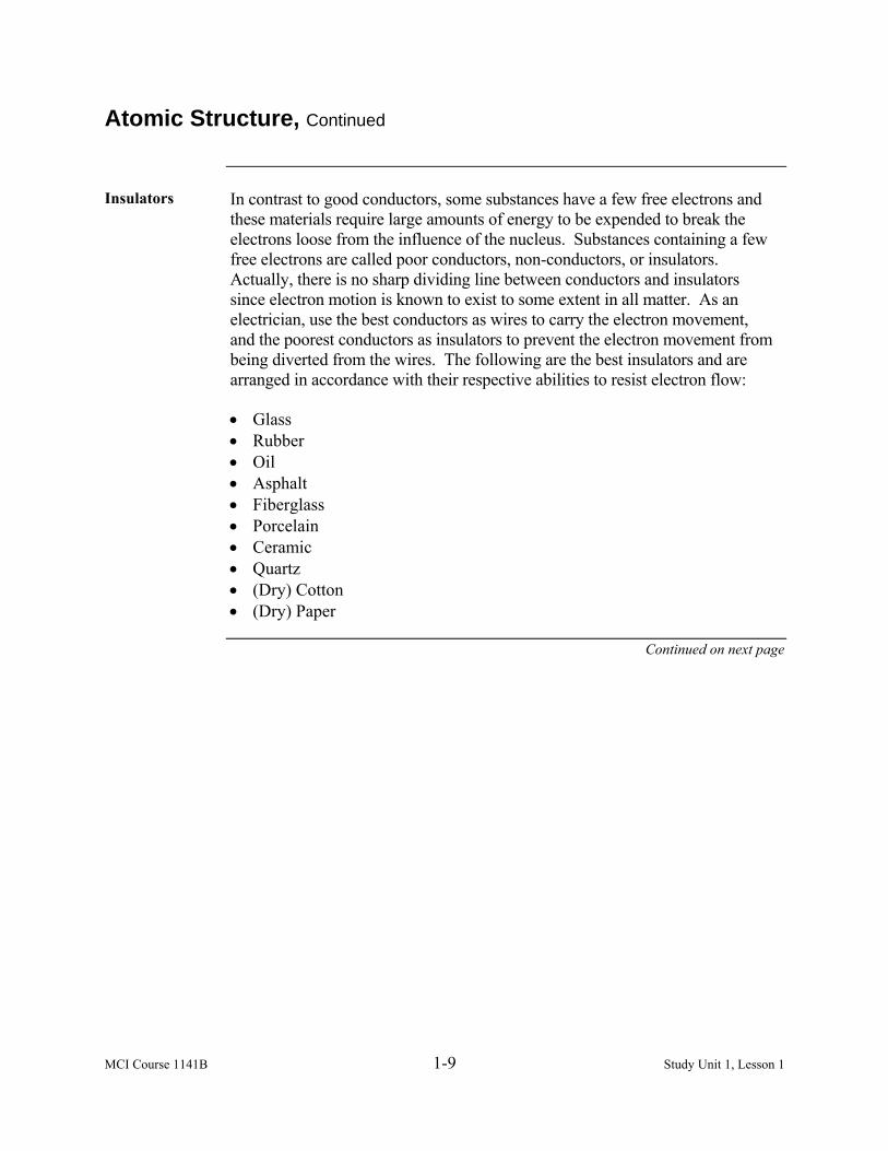
Insulators In contrast to good conductors, some substances have a few free electrons and
these materials require large amounts of energy to be expended to break the electrons loose from the influence of the nucleus. Substances containing a few free electrons are called poor conductors, non-conductors, or insulators. Actually, there is no sharp dividing line between conductors and insulators since electron motion is known to exist to some extent in all matter. As an electrician, use the best conductors as wires to carry the electron movement, and the poorest conductors as insulators to prevent the electron movement from being diverted from the wires. The following are the best insulators and are arranged in accordance with their respective abilities to resist electron flow: • Glass • Rubber • Oil • Asphalt • Fiberglass • Porcelain • Ceramic • Quartz • (Dry) Cotton • (Dry) Paper
Continued on next page

MCI Course 1141B 1-10 Study Unit 1, Lesson 1
Atomic Structure, Continued
Charged Bodies One of the fundamental laws of electricity is that like charges repel each other
and unlike charges attract each other. A positive charge and negative charge, being unlike, tend to move toward each other. In the atom, the negative electrons are drawn toward the positive protons in the nucleus. This attractive force is balanced by the electron’s centrifugal force caused by its rotation about the nucleus. As a result, the electrons remain in orbit and are not drawn into the nucleus. Electrons repel each other because of their like negative charges, and protons repel each other because of their like positive charges. An example is shown below:
Electric Field The space between and around charged bodies where their influence is felt is
called an electric field of force. The electric field is always terminated on material objects, which extends between positive and negative charges. Electrostatic line of force is a charged body represented by lines. These lines are imaginary and used merely to represent the direction and strength of the field. To avoid confusion, the lines of force exerted by a positive charge are always shown leaving the charge, and for a negative charge they are shown as entering.
Larry E. Gugle
One of the fundamental laws of electricity is that like charges repel each other and unlike charges attract each other.

MCI Course 1141B 1-11 Study Unit 1, Lesson 1
Concepts of Electricity
Introduction When dealing with any useful quantity, whether it is steel bars or electrons, a
system of measurement must be used to keep track of the production, transfer, and use of the commodity. The following are four fundamental concepts that constitute the elements of electrical energy: • Voltage • Current • Resistance • Watts
Voltage Voltage can best be described as the difference in potential or the difference
in the number of electrical charges. Electrons have a negative charge and flows to a positive charge. Voltage is always measured between two points of different potential. The unit of measure used for this is called the volt (V), which was named after the Italian physicist Alessandro Volta. The concept behind voltage is that it is the electrical pressure of electricity. This means the voltage is the force that pushes the electrons through a circuit the same way pressure pushes liquid through a pipe. The higher the voltage, the greater the force moving the electrons in an electrical circuit.
Methods Presently, there are six commonly used methods of producing voltage. The
table below shows some of the methods that are more widely used than others.
Method Description
Friction Voltage produced by rubbing two materials together Pressure Voltage produced by squeezing crystals of certain
substances Heat Voltage produced by heating the junction of two
unlike metals Light Voltage produced by light striking photosensitive
substances Chemical Action Voltage produced by chemical reaction in a battery Magnetism Voltage produced in a conductor when the conductor
moves through a magnetic field, or a magnetic field moves through the conductor in such a manner as to cut the magnetic lines of force of the field
Continued on next page
Larry E. Gugle
The following are four fundamental concepts that constitute the elements of electrical energy: • Voltage • Current • Resistance • Watts
Larry E. Gugle
Voltage can best be described as the difference in potential or the difference in the number of electrical charges.

MCI Course 1141B 1-12 Study Unit 1, Lesson 1
Concepts of Electricity, Continued
Current The drift or flow of electrons through a conductor is called electric current or
electron flow. The direction of electron movement is from a region of negative potential to a positive potential. Various terms may be used to describe current such as current flow, electron flow, or electron current. Realize that they all are relating to the term used here as current. To determine the amount of electrons flowing in an electrical circuit, it is necessary to adopt a unit of measurement of current flow. The term ampere (amp) is used to define the unit of measurement of the rate at which current flows. The symbol for current is I. Electrical current is classified into two general types: • Direct current • Alternating current
Direct Current Direct current (DC) (also referred to as constant polarity) is defined as the
flow of electrical charges in the same direction. This is typically located in a conductor such as a wire, but can also be located in semiconductors and insulators. A term formerly used for direct current was galvanic current.
Alternating Current
Alternating current (AC) is defined as the flow of electrical charges that may flow in either direction. Alternating current is an electrical current whose magnitude and direction vary cyclically, as opposed to direct current, whose direction remains constant. AC is the form in which electricity is delivered to businesses and residences and was made possible by Thomas Edison.
Continued on next page
Larry E. Gugle
current (DC)
Larry E. Gugle
Direct
Larry E. Gugle
is defined as the flow of electrical charges in the same direction.
Larry E. Gugle
Current
Larry E. Gugle
electron flow. The
Larry E. Gugle
drift or flow of electrons through a conductor is called electric current or
Larry E. Gugle
The
Larry E. Gugle
Alternating current (AC) is defined as the flow of electrical charges that may flow in either direction.
MCI Course 1141B 1-13 Study Unit 1, Lesson 1
Concepts of Electricity, Continued
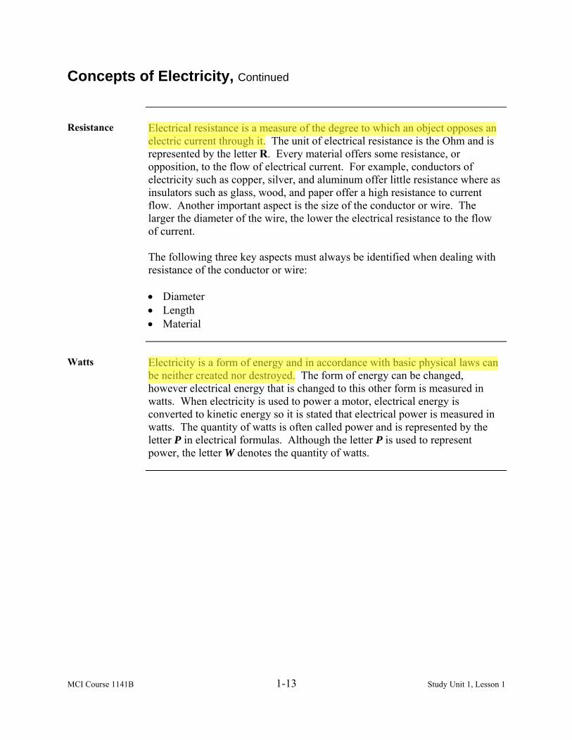
Resistance Electrical resistance is a measure of the degree to which an object opposes an
electric current through it. The unit of electrical resistance is the Ohm and is represented by the letter R. Every material offers some resistance, or opposition, to the flow of electrical current. For example, conductors of electricity such as copper, silver, and aluminum offer little resistance where as insulators such as glass, wood, and paper offer a high resistance to current flow. Another important aspect is the size of the conductor or wire. The larger the diameter of the wire, the lower the electrical resistance to the flow of current. The following three key aspects must always be identified when dealing with resistance of the conductor or wire: • Diameter • Length • Material
Watts Electricity is a form of energy and in accordance with basic physical laws can
be neither created nor destroyed. The form of energy can be changed, however electrical energy that is changed to this other form is measured in watts. When electricity is used to power a motor, electrical energy is converted to kinetic energy so it is stated that electrical power is measured in watts. The quantity of watts is often called power and is represented by the letter P in electrical formulas. Although the letter P is used to represent power, the letter W denotes the quantity of watts.
Larry E. Gugle
Electrical resistance is a measure of the degree to which an object opposes an electric current through it.
Larry E. Gugle
Electricity is a form of energy and in accordance with basic physical laws can be neither created nor destroyed.

MCI Course 1141B 1-14 Study Unit 1, Lesson 1
Symbols
Electrical Units Common components such as batteries, lights, and switches are all
represented on schematic symbols. Listed in the table below are symbols used to represent some common components.
Symbol Name of Quantity Derived Unit Unit
I Current Ampere A q Electric charge, quantity of
electricity Coulomb C
V Potential difference Volt V R, Z, X Resistance, impedance, reactance Ohm Ω ρ Power, electrical Watt W C Capacitance Farad F E Elastic Reciprocal
farad F-1
ε Permittivity Farad per metre F/m Electric susceptibility Dimensionless - G, Y, B Conductance, admittance,
susceptance Siemens S
G Conductivity Siemens per metre
S/m
H Intensity, magnetic field strength Ampere per metre
A/m
F Magnetic flux Weber Wb B Magnetic field, magnetic induction Tesla T R Reluctance Ampere-turns
per weber A/W b
L Inductance Henry H μr Permeability Henry per metre H/m Magnetic susceptibility Dimensionless -
MCI Course 1141B 1-15 Study Unit 1, Lesson 1 Exercise
Lesson 1 Exercise
Directions Complete exercise items 1 through 6 by performing the action required.
Check your answers against those listed at the end of this lesson.
Item 1 Which term best describes the following statement, “The force which moves
electrons through conductors”? a. Amber b. Electricity c. Lightning d. Voltage
Item 2 The elements that comprise an atom are
a. protons, neutrons, and electrons. b. protons, molecules, and neutrons. c. protons, electrons, and valence electrons. d. neutrons, molecules, and electrons.
Item 3 Which of the following substances permit the free motion of a large number
of electrons? a. Atoms b. Conductors c. Insulators d. Semiconductors
Item 4 Which of the following substances contain a few free electrons?
a. Atoms b. Conductors c. Insulators d. Semiconductors
Continued on next page

MCI Course 1141B 1-16 Study Unit 1, Lesson 1 Exercise
Lesson 1 Exercise, Continued
Item 5 A(n) ________________ is the internal friction that hinders or retards the
flow of electrons through any material. a. alternating current b. direct current c. resistance d. voltage
Item 6 When converting electrical energy to kinetic, what is the unit of measure?
a. Amp b. Atom c. Volt d. Watt
Continued on next page

MCI Course 1141B 1-17 Study Unit 1, Lesson 1 Exercise
Lesson 1 Exercise, Continued
Answers The table below lists the answers to the exercise items. If you have questions
about these items, refer to the reference page.
Item Number Answer Reference 1 b 1-4 2 a 1-5 3 b 1-8 4 c 1-9 5 c 1-13 6 d 1-13

MCI Course 1141B 1-18 Study Unit 1, Lesson 1 Exercise
(This page intentionally left blank.)

MCI Course 1141B 1-19 Study Unit 1, Lesson 2
LESSON 2
ELECTRICAL THEORY
Introduction
Scope Now that we understand what electricity is and where it originates, we will
discuss the law’s centerpiece to all electrical matters. In this lesson, we will identify Ohm’s Law, one of the most important formulas in electrical theory. Ohm’s Law enables us to compute unknown circuit quantities to use again in later problem-solving equations involving other theories and laws.
Learning Objectives
Upon completion of this lesson, you should be able to • Identify the equation that represents Ohm’s Law. • Define terms used in electrical theory. • Define the types of mechanical energy.
• Identify the equation that represents power.
• Employ Ohm’s Law formula. • Identify the common metric prefixes in electrical theory.
In This Lesson This lesson contains the following topics:
Topic See Page Introduction 1-19 Ohm’s Law 1-20 Energy 1-22 Power 1-24 PIRE Wheel 1-28 Metric Prefixes 1-29 Lesson 2 Exercise 1-31

MCI Course 1141B 1-20 Study Unit 1, Lesson 2
Ohm’s Law
Introduction Ohm’s Law is one of the equations used in the analysis of electrical circuits,
whether the analysis is done by engineers or computers. Even though, today, computers running electronic computer-aided design and analysis programs do the bulk of the work predicting and optimizing the performance of electrical circuits (circuits fabricated on silicon chips), most electrical engineers still use Ohm’s Law every day. Whether designing or troubleshooting an electrical circuit, electrical engineers must have a working knowledge of the practical aspects of Ohm’s Law.
History The law is named after Georg Ohm whom, in a treatise published in 1827,
described measurements of applied voltage and current passing through simple electrical circuits containing various lengths of wire. This presented a slightly more complex equation than the equation shown below to explain his experimental results. The equation could not exist until the ohm was defined in 1861.
Definition Ohm’s Law states that in an electrical circuit, the current (I) passing through a
conductor from one terminal point on the conductor to another terminal point on the conductor is directly proportional to the potential difference (voltage E) across the two terminal points, and inversely proportional to the resistance (R) of the conductor between the two points.
• Current goes up when voltage goes up. • Current goes down when voltage goes down.
• Current goes up when resistance goes down. • Current goes down when resistance goes up.
In mathematical terms, this is simply stated as
REI =
Continued on next page
with constant R
with constant E
Larry E. Gugle
current (I)
Larry E. Gugle
the
Larry E. Gugle
is directly proportional to the potential difference (voltage E)
Larry E. Gugle
and inversely proportional to the resistance (R)

MCI Course 1141B 1-21 Study Unit 1, Lesson 2
Ohm’s Law, Continued
Definition, continued
Ohm’s Law can be algebraically transposed and rewritten into other forms:
RIE ×= and IER =
Law Circle Memorizing Ohm’s Law will help you encounter it in your future studies of
electricity and electronics. A popular memory device for some has Ohm’s Law arranged in a circle as shown below. To use the circle, place a finger on the letter representing the unknown circuit quantity. The other two letters will be properly arranged to indicate either multiplication or division.
Example
Look at the example to see how this works. Assume that you have a simple circuit that has an applied voltage (E) of 120 volts and a resistance (R) of 20 ohms. To find the current flow (I), simply divide the voltage by the resistance. In this case that would be:
Current = 120 volts = 6 amps
20 ohms

MCI Course 1141B 1-22 Study Unit 1, Lesson 2
Energy
Definition The word energy has many definitions. In physics and other sciences, energy
(from the Greek, energos, “active or working”) is a scalar physical quantity used to describe change. Energy is often represented by the symbol E. Energy may come in many different forms to include • Mechanical • Thermal • Radiation • Electrical • Chemical • Nuclear These forms are all equivalent and in some cases overlapping. They may be converted into other forms of energy, transferred to other matter or stored. While energy may be converted from one form to another, it is never created or destroyed. In this lesson, mechanical is the most widely used and will be the only one discussed.
Mechanical The study of mechanics concerns the motion of physical bodies and the forces
that act upon them. In physics, mechanical energy describes the potential energy and the kinetic energy present in the components of a mechanical system. When a given sum of mechanical energy is transferred (such as lifting a box), it is said that this amount of mechanical work has been done. Both mechanical energy and mechanical work are measured in the same units as energy in general. To place this in mathematical format, it would look like the formula shown below:
Work = Force x Distance
Challenge 1 How many foot pounds are required to move a box weighing 20 pounds
vertically 5 feet?
Work = 20 pounds x 5 feet
Answer 1 100 foot-pounds
Continued on next page

MCI Course 1141B 1-23 Study Unit 1, Lesson 2
Energy, Continued
Potential Potential energy is defined as a work of certain force (say, gravitational or
Coulomb) during change of the relative positions of the objects within a physical system. Looking at the example on the previous page, the 20-pound weight is lifted 5 feet and has 100 foot-pounds of energy that it did not have when it was on the ground. This energy is called potential energy and when the weight is permitted to fall back to the earth, it delivers 100 foot-pounds of energy to the earth.
Kinetic The kinetic energy of an object is the extra energy it possesses due to its
motion. It is defined as the work needed to accelerate a body of a given mass from rest to its current velocity. Having gained this energy during its acceleration, the body maintains this kinetic energy unless its speed changes.
Challenge 2 How much work is done by a ball player whose hand moves 6 feet while it is
applying an average 8-pound force to a ¾ pound ball? Use the equation on the previous page.
Answer 2 8 lbs of force x 6 feet = 48 ft-lbs.
The energy exists as the motion of the ball which is called kinetic energy.
Terms The purpose of these mechanical examples is to illustrate the meaning of such
terms as work, energy, potential energy, and kinetic energy. These terms are often used in electrical energy discussions, but are easier to visualize in mechanical energy examples.
Unit of Energy The foot-pound is the energy unit commonly used in the British system of
measurements. The metric unit of energy is called a joule. Most common electrical units are based on the joule as the unit of energy. The joule (shown below) is the work done when a force of one Newton is exerted through a distance of 1 meter.
1 J = .738 ft-lbs 1 ft-lb = 1.35 J
MCI Course 1141B 1-24 Study Unit 1, Lesson 2
Power
Definition The word power (P), as commonly used, means a variety of things. In
technical language, power means how fast work is done or how fast energy is transferred. Two useful definitions of the term power are as follows: • Power is the rate of doing work. • Power is the rate of energy conversion. It is important to understand what is meant by the statement, power is a rate. We do not purchase or sell electrical power. We purchase or sell electrical energy. Power indicates how fast the energy is used or produced.
Horsepower When James Watt (Watt was originated for his contributions to the
development of the steam engine that was later adopted by the 2nd Congress of the British Association for the Advancement of Sciences in 1889.) started to sell steam engines, he needed to express the capacity of his engines in terms of the horses they were to replace. Watt found that an average horse, working at a steady rate, could do 550 foot-pounds of work per second. This rate is the definition of 1 horsepower (hp), for an example, 1 hp = 550 ft-lb/sec. Considering that 1 minute has 60 seconds, it follows that 1 hp = 33,000 ft-lb/min. Horsepower can also be expressed in units of electrical power called watts (W): 1 hp = 746 W
Example One watt of power is dissipated when one volt of electrical pressure forces
one ampere of current through the resistance of one ohm. This relationship can be expressed mathematically by the following equation: P = E x I. The power equation lends itself to another such memory circle, just like Ohm’s Law, often referred as the PIRE diagram shown on page 1-28.
Continued on next page

MCI Course 1141B 1-25 Study Unit 1, Lesson 2
Power, Continued
Metric System In the metric system, power is measured in joules per second. This unit of
measurement corresponds to foot-pounds per second in the British system. Because the unit joule per second is so often used, it is replaced with the single term watt. Example: One watt is a rate of one joule per second. Refer to the table below
for a breakdown of power units to watts.
Power Units Watts 1 horsepower 746 watts
1 British Thermal Unit per second 1,055 watts 1 calorie per second 4.19 watts
1 foot-pound per second 1.36 watts
Basic Equations Using the diagram, we have three basic equations in which to work from:
IPE =
IEP ×=
EPI =
Challenge 1 A radio is rated at 36 watts. How many volts of electromotive force are
needed to force 3 amperes through the radio?
Answer 1
IPE =
336
=E
vE 12=
Continued on next page

MCI Course 1141B 1-26 Study Unit 1, Lesson 2
Power, Continued
2nd Power Equation
The power equation, P = E x I, may be combined with Ohm’s Law to yield the hybrid equation RIP 2= . Assume that we need to calculate the electrical power of a circuit for which the voltage is unknown. From Ohm’s Law, we know that RIE ×= , substituting IEP ×= , gets IRIP ××= or simply RIP 2= .
RIP 2= is an important formula to remember. The synonymous word power and term RI 2 have found their way into the vocabulary of people in the electrical trades. We speak of RI 2 losses (power losses in the form of heat),
RI 2 heating, and RI 2 ratings. Mathematically, the quantities of this equation may be transposed to yield two other equations:
2IPR =
RPI =2
Challenge 2 You have a 60-watt light bulb with a .5-ampere current flowing through it,
what is the resistance of the lamp?
Answer 2
2IPR =
2)5(.60
=R
25.60
=R
Ω= 240R
Continued on next page

MCI Course 1141B 1-27 Study Unit 1, Lesson 2
Power, Continued
3rd Power Equation
It is possible to develop yet a third formula by combing the power equation with Ohm’s Law. Beginning with IEP ×= , the quantity I is unknown.
From Ohm’s Law, we substitute the equality REI = .
Instead of IEP ×= we now haveREEP ×= , which is more commonly
stated asR
EP2
= . Again, we are able to transpose the equation to yield two
more equations: P
ER2
= and PRE = .
Challenge 3 A space heater has a 30-ohm of resistance connected to a voltage source of
120 volts. What is the amount of power converted to heat?
Answer 3
R
EP2
=
30120120×
=P
4120 ×=P
wattsP 480=
MCI Course 1141B 1-28 Study Unit 1, Lesson 2
PIRE Wheel
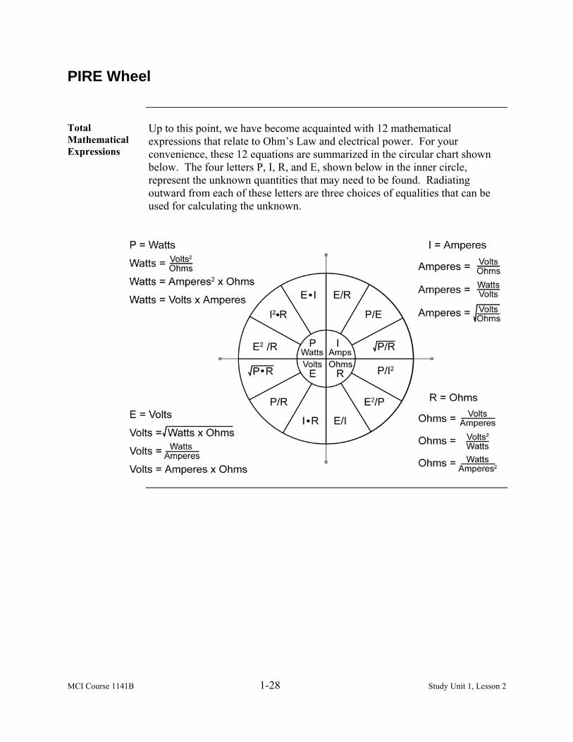
Total Mathematical Expressions
Up to this point, we have become acquainted with 12 mathematical expressions that relate to Ohm’s Law and electrical power. For your convenience, these 12 equations are summarized in the circular chart shown below. The four letters P, I, R, and E, shown below in the inner circle, represent the unknown quantities that may need to be found. Radiating outward from each of these letters are three choices of equalities that can be used for calculating the unknown.

MCI Course 1141B 1-29 Study Unit 1, Lesson 2
Metric Prefixes
Overview In electrical theory, we are often confronted with very large or small numbers.
To overcome the inherent inconvenience of dealing with such awkward numbers, it is customary to modify the basic measuring units by attaching a prefix to their multiples or submultiples. For instance, 1000 volts can be called 1 kilovolt. The example below shows that the word “kilo” stands for a multiple of 1,000 meaning 1 kilo is 1,000 times a unit.
Engineering Units
Note that metric prefixes, commonly called engineering units or engineering notation are in steps of 1,000 instead of 10. Engineering units are commonly used throughout the electrical field. Many scientific calculators have a function indicated as ENG that displays the answers in engineering units. Scientific notation units will be given in steps of 1,000 instead of 10 when this function is activated. The table below lists the more common metric prefixes that you will use in the electrical field.
Metric Prefix Numerical Equivalent
tera (T) 1,000,000,000,000 or 1210 giga (G) 1,000,000,000 or 910 mega (M) 1,000,000 or 610 kilo (K) 1,000 or 310
units 1 milli (m) .001 or 310− micro (µ) .000,001 or 610− nano (n) .000,000,001 or 910− pico (p) .000,000,000,001 or 1210− fimto (f) .000,000,000,000,001 or 1510−

MCI Course 1141B 1-30 Study Unit 1, Lesson 2
(This page intentionally left blank.)

MCI Course 1141B 1-31 Study Unit 1, Lesson 2 Exercise
Lesson 2 Exercise
Directions Complete exercise items 1 through 13 by performing the action required.
Check your answers against those listed at the end of this lesson.
Item 1 Which one of the following mathematical equations represents Ohm’s Law?
a. E = I x R b. I = E x R c. R = I x E d. R = E x I
Item 2 In physics, _________ is defined as a scalar physical quantity used to
describe change. a. power b. watt c. circuit d. energy
Item 3 What are the main types of mechanical energy?
a. Thermal and potential b. Chemical and kinetic c. Kinetic and potential d. Kinetic and thermal
Item 4 In mathematical terms, power is represented by which formula?
a. P = E x I b. P = E x R c. P = I x R d. P = V x R
Continued on next page

MCI Course 1141B 1-32 Study Unit 1, Lesson 2 Exercise
Lesson 2 Exercise, Continued
Item 5 Through Item 13
Matching: For items 5 through 13, match the metric prefix in column 1 with its numerical equivalent in column 2. Place your responses in the space provided.
Column 1 Metric Prefix
Column 2 Numerical Equivalent
___ 5. Tera (T) ___ 6. Giga (G) ___ 7. Mega (M) ___ 8. Kilo (K) ___ 9. Milli (m) ___10. Micro (µ) ___11. Nano (n) ___12. Pico (p) ___13. Fimto (f)
a. 1,000 b. .000,000,000,000,001 c. .001 d. 1,000,000,000 e. .000,000,000,001 f. 1,000,000,000,000 g. .000,001 h. 1,000,000 i. .000,000,001
Continued on next page

MCI Course 1141B 1-33 Study Unit 1, Lesson 2 Exercise
Lesson 2 Exercise, Continued
Answers The table below lists the answers to the exercise items. If you have questions
about these items, refer to the reference page.
Item Number Answer Reference 1 a 1-21 2 d 1-22 3 c 1-23 4 a 1-24 5 f 1-29 6 d 1-29 7 h 1-29 8 a 1-29 9 c 1-29 10 g 1-29 11 i 1-29 12 e 1-29 13 b 1-29

MCI Course 1141B 1-34 Study Unit 1, Lesson 2 Exercise
(This page intentionally left blank.)
MCI Course 1141B 1-35 Study Unit 1, Lesson 3
LESSON 3
CIRCUITS
Introduction
Scope We have just learned how to calculate electrical equations. We can now take
that information and develop an electrical circuit. In this lesson, we will cover the meaning and behavior of the electrical concepts in a series and parallel circuit to perform electrical calculations.
Learning Objectives
Upon completion of this lesson, you should be able to • Define a series circuit.
• Identify relationship of voltage, resistance, and current.
• Identify the voltage drop across a series circuit.
• Define a parallel circuit.
• Identify the total resistance in a parallel circuit using Ohm’s Law.
In This Lesson This lesson contains the following topics:
Topic See Page Introduction 1-35 Series Circuits 1-36 Parallel Circuits 1-39 Electrical Symbols 1-43 Lesson 3 Exercise 1-45

MCI Course 1141B 1-36 Study Unit 1, Lesson 3
Series Circuits
Definition A series circuit is any number of devices connected in a series so that there is
only a single circuit path for electron flow. Each device will have the same amount of current flowing through it. Charges will move in a series by moving from one device to another. If one of the devices in the circuit is broken, then no charge will move through the circuit because there is only one path. A series circuit is used for providing electricity to a security system. If there is a break in the line, the power will go out to all that is in the chain. The following illustration shows a series circuit:
Relationship of Voltage, Resistance, and Current
In a series circuit, the relationship between voltage, resistance, and current are different from other circuits. We have already discussed Ohm’s Law and understand how the relationships of these entities work. When describing a series circuit, the following three rules will apply when dealing with voltage, resistance, and current: • The total voltage is equal to the sum of all voltage drops through the
circuit. • The total resistance of a series circuit is equal to the sum of all individual
resistors. • The current in a series circuit is the same throughout the entire circuit.
Continued on next page

MCI Course 1141B 1-37 Study Unit 1, Lesson 3
Series Circuits, Continued
Voltage Voltage in a series circuit can be described in a variety of ways. If you had
eight lamps in a series circuit and applied 120 volts, assuming that all lamps in the circuit are equal size, then each lamp would have 15 volts running across its terminals. Mathematically stated
87654321 EEEEEEEEET +++++++=
Example 1 In a series circuit, six equal light bulbs are carrying 3 amps of current and
have a total voltage of 120 volts. What is the voltage of each bulb?
6120
=V
voltsV 20=
Resistance The total resistance of a series circuit is equal to the sum of all individual
resistors. Mathematically stated
654321 RRRRRRRT +++++=
Example 2 If we use example 1 of six light bulbs with 120 total applied volts and a
resistance reading of 2 ohms at the first light bulb, what would the total resistance be?
26 ×=TR Ω= 12TR
Current In a series circuit, the idea of adding individual values does not apply to
current. The current in a series circuit is the same throughout the circuit at each electrical device. Mathematically stated
654321 IIIIIIIT ======
Continued on next page

MCI Course 1141B 1-38 Study Unit 1, Lesson 3
Series Circuits, Continued
Example 3 Using the example, six light bulbs with 120 total applied volts with a current
reading at the sixth light bulb is 2 amps, what is the total amperage?
2 amps
Voltage Drop Have you ever wondered why the lights in a house dim when a motor starts?
The answer to that question is Ohm’s Law and the use of the series circuit principle. The sum of individual voltages equals the total applied voltage.
Example 4 Assume that each wire leading to the house has a .5-ohm resistance and the
lamps in the house cause a 2-ampere current in the line. We then have a series circuit and can calculate the voltage at the house. Each line wire is, in effect, a .5-ohm resistor with 2-amperes through it. Each electrical wire in the circuit is a 15-ohm resistor.
RIE ×= 5.2 ×=E
voltE 1= One volt is the potential energy used to maintain the 2-ampere current in the .5-ohm resistance of the wire. If there are 120 volts coming into the house, and two wires are used for the lights, the lights have a potential difference of 118 volts, 120 volts minus 2 volts (1 volt for each wire). If a motor is turned on so that the current in the line becomes 20 amperes instead of 2 amperes, more voltage will be required to maintain the current in the line leading to the house.
RIE ×= 5.20 ×=E
voltsE 10= for each wire Therefore, subtracting 20 volts from 120 volts gives us 100 volts delivered at the house. With 2 amperes in the line, the voltage at the house is 118 volts and with 20 amperes in the line, the voltage is 100 volts at the house. This means that lighting in the house is dimmer on 100 volts than on 118 volts since the decreased voltage means that there is less current in the lamps. The 2 or 20-volt loss is called the voltage drop on the line.

MCI Course 1141B 1-39 Study Unit 1, Lesson 3
Parallel Circuits
Definition A parallel circuit has more than one resistor or device and receives its name
from having multiple (parallel) paths for electrons to flow. Charges can move through any of several paths. If one of the items in the circuit is broken, no charge will move through that path, but other paths will continue to have charges flow through them. Parallel circuits are found in most household electrical wiring. This is done so that the lights do not stop working after you turn off the television. A parallel circuit is shown below:
Relationship of Voltage, Resistance, and Current
In a parallel circuit, the relationship between voltage, resistance, and current are going to become different from other circuits, like the series circuit we just discussed earlier. When describing a parallel circuit, the following three rules will apply when dealing with voltage, resistance, and current: • The total voltage across any branch in parallel is equal to the voltage
across any other branch and is also equal to the total voltage. • The total current is equal to the sum of the currents in all the branches of
the circuit. • The total resistance is applying Ohm’s Law to the total values of the
circuit.
Continued on next page

MCI Course 1141B 1-40 Study Unit 1, Lesson 3
Parallel Circuits, Continued
Voltage Voltage in a parallel circuit is the only voltage serving all load resistors in a
parallel circuit. If you have 120 volts entering a parallel circuit, 120 volts at the first device and 120 volts at the second device, then mathematically states
NT EEEEE =•••==== 321
Current In a parallel circuit, the total current will be equal to the sum of the currents in
all the branches of the circuit. Mathematically it will appear as
NT IIIII +•••+++= 321
Example 1 If you had six light bulbs with 120 volts and each light bulb was capable of 2
amps per light bulb, what is the total amount of amperage in the parallel circuit?
ampsII
T
T
1226
=×=
Resistance In a parallel circuit, the total resistance is always less than the resistance of
any branch. If the branches of a parallel circuit have the same resistance, then each will draw the same current. If the branches of a parallel circuit have different resistances, then each will draw a different current. Either in series or parallel circuits, when the resistance is larger, the current drawn is smaller. There are five computed methods for the total resistance of a parallel circuit. Three of those methods have special requirements to use a mathematical equation to solve them. We will focus on the two that require no special circumstances to solve total resistance in a parallel circuit: • Total resistance computed by Ohm’s Law • Total resistance computed by the reciprocal equation
Continued on next page

MCI Course 1141B 1-41 Study Unit 1, Lesson 3
Parallel Circuits, Continued
Ohm’s Law To compute the total resistance in a parallel circuit, apply Ohm’s Law to find
your answer. In some cases, you may have to find the total current first.
T
TT I
ER =
Example 2 Given a parallel circuit with three lights having 120 volts and 6 amps at each
individual light, what is the total resistance of this parallel circuit?
Ω=
=
×=
66.618
12036
120
T
T
T
R
R
R
Reciprocal Method
Another method used to determine resistance in a parallel circuit is to use the method known as the reciprocal method. This method is identified as reciprocal because of the mathematical equation it uses to solve problems for resistance, by reciprocating or inverting the values and adding them together. The formula is shown below:
NT RRRRR11111
321
+•••+++=
Continued on next page

MCI Course 1141B 1-42 Study Unit 1, Lesson 3
Parallel Circuits, Continued
Example 3 Given a parallel circuit with the resistance readings of three devices at 2
ohms, 4 ohms, and 8 ohms, what is the total resistance for the circuit?
Ω=
=
=
++=
++=
14.178871
81
82
841
81
41
211
T
T
T
T
T
R
R
R
R
R

MCI Course 1141B 1-43 Study Unit 1, Lesson 3
Electrical Symbols
Types The following types of electrical symbols are used.

MCI Course 1141B 1-44 Study Unit 1, Lesson 3
(This page intentionally left blank.)

MCI Course 1141B 1-45 Study Unit 1, Lesson 3 Exercise
Lesson 3 Exercise
Directions Complete items 1 through 7 by performing the action required. Check your
answers against those listed at the end of this lesson.
Item 1 When any number of devices is connected so that there is only a single circuit
path for electrons to flow, the circuit is described as a ____________ circuit. a. magnetic b. parallel c. series d. series-parallel
Item 2 In a series circuit, the total resistance is equal to the sum of the individual
a. amperage. b. atoms. c. resistors. d. voltage.
Item 3 In a series circuit, you have an amperage of 10 at the first receptacle and an
amperage of 10 at the second receptacle, how many total amps are there in this circuit? a. 10 b. 20 c. 40 d. 100
Item 4 A series circuit has 120 volts entering the circuit to provide power to six
lights. If the lights are all the same and they have the same resistance, what is the voltage drop at each light? a. 10 volts b. 20 volts c. 60 volts d. 120 volts
Continued on next page

MCI Course 1141B 1-46 Study Unit 1, Lesson 3 Exercise
Lesson 3 Exercise, Continued
Item 5 When any number of devices is connected so that there is more than one
circuit path for electrons to flow, the circuit is described as a _________ circuit. a. magnetic b. parallel c. series d. series-parallel
Item 6 What is the total resistance of a parallel circuit when there is a voltage of 120
and three lights each having a current of 5 amps, 10 amps, and 15 amps? a. 3 ohms b. 20 ohms c. 30 ohms d. 40 ohms
Item 7 What is the total resistance of a parallel circuit when the resistance of three
circuits is 10 ohms, 20 ohms, and 15 ohms? a. 30 ohms b. 4.01 ohms c. 4.61 ohms d. 5.35 ohms
Continued on next page

MCI Course 1141B 1-47 Study Unit 1, Lesson 3 Exercise
Lesson 3 Exercise, Continued
Answers The table below lists the answers to the exercise items. If you have questions
about these items, refer to the reference page.
Item Number Answer Reference Page 1 c 1-36 2 c 1-37 3 a 1-38 4 b 1-38 5 b 1-39 6 a 1-40 7 c 1-40

MCI Course 1141B 1-48 Study Unit 1, Lesson 3 Exercise
(This page intentionally left blank.)

MCI Course 1141B 1-49 Study Unit 1, Lesson 4
LESSON 4
ELECTRICAL SAFETY
Introduction
Scope Electricians are exposed to many potentially dangerous conditions and
situations. It is possible that the electrician could complete a full career without serious accident or injury, but should always be aware and remain constantly alert to any and all dangers. In this lesson, we will discover safe working practices when working with electricity. We will understand how to use operational risk management as a tool to ensure that safety is always paramount. We will also identify the process for lock-out and tag-out procedures.
Learning Objectives
Upon completion of this lesson, you should be able to • Identify safety principles.
• Identify operational risk management hazard control measures.
• Identify the categories associated with hazard severity.
• Identify the classes of fire extinguishers. • Identify the principles of lock-out/tag-out.
In This Lesson This lesson contains the following topics:
Topic See Page Introduction 1-49 Safety Guidelines 1-50 Operational Risk Management 1-52 Fire Extinguishers 1-58 Lock-Out/Tag-Out 1-59 Lesson 4 Exercise 1-61

MCI Course 1141B 1-50 Study Unit 1, Lesson 4
Safety Guidelines
Unsafe Work Practices
The following are unsafe work practices that are commonly violated by personnel when working with electricity: • Never work on a live circuit unless it is absolutely necessary. • Never work without having someone present who is qualified in CPR. • Never work with tools that are not properly insulated. • Never horseplay, wrestle, or scuffle with individuals around areas of
electricity. • Never work with jewelry and metal items that may come in contact with
electrical equipment or power lines such as unsecured zippers or metal fasteners.
• Never operate generator sets without proper hearing protection. • Never operate or activate electrical equipment or distribution systems,
which are not properly grounded, according to Article 250 in the National Electric Code.
• Never install an over current protection device unless it is equal to or less
than the amperage demand according to Article 240 of the National Electric Code.
Continued on next page

MCI Course 1141B 1-51 Study Unit 1, Lesson 4
Safety Guidelines, Continued
Warning Signs Warning signs prevent accidents and injury to electricians or other potential
personnel. They are necessary for notifying personnel or reminding them of a potential hazard. The National Electric Code states the following concerning warning signs: • Article 110.27 (C) states that entrances to rooms and other guarded
locations containing exposed live parts shall be marked with conspicuous warning signs forbidding unqualified personnel to enter.
• Article 450.8 states that the operating voltage of exposed live parts of
transformer installations shall be indicated by signs or visible marking on the equipment or structure.
It is important that any equipment that produces or distributes electricity must have a warning sign when identifying that area as being potentially dangerous. With the many different areas of operations engaged in the Marine Corps, it makes sense to display a second sign in the native language of the country to where you are located. We will discuss international electricity later in this course.
Precautions With the loss of life potential when working with electricity, the following
precautions should be followed to ensure the safety of everyone. • Use test equipment to ensure that electricity is secured before working on
any electrical equipment or material. • Use protective posture equipment to ensure safety, i.e. rubber gloves,
safety glasses, helmet or hard hat, and rubber boots. • Use insulating materials, such as rubber mats to protect yourself from
electrical shock, especially in damp areas.
OSHA Safety Needs
For additional information on the Occupational Health and Safety Agency (OSHA) safety needs, see Appendix B before the review lesson.

MCI Course 1141B 1-52 Study Unit 1, Lesson 4
Operational Risk Management
Background As a Marine electrician, you must integrate risk management into the
planning, preparation, and execution of your duties. Failing to conduct safe practices result in injuries or even fatalities.
Concept Operational Risk Management (ORM) is a decision making tool used by
personnel at all levels to increase operational effectiveness by identifying, assessing, and managing risks. Reducing the potential for loss increases the probability of a successful mission. The ability to make informed decisions also increases by providing a formal risk management process, which in turn minimizes risk to an acceptable level commensurate with mission accomplishment. Correct application of the ORM process will reduce mishaps and associated costs. Note: For a more detailed understanding of the ORM process, you are
encouraged to take the ORM Job Aid from the Marine Corps Institute library.
Process ORM uses the following five-step process to identify and control hazards:
Step Action 1 Identify hazards. 2 Assess hazards to determine risk. 3 Develop controls and make risk decisions. 4 Implement risk control. 5 Supervise and evaluate.
Identify Hazards
A hazard is any issue, real or potential, that can cause personal injury, death, property damage, mission degradation, or damage to the environment. Conduct a preliminary hazard analysis by listing all of the hazards associated with each step in the operational analysis along with the possible causes for hazards.
Assess Hazards For each hazard identified, determine the associated degree of risk in terms of
probability and severity. Although not required, the use of a matrix may be helpful in assessing hazards.
Continued on next page

MCI Course 1141B 1-53 Study Unit 1, Lesson 4
Operational Risk Management, Continued
Risk Control/ Risk Decision
Develop risk control options by starting with the most serious risk and select controls that will reduce the risk to a minimum consistent with mission accomplishment. With selected controls in place, decide if the residual risk is acceptable and the benefit of the operation outweighs the risk.
Implement Risk Controls
The following measures can be used to eliminate hazards or reduce the degree of risk:
Engineering
Controls Administrative Controls
Controls that use engineering methods to reduce risks by design, material selection, or substitution
Controls that can reduce risks through the following specific administrative actions: • Provide suitable warnings, markings, placards,
signs, and notices. • Establish written policies, programs, instructions,
and standard operating procedures. • Train personnel to recognize hazards and take
appropriate precautionary measures. • Limit the exposure to a hazard (by either reducing
the number of assets or personnel exposed, or the duration of exposure).
Note: Residual risk is derived as the risk that remains after controls have
been identified and selected.
Supervise/ Evaluate
Conduct follow-up evaluations of the controls to ensure they remain in place and have the desired effect. Supervise changes, which may require further ORM. Always take corrective action when necessary.
Continued on next page

MCI Course 1141B 1-54 Study Unit 1, Lesson 4
Operational Risk Management, Continued
ORM Process Levels
The ORM process exists on three levels: • Time Critical • Deliberate • In-depth Decide which of three levels to use based on the situation, proficiency level of personnel, and the amount of time and assets available. While it is preferable to perform a deliberate or in-depth ORM process for all evolutions, the time and resources will not always be available. One of the objectives of ORM training is to develop sufficient proficiency in applying the process so ORM becomes an automatic or intuitive part of the decision making methodology.
Time Critical An “on the run” mental or oral review of the situation using the five-step
process without recording the information on paper is often all that time will allow. The time critical level of ORM is employed by experienced personnel to consider risk while making decisions in time-compressed situations. This level is used during the execution phase of training or operations, as well as in the planning during crisis response scenarios.
Deliberate Application of the complete five-step process will aid in planning an
operation or evaluating procedures. This process is used to identify hazards and develop controls and is most effective when done in a group. Some examples of deliberate applications include • Planning of upcoming operations • Reviewing standard operating procedures • Reviewing training procedures • Damage control • Disaster response planning
Continued on next page

MCI Course 1141B 1-55 Study Unit 1, Lesson 4
Operational Risk Management, Continued
In-Depth In-depth involves a thorough risk assessment, especially the first two steps of
the five-step process. Research of available data, use of diagram and analysis tools, formal testing, or long-term tracking of the hazards associated with the operation are used to identify and access the hazards. The in-depth level of ORM is used to more thoroughly study the hazards and associated risk in a complex operation or system, or one in which the hazards are not well understood. Some examples of in-depth applications include • Long-term planning of complex operations • Introduction of new equipment, materials, and missions • Development of tactics and training curriculum • Major system overhaul or repair
Principles of ORM
ORM incorporates the following four principles: • Accept risk when benefits outweigh the cost. • Accept no unnecessary risk. • Anticipate and manage risk by planning. • Make risk decisions at the right level.
Risk Assessment Matrix
A matrix can be used to accomplish the ORM process. Using a matrix to quantify and prioritize the risks does not lessen the inherently subjective nature of risk assessment. However, a matrix does provide a consistent framework for evaluating risk. Although different matrixes may be used for various applications, the risk assessment tool should include the elements of hazard severity and mishap probability as shown below:
Category A B C D
I 1 1 2 3 II 1 2 3 4 III 2 3 4 5 IV 3 4 5 5
Continued on next page
MCI Course 1141B 1-56 Study Unit 1, Lesson 4
Operational Risk Management, Continued
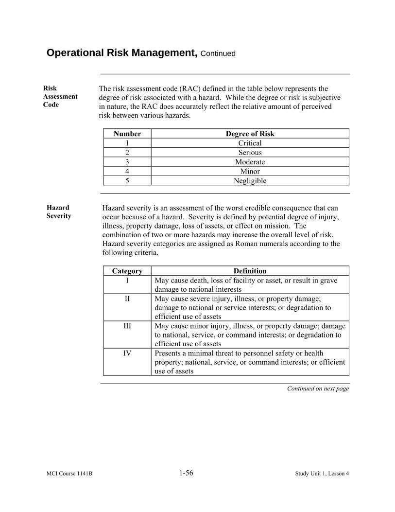
Risk Assessment Code
The risk assessment code (RAC) defined in the table below represents the degree of risk associated with a hazard. While the degree or risk is subjective in nature, the RAC does accurately reflect the relative amount of perceived risk between various hazards.
Number Degree of Risk
1 Critical 2 Serious 3 Moderate 4 Minor 5 Negligible
Hazard Severity
Hazard severity is an assessment of the worst credible consequence that can occur because of a hazard. Severity is defined by potential degree of injury, illness, property damage, loss of assets, or effect on mission. The combination of two or more hazards may increase the overall level of risk. Hazard severity categories are assigned as Roman numerals according to the following criteria.
Category Definition
I May cause death, loss of facility or asset, or result in grave damage to national interests
II May cause severe injury, illness, or property damage; damage to national or service interests; or degradation to efficient use of assets
III May cause minor injury, illness, or property damage; damage to national, service, or command interests; or degradation to efficient use of assets
IV Presents a minimal threat to personnel safety or health property; national, service, or command interests; or efficient use of assets
Continued on next page
MCI Course 1141B 1-57 Study Unit 1, Lesson 4
Operational Risk Management, Continued
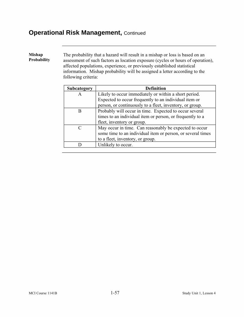
Mishap Probability
The probability that a hazard will result in a mishap or loss is based on an assessment of such factors as location exposure (cycles or hours of operation), affected populations, experience, or previously established statistical information. Mishap probability will be assigned a letter according to the following criteria:
Subcategory Definition
A Likely to occur immediately or within a short period. Expected to occur frequently to an individual item or person, or continuously to a fleet, inventory, or group.
B Probably will occur in time. Expected to occur several times to an individual item or person, or frequently to a fleet, inventory or group.
C May occur in time. Can reasonably be expected to occur some time to an individual item or person, or several times to a fleet, inventory, or group.
D Unlikely to occur.
MCI Course 1141B 1-58 Study Unit 1, Lesson 4
Fire Extinguishers
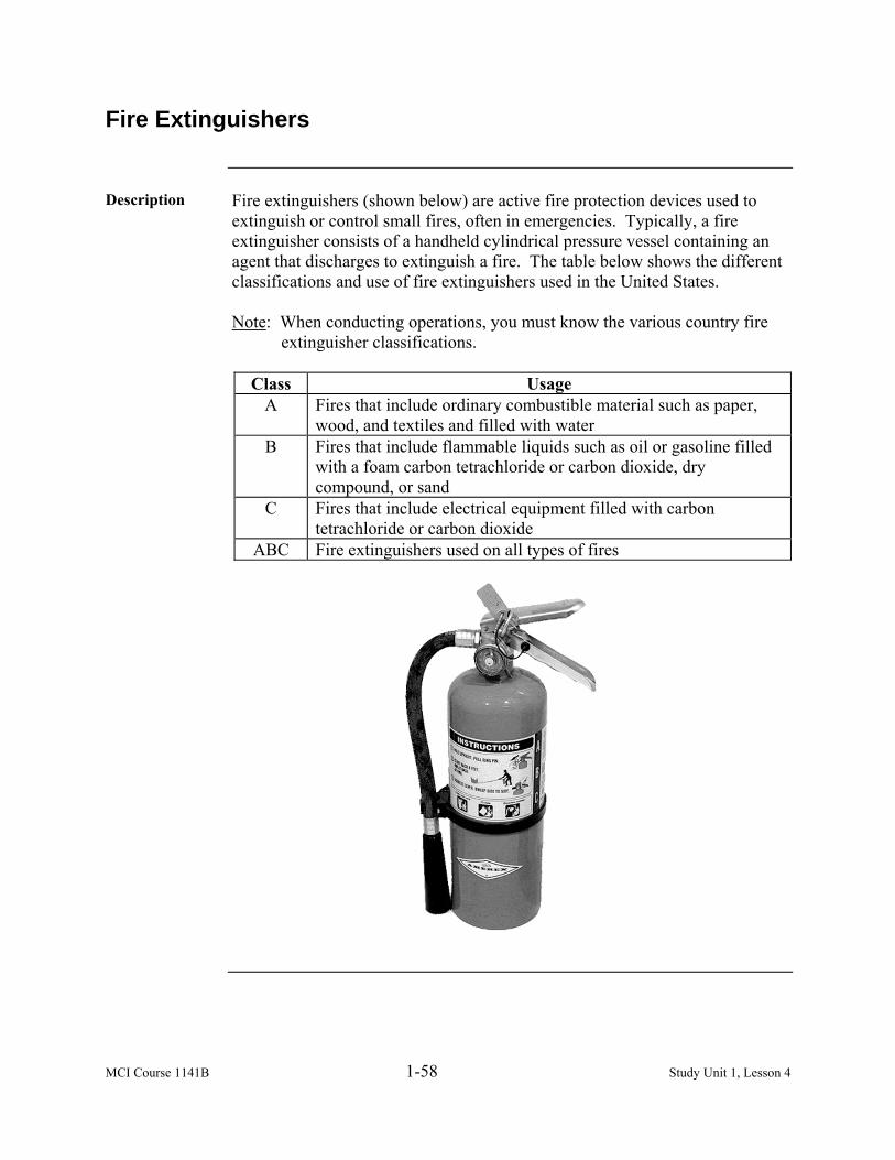
Description Fire extinguishers (shown below) are active fire protection devices used to
extinguish or control small fires, often in emergencies. Typically, a fire extinguisher consists of a handheld cylindrical pressure vessel containing an agent that discharges to extinguish a fire. The table below shows the different classifications and use of fire extinguishers used in the United States. Note: When conducting operations, you must know the various country fire
extinguisher classifications.
Class Usage A Fires that include ordinary combustible material such as paper,
wood, and textiles and filled with water B Fires that include flammable liquids such as oil or gasoline filled
with a foam carbon tetrachloride or carbon dioxide, dry compound, or sand
C Fires that include electrical equipment filled with carbon tetrachloride or carbon dioxide
ABC Fire extinguishers used on all types of fires

MCI Course 1141B 1-59 Study Unit 1, Lesson 4
Lock-Out/Tag-Out
Description Lock-out and tag-out is a safety program used mainly in the industry when
working with electricity. It requires that dangerous machines are properly shut off and not started again prior to the completion of maintenance or servicing. Lock-out and tag-out also requires that all hazardous energy sources (electricity) be isolated and rendered inoperative. For additional information, the Occupational Health and Safety Agency (OSHA) publication has the following two references: • OSHA 29 CFR 1910.147: Control of Hazardous Energy; Lock-out/Tag-out • OSHA 29 CFR 1926.417: Lock-out and Tagging of Circuits
Lock-Out Devices
The placement of a lock-out device, usually a lock, on an energy isolating device ensures the energy isolating device and the equipment being controlled may not be operated until the lock-out device is removed. Electrical panels and breakers are ideal locations to use lockout devices. In the United States, a red padlock is a standard safety device designating locking and securing hazardous energy. For an electrician, locks must be individually keyed and remain with the individual who placed the lock on the equipment to be serviced. (A lock-out device kit is shown below).
Continued on next page

MCI Course 1141B 1-60 Study Unit 1, Lesson 4
Lock-Out/Tag-Out, Continued
Tag-Out Devices
The placement of a tag-out device on an energy isolating device indicates that the energy isolating device and the equipment being controlled may not be operated until the tag-out device is removed. A tag or tag-out device must meet the following criteria: • Non-reusable • Attach by hand • Self-locking • Non-releasable with a minimum unlocking strength of no less than 50 lbs. • Basic characteristics of being at least equivalent to a one-piece, all
environment-tolerant cable tie.
Tag-Out Procedures
Tag-out should be employed by using the following guidelines: • Each tag must contain the name, picture, and department/organization of
the individual using the tag-out. • Individual must record the time and date of the disconnection. • Individual must record the type of work, maintenance, or servicing being
performed. • Individual must record the estimated duration of the tag-out. • Individual tag holder must apply his or her tag-out.
MCI Course 1141B 1-61 Study Unit 1, Lesson 4 Exercise
Lesson 4 Exercise
Directions Complete items 1 through 8 by performing the action required. Check your
answers against those listed at the end of this lesson.
Item 1 In electrical safety, never work on a ____________ circuit unless it is
absolutely necessary. a. live b. open c. faulty d. dead
Item 2 The process of identifying, assessing, and controlling risks arising from
operational factors and making decisions that balance costs with mission success is called a. hazard severity. b. mishap probability. c. operational risk management. d. operational management.
Item 3 The ORM five-step process is used to identify hazards, assess hazards to
determine risk, develop controls and make risk decisions, ____________, and supervise and evaluate. a. manage risk b. implement risk control c. develop tactics d. operate management
Item 4 The ORM process exists on three levels that are based on the ____________,
proficiency level of personnel, and amount of time and assets. a. cost b. money c. planning d. situation
Continued on next page

MCI Course 1141B 1-62 Study Unit 1, Lesson 4 Exercise
Lesson 4 Exercise, Continued
Item 5 The ____________ represents the degree of risk associated with a hazard and
reflect the relative amount of perceived risk between various hazards. a. ORM b. risk assessment matrix c. hazard severity code d. risk assessment code
Item 6 Which category results in the hazard causing death, loss of facility/asset or
result in grave damage to national interests? a. Category I b. Category II c. Category III d. Category IV
Item 7 What class of fire extinguisher is filled with water and fights fire that are
made from combustible material like wood, paper, and textiles? a. Class A b. Class B c. Class C d. Class ABC Fire
Item 8 Lock-out and tag-out requires that
a. you notify a supervisor before each phase of electrical maintenance. b. OSHA 29 CFR 1910.147 is present while conducting electrical
maintenance. c. Class ABC fire extinguishers are present while performing electrical
maintenance. d. dangerous machines are properly shut off and not started again, prior to
the completion of maintenance.
Continued on next page

MCI Course 1141B 1-63 Study Unit 1, Lesson 4 Exercise
Lesson 4 Exercise, Continued
Answers The table below lists the answers to the exercise items. If you have questions
about these items, refer to the reference page.
Item Number Answer Reference 1 a 1-50 2 c 1-52 3 b 1-52 4 d 1-54 5 d 1-56 6 a 1-56 7 a 1-58 8 d 1-59

MCI Course 1141B 1-64 Study Unit 1, Lesson 4 Exercise
(This page intentionally left blank.)

MCI Course 1141B 1-65 Study Unit 1, Lesson 5
LESSON 5
FIRST AID
Introduction
Scope An electrician can be exposed to many serious and sometime fatal hazards,
therefore, it is important to not only identify those hazards and reduce the risk, but also provide medical treatment if an accident occurs. Treatment generally consists of a series of simple, sometimes life-saving medical techniques that an individual, either with or without formal medical training, is trained to perform with minimal equipment or material. Knowing the basic techniques of first aid, you will help save a life from serious injury. In this lesson, we will discuss the steps required for aiding and treating an electrical shock casualty and conducting a pole top rescue.
Learning Objectives
Upon completion of this lesson, you should be able to • Define the effects of electrical shock.
• Identify the proper response to an electrical shock casualty.
• List the steps on providing first aid to an electrical shock casualty. • Identify steps in conducting a pole top rescue.
In This Lesson This lesson contains the following topics:
Topic See Page Introduction 1-65 Electric Shock 1-66 Recovery 1-69 Treatment 1-70 Automated External Defibrillator 1-79 Pole Top Rescue 1-80 Lesson 5 Exercise 1-83

MCI Course 1141B 1-66 Study Unit 1, Lesson 5
Electric Shock
Definition Electric shock is defined as the passage of electrical current through the body.
It can occur upon contact of a human’s body with any source of voltage high enough to cause sufficient current flow through the muscles or nerves. The minimum current a human can feel is approximately 1 milliampere (mA). The current may cause tissue damage or fibrillation if it is sufficiently high. A fatal electric shock is referred to as electrocution.
Shock Effects Electric shock may have certain effects on the human body to include:
• Psychological • Burns • Ventricular fibrillation • Neurological effects
Psychological The perception of electric shock can be different on the voltage, duration,
current, path taken and frequency. Current entering the hand can cause a perception of about 5 to 10 milliamperes (mA) for direct current and about 1 to 10 milliamperes (mA) for alternating current.
Burns Tissue heating due to resistance can cause extensive and deep burns. Voltage
levels above 500 volts tend to cause internal burns due to the large energy available from the source (proportional to the duration multiplied by the square of the voltage).
Ventricular Fibrillation
A low voltage alternating current of 110 to 120 volts at 60 hertz traveling through the chest for a fraction of a second may induce ventricular fibrillation at currents as low as 60 milliamperes. Fibrillations are usually lethal because all the heart muscle cells move independently. Above 200 milliamperes, muscle contractions are so strong that the heart muscles cannot move at all.
Neurological Effects
Current can cause interference with the nervous control system, especially over the heart and lungs. Repeated or severe shock, which does not lead to death, can cause neuropathy. When the current path is through the head, it appears that, with sufficient current, loss of consciousness usually occurs swiftly.
Continued on next page

MCI Course 1141B 1-67 Study Unit 1, Lesson 5
Electric Shock, Continued
Lethality of Shock
The voltage necessary for electrocution depends on the current flowing through the body and the duration of the current flow. Using Ohm’s Law (voltage = current x resistance), the current drawn depends on the resistance of the body. The resistance of the skin varies from person to person and fluctuates between different times of the day. In general, dry skin is not a good conductor having a resistance of around 10,000 ohms, while skin dampened by tap water or sweat has a resistance of around 1,000 ohms. To conduct material carrying a current depends on its cross section, which is why males typically have a higher lethal current than females (10 amperes to 9 amperes) due to a larger amount of tissue. Using Ohm’s Law, we may derive the voltages and milliamperes lethal to the human body as shown in the table below:
Electric Current Milliamp
Voltage at 10,000 Ohms
Voltage at 1,000 Ohms
Maximum Power
(Watts)
Physiological Effect
1 mA 10 V 1 V .01 W Threshold of feeling an electrical shock or pain.
5 mA 50 V 5 V .25 W Maximum current, which would be harmless.
10 – 20 mA 100 – 200 V 10 – 20 V 1 – 4 W Sustained muscular contraction. “Cannot let go current.”
50 mA 500 V 50 V 25 W Ventricular fibrillation, which can be fatal.
6 A 60,000 V 6,000 V 400,000 W Sustained ventricular contraction followed by normal heart rhythm. Note: These are the
operation parameters for a defibrillator.
Continued on next page

MCI Course 1141B 1-68 Study Unit 1, Lesson 5
Electric Shock, Continued
Point of Entry The following are two ways electricity may enter the human body:
• Macroshock – Current flowing across the skin and through the body.
Current traveling from arm-to-arm or between an arm and foot is likely to traverse the heart and is much more dangerous than current traveling between a leg and the ground.
• Microshock – Direct current path to the heart tissue.
MCI Course 1141B 1-69 Study Unit 1, Lesson 5
Recovery
React to a Situation
In helping a casualty of electrical shock, the first thing you must do is disconnect the power supply if it is safe to do, and will not take a long time (no more than 15 to 30 seconds). Remember, time is precious and knocking the casualty from the source can prove an effective way to speed the process. The following viable resources can be used to disconnect the casualty from the power source: • Wood • Rubber items (sneakers, boots, gloves, etc.) • Rope • Garden hose • Insulated tools
Recovery of a Casualty
Electric shock is life threatening and casualties require immediate treatment. Most electric shock cases are often a result of a casualty making contact with a live wire. Follow the steps below to recover a casualty:
Step Action
1
Check to see if you are alone.
If… Then… Other people are around Instruct them to call for help. You are alone Call 911.
2 Attempt to disconnect the power at the power source. 3 Using available resources, pull, push or lift the casualty from the
power source if you cannot disconnect the power. 4 Swiftly knock the person free without severely injuring them, but
using enough force to free and land them clear of the power source.5 With the casualty free of contact from the power source, move the
casualty a short distance away and immediately perform first aid.

MCI Course 1141B 1-70 Study Unit 1, Lesson 5
Treatment
Administer Aid Once cleared from the power source, administer aid by following the steps
below:
Step Action 1 Check the casualty for responsiveness. 2 Check for breathing. 3 Check for pulse. 4 Check for bleeding. 5 Check for shock. 6 Check for fractures. 7 Check for burns. 8 Check for possible head injury.
Note: As a Marine electrician, you should take a cardio-pulmonary
resuscitation (CPR) class annually to stay current on performing this technique if you have to use it.
Responsiveness Observe the casualty. If the casualty is unconscious, check for breathing. If
the casualty is conscious, gently shake or tap the casualty and calmly ask, “Are you o.k.?” Watch for a response. If the casualty responds, ask if they feel any pain, and to identify the location of the pain.
Breathing This step is critical. If the casualty is breathing, proceed with the continuing
steps of care. If the casualty is not breathing, stop the evaluation and immediately begin to ventilate the casualty by opening the airway and performing rescue breathing.
Open the Airway
The tongue is the single most common cause of an airway obstruction. If the airway is blocked other than the tongue, move the object from the mouth to prevent from choking or swallowing the object. Use the following techniques to open the airway: • Head tilt or chin-lift technique • Jaw-thrust technique
Continued on next page

MCI Course 1141B 1-71 Study Unit 1, Lesson 5
Treatment, Continued
Head Tilt or Chin-Lift Technique
To use the head tilt or chin-lift technique (shown below), follow the steps below:
Step Action 1 Place one hand on the casualty’s forehead and apply firm,
backward pressure with the palm to tilt the head back. 2 Place the fingertips of the other hand under the bony part of the
lower jaw and lift, bringing the chin forward. Note: The thumb should not be used to lift the chin and the
fingers should not press deeply into the soft tissue under the chin because the airway may be obstructed.
Jaw-Thrust Technique
The jaw-thrust technique (shown below) is the safest first approach to opening the airway of a casualty who has a suspected neck injury because in most cases it can be accomplished without extending the neck. To use the jaw-thrust technique, follow the steps below:
Step Action
1 Grasp the angles of the casualty’s lower jaw. 2 Lift the jaw with both hands, one on each side, displacing the jaw
forward and up as shown below. 3 Carefully support the head without tilting it backwards or turning it
from side-to-side.
Continued on next page

MCI Course 1141B 1-72 Study Unit 1, Lesson 5
Treatment, Continued
Preliminary Steps for Rescue Breathing
After opening an open airway, use it in one of the techniques described above to ensure the casualty’s head position remains in the position to keep the airway open. Failure to maintain the open airway will prevent the casualty from receiving an adequate supply of oxygen. Therefore, while maintaining an open airway, observe the casualty’s chest for breathing and perform the following steps within 3 to 5 seconds.
Step Action
1 Look for the chest to rise and fall. 2 Listen for air escaping during exhalation by placing your ear near
the casualty’s mouth. 3 Feel for the flow of air on your cheek. 4 Perform rescue breathing if the casualty does not resume breathing.
Rescue Breathing
Rescue breathing may also be considered artificial respiration. If you have cleared the airway and the casualty still fails to start breathing, you must immediately begin rescue breathing. This is equivalent to performing CPR. As stated earlier in this lesson, conduct annual or refresher training for this area. The following are several methods of administering rescue breathing: • Mouth-to-mouth • Mouth-to-nose
Continued on next page

MCI Course 1141B 1-73 Study Unit 1, Lesson 5
Treatment, Continued
Mouth-to-Mouth
Using this preferred method (shown below), inflate the casualty’s lungs with air from your lungs by blowing air into the person’s mouth Then follow the steps below:
Step Action
1 If the casualty is not breathing, place your hand on his or her forehead and pinch his or her nostrils together with the thumb and index finger of this hand.
2 Using the same hand, exert pressure on his or her forehead to maintain the backward head tilt and maintain an open airway. With your other hand, keep your fingertips on the bony part of the lower jaw near the chin and lift.
3 Take a deep breath and place your mouth (in an airtight seal) around the casualty’s mouth as shown below. If the injured person is small, cover both the nose and mouth with your mouth, sealing your lips against the skin of his or her face.
4 Blow two full breaths into the casualty’s mouth (1 to 1½ seconds per breath), taking a breath of fresh air each time before you blow. Watch out of the corner of your eye for the casualty’s chest to rise. If the chest rises, sufficient air is getting into the casualty’s lungs.
Continued on next page

MCI Course 1141B 1-74 Study Unit 1, Lesson 5
Treatment, Continued
Mouth-to-Nose Use this method if you cannot perform mouth-to-mouth rescue breathing
because the casualty has a severe jaw fracture, mouth wound, or his or her jaws are tightly closed by spasms. To perform the mouth-to-nose method, follow the steps below:
Step Action
1 Using the same hand, exert pressure on his or her forehead to maintain the backward head tilt and maintain an open airway. With your other hand, keep your fingertips on the bony part of the lower jaw near the chin and lift.
2 Blow into the nose while you hold the lips closed with one hand at the chin.
3 Remove your mouth to allow the casualty to exhale passively. Separate the casualty’s lips to allow the air to escape during exhalation.
Pulse The heartbeat causes a rhythmical expansion and contraction of the arteries as
it forces blood through them. This cycle of expansion and contraction can be felt (monitored) at various points in the body, which is called the pulse. The common points for checking the pulse are • Side of the neck (carotid) • Groin (femoral) • Wrist (radial) • Ankle (posterior tibial)
Carotid Pulse To check the carotid pulse, feel for pulse on the side of the casualty’s neck
closest to you (shown below). Place the tips of your first two fingers beside the casualty’s Adam’s apple.
Continued on next page
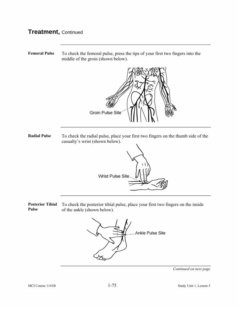
MCI Course 1141B 1-75 Study Unit 1, Lesson 5
Treatment, Continued
Femoral Pulse To check the femoral pulse, press the tips of your first two fingers into the
middle of the groin (shown below).
Radial Pulse To check the radial pulse, place your first two fingers on the thumb side of the
casualty’s wrist (shown below).
Posterior Tibial Pulse
To check the posterior tibial pulse, place your first two fingers on the inside of the ankle (shown below).
Continued on next page
MCI Course 1141B 1-76 Study Unit 1, Lesson 5
Treatment, Continued
Bleeding Human life cannot continue without an adequate volume of blood circulating
through the body to carry oxygen to the tissues. An important first aid measure is to stop the bleeding to prevent the loss of blood. Look for spurts of blood or blood-soaked clothes. Also, check for both entry and exit wounds. If the casualty is bleeding from an open wound, stop the evaluation and begin first-aid procedures.
Shock Shock means there is an inadequate blood flow to the vital tissues and organs.
Shock that remains uncorrected may result in death even though the injury or condition causing the shock would not otherwise be fatal. Shock can result from many causes such as loss of blood, loss of fluid from deep burns, pain, and reaction to the sight of a wound or blood. First aid includes preventing shock, since the casualty’s chances of survival are much greater if he does not develop shock. If the signs and symptoms of shock are present, stop the evaluation and begin first aid measures immediately. The following are the signs and symptoms of shock: • Sweaty, but cool skin (clammy skin) • Paleness of skin (dark-skinned service members look for a grayish cast to
the skin) • Restlessness or nervousness • Thirst • Loss of blood (bleeding) • Confusion (not aware of surroundings) • Faster than normal breathing rate • Blotchy or bluish skin, especially around the mouth • Nausea or vomiting
Continued on next page

MCI Course 1141B 1-77 Study Unit 1, Lesson 5
Treatment, Continued
Shock, continued
When treating a casualty, assume that shock is present or will occur shortly. Waiting until actual signs and symptoms of shock are noticeable, the rescuer may jeopardize the casualty’s life. Follow the steps below to treat a casualty for shock:
Step Action
1 Move the casualty to cover if cover is available and the situation permits.
2 Lay the casualty on his or her back. 3 Elevate the casualty’s feet higher than the level of his or her heart.
Use a stable object or rolled up clothing so that his or her feet will not slip off. Note: Do not elevate legs if the casualty has an unsplinted broken
leg, head injury, or abdominal injury. 4 Loosen clothing at the neck, waist, or wherever it may be binding 5 Prevent chilling or overheating. The key is to maintain body
temperature. 6 Calm the casualty. Throughout the entire procedure of providing
first aid for a casualty, the rescuer should reassure the casualty and keep him or her calm.
7 When providing first aid for shock, DO NOT give the casualty any food or drink.
8 Continue to evaluate the casualty.
Fractures Check for the following signs and symptoms of a back or neck injury and
perform first aid procedures if necessary. • Pain or tenderness of the back or neck area • Cuts or bruises on the back or neck area • Inability of a casualty to move or decreased sensation to extremities
(paralysis or numbness) • Ask about ability to move (paralysis) • Numbness • Unusual body or limb position
Note: Immobilize any casualty suspected of having a back or neck injury.
Continued on next page

MCI Course 1141B 1-78 Study Unit 1, Lesson 5
Treatment, Continued
Burns Burns that are found, especially to the upper torso and face, may cause
respiratory complications. When evaluating the casualty, • Look carefully for reddened, blistered, or charred skin. • Check for singed clothing. • Look for singed nose hair. • Look for soot around the nostrils. • Listen for abnormal breathing sounds or difficulty breathing.
Head Injury If a head injury is suspected, continue to watch for the following signs and
symptoms, which would require performance of rescue breathing, first aid measures for shock, or control of bleeding: • Unequal pupils • Fluid from the ear(s), nose, mouth, or injury site • Slurred speech • Confusion • Sleepiness • Loss of memory or consciousness • Staggering in walking • Headache • Dizziness • Nausea or vomiting • Paralysis • Convulsions or twitches • Bruising around the eyes and behind the ears

MCI Course 1141B 1-79 Study Unit 1, Lesson 5
Automated External Defibrillator
Description An automated external defibrillator (AED) (shown below) is a portable
electronic device that automatically diagnoses the potentially life-threatening cardiac arrhythmias of ventricular fibrillation and ventricular tachycardia in a patient. It is used to apply electrical therapy, which stops the arrhythmia, allowing the heart to re-establish an effective rhythm. Unlike regular defibrillators, an AED requires little training. The AED automatically diagnoses the heart rhythm and determines if a shock is needed. Automatic models will administer the shock without the user’s command. Semi-automatic models will tell the user that a shock is needed, but the user must tell the machine to do so, usually by pressing a button. Note: The use of AEDs is taught in many first aid, first responder, and basic
life support level CPR classes.
MCI Course 1141B 1-80 Study Unit 1, Lesson 5
Pole Top Rescue
Purpose The purpose of pole top rescue is to remove a casualty from a power pole
quickly and safely. There are many reasons why you may need to rescue a person from a pole and lower them to the ground. No matter what the reason, if a casualty is unable to remove him or herself from a pole, you must perform a pole top rescue. The following are four basic steps in accomplishing the one-man concept of pole top rescue:
Step Action
1 Evaluate the situation. 2 Provide personal protection. 3 Climb to the rescue position. 4 Lower the casualty to the ground.
Evaluate the Situation
Call the person on the pole and ask if they are okay or if they require assistance. If there is no response, or if the casualty seems stunned or dazed, go to their aid. Time is extremely important so you evaluate your surroundings. Determine if the pole is split, cracked, or on fire. Also, determine if the casualty is in contact with a live conductor. Remember to look at the whole scene, not just the casualty.
Provide Personal Protection
Your safety is important to the rescue mission because there will be no rescue without you. Your personal protective equipment must be in good condition to attempt a rescue. The following equipment is necessary for conducting a pole top rescue and is not limited to the following: • Personal climbing equipment (hooks, body belt, and safety straps) • Rescue rope that is ½ inch in diameter and twice the height of the highest
cross arm on the base plus an additional 10 feet • Knife • Rubber protective equipment (boots, gloves, and apron)
Continued on next page

MCI Course 1141B 1-81 Study Unit 1, Lesson 5
Pole Top Rescue, Continued
Climb to the Rescue Position
Carefully begin to climb the pole to a position that is slightly above the casualty and to the side, which will place you in the best position to work with the casualty. If necessary, clear the casualty and your position of any hazards and then reposition yourself to determine the casualty’s condition.
Lower the Casualty to the Ground
After determining that the casualty needs to be lowered to the ground, follow the steps below:
Step Action
1 Position the rescue line over the cross arm or other part of the pole structure. Note: Placement is dictated by the position of the casualty
whether you are right- or left-handed, and your position in relation to the casualty.
2 Place the rescue line 2 to 3 feet from the pole for the best operation.
3 Wrap the short end of the line around the fall line twice. 4 Pass the short end around the casualty’s chest. 5 Tie the short end in 3 half hitches. The knot should be in front of
the casualty, near one armpit and high on the chest. 6 Remove the slack in the hand line by pulling on it. 7 Take a firm grip on the fall line with one hand and use the other
hand to cut the casualty’s safety strap on the side opposite the desired swing. WARNING: Do not accidentally cut your own safety strap when
cutting the casualty’s safety strap. 8 Lower the casualty and control their descent by tightening and
loosening the two twists in the rope with one hand. Use the other hand to guide the casualty through any lower obstructions.

MCI Course 1141B 1-82 Study Unit 1, Lesson 5
(This page intentionally left blank.)
MCI Course 1141B 1-83 Study Unit 1, Lesson 5 Exercise
Lesson 5 Exercise
Directions Complete items 1 through 8 by performing the action required. Check your
answers against those listed at the end of this lesson.
Item 1 A low voltage alternating current of 110 to 120 volts at 60 hertz traveling
through the chest for a fraction of a second may induce which type of electrical shock effect? a. Burns b. Neurological c. Ventricular fibrillation d. Psychological
Item 2 Which item below would be the best equipment to remove a casualty from an
electrical circuit? a. Aluminum pipe b. Copper or steel grounding rod c. Tire iron d. Wood
Item 3 Which is the correct sequence of steps for recovering an electrical shock
casualty? 1. After the casualty is free of contact with the electrical source, move the
person a short distance away from the source. 2. Send for help as soon as possible. 3. If you cannot turn off the electrical power, pull, push, or lift the casualty to
safety using a wooden pole, rope, or other insulated material. 4. If possible, turn off the electrical power at the nearby switch. Remember
do not waste time looking for the switch if the location is unknown. a. 1, 2, 3, 4 b. 4, 3, 2, 1 c. 2, 4, 3, 1 d. 4, 2, 3, 1
Continued on next page

MCI Course 1141B 1-84 Study Unit 1, Lesson 5 Exercise
Lesson 5 Exercise, Continued
Item 4 When checking the breathing of an electrical shock casualty, what is the first
step? a. Determine if the casualty is breathing. b. Clear the airway. c. Check for fractures. d. Ventilate the casualty.
Item 5 When attempting to perform rescue breathing, what preliminary steps do you
take? a. Look at the casualty’s arm, listen for breathing sound, and feel for breath
on the side of your face. b. Look for the rise and fall of the casualty’s chest, listen for breathing
sound, and feel for breath on the side of your face. c. Look for the rise and fall of the casualty’s chest, listen for verbal response,
and feel for the breath on the side of your face. d. Look for the rise and fall of the casualty’s chest, listen for verbal response,
and feel for the pulse.
Item 6 If the casualty has a severe jaw fracture, which method would you use?
a. Pulse b. Mouth-to-mouth c. Jaw thrust d. Mouth-to-nose
Continued on next page

MCI Course 1141B 1-85 Study Unit 1, Lesson 5 Exercise
Lesson 5 Exercise, Continued
Item 7 In most cases, an electrical shock casualty will require treatment for shock.
When treating for shock, lay the casualty on his or her a. back and keep their feet level in regards to the height of their heart. b. stomach and keep their feet level in regards to the height of their heart. c. stomach and elevate their feet higher than the level of their heart. d. back and elevate their feet higher than the level of their heart.
Item 8 When conducting a pole top rescue, evaluate the situation, _______________,
climb to the rescue position, and lower the casualty to the ground. a. provide personal protection b. call for help c. check for confusion d. determine plan of action
Continued on next page

MCI Course 1141B 1-86 Study Unit 1, Lesson 5 Exercise
Lesson 5 Exercise, Continued
Answers The table listed below lists the answers to the exercise items. If you have any
questions about these items, refer to the reference page.
Item Number Answer Reference Page 1 c 1-66 2 d 1-69 3 d 1-69 4 a 1-70 5 b 1-72 6 d 1-74 7 d 1-77 8 a 1-80

MCI Course 1141B 2-1 Study Unit 2, Lesson 1
STUDY UNIT 2
ELECTRICAL EQUIPMENT
Overview
Scope Now that we have an understanding of what electricity is and how it is
created, we will focus on its use in our daily lives. In this study unit, we will learn the different uses of the power source, how resistance and conductance factor in determining the type of wires that are required to provide us with electricity, and the different connectors used around the world.
In This Study Unit
This study unit contains the following lessons:
Lesson See Page
Power Sources 2-3 Electrical Wire 2-21 International Electricity 2-45

MCI Course 1141B 2-2 Study Unit 2, Lesson 1
(This page intentionally left blank.)

MCI Course 1141B 2-3 Study Unit 2, Lesson 1
LESSON 1
POWER SOURCES
Introduction
Scope Centralized power generation became possible when it was recognized that
alternating-current power lines could transport electricity at very low costs across great distances by taking advantage of the ability to raise and lower the voltage using power transformers. Electricity has been generated for powering human technologies since 1881 from various sources of energy. The first power plants were run on water power or coal. Today we rely mainly on coal, nuclear power, natural gas, hydroelectric, and petroleum with a small amount from solar energy, tidal harness, wind generators, and geothermal sources. Electricity is produced from power sources that can be either natural or mechanical. Before you use electricity, understand the different ways it can be produced and the impact it has on us. In this lesson, we will cover the different types of power sources that are available to aid an electrician in distributing electrical power.
Learning Objectives
Upon completion of this lesson, you will be able to • Identify renewable energy sources for producing electricity. • Identify non-renewable energy sources for producing electricity.
In This Lesson This lesson contains the following topics:
Topic See Page Introduction 2-3 Renewable Energy Sources 2-4 Non-Renewable Energy Sources 2-9 Lesson 1 Exercise 2-17

MCI Course 1141B 2-4 Study Unit 2, Lesson 1
Renewable Energy Sources
Definition A renewable energy source, referred to as green energy sources, derives from
resources that are regenerative, or for all practical purposes that cannot be depleted. Renewable energy sources contribute approximately 29 percent of electrical energy used worldwide. Recently, the mass production of electricity using renewable energy sources has become more commonplace. This is because of the climate change due to pollution; exhaustion of fossil fuels; environmental, social, and political risks of fossil fuels; and the use of nuclear power. Many countries and organizations promote renewable energy through taxes and subsidies. The following are three traditional ways to produce electricity from renewable energy sources: • Solar • Wind • Water Mass production of electricity from renewable energy flow requires technology that harnesses the power of natural phenomena, such as sunlight, wind, tides, and geothermal heat. Each of these sources has unique characteristics which influence how and where they are used.
Solar Solar energy is collected from sunlight for generating electricity. Most fossil
and renewable energy sources derives from “solar energy” so some may ascribe much broader meanings to the term. Electricity can be generated from the sun in several ways. Photovoltaics (PV) are developed for small and medium-sized applications, such as the calculator powered by a single solar cell to a PV power plant.
Continued on next page

MCI Course 1141B 2-5 Study Unit 2, Lesson 1
Renewable Energy Sources, Continued
Photovoltaics (PV)
A solar cell of photovoltaic (PV) cell is a device that converts light into electricity into electrical power. The PV is best known as a method for generating solar power by using solar cells packaged in photovoltaic modules. To explain the photovoltaic solar panel more simply, photons from sunlight knock electrons into a higher state of energy creating electricity. Solar cells produce direct current electricity from light so to use it for a house, you would need an inverter to convert the electricity from direct current to alternating current.
PV Development
Charles Fritts constructed the first working solar cells in 1883. Photovoltaic was first used in the Vanguard Satellite in 1958. Since that great accomplishment, PV has become the established source of power for all satellites. Photovoltaic has also been used for offshore oil rigs and lighthouses. The manufacturing of photovoltaic cells has expanded dramatically in recent years. Photovoltaic production has doubled every 2 years, increasing by an average of 48 percent each year since 2002, making it the world’s fastest growing energy technology.
Solar Reliability
Weather is a condition that can affect all aspects of renewable energy. Solar electricity is not available at night and may be less available due to weather conditions, such as clouds and rain. It is important to note that there are solar panels still capable of producing reduced amounts of power during certain types of inclement weather, like rain that absorbs solar rays to produce energy.
Continued on next page

MCI Course 1141B 2-6 Study Unit 2, Lesson 1
Renewable Energy Sources, Continued
Wind Wind power is the conversion of wind energy into useful form, such as
electricity, using wind turbines. In windmills, wind energy is directly used to crush grain or to pump water. Wind power is produced in large-scale wind farms connected to electrical grids, as well as in individual turbines for providing electricity to isolated locations. Wind energy is plentiful, renewable, widely distributed, and reduces greenhouse gas emissions when it displaces fossil-fuel-derived electricity.
Potential Turbine Power
The power in the wind can be extracted by allowing it to blow past moving blades that exert torque on a rotor. The amount of power transferred is directly proportional to the density of the air, the area swept out by the rotor, and the cube of the wind speed. Where P = power in watts, α = an efficiency factor determined by the design of the turbine, ρ = mass density of air in kilograms per cubic meter, r = radius of the wind turbine in meters, and v = velocity of the air in meters per second. As the wind turbine extracts energy from the airflow, the air is slowed down, which causes it to spread out. Albert Betz, a German physicist, determined that a wind turbine can extract at most 59 percent of the energy that would otherwise flow through the turbine’s cross section, that is α can never be higher than 0.59 in the equation below. The Betz limit applies regardless of the design of the turbine.
32
21 vrP αρπ=
Continued on next page

MCI Course 1141B 2-7 Study Unit 2, Lesson 1
Renewable Energy Sources, Continued
Wind Reliability
Windiness varies, and an average value for a given location does not indicate the amount of energy a wind turbine could produce there. To assess the frequency of wind speeds at a particular location, a probability distribution function is often fit to observe the data. Different locations will have different wind speed distributions. The consequence is that wind energy does not have as consistent an output as fuel-fired power plants; utilities that use wind power must provide backup generation for times that the wind is weak, especially when the jet stream or the frequency of the wind is a variable that must be considered.
Water Water can produce high yields of energy because water is approximately
1,000 times denser than air. Even a slow flowing stream of water or moderate sea swell can yield considerable amounts of energy. The following are many forms of water used to make energy: • Hydroelectric energy (We will focus on this one.) • Tidal power • Tidal stream power • Wave power
Hydroelectric Power (Hydro-electricity)
Hydroelectricity is produced by hydropower. This renewable source of energy produces no waste, and does not produce carbon dioxide (CO2), which contributes to greenhouse gases. Hydroelectricity supplies about 715,000 MWe or 19 percent of world electricity (16 percent in 2003), accounting for over 63 percent of the total electricity from renewable sources in 2005. Most hydroelectric power comes from the potential energy of dammed water driving a water turbine and generator. In this case, the energy extracted from the water depends on the volume and the difference in height between the source and the water’s outflow. This height difference is called the head. The amount of potential energy in water is proportional to the head. To obtain very high head, water for a hydraulic turbine may be run through a large pipe called a penstock. An example of hydroelectric power is shown on the next page.
Continued on next page

MCI Course 1141B 2-8 Study Unit 2, Lesson 1
Renewable Energy Sources, Continued
Hydroelectric Power (Hydro-electricity), continued
Hydroelectric Power Reliability
Overall, no conditions can cause unreliable or uninterrupted power supply, but it is important to note that these types of power sources can cause severe damage. Failures of large dams, while rare, are potentially serious. The Banqiao Dam failure in Southern China resulted in the deaths of 171,000 people and left millions homeless. Dams may be subject to enemy bombardment during wartime, sabotage and terrorism. Smaller dams and micro-hydro facilities are less vulnerable to these threats.
The creation of a dam in a geologically inappropriate location may cause disasters like the one of the Vajont Dam in Italy, where almost 2,000 people died in 1963.
MCI Course 1141B 2-9 Study Unit 2, Lesson 1
Non-Renewable Energy Sources
Definition A non-renewable energy source, referred to as brown energy sources, is a
natural resource that cannot be re-made, re-grown or regenerated on a scale comparative to its consumption. It exists in a fixed amount that is being renewed or is used up faster than it can be made by nature. Fossil fuels (such as coal, petroleum, and natural gas) and nuclear power are non-renewable resources, as they do not naturally re-form at a rate that makes the way we use them sustainable and consumer materials to produce electricity. A renewable resource differs in that it may be used, but not used up. This is as opposed to natural resources such as timber, which re-grows naturally and can, in theory, be harvested and sustain ably at a constant rate without depleting the existing resource pool and resources such as metals. Although they are not replenished, they are not destroyed when used and can be recycled.
Fossil Fuels Fossil fuels are formed from the organic remains of prehistoric plants and
animals, and they currently provide approximately 66 percent of the world’s electrical power and 95 percent of the world’s total energy demands. The following are different types of fossil fuels: • Coal • Oil • Natural Gas
Coal Coal is a readily combustible black or brownish-black rock. It is a
sedimentary rock, but the harder forms, such as anthracite coal, can be regarded as metamorphic rocks because of later exposure to elevated temperature and pressure. Coal is composed primarily of carbon along with assorted other elements, including sulfur. This is the largest single source of fuel for the generation of electricity worldwide, as well as the largest worldwide source of carbon dioxide emissions, slightly ahead of petroleum and about double that of natural gas. Coal is extracted from the ground by coal mining, either underground mining or open-pit mining or strip mining (surface mining).
Continued on next page

MCI Course 1141B 2-10 Study Unit 2, Lesson 1
Non-Renewable Energy Sources, Continued
Coal, continued The table below shows the four main types of coal.
Coal Type Description Lignite Lignite is the lowest rank of coal with the lowest energy
content. Lignite coal deposits tend to be relatively young coal deposits that were not subjected to extreme heat or pressure. Lignite is burned mainly at power plants for electricity.
Sub bituminous Sub bituminous coal has a higher heating value than lignite. Sub bituminous coal typically contains more carbon than lignite. Most sub bituminous coal in the U.S. is at least 100 million years old.
Bituminous Bituminous coal has two to three times the heating value of lignite. This coal was formed under high heat and pressure and is between 100- to 300-million years old. The bituminous coal is the most abundant rank of coal in the United States, accounting for about half of U.S. coal production. Bituminous coal is used to generate electricity, but is also the important raw material used for steel and the iron industries.
Anthracite Anthracite coal has a heating value slightly lower than bituminous coal. This coal is rare in the United States, accounting for less than one-half of a percent of the coal mined in the United States.
Coal and Electrical Power
About 92 percent of the coal used in the United States is for generating electricity. The remaining percent goes to industries that use it for steel, cement, and paper. Coal is used to generate roughly half of all electricity produced in the United States. Many other countries like India and China use coal as the main source for producing the electricity in their respective countries. Coal is the fastest growing energy source in the world, with coal increasing by 25 percent for a 3-year period from 2001 and ending in 2004.
Continued on next page

MCI Course 1141B 2-11 Study Unit 2, Lesson 1
Non-Renewable Energy Sources, Continued
Coal Process When coal is used for electricity generation, it is usually pulverized and then
burned in a furnace with a boiler. The furnace heat converts boiler water to steam, which is used to spin turbines that turn generators and create electricity. The thermodynamic efficiency of this process has been improved over time. “Standard” steam turbines have topped out with some of the most advanced reaching about 35 percent thermodynamic efficiency for the entire process, which means 65 percent of the coal energy is rejected as waste heat into the surrounding environment.
Coal Environmental Effects
Emissions from coal-fired power plants represent one of the two largest sources of carbon dioxide emissions, believed to be the cause of global warming. Coal mining and abandoned mines also emit methane, another purported cause of global warming. Since the carbon content of coal is higher than oil, burning coal is a serious threat to the stability of the global climate, as this carbon forms CO2 when burned. Many other pollutants are present in coal power station emissions, as solid coal is more difficult to clean than oil, which is refined before use.
Oil Petroleum or crude oil is a naturally occurring, flammable liquid found in
rock formations in the Earth consisting of a complex mixture of hydrocarbons of various lengths, plus other organic compounds. The proportion of hydrocarbons in the mixture is highly variable and ranges from as much as 97 percent by weight in the lighter oils to as little as 50 percent in the heavier oils. Petroleum is used mostly, by volume, for producing fuel oil and gasoline (petrol), both important “primary energy” sources. Eighty-four percent by volume of the hydrocarbons present in petroleum is converted into energy-rich fuels (petroleum-based fuels), including gasoline, diesel, jet, heating, and other fuel oils.
Oil Process Oil is the only natural commercial fossil fuel used for producing electricity
from the time it is extracted by burning it to create steam, which turns turbines to produce electricity.
Continued on next page

MCI Course 1141B 2-12 Study Unit 2, Lesson 1
Non-Renewable Energy Sources, Continued
Oil Environmental Effects
Burning oil releases carbon dioxide (CO2) into the atmosphere, which has been argued to contribute to global warming. Per joule, oil produces 15 percent less CO2 than coal, but 30 percent more than natural gas. However, the unique role of oil as the main source of transportation fuel makes reducing its CO2 emissions a difficult problem. Large power plants can, in theory, eliminate their CO2 emissions by techniques such as carbon sequestering or even use them to increase oil production through enhanced oil recovery techniques.
Natural Gas Natural gas is a gaseous fossil fuel consisting primarily of methane; however,
it includes significant quantities of ethane, propane, butane, and pentane. Heavy hydrocarbons are removed later as condensate, as well as carbon dioxide, nitrogen, helium and hydrogen sulfide. It is found in oil fields (associated) either dissolved or isolated in natural gas fields (non-associated), and in coal beds (as coal bed methane). Natural gas is often informally referred to simply as gas, especially when compared to other energy sources such as electricity. Before natural gas can be used as a fuel, it must undergo extensive processing to remove almost all materials other than methane. The by-products of that processing include the following: • Ethane • Propane • Butanes • Pentanes • Higher molecular weight hydrocarbons • Elemental sulfur • Helium • Nitrogen
Power Generation
Natural gas is a major source of electricity generation using gas turbines and steam turbines. Particularly, high efficiencies can be achieved through combining gas turbines with a steam turbine in combined cycle mode. Industrial gas turbines range in size from truck-mounted mobile plants to enormous, complex systems. They can be particularly efficient up to 60 percent when a heat recovery, steam generator powers a conventional steam turbine in a combined cycle configuration recovers waste heat from the gas turbine.
Continued on next page

MCI Course 1141B 2-13 Study Unit 2, Lesson 1
Non-Renewable Energy Sources, Continued
Natural Gas Environmental Effects
Natural gas burns cleaner than other fossil fuels, such as oil and coal, which produces less carbon dioxide per unit energy released. For an equivalent amount of heat, burning natural gas produces about 30 percent less carbon dioxide than burning petroleum and about 45 percent less than burning coal. Combined cycle power generation using natural gas is thus the cleanest source of power available using fossil fuels. This technology is widely used wherever gas can be obtained at a reasonable cost.
Nuclear Power Nuclear power is nuclear technology involving the controlled use of nuclear
fission to release energy for work including propulsion, heat, and the generation of electricity. A controlled nuclear chain reaction that creates heat produces nuclear energy, which boils water, produces steam, and drives a steam turbine. The turbine can be used for mechanical work and generate electricity.
Global Use As of 2004, nuclear power provided 6.5 percent of the world’s energy and
15.7 percent of the world's electricity, with the United States, France, and Japan accounting for 57 percent of nuclear generated electricity. As of 2007, the IAEA reported there are 439 nuclear power reactors operating in the United States, and 31 operating in other countries.
The United States produces the most nuclear energy, with nuclear power providing 20 percent of the electricity it consumes, while France produces the highest percentage of its electrical energy from nuclear reactors, 80 percent as of 2006. In the European union as a whole, nuclear energy provides 30 percent of their electricity.
Continued on next page

MCI Course 1141B 2-14 Study Unit 2, Lesson 1
Non-Renewable Energy Sources, Continued
Global Use, continued
Many countries remain active in developing nuclear power, including Japan, China and India, all actively developing both fast and thermal technology. The illustration below shows a nuclear power plant.
Nuclear Power Process
Conventional thermal power plants all have a fuel source to provide heat. For a nuclear power plant, this heat is provided by nuclear fission inside the nuclear reactor. When a neutron strikes a relatively large fissile atomic nucleus, it forms two or more smaller nuclei as fission products, releasing energy and neutrons in a process called nuclear fission. The neutrons then trigger further fission. When this nuclear chain reaction is controlled, the energy released can be used to heat water, produce steam and drive a turbine that generates electricity. While a nuclear power plant uses the same fuel, uranium-235 or plutonium-239, a nuclear explosive involves an uncontrolled chain reaction, and the rate of fission in a reactor is not capable of reaching sufficient levels to trigger a nuclear explosion because commercial reactor grade nuclear fuel is not enriched to a high enough level. Naturally, found uranium is less than 1 percent U-235, the rest being U-238. Most reactor fuel is enriched to only 3 to 4 percent, but some designs use natural uranium or highly enriched uranium.
Continued on next page

MCI Course 1141B 2-15 Study Unit 2, Lesson 1
Non-Renewable Energy Sources, Continued
Nuclear Power Environmental Effects
The primary environmental impacts of nuclear power are damage through uranium mining, radioactive effluent emissions, and waste heat. Like renewable sources, the majority of life cycle studies have found that indirect carbon emissions from nuclear power are many times less than comparable fossil fuel plants. Nuclear generation does not directly produce sulfur dioxide, nitrogen oxides, mercury or other pollutants associated with the combustion of fossil fuels.
Other issues include disposal of nuclear waste, with high-level waste proposed to go in deep geological repositories and nuclear decommissioning.

MCI Course 1141B 2-16 Study Unit 2, Lesson 1
(This page intentionally left blank.)

MCI Course 1141B 2-17 Study Unit 2, Lesson 1 Exercise
Lesson 1 Exercise
Directions Complete exercise items 1 through 6 by performing the action required.
Check your answers against those listed at the end of this lesson.
Item 1 Energy derived from resources that are regenerative or unable to be depleted
is called __________ energy sources. a. brown b. non-renewable c. nuclear d. renewable
Item 2 The three most traditional types of renewable energy sources are
a. solar, water, and wind. b. solar, water, and wave. c. nuclear, water, and wind. d. nuclear, water, and wave.
Item 3 Which renewable energy source is collected from sunlight for generating
electricity? a. Wind b. Hydroelectric power c. Water d. Solar
Item 4 A ________________ energy source is a natural resource that cannot be re-
made, re-grown, or regenerated on a scale comparative to its consumption. a. green b. non-renewable c. renewable d. non-solar
Continued on next page

MCI Course 1141B 2-18 Study Unit 2, Lesson 1 Exercise
Lesson 1 Exercise, Continued
Item 5 Which non-renewable energy source is the fastest growing energy source in
the world producing electricity? a. Coal b. Natural Gas c. Oil d. Nuclear
Item 6 Which non-renewable energy source is the only natural commercial fossil fuel
used for producing electricity from the time it is extracted by burning it to create steam, which turns turbines to produce electricity? a. Coal b. Natural Gas c. Oil d. Nuclear

MCI Course 1141B 2-19 Study Unit 2, Lesson 1 Exercise
Lesson 1 Exercise, Continued
Answers The table below lists the answers to the exercise items. If you have any
questions about these items, refer to the reference page.
Item Number Answer Reference 1 d 2-4 2 a 2-4 3 d 2-4 4 b 2-9 5 a 2-10 6 c 2-11

MCI Course 1141B 2-20 Study Unit 2, Lesson 1 Exercise
(This page intentionally left blank.)

MCI Course 1141B 2-21 Study Unit 2, Lesson 2
LESSON 2
ELECTRICAL WIRE
Introduction
Scope As a Marine electrician, you must know how important it is to select the
proper wire when providing electrical support and how a wire delivers electricity when requested. In this lesson, we will compare conductance to resistance, identify conductors and resistors, understand the factors that determine resistance in a conductor, and know how to read the American Wire Gauge Chart. We will also identify the types of stranded wire and the methods to strip wire.
Learning Objectives
Upon completion of this lesson, you will be able to
• Identify conductance.
• Identify materials that are good conductors.
• Identify the four factors that determine resistance in a conductor.
• Identify resistance.
• Identify materials used to make good resistors.
• Calculate the resistance of a wire.
• Identify the American Wire Gauge Chart.
• Identify the different types of stranded wire.
• Identify the methods to strip wire from its protective sheathing.
Continued on next page

MCI Course 1141B 2-22 Study Unit 2, Lesson 2
Introduction, Continued
In This Lesson This lesson contains the following topics:
Topic See Page Introduction 2-21 Conductance 2-23 Resistance 2-24 American Wire Gauge 2-29 Wire 2-35 Lesson 2 Exercise 2-41
MCI Course 1141B 2-23 Study Unit 2, Lesson 2
Conductance
Definition Conductance is the measure of a material’s ability to conduct an electric
current. In addition, it is the reciprocal of electrical resistance. Conductance is well known that some materials, especially metals, permit electrical currents to easily flow through them. The materials whose atomic structures readily allow the transfer of free electrons are referred to as good conductors of electricity.
Conductors The following conductors are capable of conducting electricity:
Conductors Description
Silver The best of all conductors, but is seldom used because it is expensive
Copper Almost as good as silver, relatively inexpensive, and serves for most types of wiring
Aluminum A fairly good conductor used where weight is an important factor
It is important to realize that not all materials can be so easily classified. The degree of conductivity varies over an extremely wide range. Conductors merely represent two extremes between which great varieties of materials are classified as poor conductors or semiconductors.
Factors Even with all the possibilities of absolute perfection of a material to conduct
electricity, every conductor, no matter how good, still offers some resistance. A conductor’s resistance depends on the following four factors: • Type of material • Length of conductor • Cross sectional area or diameter • Temperature

MCI Course 1141B 2-24 Study Unit 2, Lesson 2
Resistance
Definition Electrical resistance is a measure of the degree to which an object opposes
electric current through it. Its reciprocal quantity is electrical conductance. Electrical resistance shares some conceptual parallels with the mechanical notion of friction. The unit of electrical resistance is the ohm, symbol Ω. The resistance of an object determines the amount of current through the object for a given potential difference across the object. Conductance is related to resistance by the equation below. R is the resistance of the object, measured in ohms. V is the potential difference across the object, measured in volts. I, measured in amperes, is the electric current through the object.
IVR =
Note: For a wide variety of materials and conditions, the electrical resistance
does not depend on the amount of current through or the amount of voltage across the object, meaning that the resistance (R) is constant.
Example If a certain metal has the capability of 120 volts of pressure to push 6 amps,
then its resistance will be 20 ohms of resistance.
Continued on next page

MCI Course 1141B 2-25 Study Unit 2, Lesson 2
Resistance, Continued
Resistance of Materials
The resistance rating of different materials is based on a comparison of the number of ohms measured in a standard-sized sample of material. In the metric system, the standard is one-centimeter cube whose resistance is measured in millionths of an ohm or microhms. In the English system of measurement, the standard of resistivity is called the mil-foot. This standard is based on the resistance of a piece of wire one-foot long with a diameter of .001 inch. Some of the more commonly used resistors for conducting electricity are shown in the table below.
Resistors Ohms of Resistance per Mil-foot Silver 9.6
Copper 10.4 Copper-clad Aluminum 15.2
Aluminum 17 Tungsten 33
Brass 42 Iron 60 Steel 75
Nichrome 600
Length of a Conductor
The resistance of any conductor is directly proportional to its length. For example, if 50 feet of wire has a resistance of 1 ohm, then 100 feet of the same wire will have a resistance of 2 ohms. The longer the wire, the more resistance it has. This should be taken into account whenever electricians plan the installation of a long supply line.
Continued on next page
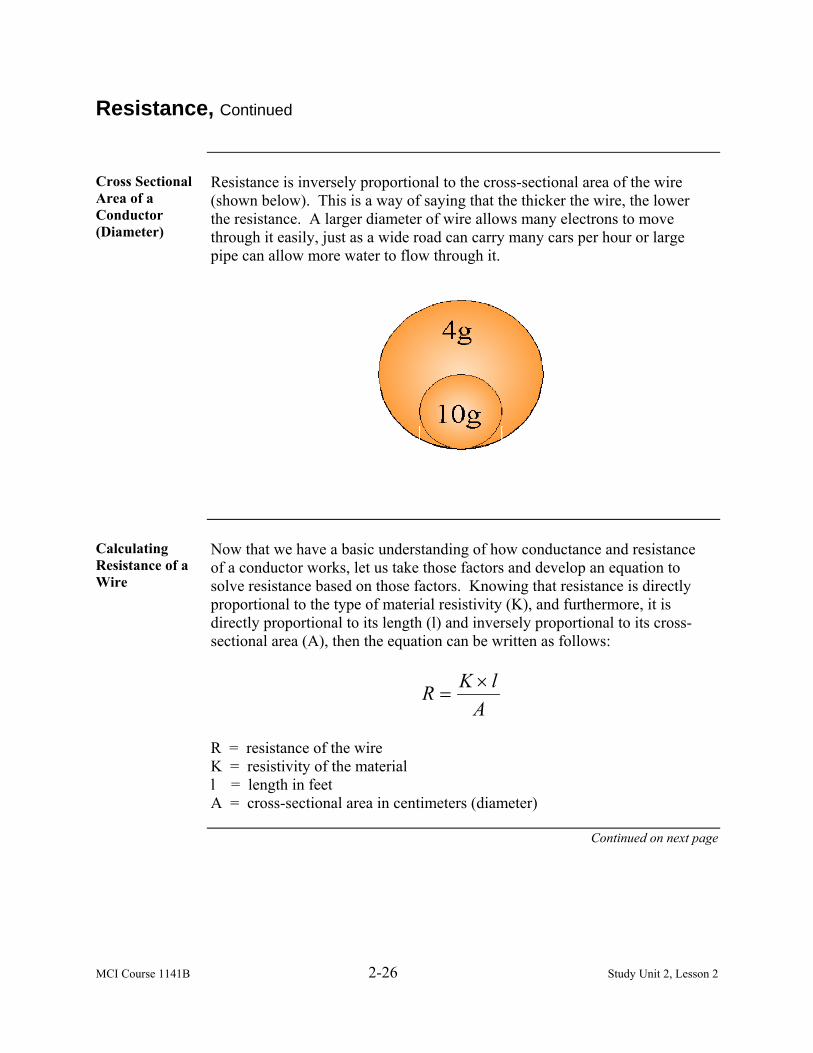
MCI Course 1141B 2-26 Study Unit 2, Lesson 2
Resistance, Continued
Cross Sectional Area of a Conductor (Diameter)
Resistance is inversely proportional to the cross-sectional area of the wire (shown below). This is a way of saying that the thicker the wire, the lower the resistance. A larger diameter of wire allows many electrons to move through it easily, just as a wide road can carry many cars per hour or large pipe can allow more water to flow through it.
Calculating Resistance of a Wire
Now that we have a basic understanding of how conductance and resistance of a conductor works, let us take those factors and develop an equation to solve resistance based on those factors. Knowing that resistance is directly proportional to the type of material resistivity (K), and furthermore, it is directly proportional to its length (l) and inversely proportional to its cross-sectional area (A), then the equation can be written as follows:
AlKR ×
=
R = resistance of the wire K = resistivity of the material l = length in feet A = cross-sectional area in centimeters (diameter)
Continued on next page
MCI Course 1141B 2-27 Study Unit 2, Lesson 2
Resistance, Continued
Challenge Using a copper wire with a cross sectional area of 4,107 circular mils, find the
resistance of 175 feet of this wire? We know the following: K = 10.4 (found in the previous table on page 2-25 the resistivity of the
copper wire) L = 175 feet A = 4,107
Answer The equation should look like this:
AlKR ×
=
107,41754.10 ×
=R
107,4820,1
=R
Ω= 443.R or R =.443 ohms
Temperature on Resistance
Resistance depends not only on the length, area, and kind of material, but also on the temperature of the material. The temperature of a conductor has a less obvious effect on the resistance of the conductor. To understand the effect, picture what happens in a conductor as it is heated. Remember, heat on the atomic or molecular scale is a direct representation of the vibration of the atoms or molecules. Higher temperature means more vibrations.
Continued on next page
MCI Course 1141B 2-28 Study Unit 2, Lesson 2
Resistance, Continued
Example Imagine a hallway full of people. Half of the people (the electrons) are trying
to move in the same direction you are and the other half (the protons) are evenly spaced but stationary in the hallway. This would represent a cold wire. Since the wire is cold, the protons are not vibrating much so the electrons can run between them rapidly. As the conductor (hallway) heats up, the protons start vibrating and moving slightly out of position. As their motion becomes more erratic, they are more likely to get in the way and disrupt the flow of the electrons. As a result, the higher the temperature is the higher the resistance.
Superconduc-tors
At extremely low temperatures, some materials have no measurable resistance. This is called superconductivity. The materials are known as superconductors. Gradually, we are creating materials that become superconductors at higher temperatures and are finding or creating materials that superconduct at room temperature.
Example Inside a superconductor, the behavior of electronics is vastly different. The
impurities and lattice are still there, but the movement of the super-conducting electrons through the obstacle course is quite different. As the superconducting electrons travel through the conductor, they pass unobstructed through the complex lattice. Because they bump into nothing and create no friction, they can transmit electricity with no appreciable loss in the current and no loss of energy. Some examples of superconductors are: • Mercury • Niobium-Tin • Lanthanum-Barium-Copper Oxide

MCI Course 1141B 2-29 Study Unit 2, Lesson 2
American Wire Gauge
Description You must know that it would be impractical having to calculate resistance for
any given length and diameter of wire. Such information has been created to give more readily available information to electricians for identifying the correct wire to use for the proper applications. American wire gauge (AWG), also known as the Brown and Sharpe wire gauge, is a standardized wire gauge system used in the United States and other countries, especially for nonferrous, electrically conducting wire. It is important to use the AWG in conjunction with the National Electrical Code (NEC) to ensure that all safety requirements are met for installing any type of wire conductor for providing electricity. The table on the following pages displays the current wire gauge chart.
Useful Information
When reading the chart, the following information may be useful: • The larger the number, the smaller the wire. • A #2 wire is nearly the size of a standard wooden pencil. • A #44 wire has a thickness or diameter of a fine hair. • Odd numbered conductors are rarely used and seldom sold. • The most prevalent wire sizes used in a home are #14 or #12. • A #14-gauge wire is the smallest wire permissible by the NEC. • Ordinary lamp cords are generally made of #16- or #18-gauge wire. • A stranded wire has the same amount of copper and the same current-
carrying capacity as a solid wire of the same size.
Standard Wire Gauge Tool
The illustration below shows a standard wire gauge tool used by electricians to determine the size or gauge of wire.
Continued on next page

MCI Course 1141B 2-30 Study Unit 2, Lesson 2
American Wire Gauge, Continued
Current Wire Gauge Chart
AWG Diameter Turns of Wire Area Copper Resistance
Copper Wire Current Rating
With 60°C Raceway
ApproximateStranded
Metric Equivalents
(inch) (mm) (per inch) (per cm) (kcmil) (mm²) (Ω/km) (mΩ/ft)[3] (A)
0000 (4/0) 0.460 11.7 2.17 0.856 212 107 0.16* 0.049* 195
000 (3/0) 0.410 10.4 2.44 0.961 168 85.0 0.2* 0.062* 165
00 (2/0) 0.365 9.27 2.74 1.08 133 67.4 0.25* 0.077* 145
0 (1/0) 0.325 8.25 3.08 1.21 106 53.5 ~0.3281 ~0.1 125
1 0.289 7.35 3.46 1.36 83.7 42.4 0.4* 0.12* 110
2 0.258 6.54 3.88 1.53 66.4 33.6 0.5* 0.15* 95
3 0.229 5.83 4.36 1.72 52.6 26.7 85 196/0.4
Continued on next page

MCI Course 1141B 2-31 Study Unit 2, Lesson 2
American Wire Gauge, Continued
AWG Diameter Turns of Wire Area Copper Resistance
Copper Wire Current Rating
With 60°C Raceway
ApproximateStranded
Metric Equivalents
(inch) (mm) (per inch) (per cm) (kcmil) (mm²) (Ω/km) (mΩ/ft)[3] (A)
5 0.182 4.62 5.50 2.16 33.1 16.8 126/0.4
6 0.162 4.12 6.17 2.43 26.3 13.3 1.5* 0.47* 55
7 0.144 3.66 6.93 2.73 20.8 10.5 80/0.4
8 0.128 3.26 7.78 3.06 16.5 8.37 2.2* 0.67* 40
9 0.114 2.91 8.74 3.44 13.1 6.63 >84/0.3
10 0.102 2.59 9.81 3.86 10.4 5.26 3.2772 0.9989 30 <84/0.3
11 0.0907 2.30 11.0 4.34 8.23 4.17 4.1339 1.26 56/0.3
12 0.0808 2.05 12.4 4.87 6.53 3.31 5.21 1.588 20
13 0.0720 1.83 13.9 5.47 5.18 2.62 6.572 2.003 50/0.25
Continued on next page

MCI Course 1141B 2-32 Study Unit 2, Lesson 2
American Wire Gauge, Continued
AWG Diameter Turns of Wire Area Copper Resistance
Copper Wire Current Rating
With 60°C Raceway
ApproximateStranded
Metric Equivalents
(inch) (mm) (per inch) (per cm) (kcmil) (mm²) (Ω/km) (mΩ/ft)[3] (A)
14 0.0641 1.63 15.6 6.14 4.11 2.08 8.284 2.525 15
15 0.0571 1.45 17.5 6.90 3.26 1.65 10.45 3.184 >30/0.25
16 0.0508 1.29 19.7 7.75 2.58 1.31 13.18 4.016 10 <30/0.25
17 0.0453 1.15 22.1 8.70 2.05 1.04 16.614 5.064 32/0.2
18 0.0403 1.02 24.8 9.77 1.62 0.823 20.948 6.385 >24/0.2
19 0.0359 0.912 27.9 11.0 1.29 0.653 26.414 8.051 <24/0.2
20 0.0320 0.812 31.3 12.3 1.02 0.518 33.301 10.15 3.3 16/0.2
21 0.0285 0.723 35.1 13.8 0.810 0.410 41.995 12.8
22 0.0253 0.644 39.5 15.5 0.642 0.326 52.953 16.14 2.1 7/0.25
Continued on next page
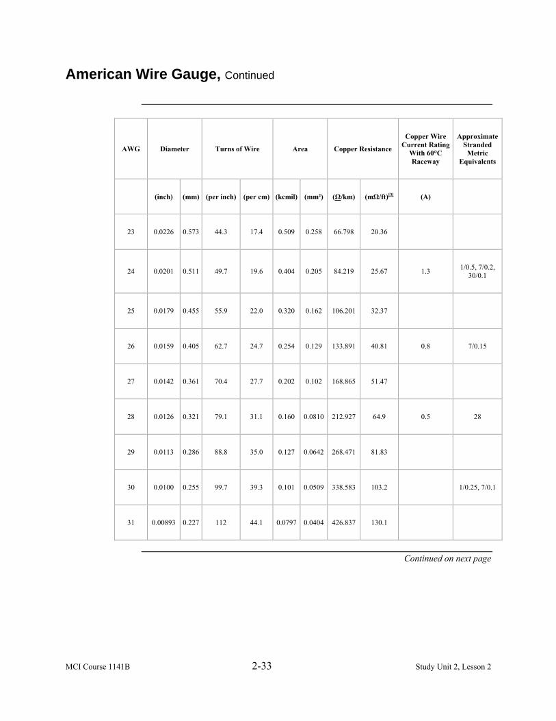
MCI Course 1141B 2-33 Study Unit 2, Lesson 2
American Wire Gauge, Continued
AWG Diameter Turns of Wire Area Copper Resistance
Copper Wire Current Rating
With 60°C Raceway
ApproximateStranded
Metric Equivalents
(inch) (mm) (per inch) (per cm) (kcmil) (mm²) (Ω/km) (mΩ/ft)[3] (A)
23 0.0226 0.573 44.3 17.4 0.509 0.258 66.798 20.36
24 0.0201 0.511 49.7 19.6 0.404 0.205 84.219 25.67 1.3 1/0.5, 7/0.2, 30/0.1
25 0.0179 0.455 55.9 22.0 0.320 0.162 106.201 32.37
26 0.0159 0.405 62.7 24.7 0.254 0.129 133.891 40.81 0.8 7/0.15
27 0.0142 0.361 70.4 27.7 0.202 0.102 168.865 51.47
28 0.0126 0.321 79.1 31.1 0.160 0.0810 212.927 64.9 0.5 28
29 0.0113 0.286 88.8 35.0 0.127 0.0642 268.471 81.83
30 0.0100 0.255 99.7 39.3 0.101 0.0509 338.583 103.2 1/0.25, 7/0.1
31 0.00893 0.227 112 44.1 0.0797 0.0404 426.837 130.1
Continued on next page
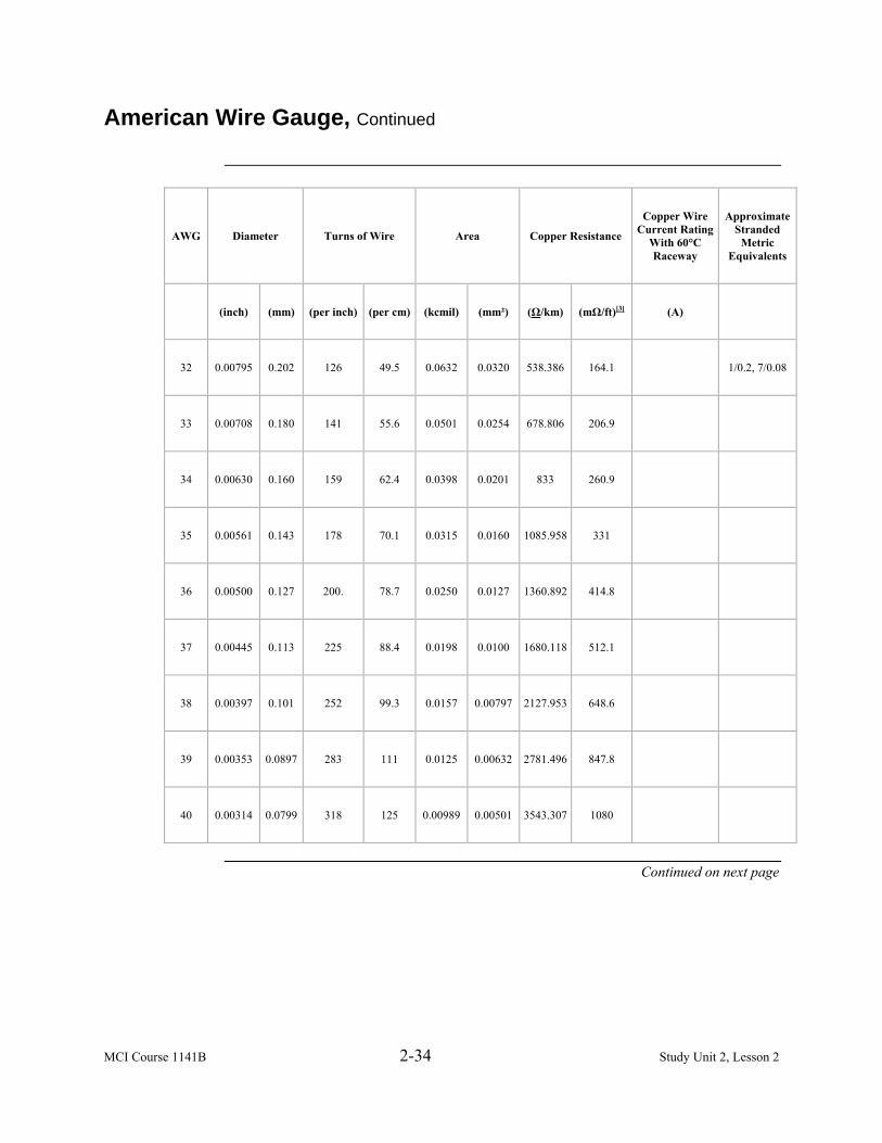
MCI Course 1141B 2-34 Study Unit 2, Lesson 2
American Wire Gauge, Continued
AWG Diameter Turns of Wire Area Copper Resistance
Copper Wire Current Rating
With 60°C Raceway
ApproximateStranded
Metric Equivalents
(inch) (mm) (per inch) (per cm) (kcmil) (mm²) (Ω/km) (mΩ/ft)[3] (A)
32 0.00795 0.202 126 49.5 0.0632 0.0320 538.386 164.1 1/0.2, 7/0.08
33 0.00708 0.180 141 55.6 0.0501 0.0254 678.806 206.9
34 0.00630 0.160 159 62.4 0.0398 0.0201 833 260.9
35 0.00561 0.143 178 70.1 0.0315 0.0160 1085.958 331
36 0.00500 0.127 200. 78.7 0.0250 0.0127 1360.892 414.8
37 0.00445 0.113 225 88.4 0.0198 0.0100 1680.118 512.1
38 0.00397 0.101 252 99.3 0.0157 0.00797 2127.953 648.6
39 0.00353 0.0897 283 111 0.0125 0.00632 2781.496 847.8
40 0.00314 0.0799 318 125 0.00989 0.00501 3543.307 1080
Continued on next page

MCI Course 1141B 2-35 Study Unit 2, Lesson 2
Wire
Definition A wire is a single, usually cylindrical, elongated string of drawn metal. The
term wire is also used more loosely to refer to a bundle of such strands, as in multi-stranded wire, which is more correctly termed a cable. Electrical wires are covered with various insulating materials, such as plastic or rubber-like polymers. There are two types of wire that an electrician should identify: • Solid • Stranded
Solid Solid wire or solid-core wire (shown below) consists of one piece of metal
wire. Solid single-strand wire is cheaper to manufacture than stranded wire and is used where there is no need for flexibility in the wire. Solid wire provides strength and protection against the environment.
Continued on next page

MCI Course 1141B 2-36 Study Unit 2, Lesson 2
Wire, Continued
Stranded Stranded wire (shown below) is composed of a bundle of small-gauge wires
to make a larger conductor, which may optionally be insulated. Stranded wire is more flexible than a solid strand of the same total gauge. Stranded conductors are commonly used for electrical applications carrying small signals, such as computer mouse cables, and for power cables between movable appliances.
Types Stranded wire may be classified into three types:
• Bunch • Concentric • Rope
Continued on next page

MCI Course 1141B 2-37 Study Unit 2, Lesson 2
Wire, Continued
Bunch Bunch stranded wire (shown below) is a collection of wires twisted together.
These wires are not placed in any specific geometrical arrangement. Normally, #18-gauge lamp cord contains sixteen #30-gauge wires that are loosely twisted together in the same direction.
Concentric Concentric stranded wire (shown below) is a center wire surrounded by one
or more definite layers of wires. Each wire layer contains six wires more than the layer immediately beneath it. When several layers are used, each layer is twisted in a direction opposite to the layer under it.
Continued on next page

MCI Course 1141B 2-38 Study Unit 2, Lesson 2
Wire, Continued
Diameter The diameter of the wire strands used in a cable depends on the flexibility
required. A cable made up of many fine wire strands is a lot more flexible than an equally sized cable constructed from only a few thick strands. However, since even fine wire will break if bent back and forth many times, stronger wire may be used in addition to copper wire to increase strength and the durability of the cable. Copper wire stranded with steel wire sometimes increases strength and durability. The table below lists the wires present in a cable if it is concentric stranded.
Number of Wire Layers Over Center
Total Number of Wires in a Cable
1 7 2 19 3 37 4 61 5 91 6 127
Rope A rope-stranded wire consists of several concentric cables twisted together.
The 7x19 rope stranded cable (shown below) consists of seven 19-stranded conductors twisted together.
Cables larger than #4/0 are rated in circular mils. Cables are not always circular. Flat braid is available in many shapes and sizes. The battery-grounding strap on an automobile used to be made from wire in the form of flat braid.
Continued on next page

MCI Course 1141B 2-39 Study Unit 2, Lesson 2
Wire, Continued
Methods The following methods are used to strip insulation from copper wire or any
type of conductor wire: • Combination tool • Pocketknife
Combination Tool
The disadvantage to a combination tool is that it is limited on the gauge size of the wire in which you intend to strip. Follow the steps below to strip wire using the combination tool.
Step Action 1 Identify the correct gauge of wire to be stripped and open the jaws
of the combination tool. 2 Insert the wire into the correct gauge setting of the combination
tool and close the jaws onto the wire. 3 Grasp the combination tool firmly and begin to pull the
combination tool away from the end of the wire. This will pull the insulation from the wire without nicking or scratching the wire.
4 Strip no more than ¾” of wire at a time. If you require more wire, strip ½” increments to the desired length.
Continued on next page

MCI Course 1141B 2-40 Study Unit 2, Lesson 2
Wire, Continued
Pocketknife The advantage of using a pocketknife is there are no limitations on the gauge
size of stripping wire. The disadvantage is that personal injury is more likely to occur than using the combination tool. Follow the steps below to strip wire using a pocketknife.
Step Action 1 Ensure pocketknife is sharp and strong enough to strip insulation
from wire. 2 Take wire and lay it on a harden surface holding it with your
hand, either left or right. Note: Do not hold the wire in your hand, this is a sure way of
injuring yourself with the pocketknife when attempting to strip the insulation from the wire.
3 Using the opposite hand, place the open pocketknife with the sharp edge away from your body.
4 Turn the sharp edge of the pocketknife on a 30˚ angle of the wire so the sharp edge is starting to point down on the wire.
5 Slowly and carefully, put pressure on the knife to start to strip the insulation from the wire and away from your personal body.
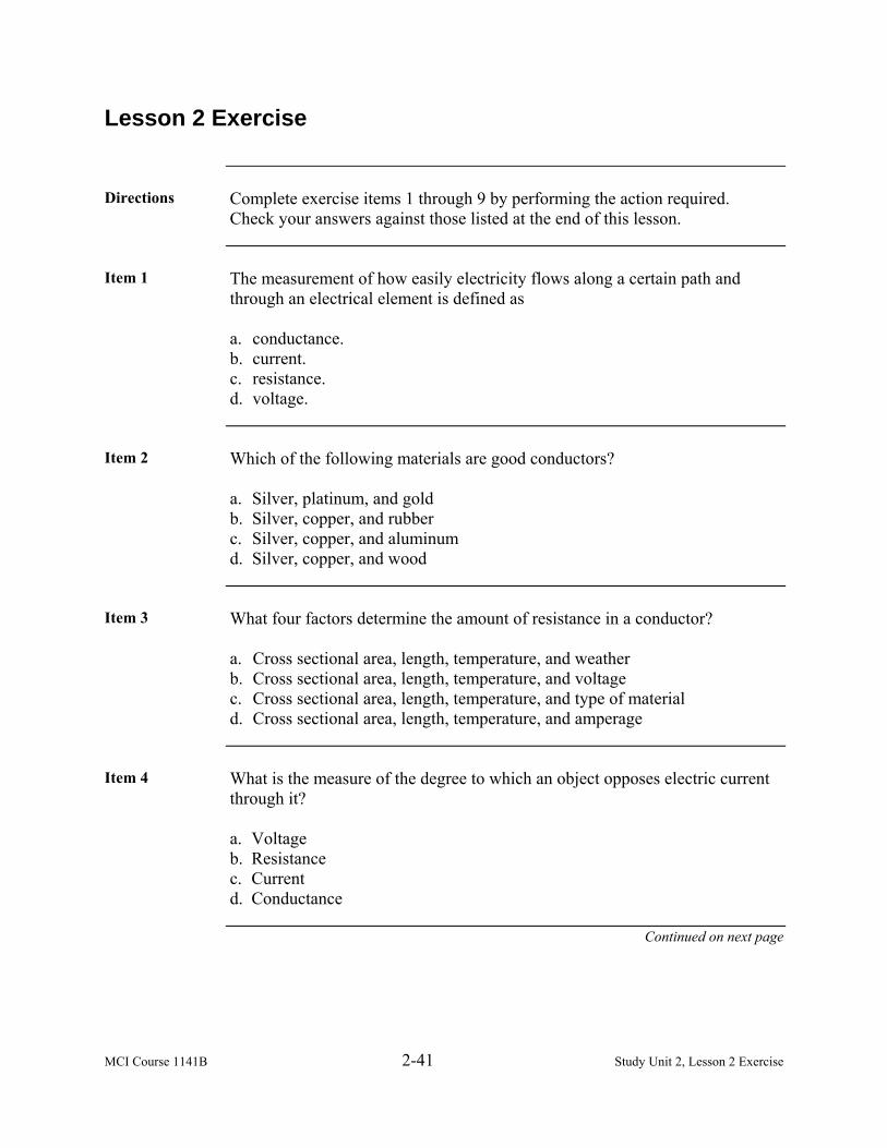
MCI Course 1141B 2-41 Study Unit 2, Lesson 2 Exercise
Lesson 2 Exercise
Directions Complete exercise items 1 through 9 by performing the action required.
Check your answers against those listed at the end of this lesson.
Item 1 The measurement of how easily electricity flows along a certain path and
through an electrical element is defined as a. conductance. b. current. c. resistance. d. voltage.
Item 2 Which of the following materials are good conductors?
a. Silver, platinum, and gold b. Silver, copper, and rubber c. Silver, copper, and aluminum d. Silver, copper, and wood
Item 3 What four factors determine the amount of resistance in a conductor?
a. Cross sectional area, length, temperature, and weather b. Cross sectional area, length, temperature, and voltage c. Cross sectional area, length, temperature, and type of material d. Cross sectional area, length, temperature, and amperage
Item 4 What is the measure of the degree to which an object opposes electric current
through it? a. Voltage b. Resistance c. Current d. Conductance
Continued on next page

MCI Course 1141B 2-42 Study Unit 2, Lesson 2 Exercise
Lesson 2 Exercise, Continued
Item 5 From the list below, which items would make good resistors?
a. Iron, nichrome, and silver b. Glass, rubber, and aluminum c. Glass, copper, and nylon d. Glass, nylon, and silver
Item 6 What is the resistance of an aluminum wire that has an ohms resistance of 17
per mil foot, 10400 area in circular mils, and a length of 100 feet? a. .001 ohms b. .016 ohms c. .16 ohms d. 16 ohms
Item 7 What chart assigns numbers from 0 to 44 for identifying their gauge and lists
resistance readings for wire that uses copper and aluminum? a. American Brown Wire Gauge Chart b. American Standard Gauge Chart c. American Standard Wire Gauge Chart d. American Wire Gauge Chart
Item 8 What are the types of stranded wire?
a. Bunch, concentric, and wire b. Bunch, concentric, and rope c. Bunch, concentric, and round d. Bunch, concentric, and coiled
Continued on next page
MCI Course 1141B 2-43 Study Unit 2, Lesson 2 Exercise
Lesson 2 Exercise, Continued
Item 9 The two methods used to strip wire from its protective sheathing are
_________ and pocketknife. a. combination tool b. hammer c. screwdriver d. pliers
Continued on next page

MCI Course 1141B 2-44 Study Unit 2, Lesson 2 Exercise
Lesson 2 Exercise, Continued
Answers The table below lists the answers to the exercise items. If you have questions
about these items, refer to the reference page.
Item Number Answer Reference 1 a 2-23 2 c 2-23 3 c 2-23 4 b 2-24 5 a 2-25 6 c 2-25 and 2-27 7 d 2-29 8 b 2-36 9 a 2-39

MCI Course 1141B 2-45 Study Unit 2, Lesson 3
LESSON 3
INTERNATIONAL ELECTRICITY
Introduction
Scope As a Marine electrician, you may have to work with different types of
electrical voltages, connectors, and receptacles used throughout the world. In this lesson, we will learn the types and identify the different styles of material conductors.
Learning Objectives
Upon completion of this lesson, you will be able to • Identify the importance of a third pin on the outlet. • Identify the different types of electrical connectors. • Identify the steps to connect wires to screw terminals. • Identify the steps to connect wire to switches receptacles with push-in
fittings.
In This Lesson This lesson contains the following topics:
Topic See Page Introduction 2-45 World Electricity 2-46 World Electrical Connectors 2-47 Types 2-48 Connect Electrical Connectors 2-57 International Wire Gauge 2-59 Lesson 3 Exercise 2-61

MCI Course 1141B 2-46 Study Unit 2, Lesson 3
World Electricity
History Ever since Nicola Tesla invented the three-phase alternating current of
electrical generation and distribution, the world has made many changes to the voltage and frequency that is used in alternating-current transmission. Nicola Tesla made many careful calculations and measurements and found out that 60 hertz was the better frequency than 50 hertz when it came to generating and distributing alternating current. At the same point in history, Thomas Edison worked with direct current voltage and systems, and stated as a safety factor that 110 volts of direct current was safer than Nicola Tesla’s 240 volts of alternating current. This began the manufacturing warfare of electrical systems throughout the world.
Manufacturing When the first European alternating-current generating facility was built, its
engineers decided to fix the frequency at 50 hertz, because the number 60 did not fit the metric standard unit sequence. At this time, the German company called (AEG) had a virtual monopoly and their standard of 240 volts at 50-hertz alternating current spread throughout the European continent. It was not until after World War II that England became standard to the European version of 240 volts at 50-hertz alternating current.
Frequency Difference
Fifty hertz is less effective in generation and is 15 percent less effective in transmission. It requires its windings and magnetic core materials in transformers to be 30 percent larger than those produced in our hemisphere. It has been proven that electric motors are much less efficient at lower frequency and must be made more robust to handle the electrical losses and extra heat that is generated from the lower frequency.
Voltage Europe and most other countries in the world use a voltage which is twice that
of the United States which is between 220 and 240 volts alternating current, whereas Japan and the United States is between 100 and 120 volts alternating current. Appendix A depicts over 214 countries around the world with their voltages and frequencies that are used inside their country. Over 175 countries use 220 to 240 volts compared to 39 countries that use 100 to 120 volts.

MCI Course 1141B 2-47 Study Unit 2, Lesson 3
World Electrical Connectors
Overview When electricity was first introduced into the domestic environment, it was
primarily used for lighting. However, as it became a more viable option for heating and the development of appliances, a means of connection to the supply was required. In the 1920s, the two-prong plug was invented. As the need for safer installations grew, three-pin outlets were developed. The third pin on the outlet is an earth pin, which was effectively connected to the earth. The idea behind this concept was that in the event of a short circuit to earth, a fuse would blow, which disconnects the electrical supply.
Types With voltages and frequencies, many countries preferred to develop their own
plug instead of adopting a standard one. We have more than 13 different styles of plugs and wall outlets used throughout the world today. Moreover, the plugs and sockets are very rarely compatible, which makes it often necessary to replace the plug when you purchase an appliance abroad. As a Marine electrician, we want to ensure that you will not make a mistake of using infrastructure that is not capable of supporting you and your equipment. Refer to Appendix A for a more detailed description of the different types of electrical connectors, voltages, and frequencies.

MCI Course 1141B 2-48 Study Unit 2, Lesson 3
Types
Type A Type A (shown below) is a class II ungrounded plug with two flat parallel
prongs. It is standard in most of North and Central America. At first glance, the Japanese plug and socket seem to be identical to this standard. However, the Japanese plug has two identical flat prongs, whereas the U.S. plug has one prong, which is slightly larger. Therefore, it is no problem to use Japanese plugs in the United States, but the opposite does not work often. Furthermore, Japanese standard wire sizes and the resulting current ratings are different from those used in American.
If you take apart the type A socket and look at the contact wipers that the prongs slide into, you would find that in some cases they have bumps on them. These bumps fit into the holes so that the outlet can grip the plug’s prongs more firmly. This prevents the plug from slipping out of the socket due to the weight of the plug and cord. It also improves the contact between the plug and the outlet. Some sockets, however, do not have those bumps but just two spring-action blades that grip the sides of the plug pin, in which case the holes are not necessary.
Continued on next page

MCI Course 1141B 2-49 Study Unit 2, Lesson 3
Types, Continued
Type B Type B (shown below) is a class I plug with two flat parallel prongs and a
grounding pin (American standard NEMA 5-15/Canadian standard CS22.2, n°42). This plug is rated at 15 amps and although standard in Japan, it is less frequently used than in North America. Consequently, most appliances sold in Japan use a class II ungrounded plug. As is the case with the type A standard, the Japanese type B plugs and sockets are slightly different from their American counterparts.
An ungrounded version of the type B plug is commonly used in Central America and parts of South America. This plug is common for equipment users to cut off the grounding pin that the plug can be mated with a two-pole ungrounded socket.
Type C Type C (shown on next page) is a two-wire plug that is ungrounded and has
two round prongs. It is popularly known as the europlug, which is described in CEE 7/16. This is probably the single most widely used international plug. It will mate with any socket that accepts 4.0 to 4.8mm round contacts on 19mm centres. The plug is generally limited for use in class II applications that require 2.5 amps or less, which is unpolarized. The type C is used in all countries of Europe except the United Kingdom and Ireland. It is also used in various parts of the developing world.
Continued on next page

MCI Course 1141B 2-50 Study Unit 2, Lesson 3
Types, Continued
Type C Sockets Type C plugs are very commonly used which is not the case for type C
sockets. This kind of socket is the older and ungrounded variant of socket types E, F, J, K and L. Nowadays, most countries demand grounded sockets to be installed in new buildings. Since type C sockets are ungrounded, they are currently being phased out in many countries and replaced by type E, F, J, K or L (depending on the country). A type C plug fits perfectly into a type E, F, J, K or L socket. The type C plug and connector is used in all countries of Europe except the United Kingdom, Ireland, Cyprus, and Malta.
Type D India has standardized on a plug, which was originally defined in British
Standard 546 (the standard in Great Britain before 1962). Type D plug (shown below) has three large round pins in a triangular pattern, which is rated at 5 amps. Type M, which has larger pins and is rated at 15 amps, is used alongside type D for larger appliances in India, Sri Lanka, Nepal, and Namibia. Some sockets can take both type M and type D plugs.
Although type D is now almost exclusively used in India, Sri Lanka, Nepal, and Namibia, it can still occasionally be found in hotels and theatres in the United Kingdom and Ireland. Note that tourists should not attempt to connect anything to a BS546 round-pin outlet found in the United Kingdom or Ireland, as it is likely to be on a circuit that has a special purpose, e.g. for providing direct current (DC) or for plugging in lamps that are controlled by a light switch or a dimmer.
Continued on next page

MCI Course 1141B 2-51 Study Unit 2, Lesson 3
Types, Continued
Type E The type E plug and connector (shown below) is primarily used in France,
Belgium, Poland, Slovakia, the Czech Republic, Tunisia, and Morocco. France, Belgium and some other countries have standardized on a socket, which is different from the CEE 7/4 socket (type F) that is standard in Germany and other continental European countries. The reason for incompatibility is that grounding in the type E socket is accomplished with a round male pin permanently mounted in the socket. The plug itself is similar to type C except that it is round and has the addition of a female contact to accept the grounding pin in the socket. To bridge the differences between sockets E and F, the CEE 7/7 plug was developed, which has grounding clips on both sides to mate with the type F socket, and a female contact to accept the grounding pin of the type E socket. The original type E plug, which does not have grounding clips, is no longer used, although very rarely it can still be found on some older appliances. Note: The CEE 7/7 plug is polarized when used with a type E outlet. The
plug is rated at 16 amps. Above that, equipment must either be wired permanently to the mains, or connected via another higher power connector such as the IEC 309 system. A type C plug fits perfectly into a type E socket.
Continued on next page

MCI Course 1141B 2-52 Study Unit 2, Lesson 3
Types, Continued
Type F Type F (shown below) is used in Germany, Austria, the Netherlands, Sweden,
Norway, Finland, Portugal, Spain, and Eastern Europe. Known as CEE 7/4 and commonly called “Schuko plug”, it is similar to type C except that it is round and has the addition of two grounding clips on the side of the plug. The type F has two 4.8 mm round contacts on 19mm centres. Because the CEE 7/4 plug can be inserted in either direction into the receptacle, the Schuko connection system is unpolarized (i.e., line and neutral are connected at random). In addition, it is used in applications up to 16 amps. Equipment must either be wired permanently to the mains or connected via another higher power connector such as the IEC 309 system. To bridge the differences between sockets E and F, the CEE 7/7 plug was developed. Type F plug has grounding clips on both sides to mate with the type F socket and a female contact to accept the grounding pin of the type E socket. The original type F plug, which does not have this female contact, is still available at the DIY shops, but only in a new version. A type C plug fits perfectly into a type F socket.
Continued on next page

MCI Course 1141B 2-53 Study Unit 2, Lesson 3
Types, Continued
Type G Type G (shown below) is used mainly in the United Kingdom, Ireland,
Cyprus, Malta, Malaysia, Singapore, and Hong Kong. This plug has three rectangular prongs that form a triangle. British Standard BS 1363 requires use of a three-wire grounded and fused plug for all connections to the power mains (including class II, two-wire appliances). British power outlets incorporate shutters online and neutral contacts to prevent someone from pushing a foreign object into the socket.
The British domestic electrical system uses a ring circuit in the building, which is rated for 32 amps (6 amps for lighting circuits, which are usually spurs). Moreover, there is also a fusing in the plug; a cartridge fuse, usually of 3 amps for small appliances like radios and 13 amps for heavy-duty appliances such as heaters. Almost everywhere else in the world, a spur main system is used. In this system, each wall socket or group of sockets has a fuse at the main switchboard whereas the plug has none. If you take foreign appliances to the United Kingdom, use an adaptor, but technically it must incorporate the correct value fuse. Most would have 13 amps, which is too big for the computer. BS 1363 was published in 1962 and gradually replaced the earlier standard plugs and sockets (type D) (BS 546).
Continued on next page

MCI Course 1141B 2-54 Study Unit 2, Lesson 3
Types, Continued
Type H Type H (shown below), as defined in SI 32, is unique to Israel. This plug has
two flat prongs like the type B plug, but they form a V-shape rather than being parallel like B plugs. Type H plugs has a grounding pin, which is rated at 16 amps. Type H sockets are so shaped as to accommodate type C plugs as well. The slots for the non-grounded prongs have slots in the middle specifically to allow type C prongs to fit in.
Type I Type I connectors (shown below) are mainly used in Australia, New Zealand,
Papua New Guinea and Argentina. This plug has a grounding pin and two flat prongs forming a V-shape. There is an ungrounded version of this plug as well, with only two flat V-shaped prongs. Although the above plug looks similar to the one used in Israel (type H), both plugs are not compatible. Australia’s standard plug/socket system is described in SAA document AS 3112 and is used in applications up to 10 amps. A plug/socket configuration with rating at 15 amps (ground pin is wider: 8 mm instead of 6.35 mm) is also available. A standard 10-amp plug will fit into a 15-amp outlet, but a 15-amp plug only fits this special 15-amp socket. In addition, there is a 20-amp plug whose prongs are still wider. A lower-amperage plug will always fit into a higher-amperage outlet, but not vice versa. Although there are slight differences, the Australian plug mates with the socket used in the People’s Republic of China (mainland China).
Continued on next page

MCI Course 1141B 2-55 Study Unit 2, Lesson 3
Types, Continued
Type J Switzerland has its own standard, which is described in SEC 1011. Type J
(shown below) is similar to type C, except that it has the addition of a grounding pin. This connector system is rated for use in applications up to 10 amps. Above 10 amps, equipment must be either wired permanently to the electrical supply system with appropriate branch circuit protection or connected to the mains with an appropriate high power industrial connector.
Type K Type K connectors (shown below) is used almost exclusively in Denmark and
Greenland. The Danish standard is described in Afsnit 107-2-D1. The plug is similar to type F except that it has a grounding pin instead of grounding clips. The Danish socket will also accept either the CEE 7/4 or CEE 7/7 plugs; however, there is no grounding connection with these plugs because a male ground pin is required on the plug. The correct plug must be used in Denmark for safety reasons. A variation of this plug intended for use only on surge protected computer circuits has been introduced. The current rating on both plugs is 10 amps. A type C plug fits perfectly into a type K socket.
Continued on next page
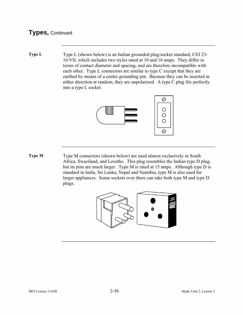
MCI Course 1141B 2-56 Study Unit 2, Lesson 3
Types, Continued
Type L Type L (shown below) is an Italian grounded plug/socket standard, CEI 23-
16/VII, which includes two styles rated at 10 and 16 amps. They differ in terms of contact diameter and spacing, and are therefore incompatible with each other. Type L connectors are similar to type C except that they are earthed by means of a centre grounding pin. Because they can be inserted in either direction at random, they are unpolarized. A type C plug fits perfectly into a type L socket.
Type M Type M connectors (shown below) are used almost exclusively in South
Africa, Swaziland, and Lesotho. This plug resembles the Indian type D plug, but its pins are much larger. Type M is rated at 15 amps. Although type D is standard in India, Sri Lanka, Nepal and Namibia, type M is also used for larger appliances. Some sockets over there can take both type M and type D plugs.

MCI Course 1141B 2-57 Study Unit 2, Lesson 3
Connect Electrical Connectors
Application Now that we have a basic understanding of the different voltages and types of
connectors, let us cover the steps to connect the electrical connectors to electrical wire. Note: Follow the steps below using basic Romex cable for application used
with electrical wire to connect wires to screw terminals.
Step Action 1 Perform lock out and tag out procedures to ensure that all
electricity is off to any and electrical wire and component. 2 Using the installed wire or replacing it with new wire, strip the
wire approximately ¾” of insulation from each wire by either using a combination tool or a knife. If using a knife, strip the wire by stripping the wire away from you. If you are using the combination tool, choose the stripper opening that matches the gauge of the wire, then clamp wire in tool and pull the wire firmly to remove the plastic insulation.
3 Form a C-shaped loop in the end of each wire by using needle nose pliers. The wires should have no scratches or nicks.
4 If using Romex cable, take the black wires and attach them to the gold plated screws of the connector and the white wires will be attached to the silver screws of the connector.
5 Ensure that the curved ends of the wire are looped around the screws in the same direction that you will tighten the screws.
6 Tighten the screws firmly, ensuring that the insulation does not touch the head of the screw.
Continued on next page

MCI Course 1141B 2-58 Study Unit 2, Lesson 3
Connect Electrical Connectors, Continued
Push-In Fittings
The table below shows how to connect wires to switches receptacles with push-in fittings.
Step Action
1 Perform lock out and tag out procedures to ensure that all electricity is off to any and electrical wire and component.
2 Mark the amount of insulation to be stripped from each wire using the strip gauge on the back of the switch or receptacle.
3 Strip the wires the length that has been measured with either a knife or a combination tool.
4 Insert the bare copper wires firmly into the push-in fittings on the back of the switch or receptacle. Note: Never use push-in fittings with aluminum wires. When
inserted, wires should have no bare copper exposed. 5 Remove the wire by using a nail, screwdriver, or scratch awl to
push in the fitting in the release opening next to or above the wire. The wire should pull out easily. Note: Although push-in fittings are convenient and found
throughout the world, most experts believe screw terminal connections are more dependable.

MCI Course 1141B 2-59 Study Unit 2, Lesson 3
International Wire Gauge
Wire Size Standards
Conductor size is measures by two different standards; the old imperial size used in North America is American Wire Gauge (AWG) systems. This standard has a set value number for each size of wire used in industry. In most cases only an even number is used, a #4 wire is typical for starter cable, while a #16 wire is common for lighting circuits. AWG standards: as the size number increases, the wire diameter decreases. The metric standard is becoming more common today. It calculates the cross sectional conductor area in square millimeters. For example, a 0.8 mm2 wire may be used for a taillight, while a 13.0 mm2 wire would be used for a starter cable. Metric standards: as the size number increases, the wire diameter increases. The table below shows the metric to AWG Conversion Table.
Metric Size mm2
AWG Size
0.5 20 0.8 18 1.0 16 2.0 14 3.0 12 5.0 10 8.0 8 13.0 6 19.0 4 32.0 2 52.0 0

MCI Course 1141B 2-60 Study Unit 2, Lesson 3
(This page intentionally left blank.)

MCI Course 1141B 2-61 Study Unit 2, Lesson 3 Exercise
Lesson 3 Exercise
Directions Complete exercise items 1 through 13 by performing the action required.
Check your answers against those listed at the end of this lesson.
Item 1 The importance of a third pin on the outlet is to prevent
a. the fuse from blowing. b. electrocution. c. burning your hands. d. death.
Item 2 Through Item 8
Matching: For items 2 through 8, match the electrical connector in column 1 with its description in column 2.
Column 1 Electrical Connector
Column 2 Description
___ 2. Type A ___ 3. Type B ___ 4. Type C ___ 5. Type D ___ 6. Type E ___ 7. Type F ___ 8. Type G
a. Three-rectangular prongs that
form a triangle b. Class II ungrounded plug with
two flat parallel prongs c. Round and has two grounding
clips on the side of the plug d. Class I plug with two flat parallel
prongs e. Two-wire plug that is
ungrounded and two round prongs
f. Three large round pins in a triangular pattern
g. Round male pin permanently mounted in the socket
Continued on next page

MCI Course 1141B 2-62 Study Unit 2, Lesson 3 Exercise
Lesson 3 Exercise, Continued
Item 9 Which connector shown below is used in Australia, New Zealand, Papua New
Guinea, and Argentina?
a. Type B b. Type C c. Type G d. Type I
Item 10 Which connector shown below is unique in Israel, has two flat prongs, and
forms a V-shape?
a. Type A b. Type H c. Type G d. Type I
Continued on next page

MCI Course 1141B 2-63 Study Unit 2, Lesson 3 Exercise
Lesson 3 Exercise, Continued
Item 11 Which connector shown below is an Italian grounded plug/socket standard,
CEI 23-16/VII?
a. Type A b. Type B c. Type L d. Type D
Item 12 When connecting the electrical connectors to electrical wire, use the installed
wire and strip the wire approximately ______ of insulation from each wire by either using a combination tool or a knife. a. 3/4” b. 1/2” c. 1” d. 1.5”
Item 13 When connecting the wires to switch receptacles with push-in fittings, insert
the bare copper wires firmly into the push-in fittings on the _______ of the switch or receptacle. a. front b. side c. top d. back
Continued on next page

MCI Course 1141B 2-64 Study Unit 2, Lesson 3 Exercise
Lesson 3 Exercise, Continued
Answers The table below lists the answers to the exercise items. If you have questions
about these items, refer to the reference page.
Item Number Answer Reference 1 a 2-47 2 b 2-48 3 d 2-49 4 e 2-49 5 f 2-50 6 g 2-51 7 c 2-52 8 a 2-53 9 d 2-54 10 b 2-54 11 c 2-56 12 a 2-57 13 d 2-58
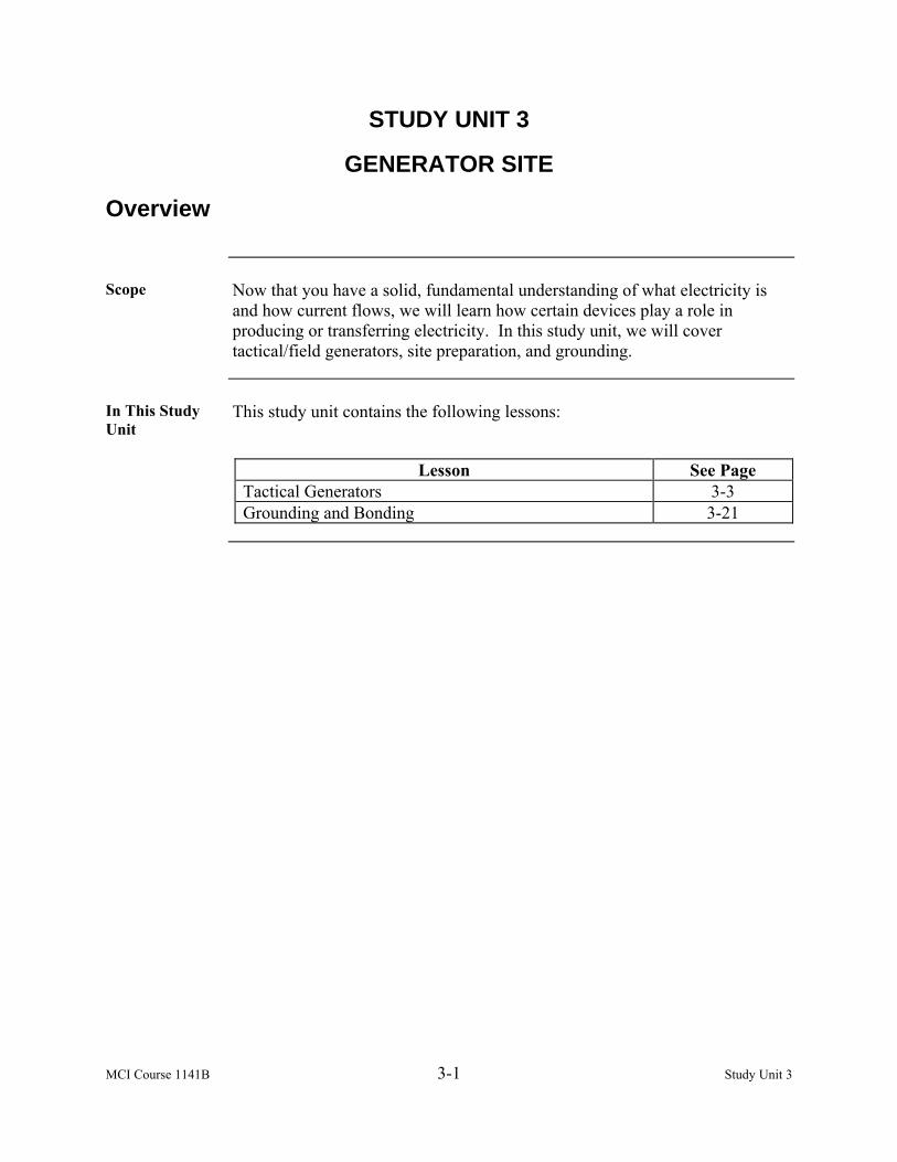
MCI Course 1141B 3-1 Study Unit 3
STUDY UNIT 3
GENERATOR SITE
Overview
Scope Now that you have a solid, fundamental understanding of what electricity is
and how current flows, we will learn how certain devices play a role in producing or transferring electricity. In this study unit, we will cover tactical/field generators, site preparation, and grounding.
In This Study Unit
This study unit contains the following lessons:
Lesson See Page
Tactical Generators 3-3 Grounding and Bonding 3-21

MCI Course 1141B 3-2 Study Unit 3
(This page intentionally left blank.)

MCI Course 1141B 3-3 Study Unit 3, Lesson 1
LESSON 1
TACTICAL GENERATORS
Introduction
Scope The demand for electricity in military field operations is extensive and varied.
A generator is a device that converts kinetic energy to electrical energy, generally using electromagnetic induction by creating relative motion between a magnetic field and a conductor. A power station (also referred to as a generating station or power plant) is an industrial facility for the generation of electric power. Power plant is the most common term in the United States, while elsewhere power station and power plant are both widely used, power station prevailing in many commonwealth countries and especially in the United Kingdom. In this lesson, we will identify the types of generators used in the Marine Corps, how to choose the generator site, and identify environmental protection equipment.
Learning Objectives
Upon completion of this lesson, you will be able to • Identify the types of generators. • Identify tactical generator characteristics. • Identify the use of load cables. • Identify factors when choosing a site. • Identify refueling requirements. • Identify environmental protection equipment.
Continued on next page
MCI Course 1141B 3-4 Study Unit 3, Lesson 1
Introduction, Continued
In This Lesson This lesson contains the following topics:
Topic See Page Introduction 3-3 Turbines 3-5 Engines 3-6 Portable Generators 3-7 Site Preparation 3-12 Lesson 1 Exercise 3-17

MCI Course 1141B 3-5 Study Unit 3, Lesson 1
Turbines
Definition A turbine is a rotary engine that extracts energy from a fluid flow and uses it
to run a generator. The simplest turbines have one moving part, a rotor assembly, which is a shaft with blades attached. Moving fluid acts on the blades, or the blades react to the flow, so that they rotate and impart energy to the rotor. Early turbine examples are windmills and water wheels.
Theory of Operation
A working fluid contains potential energy (pressure head) and kinetic energy (velocity head). The fluid may be compressible or incompressible. The following are two types of turbines that may be used to create energy to produce electricity: • Impulse • Reaction
Impulse These turbines change the direction of flow of a high velocity fluid jet. The
resulting impulse spins the turbine and leaves the fluid flow with diminished kinetic energy. Impulse turbines do not require a pressure casement around the runner since the fluid jet is prepared by a nozzle prior to reaching turbine.
Reaction These turbines develop torque by reacting to the fluid’s pressure or weight.
The pressure of the fluid changes as it passes through the turbine rotor blades. A pressure casement is needed to contain the working fluid as it acts on the turbine stage(s) or the turbine must be fully immersed in the fluid flow (wind turbines). The casing contains and directs the working fluid, and for water turbines, maintains the suction imparted by the draft tube. Most steam turbines use this concept.
Steam Turbine A steam turbine is a mechanical device that extracts thermal energy from
pressurized steam and converts it into useful mechanical work. It has almost completely replaced the reciprocating piston steam engine, primarily because of its greater thermal efficiency and higher power-to-weight ratio. Also, because the turbine generates rotary motion, rather than requiring a linkage mechanism to convert reciprocating to rotary motion, it is particularly suited for use driving an electrical generator. About 86 percent of all electric generation in the world uses steam turbines.
MCI Course 1141B 3-6 Study Unit 3, Lesson 1
Engines
Definition An engine-generator is the combination of an electrical generator and an
engine (prime mover) mounted together to form a single piece of equipment. This combination is also called an engine-generator set or a gen-set. In many contexts, the engine is taken for granted and the combined unit is called a generator.
In addition to the engine and generator, engine-generators include a fuel tank, an engine speed regulator, a generator voltage regulator, cooling and exhaust systems, and in some cases, a lubrication system. Units larger than 1 kW rating have a battery and electric starter; very large units may start with compressed air. Standby power generating units often include an automatic starting system and a transfer switch to disconnect the load from the utility power source and connect it to the generator. The engine is the most mobile and capable of producing electricity in any type of environment. There are commercial grade units and tactical units that you should focus on.
Note: The engine generator requires classroom and practical application instruction time to apply, and be certified to run any of the tactical generator units. This lesson will not cover those instructions or information on how to operate any of the tactical generators, however it is designed to inform you of the characteristics that is crucial in determining which generator is required to perform the task or mission.
Performing operator checks and services must be performed according to the operator’s technical manual.

MCI Course 1141B 3-7 Study Unit 3, Lesson 1
Portable Generators
Characteristics As an electrician, you will be required to select the type of generator that
most closely meets the requirements of the task. The Marine Corps uses the following TQG series of generators: • TQG-803 • TQG-805 • TQG-806 • TQG-807A • TQG-831A
TQG-803 The TQG-803 is fully enclosed, self-contained skid-mounted, portable
generator. The generator set consists of a diesel engine, brushless generator, excitation system, speed governing system, fuel system, 24-volt DC starting system, and a control/fault system. The TQG-803 has an equivalent generator, TQG-813, that produces electricity at 400 hertz.
TQG-805 The TQG-805 is fully enclosed, self-contained skid-mounted, portable
generator. It is equipped with controls, instruments, and accessories necessary for operation as a single unit or in parallel with another unit of the same class and mode. The generator set consists of a diesel engine, brushless generator, excitation system, speed governing system, fuel system, 24-volt DC starting system, and a control/fault system. The TQG-805 has an equivalent generator, TQG-815, that produces electricity at 400 hertz.
TQG-806 The TQG-806 is fully enclosed, self-contained skid-mounted, portable
generator. It is equipped with controls, instruments, and accessories necessary for operation as a single unit or in parallel with another unit of the same class and mode. The generator set consists of a diesel engine, brushless generator, excitation system, speed governing system, fuel system, 24-volt DC starting system, and a control/fault system. The TQG-806 has an equivalent generator, TQG-816, that produces electricity at 400 hertz.
Continued on next page

MCI Course 1141B 3-8 Study Unit 3, Lesson 1
Portable Generators, Continued
TQG-807A The TQG-807A is fully enclosed, self-contained skid-mounted, portable
generator. It is equipped with controls, instruments, and accessories necessary for operation as a single unit or in parallel with another unit of the same class and mode. The generator set consists of a diesel engine, brushless generator, excitation system, speed governing system, fuel system, 24-volt DC starting system, and a control system, fault system, and Electronic Modular Control Panel (EMCP).
TQG-831A The TQG-831A is a self-contained, skid-mounted, portable generator that is
equipped with controls, instruments, and accessories necessary for operation. The generator set consists of a diesel engine, permanent magnetic AC generator, control box assembly, output/load panel, primary and auxiliary fuel systems, enclosure cooling and ventilation system, and a 24-volt DC battery. The TQG-831A is used with any equipment requiring a small source of AC power with a six-person lift.
Continued on next page

MCI Course 1141B 3-9 Study Unit 3, Lesson 1
Portable Generators, Continued
Description The table below shows a more detailed description of portable generators.
Generator Set TQG-803 TQG-805 TQG-806 Frequency 60 Hz 50/60 Hz 50/60 Hz Rating 10 kW 30 kW 60 kW AC Volt Output 120/208 &
120/240 120/208 &
240/416 120/208 &
240/416 KVA 12.5 37.5 75 Low Y & High Y N/A & N/A 104 & 52 208 & 104 Engine Speed 1800 RPM 1800 RPM 1800 RPM Fuel Tank Capacity 9 Gallons 23 Gallons 43 Gallons Fuel Per Hour 1.07 Gallons 2.43 Gallons 4.51 Gallons Oil Capacity 5.9 Quarts 15 Quarts 18 Quarts Coolant Capacity 8.2 Quarts 15.5 Quarts 20.5 Quarts Engine Manufacture Onan John Deere John Deere Engine Cylinders 4 4 6 Cubic Feet 41.5 88 103 Weight 1182 3006 4063 Dimensions (LxWxH) 62x32x37 79.7x35.7x55 87x35.7x59
Generator Set TQG-813 TQG-815 TQG-816 Frequency 400 Hz 400 Hz 400 Hz Rating 10 kW 30 kW 60 kW AC Volt Output 120/208 &
120/240 120/208 &
240/416 120/208 &
240/416 KVA 12.5 37.5 75 Low Y & High Y N/A & N/A 104 & 52 208 & 104 Engine Speed 2000 RPM 2000 RPM 2000 RPM Fuel Tank Capacity 9 Gallons 23 Gallons 43 Gallons Fuel Per Hour 1.00 Gallons 2.69 Gallons 4.69 Gallons Oil Capacity 5.9 Quarts 15 Quarts 18 Quarts Coolant Capacity 8.2 Quarts 15.5 Quarts 20.5 Quarts Engine Manufacture Onan John Deere John Deere Engine Cylinders 4 4 6 Cubic Feet 41.5 88 103 Weight 1220 3015 4153 Dimensions (LxWxH) 62x32x37 79.7x35.7x55 87x35.7x59
Continued on next page

MCI Course 1141B 3-10 Study Unit 3, Lesson 1
Portable Generators, Continued
Description, continued
Generator Set TQG-807A TQG-805B/ Digital TQG-806B/ Digital
Frequency 60 Hz 60 Hz 60 Hz Rating 100 kW 30 kW 60 kW AC Volt Output 120/208 & 240/416 120/208 & 240/416 120/208 &
240/416 KVA 37.5 75 Low Y & High Y 104 & 52 208 & 104 Engine Speed 1800 RPM 1800 RPM 1800 RPM Fuel Tank Capacity 66 Gallons 23 Gallons 43 Gallons Fuel Per Hour 7.85 Gallons 2.60 Gallons 4.7 Gallons Oil Capacity 30 Quarts 15 Quarts 18 Quarts Coolant Capacity 38 Quarts 15.5 Quarts 20.5 Quarts Engine Manufacture Caterpillar John Deere John Deere Engine Cylinders 6 4 6 Cubic Feet 156 88 103 Weight 6100 3040 4200 Dimensions (LxWxH) 106x40x65 79.7x35.7x55 87x35.7x59
Generator Set TQG-831A TQG-815B/
Digital TQG-816B/
Digital Frequency 60 Hz 400 Hz 400 Hz Rating 3 kW 30 kW 60 kW AC Volt Output 120/240 120/208 &
240/416 120/208 &
240/416 KVA 37.5 75 Low Y & High Y N/A & N/A 104 & 52 208 & 104 Engine Speed 3600 RPM 2000 RPM 2000 RPM Fuel Tank Capacity 4 Gallons 23 Gallons 43 Gallons Fuel Per Hour .5 Gallons 2.69 Gallons 4.90 Gallons Oil Capacity 1.2 Quarts 15 Quarts 18 Quarts Coolant Capacity Air Cooled 15.5 Quarts 20.5 Quarts Engine Manufacture Yanmar John Deere John Deere Engine Cylinders 1 4 6 Cubic Feet 15 88 103 Weight 334 3060 4240 Dimensions (LxWxH) 35x28x27 79.7x35.7x55 87x35.7x59
Continued on next page

MCI Course 1141B 3-11 Study Unit 3, Lesson 1
Portable Generators, Continued
Installing Load Cables
As an electrician, understand that connecting the load cables to a generator is an important process to provide electricity for a mission. Never attempt to connect or disconnect load cables while the generator set is running. Failure to comply may result in severe personal injury or death. Follow the steps below to install load cables for each generator.
Step Action 1 Ensure that the generator set is turned off and the cable is not
connected to a service panel or other distribution equipment at the other end.
2 Open output load terminal door that is located by the canvas sleeve of the generator set.
3 Determine and select the required output terminals that you are going to use to provide electricity. Note: To balance the load requirements amongst the terminals is
important, which will be covered in the next study unit. 4 Using the terminal nut wrench that is mounted to the inside of the
load terminal area, loosen the terminals nuts by turning them counterclockwise. Ensure that there is no debris on the terminals. Clean them with some preventive cleaner if they are dirty or corroded.
5 Insert the ends of the load cables through the load cable entrance box and sleeve.
6 Then insert into the proper slots of the load terminal studs. We will discuss color coding sequence of cables in the next study unit.
7 Ensure the cable ends are inserted into the slots and there are no excessive amounts over-extending through the terminal. Tighten the load terminal nuts clockwise down on the inserted cable until you have a tight connection. Be careful not to over tighten the load terminal nuts on the terminal studs.

MCI Course 1141B 3-12 Study Unit 3, Lesson 1
Site Preparation
Factors When preparing to use generators to provide electricity, you will choose a site
that will ensure the performance, safety and security of the equipment has been taken into consideration. The following factors are considered when selecting a site to generate electricity: • Performance • Terrain • Safety • Environment • Security
Performance The most important factor to consider when selecting a generator site should
be performance. A site should be selected where the largest demand loads are going to be located. This will aid in • Reducing the size and amount of wire distribution systems needed • Minimizing the line of voltage loss • Providing voltage control at the demand end of the line
Terrain The terrain is the second important factor when selecting a generator site.
When identifying the terrain in which you will be conducting your mission, consider the following aspects: • Type of terrain and soil conditions • Stability of the ground to support the equipment
Terrain and Soil Conditions
The soil conditions are important to the selection of the generator site. When it comes to grounding, the soil conditions may affect the performance of the generator. Grounding will be covered in the next lesson. The type of soil is also crucial in providing good drainage from the elements of weather. You do not want to establish a generator site in low-lying areas or an area that is susceptible to flash floods. Consider the type of equipment that will be used to support in establishing your generator site. Also, consider cranes, forklifts, and prime movers when selecting the site by taking into consideration their capabilities and limitations with regard to site locations.
Continued on next page

MCI Course 1141B 3-13 Study Unit 3, Lesson 1
Site Preparation, Continued
Stability The soil should also be stable. Level ground is always the best to work with
in this aspect. If the generator is to be skid-mounted for operation, ensure that you have planks, timbers, dunnage, logs, or ammunition boxes to prevent the skids or frame from sinking into the earth, especially if it becomes soft. For a generator to run properly, make sure it is level. Never tilt a generator set more than 15 degrees in any direction as this may cause damage during operation to the engine. If the generator is placed onto a trailer, ensure that the trailer is capable of adjustment to ensure the correct leveling.
Safety When using multiple generators, ensure there is adequate spacing between
each generator for the safety of personnel to conduct maintenance checks and services. This will provide accessibility in the event that a generator must be replaced. Warning signs and hazardous material signs should also be posted around the generator site. Note: Signs should be spelled in English and also in the host country’s
language to ensure there are no casualties.
Refueling Requirements
Another aspect to the overall performance of the generator is the ability to provide sustainability over long periods, essentially, refueling operations. Without fuel, you cannot produce electricity. Your generator site should be related to roads that are improved to handle all aspects of weather conditions. Unimproved roads may not allow refueling operations to be conducted during inclement weather. Most generator sets have an auxiliary fuel line used from a secondary fuel source. A secondary fuel source may be an additional 55- gallon fuel drum. Whatever the secondary fuel source may be, that fuel source cannot be more than 25 feet from the generator, which is the length of the auxiliary fuel line used from the secondary fuel source to the generator. When conducting refueling operations, you should consult the Operator’s Technical Manual for the type of fuel required. Most tactical generators that are used in the United States Marine Corps run on diesel (DF-2) or JP-8, which is mandated by Department of Defense.
Continued on next page
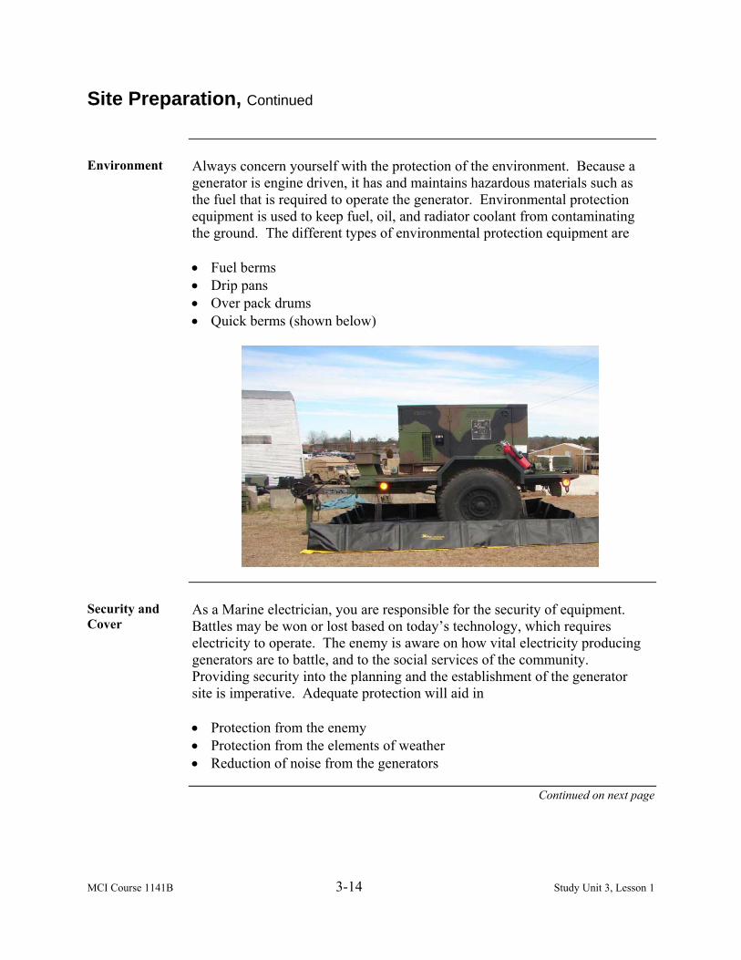
MCI Course 1141B 3-14 Study Unit 3, Lesson 1
Site Preparation, Continued
Environment Always concern yourself with the protection of the environment. Because a
generator is engine driven, it has and maintains hazardous materials such as the fuel that is required to operate the generator. Environmental protection equipment is used to keep fuel, oil, and radiator coolant from contaminating the ground. The different types of environmental protection equipment are • Fuel berms • Drip pans • Over pack drums • Quick berms (shown below)
Security and Cover
As a Marine electrician, you are responsible for the security of equipment. Battles may be won or lost based on today’s technology, which requires electricity to operate. The enemy is aware on how vital electricity producing generators are to battle, and to the social services of the community. Providing security into the planning and the establishment of the generator site is imperative. Adequate protection will aid in • Protection from the enemy • Protection from the elements of weather • Reduction of noise from the generators
Continued on next page

MCI Course 1141B 3-15 Study Unit 3, Lesson 1
Site Preparation, Continued
Additional Information
There is no standard way to provide for the security of the site. You must be creative and resourceful when creating the security for the generator site. The following are additional ways to aid in the security of the generator site: • Use natural surroundings as best as possible. • Build a revetment out of sandbags to enclose the generator site. • Use storage containers in the use of security. Solid walls from a container
will greatly prevent enemy fire on the generator and will also reduce the noise from the generator.
• Use portable jersey barriers that could be filled with water or sand.
Camouflage and Concealment
Camouflage and concealment is the protection from enemy observation. Camouflage blends in the natural surroundings and prevents the enemy from observing us. Also, it alters the generator site’s appearance so that it becomes part of the background. Arranging or applying camouflage material on, over, and around the target reduces its contrast with the background.

MCI Course 1141B 3-16 Study Unit 3, Lesson 1
(This page intentionally left blank.)

MCI Course 1141B 3-17 Study Unit 3, Lesson 1 Exercise
Lesson 1 Exercise
Directions Complete exercise items 1 through 10 by performing the action required.
Check your answers against those listed at the end of this lesson.
Item 1 A(n) ________ generator has a fuel tank, an engine speed regulator, a
generator voltage regulator, cooling and exhaust systems, and a lubrication system. a. engine b. turbine c. automatic d. nuclear
Items 2 Through 6
Matching: For items 2 through 6, match the generator in column 1 with its characteristics in column 2.
Column 1 Generator
Column 2 Characteristics
___ 2. TQG-803 ___ 3. TQG-805 ___ 4. TQG-806 ___ 5. TQG-807A ___ 6. TQG-831A
a. 100 kW, 50/60 Hz b. 30 kW, 50/60 Hz c. 10 kW, 60 Hz d. 3 kW, 60 Hz e. 60 kW, 50/60 Hz
Item 7 Where do you insert the ends of the load cables?
a. Load cable entrance box and sleeve b. In the slots c. Directly to the generator d. Terminal door
Continued on next page

MCI Course 1141B 3-18 Study Unit 3, Lesson 1 Exercise
Lesson 1 Exercise, Continued
Item 8 Which of the following is the most important factor when selecting a
generator site? a. Performance b. Terrain c. Safety d. Security
Item 9 Which requirement contributes to the overall performance of the generator by
providing sustainability over long periods of time? a. Terrain b. Refueling c. Environment d. Safety
Item 10 Environmental protection equipment is used to keep fuel, oil, and radiator
coolant from contaminating the ground. The different types include fuel berms, drip pans, __________, and over pack drums. a. fuel pans b. quick berms c. plates d. caps
Continued on next page

MCI Course 1141B 3-19 Study Unit 3, Lesson 1 Exercise
Lesson 1 Exercise, Continued
Answers The table below lists the answers to the exercise items. If you have any
questions about these items, refer to the reference page.
Item Number Answer Reference 1 a 3-6 2 c 3-7 3 b 3-7 4 e 3-7 5 a 3-8 6 d 3-8 7 a 3-11 8 a 3-12 9 b 3-13 10 b 3-14

MCI Course 1141B 3-20 Study Unit 3, Lesson 1 Exercise
(This page intentionally left blank.)
MCI Course 1141B 3-21 Study Unit 3, Lesson 2
LESSON 2
GROUNDING AND BONDING
Introduction
Scope To ensure that all generator and electrical distribution systems are properly
grounded, we will know the difference between grounding and bonding, how to install a tactical/field grounding system for electrical producing and distribution systems, improve soil conditions, and improve grounding capabilities.
Learning Objectives
Upon completion of this lesson, you will be able to • Define grounding.
• Define bonding.
• Identify grounding equipment.
• Identify the methods to install a ground rod.
• Identify soil conditions.
In This Lesson This lesson contains the following topics:
Topic See Page Introduction 3-21 Grounding 3-22 Bonding 3-24 Grounding Equipment 3-25 Ground Testing 3-30 Soil Conditions 3-33 Lesson 2 Exercise 3-35
MCI Course 1141B 3-22 Study Unit 3, Lesson 2
Grounding
Definition In electrical engineering, the term ground or earth has several meanings
depending on the specific application areas. Grounding is the reference point in an electrical circuit from which other voltages are measured, a common return path for electric current (earth return or ground return) or a direct physical connection to the Earth. The use of the term ground (or earth) is so common in electrical and electronics applications that circuits in vehicles such as ships, aircraft, and spacecraft spoken as having a “ground” connection without any actual connection to the Earth.
Purpose Grounding is required for electrical and electronic equipment. Most
equipment service manuals direct that the equipment be grounded before power is applied and the equipment placed in operation. All safety directives require electrical equipment to be grounded, and specify the methods required to be used. The most important aspects for grounding are • Safety • Equipment performance
Safety All electrical equipment, either producing or distributing, are compatible to
conditions that would make it unsafe and hazardous to users of the equipment. Proper grounding is vital in protecting personnel from injury or death. Improper wiring, moisture intrusion, equipment failure, or lightning can cause electrical faults subjecting personnel to electrical shock hazards. In accordance with the National Electric Code (Article 250.4), metal parts of an electrical installation are grounded to the earth to reduce voltage on the metal parts from lightning to prevent fires from a surface arc within the building or structure.
Equipment Performance
Grounding of power systems and equipment is a subject of major impact on system performance and the integrity of its equipment. Proper grounding design and installation are required to eliminate voltage differences between generators, power distribution systems, electrical equipment, and their components. To require all electrical circuits within an electrical system to maintain proper voltage relationships between those circuits will reduce any unwanted current flow and static buildup by allowing the ground to dissipate such unwanted flow. For proper performance of most electrical equipment, an established resistance reading of less than 10 ohms is required.
Continued on next page
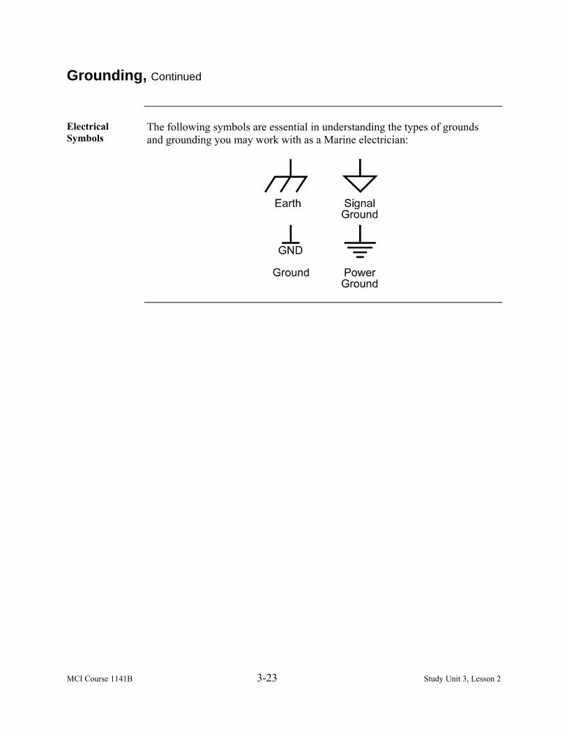
MCI Course 1141B 3-23 Study Unit 3, Lesson 2
Grounding, Continued
Electrical Symbols
The following symbols are essential in understanding the types of grounds and grounding you may work with as a Marine electrician:
MCI Course 1141B 3-24 Study Unit 3, Lesson 2
Bonding
Description A Marine electrician should understand that there is a significant difference
between grounding and bonding. Bonding is when a building or any other structure is served with electricity that is normal for safety reasons to connect all metal objects such as pipes, together to the mains of the earth to form an equipotential zone.
Example An example would be a swimming pool made of concrete and rebar steel, and
or fountains. For these pools and fountains, any conductor (meaning any metal that is not the wire conductor itself) over a certain size must be bonded to assure that all conductors are equipotential and do not provide a hazardous conductive path. When buried in the ground and having a small leak, a pool can be a better ground than the electric panel ground. When all the conducting elements are bonded properly, it is near impossible that the electric current will find a path through a swimmer. For additional information on bonding, refer to The National Electric Code in Article 250.118.

MCI Course 1141B 3-25 Study Unit 3, Lesson 2
Grounding Equipment
Types When grounding electrical equipment, there are different types of equipment
and methods used in creating an approved grounding source. The list below are some types of equipment used to ensure a safe grounded system: • Existing facilities • Ground rods • Ground plates
Existing Facilities
When there is the opportunity of conductive structures such as buildings, homes, or other improved structures, improved water distribution to the structure may be used for grounding purposes. Other viable options may be • Guy anchors from towers or power poles • Metal posts • Fire hydrants • Well pipes • Steel building frames set in concrete These existing facilities have been in place for some time and are usually in good contact with compacted moist soil, which can provide an excellent low resistance ground. These options may be used if and only if their resistance to earth is 10 ohms or less. If their resistance exceed 10 ohms, they may be included as part of a ground electrode network. Note: Avoid hot water pipes because they are normally not connected to the
ground, and natural gas pipes and tanks are flammable to an electrical spark.
Continued on next page

MCI Course 1141B 3-26 Study Unit 3, Lesson 2
Grounding Equipment, Continued
Ground Rods For tactical operations, use ground rods because of the ease and availability.
Most ground rods are either a single solid rod or a multiple-section reusable ground rod. Ground rods may be fabricated from steel or copper pipe, metal fence posts, and engineer stakes. Whatever rod you use must be free of paint and surface corrosion to make good soil contact. The ideal dimension for a ground rod is that it must be at least 8 feet in length and have a diameter from 5/8 to 3/4 inches in diameter. It is important to know that a ground rod resistance to earth decreases with the depth of the ground rod. Under normal soil conditions, ground rods driven beyond 10 feet produce less reduction in resistance for effort needed to drive them deeper. Ground rod depth has much more effect on overall resistance to earth than does increasing its diameter. Increasing a ground rod diameter from ½ inch to 1 inch will increase it 100 percent and results in only a 20-percent reduction in overall resistance.
Ground Rod Installation
The following are the two preferred methods to install a ground rod: • Basin trench • Doughnut trench
Continued on next page

MCI Course 1141B 3-27 Study Unit 3, Lesson 2
Grounding Equipment, Continued
Basin Trench When using a basin trench, follow the steps in the table below to install the
ground rod.
Step Action 1 Using a shovel, dig a hole 18 inches wide x 1 foot deep. The blade
of the round shovel is exactly 12 inches. 2 Dissolve 5 pounds of table salt or rock salt into 5 gallons of water
and pour into the hole. Allow water to soak in the soil. 3 Drive the ground rod using a slap hammer (preferred) or sledge
hammer into the ground until its upper end is 3 to 5 inches below the top of the hole. Safety is the greatest factor when installing the ground rod and the preferred method that minimizes the damage to the ground rods and fittings and helps in eliminating personal injury is the slap hammer method. Note: Driving ground rods at an angle reduces the ground rod’s
contact with the soil and will aid in bending the ground rod which increases the chance of injury.
4 After driving either a solid 8- to 9-foot ground rod or a multiple-section ground rod into the ground, connect the ground connectors with clamps to the rod and tighten securely with an adjustable wrench or combination wrench.
5 Cover the rod with the top layer of soil and tamp it firmly around the rod.
6 Add 2 to 5 gallons of water to the soil and allow it to soak in again.
Continued on next page

MCI Course 1141B 3-28 Study Unit 3, Lesson 2
Grounding Equipment, Continued
Doughnut Trench
A doughnut trench takes longer to install than the basin trench method, however it has advantages over the basin trench. This method should be used for long-term installations. Dig a trench in a circumference similar to a doughnut of at least 4 feet around with the ground rod to be inserted in the middle of the doughnut trench. Placing solid salts in the trench allows it to dissolve gradually as water or rainfall. This also aids in the corrosive salts from directly contacting the grounding equipment, which may cause corrosion.
Ground Plate Another method used to conduct good grounding is using a ground plate
(shown below). The ground plate must be at least 3 inches wide by 36 inches in length (equivalent and required of 9 square feet). When using a nonferrous metal plate such as copper or aluminum, the thickness of the plate must be at least .06 inches thick. If an iron or steel plate is to be substituted, it must be at least ¼ inch thick and coated for corrosion protection. It is vital to ensure that the ground plate is buried at least 4 feet below the ground surface and if necessary, deeper, to be below the moisture level.
Continued on next page

MCI Course 1141B 3-29 Study Unit 3, Lesson 2
Grounding Equipment, Continued
Ground Conductor
When grounding any system, regardless of the grounding equipment, follow the steps below.
Step Action
1 Attach the grounding system with the correct length of insulated #6 AWG (American Wire Gauge) or larger cable.
2 Connect one end of the cable to the grounding terminal of the generator set and tighten the nut/lug securely.
3 Connect the other end of the cable to the grounding equipment (pipe, rod, or plate) with a grounding clamp.

MCI Course 1141B 3-30 Study Unit 3, Lesson 2
Ground Testing
Purpose The ability to measure the resistance of a grounding device is to measure the
resistance of grounding equipment to the Earth. This will • Allow the best potential site for having the lowest resistance where we can
install a grounding system quickly and economically as possible. • Ensure that the grounding system meets the 10 ohms or less requirements
for the effective performance of all electrical equipment.
Frequency The following occasions require the resistance of the soil to determine ground
resistance: • During site reconnaissance • When installing the grounding system • Prior to energizing the electrical system and operation of equipment • At any time there is a safety mishap due to an electrical shock • Any time to ensure that the resistance remains below 10 ohms for proper
equipment performance
Continued on next page

MCI Course 1141B 3-31 Study Unit 3, Lesson 2
Ground Testing, Continued
Methods There are only three known testing methods for measuring earth ground
resistance that produce accurate and consistent measurements. We will only discuss the most preferred method, the fall of potential method. The measurement of ground resistance may only be accomplished with specially designed test equipment. Most instruments use the fall of potential principle of alternating current circulating between an auxiliary electrode and the ground electrode under test. The reading will be displayed in ohms, which represents the resistance of the ground electrode in relation to the surrounding soil. To use a ground test kit, follow the steps below:
Step Action 1 Drive the actual ground electrode into the ground. 2 Take the auxiliary potential electrode and drive it into the ground
45 feet from the ground electrode. 3 Drive the auxiliary current electrode in the ground 72 feet from the
ground electrode, ensuring that all three electrodes form a straight line.
4 Attach the leads to the ground test set. 5 Turn test indicator to the 100 ohms scale setting. 6 Press the measure button and record reading.
Ground Networks
Another effective way to achieve proper resistance of 10 ohms or less is to develop ground equipment into a network. A single ground rod driven to 8 feet with water and salt added to the soil around it will seldom, if ever, achieve a resistance to earth of less than 10 ohms. However, when two or more electrodes (ground rods) are separated from one another sufficiently and connected together in parallel, a significant resistance reduction of 40 percent or more can be achieved rather quickly. When an additional ground rod is added to a network, the network resistance to earth will typically be reduced by 20 to 40 percent.
Continued on next page
MCI Course 1141B 3-32 Study Unit 3, Lesson 2
Ground Testing, Continued
Ground Placement
If grounding equipment is placed too close to each other, they will not produce any significant resistance reduction. This is called interaction of the grounding equipment. The table below shows how to properly place and space grounding equipment.
Grounding Equipment Proper Placement and Spacing Ground Rods Separated by twice the length of the ground
rod. If a rod is 8 feet in length, next ground rod must be 16 feet away from the first ground rod.
Ground Plate Should be separated by 10 to 20 feet from each other. The rule is the further the distance, the greater the decrease in resistance between plates.

MCI Course 1141B 3-33 Study Unit 3, Lesson 2
Soil Conditions
Soil Types Using proper grounding equipment and installation methods does not always
guarantee a good grounding system. The soil type, moisture content, and temperature affects the overall efficiency of the grounding system. The table below describes the different types of soil and its quality of ground.
Type Description Quality of Ground
Humus Fine soil granules with high moisture content
Very good
Clay, loam, or shale Good Mixed Clay, loam, or shale
mixed with gravel or sand
Poor
Gravel, sand, or stone Very Poor
Soil Layers Soil is divided into two distinct layers:
• Top soil • Subsoil
Top Soil Top soil is the first layer that ranges from 1 to 6 inches in depth. Although
this soil is often dry and loosely packed, it is not a good conductor of electrical current.
Subsoil Subsoil is the second layer that retains moisture, tightly packed, and provides
the best electrical ground. Wet soil will always pass electrical current better than dry soil and allows the grounding system to work efficiently.
Soil Temperature
Frozen soil is a very poor conductor of electrical current. When the soil temperature drops below 32˚ Fahrenheit and the moisture in the soil freezes, the effectiveness of the electrical grounding system also decreases. First, ensure that the grounding equipment is below the frost line of the ground. Secondly, to compensate for freezing temperatures, place the ground near a source of heat like a generator or near the exhaust of a vehicle. If these methods are unavailable, develop a ground network, which will be discussed later in this lesson.
Continued on next page

MCI Course 1141B 3-34 Study Unit 3, Lesson 2
Soil Conditions, Continued
Geographical Locations
When developing a generator site, you must consider the geographical location of your mission to aid you in preparing your site. This is vital when establishing an effective electrical grounding system. The table below depicts various geographical locations, their grounding quality, and methods to improve the grounding capabilities.
Location Grounding Quality Methods of Improvement Desert Very Poor Add salt solution. Keep the soil moist as
much as possible, and place equipment near an oasis or subterranean water.
Mountains Very Poor Attempt to place the grounding system near a streambed.
Tundra Poor Add salt solution. Place the equipment near an area where heat may exist.
Tropics and Jungles
Very Good Prevent corrosion of the grounding equipment. Apply waterproof tape to electrical conductor and connectors to prevent corrosion.
Soil Treatment When installing and maintaining grounding requirements in areas that have
poor soil conditions, try to improve the soil conditions that you have to work with. The addition of ions to improve soil conductivity by pouring a salt solution around the ground electrodes can produce rapid resistance reduction. To add ions to the soil, you will need soluble salts to help aid in reducing the resistance of the poor ground quality. The following types of different salts are listed below in order of preference based on their harmful effects to the environment and their corrosive effects: • Magnesium sulfate (Epsom salts) • Copper sulfate (blue vitriol) • Calcium chloride • Sodium chloride (table salt or rock salt)
Add the dissolved salt mixture to the ground prior to installing the ground rod and repeat the soil treatment every 2 to 3 weeks or earlier if required. Too much salt solution will poison the soil and destroy nearby vegetation, which is needed for the cover and concealment of your grounding material.

MCI Course 1141B 3-35 Study Unit 3, Lesson 2 Exercise
Lesson 2 Exercise
Directions Complete exercise items 1 through 7 by performing the action required.
Check your answers against those listed at the end of this lesson.
Item 1 What is the reference point in an electrical circuit from which other voltages
are measured, a common return path for electric current, or a direct physical connection to Earth? a. Bonding b. Grounding c. Binding d. Layering
Item 2 When a building or any other structure is served with electricity to connect all
metal objects such as pipes, this is called a. bonding. b. grounding. c. fusing. d. taping.
Item 3 Which type of grounding equipment is used for tactical operations because of
the ease and availability? a. Existing facilities b. Ground plates c. Ground rods d. Existing trenches
Item 4 The ground plate must be at least ______ x 36” (equivalent and required of 9-
square feet). a. 24” b. 30” c. 3” d. 48”
Continued on next page

MCI Course 1141B 3-36 Study Unit 3, Lesson 2 Exercise
Lesson 2 Exercise, Continued
Item 5 The two methods used to install a ground rod are _________ and doughnut
trenches. a. basin b. tide c. phillips d. grounding
Item 6 What type of soil is considered very poor conductors of electrical current?
a. Wet b. Frozen c. Loose d. Tightly packed
Item 7 To improve the soil conditions in the desert, keep the soil __________ as
much as possible, and place equipment near an oasis or subterranean water. a. moist b. dry c. loose d. packed

MCI Course 1141B 3-37 Study Unit 3, Lesson 2 Exercise
Lesson 2 Exercise, Continued
Answers The table below lists the answers to the exercise items. If you have questions
about these items, refer to the reference page.
Item Number Answer Reference Page 1 b 3-22 2 a 3-24 3 c 3-26 4 c 3-28 5 a 3-26 6 b 3-33 7 a 3-34

MCI Course 1141B 3-38 Study Unit 3, Lesson 2 Exercise
(This page intentionally left blank.)

MCI Course 1141B 4-1 Study Unit 4
STUDY UNIT 4
ELECTRICAL DISTRIBUTION SYSTEMS
Overview
Scope Electricity distribution is the penultimate stage in the delivery of electricity to
end users. It is considered to include medium-voltage (less than 50 kV) power lines, electrical substations and pole-mounted transformers, low-voltage (less than 1000 V) distribution wiring and sometimes electricity meters. In this study unit, we will examine distributing electricity through field wiring by using two variations of power distribution systems. You will identify their components, perform proper inventory checks and services, and properly install both variations of the power distribution systems.
In This Study Unit
This study unit contains the following lessons:
Lesson See Page
Mobile Electric Power Distribution System 4-3 Mobile Electric Power Distribution System-Replacement
4-19
Bus Bar 4-41

MCI Course 1141B 4-2 Study Unit 4
(This page intentionally left blank.)
MCI Course 1141B 4-3 Study Unit 4, Lesson 1
LESSON 1
MOBILE ELECTRIC POWER DISTRIBUTION SYSTEM
Introduction
Scope The modern distribution system begins as the primary circuit leaves a sub-
station and ends as the secondary service enters the consumer’s equipment. A variety of methods, materials, and equipment are used among the various utility companies across the United States, but the result is similar. The military process is no different from a commercial-based distribution system. Within the military, there exists a variety of configurations that may be evolving, which requires either additional or frequent changes to a distribution system. A Mobile Electric Power Distribution System (MEPDIS) was designed to meet the rapid employment of electrical power and allow it to be diverse to a variety of configurations and design. The MEPDISs are skid-mounted units that provide a network of multiple 120/208-volt three-phase loads and 102-volt single-phase loads from a remote generator or power facility. The system is capable of 32 separate power inputs and 170 power outputs.
Learning Objectives
Upon completion of this lesson, you will be able to • Identify the MEPDIS panel boards. • Identify the Field Wire Harness Set. • Identify the cables used in the Field Wire Harness Set.
In This Lesson This lesson contains the following topics:
Topic See Page Introduction 4-3 Distribution Panel Boards 4-4 Field Wire Harness Set 4-8 Lesson 1 Exercise 4-15

MCI Course 1141B 4-4 Study Unit 4, Lesson 1
Distribution Panel Boards
MEPDIS Characteristics
The MEPDISs consist of circuit breakers and wiring that are enclosed in a water resistant cabinet that is made from sheet metal. The circuit breakers are accessed by unlatching and raising the hinged cabinet cover. Input and output receptacles are protected by weatherproof covers. The following cables interconnect the individual power distribution panel boards: • 15 kW • 30 kW • 100 kW
15 kW The 15 kW distribution panel board (shown below) consists of a main input
receptacle, 12 protective circuit breakers, and 11output receptacles. The main input receptacle is the connection point for incoming power. It is protected by a 60-amp, three-phase main circuit breaker. The remaining 11 circuit breakers are numbered and protect the corresponding numbered output receptacle. There are two three-phase breakers numbered 3 and 4 that are rated at 20 amps each. There are also nine single-phase breakers numbered 5, 7, 8, 9, 10, 11, 12, 13, and 14 that are rated at 20 amps each. The input and output receptacles are connected to an internal ground bus bar and neutral bus bar. Phase indicator lights illuminate when the main circuit breaker is closed and input power is present.
Continued on next page

MCI Course 1141B 4-5 Study Unit 4, Lesson 1
Distribution Panel Boards, Continued
30 kW The 30 kW distribution panel board (shown below) consists of a main input
receptacle, 11 protective circuit breakers, and 10 output receptacles. The main input receptacle is the connection point for incoming power. It is protected by a 100-amp, three-phase main circuit breaker. Each of the remaining 10 circuit breakers protects an output receptacle and is numbered to match each receptacle. There are eight three-phase circuit breakers. Circuit breakers 3, 4, 5, and 6 are rated at 60 amps each. Circuit breakers 7 and 8 are rated at 30 amps each, and circuit breakers 9 and 10 are rated at 20 amps each. The input and output receptacles are connected to an internal ground bus bar and neutral bus bar. Phase indicator lights illuminate when the main circuit breaker is closed and input power is present.
30 kW Safety Mechanism
On the 30 kW power distribution panel board is a safety mechanism that is capable of providing protection against electrocution. There are two 120-volt interlock solenoids that are connected before the main circuit breaker, and when the input receptacle is energized, 120 volts are applied to each solenoid, causing them to interlock with the access door brackets. This prevents the doors from being opened and allowing a potential hazard to exist.
Continued on next page

MCI Course 1141B 4-6 Study Unit 4, Lesson 1
Distribution Panel Boards, Continued
100 kW Similar to the 30 kW distribution panel board (shown below), the 100 kW
distribution panel board consists of a main input receptacle, 11 circuit breakers, and 10 output receptacles. The main input receptacle is the connection point for incoming power. It is protected by a 350-amp, three-phase main circuit breaker. The remaining 10 circuit breakers are three-phase breakers, each protecting an output receptacle and is numbered to match that receptacle. Circuit breakers 3, 4, 5, and 6 are rated at 100 amps each. Circuit breakers 7 and 8 are rated at 60 amps each, and circuit breakers 9 and 10 are rated at 30 amps each. Circuit breakers 11 and 12 are rated at 20 amps each. The input and output receptacles are connected to an internal ground bus bar and neutral bus bar. Phase indicator lights illuminate when the main circuit breaker is closed and input power is present.
Continued on next page
MCI Course 1141B 4-7 Study Unit 4, Lesson 1
Distribution Panel Boards, Continued
100 kW Safety Mechanism
As stated earlier on the 30 kW panel, there is also a safety mechanism located on the 100 kW power distribution panel board that provides protection against electrocution. There are two 120-volt interlock solenoids that are connected before the main circuit breaker, and when the input receptacle is energized, 120 volts are applied to each solenoid, causing them to interlock with the access door brackets. This prevents the doors from being opened and allowing a potential hazard to exist.
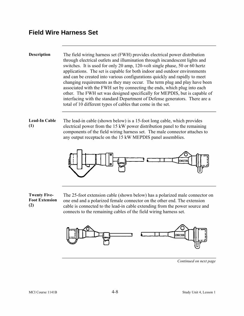
MCI Course 1141B 4-8 Study Unit 4, Lesson 1
Field Wire Harness Set
Description The field wiring harness set (FWH) provides electrical power distribution
through electrical outlets and illumination through incandescent lights and switches. It is used for only 20 amp, 120-volt single phase, 50 or 60 hertz applications. The set is capable for both indoor and outdoor environments and can be created into various configurations quickly and rapidly to meet changing requirements as they may occur. The term plug and play have been associated with the FWH set by connecting the ends, which plug into each other. The FWH set was designed specifically for MEPDIS, but is capable of interfacing with the standard Department of Defense generators. There are a total of 10 different types of cables that come in the set.
Lead-In Cable (1)
The lead-in cable (shown below) is a 15-foot long cable, which provides electrical power from the 15 kW power distribution panel to the remaining components of the field wiring harness set. The male connector attaches to any output receptacle on the 15 kW MEPDIS panel assemblies.
Twenty Five-Foot Extension (2)
The 25-foot extension cable (shown below) has a polarized male connector on one end and a polarized female connector on the other end. The extension cable is connected to the lead-in cable extending from the power source and connects to the remaining cables of the field wiring harness set.
Continued on next page
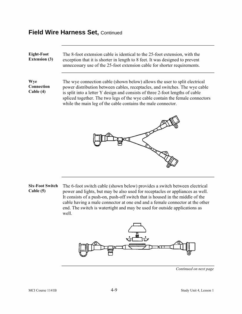
MCI Course 1141B 4-9 Study Unit 4, Lesson 1
Field Wire Harness Set, Continued
Eight-Foot Extension (3)
The 8-foot extension cable is identical to the 25-foot extension, with the exception that it is shorter in length to 8 feet. It was designed to prevent unnecessary use of the 25-foot extension cable for shorter requirements.
Wye Connection Cable (4)
The wye connection cable (shown below) allows the user to split electrical power distribution between cables, receptacles, and switches. The wye cable is split into a letter Y design and consists of three 2-foot lengths of cable spliced together. The two legs of the wye cable contain the female connectors while the main leg of the cable contains the male connector.
Six-Foot Switch Cable (5)
The 6-foot switch cable (shown below) provides a switch between electrical power and lights, but may be also used for receptacles or appliances as well. It consists of a push-on, push-off switch that is housed in the middle of the cable having a male connector at one end and a female connector at the other end. The switch is watertight and may be used for outside applications as well.
Continued on next page
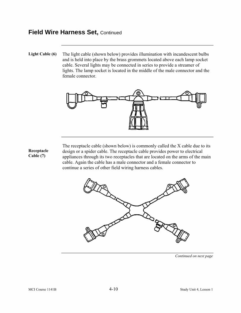
MCI Course 1141B 4-10 Study Unit 4, Lesson 1
Field Wire Harness Set, Continued
Light Cable (6) The light cable (shown below) provides illumination with incandescent bulbs
and is held into place by the brass grommets located above each lamp socket cable. Several lights may be connected in series to provide a streamer of lights. The lamp socket is located in the middle of the male connector and the female connector.
Receptacle Cable (7)
The receptacle cable (shown below) is commonly called the X cable due to its design or a spider cable. The receptacle cable provides power to electrical appliances through its two receptacles that are located on the arms of the main cable. Again the cable has a male connector and a female connector to continue a series of other field wiring harness cables.
Continued on next page

MCI Course 1141B 4-11 Study Unit 4, Lesson 1
Field Wire Harness Set, Continued
Generator Lead-In Cable (8)
The generator lead-in cable (shown below) connects the pigtailed end of the cable directly to any terminal or load studs of any type of generator. The ends of the generator lead-in cable are stripped, trimmed, tinned 2 inches at the ends, while the other end of the cable is molded with the female connector to run any series of field wiring cables.
Commercial Power Jumper Cable (9)
The commercial power jumper cable (shown below) adapts/connects to a commercial power supply. The molded plug will connect to any standard commercial wall or extension outlet, which allows electrical power to the field wiring harness set from an existing building or structure that has receptacle outlets. Note: The field wiring harness set is required to run on 20-amp 120-volt
system, so ensure that the electrical power you plug in is the same as the requirements of the FWH set. Any other type of electrical system may cause fire or damage to the harness set.
Continued on next page

MCI Course 1141B 4-12 Study Unit 4, Lesson 1
Field Wire Harness Set, Continued
Army Conversion Cable (10)
The Army conversion cable (shown below) adapts and connects to any of the Army general illumination light sets, and either allows the field wiring harness set to be operated from an Army power source, or allows the Army light sets to be powered from the field wiring harness set. The cable has a female connector at one end and an externally molded two-pole plug with a 3-inch ground wire extending from the cable at the other end.
Light Bulbs The light bulbs that are provided with the FWH set are packaged in four
impact resistant containers. The outer cover of each box is made of duck olive green material and is held closed with Velcro straps for easy access. Each box has a hinged lid and individual foam rubber compartments for storing up to 12 light bulbs. This durable container protects the bulbs during shipment and storage.
Continued on next page

MCI Course 1141B 4-13 Study Unit 4, Lesson 1
Field Wire Harness Set, Continued
Containerizing The field wiring harness set is stored in 13 nylon duffel bags that are labeled
to address the electrical requirements of tents used in the Marine Corps. The fabric tents are labeled as general purpose (GP), command post (CP), and maintenance tent. The set is comprised of 1 maintenance tent bag, 2 command post bags, and 10 general-purpose bags for a total of 13 bags. Each bag contains the correct amount of cables to provide electricity to the end user. The table below describes the type and quantity of cables in each bag:
Cable GP Tent Bag CP Tent Bag Maintenance Tent Cable # 1 1 1 N/A Cable # 2 1 N/A N/A Cable # 3 1 1 N/A Cable # 4 1 2 N/A Cable # 5 1 1 2 Cable # 6 3 2 6 Cable # 7 1 1 6 Cable # 8 1 1 1 Cable # 9 1 1 1 Cable # 10 1 1 1
Lighting Systems
Lighting systems, such as tents and existing infrastructure, can be challenging, especially when dealing with sensitive technology of high electronics. The use of the field wiring harness set detracts the use of this technology and may be harmful to causing electro-magnetic interference (EMI).
Continued on next page

MCI Course 1141B 4-14 Study Unit 4, Lesson 1
Field Wire Harness Set, Continued
Characteristics As technology advances, new electro-magnetic interference stringable shelter
lights (shown below) are used to reduce detection and interference and have the following characteristics: • Blackout filter greatly reduces visible signature to prevent compromising
peripheral electronics, computers, and medical equipment. • Lights operate independently, allowing any combination of lights to be on
or off. • Electronic ballast uses less current than magnetic ballast and produces
flicker free cool-to-the-touch light to produce 50 watts per light. • Patented floating bulb sockets protect the bulb from impact, extending
bulb life. It is fitted with a standard U.S. male and female plug system that can be connected to any generator with an output of 110 VAC.
• Straps are provided for easy one man installation into tents and shelters.
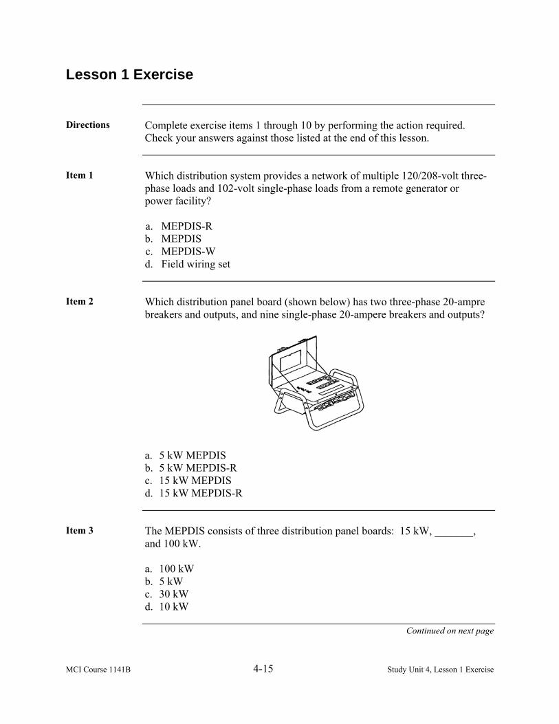
MCI Course 1141B 4-15 Study Unit 4, Lesson 1 Exercise
Lesson 1 Exercise
Directions Complete exercise items 1 through 10 by performing the action required.
Check your answers against those listed at the end of this lesson.
Item 1 Which distribution system provides a network of multiple 120/208-volt three-
phase loads and 102-volt single-phase loads from a remote generator or power facility? a. MEPDIS-R b. MEPDIS c. MEPDIS-W d. Field wiring set
Item 2 Which distribution panel board (shown below) has two three-phase 20-ampre
breakers and outputs, and nine single-phase 20-ampere breakers and outputs?
a. 5 kW MEPDIS b. 5 kW MEPDIS-R c. 15 kW MEPDIS d. 15 kW MEPDIS-R
Item 3 The MEPDIS consists of three distribution panel boards: 15 kW, _______,
and 100 kW. a. 100 kW b. 5 kW c. 30 kW d. 10 kW
Continued on next page

MCI Course 1141B 4-16 Study Unit 4, Lesson 1 Exercise
Lesson 1 Exercise, Continued
Item 4 The ___________ provides electrical power distribution through electrical
outlets and illumination through incandescent lights and switches. a. field wire harness set b. illumination set c. distribution panel d. distribution box
Item 5 Which cable provides electrical power from the 15 kW power distribution
panel to the remaining components of the field wiring harness set? a. 25-foot extension b. Lead-in cable c. Light cable d. Receptacle cable
Item 6 Through Item 10
Matching: For items 6 through 10, match the cable in column 1 to its description in column 2.
Column 1 Cable
Column 2
Description ____ 6. Wye Connection Cable ____ 7. Six-Foot Switch Cable ____ 8. Light Cable ____ 9. Receptacle Cable ____10. Commercial Power Jump
Cable
a. Adapts/connects to a commercial
power supply. b. Allows the user to split electrical
power distribution between cables, receptacles, and switches.
c. Provides power to electrical appliances through its two receptacles located on the arms of the main cable.
d. Provides a switch between electrical power and lights.
e. Provides illumination through the use of incandescent bulbs.
Continued on next page

MCI Course 1141B 4-17 Study Unit 4, Lesson 1 Exercise
Lesson 1 Exercise, Continued
Answers The table listed below lists the answers to the exercise items. If you have any
questions about these items, refer to the reference page.
Item Number Answer Reference 1 b 4-3 2 c 4-4 3 c 4-4 4 a 4-8 5 b 4-8 6 b 4-9 7 d 4-9 8 e 4-10 9 c 4-10 10 a 4-11

MCI Course 1141B 4-18 Study Unit 4, Lesson 1 Exercise
(This page intentionally left blank.)
MCI Course 1141B 4-19 Study Unit 4, Lesson 2
LESSON 2
MOBILE ELECTRIC POWER DISTRIBUTION SYSTEM-REPLACEMENT
Introduction
Scope The Mobile Electric Power Distribution System-Replacement (MEPDIS-R) is
a commercial-based modular component system of portable power distribution boxes and interconnecting power cables, capable of being configured in various ways to address the unique power and size requirements of the units when deployed. The system includes a series of cable adapters enabling the integration of legacy assets with next generation components. In addition, since the cable assembly package also includes pig tail sets of power input cables, the individual power distribution boxes can be energized either directly from the power source or from larger boxes up stream.
Learning Objectives
Upon completion of this lesson, you will be able to • Identify the Mobile Electric Power Distribution System-Replacement
(MEPDIS-R) power distribution boxes. • Identify the MEPDIS-R cable sets.
• Identify the steps to install the MEPDIS/MEPDIS-R into operation.
• Identify the use of an inventory sheet.
• Identify the symbols used to mark the inventory sheet.
In This Lesson This lesson contains the following topics:
Topic See Page Introduction 4-19 Distribution Boxes 4-20 Cables 4-28 Installation 4-33 Inspection and Inventory 4-34 Lesson 2 Exercise 4-37

MCI Course 1141B 4-20 Study Unit 4, Lesson 2
Distribution Boxes
Characteristics MEPDIS-R is composed of the 5 kW outdoor, 5 kW indoor, 15 kW, 30 kW,
100 kW, and 300 kW power distribution boxes; 13 cable sets; 2 cable spools of different sizes, and a cam-lock connection kit. Power distribution boxes (PDB) are interconnected with lightweight, multi-conductor cables with connectors sized by amperage, keyed for voltage and frequency, and capable of rapid connect/disconnect with other systems. It is also compatible with the legacy MEPDIS.
Replacement The field wiring harness will be replaced with the inclusion of the 5 kW
outdoor and 5 kW PDBs and their accompanying cable sets. These PDBs will distribute power to all tents and shelters, to include the Jameson Lighting System. Each MEPDIS-R power distribution box consists of four panel boards that are skid-mounted. Circuit breakers and wiring are enclosed in a water-resistant cabinet that is made of hardened rubber. The circuit breakers are accessed by raising the hinged cover. Input and output receptacles are protected by weatherproof covers. Note: This system is only used for 120/208 volt, 50/60 Hz applications. Do
not use for 240/416 volts or 400 Hz.
Continued on next page

MCI Course 1141B 4-21 Study Unit 4, Lesson 2
Distribution Boxes, Continued
5 kW Outdoor Power Distribution Box
The 5 kW outdoor power distribution box consists of a frame assembly, a circuit assembly, one 30-amp 3-phase pin and sleeve input connector, four side panels with nine receptacles, six 20-amp single-phase and three 30-amp single-phase receptacles, input power indicator lights, and the necessary cables for outdoor use. It can be directly fed from a 100k, 30k, or a 15k MEPDIS-R box. The outputs can feed up to six 20-amp single-phase 5k MEPDIS-R cord sets or “Y” cords, and up to three single-phase 30-amp receptacles.
Continued on next page

MCI Course 1141B 4-22 Study Unit 4, Lesson 2
Distribution Boxes, Continued
5 kW Indoor Power Distribution Box
The 5 kW indoor power distribution box consists of a frame assembly, a circuit assembly, one 30-amp, 30-phase pin and sleeve input connector, three side panels with nine ground fault circuit interrupter (GFCI) duplex receptacles, one panel with input power indicator lights, and the necessary cables for indoor use. It can be directly fed from either a 100k box, 30k box, or a 15k box. The nine 20-amp single-phase GFCI duplex receptacles can be used to feed up to nine 5k MEPDIS-R indoor cord sets or additional equipment.
Continued on next page

MCI Course 1141B 4-23 Study Unit 4, Lesson 2
Distribution Boxes, Continued
15 kW Power Distribution Box
The 15 kW power distribution box consists of a frame assembly, a circuit assembly, two each 60-amp three-phase input connectors, four side panels with receptacles, and input power indicator lights. It can be directly fed either from a 100k, 30k, or up to two synchronized 60-amp three-phase external power sources, independently or simultaneously. The outputs can be used to feed up to four 30-amp three-phase 5k MEPDIS-R boxes and up to four 20- amp single-phase 5k MEPDIS-R outdoor cord sets or “Y” cords, and has one 20-amp GFCI duplex receptacle.
Continued on next page

MCI Course 1141B 4-24 Study Unit 4, Lesson 2
Distribution Boxes, Continued
30 kW Power Distribution Box
The 30 kW power distribution box consists of a frame assembly, a circuit assembly, two each 100-amp three-phase input connectors, four side panels with receptacles and input power indicator lights. It can be directly fed from either a 300k or a 100k MEPDIS-R box or up to two 100-amp three-phase external power sources, independently or simultaneously. The outputs can be used to feed up to four 60-amp three-phase 15k MEPDIS-R boxes, up to two 30-amp three-phase 5k MEPDIS-R boxes, up to two 20-amp three-phase outlets, up to two 20-amp single-phase 5k MEPDIS-R outdoor cord sets or “Y” cords, and has one 20-amp GFCI duplex receptacle.
Continued on next page
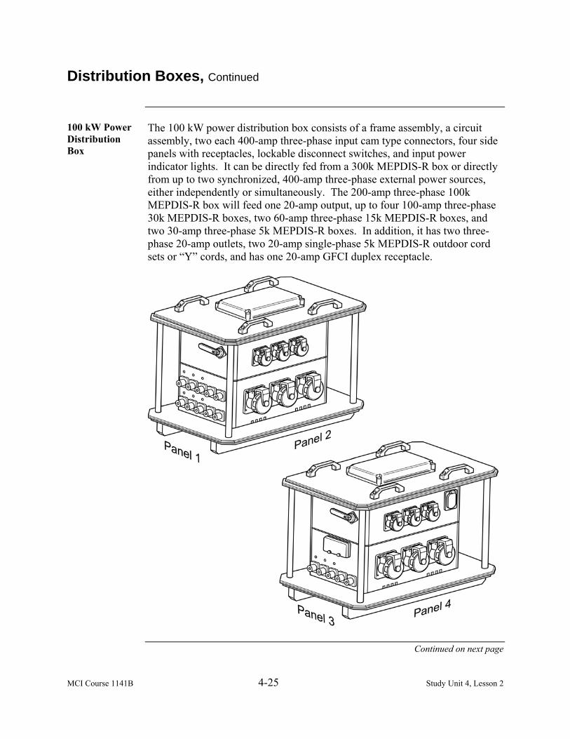
MCI Course 1141B 4-25 Study Unit 4, Lesson 2
Distribution Boxes, Continued
100 kW Power Distribution Box
The 100 kW power distribution box consists of a frame assembly, a circuit assembly, two each 400-amp three-phase input cam type connectors, four side panels with receptacles, lockable disconnect switches, and input power indicator lights. It can be directly fed from a 300k MEPDIS-R box or directly from up to two synchronized, 400-amp three-phase external power sources, either independently or simultaneously. The 200-amp three-phase 100k MEPDIS-R box will feed one 20-amp output, up to four 100-amp three-phase 30k MEPDIS-R boxes, two 60-amp three-phase 15k MEPDIS-R boxes, and two 30-amp three-phase 5k MEPDIS-R boxes. In addition, it has two three-phase 20-amp outlets, two 20-amp single-phase 5k MEPDIS-R outdoor cord sets or “Y” cords, and has one 20-amp GFCI duplex receptacle.
Continued on next page

MCI Course 1141B 4-26 Study Unit 4, Lesson 2
Distribution Boxes, Continued
300 kW Power Distribution Box
The 300 kW power distribution box consists of a frame assembly, a circuit assembly, three each 400-amp three-phase input cam type connectors, four side panels with receptacles, lockable disconnect switches, and input power indicator lights. It can be directly fed by three synchronized, 400-amp, three- phase external power sources, either independently or simultaneously. The 400-amp, three-phase outputs can be used to feed additional equipment, or up to 100k MEPDIS-R boxes or 100-amp three-phase 30k MEPDIS-R boxes, and has 20-amp GFCI duplex receptacle.
Continued on next page

MCI Course 1141B 4-27 Study Unit 4, Lesson 2
Distribution Boxes, Continued
Balancing Loads
Generators supply balanced power. The generator attempts to supply the required power to satisfy the load on each phase. The three-phase loads are automatically balanced by the generator. The single-phase loads are not automatically balanced and must be balanced by the electrician. If the system is not balanced, the following can occur: • System voltage regulation becomes poor, since unbalancing causes high
voltage on the lightly loaded phases and low voltage on the heavily loaded phases.
• Prolonged unbalanced operation will damage and cause the generators to
malfunction. To balance the single-phase loads, follow the steps below:
Step Action 1 Total all three-phase demand amperes and list them on a phase
balancing worksheet (shown below). 2 Divide them by three. This will give you the single-phase
amperes for each phase to balance the phases as close to perfect as you can.
3 List the balances on the phase balancing worksheet. Phases must be balanced within a plus or minus of 10%.
Example The following is an example of a completed worksheet:
Item Phase 1 Phase 2 Phase 3
CO’s Tent 5 amps Sgt Majors Tent 5 amps Company Office Tent 15 amps Conference Tent 10 amps Medical Tent 10 amps Total Current Per Phase 15 amps 15 amps 15 amps
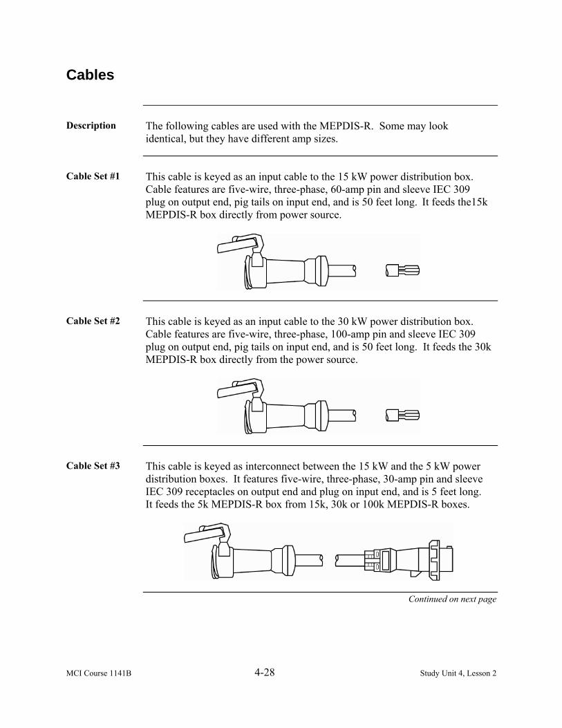
MCI Course 1141B 4-28 Study Unit 4, Lesson 2
Cables
Description The following cables are used with the MEPDIS-R. Some may look
identical, but they have different amp sizes.
Cable Set #1 This cable is keyed as an input cable to the 15 kW power distribution box.
Cable features are five-wire, three-phase, 60-amp pin and sleeve IEC 309 plug on output end, pig tails on input end, and is 50 feet long. It feeds the15k MEPDIS-R box directly from power source.
Cable Set #2 This cable is keyed as an input cable to the 30 kW power distribution box.
Cable features are five-wire, three-phase, 100-amp pin and sleeve IEC 309 plug on output end, pig tails on input end, and is 50 feet long. It feeds the 30k MEPDIS-R box directly from the power source.
Cable Set #3 This cable is keyed as interconnect between the 15 kW and the 5 kW power
distribution boxes. It features five-wire, three-phase, 30-amp pin and sleeve IEC 309 receptacles on output end and plug on input end, and is 5 feet long. It feeds the 5k MEPDIS-R box from 15k, 30k or 100k MEPDIS-R boxes.
Continued on next page

MCI Course 1141B 4-29 Study Unit 4, Lesson 2
Cables, Continued
Cable Set #4 This cable is keyed as interconnect between the 30 kW and the 15 kW power
distribution boxes. It features five-wire, three-phase, 60-amp pin and sleeve IEC 309 receptacles on output end and plug on input end, and is 50 feet long. It feeds 15k MEPDIS-R boxes directly from 100k or 30k MEPDIS-R boxes.
Cable Set #5 This cable is keyed as interconnect between the 100 kW and the 30 kW power
distribution boxes. It features five-wire, three-phase, 100-amp pin and sleeve IEC 309 receptacles on output end and plug on input end, and is 50 feet long. It feeds 30k MEPDIS-R boxes from 300k power distribution box or 100k MEPDIS boxes.
Cable Set #6 This cable is a single-wire, 400-amp, cam type 16 female on one end of each
wire and male connector on the other end that is 25 feet long, one each of five different colors. It feeds 300k or 100k MEPDIS/MEPDIS-R boxes.
Continued on next page

MCI Course 1141B 4-30 Study Unit 4, Lesson 2
Cables, Continued
Cable Set #7 This cable is keyed as interconnect between the 100-amp legacy MEPDIS to
the new 100 kW power distribution box. Cable features are five-wire, three-phase, 100-amp pin and sleeve IEC 309 receptacle on output end and five-wire, three-phase, 100-amp, amphenol plug on input end, and is 3 feet long.
Cable Set #8 This cable is keyed as interconnect between the 100-amp power distribution
box to the legacy MEPDIS. Cable features are five-wire, three-phase, 100- amp pin and sleeve IEC 309 receptacle on input end and five-wire, three-phase, 100-amp, amphenol plug on output end, and is 3 feet long.
Cable Set #9 This cable is keyed as interconnect between the 60-amp legacy MEPDIS to
the new power distribution box. Cable features are five-wire, three-phase, 60- amp pin and sleeve IEC 309 receptacle on output end and five-wire, three-phase, 100-amp, amphenol plug on input end, and is 3 feet long.
Continued on next page

MCI Course 1141B 4-31 Study Unit 4, Lesson 2
Cables, Continued
Cable Set #10 This cable is keyed as interconnect between the 60-amp new power
distribution box to the legacy MEPDIS. Cable features are five-wire, three-phase, 60-amp pin and sleeve IEC 309 receptacle on input end and five-wire, three-phase, 100-amp, amphenol plug on output end, and is 3 feet long.
Cable Set #11 The Y cable is a 50-foot Y configuration, 20-amp plugs with two 25-foot
legs, each with two 5 to 15R receptacles. Each cord set is 75 feet long. This cable is used in conjunction with the 5 kW outdoor power distribution box.
Cable Set #12 The 5 kW indoor cables are 50 feet long, 6 to 20 plugs to 5 to 15R receptacles
with four each, 15-amp receptacles and is deployed in a tent or sheltered environment. These cables will be fielded with the 5 kW indoor PDB.
Continued on next page

MCI Course 1141B 4-32 Study Unit 4, Lesson 2
Cables, Continued
Cable Set #13 The 5 kW outdoor cables are 50 feet long, 6 to 20-amp plug with 4 each, and
15-amp receptacles. It provides power to tent lighting, conveniences, or other equipment. These cables will be fielded with the 5 kW outdoor PDB.
Cam Type Connector Kit
A cam type connector kit is available for the MEPDIS-R. The kit contains commercially available connectors, components and tools necessary to assemble power pigtails in the field (does not include the cable). It also contains new components that can be used to replace worn MEPDIS-R components and a male-to-female cam connector splitter so power may be branched off.
Determining Cables
Based on the distribution panels that are selected, determine which cables to use for the mission to include the types of connections, and the distance from the power source to the end user of the electricity. Cables are classified by amperes and can be classified by size and diameter in relation to their current carrying capacity. The cable diameters are listed by the American Wire Gauge (AWG). The table below depicts the amperage in relation to its cable size or gauge.
AMPERAGE GAUGE/DIAMETER 350 amperage cable 250 MCM 100 amperage cable # 2 AWG 60 amperage cable # 4 AWG 30 amperage cable # 8 AWG 20 amperage cable # 10 AWG
20 amperage field wiring # 12 AWG 15 amperage field wiring # 14 AWG

MCI Course 1141B 4-33 Study Unit 4, Lesson 2
Installation
Installing MEPDIS/ MEPDIS-R
When ready to install MEPDIS/MEPDIS-R into operation, follow the steps below:
Step Action 1 Turn off all electrical equipment and circuit breakers on panels.
Ensure that all distribution panels are properly grounded. 2 Connect the lead-in power cable to the input receptacle of each
corresponding panel. 3 Attach appropriate output cables from each output connector to
the next electrical component or load. 4 Ensure that the cable ends enter the connectors in the correct
sequence of connection based on the ends of the cables and connectors.
5 Tighten or ensure that the connectors are firmly fastened to the electrical panel.
6 Once all cables have been connected, set the main circuit breaker switch to the “ON” position.
7 Switch the output circuit breakers to the “ON” position, and monitor the phase indicator lights to verify that the electrical distribution panel is functioning properly.
8 Repeat the steps at the next power distribution panel.

MCI Course 1141B 4-34 Study Unit 4, Lesson 2
Inspection and Inventory
Stock Listing (SL-3)
Both MEPDIS and MEPDIS-R have publications that are labeled as Stock Listings or SL-3 that list all components and accessories for both sets of distribution equipment. Each SL-3 has a preface page that provides important information for the user to know when inventorying the equipment. It is important to review this material, as it will assist in properly inventorying your equipment, and ensuring that the equipment is serviceable and ready for rapid deployment.
Inventory Sheet According to Marine Corp Orders P4790.2 and P4400.150, use either the
inventory sheet that is attached with the SL-3 or a local generated form or extract that maintains the information on the SL-3 inventory sheet. At a minimum, it would provide the information of a national stock number or part number, unit of issue, and its quantity. An example of an SL-3 inventory sheet is shown below from the MEPDIS-R SL-3 extract.
SL-3-6116/1 COMPONENTS STOCKLIST SL-3-6115/1 DATED: ______________ SERIAL NO. OF END ITEM: ______________ TOOL BOX # _________ END ITEM: 5 kW Outdoor Panel INVENTORY SHEET
1 2 3 4 5 6 7 8 9
ITEM NO
NSN
FOG-KEY REF
DESG
MODEL
ITEM IDENTIFICATION
U/M
QTY
PERIODIC INVENTORY (In
accordance with MCO P4790.2_ and MCO P
4400.150_ or as directed by the Unit
Commander)
REMARKS
SUPPLY SYSTEM RESPONSIBILITY
1 6150-01-530-7532
007-001
CABLE ASSEMBLY, SPECIAL PURPOSE, ELECTRICAL; P/N
DB20QD50SEPS, CAGE 00Y95
EA 6
2 5935-01-425-3924
007-002
CONNECTOR, PLUG, ELECTRICAL; 30-AMP,
SINGLE-PHASE, STRAIGHT SHAPE, EXTERNAL
COUPLING W.STRAIN RELIEF; P/N 330P4W, CAGE
74545
EA 3
3 61500-01-540-3519
007-003
“Y” CABLE ASSEMBLY, ELECTRICAL; P/N
2FERQUAD-USMC, CAGE 00Y95
EA 3

MCI Course 1141B 4-35 Study Unit 4, Lesson 2
Inspection and Inventory, Continued
Inventory When conducting the inventory of either distribution systems, use distinct
markings to identify the proper status of the item, which is, derived from the TM 4700-15/1H. The following markings are listed below:
– Complete, satisfactory, or serviceable. M – Missing end item not accounted for. R – Repair required. Some end items may not need to be replaced, just
repaired. U – Unserviceable. The end item is beyond either repair or is incapable of
being repaired. Note: As a Marine electrician, ensure equipment is complete and ready for
whatever the mission may require. Keeping a good inventory of your equipment and ensuring that it is kept in serviceable condition is the correct step to accomplish any mission or requirement.

MCI Course 1141B 4-36 Study Unit 4, Lesson 2
(This page intentionally left blank.)

MCI Course 1141B 4-37 Study Unit 4, Lesson 2 Exercise
Lesson 2 Exercise
Directions Complete exercise items 1 through 6 by performing the action required.
Check your answers against those listed at the end of this lesson.
Item 1 The MEPDIS-R is composed of six power distribution boxes: 5 kW outdoor,
5 kW indoor, 15 kW, _____ kW, 100 kW, and 300 kW power distribution boxes. a. 20 b. 30 c. 150 d. 200
Item 2 Which cable set is keyed as an input cable to the 15 kW power distribution
box? a. #1 b. #2 c. #3 d. #4
Item 3 Which cable set features five-wire, three-phase, 100-amp pin and sleeve IEC
309 receptacles on output end and plug on input end, and is 50-feet long? a. #2 b. #4 c. #5 d. #6
Item 4 To install MEPDIS/MEPDIS-R into operation, connect the _________ power
cable to the input receptacle of each corresponding panel. a. lead-in b. 6-foot switch c. jump d. wye connection
Continued on next page

MCI Course 1141B 4-38 Study Unit 4, Lesson 2 Exercise
Lesson 2 Exercise, Continued
Item 5 Having the nomenclature of the item, its national stock number or part
number, unit of issue, and its quantity are the minimum requirements located on the a. Inventory Sheet. b. Equipment Repair Order. c. Equipment Repair Order Shopping List. d. Lubrication Instructions.
Item 6 Using an inventory sheet and conducting an inventory on MEPDIS, what
marking would you annotate for an item that requires repair for a 100 kW panel? a. X b. R c. M d. U
Continued on next page

MCI Course 1141B 4-39 Study Unit 4, Lesson 2 Exercise
Lesson 2 Exercise, Continued
Answers The table listed below lists the answers to the exercise items. If you have any
questions about these items, refer to the reference page.
Item Number Answer Reference 1 b 4-20 2 a 4-28 3 c 4-29 4 a 4-33 5 a 4-34 6 b 4-35

MCI Course 1141B 4-40 Study Unit 4, Lesson 2 Exercise
(This page intentionally left blank.)

MCI Course 1141B 4-41 Study Unit 4, Lesson 3
LESSON 3
BUS BAR
Introduction
Scope A bus bar is a fabricated distribution center using the general light sets and
the lineman’s tool kit. It is used
• When the equipment requiring power is so widely scattered that two or more branch feeders are required.
• To connect two or more generator sets in parallel if the load requirements are greater than what a single generator set can supply.
• When one generator set can be brought on line simultaneously as one is dropped off line by the use of a single pole double throw switch if a service is needed or if something goes wrong with a generator set.
Learning Objectives
Upon completion of this lesson, you will be able to • Identify the steps to setup a bus bar. • Identify the types of ground. • Identify the method to connect a generator to a bus bar. • Identify the different types of ties. • Identify the use of a pigtail wire splice.
In This Lesson This lesson contains the following topics:
Topic See Page Introduction 4-41 Construction 4-42 Grounding 4-45 Connections 4-46 Ties 4-47 Wire Splices 4-49 Twisting Wire Splices 4-51 Lesson 1 Exercise 4-53

MCI Course 1141B 4-42 Study Unit 4, Lesson 3
Construction
Introduction Using the general illumination light sets, a bus bar (distribution system) can
be fabricated. A bus bar (shown below) is made using the following six essential items: • Lineman’s Tool Kit • Grounding Rod • Insulator Racks • Appropriate Size Wire • Appropriate Switch Boxes and Breaker Boxes • Lumber 2 (4x4s) and 1 (2x4)
GENERATORINCOMING CABLESL1,L2,L3,&L0
6 FT
3 FT
5 FTL1L2
L3L0
FRONT VIEW OF BUS BAR
SWITCH BOX
OFF
ON
GROUND WIRE6 AWG
4X4
2X4
INSULATOR RACKS
9 FTGROUNDROD
Setup Setting up the bus bar starts with the general guidelines in the illustration
above, and the following steps provided on the next page. Keep in mind that these are the minimum guidelines for construction of a bus bar. The bus bar can be made as elaborate as safety, time, materials, and your imagination.
Continued on next page

MCI Course 1141B 4-43 Study Unit 4, Lesson 3
Construction, Continued
Setup, continued
Follow the steps below to setup the bus bar.
Step Action 1 Dig two holes 3 feet deep, 5 feet apart and set the 4x4s in the
ground. 2 Using a 2x4, nail a top brace cross member to the posts to make the
framework sturdy. 3 Use lag bolts to mount insulator racks provided by the large and
small light set(s). Ensure that they are evenly spaced on the inside of each 4x4 so that the insulator racks face each other.
4 Ensure that the wire is tight as possible using a dead end tie. The size wire will be determined by the generator capacity and the power requirements. Note: The wiring for the bus bar must be strung between the 4x4s
using the insulator racks. 5 Place a grounding rod about 1 foot from the bus bar and drive it
into the ground to the proper depth of 8 to 8½ feet. Then connect it to the neutral (LO) wire. The wire size will be determined by the wire size that is on the bus bar.
6 Once the wire has been positioned, mark each wire with tape or some other non-conducting material so the phases can be identified. Remember, the bus bar is the main connection point for all combined power. The wire must be able to handle the entire load of the area being powered up.
Switch Boxes Once you have completed the bus bar, add a switch box to the frame. Switch
boxes are provided in the large and small light set(s). The switch box is used for connecting and disconnecting generator(s). It is also a safety measure because all power can be shut off from the bus bar and the area being provided power. Have the proper size switch box for your bus bar because your switch box will be required to handle the same amount of power that your wire used on the bus bar handles.
Large Light Set Large light set contains a one 70-ampere circuit breaker box with 15 and 30
ampere circuit breakers to provide over current protection for circuits.
Continued on next page

MCI Course 1141B 4-44 Study Unit 4, Lesson 3
Construction, Continued
Small Light Set The small light set provides three 30-ampere breaker boxes with 15- and
30-ampere breakers. The light set also provides one 100 and three 60-ampere single-throw single-pole three-phase switch boxes. These switch boxes are to be used as the primary over current protection for our main circuits and feeder circuits.

MCI Course 1141B 4-45 Study Unit 4, Lesson 3
Grounding
Equipment Ground
An equipment ground is an additional ground that is attached to all metal frames and surfaces of appliances and circuit devices. It reduces the voltage to zero volts if a fault does occur in a circuit. The fuse or circuit breaker will open the circuit to prevent serious injury to any one who might come in contact with a metal surface of the appliance or device.
System Ground A system ground is the ground applied to the neutral conductor. It reduces
the possibility of fire and shock by reducing the voltage to zero volts. System grounding protects a circuit and attached appliances from lightning, line surges, and contact with higher voltages. The neutral wire, which is used for system grounding must be connected to a grounding bus bar within the circuit breaker or fuse box. This is done by a bonding screw that secures the grounding bus bar to the box. The entire grounding system is then bonded to the ground by attaching a #6 AWG or #8 AWG copper wire to the grounding bus bar and running it to a grounding rod. The grounding rod is 9 feet long and at least 8 feet must be driven into the ground.
Grounding the Bus Bar
To ground the bus bar to the system, use #4 AWG wire. Once you have the wire, connect the wire to the grounding rod. Drive the grounding rod in the ground at least 8 feet. To connect the wire to the bus bar and grounding rod, use a splice connector that is located in the light set. Ensure that you have continuity between the bus bar and grounding rod. WARNING: Bad continuity could cause loss or damage to life or
equipment.
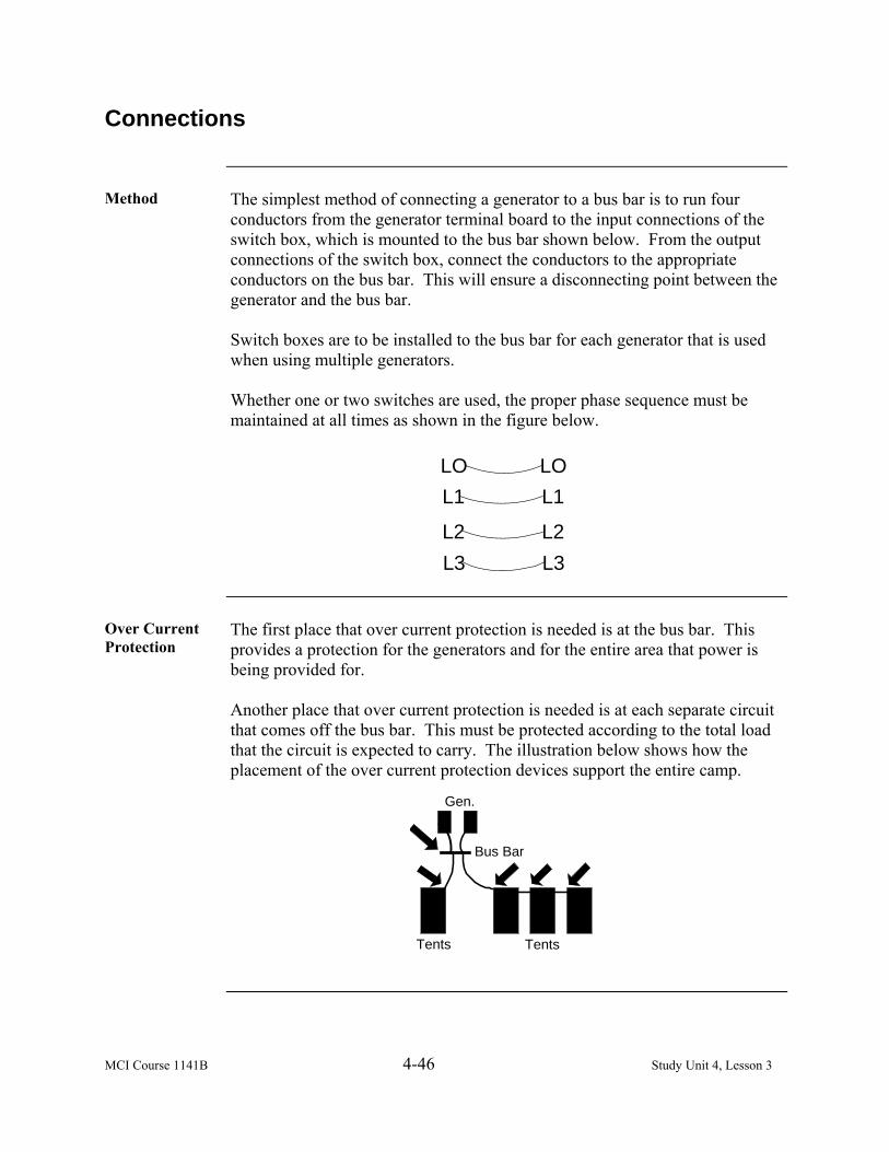
MCI Course 1141B 4-46 Study Unit 4, Lesson 3
Connections
Method The simplest method of connecting a generator to a bus bar is to run four
conductors from the generator terminal board to the input connections of the switch box, which is mounted to the bus bar shown below. From the output connections of the switch box, connect the conductors to the appropriate conductors on the bus bar. This will ensure a disconnecting point between the generator and the bus bar. Switch boxes are to be installed to the bus bar for each generator that is used when using multiple generators. Whether one or two switches are used, the proper phase sequence must be maintained at all times as shown in the figure below.
LOL1
L2L3
LOL1
L2L3
Over Current Protection
The first place that over current protection is needed is at the bus bar. This provides a protection for the generators and for the entire area that power is being provided for. Another place that over current protection is needed is at each separate circuit that comes off the bus bar. This must be protected according to the total load that the circuit is expected to carry. The illustration below shows how the placement of the over current protection devices support the entire camp.
Gen.
Bus Bar
TentsTents

MCI Course 1141B 4-47 Study Unit 4, Lesson 3
Ties
Side A side tie is used for supporting the conductor when it is not feasible to run
the conductor through the insulator racks. Example: If you are running your conductor over your tents and one of the
tents needs to be moved, you will have a problem with the insulator still being on the conductor. This will cause a problem because of the extra weight that it would bring on the conductor.
Side ties are used with a small piece of #14 AWG wire about 6-8 inches long. You then run two wires through the insulator rack wrapping the wires around the insulator rack once pulling firmly. Once the wires are around the insulator rack, wrap the extra wire around the conductor that is running through the insulator rack. Make several wraps around the conductor that is running through the insulator as shown below. This will ensure a good firm hold.
Corner A corner tie is used for supporting the conductor when support is needed at
direction changes. Example: If you are running your conductor from your bus bar up to an
insulator rack on a pole and you have to continue to another pole, a corner tie would be needed to support the conductor at the insulator rack. This gives the conductor support from moving around and possibly causing damage. Corner ties are used in the same manner as the side tie with exception of it being a corner.
Continued on next page

MCI Course 1141B 4-48 Study Unit 4, Lesson 3
Ties, Continued
Corner, continued
Corner ties are used with a small piece of #14 AWG wire about 6 to 8 inches long too. Run two wires through the insulator rack, wrapping the wires around the insulator rack once pulling firmly. Once the wires are around the insulator rack, wrap the extra wire around the conductor that is running through the insulator rack. Make several wraps around the conductor that is running through the insulator as shown below. This will ensure a good firm hold.
Dead End Dead end ties work like an anchor point where stress and tension are
unavoidable. To make a dead end tie, you only need the insulator rack and the conductor as shown below.
To make a dead end tie, wrap the conductor around the insulator twice. Once this is accomplished, wrap the remaining conductor around the supporting conductor several times to ensure a firm tie.

MCI Course 1141B 4-49 Study Unit 4, Lesson 3
Wire Splices
Pigtail Splice A pigtail slice is a type of connection made between two electric conductors;
formed by placing the ends of the conductors side by side and then twisting the ends of the two conductors around one another.
Joining the Wire
When joining electrical wires used to carry current in a home, use a solderless twist-on connector. The length of wire needed to strip insulation depends on the number of wires being joined together and the size of the twist-on connector you are going to use. In good practice, do not strip off too much insulation. When the splice is completed and the twist-on connector is installed, you will not see any bare wire exposed extending beneath the bottom edge of the mechanical connector.
Stripping the Wire
If you are stripping wires that are not part of the building’s electrical system, such as speaker wires, you may not be using a mechanical connector, just tape. Again, the length of wire that you need to strip depends on the number of wires being joined, and your ability to twist them securely together.
Nicking the Wire
Do not damage the wire during stripping of insulation. Be careful not to nick the metal wire when cutting the insulation in preparation to strip it off. If you do nick the wire, the risk is that the nicked ends will later break off, destroying your connection and becoming unsafe. If you accidentally nick the wire, cut the nicked portion of the wire end off and start over.
Splicing Three or More Wires
The pigtail type of splice is best when joining three or more wires. The thing to guard against when more than two wires are involved in the twist is the tendency for one or more of the wires remain straight while the others are wrapped around it. When this happens, the straight conductors can be pulled free of the splice fairly readily. To prevent this, ensure the twist is started with all the wires bent at approximately a right angle. Note: Do not bend current-conducting electrical wires at a sharp angle. If the bent wires are interlocked and held with pliers, the twist will continue as started.
Continued on next page

MCI Course 1141B 4-50 Study Unit 4, Lesson 3
Wire Splices, Continued
Starting a Three-Wire Pigtail Splice
To interlock all three wires, bend each one at a right angle when you make the first twist. A straight wire will pull out under little stress.
Testing a Three-Wire Pigtail Splice
Check that all of your wires participated in the twist by pulling each individually. Make this check before applying your mechanical connector such as a twist-on.
Finishing the Three-Wire Pigtail Splice
Finish the three-wire pigtail splice by securing it with a mechanical connector.
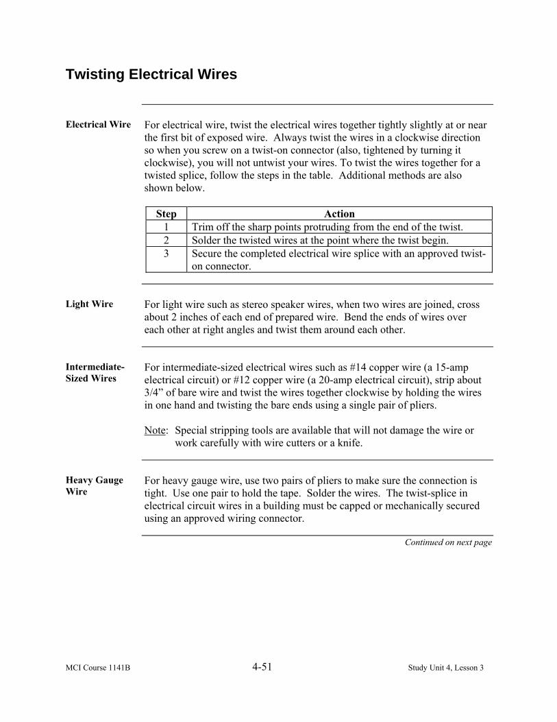
MCI Course 1141B 4-51 Study Unit 4, Lesson 3
Twisting Electrical Wires
Electrical Wire For electrical wire, twist the electrical wires together tightly slightly at or near
the first bit of exposed wire. Always twist the wires in a clockwise direction so when you screw on a twist-on connector (also, tightened by turning it clockwise), you will not untwist your wires. To twist the wires together for a twisted splice, follow the steps in the table. Additional methods are also shown below.
Step Action
1 Trim off the sharp points protruding from the end of the twist. 2 Solder the twisted wires at the point where the twist begin. 3 Secure the completed electrical wire splice with an approved twist-
on connector.
Light Wire For light wire such as stereo speaker wires, when two wires are joined, cross
about 2 inches of each end of prepared wire. Bend the ends of wires over each other at right angles and twist them around each other.
Intermediate-Sized Wires
For intermediate-sized electrical wires such as #14 copper wire (a 15-amp electrical circuit) or #12 copper wire (a 20-amp electrical circuit), strip about 3/4” of bare wire and twist the wires together clockwise by holding the wires in one hand and twisting the bare ends using a single pair of pliers. Note: Special stripping tools are available that will not damage the wire or
work carefully with wire cutters or a knife.
Heavy Gauge Wire
For heavy gauge wire, use two pairs of pliers to make sure the connection is tight. Use one pair to hold the tape. Solder the wires. The twist-splice in electrical circuit wires in a building must be capped or mechanically secured using an approved wiring connector.
Continued on next page

MCI Course 1141B 4-52 Study Unit 4, Lesson 3
Twisting Electrical Wires, Continued
Twist-On Connectors
“Wire Nut” is a trademarked name for a brand of twist-on connectors. Twist-on connectors come in different color-coded sizes. Choose the proper twist-on connector, depending on the thickness (gauge) of the wire and the number of wires you are combining in your splice. Place the connector over the end of your twisted splice, pressed onto the wires, and turn clockwise until it is tight. Notes: Be careful when pushing an electrical splice back into the junction
box. Do not loosen the connector you installed or your connection will be poor and possible unsafe. Using the wrong type of electrical splice connector, or one with poor performance can lead to a melted of failed electrical connection, possible risking shock of fire.
Special Approved Connectors
Electrical wires in a building are sometimes joined without twisting wires together. Instead, special approved connectors are used. The AlumiConn is used to splice a copper “pigtail” wire together with one or two aluminum wires to reduce fire hazard associated with aluminum electrical wiring.

MCI 1141B 4-53 Study Unit 4, Lesson 3 Exercise
Lesson 3 Exercise
Directions Complete exercise items 1 through 7 by performing the action required.
Check your answers against those listed at the end of this lesson.
Item 1 To setup the bus bar, dig ______ holes ___ feet deep, 5 feet apart and set the
4x4s in the ground. a. two, 3 b. three, 2 c. two, 2 d. four, 3
Item 2 Which type of ground is attached to all metal frames and surfaces of
appliances and circuit devices? a. system b. metal c. equipment d. circuit
Item 3 Which type of ground is applied to the neutral conductor and reduces the
possibility of fire and shock by reducing the voltage to zero volts? a. metal b. system c. circuit d. equipment
Item 4 To connect a generator to a bus bar, run _______ conductors from the general
terminal board to the input connections of the switch box, which is mounted to the bus bar. a. five b. three c. two d. four
Continued on next page
MCI 1141B 4-54 Study Unit 4, Lesson 3 Exercise
Lesson 3 Exercise, Continued
Item 5 If you are running your conductor from your bus bar up to an insulator rack
on a pole and you have to continue to another pole, which tie would be needed to support the conductor at the insulator rack? a. corner tie b. side tie c. dead end tie d. front tie
Item 6 The __________ tie is used for supporting the conductor when it is not
feasible to run the conductor through the insulator racks. a. front b. side c. corner d. dead end
Item 7 A ___________ is used to make a connection between two electric
conductors; formed by placing the ends of the conductors side by side and then twisting the ends of the two conductors around one another. a. pigtail slice b. ragtail slice c. side tie d. dead end tie
Continued on next page

MCI 1141B 4-55 Study Unit 4, Lesson 3 Exercise
Lesson 3 Exercise, Continued
Answers The table listed below lists the answers to the exercise items. If you have any
questions about these items, refer to the reference page.
Item Number Answer Reference 1 a 4-43 2 c 4-45 3 b 4-45 4 d 4-46 5 a 4-48 6 b 4-47 7 a 4-49

MCI 1141B 4-56 Study Unit 4, Lesson 3 Exercise
(This page intentionally left blank.)

MCI Course 1141B 5-1 Study Unit 5
STUDY UNIT 5
TOOLS
Overview
Scope As the history and advancement of electricity has grown, so has the close
relationship of tools. Tools are a unique source of our development and continued technology of electricity. Without tools, we would be incapable of performing many of the basic functions that are required for maintaining the equipment that generates electricity. This study unit will emphasize the current tools and kits and the test measuring equipment used in the Marine Corps.
In This Study Unit
This study unit contains the following lessons:
Lesson See Page Lineman Toolkit 5-3 Test Measuring Equipment 5-9

MCI Course 1141B 5-2 Study Unit 5
(This page intentionally left blank.)

MCI Course 1141B 5-3 Study Unit 5, Lesson 1
LESSON 1
LINEMAN TOOLKIT
Introduction
Scope As a Marine electrician, you need to know the types of tools that you will be
using. Knowing their capabilities and limitations will help ensure you can complete any electrical mission requested. In this lesson, we will identify the current toolkit (lineman) used by electricians in the Marine Corps. You will be able to identify, check serviceability and condition, and perform preventive maintenance to ensure all tools are capable of performing.
Learning Objectives
Upon completion of this lesson, you will be able to
• Identify the use of tools in the lineman’s toolkit.
• Identify the guidelines to inspect tools for serviceability and damage.
In This Lesson This lesson contains the following topics:
Topic See Page
Introduction 5-3 Components 5-4 Serviceability 5-5 Lesson 1 Exercise 5-7
MCI Course 1141B 5-4 Study Unit 5, Lesson 1
Components
Toolkit Description
The lineman’s toolkit is a standardized kit that provides a wide range of necessary tools for the basic electrician. This kit will enable electrician Marines at the organizational level to install, operate and maintain heating equipment, mobile electric power generating sources, electrical distribution systems, and the repair of telephone and telegraph wire. The tools in the kit (listed below) are warranted for the life and are configuration controlled. • Screwdrivers (both cross and flat tip) • Pocketknife • Tape measure (25 foot) • Tool pouch • Pliers diagonal (wire cutter or dykes) • Solenoid voltage tester (capable of testing both alternating current and
direct current) • Hammer double face • Pliers long nose (needlenose pliers) • Pliers channel lock • Wire stripper • Pliers, lineman (TL’s or lineman’s tool) • Cordless drill 18-volt by DeWalt with additional 18-volt rechargeable
battery and single face battery charger • Drill bit set twist • Masonry drill bit set • Auger drill bits • Hex key set (Allen wrench set with standard sizes) • Multimeter by Fluke (contains amp probes and a clamp on current probe
for measuring amperage)

MCI Course 1141B 5-5 Study Unit 5, Lesson 1
Serviceability
Guidelines A Marine electrician must know the importance of preserving and taking
stewardship of their tools. If you allow your tools to become worn or severely damaged, they will not function or operate correctly, especially when you need them during an immediate crisis. When inventorying the lineman’s toolkit, ensure accountability of the tools, inspect the serviceability of the tools, and ensure that they are functioning properly. Listed below are some guidelines to follow when inspecting tools: • Inspect each tool to ensure there is no rust or corrosion that will cause
deterioration of the tools. • Inspect for cuts or imperfections with the tools, especially those tools that
have cutting edges, drill bits, and pliers’ blades. • Check and clean tools that require calibration or require power to provide
maximum performance.
Preventive Maintenance
Maintaining tools requires some aspect of cleaning tools. The tools in the kit are all capable of being cleaned, and aids in preserving the item by using a cleaning solvent, such as WD-40. Keeping tools free from debris and dirt will prolong their life and allow the Marine electrician to continue to perform the mission.
Conducting Inventory
When conducting inventories for tool kits, inventories additional equipment for generators, and any other inventory, you should consult the Marine Corps Technical Manual TM-4700-15/1H for inventory procedures and when to conduct inventories. As a user, you should also consult the operator’s manual or Stock Listing (SL-3) for additional information.

MCI Course 1141B 5-6 Study Unit 5, Lesson 1
(This page intentionally left blank.)

MCI Course 1141B 5-7 Study Unit 5, Lesson 2
Lesson 1 Exercise
Directions Complete exercise items 1 and 2 by performing the action required. Check
your answers against those listed at the end of this lesson.
Item 1 The tools in the lineman’s toolkit are used to install, operate and maintain
heating equipment, mobile electric power generating sources, electrical distribution systems, and repair telephone and _________ wire. a. telegraph b. cable c. computer d. line
Item 2 When inspecting tools, check for _________ or imperfections with the tools,
especially tools that have cutting edges, drill bits, and pliers’ blades. a. scrapes b. cleanliness c. cuts d. oil
Continued on next page

MCI Course 1141B 5-8 Study Unit 5, Lesson 2
Error! Not a valid bookmark self-reference., Continued
Answers The table below lists the answers to the exercise items. If you have any
questions about these items, refer to the reference page.
Item Number Answer Reference 1 a 5-4 2 c 5-5

MCI Course 1141B 5-9 Study Unit 5, Lesson 2
LESSON 2
TEST MEASURING EQUIPMENT
Introduction
Scope As technology evolves, so does the requirement for new test measuring
equipment. Electrical voltage, current, and resistance are invisible to senses. You can directly sense an electrical shock, but to understand what is happening in an electronic circuit, you must use test equipment. Modern test equipment is amazingly versatile, but if you do not know how to use test equipment properly, it is virtually useless. In this lesson, you will be able to identify a digital multimeter and ground resistance tester, operate and record results, and analyze those readings.
Learning Objectives
Upon completion of this lesson, you will be able to • Identify a digital multimeter.
• Identify the purpose of a digital multimeter.
• Identify the steps to perform operational checks and services.
• Identify the purpose of a ground resistance tester.
• Identify the types of ground testers.
In This Lesson This lesson contains the following topics:
Topic See Page Introduction 5-9 Digital Multimeter 5-10 Ground Testers 5-13 Lesson 2 Exercise 5-17

MCI Course 1141B 5-10 Study Unit 5, Lesson 2
Digital Multimeter
Definition A digital multimeter (shown below) or a multitester, also known as a
volt/ohm meter or VOM, is an electronic measuring instrument that combines several functions in one unit. A standard multimeter may include features such as the ability to measure voltage, current and resistance. There are two categories of multimeters: • Analogue multimeters (or analog multimeters in American English) • Digital multimeters (often abbreviated DMM) Note: Digital multimeters provide precise measurements for electricity,
which is listed inside the new and improved lineman’s toolkit.
Purpose The multimeter is used for basic faultfinding and field service work, or as a
bench instrument, which can measure to a very high degree of accuracy. They can be used to troubleshoot electrical problems in a wide array of industrial and household devices such as batteries, motor controls, appliances, power supplies, and wiring systems.
Continued on next page

MCI Course 1141B 5-11 Study Unit 5, Lesson 2
Digital Multimeter, Continued
Symbols The following symbols are located on the multimeter and used in the
international community. This allows versatile use and understanding in all areas of the world where culture and language may be potential barriers in testing electrical systems.
Operational Checks and Services
Perform the steps below before operating the multimeter.
Step Action 1 Inspect multimeter for any cracks or damage. 2 Inspect the test leads that are color coordinated to their respective
connection to the multimeter for damaged insulation exposing potentially harmful grounding or connectivity problems.
3 Ensure there is no corrosion inside the battery compartment area, and then install four AA batteries.
4 Turn the meter on by selecting any measurement function on the rotary switch.
5 Ensure that the correct test-measuring symbol reflects in the digital screen that corresponds with your selection of the rotary switch. Note: Remember that the digital multimeter is calibrated and
ready for operation. Any significant notice in the digital screen in comparison to the switch needs to be identified and the digital multimeter placed in for service to a proper calibration facility for service.
Continued on next page

MCI Course 1141B 5-12 Study Unit 5, Lesson 2
Digital Multimeter, Continued
Operating and Performing Measurements
Follow the steps below to operate the multimeter.
Step Action 1 Ensure that the test leads are connected to their proper connections
based on their color coordination. 2 Insert the black test lead into the multimeter under the black test
connector. 3 Insert the red test lead into the red testing lead connector.
Note: You are now ready to perform measurement testing. Using the test
leads always ensure that you place the red test leads to your power connector or source and the black test lead should make connection to your ground or neutral connector.
Always read the instructions or users manual for each specific type of multimeter, as every multimeter may not always function in the same manner. By reviewing the user’s manual, you will clearly understand all functions of the multimeter as well as its limitations.

MCI Course 1141B 5-13 Study Unit 5, Lesson 2
Ground Testers
Purpose The purpose of electrical ground testing is to determine the effectiveness of
the grounding medium with respect to true earth. Most electrical systems do not rely on the earth to carry load current (this is done by the system conductors), but the earth may provide the return path for fault currents. For safety, all electrical equipment frames are connected to ground.
Soil/Ground Rod Interface
The resistivity of the earth is usually negligible because there is so much of it available to carry current. The limiting factor in electrical grounding systems is how well the grounding electrodes contact the earth, which is known as the soil/ground rod interface. This interface resistance component, along with the resistance of the grounding conductors and the connections, must be measured by the ground test. In general, the lower the ground resistance, the safer the system is considered to be.
Regulations There are different regulations which set forth the maximum allowable
ground resistance. • National Electrical Code, which specifies 25 ohms or less • Mine Safety Health Administration (MSHA), which is more stringent,
requiring the ground to be 4 ohms or better Note: Electric utilities construct their ground systems so that the resistance
at a large station will be no more than a few tenths of one ohm.
Types There are different types of ground testers. The two types that are being
discussed are • Fall-of-potential • Clamp-on tester
Continued on next page
MCI Course 1141B 5-14 Study Unit 5, Lesson 2
Ground Testers, Continued
Fall-of-Potential
The fall-of-potential consists of two small ground rods, often referred to as ground spikes or probes about 16 inches long. These probes are pushed or driven into the earth far enough to make good contact with the earth (8 to 12 inches is usually adequate). The following are the two types of probes: • Remote current probe • Potential probe
Remote Current Probe
Remote current probe is used to inject the test current into the earth and is placed some distance, often 100 feet away from the grounding medium being tested.
Potential Probe Potential probe is inserted at intervals within the current path and measures
the voltage drop produced by the test current flowing through the resistance of the earth. The advantage with this type of probe is that it provides very accurate measurements. The disadvantage is that you have to disconnect the grounding system from the electrical grid or from the actual equipment to perform this operation.
Clamp-On Tester
The clamp-on tester (shown on the following page) is a relatively new concept, which is particularly well suited for testing the effectiveness of individual equipment grounding conductors that are connected to an existing ground grid. You do not have to disconnect the grounding system from the electrical grid or equipment. Clamp-on type ground testers are simple and easy-to-use. The instrument injects a current pulse into the ground conductor and calculates the value of the ground conductor resistance from the current pulse amplitude. Some instruments can store the result of a number of readings, which simplifies field record keeping.
Continued on next page
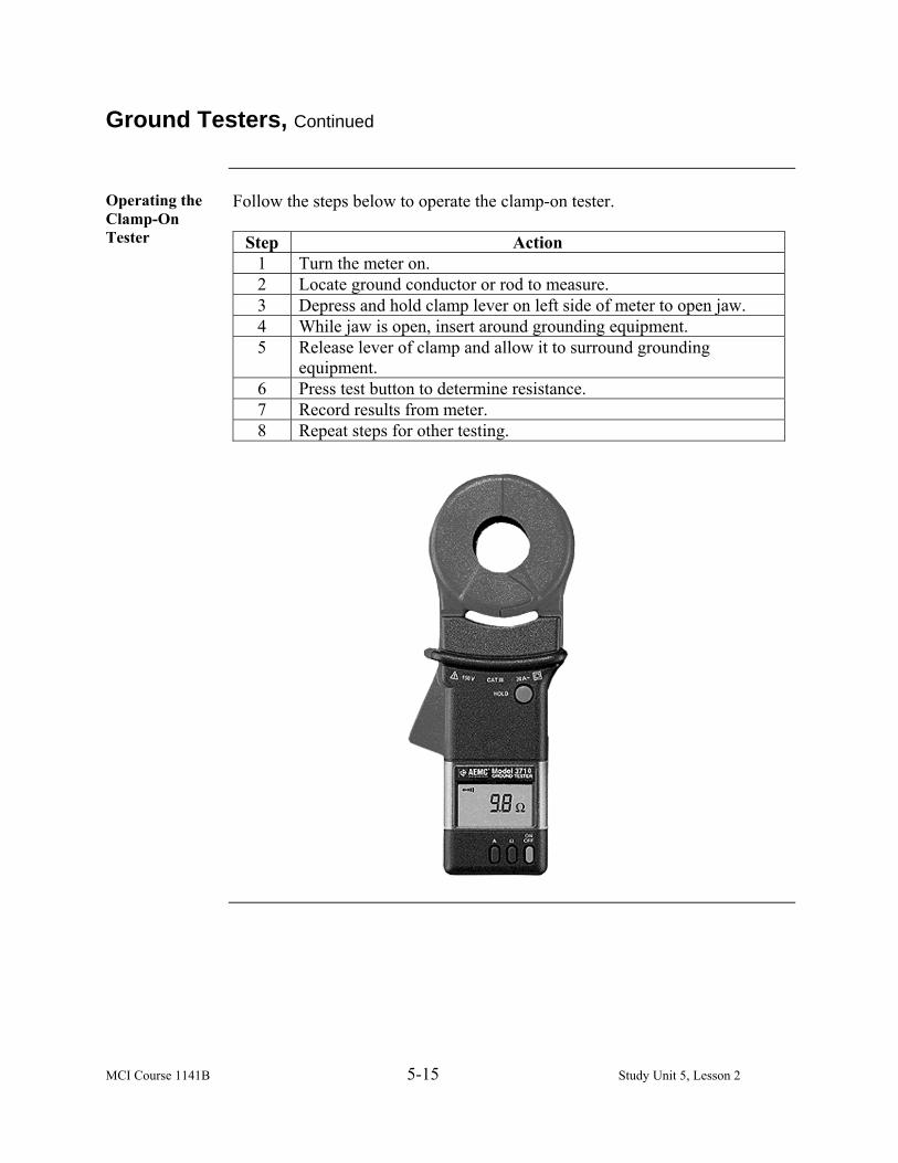
MCI Course 1141B 5-15 Study Unit 5, Lesson 2
Ground Testers, Continued
Operating the Clamp-On Tester
Follow the steps below to operate the clamp-on tester.
Step Action 1 Turn the meter on. 2 Locate ground conductor or rod to measure. 3 Depress and hold clamp lever on left side of meter to open jaw. 4 While jaw is open, insert around grounding equipment. 5 Release lever of clamp and allow it to surround grounding
equipment. 6 Press test button to determine resistance. 7 Record results from meter. 8 Repeat steps for other testing.

MCI Course 1141B 5-16 Study Unit 5, Lesson 2
(This page intentionally left blank.)

MCI Course 1141B 5-17 Study Unit 5, Lesson 2 Exercise
Lesson 2 Exercise
Directions Complete exercise items 1 through 6 by performing the action required.
Check your answers against those listed at the end of this lesson.
Item 1 A ______________ is an electronic measuring instrument that combines
several functions in one unit. a. ground tester b. digital multimeter c. potential probe d. clamp-on tester
Item 2 A digital multimeter is used for basic faultfinding and field ___________
work to troubleshoot electrical problems in a wide array of industrial and household devices. a. service b. house c. ground d. field service
Item 3 To operate the digital multimeter, insert the ________ test lead into the
multimeter under the _______ test connector. a. red; black b. black; black c. yellow; red d. yellow; black
Item 4 The purpose of the _________ is to determine the effectiveness of the
grounding medium with respect to true earth. a. digital multimeter b. clamp-on tester c. ground multimeter d. electrical ground tester
Continued on next page

MCI Course 1141B 5-18 Study Unit 5, Lesson 2 Exercise
Lesson 2 Exercise, Continued
Item 5 The two types of ground testers are _________ and clamp-on tester.
a. current probe b. potential probe c. fall-of-potential d. ground probe
Item 6 Which type of ground tester has two small ground rods, often referred to as
ground spikes or probes about 16 inches long? a. Fall-of-potential b. Potential probe c. Current probe d. Clamp-on tester
Continued on next page

MCI Course 1141B 5-19 Study Unit 5, Lesson 2 Exercise
Lesson 2 Exercise, Continued
Answers The table below lists the answers to the exercise items. If you have any
questions about these items, refer to the reference page.
Item Number Answer Reference 1 b 5-10 2 a 5-10 3 b 5-12 4 d 5-13 5 c 5-13 6 a 5-14

MCI Course 1141B 5-20 Study Unit 5, Lesson 2 Exercise
(This page intentionally left blank.)

MCI Course 1141B A-1 Appendix A
APPENDIX A
WORLD ELECTRIC GUIDE
Region
Type(s) of
Plug/Socket
Voltage Frequency Comments
Afghanistan C, D, F 240 V 50 Hz Voltage may vary from 160 to 280. Albania C, F 220 V 50 Hz Algeria C, F 230 V 50 Hz American Samoa A, B, F, I 120 V 60 Hz Andorra C, F 220 V 50 Hz Angola C 220 V 50 Hz Anguilla A (maybe B) 110 V 60 Hz Antigua A, B 230 V 60 Hz Airport power is reportedly 110 V.
Argentina C, I 220 V 50 Hz Live and neutral are reversed for socket outlet type I in comparison to most other countries.
Armenia C, F 220 V 50 Hz Aruba A, B, F 127 V 60 Hz Lago Colony 115 V.
Australia I 230 V 50 Hz
As of the year 2000, the main supply voltage as specified in AS 60038 has changed to 230 V with an allowed tolerance of +10% -6%. This was done in the interests of voltage harmonization; however, 240 V is within tolerance and is commonly found. Mains voltage is still popularly referred to as being “two-forty volts”.
Austria C, F 230 V 50 Hz Azerbaijan C 220 V 50 Hz
Azores B, C, F 220 V 50 Hz Ponta Delgada 110 V; to be converted to 220 V.
Bahamas A, B 120 V 60 Hz Along with 50 Hz in some outlying areas.
Bahrain G 230 V 50 Hz Awali 110 V, 60 Hz. Balearic Islands C, F 220 V 50 Hz

MCI Course 1141B A-2 Appendix A
Region
Type(s) of
Plug/Socket
Voltage Frequency Comments
Bangladesh A, C, D, G, K 220 V 50 Hz Barbados A, B 115 V 50 Hz Belarus C 220 V 50 Hz Belgium C, E 230 V 50 Hz
Belize A, B, G 110 V
and 220 V
60 Hz
Benin C, E 220 V 50 Hz Bermuda A, B 120 V 60 Hz Bhutan D, F, G, M 230 V 50 Hz Bolivia A, C 220 V 50 Hz La Paz and Viacha 115 V. Bosnia C, F 220 V 50 Hz Botswana D, G, M 231 V 50 Hz
Brazil A, B, C, I 110 V
and 220 V
60 Hz
Type I is becoming common for 220 V outlets and appliances in 110 V areas. Dual-voltage wiring is rather common in Brazil -- high-powered appliances, such as clothes dryers and electric showers, tend to be 220 V even in 110 V areas. Note also that depending on the area, the exact voltage might be 110 V, 115 V, 127 V, 130 V, 220 V or 240 V. The A, B, and C types are sometimes together (flat with rounder ends and ground pin) so that an A, B, or C types can be used. Also note that by 2009, Brazil will be converting to the IEC 60906-1 international plug, which is similar to type J.
Brunei G 240 V 50 Hz Bulgaria C, F 220 V 50 Hz Burkina Faso C, E 220 V 50 Hz Burundi C, E 220 V 50 Hz Cambodia A, C, G 230 V 50 Hz Cameroon C, E 220 V 50 Hz

MCI Course 1141B A-3 Appendix A
Region
Type(s) of
Plug/Socket
Voltage Frequency Comments
Canada A, B 120 V 60 Hz
Standardized at 120 V. 240 V/60 Hz used for heavy-duty applications (e.g., clothes driers, electric cook-stoves and machinery). Buildings with more than one branch circuit will have both voltages but 120 V is the norm in single voltage installations. Type A outlets used for retrofit only, and type B now required by regulations in new construction and renovation. A variant 20-amp, similar to type B, but with a T-slot, is used in kitchens in new construction.
Canary Islands C, E, L 220 V 50 Hz Cape Verde C, F 220 V 50 Hz Cayman Islands A, B 120 V 60 Hz Central African Republic C, E 220 V 50 Hz
Chad D, E, F 220 V 50 Hz Channel Islands C, G 230 V 50 Hz Chile C, L 220 V 50 Hz
China (mainland only) A, C, I 220 V 50 Hz
Most wall outlets simultaneously support types A, C, and I. Some outlets support both type A and type C (the holes in the outlets are flat in the middle and round on the sides) so that either a type A or a type C plug can be used. The type I outlet is next to the type A and C outlet. Type A outlets only fit plugs with pins of the same width -- a polarized type A plug requires an adapter. Note: No matter the type of plug the
socket will accept, voltage in China is always 220 volts.

MCI Course 1141B A-4 Appendix A
Region
Type(s) of
Plug/Socket
Voltage Frequency Comments
Colombia A, B 120 V 60 Hz
High-power air conditioners, restaurant equipment, cookstoves and ovens use 240-volt supplies. Wiring conventions, practices, and standards follow the Colombian Electrical Code (Codigo Electrico Colombiano), which is essentially a translation of the USA National Electric Code.
Comoros C, E 220 V 50 Hz Congo-Brazzaville C, E 230 V 50 Hz Congo-Kinshasa C, D 220 V 50 Hz Cook Islands I 240 V 50 Hz Costa Rica A, B 120 V 60 Hz Côte d'Ivoire C, E 230 V 50 Hz Croatia C, F 230 V 50 Hz Cuba A, B 110 V 60 Hz Cyprus G 240 V 50 Hz Czech Republic C, E 230 V 50 Hz Denmark C, K 230 V 50 Hz Type E is added from July 2008. Djibouti C, E 220 V 50 Hz Dominica D, G 230 V 50 Hz Dominican Republic A, B 110 V 60 Hz East Timor C, E, F, I 220 V 50 Hz Ecuador A, B 120 V 60 Hz Egypt C 220 V 50 Hz El Salvador A, B 115 V 60 Hz Equatorial Guinea C, E 220 V 50 Hz Eritrea C 230 V 50 Hz Estonia C, F 230 V 50 Hz Ethiopia C, E, F, L 220 V 50 Hz Faroe Islands C, K 220 V 50 Hz Falkland Islands G 240 V 50 Hz Fiji I 240 V 50 Hz Finland C, F 230 V 50 Hz
France C, E 230 V
(formerly 220 V)
50 Hz

MCI Course 1141B A-5 Appendix A
Region
Type(s) of
Plug/Socket
Voltage Frequency Comments
French Guiana C, D, E 220 V 50 Hz Gaza Strip C, H, M 230 V 50 Hz (see Israel) Gabon C 220 V 50 Hz Gambia G 230 V 50 Hz
Germany C, F 230 V
(formerly 220 V)
50 Hz
Type F (“Schuko”, short for “Schutzkontakt”) is standard. Type C plugs (“Euro-Stecker”) are common, especially for low-power devices. Type C wall sockets are very uncommon, and exist only in very old installations.
Ghana D, G 230 V 50 Hz
Gibraltar G, K 240 V 50 Hz
Type K was used in the Europort development by the Danish builders. Otherwise, the United Kingdom fittings are used.
Greece C, F 230 V
(formerly 220 V)
50 Hz
Type F is the de-facto standard for new installations’ sockets. Type C sockets exist only in old installations. Light appliances use type C plug while more electricity -- consuming ones use type E and F or F plugs.
Greenland C, K 220 V 50 Hz Grenada G 230 V 50 Hz Guadeloupe C, D, E 230 V 50 Hz Guam A, B 110 V 60 Hz Guatemala A, B 120 V 60 Hz Guinea C, F, K 220 V 50 Hz Guinea-Bissau C 220 V 50 Hz Guyana A, B, D, G 240 V 60 Hz Haiti A, B 110 V 60 Hz Honduras A, B 110 V 60 Hz

MCI Course 1141B A-6 Appendix A
Region
Type(s) of
Plug/Socket
Voltage Frequency Comments
Hong Kong S.A.R. of China
G, while D and M are used in old installations. M is still official when required current rating is between 13~15A.
220 V 50 Hz
Largely based on UK system. A ‘shaver’ socket (similar to type C) is sometimes found in bathrooms that will provide low current to some other plug types. These usually have a 110 V socket and a 220 V socket in the same unit, or a switch to select voltage, which are sometimes labeled as 110 V and 220 V. Not as common in Hong Kong as in the United Kingdom.
Hungary C, F 230 V 50 Hz Iceland C, F 230 V 50 Hz India C, D, M 230 V 50 Hz
Indonesia C, F, G 127 V
and 230 V
50 Hz Type G socket/plug is less common.
Iran C, F 220 V 50 Hz
Type C wall sockets are less common, and exist only in older installations. Type F is used for new installations. Type C plugs are common for low-power devices.
Iraq C, D, G 230 V 50 Hz

MCI Course 1141B A-7 Appendix A
Region
Type(s) of
Plug/Socket
Voltage Frequency Comments
Ireland
G found in all normal installations -- Legacy systems (rare/extinct): (D and M (as in the UK); and type F (Schuko))
230 V (formerly
220 V) 50 Hz
G sockets and plugs standard is defined by NSAI I.S. 401 (Plug) I.S. 411 (Socket outlet). Type F (“Side Earth”) plugs occasionally seen in old installations probably because much of the early Irish electrical network was heavily influenced by Siemens. A ‘shaver’ socket (similar to type C) is sometimes found in bathrooms that will provide low current to some other plug types. These usually have a 110 V socket and a 230 V socket in the same unit, or a switch to select voltage, which are sometimes labeled as 115 V and 230 V. The G type socket often has an on-off switch on the socket. The 110 V centre point earthed transformers are often used for industrial portable tools.
Isle of Man C, G 240 V 50 Hz
Israel C, H, M 230 V 50 Hz
Most modern sockets accept both type C and type H plugs. Type M sockets are used for air conditioners. Identical plugs and sockets also used in Israel (including the Palestinian National Authority areas).
Italy C, F, L 230 V
(formerly 220 V)
50 Hz Contracts of the “Enel” company reports a voltage of 220 V ±10%.
Jamaica A, B 110 V 50 Hz

MCI Course 1141B A-8 Appendix A
Region
Type(s) of
Plug/Socket
Voltage Frequency Comments
Japan A, B 100 V 50 Hz and
60 Hz
Eastern Japan 50 Hz (Tokyo, Kawasaki, Sapporo, Yokohama, and Sendai); Western Japan 60 Hz (Okinawa, Osaka, Kyoto, Kobe, Nagoya, and Hiroshima). Older buildings have nonpolarized sockets, in which case American polarized plugs (one prong wider than the other) would not fit. Many buildings do not have the ground pin. Sockets and switches fit in American-sized standard boxes.
Jordan B, C, D, F, G, J 230 V 50 Hz Kenya G 240 V 50 Hz
Kazakhstan C, E, F 220 V 50 Hz
No official standard. Voltage tolerance is 220 V ±10%. Actual voltage may vary (usually 150- 200 V) because of the energy crisys.
Kiribati I 240 V 50 Hz Korea, North C 220 V 50 Hz
Korea, South
A, B, C, F (Types A and B are used for 110-volt installations and/or found in very old buildings. Types C and F are used for 220 volts.)
220 V 60 Hz
Type F is found in offices, airports, hotels and some upscale homes, while type C (type CEE 7/17) is the norm in most households. The 220 volt power is distributed by using both “live” poles of a 110 volt system (neutral is not used). The 110 V/60 Hz power with plugs A and B (under Japanese colonial influence) was previously used, but has already been phased out. Some residents install their own step-down transformers and dedicated circuits, so that they can use 110 V appliances imported from Japan or North America. Most hotels only have 220 V outlets, but some hotels offer both 110 V (type A or B) and 220 V (type C or F) outlets. Switches and outlets fit American-sized boxes.

MCI Course 1141B A-9 Appendix A
Region
Type(s) of
Plug/Socket
Voltage Frequency Comments
Kuwait C, G 240 V 50 Hz Kyrgyzstan C Laos A, B, C, E, F 230 V 50 Hz Latvia C, F 220 V 50 Hz
Lebanon A, B, C, D, G 110 and
200 V 50 Hz
Lesotho M 220 V 50 Hz
Liberia A, B, C, E, F 120/240 V 50 Hz
Previously 60Hz, now officially 50Hz. Many private power plants are still 60 Hz. Types A and B are used for 110 V; and types C and F are used for 230/240 V. It is highly recommended to verify the voltage with a tester before plugging appliances in, no matter the outlet! (There has been no centralized power company in Liberia since the war began in 1990. All electricity is privately generated.)
Libya D, L 127 V 50 Hz Barce, Benghazi, Derna, Sebha, and Tobruk 230 V.
Lithuania C, F 230 V
(formerly 220 V)
50 Hz
Liechtenstein C, J 230 V 50 Hz Swiss Norm, type C only in the form CEE 7/16.
Luxembourg C, F 230 V
(formerly 220 V)
50 Hz
Macau S.A.R. of China
D, M, G, a small number of F 220 V 50 Hz
No official standards there. However, in the Macao-HK Ferry Pier built by Portuguese Government before handover the standard was E and F. After handover, Macau adopted type G in both government and private buildings.
Macedonia C, F 220 V 50 Hz
Madagascar C, D, E, J, K 127 V
and 220 V
50 Hz
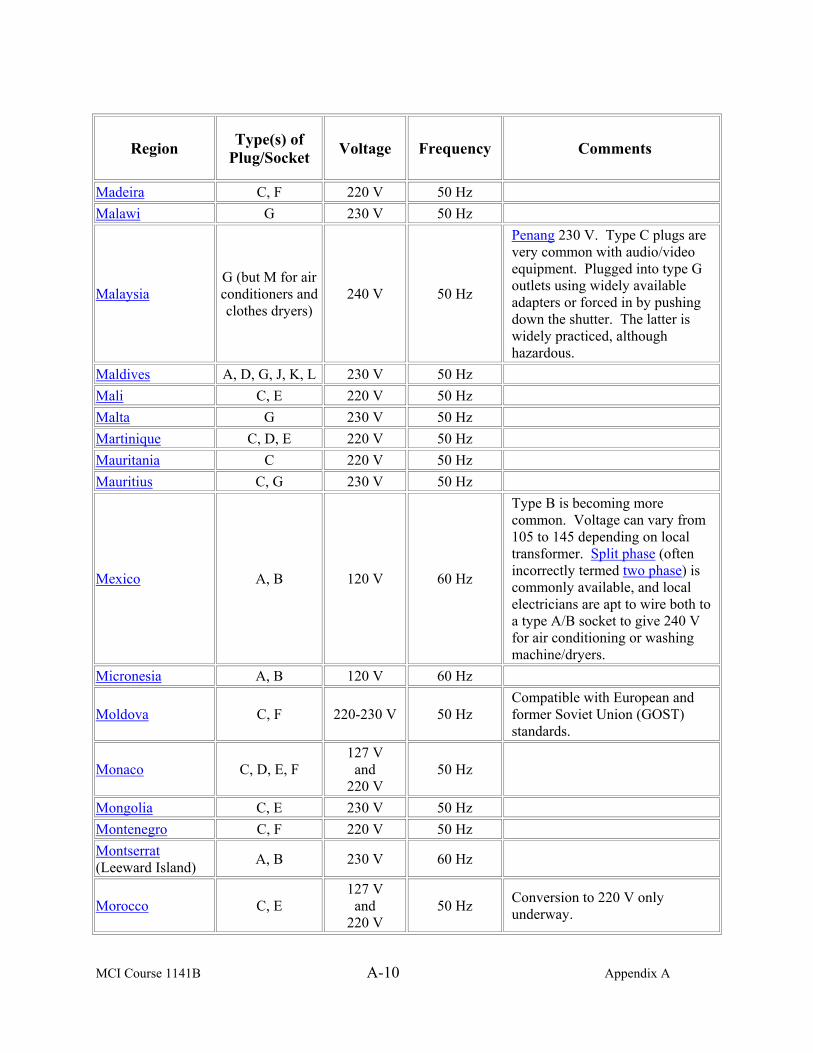
MCI Course 1141B A-10 Appendix A
Region
Type(s) of
Plug/Socket
Voltage Frequency Comments
Madeira C, F 220 V 50 Hz Malawi G 230 V 50 Hz
Malaysia G (but M for air conditioners and clothes dryers)
240 V 50 Hz
Penang 230 V. Type C plugs are very common with audio/video equipment. Plugged into type G outlets using widely available adapters or forced in by pushing down the shutter. The latter is widely practiced, although hazardous.
Maldives A, D, G, J, K, L 230 V 50 Hz Mali C, E 220 V 50 Hz Malta G 230 V 50 Hz Martinique C, D, E 220 V 50 Hz Mauritania C 220 V 50 Hz Mauritius C, G 230 V 50 Hz
Mexico A, B 120 V 60 Hz
Type B is becoming more common. Voltage can vary from 105 to 145 depending on local transformer. Split phase (often incorrectly termed two phase) is commonly available, and local electricians are apt to wire both to a type A/B socket to give 240 V for air conditioning or washing machine/dryers.
Micronesia A, B 120 V 60 Hz
Moldova C, F 220-230 V 50 Hz Compatible with European and former Soviet Union (GOST) standards.
Monaco C, D, E, F 127 V
and 220 V
50 Hz
Mongolia C, E 230 V 50 Hz Montenegro C, F 220 V 50 Hz Montserrat (Leeward Island) A, B 230 V 60 Hz
Morocco C, E 127 V
and 220 V
50 Hz Conversion to 220 V only underway.

MCI Course 1141B A-11 Appendix A
Region
Type(s) of
Plugs/Sockets
Voltage Frequency Comments
Mozambique C, F, M 220 V 50 Hz Type M found especially near the border with South Africa, including in the capital, Maputo.
Myanmar/Burma C, D, F, G 230 V 50 Hz
Type G found primarily in better hotels. Also, many major hotels chains are said to have outlets that will take type I plugs and perhaps other types.
Namibia D, M 220 V 50 Hz Nauru I 240 V 50 Hz Nepal C, D, M 230 V 50 Hz
Netherlands C, F 230 V
(formerly 220 V)
50 Hz
Netherlands Antilles A, B, F
127 V and
220 V 50 Hz
St. Martin 120 V, 60 Hz; Saba and St. Eustatius 110 V, 60 Hz, A, maybe B.
New Caledonia F 220 V 50 Hz
New Zealand I 230 V 50 Hz Electricity Regulations 1997 states supply voltage is 230 V ±6%.
Nicaragua A, B 120 V 60 Hz Niger A, B, C, D, E, F 220 V 50 Hz Nigeria D, G 240 V 50 Hz
Norway C, F 230 V 50 Hz IT earthing system.
Okinawa A, B 100 V 60 Hz Military facilities 120 V. Oman C, G 240 V 50 Hz Voltage variations common.
Pakistan C, D 220 V 50 Hz But Karachi Electric Supply Corporation (KESC) output is 240 volts and 50 Hz.
Panama A, B 110 V 60 Hz Panama City 120 V. Papua New Guinea I 240 V 50 Hz Paraguay C 220 V 50 Hz Peru A, B, C 220 V 60 Hz Talara 110/220 V; Arequipa 50 Hz.
Philippines A, B 220 V 60 Hz
Most plugs and outlets are type A, but some are B. Sockets and switches are built to USA dimensions and fit USA sized wall boxes. Some areas have 110 V as in Baguio.

MCI Course 1141B A-12 Appendix A
Region
Type(s) of
Plug/Socket
Voltage Frequency Comments
Poland C, E 230 V 50 Hz Portugal C, F 220 V 50 Hz Puerto Rico A, B 120 V 60 Hz Qatar D, G 240 V 50 Hz Réunion E 220 V 50 Hz
Romania C, F 230 V
(formerly 220 V)
50 Hz
Virtually identical to German standards. Most household sockets still compatible with East European standards (4.0 mm pins).
Russian Federation C, F 220 V 50 Hz
The former USSR (along with much of Eastern Europe) uses type GOST sockets with 4.0 mm pins instead of the 4.8mm standard used by West European (Schuko) Plugs. Obsolete standard 127 V/50 Hz AC is used in some peripheral villages. Elsewhere it was replaced in 1970s by the 220 V standard. Industrial appliances use 3-phase 380 V AC supply.
Rwanda C, J 230 V 50 Hz St. Kitts and Nevis D, G 230 V 60 Hz St. Lucia (Winward Island) G 240 V 50 Hz
St. Vincent (Winward Island) A, C, E, G, I, K 230 V 50 Hz
Saudi Arabia A, B, F, G 127 V
and 220 V
60 Hz
Senegal C, D, E, K 230 V 50 Hz Serbia C, F 220 V 50 Hz Seychelles G 240 V 50 Hz Sierra Leone D, G 230 V 50 Hz
Singapore G (but M for air conditioners and clothes dryers)
230 V 50 Hz Types A and C are used for audio/video equipment and plug adapters are widely available.
Slovakia C, E 230 V 50 Hz
Slovenia C, F 230 V 50 Hz The 360 V is used for heavy-duty applications.

MCI Course 1141B A-13 Appendix A
Region
Type(s) of
Plug/Socket
Voltage Frequency Comments
Somalia C 220 V 50 Hz
South Africa M 220 V 50 Hz Grahamstown and Port Elizabeth 250 V; also found in King Williams Town.
Spain C, F 230 V
(formerly 220 V)
50 Hz
Sri Lanka D, M, G 230 V 50 Hz An increased use of type G in new houses/establishments; mainly in Colombo and high end hotels.
Sudan C, D 230 V 50 Hz Suriname C, F 127 V 60 Hz Swaziland M 230 V 50 Hz Sweden C, F 230 V 50 Hz Switzerland C, J 230 V 50 Hz Type C only in the form CEE 7/16.Syria C, E, L 220 V 50 Hz
Tahiti A, B, E 110 V
and 220 V
60 Hz
Taiwan A, B 110/220 V 60 Hz
Most outlets are type A. When an outlet is type B, the ground (earth) holes are usually not connected to anything. Most appliances have type A plugs, but some appliances have type B plugs. Sockets and switches are built to USA dimensions and fit USA sized wall boxes. Dedicated sockets provide 220 V for air-conditioning units.
Tajikistan C, I 220 V 50 Hz Tanzania D, G 230 V 50 Hz

MCI Course 1141B A-14 Appendix A
Region
Type(s) of
Plug/Socket
Voltage Frequency Comments
Thailand A, B, C 220 V 50 Hz
Outlets in hotels and newer buildings are usually a combination of types B and C, which can accept plug types A, B, and C. Outlets in older buildings are usually type A. An equal proportion of appliances have type A or C plugs, or B if it requires an Earth connection. Type F is also in wide use, but is mainly used with high-powered appliances such as air conditioners, teakettles, and rice cookers. Types A, B, and combination B/C sockets are designed to fit USA/Japanese sized wall boxes.
Togo C 220 V 50 Hz Lome 127 V. Tonga I 240 V 50 Hz Trinidad and Tobago A, B 115 V 60 Hz
Tunisia C, E 230 V 50 Hz Turkey C, F 230 V 50 Hz Turkmenistan B, F 220 V 50 Hz Uganda G 240 V 50 Hz Ukraine C, F 220 V 50 Hz United Arab Emirates C, D, G 220 V 50 Hz
United Kingdom
G (D and M seen in very old installs and specialist
applications)
230 V (formerly
240 V) 50 Hz
Voltage tolerance of 230 V +10%/−6% (216.2 V to 253 V), to be widened to 230 V ±10% (207 V to 253 V) in 2008. A ‘shaver’ socket (similar to type C) is sometimes found in bathrooms that will provide low current to some other plug types. These usually have a 110 V socket and a 230 V socket in the same unit, or a switch to select voltage, which are sometimes labeled as 115 V and 230 V. The G type socket often has an on-off switch on the socket. The 110 V centre point earthed transformers are often used for industrial portable tools.

MCI Course 1141B A-15 Appendix A
Region
Type(s) of
Plug/Socket
Voltage Frequency Comments
United States of America A, B 120 V 60 Hz
Standardized at 120 V. Electricity suppliers aim to keep most customers supplied between 114 and 126 V most of the time. The 240 V/60 Hz used for heavy-duty applications (e.g., air conditioners, clothes dryers, stoves, ovens, and water heaters). Buildings with more than two branch circuits will usually have both 120 and 240 V available. Type B outlets are now required by code in new construction and renovation. A T-slot type B is rated for 20 amperes for use in kitchens or other areas using large 120 V appliances.
Uruguay C, F, I, L 230 V
(formerly 220 V)
50 Hz
Type F becoming more common because of computer use. Neutral and live wires are reversed, as in Argentina.
Uzbekistan C, I 220 V 50 Hz
Venezuela A, B 120 V 60 Hz Type G found in household 220 V service only for air conditioning and some high power appliances.
Vietnam A, C 220 V 50 Hz
Type A is the norm in Southern Vietnam and type C is the norm in Northern Vietnam (according to the pre-unification border at 17 degrees North). Type G is found only in some new luxury hotels, primarily those built by Singaporean and Hong Kong developers. However, type G is never found in homes, shops, or offices.
Virgin Islands A, B 110 V 60 Hz Western Samoa I 230 V 50 Hz Yemen A, D, G 230 V 50 Hz Zambia C, D, G 230 V 50 Hz Zimbabwe D, G 220 V 50 Hz

MCI Course 1141B A-16 Appendix A
(This page intentionally left blank.)
MCI Course 1141B B-1 Appendix B
APPENDIX B
OSHA’S ELECTRICAL STANDARDS
Safety Needs This page highlights OSHA standards, the Regulatory Agenda (a list of actions
being taken with regard to OSHA standards), Federal Registers (rules, proposed rules, and notices), directives (instructions for compliance officers), standard interpretations (official letters of interpretation of the standards), and national consensus standards related to electrical hazards. Highlighted Standards
General Industry (29 CFR 1910)
• 1910 Subpart I, Personal protective equipment [related topic page] • 1910.137, Electrical protective devices
• 1910 Subpart R, Special industries
• 1910.269, Electric power generation, transmission, and distribution [related topic page]
• 1910 Subpart S, Electrical
• 1910.302, Electric utilization systems • 1910.303, General requirements • 1910.304, Wiring design and protection • 1910.305, Wiring methods, components, and equipment for
general use • 1910.306, Specific purpose equipment and installations • 1910.307, Hazardous (classified) locations • 1910.308, Special systems • 1910.331, Scope • 1910.332, Training • 1910.333, Selection and use of work practices • 1910.334, Use of equipment • 1910.335, Safeguards for personnel protection
Shipyard Employment (29 CFR 1915)
• 1915 Subpart L, Electrical machinery • 1915.181, Electrical circuits and distribution boards
Continued on next page
MCI Course 1141B B-2 Appendix B
Safety Needs, continued
Marine Terminals (29 CFR 1917)
• 1917 Subpart G, Related terminal operations and equipment • 1917.157, Battery charging and changing
Regulatory Agenda
• The OSHA Regulatory Agenda contains an entry related to electrical standards.
Federal Registers
• Electrical Standard; Final Rule. Final Rules 72:7135-7221, (2007, February 14). Focuses on safety in the design and installation of electric equipment in the workplace. This revision provides the first update of the installation requirements in the general industry electrical installation standard since 1981.
• Electrical Standard; Proposed Rule. Proposed Rules 69:17773-17842, (2004, April 5). OSHA proposes to revise the general industry electrical installation standard found in 29 CFR 1910, Subpart S.
• Search all available Federal Registers.
Directives
• Enforcement of the Electrical Power Generation, Transmission, and Distribution Standard. CPL 02-01-038 [CPL 2-1.38], (2003, June 18). Provides information to assist compliance personnel in performing inspections in electric power generation, transmission, and installations, including that of distribution lines and other equipment.
• OSHA Technical Manual (OTM). TED 01-00-015 [TED 1-0.15A], (1999, January 20). Assists OSHA Compliance Safety and Health Officers (CSHOs) in hazard recognition and provides guidance in accident prevention. Serves as a source of advice for CSHOs on safety and health issues.
• Inspection Guidelines for 29 CFR 1910. Subpart I, the revised Personal Protective Equipment Standards for General Industry. STD 01-06-006 [STD 1-6.6], (1995, June 16). Provides inspection assistance which addresses the revised personal protective equipment (PPE) standards, (29 CFR 1910, Subpart I), to assist OSHA Compliance Safety and Health Officers (CSHOs) performing inspections in general industry.
Continued on next page

MCI Course 1141B B-3 Appendix B
Safety Needs, continued
• Electrical Safety-Related Work Practices -- Inspection Procedures and Interpretation Guidelines. STD 01-16-007 [STD 1-16.7], (1991, July 1). Establishes policies and provides interpretive guidelines to ensure uniform enforcement of the standard for electrical safety-related work practices, 29 CFR 1910.331 through 1910.335.
• Search all available directives.
Standard Interpretations
• Training requirements for employees who perform non-electrical work on electrical equipment. (2002, May 17).
• Qualifications for resetting circuits or replacing fuses; electrical enclosures must be approved. (2001, November 19).
• Search all available standard interpretations.
National Consensus
Note: These are NOT OSHA regulations. However, they do provide guidance from their originating organizations related to worker protection. National Fire Protection Association (NFPA) 70, National Electric Code, (2008).

MCI Course 1141B B-4 Appendix B
(This page intentionally left blank.)
MCI Course 1141B R-1 Review Lesson Examination
MARINE ELECTRICIAN
REVIEW LESSON EXAMINATION
Review Lesson
Introduction The purpose of the review lesson examination is to prepare you for your final
examination. We recommend that you try to complete your review lesson examination without referring to the text, but for those Items (question) you are unsure of, restudy the test. When you finish your review lesson and are satisfied with your response, check your responses against the answers provided at the end of this review lesson examination.
Directions Select the ONE answer that BEST completes the statement or that answers
the Item. For multiple choice Items, circle your response. For matching Items, place the letter of your response in the space provided.
Item 1 The force that moves electrons is the definition of
a. amps. b. current c. electricity. d. ohms.
Item 2 What is the most important aspect of the atom in regards to electricity?
a. Protons b. Neutrons c. Molecules d. Electrons
Continued on next page
MCI Course 1141B R-2 Review Lesson Examination
Review Lesson, Continued
Item 3 When converting electrical energy to kinetic, what is the unit of measure?
a. Amp b. Atom c. Volt d. Watt
Item 4 Which of the following is the mathematical equation that represents Ohm’s
Law? a. I = E x R b. E = I x R c. R = I x E d. R = E x I
Item 5 A scalar physical quantity used to describe change is defined as
a. power. b. energy. c. watt. d. circuit.
Item 6 The main types of mechanical energy are _______ and potential.
a. thermal b. kinetic c. chemical d. energy
Item 7 Which equation represents power?
a. P = E x R b. P = E x I c. P = I x R d. P = V x R
Continued on next page

MCI Course 1141B R-3 Review Lesson Examination
Review Lesson, Continued
Item 8 A space heater has a 30-ohm of resistance connected to a voltage source of
120 volts. What is the amount of power converted to heat? a. P = 480 watts b. P = 240 watts c. P = 360 watts d. P = 500 watts
Item 9 What is the metric prefix, mega, numerically equivalent to?
a. .000,000,001 b. .000,001 c. 1,000,000,000,000 d. 1,000,000
Item 10 When any number of devices is connected so that there is only a single circuit
path for electrons to flow, what type of circuit is it? a. Series b. Parallel c. Series-parallel d. Magnetic
Item 11 In a series circuit, you have an amperage of 10 at the first receptacle and an
amperage of 10 at the second receptacle, how many total amps are there in this circuit? a. 5 b. 10 c. 20 d. 40
Continued on next page

MCI Course 1141B R-4 Review Lesson Examination
Review Lesson, Continued
Item 12 A series circuit has 120 volts entering the circuit to provide power to six
lights. If the lights are all the same and they have the same resistance, what is the voltage drop at each light? a. 20 volts b. 10 volts c. 60 volts d. 120 volts
Item 13 A ________ circuit is when any number of devices is connected so that there
is more than one circuit path for electrons to flow. a. parallel b. magnetic c. series-parallel d. series
Item 14 What is the total resistance of a parallel circuit when the resistance of three
circuits is 10 ohms, 20 ohms, and 15 ohms? a. 30 ohms b. 4.01 ohms c. 4.61 ohms d. 5.35 ohms
Item 15 Never operate generator sets without proper ___________ protection.
a. eye b. chest c. face d. hearing
Continued on next page

MCI Course 1141B R-5 Review Lesson Examination
Review Lesson, Continued
Item 16 The ORM five-step process is used to identify hazards, assess hazards to
determine risk, develop control and make risk decisions, ___________, and supervise and evaluate. a. manage risk b. implement risk control c. develop tactics d. operate management
Item 17 Which category results in the hazard causing death, loss of facility/asset, or
result in grave damage to national interests? a. Category I b. Category II c. Category III d. Category IV
Item 18 What class of fire extinguisher includes flammable liquids such as oil or
gasoline filled with a foam carbon tetrachloride or carbon dioxide, dry compound, or sand? a. Class A b. Class B c. Class C d. Class ABC
Item 19 Tag-out must be placed on an energy isolating device that indicates the
equipment being controlled is not operated until the tag-out is a. replaced. b. removed. c. found. d. changed.
Continued on next page

MCI Course 1141B R-6 Review Lesson Examination
Review Lesson, Continued
Item 20 Tissue heating due to resistance can cause which type of electrical shock
effect? a. Psychological b. Burns c. Neurological d. Ventricular fibrillation
Item 21 In helping a casualty of electrical shock, what is the first thing you do?
a. Disconnect the power supply. b. Roll him over. c. Call his name. d. Pull him from the location.
Item 22 When checking the breathing of an electrical shock casualty, what is the first
step? a. Determine if the casualty is breathing. b. Clear the airway. c. Check for fractures. d. Ventilate the casualty
Item 23 What is the first thing you do when conducting a pole top rescue?
a. Call for help. b. Climb the pole to rescue the casualty. c. Evaluate the situation. d. Notify the commanding officer and inform him of the situation.
Item 24 The three most traditional types of renewable energy sources are
a. solar, water, and wind. b. solar, water, and wave. c. nuclear, water, and wind. d. nuclear, water, and wave.
Continued on next page

MCI Course 1141B R-7 Review Lesson Examination
Review Lesson, Continued
Item 25 Which non-renewable energy source is the fastest growing energy source in
the world producing electricity? a. Coal b. Natural Gas c. Oil d. Nuclear
Item 26 What is the measure of a material’s ability to conduct an electric current?
a. Voltage b. Conductance c. Current d. Resistance
Item 27 Silver, copper, and __________ are good conductors.
a. aluminum b. wood c. rubber d. gold
Item 28 The four factors that determine resistance in a conductor are cross sectional
area, length, temperature, and a. type of material. b. weather. c. amperage. d. voltage.
Continued on next page

MCI Course 1141B R-8 Review Lesson Examination
Review Lesson, Continued
Item 29 A measure of the degree to which an object opposes electric current through it
is defined as what? a. Resistance b. Voltage c. Current d. Conductance
Item 30 The materials that would make good conductors are iron, _________, and
silver. a. glass b. nichrome c. nylon d. rubber
Item 31 What is the resistance of an aluminum wire that has an ohms resistance of 17
per mil foot, 10400 area in circular mils, and a length of 100 feet? a. .16 ohms b. .001 ohms c. .016 ohms d. 16 ohms
Item 32 The __________________ chart is a standardized wire gauge system used in
the United States and other countries. a. American Wire Gauge b. American Brown Wire Gauge c. American Standard Wire Gauge d. American Standard Gauge
Continued on next page

MCI Course 1141B R-9 Review Lesson Examination
Review Lesson, Continued
Item 33 Stranded wire may be classified into three types: bunch, _________, and
rope. a. concentric b. wire c. coiled d. round
Item 34 One of the methods to strip wire from its protective sheathing is the
a. combination tool. b. screwdriver. c. pliers. d. hammer.
Item 35 What is the importance of a third pin outlet?
a. Prevent electrocution b. Keep the fuse from blowing c. Prevent burning of your hands d. Prevent death
Item 36 Which connector is similar to type C except it is round and has the addition of
two grounding clips on the side of the plug? a. Type A b. Type F c. Type G d. Type H
Continued on next page

MCI Course 1141B R-10 Review Lesson Examination
Review Lesson, Continued
Item 37 When connecting wires to screw terminals, what do you do first?
a. Tighten the screws firmly to ensure insulation does not touch the head of the screw. b. Perform lock out and tag out procedures. c. Attach black wires to the gold wires. d. Use a new strip of wire to connect to the gold wires.
Item 38 When connecting the wires to switch receptacles with push-in fittings, mark
the amount of insulation to be stripped from each wire using the __________ on the back of the switch or receptacle. a. strip gauge b. aluminum wires c. copper wires d. scratch awl
Item 39 The _______________ generator consists of a diesel engine, brushless
generator, excitation system, speed governing system, fuel system, and produces electricity at 400 hertz. a. TQG-805 b. TQG-813 c. QG-806 d. TQG-807
Item 40 Which generator has 30kW, 50/60 Hz?
a. Engine b. TQG-805 c. TQG-807 d. TQG-831A
Continued on next page

MCI Course 1141B R-11 Review Lesson Examination
Review Lesson, Continued
Item 41 Load cables are connected to a ___________ to provide electricity.
a. engine b. generator c. carburator d. wall
Item 42 Which is the second important factor when selecting a generator site?
a. Performance b. Terrain c. Safety d. Environment
Item 43 What is the maximum distance that fuel drums can be placed from the
generators for fueling purposes? a. 10 feet b. 25 feet c. 30 feet d. 100 feet
Item 44 Environmental protection equipment is used to keep fuel, oil, and radiator
coolant from contaminating the ground. The different types include fuel berms, drip pans, __________, and over pack drums. e. fuel pans f. plates g. quick berms h. caps
Continued on next page

MCI Course 1141B R-12 Review Lesson Examination
Review Lesson, Continued
Item 45 When an electrical system is connected to earth in a manner that will limit
lightning, line surges, or unintentional contact with higher voltage is defined as what? a. Over current protection b. Neutralizing c. Grounding d. Bonding
Item 46 The permanent joining of metallic parts to form an electrically conductive
path that ensures electrical continuity and the capacity to conduct safely any current likely to be imposed is called what? a. Shielding b. Neutralizing c. Grounding d. Bonding
Item 47 What type of grounding equipment is another method to conduct good
grounding? a. Donut trench b. Ground plate c. Existing facilities d. Basin trench
Item 48 When using the ________________ method to install a ground rod, use a
shovel and dig a hole 18-inches wide and 1-foot deep. a. doughnut trench b. basin trench c. grounding trench d. ground rod
Continued on next page

MCI Course 1141B R-13 Review Lesson Examination
Review Lesson, Continued
Item 49 What type of soil is the poorest type for grounding capabilities?
a. Gravel, sand, or stone b. Clay or shale mixed with gravel or sand c. Humus or fine soil granules with high moisture content d. Clay, loam, or shale
Item 50 Which distribution panel board has two three-phase 20-ampre breakers and
outputs, and nine single-phase 20-ampere breakers and outputs? a. 5 kW MEPDIS b. 5 kW MEPDIS-R c. 15 kW MEPDIS d. 15 kW MEPDIS-R
Item 51 Which of the following provides electrical power distribution through
electrical outlets, and illumination through incandescent lights and switches? a. Illumination set b. Field wiring harness set c. Distribution panel d. Distribution box
Item 52 Which cable provides illumination through the use of incandescent bulbs?
a. Wye connection cable b. Light cable c. Receptacle cable d. Commercial power jump cable
Item 53 The MEPDIS-R is composed of six power distribution boxes: 5 kW outdoor,
5 kW indoor, 30 kW, _______ kW, 100 kW, and 300 kW power distribution boxes. a. 15 b. 150 c. 20 d. 200
Continued on next page

MCI Course 1141B R-14 Review Lesson Examination
Review Lesson, Continued
Item 54 Which cable set features five-wire, three-phase, 100-amp pin and sleeve IEC
309 receptacles on output end and plug on input end, and is 50-feet long? a. #2 b. #4 c. #5 d. #6
Item 55 To install MEPDIS/MEPDIS-R into operation, switch the ___________
circuit breaker to the ______ position and monitor the phase indicator lights to verify that the electrical distribution panel is functioning properly. a. input; OFF b. output; ON c. output; OFF d. input; ON
Item 56 Having the nomenclature of the Item, what are the minimum requirements
located on the Inventory Sheet? a. National stock number or service number, amount, and quality b. National stock number or part number, unit of issue, and its quantity c. National stock number or service number, unit of issue, and quality d. National stock number or part number, amount, and quality
Item 57 Using an inventory sheet and conducting an inventory on MEPDIS, what
marking would you annotate for an item that is missing for a 100 kW panel? a. M b. R c. EM d. U
Continued on next page
MCI Course 1141B R-15 Review Lesson Examination
Review Lesson, Continued
Item 58 To setup the bus bar, place a grounding rod about _____ foot/feet from the
bus bar and drive it into the ground to the proper depth of 8 to 8 1/2 feet. a. 1/2 b. 2 c. 1 d. 3
Item 59 Which type of ground is applied to the neutral conductor and reduces the
possibility of fire and shock by reducing the voltage to zero volts? a. Metal b. System c. Circuit d. Equipment
Item 60 To connect a generator to a bus bar, run _____ conductors from the general
terminal board to the input connections of the switch box, which is mounted to the bus bar. a. four b. three c. five d. two
Item 61 The ________ tie is used for supporting the conductor when it is not feasible
to run the conductor through the insulator racks. a. front b. side c. corner d. dead end
Continued on next page

MCI Course 1141B R-16 Review Lesson Examination
Review Lesson, Continued
Item 62 What is a pigtail wire splice used for?
a. To support the conductor when support is needed at direction changes b. To make connections between two electric conductors c. To protect the over current d. To reduce the possibility of fire and shock
Item 63 The tools in the lineman’s tool kit are used to install, operate, and maintain heating equipment, mobile electric power generating sources, and electrical distribution systems, and repair telephone and _________ wire. a. line b. telegraph c. computer d. cable
Item 64 Check and clean tools that require ______________ or power to provide
maximum performance. a. calibration b. replacement c. preserving d. maintenance
Item 65 A __________ includes features such as the ability to measure voltage,
current, and resistance. a. digital multimeter b. ground tester c. potential probe d. clamp-on tester
Item 66 The digital multimeter is used for faultfinding and ___________ work.
a. house b. field service c. ground d. service
Continued on next page

MCI Course 1141B R-17 Review Lesson Examination
Review Lesson, Continued
Item 67 When performing operational checks and services, insert the _____ test into
the ______ testing lead connector. a. red; black b. red; red c. yellow; red d. black; yellow
Item 68 The purpose of the _________ is to determine the effectiveness of the
grounding medium with respect to true earth. a. electrical ground tester b. digital multi-meter c. clamp-on tester d. ground multi-meter
Item 69 Which type of ground tester has two small ground rods, often referred to as
ground spikes or probes about 16-inches long? a. Fall-of-potential b. Potential probe c. Current probe d. Clamp-on tester
Continued on next page
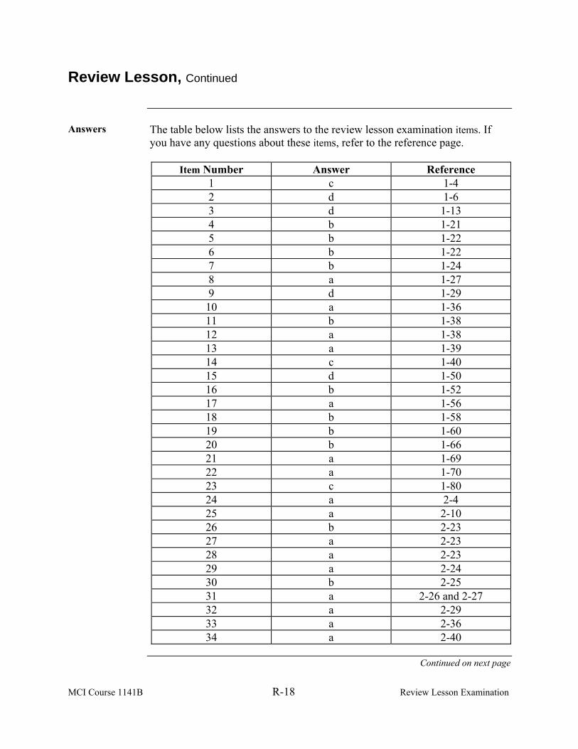
MCI Course 1141B R-18 Review Lesson Examination
Review Lesson, Continued
Answers The table below lists the answers to the review lesson examination items. If
you have any questions about these items, refer to the reference page.
Item Number Answer Reference 1 c 1-4 2 d 1-6 3 d 1-13 4 b 1-21 5 b 1-22 6 b 1-22 7 b 1-24 8 a 1-27 9 d 1-29 10 a 1-36 11 b 1-38 12 a 1-38 13 a 1-39 14 c 1-40 15 d 1-50 16 b 1-52 17 a 1-56 18 b 1-58 19 b 1-60 20 b 1-66 21 a 1-69 22 a 1-70 23 c 1-80 24 a 2-4 25 a 2-10 26 b 2-23 27 a 2-23 28 a 2-23 29 a 2-24 30 b 2-25 31 a 2-26 and 2-27 32 a 2-29 33 a 2-36 34 a 2-40
Continued on next page
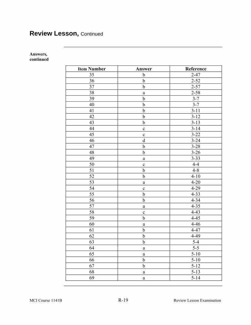
MCI Course 1141B R-19 Review Lesson Examination
Review Lesson, Continued
Answers, continued
Item Number Answer Reference 35 b 2-47 36 b 2-52 37 b 2-57 38 a 2-58 39 b 3-7 40 b 3-7 41 b 3-11 42 b 3-12 43 b 3-13 44 c 3-14 45 c 3-22 46 d 3-24 47 b 3-28 48 b 3-26 49 a 3-33 50 c 4-4 51 b 4-8 52 b 4-10 53 a 4-20 54 c 4-29 55 b 4-33 56 b 4-34 57 a 4-35 58 c 4-43 59 b 4-45 60 a 4-46 61 b 4-47 62 b 4-49 63 b 5-4 64 a 5-5 65 a 5-10 66 b 5-10 67 b 5-12 68 a 5-13 69 a 5-14

MCI Course 1141B R-20 Review Lesson Examination
(This page intentionally left blank.)