MARC70 Installation Manual - Sandia...
29
MARC70 Installation Manual SA 3/L/NVG SA 15 SA 24 305147-00 3700 Osuna Rd. NE, Suite 711 Albuquerque, NM 87109 505.341.2930 www.sandia.aero SR 34 SR 54 SR 64 SR 263 SR 342 SR 623 SRU 1 SRU 5 SRU 10
Transcript of MARC70 Installation Manual - Sandia...

MARC70Installation Manual
SA 3/L/NVGSA 15SA 24
305147-00
3700 Osuna Rd. NE, Suite 711Albuquerque, NM 87109505.341.2930www.sandia.aero
SR 34SR 54SR 64
SR 263SR 342SR 623
SRU 1SRU 5SRU 10
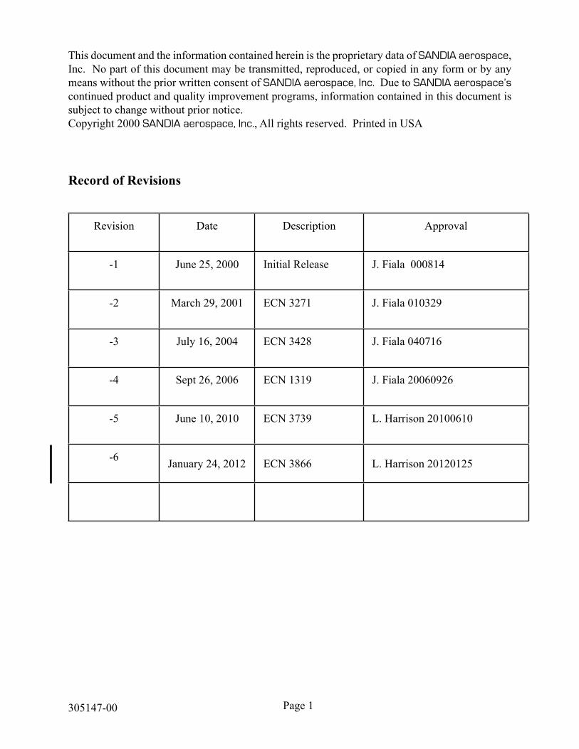
Record of Revisions
Revision Date Description Approval
-1 June 25, 2000 Initial Release J. Fiala 000814
-2 March 29, 2001 ECN 3271 J. Fiala 010329
-3 July 16, 2004 ECN 3428 J. Fiala 040716
-4 Sept 26, 2006 ECN 1319 J. Fiala 20060926
-5 June 10, 2010 ECN 3739 L. Harrison 20100610
-6 January 24, 2012 ECN 3866 L. Harrison 20120125
This document and the information contained herein is the proprietary data of SANDIA aerospace, Inc. No part of this document may be transmitted, reproduced, or copied in any form or by any means without the prior written consent of SANDIA aerospace, Inc. Due to SANDIA aerospace’s continued product and quality improvement programs, information contained in this document is subject to change without prior notice.Copyright 2000 SANDIA aerospace, Inc., All rights reserved. Printed in USA
Page 1305147-00
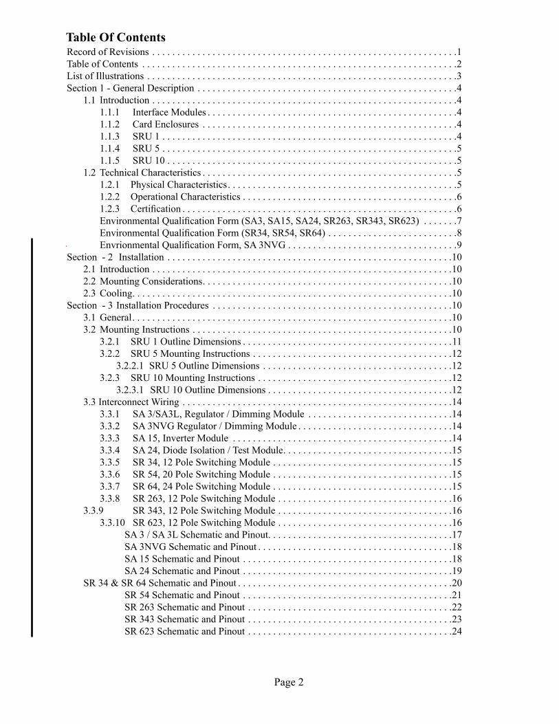
Table Of ContentsRecord of Revisions . . . . . . . . . . . . . . . . . . . . . . . . . . . . . . . . . . . . . . . . . . . . . . . . . . . . . . . . . . . . .1Table of Contents . . . . . . . . . . . . . . . . . . . . . . . . . . . . . . . . . . . . . . . . . . . . . . . . . . . . . . . . . . . . . . .2List of Illustrations . . . . . . . . . . . . . . . . . . . . . . . . . . . . . . . . . . . . . . . . . . . . . . . . . . . . . . . . . . . . . .3Section 1 - General Description . . . . . . . . . . . . . . . . . . . . . . . . . . . . . . . . . . . . . . . . . . . . . . . . . . . .4
1.1 Introduction . . . . . . . . . . . . . . . . . . . . . . . . . . . . . . . . . . . . . . . . . . . . . . . . . . . . . . . . . . . . .4 1.1.1 Interface Modules . . . . . . . . . . . . . . . . . . . . . . . . . . . . . . . . . . . . . . . . . . . . . . . . . .4 1.1.2 Card Enclosures . . . . . . . . . . . . . . . . . . . . . . . . . . . . . . . . . . . . . . . . . . . . . . . . . . .4 1.1.3 SRU 1 . . . . . . . . . . . . . . . . . . . . . . . . . . . . . . . . . . . . . . . . . . . . . . . . . . . . . . . . . . .4 1.1.4 SRU 5 . . . . . . . . . . . . . . . . . . . . . . . . . . . . . . . . . . . . . . . . . . . . . . . . . . . . . . . . . . .5 1.1.5 SRU 10 . . . . . . . . . . . . . . . . . . . . . . . . . . . . . . . . . . . . . . . . . . . . . . . . . . . . . . . . . .51.2 Technical Characteristics . . . . . . . . . . . . . . . . . . . . . . . . . . . . . . . . . . . . . . . . . . . . . . . . . . .5 1.2.1 Physical Characteristics . . . . . . . . . . . . . . . . . . . . . . . . . . . . . . . . . . . . . . . . . . . . . .5 1.2.2 Operational Characteristics . . . . . . . . . . . . . . . . . . . . . . . . . . . . . . . . . . . . . . . . . . .6 1.2.3 Certification . . . . . . . . . . . . . . . . . . . . . . . . . . . . . . . . . . . . . . . . . . . . . . . . . . . . . . .6 EnvironmentalQualificationForm(SA3,SA15,SA24,SR263,SR343,SR623) . . . . . . .7 EnvironmentalQualificationForm(SR34,SR54,SR64) . . . . . . . . . . . . . . . . . . . . . . . . . .8 EnvrionmentalQualificationForm,SA3NVG . . . . . . . . . . . . . . . . . . . . . . . . . . . . . . . . . .9
Section - 2 Installation . . . . . . . . . . . . . . . . . . . . . . . . . . . . . . . . . . . . . . . . . . . . . . . . . . . . . . . . .102.1 Introduction . . . . . . . . . . . . . . . . . . . . . . . . . . . . . . . . . . . . . . . . . . . . . . . . . . . . . . . . . . . .102.2 Mounting Considerations . . . . . . . . . . . . . . . . . . . . . . . . . . . . . . . . . . . . . . . . . . . . . . . . . .102.3 Cooling . . . . . . . . . . . . . . . . . . . . . . . . . . . . . . . . . . . . . . . . . . . . . . . . . . . . . . . . . . . . . . . .10
Section - 3 Installation Procedures . . . . . . . . . . . . . . . . . . . . . . . . . . . . . . . . . . . . . . . . . . . . . . . .103.1 General . . . . . . . . . . . . . . . . . . . . . . . . . . . . . . . . . . . . . . . . . . . . . . . . . . . . . . . . . . . . . . . .103.2 Mounting Instructions . . . . . . . . . . . . . . . . . . . . . . . . . . . . . . . . . . . . . . . . . . . . . . . . . . . .10 3.2.1 SRU 1 Outline Dimensions . . . . . . . . . . . . . . . . . . . . . . . . . . . . . . . . . . . . . . . . . .11 3.2.2 SRU 5 Mounting Instructions . . . . . . . . . . . . . . . . . . . . . . . . . . . . . . . . . . . . . . . .12 3.2.2.1 SRU 5 Outline Dimensions . . . . . . . . . . . . . . . . . . . . . . . . . . . . . . . . . . . . . .12 3.2.3 SRU 10 Mounting Instructions . . . . . . . . . . . . . . . . . . . . . . . . . . . . . . . . . . . . . . .12 3.2.3.1 SRU 10 Outline Dimensions . . . . . . . . . . . . . . . . . . . . . . . . . . . . . . . . . . . . .123.3 Interconnect Wiring . . . . . . . . . . . . . . . . . . . . . . . . . . . . . . . . . . . . . . . . . . . . . . . . . . . . . .14 3.3.1 SA 3/SA3L, Regulator / Dimming Module . . . . . . . . . . . . . . . . . . . . . . . . . . . . .14 3.3.2 SA3NVGRegulator/DimmingModule . . . . . . . . . . . . . . . . . . . . . . . . . . . . . . .14 3.3.3 SA 15, Inverter Module . . . . . . . . . . . . . . . . . . . . . . . . . . . . . . . . . . . . . . . . . . . .14 3.3.4 SA 24, Diode Isolation / Test Module . . . . . . . . . . . . . . . . . . . . . . . . . . . . . . . . . .15 3.3.5 SR 34, 12 Pole Switching Module . . . . . . . . . . . . . . . . . . . . . . . . . . . . . . . . . . . .15 3.3.6 SR 54, 20 Pole Switching Module . . . . . . . . . . . . . . . . . . . . . . . . . . . . . . . . . . . .15 3.3.7 SR 64, 24 Pole Switching Module . . . . . . . . . . . . . . . . . . . . . . . . . . . . . . . . . . . .15 3.3.8 SR 263, 12 Pole Switching Module . . . . . . . . . . . . . . . . . . . . . . . . . . . . . . . . . . .16 3.3.9 SR 343, 12 Pole Switching Module . . . . . . . . . . . . . . . . . . . . . . . . . . . . . . . . . . .16 3.3.10 SR 623, 12 Pole Switching Module . . . . . . . . . . . . . . . . . . . . . . . . . . . . . . . . . . .16 SA 3 / SA 3L Schematic and Pinout . . . . . . . . . . . . . . . . . . . . . . . . . . . . . . . . . . . . .17 SA3NVGSchematicandPinout . . . . . . . . . . . . . . . . . . . . . . . . . . . . . . . . . . . . . . .18 SA 15 Schematic and Pinout . . . . . . . . . . . . . . . . . . . . . . . . . . . . . . . . . . . . . . . . . .18 SA 24 Schematic and Pinout . . . . . . . . . . . . . . . . . . . . . . . . . . . . . . . . . . . . . . . . . .19 SR 34 & SR 64 Schematic and Pinout . . . . . . . . . . . . . . . . . . . . . . . . . . . . . . . . . . . . . . . . . . .20 SR 54 Schematic and Pinout . . . . . . . . . . . . . . . . . . . . . . . . . . . . . . . . . . . . . . . . . .21 SR 263 Schematic and Pinout . . . . . . . . . . . . . . . . . . . . . . . . . . . . . . . . . . . . . . . . .22 SR 343 Schematic and Pinout . . . . . . . . . . . . . . . . . . . . . . . . . . . . . . . . . . . . . . . . .23 SR 623 Schematic and Pinout . . . . . . . . . . . . . . . . . . . . . . . . . . . . . . . . . . . . . . . . .24
Page 2

List of Illustrations
Figure 3-1 SRU 1 Outline Dimensions . . . . . . . . . . . . . . . . . . . . . . . . . . . . . . . . . . . 11Figure 3-2 SRU 5 / SRU 5-01 Outline Dimensions . . . . . . . . . . . . . . . . . . . . . . . . . . 12Figure 3-3 SRU 10 Outline Dimension . . . . . . . . . . . . . . . . . . . . . . . . . . . . . . . . . . . 13Figure 3-4 SA 3 / SA 2L Schematic and Pinout . . . . . . . . . . . . . . . . . . . . . . . . . . . . . 17Figure3-5 SA3NVGSchematicandPinout . . . . . . . . . . . . . . . . . . . . . . . . . . . . . . . 18Figure 3-6 SA 15 Schematic and Pinout . . . . . . . . . . . . . . . . . . . . . . . . . . . . . . . . . . . 19Figure 3-7 SA 24 Schematic and Pinout . . . . . . . . . . . . . . . . . . . . . . . . . . . . . . . . . . . 20Figure 3-8 SR 34 and SR 64 Schematic and Pinout . . . . . . . . . . . . . . . . . . . . . . . . . 21Figure 3-9 SR 54 Schematic and Pinout . . . . . . . . . . . . . . . . . . . . . . . . . . . . . . . . . . . 22Figure 3-10 SR 263 Schematic and Pinout . . . . . . . . . . . . . . . . . . . . . . . . . . . . . . . . . . 23Figure 3-11 SR 343 Schematic and Pinout . . . . . . . . . . . . . . . . . . . . . . . . . . . . . . . . . . 24Figure 3-12 SR 623 Schematic and Pinout . . . . . . . . . . . . . . . . . . . . . . . . . . . . . . . . . . 25Figure 3-13 SA 3 / SA 3L Adjustment Locations . . . . . . . . . . . . . . . . . . . . . . . . . . . . . 26Figure3-14 SA3NVGAdjustmentLocations . . . . . . . . . . . . . . . . . . . . . . . . . . . . . . . 26
Page 3305147-00
3.4 Calibration Procedures . . . . . . . . . . . . . . . . . . . . . . . . . . . . . . . . . . . . . . . . . . . . . . . . . . . .25 3.4.1 SA 3 / SA 3L . . . . . . . . . . . . . . . . . . . . . . . . . . . . . . . . . . . . . . . . . . . . . . . . . . . . .26 3.4.2 SA3NVG . . . . . . . . . . . . . . . . . . . . . . . . . . . . . . . . . . . . . . . . . . . . . . . . . . . . . . .263.5 Continued Airworthiness . . . . . . . . . . . . . . . . . . . . . . . . . . . . . . . . . . . . . . . . . . . . . . . . . .27
Table Of Contents con’t

Section 1 General Description 1.1 IntroductionThis manual describes the installation of the SANDIA aerospace MARC70 line of interface mod-ules.ItisintendedforusebyFAAcertifiedrepairstationstoinstalltheMARC70modules.Itincludes both the mechanical and electrical installation information for all MARC70 components, including the individual modules and enclosures. Where applicable, alignment and checkout proce-dures are included. In many instances, such as with switching relays, the checkout procedure will be performedaspartofthemajorsysteminstallationcheckoutandnospecificcheckoutprocedureisprovided for in this manual. In any case, the installer should insure that all functions are operating according to their intended purpose in their particular installation.
1.1.1 Interface ModulesAll interface modules have the same mechanical dimensions and are inserted into the card enclosures inthesamemanner.Anidentificationtagaccompanieseachinterfacemodulewhichshouldbeat-tached to the card enclosure directly above the interface module to identify it. Each interface module connectors, except the SR 34, SR 54 and SR 64, is keyed to prevent the inadvertent installation of the connector into the wrong module. Keying of the module has been accomplished at the factory by the removal of one of the pins on the module’s connector. The installing agency MUST insert a key-ing plug into the appropriate pin location on the harness connector to complete the keying process.
Each MARC70 interface module is FAA-PMA approved and has been tested to meet the require-ments necessary to allow it to be mounted outside the aircraft’s pressure vessel. Each interface mod-ule has passed the vibration requirements for helicopter installations. See section 1-2 for complete technicalspecificationoneachoftheMARC70modules.
1.1.2 Card EnclosuresSeveral different card enclosures are available depending on the application and installation space available.Ifanenclosureisnotfilled,theunusedcardslotsarecoveredwithblankpanels.Theseextra card slots can be used in future installations or system upgrades, eliminating the need to re-engineer the mechanical installation. Interface modules are secured to the enclosures with captive stainlesssteelscrews.Ininstallationswheretheenclosureisdifficulttoreach,theharnessconnectorcanbeattachedfirstthenthemoduleinsertedintotheappropriatecardslotandsecuredwiththecap-tive hold down screws.
1.1.3 SRU-1The SRU 1 is a single card enclosure which accepts any MARC70 interface module. The SRU 1 is ideally suited for installations where only one MARC70 card is required or where there is limited real estate for mounting the larger enclosures. The SRU 1 can be mounted in any axis and either inside or outside the pressure vessel.
1.1.4 SRU 5
Page 4
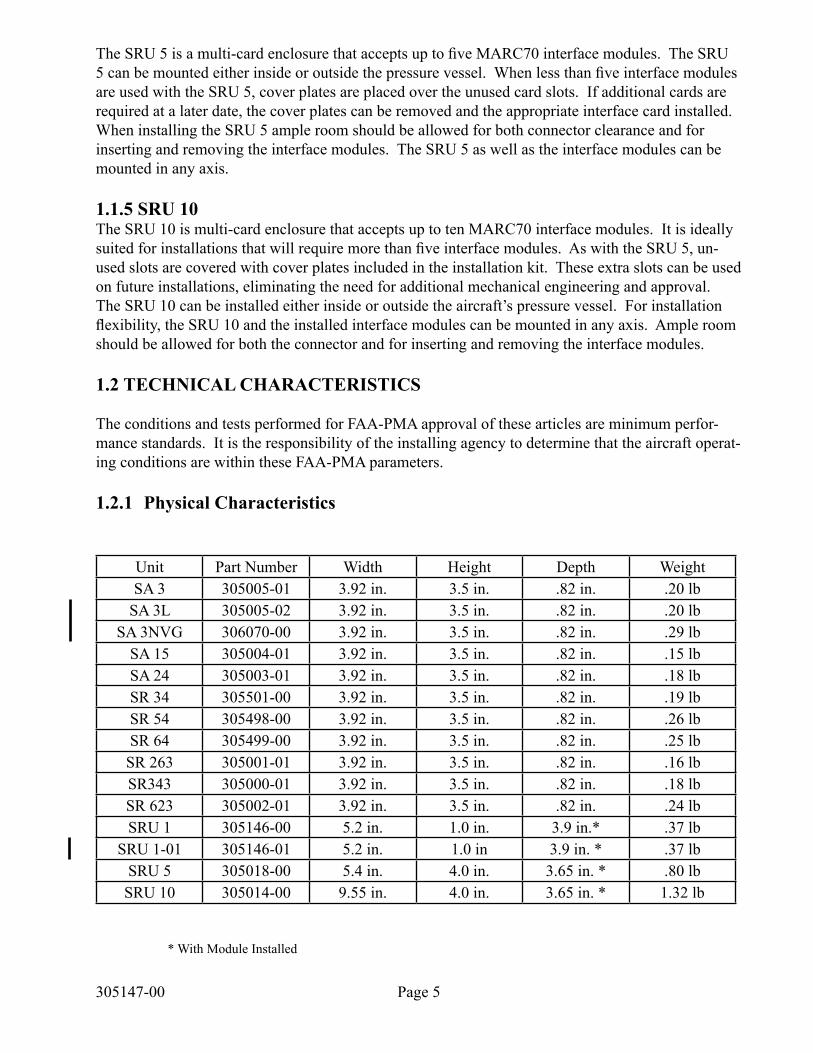
TheSRU5isamulti-cardenclosurethatacceptsuptofiveMARC70interfacemodules.TheSRU5canbemountedeitherinsideoroutsidethepressurevessel.Whenlessthanfiveinterfacemodulesare used with the SRU 5, cover plates are placed over the unused card slots. If additional cards are required at a later date, the cover plates can be removed and the appropriate interface card installed. When installing the SRU 5 ample room should be allowed for both connector clearance and for inserting and removing the interface modules. The SRU 5 as well as the interface modules can be mounted in any axis.
1.1.5 SRU 10The SRU 10 is multi-card enclosure that accepts up to ten MARC70 interface modules. It is ideally suitedforinstallationsthatwillrequiremorethanfiveinterfacemodules.AswiththeSRU5,un-used slots are covered with cover plates included in the installation kit. These extra slots can be used on future installations, eliminating the need for additional mechanical engineering and approval. The SRU 10 can be installed either inside or outside the aircraft’s pressure vessel. For installation flexibility,theSRU10andtheinstalledinterfacemodulescanbemountedinanyaxis.Ampleroomshould be allowed for both the connector and for inserting and removing the interface modules.
1.2 TECHNICAL CHARACTERISTICS
The conditions and tests performed for FAA-PMA approval of these articles are minimum perfor-mance standards. It is the responsibility of the installing agency to determine that the aircraft operat-ing conditions are within these FAA-PMA parameters.
1.2.1 Physical Characteristics
* With Module Installed
Page 5305147-00
Unit Part Number Width Height Depth WeightSA 3 305005-01 3.92 in. 3.5 in. .82 in. .20 lb
SA 3L 305005-02 3.92 in. 3.5 in. .82 in. .20 lbSA3NVG 306070-00 3.92 in. 3.5 in. .82 in. .29 lb
SA 15 305004-01 3.92 in. 3.5 in. .82 in. .15 lbSA 24 305003-01 3.92 in. 3.5 in. .82 in. .18 lbSR 34 305501-00 3.92 in. 3.5 in. .82 in. .19 lbSR 54 305498-00 3.92 in. 3.5 in. .82 in. .26 lbSR 64 305499-00 3.92 in. 3.5 in. .82 in. .25 lb
SR 263 305001-01 3.92 in. 3.5 in. .82 in. .16 lbSR343 305000-01 3.92 in. 3.5 in. .82 in. .18 lbSR 623 305002-01 3.92 in. 3.5 in. .82 in. .24 lbSRU 1 305146-00 5.2 in. 1.0 in. 3.9 in.* .37 lb
SRU 1-01 305146-01 5.2 in. 1.0 in 3.9 in. * .37 lbSRU 5 305018-00 5.4 in. 4.0 in. 3.65 in. * .80 lbSRU 10 305014-00 9.55 in. 4.0 in. 3.65 in. * 1.32 lb
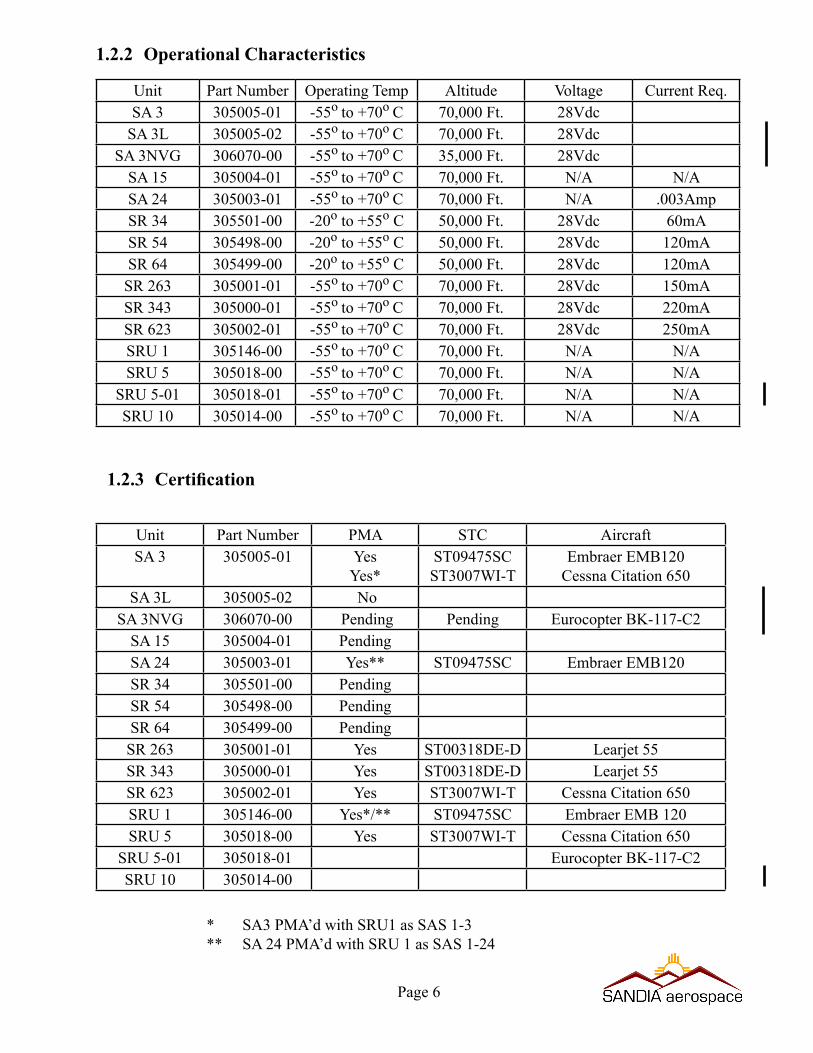
1.2.2 Operational Characteristics
1.2.3 Certification
Page 6
* SA3 PMA’d with SRU1 as SAS 1-3** SA 24 PMA’d with SRU 1 as SAS 1-24
Unit Part Number Operating Temp Altitude Voltage Current Req.SA 3 305005-01 -55o to +70o C 70,000 Ft. 28Vdc
SA 3L 305005-02 -55o to +70o C 70,000 Ft. 28VdcSA3NVG 306070-00 -55o to +70o C 35,000 Ft. 28Vdc
SA 15 305004-01 -55o to +70o C 70,000 Ft. N/A N/ASA 24 305003-01 -55o to +70o C 70,000 Ft. N/A .003AmpSR 34 305501-00 -20o to +55o C 50,000 Ft. 28Vdc 60mASR 54 305498-00 -20o to +55o C 50,000 Ft. 28Vdc 120mASR 64 305499-00 -20o to +55o C 50,000 Ft. 28Vdc 120mASR 263 305001-01 -55o to +70o C 70,000 Ft. 28Vdc 150mASR 343 305000-01 -55o to +70o C 70,000 Ft. 28Vdc 220mASR 623 305002-01 -55o to +70o C 70,000 Ft. 28Vdc 250mASRU 1 305146-00 -55o to +70o C 70,000 Ft. N/A N/ASRU 5 305018-00 -55o to +70o C 70,000 Ft. N/A N/A
SRU 5-01 305018-01 -55o to +70o C 70,000 Ft. N/A N/ASRU 10 305014-00 -55o to +70o C 70,000 Ft. N/A N/A
Unit Part Number PMA STC AircraftSA 3 305005-01 Yes
Yes*ST09475SCST3007WI-T
Embraer EMB120Cessna Citation 650
SA 3L 305005-02 No SA3NVG 306070-00 Pending Pending Eurocopter BK-117-C2
SA 15 305004-01 PendingSA 24 305003-01 Yes** ST09475SC Embraer EMB120SR 34 305501-00 PendingSR 54 305498-00 PendingSR 64 305499-00 PendingSR 263 305001-01 Yes ST00318DE-D Learjet 55SR 343 305000-01 Yes ST00318DE-D Learjet 55SR 623 305002-01 Yes ST3007WI-T Cessna Citation 650SRU 1 305146-00 Yes*/** ST09475SC Embraer EMB 120SRU 5 305018-00 Yes ST3007WI-T Cessna Citation 650
SRU 5-01 305018-01 Eurocopter BK-117-C2SRU 10 305014-00
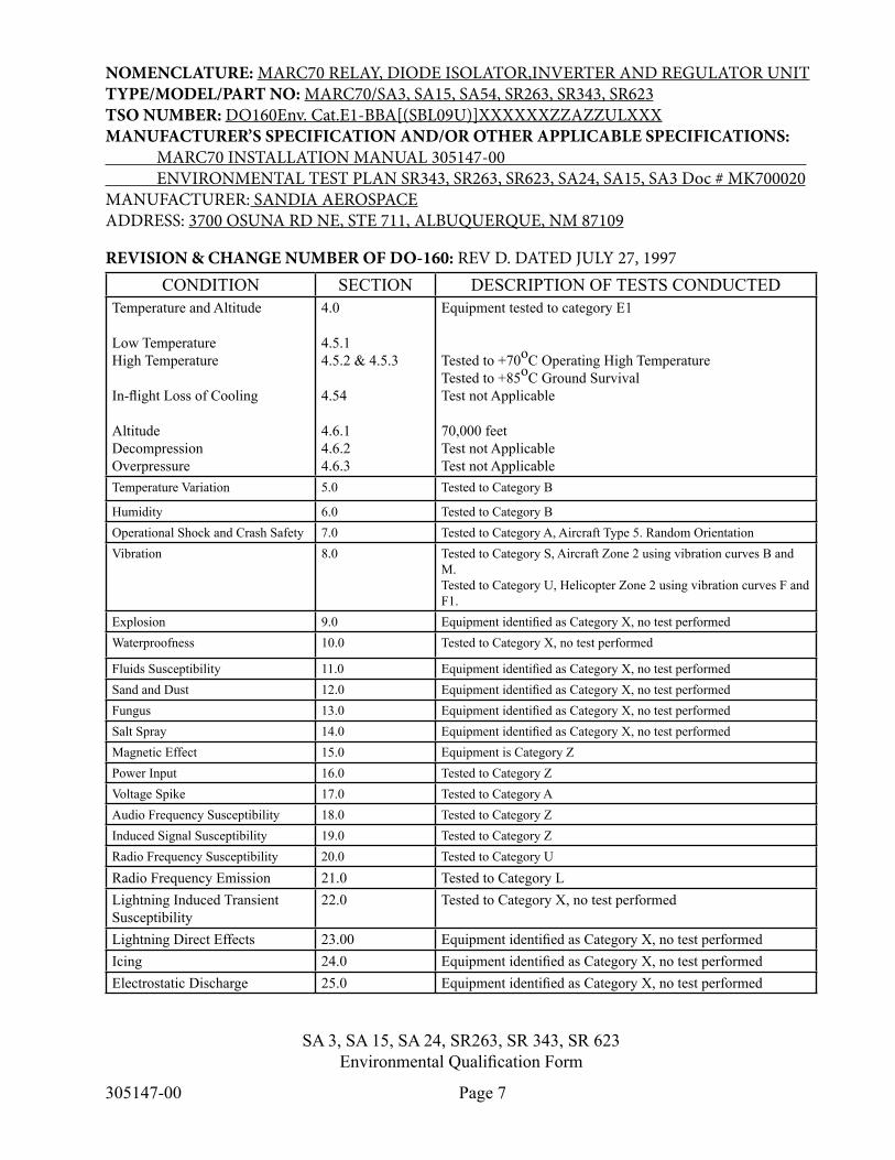
SA 3, SA 15, SA 24, SR263, SR 343, SR 623EnvironmentalQualificationForm
Page 7305147-00
NOMENCLATURE: MARC70 RELAY, DIODE ISOLATOR,INVERTER AND REGULATOR UNITTYPE/MODEL/PART NO: MARC70/SA3, SA15, SA54, SR263, SR343, SR623TSO NUMBER: DO160Env. Cat.E1-BBA[(SBL09U)]XXXXXXZZAZZULXXXMANUFACTURER’S SPECIFICATION AND/OR OTHER APPLICABLE SPECIFICATIONS: MARC70 INSTALLATION MANUAL 305147-00 ENVIRONMENTAL TEST PLAN SR343, SR263, SR623, SA24, SA15, SA3 Doc # MK700020MANUFACTURER: SANDIA AEROSPACEADDRESS: 3700 OSUNA RD NE, STE 711, ALBUQUERQUE, NM 87109
REVISION & CHANGE NUMBER OF DO-160: REV D. DATED JULY 27, 1997CONDITION SECTION DESCRIPTION OF TESTS CONDUCTED
Temperature and Altitude
Low TemperatureHigh Temperature
In-flightLossofCooling
AltitudeDecompressionOverpressure
4.0
4.5.14.5.2 & 4.5.3
4.54
4.6.14.6.24.6.3
Equipment tested to category E1
Tested to +70oC Operating High TemperatureTested to +85oC Ground SurvivalTest not Applicable
70,000 feetTest not ApplicableTest not Applicable
TemperatureVariation 5.0 Tested to Category B
Humidity 6.0 Tested to Category BOperational Shock and Crash Safety 7.0 Tested to Category A, Aircraft Type 5. Random OrientationVibration 8.0 Tested to Category S, Aircraft Zone 2 using vibration curves B and
M. Tested to Category U, Helicopter Zone 2 using vibration curves F and F1.
Explosion 9.0 EquipmentidentifiedasCategoryX,notestperformedWaterproofness 10.0 TestedtoCategoryX,notestperformed
Fluids Susceptibility 11.0 EquipmentidentifiedasCategoryX,notestperformedSand and Dust 12.0 EquipmentidentifiedasCategoryX,notestperformedFungus 13.0 EquipmentidentifiedasCategoryX,notestperformedSalt Spray 14.0 EquipmentidentifiedasCategoryX,notestperformedMagnetic Effect 15.0 Equipment is Category ZPower Input 16.0 Tested to Category ZVoltageSpike 17.0 Tested to Category AAudio Frequency Susceptibility 18.0 Tested to Category ZInduced Signal Susceptibility 19.0 Tested to Category ZRadio Frequency Susceptibility 20.0 Tested to Category U
Radio Frequency Emission 21.0 Tested to Category LLightning Induced Transient Susceptibility
22.0 TestedtoCategoryX,notestperformed
Lightning Direct Effects 23.00 EquipmentidentifiedasCategoryX,notestperformedIcing 24.0 EquipmentidentifiedasCategoryX,notestperformedElectrostatic Discharge 25.0 EquipmentidentifiedasCategoryX,notestperformed
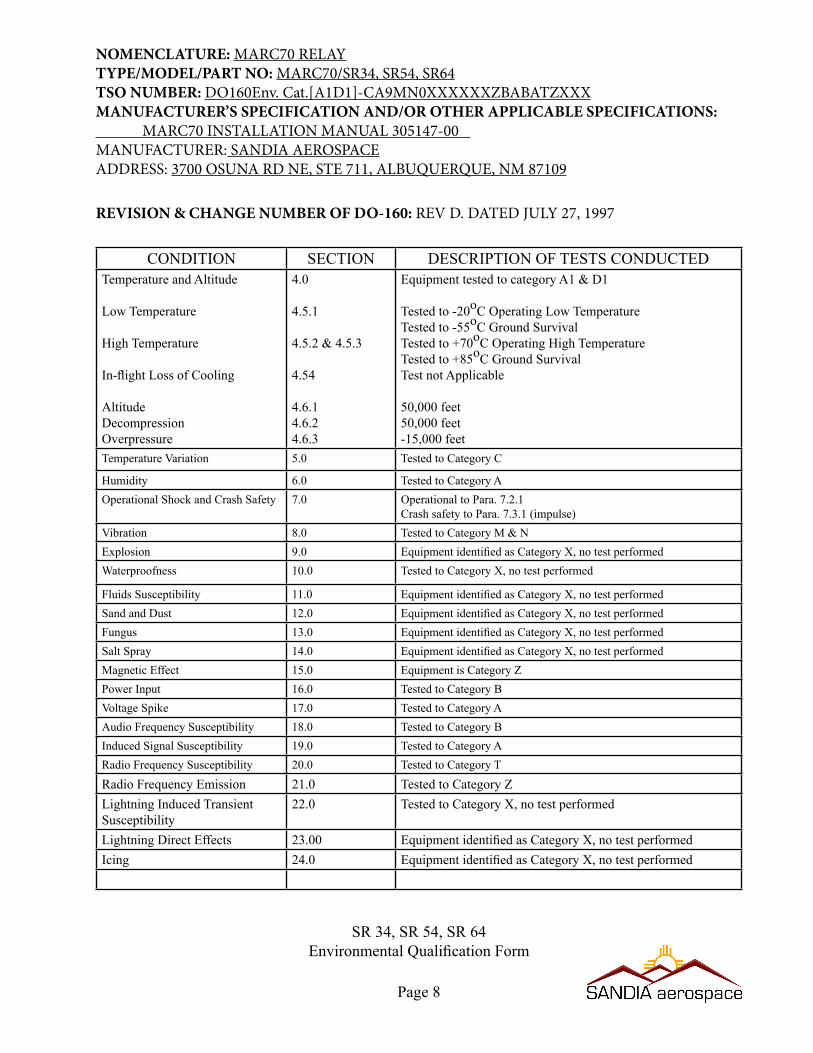
SR 34, SR 54, SR 64EnvironmentalQualificationForm
Page 8
NOMENCLATURE: MARC70 RELAYTYPE/MODEL/PART NO: MARC70/SR34, SR54, SR64TSO NUMBER: DO160Env. Cat.[A1D1]-CA9MN0XXXXXXZBABATZXXXMANUFACTURER’S SPECIFICATION AND/OR OTHER APPLICABLE SPECIFICATIONS: MARC70 INSTALLATION MANUAL 305147-00 MANUFACTURER: SANDIA AEROSPACEADDRESS: 3700 OSUNA RD NE, STE 711, ALBUQUERQUE, NM 87109
CONDITION SECTION DESCRIPTION OF TESTS CONDUCTEDTemperature and Altitude
Low Temperature
High Temperature
In-flightLossofCooling
AltitudeDecompressionOverpressure
4.0
4.5.1
4.5.2 & 4.5.3
4.54
4.6.14.6.24.6.3
Equipment tested to category A1 & D1 Tested to -20oC Operating Low TemperatureTested to -55oC Ground SurvivalTested to +70oC Operating High TemperatureTested to +85oC Ground SurvivalTest not Applicable
50,000 feet50,000 feet-15,000 feet
TemperatureVariation 5.0 Tested to Category C
Humidity 6.0 Tested to Category AOperational Shock and Crash Safety 7.0 Operational to Para. 7.2.1
CrashsafetytoPara.7.3.1(impulse)Vibration 8.0 Tested to Category M & NExplosion 9.0 EquipmentidentifiedasCategoryX,notestperformedWaterproofness 10.0 TestedtoCategoryX,notestperformed
Fluids Susceptibility 11.0 EquipmentidentifiedasCategoryX,notestperformedSand and Dust 12.0 EquipmentidentifiedasCategoryX,notestperformedFungus 13.0 EquipmentidentifiedasCategoryX,notestperformedSalt Spray 14.0 EquipmentidentifiedasCategoryX,notestperformedMagnetic Effect 15.0 Equipment is Category ZPower Input 16.0 Tested to Category BVoltageSpike 17.0 Tested to Category AAudio Frequency Susceptibility 18.0 Tested to Category BInduced Signal Susceptibility 19.0 Tested to Category ARadio Frequency Susceptibility 20.0 Tested to Category T
Radio Frequency Emission 21.0 Tested to Category ZLightning Induced Transient Susceptibility
22.0 TestedtoCategoryX,notestperformed
Lightning Direct Effects 23.00 EquipmentidentifiedasCategoryX,notestperformedIcing 24.0 EquipmentidentifiedasCategoryX,notestperformed
REVISION & CHANGE NUMBER OF DO-160: REV D. DATED JULY 27, 1997
Page 9
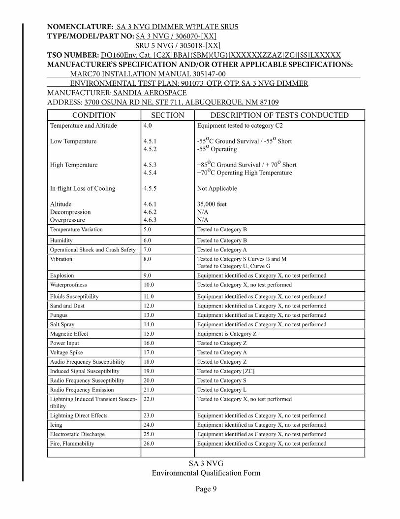
NOMENCLATURE: SA 3 NVG DIMMER W?PLATE SRU5TYPE/MODEL/PART NO: SA 3 NVG / 306070-[XX] SRU 5 NVG / 305018-[XX]TSO NUMBER: DO160Env. Cat. [C2X]BBA[(SBM)(UG)]XXXXXXZZAZ[ZC][SS]LXXXXXMANUFACTURER’S SPECIFICATION AND/OR OTHER APPLICABLE SPECIFICATIONS: MARC70 INSTALLATION MANUAL 305147-00 ENVIRONMENTAL TEST PLAN: 901073-QTP, QTP, SA 3 NVG DIMMERMANUFACTURER: SANDIA AEROSPACEADDRESS: 3700 OSUNA RD NE, STE 711, ALBUQUERQUE, NM 87109
CONDITION SECTION DESCRIPTION OF TESTS CONDUCTEDTemperature and Altitude
Low Temperature
High Temperature
In-flightLossofCooling
AltitudeDecompressionOverpressure
4.0
4.5.14.5.2
4.5.34.5.4
4.5.5
4.6.14.6.24.6.3
Equipment tested to category C2 -55oC Ground Survival / -55o Short-55o Operating
+85oC Ground Survival / + 70o Short+70oC Operating High Temperature
Not Applicable
35,000 feetN/AN/A
TemperatureVariation 5.0 Tested to Category B
Humidity 6.0 Tested to Category BOperational Shock and Crash Safety 7.0 Tested to Category AVibration 8.0 Tested to Category S Curves B and M
Tested to Category U, Curve GExplosion 9.0 EquipmentidentifiedasCategoryX,notestperformedWaterproofness 10.0 TestedtoCategoryX,notestperformed
Fluids Susceptibility 11.0 EquipmentidentifiedasCategoryX,notestperformedSand and Dust 12.0 EquipmentidentifiedasCategoryX,notestperformedFungus 13.0 EquipmentidentifiedasCategoryX,notestperformedSalt Spray 14.0 EquipmentidentifiedasCategoryX,notestperformedMagnetic Effect 15.0 Equipment is Category ZPower Input 16.0 Tested to Category ZVoltageSpike 17.0 Tested to Category AAudio Frequency Susceptibility 18.0 Tested to Category ZInduced Signal Susceptibility 19.0 Tested to Category [ZC]Radio Frequency Susceptibility 20.0 Tested to Category SRadio Frequency Emission 21.0 Tested to Category LLightning Induced Transient Suscep-tibility
22.0 TestedtoCategoryX,notestperformed
Lightning Direct Effects 23.0 EquipmentidentifiedasCategoryX,notestperformedIcing 24.0 EquipmentidentifiedasCategoryX,notestperformedElectrostatic Discharge 25.0 EquipmentidentifiedasCategoryX,notestperformedFire, Flammability 26.0 EquipmentidentifiedasCategoryX,notestperformed
SA3NVGEnvironmentalQualificationForm

2.2 Mounting Considerations
The MARC70 family of interface modules and their associated mounting enclosures can be mounted in any attitude and either inside or outside the pressure vessel. Each card is installed in the desired mounting enclosure by inserting it into a vacant location and secur-ing it with the two stainless steel fasteners attached to the modules front plate. The interface modules can only be inserted and secured in one direction. While the modules are relatively easy to install and remove in the enclosures, considerations should be given to service access. At least six inches of clearance should be provided at the front of the enclosures for removal and reinsertion of MARC70 modules It is also recommended that enough cable be supplied so that the interface modules can be inserted and removed with the cable harness and connec-tor attached to the module. This will aid in any calibration that may be required and will also simplify attaching the connector to the interface module.
.2.3 CoolingCooling for the MARC70 is not required. However if several higher current modules, such as annunciator drivers are installed, adequate space should be allowed for convection cool-ing.TheSA3NVGmustbemountedintherightmostslotoftheSRU-5-01,PN305018-01and secured with two screws supplied with the unit.
Section 3 Installation Procedures3.1 General
Each MARC70 module is supplied with a mating connector, crimp style pins and an indenti-ficationtag.Theidentificationtagistobeplacedonthetopoftheenclosuredirectlyovertheslot in which the module is installed. The enclosures are supplied with enough blank plates and screws to cover any unused slots. Extra blank plates and screws can be discarded or retained in case a module is ever removed.
3.2 Mounting Instructions
The SRU 1 is attached to an aircraft structure by using four #10-32 screws as shown in the outline drawing.
Section 2 Installation2.1 Introduction
The MARC70 family of enclosures and interface modules has been designed to simplify and standardize installation of avionics systems. SANDIA aerospace supplies each mounting enclosure and interface module separately. The installer can mix and match the modules in theenclosurestomeetspecificrequirements.ExceptfortheSR34,SR54andSR64,eachof the module’s connectors is keyed to prevent inadvertently attaching the wrong connector. It is important that the installer insert the supplied plug in the proper location in the mating connector for the keying to be complete.
305147-00 Page 10
Page 11
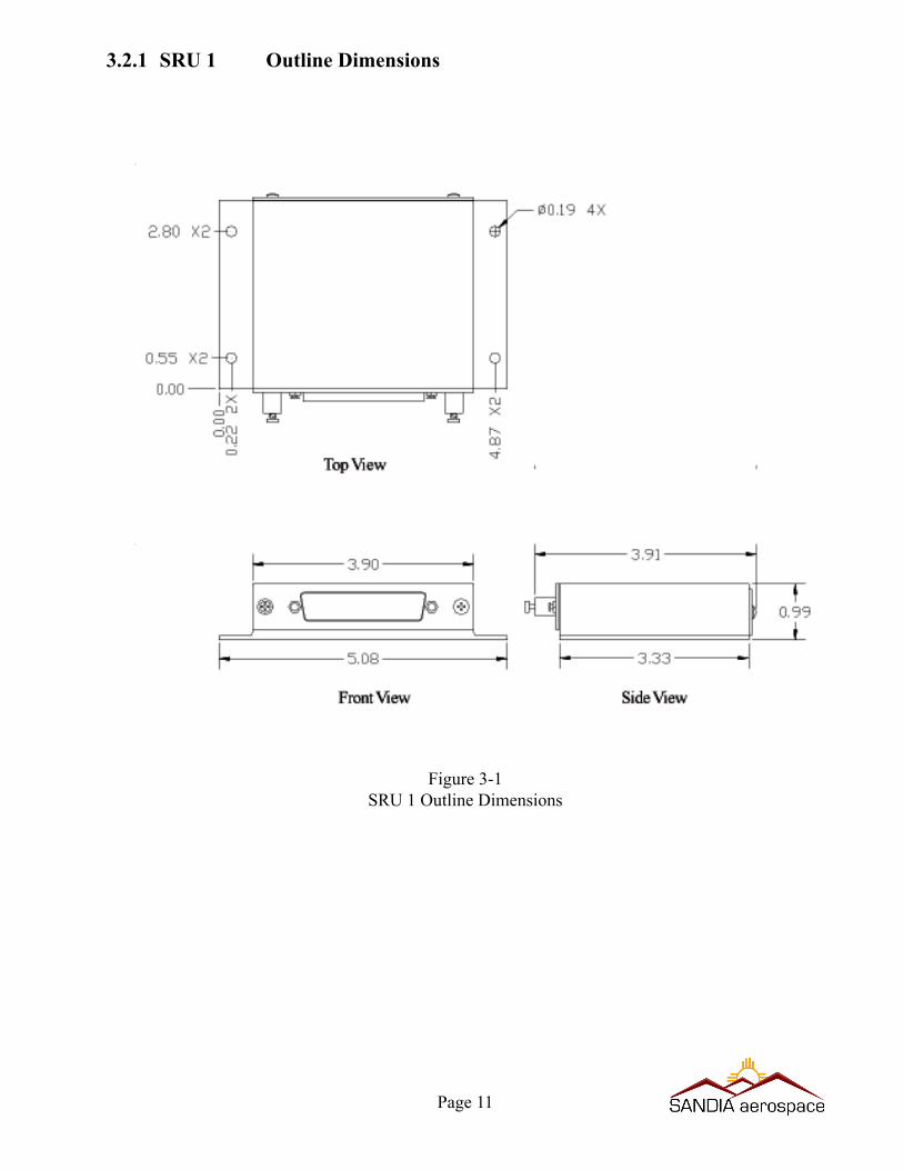
3.2.1 SRU 1 Outline Dimensions
Figure 3-1SRU 1 Outline Dimensions
305147-00
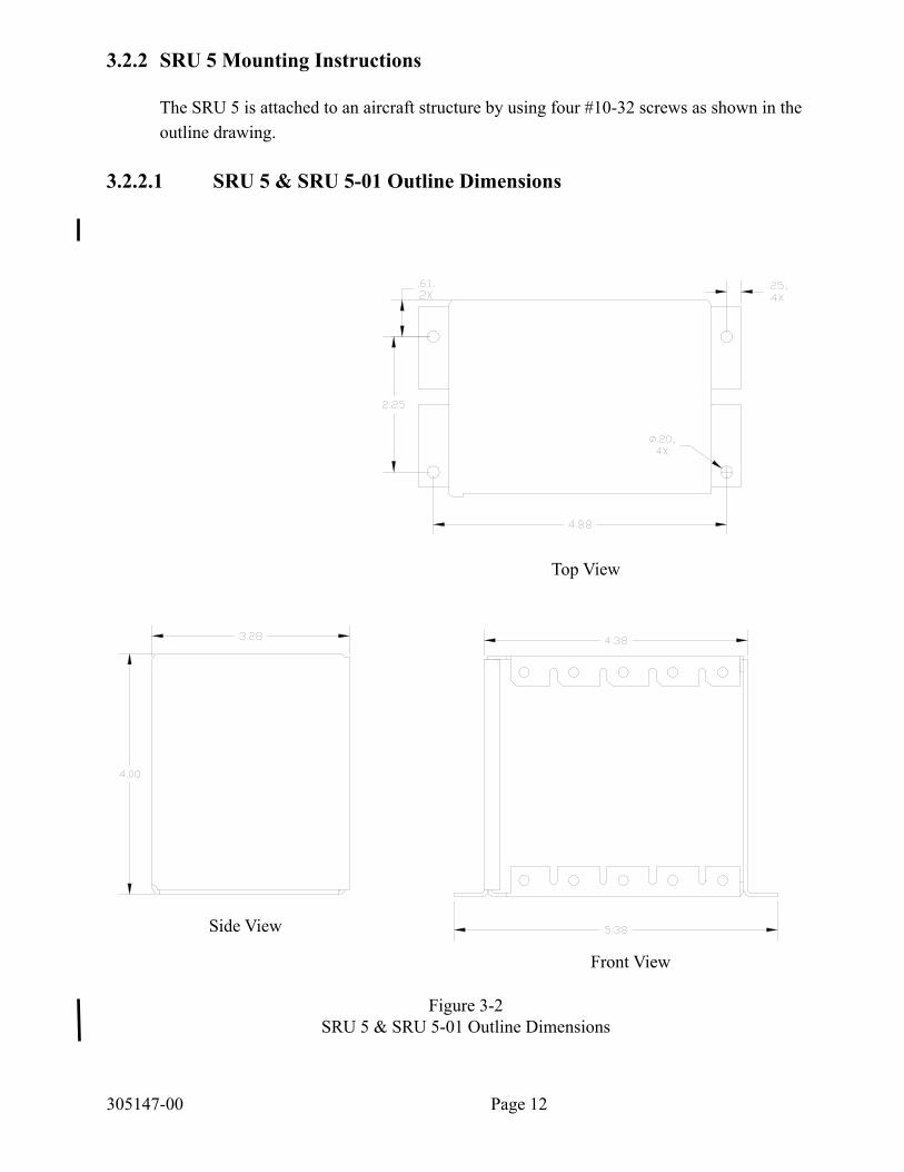
3.2.2 SRU 5 Mounting Instructions
The SRU 5 is attached to an aircraft structure by using four #10-32 screws as shown in the outline drawing.
3.2.2.1 SRU 5 & SRU 5-01 Outline Dimensions
TopView
FrontView
SideView
Figure 3-2SRU 5 & SRU 5-01 Outline Dimensions
Page 12

3.2.3 SRU 10 Mounting Instructions
The SRU 10 is attached to an aircraft structure by using four #10-32 screws as shown in the outline drawing.
3.2.3.1 SRU 10 Outline Dimensions
Page 13
TopView
FrontViewSideView
Figure 3-3SRU 10 Outline Dimensions
3.3 Interconnect Wiring
The SA 3 & 3L Regulator/ Dimming Modules provide a source of power to drive up to .5 amps of continuous current for aircraft annunciators. The SA 3 & 3L will provide 1 amp short term for testing of annunciators. Aircraft power is supplied to 7 pins for installation flexibility.TwoadjustmentsallowsettingtheHighandLowintensityoftheannunciatorstomatch existing aircraft annunciators.
Pin 2 on the SA 3 & 3L is the keying pin and has been removed at the factory. A plug which is supplied with the installation kit must be inserted into Pin 2 of the mating connector.
The SA 3 is for use with incandesent lamps while the SA 3L is for use with LED Lamps.
Seefigure3-4foraschematicandpinoutoftheSA3&3L
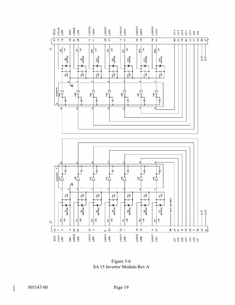
3.3.3 SA 15 Inverter ModuleTheSA15moduleallowsequipmentwith+5Vdcor+28Vdclampoutputstodrivepanelannunciator lamps that require grounded inputs. The SA 15 inverts up to 14 high level lamp-driver inputs providing independent low outputs for each line. The 14 inverters are arranged intwobanksof7invertersforinstallationflexibility.Asinglelineoneachinverterbankallows simultaneous testing of all 7 outputs. The inverters may also be cascaded, providing consistent drive polarity and simplifying press to test wiring of panel annunciators.
Pin 36 on the SA 15 is the keying pin and has been removed at the factory. A plug which is supplied with the installation kit must be inserted into Pin 36 of the mating connector.
Seefigure3-5foraschematicandpinoutoftheSA15
Page 14305147-00
3.3.2 SA 3 NVG Regulator/ Dimming ModuleTheSA3NVGRegulator/DimmingModuleprovideasourceofpowertodriveupto.5ampsofcontinuouscurrentforaircraftannunciators.TheSA3NVGwillprovide1ampshorttermfortestingofannunciators.Aircraftpowerissuppliedto7pinsforinstallationflexibility.ThreeadjustmentsallowsettingtheHigh,LowandNVGintensityoftheannunciators.AgroundisappliedtoPin4oftheconnnectorJ1toputtheSA3NVGintheNVGmode.AgroundonJ1Pin3putstheoutputinDim(night)modeandwithbothJ1Pins3and4opentheoutputisintheBright(day)mode.
TheSA3NVGmustbemountedintherightmostslotoftotheSRU5-01SandiaP/N305018-01 and secured with two 1/2 inch 4-40 screws supplied with the unit. The SRU 5 actsasaheatsinkandshouldnotbemountednearflamablesubstances.
Pin2ontheSA3NVGisthekeyingpinandhasbeenremovedatthefactory.Aplugwhichissupplied with the installation kit must be inserted into Pin 2 of the mating connector.
3.3.1 SA 3 & SA 3L Regulator/ Dimming Modules

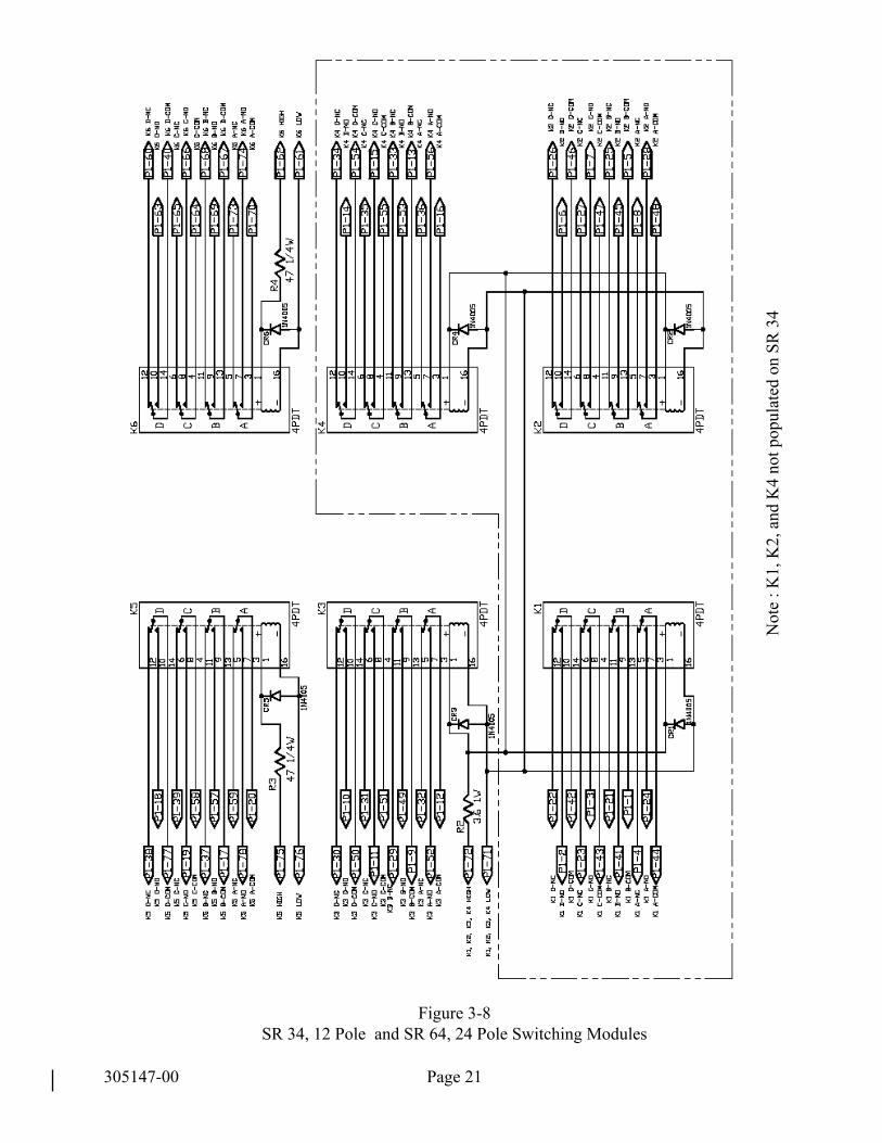
3.3.5 SR 34 12 Pole Switching ModuleThe SR 34 provides 12 poles of switching through three, hermetically sealed, bifurcated re-lays.Therelayscontactsaregoldplatedandhavea2ampresistiveloadratingat28VDC.Coil current is 60 mA. Both the SR 34 and SR 64 use the same circuit card. Each relay is independently switched through their appropriate coil pins.
Seefigure3-7foraschematicandpinoutoftheSR34
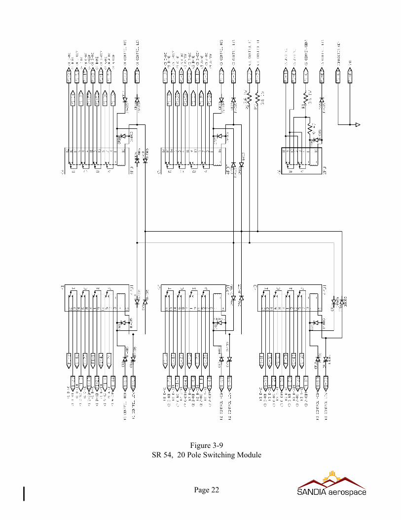
3.3.6 SR 54 20 Pole Switching Module
3.3.7 SR 64 24 Pole Switching Module
Page 15
TheSR54provides20polesofswitchingthroughfive,hermeticallysealed,bifurcatedre-lays. The SR 54 has a built in circuit that swithces all relays to their de-energized conditon whenever K6 is activated. This can be used for such applications as insuring LOC is present-ed on the HSI whenever a LOC signal is selected. The relays contacts are gold plated and havea2ampresistiveloadratingat28VDC.Coilcurrentis120mA.
Seefigure3-8foraschematicandpinoutoftheSR54
The SR 64 provides 24 poles of switching through six, hermetically sealed, bifurcated relays. Therelayscontactsaregoldplatedandhavea2ampresistiveloadratingat28VDC.Coilcurrent is 120 mA. K1, K2, K3 and K4 are switched simultaneoulsy through coil pins, 71 and 72. K5 and K6 are independently switched through their coil pins.
Seefigure3-7foraschematicandpinoutoftheSR64
CAUTIONSince all pins on the SR 34, SR 54 and SR 64 are used for switching func-tions, there is NO KEYING PIN. Cautions must be taken when reattaching the connector to insure that it is going to the correct devise. Failure to do so may result in board damage.
3.3.4 SA 24 Diode Isolation/Test ModuleThe SA 24 provides 23 lines of diode isolation. The SA 24 also provides a test input for testing annunciators. The test input can be either a high or a low. Pin 48 on the SA 24 is the keying pin and has been removed at the factory. A plug which is supplied with the installa-tion kit must be inserted into Pin 48 of the mating connector.

305147-00
3.3.9 SR 343 12 Pole Switching ModuleTheSR343provides12polesofrelayswitchingthrough3MILQualified,hermeticallysealed,andnitrogenfilledrelays.Therelayscontactsaregoldplatedhardenedsilveralloywitha2ampresistiveloadcapacityat28Vdc.Eachofthethreerelayscanbeactivatedin-dependently by supplying switching logic to their coils through pins 38 & 40 for K1, pins 43 & 44 for K2 and pins 48 & 49 for K3. They can also be switched as group by suppling the switching logic to pins 39 & 45.
Pin 42 on the SR 343 is the keying pin and has been removed at the factory. A plug which is supplied with the installation kit must be inserted into Pin 42 of the mating connector.
Seefigure3-10foraschematicandpinoutoftheSR343
3.3.10 SR 623 12 Pole Switching ModuleTheSR623provides12polesofswitchingthrough6MILQualified,hermeticallysealed,andnitrogenfilledrelays.Therelayscontactsaregoldplatedhardenedsilveralloywitha2ampresistiveloadcapacityat28Vdc.Eachofthe6relaysareswitchedindependentlyorcan be switched in any combination by supplying common switching logic to their respective coils.
Pin 39 on the SR 623 is the keying pin and has been removed at the factory. A plug which is supplied with the installation kit must be inserted into Pin 39 of the mating connector.
Page 16
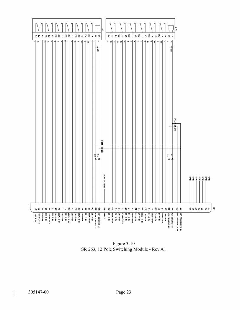
TheSR263provides12polesofswitchingthroughtwoMILQualified,hermeticallysealed,andnitrogenfilledrelays.Therelayscontactsaregoldplatedhardenedsilveralloywitha2ampresistiveloadcapacityat28Vdc.Coilpoweris2.6wattsmax.at25degreesC.
Each relay can be activated independently by supplying the switching logic to their coil through pins 38 & 40 for K1 and 43 & 44 for K2. Or they can be switched as a pair by sup-plying the switching logic to pins 39 & 45.
Pin 46 on the SR 263 is the keying pin and has been removed at the factory. A plug which is supplied with the installation kit must be inserted into Pin 46 of the mating connector.
Seefigure3-9foraschematicandpinoutoftheSR263
3.3.8 SR 263 12 Pole Switching Module
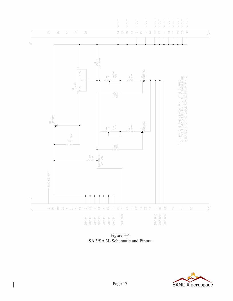
Figure 3-4SA 3/SA 3L Schematic and Pinout
Page 17
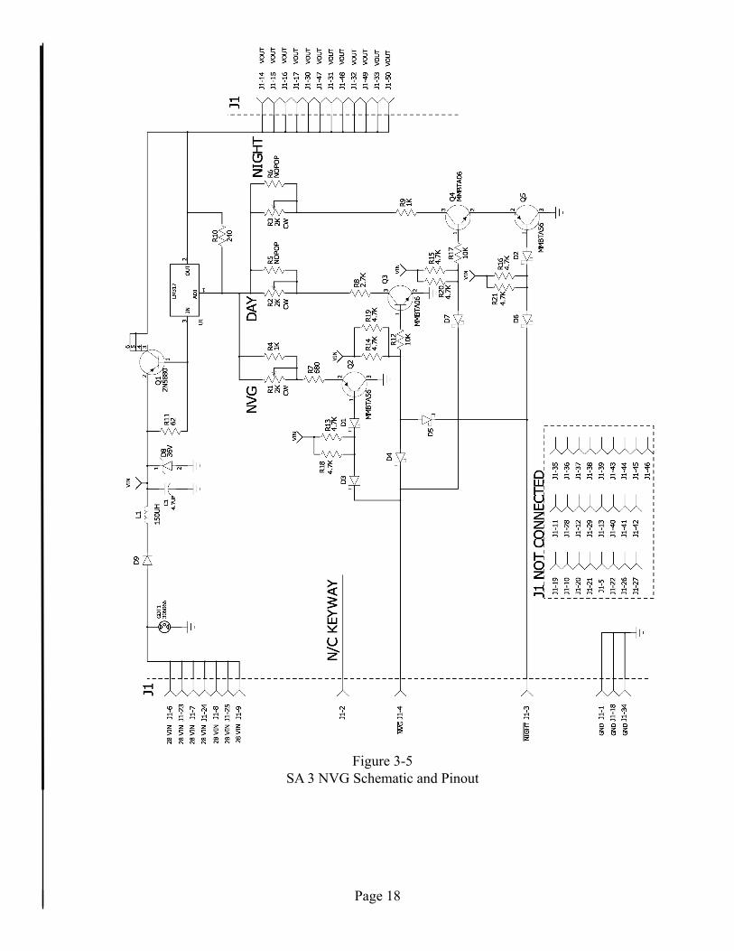
Figure 3-5SA3NVGSchematicandPinout
Page 18
305147-00
Figure 3-6SA 15 Invertor Module-Rev A
Page 19

Figure 3-7SA 24 Diode Isolation/Test Module
Page 20
Page 21
Figure 3-8SR 34, 12 Pole and SR 64, 24 Pole Switching Modules
Not
e : K
1, K
2, a
nd K
4 no
t pop
ulat
ed o
n SR
34
305147-00
Page 22
Figure 3-9SR 54, 20 Pole Switching Module
305147-00
Figure 3-10SR 263, 12 Pole Switching Module - Rev A1
Page 23
(JPEGImage,2672x3129pixels)-Scaled(37%)https://mail.google.com/mail/?ui=2&ik=f3aa80e6ac&view=att&th=132e...
1 of 110/11/2011 8:28 AM
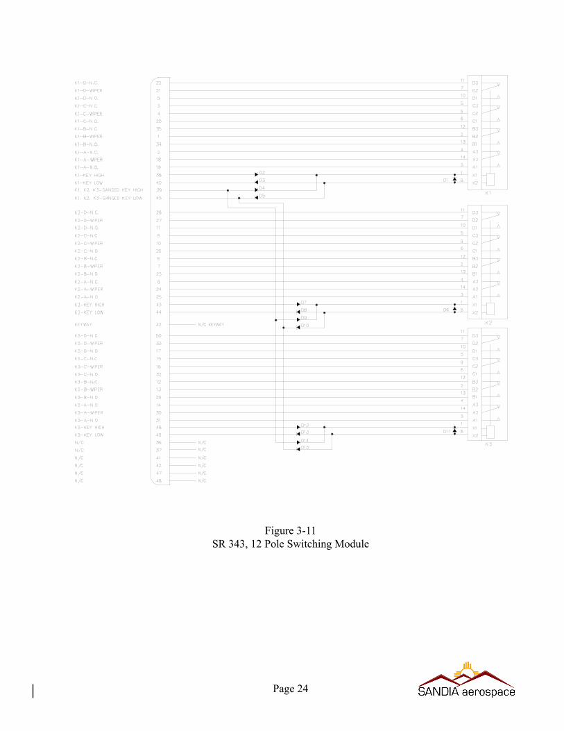
Figure 3-11SR 343, 12 Pole Switching Module
Page 24

305147-00
Figure 3-12SR 623, 12 Switching Module
Page 25
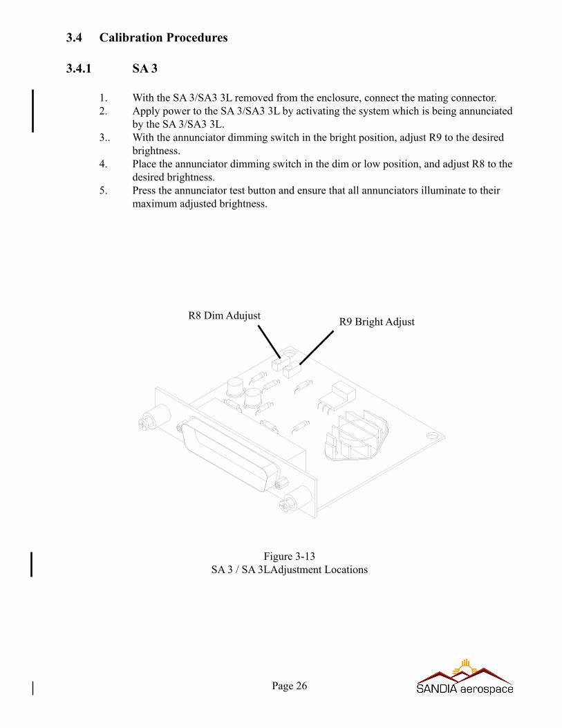
3.4 Calibration Procedures
3.4.1 SA 3
1. With the SA 3/SA3 3L removed from the enclosure, connect the mating connector.2. Apply power to the SA 3/SA3 3L by activating the system which is being annunciated
by the SA 3/SA3 3L.3.. With the annunciator dimming switch in the bright position, adjust R9 to the desired
brightness.4. Place the annunciator dimming switch in the dim or low position, and adjust R8 to the
desired brightness.5. Press the annunciator test button and ensure that all annunciators illuminate to their
maximum adjusted brightness.
R8 Dim Adujust R9 Bright Adjust
Figure 3-13SA 3 / SA 3LAdjustment Locations
Page 26

3.4 Calibration Procedures con’t
3.4.2 SA 3NVG
1. WiththeSA3NVGremovedfromtheenclosure,connectthematingconnector.2. ApplypowertotheSA3NVGbyactivatingthesystemwhichisbeingannunciated
bytheSA3NVG.3.. WiththeannunciatordimmingswitchintheDay(Bright)brightposition,setthe
DAY adjustment to the desired brightness.4. PlacetheannunciatordimmingswitchintheNight(dim),andsettheNIGHTtothe
desired brightness.5. PlacetheannunciatordinningswitchintheNVGandsettheNVGadjustmenttothe
desiredNVGsetting.6. Press the annunciator test button and ensure that all annunciators illuminate to their
maximum adjusted brightness.
NVG
DAY
NIGHT
Figure 3-14SA3NVGAdjustmentLocations
Page 27
Page 28
3.5 Continued Airworthiness
Maintenance of all MARC70 products contained in this manual is on condition only. No scheduled maintenance is required.